EP3700302A1 - Induction heating roller and spun yarn drawing device - Google Patents
Induction heating roller and spun yarn drawing device Download PDFInfo
- Publication number
- EP3700302A1 EP3700302A1 EP18869072.1A EP18869072A EP3700302A1 EP 3700302 A1 EP3700302 A1 EP 3700302A1 EP 18869072 A EP18869072 A EP 18869072A EP 3700302 A1 EP3700302 A1 EP 3700302A1
- Authority
- EP
- European Patent Office
- Prior art keywords
- fixing ring
- induction heating
- axial direction
- roller
- magnetic member
- Prior art date
- Legal status (The legal status is an assumption and is not a legal conclusion. Google has not performed a legal analysis and makes no representation as to the accuracy of the status listed.)
- Granted
Links
Images






Classifications
-
- H—ELECTRICITY
- H05—ELECTRIC TECHNIQUES NOT OTHERWISE PROVIDED FOR
- H05B—ELECTRIC HEATING; ELECTRIC LIGHT SOURCES NOT OTHERWISE PROVIDED FOR; CIRCUIT ARRANGEMENTS FOR ELECTRIC LIGHT SOURCES, IN GENERAL
- H05B6/00—Heating by electric, magnetic or electromagnetic fields
- H05B6/02—Induction heating
- H05B6/10—Induction heating apparatus, other than furnaces, for specific applications
- H05B6/14—Tools, e.g. nozzles, rollers, calenders
- H05B6/145—Heated rollers
-
- D—TEXTILES; PAPER
- D01—NATURAL OR MAN-MADE THREADS OR FIBRES; SPINNING
- D01D—MECHANICAL METHODS OR APPARATUS IN THE MANUFACTURE OF ARTIFICIAL FILAMENTS, THREADS, FIBRES, BRISTLES OR RIBBONS
- D01D10/00—Physical treatment of artificial filaments or the like during manufacture, i.e. during a continuous production process before the filaments have been collected
- D01D10/02—Heat treatment
-
- D—TEXTILES; PAPER
- D01—NATURAL OR MAN-MADE THREADS OR FIBRES; SPINNING
- D01D—MECHANICAL METHODS OR APPARATUS IN THE MANUFACTURE OF ARTIFICIAL FILAMENTS, THREADS, FIBRES, BRISTLES OR RIBBONS
- D01D5/00—Formation of filaments, threads, or the like
- D01D5/12—Stretch-spinning methods
- D01D5/16—Stretch-spinning methods using rollers, or like mechanical devices, e.g. snubbing pins
-
- D—TEXTILES; PAPER
- D02—YARNS; MECHANICAL FINISHING OF YARNS OR ROPES; WARPING OR BEAMING
- D02J—FINISHING OR DRESSING OF FILAMENTS, YARNS, THREADS, CORDS, ROPES OR THE LIKE
- D02J1/00—Modifying the structure or properties resulting from a particular structure; Modifying, retaining, or restoring the physical form or cross-sectional shape, e.g. by use of dies or squeeze rollers
- D02J1/22—Stretching or tensioning, shrinking or relaxing, e.g. by use of overfeed and underfeed apparatus, or preventing stretch
- D02J1/224—Selection or control of the temperature during stretching
-
- D—TEXTILES; PAPER
- D02—YARNS; MECHANICAL FINISHING OF YARNS OR ROPES; WARPING OR BEAMING
- D02J—FINISHING OR DRESSING OF FILAMENTS, YARNS, THREADS, CORDS, ROPES OR THE LIKE
- D02J13/00—Heating or cooling the yarn, thread, cord, rope, or the like, not specific to any one of the processes provided for in this subclass
- D02J13/005—Heating or cooling the yarn, thread, cord, rope, or the like, not specific to any one of the processes provided for in this subclass by contact with at least one rotating roll
-
- F—MECHANICAL ENGINEERING; LIGHTING; HEATING; WEAPONS; BLASTING
- F16—ENGINEERING ELEMENTS AND UNITS; GENERAL MEASURES FOR PRODUCING AND MAINTAINING EFFECTIVE FUNCTIONING OF MACHINES OR INSTALLATIONS; THERMAL INSULATION IN GENERAL
- F16C—SHAFTS; FLEXIBLE SHAFTS; ELEMENTS OR CRANKSHAFT MECHANISMS; ROTARY BODIES OTHER THAN GEARING ELEMENTS; BEARINGS
- F16C13/00—Rolls, drums, discs, or the like; Bearings or mountings therefor
- F16C13/006—Guiding rollers, wheels or the like, formed by or on the outer element of a single bearing or bearing unit, e.g. two adjacent bearings, whose ratio of length to diameter is generally less than one
-
- F—MECHANICAL ENGINEERING; LIGHTING; HEATING; WEAPONS; BLASTING
- F16—ENGINEERING ELEMENTS AND UNITS; GENERAL MEASURES FOR PRODUCING AND MAINTAINING EFFECTIVE FUNCTIONING OF MACHINES OR INSTALLATIONS; THERMAL INSULATION IN GENERAL
- F16C—SHAFTS; FLEXIBLE SHAFTS; ELEMENTS OR CRANKSHAFT MECHANISMS; ROTARY BODIES OTHER THAN GEARING ELEMENTS; BEARINGS
- F16C2202/00—Solid materials defined by their properties
- F16C2202/20—Thermal properties
-
- F—MECHANICAL ENGINEERING; LIGHTING; HEATING; WEAPONS; BLASTING
- F16—ENGINEERING ELEMENTS AND UNITS; GENERAL MEASURES FOR PRODUCING AND MAINTAINING EFFECTIVE FUNCTIONING OF MACHINES OR INSTALLATIONS; THERMAL INSULATION IN GENERAL
- F16C—SHAFTS; FLEXIBLE SHAFTS; ELEMENTS OR CRANKSHAFT MECHANISMS; ROTARY BODIES OTHER THAN GEARING ELEMENTS; BEARINGS
- F16C2240/00—Specified values or numerical ranges of parameters; Relations between them
- F16C2240/06—Temperature
-
- F—MECHANICAL ENGINEERING; LIGHTING; HEATING; WEAPONS; BLASTING
- F16—ENGINEERING ELEMENTS AND UNITS; GENERAL MEASURES FOR PRODUCING AND MAINTAINING EFFECTIVE FUNCTIONING OF MACHINES OR INSTALLATIONS; THERMAL INSULATION IN GENERAL
- F16C—SHAFTS; FLEXIBLE SHAFTS; ELEMENTS OR CRANKSHAFT MECHANISMS; ROTARY BODIES OTHER THAN GEARING ELEMENTS; BEARINGS
- F16C2340/00—Apparatus for treating textiles
- F16C2340/18—Apparatus for spinning or twisting
-
- F—MECHANICAL ENGINEERING; LIGHTING; HEATING; WEAPONS; BLASTING
- F16—ENGINEERING ELEMENTS AND UNITS; GENERAL MEASURES FOR PRODUCING AND MAINTAINING EFFECTIVE FUNCTIONING OF MACHINES OR INSTALLATIONS; THERMAL INSULATION IN GENERAL
- F16C—SHAFTS; FLEXIBLE SHAFTS; ELEMENTS OR CRANKSHAFT MECHANISMS; ROTARY BODIES OTHER THAN GEARING ELEMENTS; BEARINGS
- F16C2380/00—Electrical apparatus
-
- F—MECHANICAL ENGINEERING; LIGHTING; HEATING; WEAPONS; BLASTING
- F16—ENGINEERING ELEMENTS AND UNITS; GENERAL MEASURES FOR PRODUCING AND MAINTAINING EFFECTIVE FUNCTIONING OF MACHINES OR INSTALLATIONS; THERMAL INSULATION IN GENERAL
- F16C—SHAFTS; FLEXIBLE SHAFTS; ELEMENTS OR CRANKSHAFT MECHANISMS; ROTARY BODIES OTHER THAN GEARING ELEMENTS; BEARINGS
- F16C41/00—Other accessories, e.g. devices integrated in the bearing not relating to the bearing function as such
Definitions
- the present invention relates to an induction heating roller and a spun yarn drawing device including one or more induction heating rollers.
- Patent Literature 1 discloses an induction heating roller configured to heat yarns.
- the induction heating roller includes: a hollow roller main body; and a coil provided radially inward of the roller main body. As an alternating current flows through the coil, eddy currents are induced in the roller main body due to electromagnetic induction, and the roller main body is heated by Joule heating (that is, heat is generated in the roller main body by induction heating).
- the induction heating roller is supported in a cantilever manner so that yarns can be easily wound onto the roller.
- Induction heating rollers each generally has difficulty in obtaining equal distribution of the surface temperature of the roller main body in its axial direction because heat generation therein is less likely to be equal in the axial direction and because heat is more likely to be dissipated at axial end portions of the roller main body to the outside.
- an induction heating roller described in Patent Literature 2 includes a jacket chamber filled with a heating medium in a gas-liquid two-phase state, and the jacket chamber is provided in a roller main body so as to extend in an axial direction of the roller.
- the jacket chamber functions as a heat pipe, the inequality in the distribution of the surface temperature of the roller main body in the axial direction is improved.
- the present inventors conceived an idea of providing a cylindrical heat equalizing member having a heat conductivity higher than that of the roller main body, in contact with an inner circumferential surface of the roller main body. This facilitates equalization in the distribution of the surface temperature of the roller main body because the heat equalizing member functions as a heat pipe. Furthermore, it is possible to efficiently heat the roller main body because the thickness of the roller main body is smaller and therefore the increase in the heat capacity is smaller.
- the heat equalizing member is applied to an induction heating roller supported in a cantilever manner, as described in Patent Literature 1.
- the heat equalizing member is inserted into a space radially inside the roller main body through an opening of the roller main body, which is provided at its base-end-side portion in the axial direction ("axial base end portion").
- a ring-like fixing member (hereinafter referred to as a "fixing ring”) for fixing the roller main body and the heat equalizing member to each other is attached to the axial base end portion of the roller main body, for example.
- the fixing ring is arranged to extend further radially inward relative to the heat equalizing member in order to firmly fix the heat equalizing member provided radially inward of the roller main body.
- the present inventors used carbon steel, which is a ferromagnetic material, as a material of the fixing ring, based on the following grounds: the present inventors used such a fixing ring in order to improve the distribution of the surface temperature of the roller main body by facilitating the flow of magnetic flux through the fixing ring to facilitate the generation of eddy currents, thereby to increase the amount of heat generation at the base end portion of the roller main body.
- An object of the present invention is to mitigate heat generation in a fixing ring provided to an induction heating roller.
- an induction heating roller includes: a rotatable roller unit; and a heater including a coil provided radially inward of the roller unit.
- the roller unit includes: a roller main body including a cylindrical heating target configured to be heated by induction heating due to magnetic flux passing in an axial direction of the roller unit, the magnetic flux being generated by electric current flowing through the coil; a heat equalizing unit including a heat equalizing member which is in contact with an inner circumferential surface of the heating target, the heat equalizing member extending in the axial direction, and having a heat conductivity higher at least than that of the inner circumferential surface of the heating target; a fixing ring provided so as to be in contact with a first-side end portion of the heating target which is on a first side in the axial direction and with a first-side end portion of the heat equalizing unit which is on the first side in the axial direction, the fixing ring fixing the roller main body and the heat equalizing unit to each other; and a first magnetic member provided between the heating
- the fixing ring is provided so as to be in contact with the first-side end portion of the heating target and with the first-side end portion of the heat equalizing unit in the axial direction of the roller unit (hereinafter, simply referred to as an "axial direction"), and the fixing ring fixes the roller main body and the heat equalizing unit to each other.
- At least a part of the fixing ring is, in general, positioned closer to the coil than the heating target and the heat equalizing unit in the radial direction.
- Magnetic flux tends to, in nature, concentratedly flow into the shortest path, through which magnetic flux readily passes, among paths for magnetic flux, and therefore in the above configuration, magnetic flux is more likely to flow into the fixing ring. This increases the possibility that heat is generated in the fixing ring due to induction heating.
- the first magnetic member is provided radially inward of the heating target, and is provided on the first side relative to the axial center of the heating target in the axial direction and on the second side relative to the fixing ring in the axial direction.
- appropriately disposing the first magnetic member makes it possible to form a new path through which magnetic flux more readily passes than a path extending via the fixing ring. Due to this, as compared to the case in which no first magnetic member is provided, the amount of magnetic flux passing through the fixing ring can be reduced, leading to reduction of eddy currents generated in the fixing ring. Accordingly, it is possible to mitigate heat generation in the fixing ring provided to the induction heating roller.
- the induction heating roller of the first aspect is arranged such that the heat equalizing member has a relative permeability lower than that of the fixing ring.
- the induction heating roller of the first or second aspect is arranged such that the first magnetic member is provided so as to correspond to a whole circumference of the fixing ring in a circumferential direction of the fixing ring.
- the inflow of magnetic flux into the fixing ring is further reduced as compared to the case in which the first magnetic member is provided only partially with respect to the circumferential direction of the fixing ring.
- the induction heating roller of any of the first to third aspects is arranged such that the first magnetic member is in contact with the inner circumferential surface of the heating target.
- the above arrangement facilitates the flow of magnetic flux between the first magnetic member and the heating target, and therefore it is possible to reduce the amount of magnetic flux detouring to flow into the fixing ring.
- the induction heating roller of any of the first to fourth aspects is arranged such that the first magnetic member is in contact with the heat equalizing member.
- the first magnetic member As magnetic flux passes through the first magnetic member, the first magnetic member is also heated by induction heating. Because the first magnetic member is in contact with the heat equalizing member in this aspect, heat generated in the first magnetic member is transmitted to the heating target via the heat equalizing member. This makes it possible to efficiently heat the heating target.
- the induction heating roller of any of the first to fifth aspects is arranged such that there is a gap between the first magnetic member and the fixing ring in the axial direction.
- the induction heating roller of any of the first to sixth aspects is arranged such that the heat equalizing unit includes: a pressing member provided side by side on the first side of the heat equalizing member in the axial direction and configured to press the heat equalizing member; and a biasing member provided between the pressing member and the fixing ring in the axial direction and configured to bias the pressing member toward the second side in the axial direction, and such that the pressing member is provided to function as the first magnetic member.
- the pressing member is biased in the axial direction, and by the biased pressing member, the heat equalizing member is pressed in the axial direction. This makes it possible to firmly fix the heat equalizing member in the axial direction. Furthermore, because the pressing member is provided to function as the first magnetic member, an increase in cost is smaller as compared to the case in which the first magnetic member and the pressing member are provided as different members.
- the induction heating roller of any of the first to seventh aspects is arranged such that the heater includes a second magnetic member provided radially outward of the coil, the second magnetic member being provided so as to be opposed to the first magnetic member in the radial direction.
- the heater is provided with the second magnetic member. This makes it possible to form a path through which magnetic flux readily passes along the second magnetic member. This facilitates the flow of magnetic flux between the first and second magnetic members opposed to each other in the radial direction when the magnetic flux flows between the heater provided radially inside and the roller unit provided radially outside. Accordingly, it is possible to reliably reduce the amount of magnetic flux passing through the fixing ring.
- the induction heating roller of the eighth aspect is arranged such that the second magnetic member is structured by a plurality of parts arranged in the circumferential direction of the fixing ring.
- the flow of the magnetic flux between the first magnetic member and the second magnetic member is further facilitated, as compared to the case in which the second magnetic member is provided to cover only a limited area with respect to the circumferential direction of the fixing ring.
- the induction heating roller of the eighth or ninth aspect is arranged such that: the heater includes a third magnetic member provided adjacent to an end portion of the coil on the first side in the axial direction, the third magnetic member extending further radially outward relative to the coil; and the second magnetic member is provided in contact with the third magnetic member.
- magnetic flux generated by currents flowing through the coil is intentionally guided by the third magnetic member to the second magnetic member.
- the magnetic flux are reliably introduced into the second magnetic member.
- the induction heating roller of any of the first to tenth aspects is arranged such that the fixing ring has a relative permeability lower than that of the first magnetic member.
- the fixing ring has the lower relative permeability, and this makes it less likely that magnetic flux passes through the fixing ring, and therefore eddy currents are less likely to flow in the fixing ring. This makes the heat generation in the fixing ring further smaller.
- an induction heating roller includes: a rotatable roller unit; and a heater including a coil provided radially inward of the roller unit.
- the roller unit includes: a roller main body including a cylindrical heating target configured to be heated by induction heating due to magnetic flux passing in an axial direction of the roller, the magnetic flux being generated by electric current flowing through the coil; a heat equalizing unit including a heat equalizing member which is in contact with an inner circumferential surface of the heating target, the heat equalizing member extending in the axial direction and having a heat conductivity higher at least than that of the inner circumferential surface of the heating target; and a fixing ring provided so as to be in contact with a first-side end portion of the heating target which is on a first side in the axial direction and with a first-side end portion of the heat equalizing unit which is on the first side in the axial direction, the fixing ring fixing the roller main body and the heat equalizing unit to each other.
- the fixing ring includes a
- the fixing ring is arranged to extend further radially inward relative to the heating target and the heat equalizing unit, which increases the likelihood of inflow of magnetic flux into the fixing ring.
- This may cause a problem that the magnetic flux passing through the fixing ring induces eddy currents whirling in the circumferential direction of the fixing ring, to cause great heat generation in the fixing ring.
- the high resistive portion is provided at a part of the fixing ring in the circumferential direction, and the high resistive portion decreases the eddy currents flowing in the circumferential direction of the fixing ring. Accordingly, it is possible to mitigate heat generation in the fixing ring provided to the induction heating roller.
- the induction heating roller of the twelfth aspect is arranged such that the high resistive portion has a cross-sectional area, which is orthogonal to the circumferential direction, smaller than that of a portion of the fixing ring other than the high resistive portion.
- the electric resistance in the circumferential direction is higher at the high resistive portion.
- the high electric resistance in the circumferential direction of the fixing ring makes it possible to reduce the eddy currents.
- the induction heating roller of the thirteenth aspect is arranged such that: the high resistive portion has a hole; and the high resistive portion has a cross-sectional area smaller than that of the portion of the fixing ring other than the high resistive portion, due to a presence of the hole.
- the high resistive portion with a smaller cross-sectional area is easily provided just by boring a hole at a part of the fixing ring.
- the induction heating roller of the fourteenth aspect is arranged such that the hole is filled with an insulator.
- Providing a hollow hole at a part of the fixing ring in the circumferential direction may decrease the strength of the fixing ring at the high resistive portion.
- the insulator filling the hole mitigates such a decrease in strength of the fixing ring.
- the induction heating roller of the twelfth aspect is arranged such that: the fixing ring includes a plurality of ring pieces which are separable in the circumferential direction; the ring pieces are connected to each other via insulators; and portions of the fixing ring in which the insulators are respectively provided in the circumferential direction function as the high resistive portion.
- the induction heating roller of any of the first to sixteenth aspects is arranged such that: the roller main body is supported in a cantilever manner; and the fixing ring is provided, in the axial direction, at a base end portion of the heating target, which is the first-side end portion of the heating target.
- a spun yarn drawing device includes the induction heating roller recited in any one of the first to seventeenth aspects, and the apparatus is arranged such that a plurality of yarns are wound onto an outer circumferential surface of the induction heating roller in a lined-up manner in the axial direction.
- FIG. 1 is a front view of the spun yarn take-up machine 1.
- the description below is given on the premise that the up-down direction, front-back direction, and left-right direction shown in FIG. 1 are respectively the up-down direction, front-back direction, and left-right direction relative to the spun yarn take-up machine 1.
- the spun yarn take-up machine 1 is configured so that yarns Y spun out from a spinning apparatus 2 are drawn in a spun yarn drawing device 3 and the drawn yarns Y are wound up in a yarn winding apparatus 4.
- the spinning apparatus 2 is configured to produce yarns Y by continuously spinning out molten polymer such as nylon and polyester. To the yarns Y spun out from the spinning apparatus 2, oil is applied at an oil guide 10. The yarns Y are then sent to the spun yarn drawing device 3 via a guide roller 11.
- the spun yarn drawing device 3 is an apparatus for drawing the yarns Y and is provided below the spinning apparatus 2.
- the spun yarn drawing device 3 includes godet rollers 21 to 25 housed in a thermal insulation box 12.
- the godet rollers 21 to 25 are configured to be driven and rotated by respective motors.
- Each of the godet rollers 21 to 25 is the induction heating roller 20 heated by induction heating using a coil.
- Yarns Y are wound onto an outer circumferential surface of each of the godet rollers 21 to 25.
- the thermal insulation box 12 has, at a lower portion of its right side surface, an inlet 12a through which yarns Y are introduced into the thermal insulation box 12.
- the thermal insulation box 12 further has, at an upper portion of its right side surface, an outlet 12b through which yarns Y go out of the thermal insulation box 12. Yarns Y are wound onto each of the godet rollers 21 to 25, in order from the lowermost godet roller 21, at a winding angle smaller than 360 degrees.
- the lower three godet rollers 21 to 23 are preheating rollers configured to preliminarily heat yarns Y before drawing them.
- the roller surface temperature of each of these rollers is arranged to be equal to or higher than the glass transition temperature of the yarns Y (e.g., on the order of 90 to 100 degrees centigrade).
- the upper two godet rollers 24 and 25 are conditioning rollers configured to thermally set the drawn yarns Y.
- the surface temperature of each of these rollers is arranged to be higher than the surface temperatures of the lower three godet rollers 21 to 23 (e.g., on the order of 150 to 200 degrees centigrade).
- the yarn feeding speeds of the upper two godet rollers 24 and 25 are higher than those of the lower three godet rollers 21 to 23.
- the yarns Y introduced into the thermal insulation box 12 through the inlet 12a are, at first, preliminarily heated to a drawable temperature while being transferred by the godet rollers 21 to 23.
- the preliminarily heated yarns Y are drawn due to the difference in yarn feeding speed between the godet roller 23 and the godet roller 24.
- the yarns Y are then further heated to a higher temperature while being transferred by the godet rollers 24 and 25, with the result that the drawn yarns Y are thermally set.
- the yarns Y having been drawn in this way go out from the thermal insulation box 12 through the outlet 12b.
- the yarns Y drawn by the spun yarn drawing device 3 are sent to the yarn winding apparatus 4 via a guide roller 13.
- the yarn winding apparatus 4 is an apparatus for winding the yarns Y and is provided below the spun yarn drawing device 3.
- the yarn winding apparatus 4 includes a bobbin holder 14, a contact roller 15, and the like.
- the bobbin holder 14 has a cylindrical shape extending in the front-back direction, and is driven and rotated by a motor, which is not illustrated.
- Bobbins B arranged side by side in an axial direction of the bobbin holder 14 are attached to the bobbin holder 14.
- the yarn winding apparatus 4 is configured to wind yarns Y onto the bobbins B at the same time by rotating the bobbin holder 14, to produce packages P.
- the contact roller 15 is configured to come into contact with the surfaces of the packages P to adjust the shape of each package P by applying a predetermined contact pressure to each package P.
- FIG. 2 is a cross section of each induction heating roller 20.
- FIG. 3(a) is a perspective view of a heat equalizing unit 32 and the like, which will be described later.
- FIG. 3(b) is a diagram showing a heat equalizing member 41 pressed by a pressing member 42.
- a roller main body 31 of the induction heating roller 20 is supported in a cantilever manner by a motor 100 configured to rotate and drive the roller main body 31.
- a direction in which the roller main body 31 extends i.e., a left-right direction on the sheet of FIG.
- the axial direction of the roller main body 31 is identical with an axial direction of a roller unit 30 (which will be described later) and to an axial direction of a heat equalizing unit 32 (which will be described later).
- a side closer to the motor 100 in the axial direction is referred to as a "base end side” (a first side in the present invention).
- a side opposite from the base end side is referred to as a “leading end side” (a second side in the present invention).
- a radial direction of the roller main body 31 may be simply referred to as a "radial direction” or “radially”.
- a circumferential direction of the roller main body 31 may be simply referred to as a "circumferential direction”.
- the induction heating roller 20 includes: the rotatable roller unit 30; and a heater 50 provided radially inward of the roller unit 30.
- the induction heating roller 20 is configured to raise the temperature of an outer circumferential surface of the roller unit 30 by induction heating caused by a coil 52 provided in the heater 50, and thereby to heat yarns Y wound onto the roller unit 30.
- the roller unit 30 is rotated and driven by the motor 100.
- the heater 50 is fixed to a heater supporting portion (not illustrated) attached to the motor 100. That is, the roller unit 30 is configured to be rotatable but the heater 50 is configured to be non-rotatable.
- the roller unit 30 includes: the roller main body 31; the heat equalizing unit 32; and a fixing ring 33.
- the roller main body 31 is a cylindrical member and is configured to be rotated and driven by the motor 100.
- the heat equalizing unit 32 is provided radially inward of the roller main body 31 and radially outward of the coil 52.
- the heat equalizing unit 32 is provided to equalize the temperature distribution on the roller main body 31 in the axial direction.
- the fixing ring 33 is attached to an axial base end portion (a base end portion in the axial direction) of the roller main body 31.
- the fixing ring 33 fixes the roller main body 31 and the heat equalizing unit 32 to each other.
- the roller main body 31 is, for example, made of carbon steel, which is magnetic and conductive material.
- the roller main body 31 includes: an outer cylindrical portion 34 (a heating target in the present invention) with a cylindrical shape, which is provided radially outward of the coil 52 and extends in the axial direction; a cylindrical core portion 35 provided radially inward of the coil 52; and an end face portion 36 connecting a leading end portion of the outer cylindrical portion 34 to a leading end portion of the core portion 35.
- the roller main body 31 has an open end on the base end side.
- the outer cylindrical portion 34, the core portion 35, and the end face portion 36 are, for example, unitarily formed as a single member.
- the outer cylindrical portion 34, the core portion 35, and the end face portion 36 may be respectively formed by components different from each other.
- the outer cylindrical portion 34 is formed by a first component
- the core portion 35 and the end face portion 36 are formed by a second component.
- the first component and the second component are fixed to each other, for example, by welding, or fixed by a fixing member such as screws or the like.
- the whole of the roller main body 31 does not have to be made of one material (for example, of carbon steel mentioned above). That is, as long as the outer cylindrical portion 34 and the end face portion 36 are made of magnetic and conductive material, the rest of the roller main body 31 may be made of another material.
- the core portion 35 does not have to be made of magnetic material. Yarns Y are wound onto an outer circumferential surface 34a of the outer cylindrical portion 34. The length of the outer circumferential surface 34a in the axial direction is, for example, 180 mm.
- the heat equalizing unit 32 is in contact with an inner circumferential surface 34b of the outer cylindrical portion 34.
- the core portion 35 has a shaft inserting hole 35a in which a drive shaft 101 of the motor 100 is inserted.
- the drive shaft 101 is fitted in the shaft inserting hole 35a, and thereby the roller main body 31 is fixed to the drive shaft 101. This allows the roller main body 31 to be supported in a cantilever manner by the motor 100 and to be rotatable with the drive shaft 101.
- the end face portion 36 has, at its radially outer end portion, a contact surface 36a with which a leading end portion of the heat equalizing member 41 is in contact.
- the contact surface 36a is a tapered surface, which is sloped so that its thickness in the axial direction decreases toward radially outside.
- the heat equalizing unit 32 includes: the heat equalizing member 41, the pressing member 42, and springs 43 (a biasing member in the present invention).
- the heat equalizing member 41 is used to equalize the distribution of the surface temperature of the outer cylindrical portion 34 of the roller main body 31 in the axial direction.
- the heat equalizing member 41 is a cylindrical member provided radially inward of the outer cylindrical portion 34 of the roller main body 31 and radially outward of the coil 52.
- the heat equalizing member 41 is pressed by the pressing member 42 and by the springs 43 toward the leading end side in the axial direction and radially outward, and due to this, the heat equalizing member 41 is fixed to the roller main body 31 (the details thereof will be described later.)
- the heat equalizing member 41 is a cylindrical member extending in the axial direction, and is, for example, made of C/C composite material (carbon fiber reinforced-carbon matrix-composite material), which is a composite material of carbon fiber reinforcement in a matrix of graphite.
- the heat equalizing member 41 has a heat conductivity higher than that of the roller main body 31 made of carbon steel (at least higher than that of the inner circumferential surface 34b of the outer cylindrical portion 34). Due to its higher heat conductivity, the heat equalizing member 41 has a function of equalizing the temperature distribution on the outer cylindrical portion 34 in the axial direction.
- the heat conductivity of carbon steel is 51.5 W/mk
- the heat conductivity of C/C composite material in the axial direction is 404 W/mk.
- the heat equalizing member 41 has a relative permeability lower than that of the roller main body 31.
- the relative permeability of carbon steel is 100 to 2000, while the relative permeability of C/C composite material is approximately 1.
- the heat equalizing member 41 is in contact with the inner circumferential surface 34b of the outer cylindrical portion 34 of the roller main body 31. Now an area of the outer circumferential surface 34a of the outer cylindrical portion 34 with respect to the axial direction, onto which yarns Y are wound, is defined as a wound region R.
- the heat equalizing member 41 is provided to cover the wound region R with respect to the axial direction.
- the heat equalizing member 41 is structured by a plurality of heat equalizing pieces 44 separable with respect to the circumferential direction (see FIG. 3(a) ). A base-end-side end face 44a and a leading-end-side end surface 44b of each heat equalizing piece 44 are tapered.
- the end face 44a is arranged so that its radially outer edge is on the base end side relative to its radially inner edge, in the axial direction.
- the end surface 44b is arranged so that its radially outer edge is on the leading end side relative to its radially inner edge, in the axial direction.
- the end surface 44b is shaped to match with the contact surface 36a of the end face portion 36 of the roller main body 31.
- the pressing member 42 is biased by the springs 43, and thereby to press the heat equalizing member 41 toward the leading end side in the axial direction and outward in the radial direction.
- the pressing member 42 is a ring-like member (see FIG. 3(a) ), and its outer diameter and inner diameter are substantially equal to those of the heat equalizing member 41, respectively.
- a leading-end-side end face 42a of the pressing member 42 is a tapered pressing surface arranged so that its radially inner edge is on the leading end side in the axial direction relative to its radially outer edge. That is, the end face 42a is designed to match with the surface formed by the above-described base-end-side end faces 44a of the heat equalizing pieces 44.
- Each spring 43 is in a gap 45 between the pressing member 42 and the fixing ring 33 in the axial direction. Abase end portion and a leading end portion of the spring 43 are in contact with the fixing ring 33 and the pressing member 42, respectively, and the spring 43 is compressed in the axial direction. Due to this, each spring 43 biases, with its restoring force, the pressing member 42 toward the leading end side in the axial direction. Because the pressing member 42 is biased by the springs 43, the heat equalizing member 41 is pressed toward the leading end side in the axial direction (see an arrow in the left-right direction on the sheet of FIG. 3(b) ).
- the heat equalizing member 41 is pressed also outward in the radial direction (see arrows in the up-down direction on the sheet of FIG. 3(b) ).
- outer circumferential surfaces 44c of the heat equalizing pieces 44 are reliably brought into contact with the inner circumferential surface 34b of the outer cylindrical portion 34 of the roller main body 31.
- the number of springs 43 is not particularly limited. Instead of the one or more springs 43, a rubber elastic member or the like may be used as a biasing member biasing the pressing member 42.
- the fixing ring 33 is a ring-like member provided at an axial base end portion of the outer cylindrical portion 34 of the roller main body 31.
- the fixing ring 33 is, for example, made of carbon steel as same as the roller main body 31. That is, the relative permeability of the above-described heat equalizing member 41 is lower than the relative permeability of the fixing ring 33.
- the fixing ring 33 extends further radially outward relative to the outer cylindrical portion 34 of the roller main body 31, and extends further radially inward relative to the heat equalizing unit 32.
- a radially inner end portion of the fixing ring 33 is closer to the coil 52 than the outer cylindrical portion 34 and than the heat equalizing unit 32 in the radial direction.
- the fixing ring 33 is provided in contact with the axial base end portion of the roller main body 31 and with an axial base end portion of the heat equalizing unit 32.
- the fixing ring 33 has a surrounding portion 33a.
- the surrounding portion 33a is shaped so as to surround a part of the roller main body 31 and a part of the heat equalizing unit 32 with respect to three sides thereof, i.e., the radially outer side, the radially inner side, and the base end side in the axial direction.
- the fixing ring 33 has a recessed portion 33b to accommodate the springs 43.
- the recessed portion 33b provides the gap 45 between the pressing member 42 and the fixing ring 33 in the axial direction.
- the heater 50 includes: a bobbin member 51, the coil 52, and a flange 53.
- the coil 52 is wound around the bobbin member 51 extending in the axial direction.
- An axial base end portion of the bobbin member 51 is attached to the flange 53.
- the bobbin member 51 is a cylindrical member provided radially inward of the outer cylindrical portion 34 of the roller main body 31 and radially outward of the core portion 35.
- the bobbin member 51 is, for example, made of carbon steel as same as the roller main body 31.
- the coil 52 is wound around an outer periphery of the bobbin member 51.
- the coil 52 is used to heat the roller main body 31 by induction heating.
- the coil 52 which is wound around the bobbin member 51, is provided inward of the outer cylindrical portion 34 of the roller main body 31 and outward of the core portion 35.
- an alternating voltage is applied to the coil 52, an alternating current flows through the coil 52, to generate an alternating magnetic field.
- the flange 53 is a disc-like member.
- the flange 53 has, at its radially central portion, a through hole 53a so that the flange 53 and the drive shaft 101 of the motor 100 do not interfere with each other.
- the flange 53 is, for example, made of carbon steel as same as the roller main body 31.
- the flange 53 is provided at an axial base end portion of the heater 40.
- the axial base end portion of the bobbin member 51 is attached to the flange 53.
- the flange 53 is fixed to the heater supporting portion (not shown) of the motor 100.
- the flange 53 extends further radially outward relative to the coil 52.
- a radially outer end portion of the flange 53 is positioned on the base end side in the axial direction relative to the fixing ring 33 of the roller unit 30, so as to cover the fixing ring 33. There is a gap between the flange 53 and the fixing ring 33, to prevent interference between the flange 53 of the heater 50 configured not to rotate and the fixing ring 33 of the roller unit 30 configured to rotate.
- each induction heating roller 20 As an alternating voltage is applied to the coil 52 in each induction heating roller 20, an alternating current flows through the coil 52, to generate an alternating magnetic field, and magnetic flux passes through the outer cylindrical portion 34 of the roller main body 31 in the axial direction. This induces eddy currents flowing in the roller main body 31 in the circumferential direction, and the outer cylindrical portion 34 is heated by Joule heating.
- the induction heating rollers 20 each generally has difficulty in obtaining equal distribution of the surface temperature of the roller main body 31 because heat generation therein is less likely to be equal in the axial direction and because the heat is more likely to be dissipated at the axial end portions of the roller main body 31 to the outside.
- the heat equalizing member 41 is used to equalize the distribution of temperature on the outer cylindrical portion 34 in the axial direction. As described above, the heat equalizing member 41 has a lower relative permeability. Therefore, the magnetic flux is less likely to pass through the heat equalizing member 41, and heat is less likely to be generated in the heat equalizing member 41.
- the present inventors used carbon steel, which is a ferromagnetic material, as a material of the fixing ring 33 in order to improve the distribution of the surface temperature of the roller main body by facilitating the flow of magnetic flux through the fixing ring 33 to facilitate the generation of eddy currents, thereby to increase the amount of heat generation at the base end portion of the roller main body 31.
- Magnetic flux tends to, in nature, concentratedly flow through the shortest path, through which magnetic flux readily passes, among paths for magnetic flux.
- the present inventors selected at first SUS (Steel Use Stainless), which is a non-magnetic material, as a material of the pressing member 42 so that magnetic flux passes through the fixing ring 33 rather than through the pressing member 42.
- SUS Step Use Stainless
- the heater 50 turned on, excessive heat was generated in the fixing ring 33 and the temperature at the base end portion of the roller main body 31 rose higher than that of its axially central portion, disadvantageously.
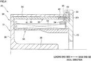
- a path 201 through which magnetic flux readily passes is formed by the members made of ferromagnetic carbon steel.
- arrows are depicted just to improve visibility.
- the direction of the magnetic flux changes when the direction of the current flowing through the coil 52 changes.
- the path 201 extends through the bobbin member 51, the flange 53, the fixing ring 33, the outer cylindrical portion 34 of the roller main body 31, and the end face portion 36. Because magnetic flux tends to, in nature, pass near a surface of a ferromagnetic material ("skin effect"), the path 201 is formed so as to pass on or near the surfaces of the above-described members.
- the fixing ring 33 is provided at the base end portion of the roller unit 30 supported in a cantilever manner, and a portion of the fixing ring 33 which faces the outside is smaller than that of a leading end portion of the roller unit 30. Therefore, the heat is less likely to be dissipated from the fixing ring 33.
- the heat generated in the fixing ring 33 is more likely to be transmitted toward a leading-end-side portion of the outer cylindrical portion 34 of the roller main body 31 before it is dissipated to the outside.
- the present inventors considered that this tends to cause a temperature gradient, in which the higher temperatures are observed at a base-end-side portion of the outer cylindrical portion 34 while lower temperatures are observed at the leading-end-side portion thereof, resulting in the problem of poor distribution of temperature on the outer circumferential surface 34a of the outer cylindrical portion 34.
- each induction heating roller 20 has the below-described configuration. Specifically, a description will be given, referring back to FIG. 2 and FIG. 3 .
- each induction heating roller 20 has the following configuration so as to provide another path through which magnetic flux readily passes, which is different from the above-described path 201 (see FIG. 4 ).
- the pressing member 42 provided to press the heat equalizing member 41 is made of carbon steel, which is a ferromagnetic material, as same as the roller main body 31 and the like.
- the pressing member 42 is referred to as a first magnetic member 46.
- the pressing member 42 is used as the first magnetic member 46. As shown in FIG.
- the first magnetic member 46 is provided between the outer cylindrical portion 34 of the roller main body 31 and the coil 52 in the radial direction, and is provided on the base end side relative to the center of the outer cylindrical portion 34 in the axial direction and on the leading end side relative to the fixing ring 33.
- the first magnetic member 46 is in contact with the inner circumferential surface 34b of the outer cylindrical portion 34 and in contact with the heat equalizing member 41.
- the first magnetic member 46 is provided so as to correspond to the whole circumference in the circumferential direction, as shown in FIG. 3(a) , for example.
- the present invention is not limited to this.
- the first magnetic member 46 may be structured by parts separable in the circumferential direction and arranged with spaces interposed between them.
- the heater 50 includes a second magnetic member 54.
- the second magnetic member 54 is made of carbon steel, as same as the first magnetic member 46. As shown in FIG. 2 , the second magnetic member 54 is provided radially outward of the coil 52, and is provided so as to be opposed to the first magnetic member 46 in the radial direction.
- the second magnetic member 54 is attached to the flange 53 (a third magnetic member of the present invention), and is in contact with the flange 53.
- the second magnetic member 54 is provided so that the second magnetic member 54 and the first magnetic member 46, which is provided to the rotating roller unit 30, do not interfere with each other. It is preferable that, as shown in FIG. 3(a) , for example, the second magnetic member 54 is structured by parts arranged in the circumferential direction with spaces interposed between them. However, the present invention is not limited to this.
- a path 202 (see a bold line in FIG. 5 ) through which magnetic flux readily passes is formed aside from the path 201 by the first magnetic member 46 and the second magnetic member 54.
- the path 202 passes through the bobbin member 51, the flange 53, the second magnetic member 54, a part of the fixing ring 33, the first magnetic member 46, and the outer cylindrical portion 34, and the end face portion 36 of the roller main body 31.
- the path passing through the first magnetic member 46 is shorter than the path passing through the base end portion of the roller main body 31 and through the fixing ring 33 (see the path 201). Due to this, magnetic flux is more readily to pass through the path 202 than the path 201, and this reduces the amount of magnetic flux passing through the fixing ring 33. This reduces generation of eddy currents in the fixing ring 33.
- the inflow of magnetic flux toward the fixing ring 33 is further reduced due to the following two reasons.
- the first reason is that the first magnetic member 46 is in contact with the inner circumferential surface 34b of the outer cylindrical portion 34. This facilitates the flow of magnetic flux between the first magnetic member 46 and the outer cylindrical portion 34, and this decreases the possibility that the magnetic flux detours to flow into the fixing ring 33.
- the second reason is that there is the gap 45 between the first magnetic member 46 and the fixing ring 33 in the axial direction. This decreases the possibility that the magnetic flux passing through the first magnetic member 46 flows into the fixing ring 33.
- the first magnetic member 46 is also heated by induction heating. As described above, the first magnetic member 46 is in contact with the inner circumferential surface 34b of the outer cylindrical portion 34 and in contact with the heat equalizing member 41. Due to this, heat generated in the first magnetic member is directly transmitted to the outer cylindrical portion 34, or is transmitted to the outer cylindrical portion 34 via the heat equalizing member 41. Consequently, the outer cylindrical portion 34 is efficiently heated.
- the following describes a change in distribution of temperature on the outer circumferential surface 34a of the outer cylindrical portion 34 of the roller main body 31 in the axial direction, due to the presence or absence of the first magnetic member 46 and the second magnetic member 54.
- the present inventors observed the distribution of the temperature on the outer circumferential surface 34a in the axial direction for two cases with and without the first and second magnetic members 46 and 54, for comparison. (For the case without the magnetic members, the pressing member 42 is made of non-magnetic material, and no second magnetic member 54 is provided.) In both cases, the temperature at a center of the outer circumferential surface 34a in the axial direction was set to 150 degrees centigrade.
- the operation speed (circumferential speed) of the roller unit 30 was set to 5500 m/min. Under these conditions, comparison was made for the distribution of the temperature on the outer circumferential surface 34a in the axial direction, between the case in which the first magnetic member 46 and the second magnetic member 54 are provided (“Example”) and the case in which these magnetic members are not provided (“Comparative Example”).
- the horizontal axis represents the distance of a point on the outer circumferential surface 34a from a leading end of the roller main body 31. That is, the smaller the distance is, the closer the point is to the leading end of the roller main body 31. The larger the distance is, the closer the point is to a base end of the roller main body 31.
- the length of the outer circumferential surface 34a in the axial direction is 180 mm.
- the vertical axis represents the difference in the surface temperature from the temperature at the center of the outer circumferential surface 34a in the axial direction (hereinafter "axially central portion"), that is, at the point at the above distance of 90 mm.
- the first magnetic member 46 is provided radially inward of the outer cylindrical portion 34, and is provided on the base end side relative to the axial center of the outer cylindrical portion 34 in the axial direction and on the leading end side relative to the fixing ring 33 in the axial direction.
- appropriately disposing the first magnetic member 46 makes it possible to form the new path 202 through which magnetic flux more readily passes than the path 201 extending via the fixing ring 33. Due to this, as compared to the case in which no first magnetic member 46 is provided, the amount of magnetic flux passing through the fixing ring 33 can be reduced, leading to reduction of eddy currents generated in the fixing ring 33. In this way, it is possible to mitigate heat generation in the fixing ring 33 provided to the induction heating roller 20.
- the heat equalizing member 41 has a low relative permeability; and this increases the likelihood of concentrated inflow of magnetic flux into the fixing ring 33, it is possible to effectively decrease the amount of magnetic flux passing through the fixing ring 33 by forming the path 202, through which magnetic flux readily passes, by the first magnetic member 46.
- the first magnetic member 46 is provided so as to correspond to the whole circumference in the circumferential direction, it is possible to further reduce the inflow of magnetic flux into the fixing ring 33, as compared to the case in which the first magnetic member 46 is provided only partially with respect to the circumferential direction.
- the first magnetic member 46 is in contact with the inner circumferential surface 34b of the outer cylindrical portion 34.
- the above arrangement facilitates the flow of magnetic flux between the first magnetic member 46 and the outer cylindrical portion 34, and therefore it is possible to reduce the amount of magnetic flux detouring to flow into the fixing ring 33.
- the first magnetic member 46 is in contact with the heat equalizing member 41. This allows heat generated in the first magnetic member 46 by induction heating to be transmitted to the outer cylindrical portion 34 via the heat equalizing member 41. This makes it possible to efficiently heat the outer cylindrical portion 34.
- the gap 45 between the first magnetic member 46 and the fixing ring 33. Due to this, as compared to the case in which the first magnetic member 46 is in contact with the fixing ring 33, it is possible to reduce the transmission of heat, generated by eddy currents flowing in the first magnetic member 46, toward the fixing ring 33. This makes a temperature rise in the fixing ring 33 smaller. Furthermore, due to the presence of the gap 45, magnetic flux is less likely to flow toward the fixing ring 33.
- the pressing member 42 (the first magnetic member 46) is biased in the axial direction and thereby the heat equalizing member 41 is pressed by the pressing member 42. This allows the heat equalizing member 41 to be firmly fixed in the axial direction. Furthermore, because the pressing member 42 is provided to function as the first magnetic member 46, an increase in cost is smaller as compared to the case in which the first magnetic member 46 and the pressing member 42 are provided as different members.
- the second magnetic member 54 is provided to the heater 50, a path through which magnetic flux readily passes can be formed along the second magnetic member 54. This facilitates the flow of magnetic flux between the first magnetic member 46 and the second magnetic member 54 opposed to each other in the radial direction when the magnetic flux flows between the heater 50 provided radially inside and the roller unit 30 provided radially outside. Accordingly, it is possible to reliably reduce the amount of magnetic flux passing through the fixing ring 33.
- the flow of the magnetic flux between the first magnetic member 46 and the second magnetic member 54 is further facilitated, as compared to the case in which the second magnetic member 54 is provided to cover only a limited area with respect to the circumferential direction.
- generated magnetic flux is intentionally guided by the flange 53 functioning as the third magnetic member to the second magnetic member 54. This allows the magnetic flux to be reliably introduced into the second magnetic member 54.
- the spun yarn drawing device 3 including the above-described induction heating rollers 20 it is possible to equalize the distribution of temperature on roller surfaces, and to efficiently raise the temperature on the roller surfaces. This stabilizes the quality of yarns Y wound onto the induction heating rollers 20, to enable production of high-quality yarns.
- FIG. 7 The following describes a second embodiment of the present invention with reference to FIG. 7 , FIG. 8(a), and FIG. 8(b) .
- Components which are equivalent to or the same as those in the first embodiment are given the same reference numerals, and the descriptions thereof are not repeated, if appropriate.
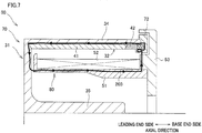
- FIG. 7 is a cross section of an induction heating roller 60 of the second embodiment of the present invention.
- FIG. 8(a) shows a fixing ring 72, viewed from the base end side in the axial direction. The fixing ring 72 will be described later.
- FIG. 8(b) is a cross section taken along VIII(b)-VIII(b) in FIG. 8(a) .
- the induction heating roller 60 of the second embodiment of the present invention includes a roller 70 and a heater 80.
- the roller 70 includes: the roller main body 31 including the outer cylindrical portion 34; the heat equalizing unit 32 including the heat equalizing member 41; and the fixing ring 72 made of carbon steel.
- the roller main body 31 is supported in a cantilever manner.
- the pressing member 42 of the roller 70 is made of non-magnetic material such as SUS. That is, the first magnetic member 46 is not provided. Furthermore, the second magnetic member 54 is not provided to the heater 80.
- a path 203 (see a bold line) passing through the fixing ring 72 made of carbon steel is formed as a path through which magnetic flux readily passes. If excessive eddy currents flow in the circumferential direction of the fixing ring 72 due to the magnetic flux passing through the fixing ring 72, excessive heat may be generated in the fixing ring 72. For this reason, the fixing ring 72 has the following configurations in order to mitigate heat generation in the fixing ring 72 by reducing eddy currents.
- the fixing ring 72 has high resistive portions 74.
- Each high resistive portion 74 is a portion of the fixing ring 72 in the circumferential direction.
- the high resistive portion 74 has an electric resistance higher than that of other portion in the circumferential direction.
- two high resistive portions 74 are provided.
- the high resistive portions 74 are portions of a ring main body 73 made of conductive material, which portions respectively have holes 75 with respect to the circumferential direction.
- Each hole 75 is, for example, a hole bored through the ring main body 73 in the axial direction and shaped like a slit extending in the radial direction (see FIG. 8(a) and (b) ).
- each high resistive portion 74 (strictly speaking, the cross-sectional area of each portion of the conductive ring main body 73) orthogonal to the circumferential direction is smaller than that of the portion other than the high resistive portions 74.
- the high resistive portions 74 therefore decrease the eddy currents flowing in the circumferential direction, to mitigate heat generation in the fixing ring 72.
- Each hole 75 is filled with an insulator 76. By filling the holes 75 with the insulators 76, a decrease in strength of high resistive portions 74 is mitigated.
- the insulator 76 is made of synthetic resin, for example, and is firmly attached to an inner circumferential surface 75a of the corresponding hole 75.
- each hole 75 is not particularly limited, as long as it reduces the cross-sectional area of the high resistive portions 74.
- each hole 75 may be a round hole, instead of the slit-shaped hole.
- each hole 75 does not have to be bored through the ring main body 73 in the axial direction. It may be bored through the ring main body 73 in the radial direction, for example. Still further, each hole 75 does not have to be a through hole bored through the ring main body 73.
- the number of the holes 75 is not limited to two.
- each high resistive portion 74 may have a notch or the like, instead of the hole 75.
- the fixing ring 72 is provided with the high resistive portions 74. Due to this, eddy currents flowing in the circumferential direction of the fixing ring 72 are reduced by the high resistive portions 74, and this makes it possible to mitigate heat generation in the fixing ring 72 provided to the induction heating roller 60.
- each high resistive portion 74 orthogonal to the circumferential direction is smaller, the electric resistance in the circumferential direction is higher at the high resistive portion 74.
- the high electric resistance in the circumferential direction of the fixing ring 72 reduces the eddy currents flowing therein.
- the one or more high resistive portions 74 each having a smaller cross-sectional area can be easily provided just by boring the hole(s) 75 in the ring main body 73 of the fixing ring 72.
- the insulator filling each hole 75 mitigates the decrease in strength of the fixing ring 72.
Landscapes
- Engineering & Computer Science (AREA)
- Textile Engineering (AREA)
- Physics & Mathematics (AREA)
- Mechanical Engineering (AREA)
- Thermal Sciences (AREA)
- Electromagnetism (AREA)
- General Induction Heating (AREA)
- Fixing For Electrophotography (AREA)
- Rolls And Other Rotary Bodies (AREA)
Abstract
Description
- The present invention relates to an induction heating roller and a spun yarn drawing device including one or more induction heating rollers.
-
Patent Literature 1 discloses an induction heating roller configured to heat yarns. The induction heating roller includes: a hollow roller main body; and a coil provided radially inward of the roller main body. As an alternating current flows through the coil, eddy currents are induced in the roller main body due to electromagnetic induction, and the roller main body is heated by Joule heating (that is, heat is generated in the roller main body by induction heating). The induction heating roller is supported in a cantilever manner so that yarns can be easily wound onto the roller. - Induction heating rollers each generally has difficulty in obtaining equal distribution of the surface temperature of the roller main body in its axial direction because heat generation therein is less likely to be equal in the axial direction and because heat is more likely to be dissipated at axial end portions of the roller main body to the outside. To deal with this, an induction heating roller described in
Patent Literature 2 includes a jacket chamber filled with a heating medium in a gas-liquid two-phase state, and the jacket chamber is provided in a roller main body so as to extend in an axial direction of the roller. As the jacket chamber functions as a heat pipe, the inequality in the distribution of the surface temperature of the roller main body in the axial direction is improved. -
- Patent Literature 1: Japanese Unexamined Patent Publication No.
H11(1999)-251052 - Patent Literature 2: Japanese Unexamined Patent Publication No.
2003-100437 - To provide such a jacket chamber in a roller main body, however, it is necessary to increase the thickness of the roller main body in its radial direction. This increases the heat capacity of the roller main body, which worsens the heating efficiency of the roller main body. In view of the above, the present inventors conceived an idea of providing a cylindrical heat equalizing member having a heat conductivity higher than that of the roller main body, in contact with an inner circumferential surface of the roller main body. This facilitates equalization in the distribution of the surface temperature of the roller main body because the heat equalizing member functions as a heat pipe. Furthermore, it is possible to efficiently heat the roller main body because the thickness of the roller main body is smaller and therefore the increase in the heat capacity is smaller.
- Now, reference is made to a case in which the heat equalizing member is applied to an induction heating roller supported in a cantilever manner, as described in
Patent Literature 1. In this case, the heat equalizing member is inserted into a space radially inside the roller main body through an opening of the roller main body, which is provided at its base-end-side portion in the axial direction ("axial base end portion"). Furthermore, a ring-like fixing member (hereinafter referred to as a "fixing ring") for fixing the roller main body and the heat equalizing member to each other is attached to the axial base end portion of the roller main body, for example. The fixing ring is arranged to extend further radially inward relative to the heat equalizing member in order to firmly fix the heat equalizing member provided radially inward of the roller main body. - As described above, at the axial end portions of the roller main body, it is more likely that heat is dissipated to the outside to cause a surface temperature drop. In view of the above, the present inventors used carbon steel, which is a ferromagnetic material, as a material of the fixing ring, based on the following grounds: the present inventors used such a fixing ring in order to improve the distribution of the surface temperature of the roller main body by facilitating the flow of magnetic flux through the fixing ring to facilitate the generation of eddy currents, thereby to increase the amount of heat generation at the base end portion of the roller main body. However, when this configuration was actually tested with a heater turned on, excessive heat was generated in the fixing ring and the temperature at the base end portion of the roller main body rose higher than that of its axially central portion, disadvantageously. That is, the present inventors found that: in the above configuration, magnetic flux excessively passed through the fixing ring extending further radially inward (toward the coil) relative to the roller main body, to induce eddy currents excessively, and therefore excessive heat was generated in the fixing ring.
- An object of the present invention is to mitigate heat generation in a fixing ring provided to an induction heating roller.
- In a first aspect of the present invention, an induction heating roller includes: a rotatable roller unit; and a heater including a coil provided radially inward of the roller unit. The roller unit includes: a roller main body including a cylindrical heating target configured to be heated by induction heating due to magnetic flux passing in an axial direction of the roller unit, the magnetic flux being generated by electric current flowing through the coil; a heat equalizing unit including a heat equalizing member which is in contact with an inner circumferential surface of the heating target, the heat equalizing member extending in the axial direction, and having a heat conductivity higher at least than that of the inner circumferential surface of the heating target; a fixing ring provided so as to be in contact with a first-side end portion of the heating target which is on a first side in the axial direction and with a first-side end portion of the heat equalizing unit which is on the first side in the axial direction, the fixing ring fixing the roller main body and the heat equalizing unit to each other; and a first magnetic member provided between the heating target and the coil in the radial direction, the first magnetic member being provided on the first side relative to a center of the heating target in the axial direction and on a second side relative to the fixing ring in the axial direction.
- In this aspect of the present invention, the fixing ring is provided so as to be in contact with the first-side end portion of the heating target and with the first-side end portion of the heat equalizing unit in the axial direction of the roller unit (hereinafter, simply referred to as an "axial direction"), and the fixing ring fixes the roller main body and the heat equalizing unit to each other. At least a part of the fixing ring is, in general, positioned closer to the coil than the heating target and the heat equalizing unit in the radial direction. Magnetic flux tends to, in nature, concentratedly flow into the shortest path, through which magnetic flux readily passes, among paths for magnetic flux, and therefore in the above configuration, magnetic flux is more likely to flow into the fixing ring. This increases the possibility that heat is generated in the fixing ring due to induction heating.
- To deal with this, in the above aspect of the present invention, the first magnetic member is provided radially inward of the heating target, and is provided on the first side relative to the axial center of the heating target in the axial direction and on the second side relative to the fixing ring in the axial direction. Thus, appropriately disposing the first magnetic member makes it possible to form a new path through which magnetic flux more readily passes than a path extending via the fixing ring. Due to this, as compared to the case in which no first magnetic member is provided, the amount of magnetic flux passing through the fixing ring can be reduced, leading to reduction of eddy currents generated in the fixing ring. Accordingly, it is possible to mitigate heat generation in the fixing ring provided to the induction heating roller.
- In a second aspect of the invention, the induction heating roller of the first aspect is arranged such that the heat equalizing member has a relative permeability lower than that of the fixing ring.
- In the above configuration in which the heat equalizing member has the lower relative permeability, magnetic flux is less likely to pass through the heat equalizing member, and this increases the likelihood that the magnetic flux concentratedly flows into the fixing ring. Even in this configuration, because the new path through which magnetic flux readily passes is created by the first magnetic member in the above aspect, it is possible to effectively decrease the amount of magnetic flux passing through the fixing ring.
- In a third aspect of the invention, the induction heating roller of the first or second aspect is arranged such that the first magnetic member is provided so as to correspond to a whole circumference of the fixing ring in a circumferential direction of the fixing ring.
- In this aspect, the inflow of magnetic flux into the fixing ring is further reduced as compared to the case in which the first magnetic member is provided only partially with respect to the circumferential direction of the fixing ring.
- In a fourth aspect of the invention, the induction heating roller of any of the first to third aspects is arranged such that the first magnetic member is in contact with the inner circumferential surface of the heating target.
- If the flow of magnetic flux is disturbed between the first magnetic member and the heating target, there is a possibility that the magnetic flux detours to flow into the fixing ring. As compared to the case in which the first magnetic member is not in contact with the heating target (i.e., the case in which there is a gap between the first magnetic member and the heating target), the above arrangement facilitates the flow of magnetic flux between the first magnetic member and the heating target, and therefore it is possible to reduce the amount of magnetic flux detouring to flow into the fixing ring.
- In a fifth aspect of the invention, the induction heating roller of any of the first to fourth aspects is arranged such that the first magnetic member is in contact with the heat equalizing member.
- As magnetic flux passes through the first magnetic member, the first magnetic member is also heated by induction heating. Because the first magnetic member is in contact with the heat equalizing member in this aspect, heat generated in the first magnetic member is transmitted to the heating target via the heat equalizing member. This makes it possible to efficiently heat the heating target.
- In a sixth aspect of the invention, the induction heating roller of any of the first to fifth aspects is arranged such that there is a gap between the first magnetic member and the fixing ring in the axial direction.
- In the above aspect, as compared to the case in which there is no gap between the first magnetic member and the fixing ring (i.e., the case in which the first magnetic member is in contact with the fixing ring), it is possible to reduce the transmission of heat, generated by eddy currents flowing in the first magnetic member, toward the fixing ring. This makes a temperature rise in the fixing ring smaller. Furthermore, due to the presence of the gap, magnetic flux is less likely to flow toward the fixing ring.
- In a seventh aspect of the invention, the induction heating roller of any of the first to sixth aspects is arranged such that the heat equalizing unit includes: a pressing member provided side by side on the first side of the heat equalizing member in the axial direction and configured to press the heat equalizing member; and a biasing member provided between the pressing member and the fixing ring in the axial direction and configured to bias the pressing member toward the second side in the axial direction, and such that the pressing member is provided to function as the first magnetic member.
- In the above aspect, the pressing member is biased in the axial direction, and by the biased pressing member, the heat equalizing member is pressed in the axial direction. This makes it possible to firmly fix the heat equalizing member in the axial direction. Furthermore, because the pressing member is provided to function as the first magnetic member, an increase in cost is smaller as compared to the case in which the first magnetic member and the pressing member are provided as different members.
- In an eighth aspect of the invention, the induction heating roller of any of the first to seventh aspects is arranged such that the heater includes a second magnetic member provided radially outward of the coil, the second magnetic member being provided so as to be opposed to the first magnetic member in the radial direction.
- In this aspect, the heater is provided with the second magnetic member. This makes it possible to form a path through which magnetic flux readily passes along the second magnetic member. This facilitates the flow of magnetic flux between the first and second magnetic members opposed to each other in the radial direction when the magnetic flux flows between the heater provided radially inside and the roller unit provided radially outside. Accordingly, it is possible to reliably reduce the amount of magnetic flux passing through the fixing ring.
- In a ninth aspect of the invention, the induction heating roller of the eighth aspect is arranged such that the second magnetic member is structured by a plurality of parts arranged in the circumferential direction of the fixing ring.
- In this aspect, the flow of the magnetic flux between the first magnetic member and the second magnetic member is further facilitated, as compared to the case in which the second magnetic member is provided to cover only a limited area with respect to the circumferential direction of the fixing ring.
- In a tenth aspect of the invention, the induction heating roller of the eighth or ninth aspect is arranged such that: the heater includes a third magnetic member provided adjacent to an end portion of the coil on the first side in the axial direction, the third magnetic member extending further radially outward relative to the coil; and the second magnetic member is provided in contact with the third magnetic member.
- In this aspect, magnetic flux generated by currents flowing through the coil is intentionally guided by the third magnetic member to the second magnetic member. Thus, the magnetic flux are reliably introduced into the second magnetic member.
- In an eleventh aspect of the invention, the induction heating roller of any of the first to tenth aspects is arranged such that the fixing ring has a relative permeability lower than that of the first magnetic member.
- In this aspect, the fixing ring has the lower relative permeability, and this makes it less likely that magnetic flux passes through the fixing ring, and therefore eddy currents are less likely to flow in the fixing ring. This makes the heat generation in the fixing ring further smaller.
- In a twelfth aspect of the present invention, an induction heating roller includes: a rotatable roller unit; and a heater including a coil provided radially inward of the roller unit. The roller unit includes: a roller main body including a cylindrical heating target configured to be heated by induction heating due to magnetic flux passing in an axial direction of the roller, the magnetic flux being generated by electric current flowing through the coil; a heat equalizing unit including a heat equalizing member which is in contact with an inner circumferential surface of the heating target, the heat equalizing member extending in the axial direction and having a heat conductivity higher at least than that of the inner circumferential surface of the heating target; and a fixing ring provided so as to be in contact with a first-side end portion of the heating target which is on a first side in the axial direction and with a first-side end portion of the heat equalizing unit which is on the first side in the axial direction, the fixing ring fixing the roller main body and the heat equalizing unit to each other. The fixing ring includes a high resistive portion provided at a part of the fixing ring with respect to its circumferential direction and configured to decrease eddy currents flowing in the circumferential direction.
- In this aspect, as same as in the first aspect, the fixing ring is arranged to extend further radially inward relative to the heating target and the heat equalizing unit, which increases the likelihood of inflow of magnetic flux into the fixing ring. This may cause a problem that the magnetic flux passing through the fixing ring induces eddy currents whirling in the circumferential direction of the fixing ring, to cause great heat generation in the fixing ring. To deal with this, in this aspect, the high resistive portion is provided at a part of the fixing ring in the circumferential direction, and the high resistive portion decreases the eddy currents flowing in the circumferential direction of the fixing ring. Accordingly, it is possible to mitigate heat generation in the fixing ring provided to the induction heating roller.
- In a thirteenth aspect of the invention, the induction heating roller of the twelfth aspect is arranged such that the high resistive portion has a cross-sectional area, which is orthogonal to the circumferential direction, smaller than that of a portion of the fixing ring other than the high resistive portion.
- In this aspect, because the cross-sectional area of the high resistive portion orthogonal to the circumferential direction is smaller, the electric resistance in the circumferential direction is higher at the high resistive portion. The high electric resistance in the circumferential direction of the fixing ring makes it possible to reduce the eddy currents.
- In a fourteenth aspect of the invention, the induction heating roller of the thirteenth aspect is arranged such that: the high resistive portion has a hole; and the high resistive portion has a cross-sectional area smaller than that of the portion of the fixing ring other than the high resistive portion, due to a presence of the hole.
- In this aspect, the high resistive portion with a smaller cross-sectional area is easily provided just by boring a hole at a part of the fixing ring.
- In a fifteenth aspect of the invention, the induction heating roller of the fourteenth aspect is arranged such that the hole is filled with an insulator.
- Providing a hollow hole at a part of the fixing ring in the circumferential direction may decrease the strength of the fixing ring at the high resistive portion. In this aspect, the insulator filling the hole mitigates such a decrease in strength of the fixing ring.
- In a sixteenth aspect of the invention, the induction heating roller of the twelfth aspect is arranged such that: the fixing ring includes a plurality of ring pieces which are separable in the circumferential direction; the ring pieces are connected to each other via insulators; and portions of the fixing ring in which the insulators are respectively provided in the circumferential direction function as the high resistive portion.
- In this aspect, due to the insulators interposed between the plurality of ring pieces, it is possible to reliably reduce the eddy currents from flowing while whirling in the circumferential direction of the fixing ring.
- In a seventeenth aspect of the invention, the induction heating roller of any of the first to sixteenth aspects is arranged such that: the roller main body is supported in a cantilever manner; and the fixing ring is provided, in the axial direction, at a base end portion of the heating target, which is the first-side end portion of the heating target.
- In the roller main body supported in a cantilever manner, a portion of the base end portion of the roller main body which is exposed to outside air is smaller than that of its leading end portion. Therefore, heat is less likely to be dissipated at the base end portion. For this reason, when heat is generated in the fixing ring provided to the base end portion of the heating target, the generated heat tends to be transmitted toward the leading end side of the heating target before being dissipated to the outside. The above tendency is more likely to cause a temperature gradient, in which the temperature is higher at the base end side in the axial direction of the heating target while the temperature is lower at the leading end side, resulting in the problem of poor distribution of temperature on the surface of the heating target. In this aspect, by mitigating the heat generation in the fixing ring provided to the base end portion of the heating target, the above-described temperature gradient is moderated, leading to improvement in the distribution of the temperature on the surface of the base end portion of the heating target.
- In an eighteenth aspect, a spun yarn drawing device includes the induction heating roller recited in any one of the first to seventeenth aspects, and the apparatus is arranged such that a plurality of yarns are wound onto an outer circumferential surface of the induction heating roller in a lined-up manner in the axial direction.
- In this aspect, it is possible to equalize the distribution of temperature of the roller surface, and to efficiently raise the temperature of the roller surface. This stabilizes the quality of the yarns wound onto the induction heating roller, to enable production of high-quality yarns.
-
- [
FIG. 1] FIG. 1 is a schematic diagram illustrating a spun yarn take-up machine including induction heating rollers of a first embodiment of the present invention. - [
FIG. 2] FIG. 2 is a cross section of one of the induction heating rollers. - [
FIG. 3] FIG. 3(a) and FIG. 3(b) include a perspective view and a side view of a heat equalizing unit and the like. - [
FIG. 4] FIG. 4 is an explanatory diagram showing a path through which magnetic flux readily passes. - [
FIG. 5] FIG. 5 is an explanatory diagram showing a path through which magnetic flux readily passes in the roller with a first magnetic member and a second magnetic member. - [
FIG. 6] FIG. 6 is a graph showing a temperature distribution on the induction heating roller in its axial direction. - [
FIG. 7] FIG. 7 is a diagram illustrating an induction heating roller of a second embodiment of the present invention. - [
FIG. 8 ] Each ofFIG. 8(a) and FIG. 8(b) is a diagram illustrating a fixing ring. - [
FIG. 9] FIG. 9 is a diagram illustrating a fixing ring of a modification of the second embodiment. - The following describes a first embodiment of the present invention with reference to
FIG. 1 to FIG. 6 . - First of all, with reference to
FIG. 1 , a description is given of the structure of a spun yarn take-upmachine 1 includinginduction heating rollers 20 of the first embodiment.FIG. 1 is a front view of the spun yarn take-upmachine 1. The description below is given on the premise that the up-down direction, front-back direction, and left-right direction shown inFIG. 1 are respectively the up-down direction, front-back direction, and left-right direction relative to the spun yarn take-upmachine 1. The spun yarn take-upmachine 1 is configured so that yarns Y spun out from aspinning apparatus 2 are drawn in a spunyarn drawing device 3 and the drawn yarns Y are wound up in ayarn winding apparatus 4. - The
spinning apparatus 2 is configured to produce yarns Y by continuously spinning out molten polymer such as nylon and polyester. To the yarns Y spun out from thespinning apparatus 2, oil is applied at anoil guide 10. The yarns Y are then sent to the spunyarn drawing device 3 via aguide roller 11. - The spun
yarn drawing device 3 is an apparatus for drawing the yarns Y and is provided below thespinning apparatus 2. The spunyarn drawing device 3 includesgodet rollers 21 to 25 housed in athermal insulation box 12. Thegodet rollers 21 to 25 are configured to be driven and rotated by respective motors. Each of thegodet rollers 21 to 25 is theinduction heating roller 20 heated by induction heating using a coil. Yarns Y are wound onto an outer circumferential surface of each of thegodet rollers 21 to 25. Thethermal insulation box 12 has, at a lower portion of its right side surface, aninlet 12a through which yarns Y are introduced into thethermal insulation box 12. Thethermal insulation box 12 further has, at an upper portion of its right side surface, anoutlet 12b through which yarns Y go out of thethermal insulation box 12. Yarns Y are wound onto each of thegodet rollers 21 to 25, in order from thelowermost godet roller 21, at a winding angle smaller than 360 degrees. - The lower three
godet rollers 21 to 23 are preheating rollers configured to preliminarily heat yarns Y before drawing them. The roller surface temperature of each of these rollers is arranged to be equal to or higher than the glass transition temperature of the yarns Y (e.g., on the order of 90 to 100 degrees centigrade). The upper twogodet rollers godet rollers 21 to 23 (e.g., on the order of 150 to 200 degrees centigrade). Furthermore, the yarn feeding speeds of the upper twogodet rollers godet rollers 21 to 23. - The yarns Y introduced into the
thermal insulation box 12 through theinlet 12a are, at first, preliminarily heated to a drawable temperature while being transferred by thegodet rollers 21 to 23. The preliminarily heated yarns Y are drawn due to the difference in yarn feeding speed between thegodet roller 23 and thegodet roller 24. The yarns Y are then further heated to a higher temperature while being transferred by thegodet rollers thermal insulation box 12 through theoutlet 12b. - The yarns Y drawn by the spun
yarn drawing device 3 are sent to theyarn winding apparatus 4 via aguide roller 13. Theyarn winding apparatus 4 is an apparatus for winding the yarns Y and is provided below the spunyarn drawing device 3. Theyarn winding apparatus 4 includes abobbin holder 14, acontact roller 15, and the like. Thebobbin holder 14 has a cylindrical shape extending in the front-back direction, and is driven and rotated by a motor, which is not illustrated. Bobbins B arranged side by side in an axial direction of thebobbin holder 14 are attached to thebobbin holder 14. Theyarn winding apparatus 4 is configured to wind yarns Y onto the bobbins B at the same time by rotating thebobbin holder 14, to produce packages P. Thecontact roller 15 is configured to come into contact with the surfaces of the packages P to adjust the shape of each package P by applying a predetermined contact pressure to each package P. - Next, the structure of each of the
induction heating rollers 20, which are used as thegodet rollers 21 to 25, will be described with reference toFIG. 2 andFIG. 3 .FIG. 2 is a cross section of eachinduction heating roller 20.FIG. 3(a) is a perspective view of aheat equalizing unit 32 and the like, which will be described later.FIG. 3(b) is a diagram showing aheat equalizing member 41 pressed by a pressingmember 42. A rollermain body 31 of theinduction heating roller 20 is supported in a cantilever manner by amotor 100 configured to rotate and drive the rollermain body 31. Hereinafter, a direction in which the rollermain body 31 extends (i.e., a left-right direction on the sheet ofFIG. 2 ) is referred to as an "axial direction" or "axially". In the present embodiment, the axial direction of the rollermain body 31 is identical with an axial direction of a roller unit 30 (which will be described later) and to an axial direction of a heat equalizing unit 32 (which will be described later). Relative to the rollermain body 31, a side closer to themotor 100 in the axial direction is referred to as a "base end side" (a first side in the present invention). A side opposite from the base end side is referred to as a "leading end side" (a second side in the present invention). Furthermore, a radial direction of the rollermain body 31 may be simply referred to as a "radial direction" or "radially". Still further, a circumferential direction of the rollermain body 31 may be simply referred to as a "circumferential direction". - The
induction heating roller 20 includes: therotatable roller unit 30; and aheater 50 provided radially inward of theroller unit 30. Theinduction heating roller 20 is configured to raise the temperature of an outer circumferential surface of theroller unit 30 by induction heating caused by acoil 52 provided in theheater 50, and thereby to heat yarns Y wound onto theroller unit 30. Theroller unit 30 is rotated and driven by themotor 100. Theheater 50 is fixed to a heater supporting portion (not illustrated) attached to themotor 100. That is, theroller unit 30 is configured to be rotatable but theheater 50 is configured to be non-rotatable. - To begin with, the
roller unit 30 will be described. Theroller unit 30 includes: the rollermain body 31; theheat equalizing unit 32; and a fixingring 33. The rollermain body 31 is a cylindrical member and is configured to be rotated and driven by themotor 100. Theheat equalizing unit 32 is provided radially inward of the rollermain body 31 and radially outward of thecoil 52. Theheat equalizing unit 32 is provided to equalize the temperature distribution on the rollermain body 31 in the axial direction. The fixingring 33 is attached to an axial base end portion (a base end portion in the axial direction) of the rollermain body 31. The fixingring 33 fixes the rollermain body 31 and theheat equalizing unit 32 to each other. Hereinafter, details of each of the components will be described. - The roller
main body 31 is, for example, made of carbon steel, which is magnetic and conductive material. The rollermain body 31 includes: an outer cylindrical portion 34 (a heating target in the present invention) with a cylindrical shape, which is provided radially outward of thecoil 52 and extends in the axial direction; acylindrical core portion 35 provided radially inward of thecoil 52; and anend face portion 36 connecting a leading end portion of the outercylindrical portion 34 to a leading end portion of thecore portion 35. The rollermain body 31 has an open end on the base end side. The outercylindrical portion 34, thecore portion 35, and theend face portion 36 are, for example, unitarily formed as a single member. Alternatively, at least two of the outercylindrical portion 34, thecore portion 35, and theend face portion 36 may be respectively formed by components different from each other. For example, the following configuration is possible: the outercylindrical portion 34 is formed by a first component; and thecore portion 35 and theend face portion 36 are formed by a second component. In this case, the first component and the second component are fixed to each other, for example, by welding, or fixed by a fixing member such as screws or the like. Note that the whole of the rollermain body 31 does not have to be made of one material (for example, of carbon steel mentioned above). That is, as long as the outercylindrical portion 34 and theend face portion 36 are made of magnetic and conductive material, the rest of the rollermain body 31 may be made of another material. Thecore portion 35 does not have to be made of magnetic material. Yarns Y are wound onto an outercircumferential surface 34a of the outercylindrical portion 34. The length of the outercircumferential surface 34a in the axial direction is, for example, 180 mm. Theheat equalizing unit 32 is in contact with an innercircumferential surface 34b of the outercylindrical portion 34. Thecore portion 35 has ashaft inserting hole 35a in which adrive shaft 101 of themotor 100 is inserted. Thedrive shaft 101 is fitted in theshaft inserting hole 35a, and thereby the rollermain body 31 is fixed to thedrive shaft 101. This allows the rollermain body 31 to be supported in a cantilever manner by themotor 100 and to be rotatable with thedrive shaft 101. Theend face portion 36 has, at its radially outer end portion, acontact surface 36a with which a leading end portion of theheat equalizing member 41 is in contact. Thecontact surface 36a is a tapered surface, which is sloped so that its thickness in the axial direction decreases toward radially outside. - The
heat equalizing unit 32 includes: theheat equalizing member 41, the pressingmember 42, and springs 43 (a biasing member in the present invention). Theheat equalizing member 41 is used to equalize the distribution of the surface temperature of the outercylindrical portion 34 of the rollermain body 31 in the axial direction. Theheat equalizing member 41 is a cylindrical member provided radially inward of the outercylindrical portion 34 of the rollermain body 31 and radially outward of thecoil 52. Theheat equalizing member 41 is pressed by the pressingmember 42 and by thesprings 43 toward the leading end side in the axial direction and radially outward, and due to this, theheat equalizing member 41 is fixed to the roller main body 31 (the details thereof will be described later.) - The
heat equalizing member 41 is a cylindrical member extending in the axial direction, and is, for example, made of C/C composite material (carbon fiber reinforced-carbon matrix-composite material), which is a composite material of carbon fiber reinforcement in a matrix of graphite. Theheat equalizing member 41 has a heat conductivity higher than that of the rollermain body 31 made of carbon steel (at least higher than that of the innercircumferential surface 34b of the outer cylindrical portion 34). Due to its higher heat conductivity, theheat equalizing member 41 has a function of equalizing the temperature distribution on the outercylindrical portion 34 in the axial direction. For example, the heat conductivity of carbon steel is 51.5 W/mk, while the heat conductivity of C/C composite material in the axial direction is 404 W/mk. Furthermore, theheat equalizing member 41 has a relative permeability lower than that of the rollermain body 31. For example, the relative permeability of carbon steel is 100 to 2000, while the relative permeability of C/C composite material is approximately 1. - The
heat equalizing member 41 is in contact with the innercircumferential surface 34b of the outercylindrical portion 34 of the rollermain body 31. Now an area of the outercircumferential surface 34a of the outercylindrical portion 34 with respect to the axial direction, onto which yarns Y are wound, is defined as a wound region R. Theheat equalizing member 41 is provided to cover the wound region R with respect to the axial direction. Furthermore, theheat equalizing member 41 is structured by a plurality ofheat equalizing pieces 44 separable with respect to the circumferential direction (seeFIG. 3(a) ). A base-end-side end face 44a and a leading-end-side end surface 44b of eachheat equalizing piece 44 are tapered. To be more specific, theend face 44a is arranged so that its radially outer edge is on the base end side relative to its radially inner edge, in the axial direction. Theend surface 44b is arranged so that its radially outer edge is on the leading end side relative to its radially inner edge, in the axial direction. Theend surface 44b is shaped to match with thecontact surface 36a of theend face portion 36 of the rollermain body 31. - The pressing
member 42 is biased by thesprings 43, and thereby to press theheat equalizing member 41 toward the leading end side in the axial direction and outward in the radial direction. The pressingmember 42 is a ring-like member (seeFIG. 3(a) ), and its outer diameter and inner diameter are substantially equal to those of theheat equalizing member 41, respectively. A leading-end-side end face 42a of the pressingmember 42 is a tapered pressing surface arranged so that its radially inner edge is on the leading end side in the axial direction relative to its radially outer edge. That is, theend face 42a is designed to match with the surface formed by the above-described base-end-side end faces 44a of theheat equalizing pieces 44. Eachspring 43 is in agap 45 between the pressingmember 42 and the fixingring 33 in the axial direction. Abase end portion and a leading end portion of thespring 43 are in contact with the fixingring 33 and the pressingmember 42, respectively, and thespring 43 is compressed in the axial direction. Due to this, eachspring 43 biases, with its restoring force, the pressingmember 42 toward the leading end side in the axial direction. Because the pressingmember 42 is biased by thesprings 43, theheat equalizing member 41 is pressed toward the leading end side in the axial direction (see an arrow in the left-right direction on the sheet ofFIG. 3(b) ). Simultaneously, due to thetapered end face 42a, theheat equalizing member 41 is pressed also outward in the radial direction (see arrows in the up-down direction on the sheet ofFIG. 3(b) ). As a result, outercircumferential surfaces 44c of theheat equalizing pieces 44 are reliably brought into contact with the innercircumferential surface 34b of the outercylindrical portion 34 of the rollermain body 31. It should be noted that the number ofsprings 43 is not particularly limited. Instead of the one ormore springs 43, a rubber elastic member or the like may be used as a biasing member biasing the pressingmember 42. - The fixing
ring 33 is a ring-like member provided at an axial base end portion of the outercylindrical portion 34 of the rollermain body 31. The fixingring 33 is, for example, made of carbon steel as same as the rollermain body 31. That is, the relative permeability of the above-describedheat equalizing member 41 is lower than the relative permeability of the fixingring 33. The fixingring 33 extends further radially outward relative to the outercylindrical portion 34 of the rollermain body 31, and extends further radially inward relative to theheat equalizing unit 32. A radially inner end portion of the fixingring 33 is closer to thecoil 52 than the outercylindrical portion 34 and than theheat equalizing unit 32 in the radial direction. That is, the distance between the fixingring 33 and thecoil 52 in the radial direction is shorter than the distance between theheat equalizing unit 32 and thecoil 52 in the radial direction. The fixingring 33 is provided in contact with the axial base end portion of the rollermain body 31 and with an axial base end portion of theheat equalizing unit 32. Specifically, as shown inFIG. 3(b) , the fixingring 33 has a surroundingportion 33a. The surroundingportion 33a is shaped so as to surround a part of the rollermain body 31 and a part of theheat equalizing unit 32 with respect to three sides thereof, i.e., the radially outer side, the radially inner side, and the base end side in the axial direction. Thus, the base end portion of the outercylindrical portion 34 of the rollermain body 31 and a base end portion of the pressingmember 42 are surrounded, with the result that the rollermain body 31 and theheat equalizing unit 32 are fixed. Furthermore, the fixingring 33 has a recessedportion 33b to accommodate thesprings 43. The recessedportion 33b provides thegap 45 between the pressingmember 42 and the fixingring 33 in the axial direction. - The following describes the
heater 50. Theheater 50 includes: abobbin member 51, thecoil 52, and aflange 53. In theheater 50, thecoil 52 is wound around thebobbin member 51 extending in the axial direction. An axial base end portion of thebobbin member 51 is attached to theflange 53. - The
bobbin member 51 is a cylindrical member provided radially inward of the outercylindrical portion 34 of the rollermain body 31 and radially outward of thecore portion 35. Thebobbin member 51 is, for example, made of carbon steel as same as the rollermain body 31. Thecoil 52 is wound around an outer periphery of thebobbin member 51. - The
coil 52 is used to heat the rollermain body 31 by induction heating. Thecoil 52, which is wound around thebobbin member 51, is provided inward of the outercylindrical portion 34 of the rollermain body 31 and outward of thecore portion 35. As an alternating voltage is applied to thecoil 52, an alternating current flows through thecoil 52, to generate an alternating magnetic field. - The
flange 53 is a disc-like member. Theflange 53 has, at its radially central portion, a throughhole 53a so that theflange 53 and thedrive shaft 101 of themotor 100 do not interfere with each other. Theflange 53 is, for example, made of carbon steel as same as the rollermain body 31. Theflange 53 is provided at an axial base end portion of the heater 40. The axial base end portion of thebobbin member 51 is attached to theflange 53. Theflange 53 is fixed to the heater supporting portion (not shown) of themotor 100. Theflange 53 extends further radially outward relative to thecoil 52. A radially outer end portion of theflange 53 is positioned on the base end side in the axial direction relative to the fixingring 33 of theroller unit 30, so as to cover the fixingring 33. There is a gap between theflange 53 and the fixingring 33, to prevent interference between theflange 53 of theheater 50 configured not to rotate and the fixingring 33 of theroller unit 30 configured to rotate. - As an alternating voltage is applied to the
coil 52 in eachinduction heating roller 20, an alternating current flows through thecoil 52, to generate an alternating magnetic field, and magnetic flux passes through the outercylindrical portion 34 of the rollermain body 31 in the axial direction. This induces eddy currents flowing in the rollermain body 31 in the circumferential direction, and the outercylindrical portion 34 is heated by Joule heating. Theinduction heating rollers 20 each generally has difficulty in obtaining equal distribution of the surface temperature of the rollermain body 31 because heat generation therein is less likely to be equal in the axial direction and because the heat is more likely to be dissipated at the axial end portions of the rollermain body 31 to the outside. For this reason, theheat equalizing member 41 is used to equalize the distribution of temperature on the outercylindrical portion 34 in the axial direction. As described above, theheat equalizing member 41 has a lower relative permeability. Therefore, the magnetic flux is less likely to pass through theheat equalizing member 41, and heat is less likely to be generated in theheat equalizing member 41. - As described above, at the axial end portions of the roller
main body 31, it is more likely that heat is dissipated to the outside, to cause a surface temperature drop. In view of the above, the present inventors used carbon steel, which is a ferromagnetic material, as a material of the fixingring 33 in order to improve the distribution of the surface temperature of the roller main body by facilitating the flow of magnetic flux through the fixingring 33 to facilitate the generation of eddy currents, thereby to increase the amount of heat generation at the base end portion of the rollermain body 31. Magnetic flux tends to, in nature, concentratedly flow through the shortest path, through which magnetic flux readily passes, among paths for magnetic flux. Because of this, the present inventors selected at first SUS (Steel Use Stainless), which is a non-magnetic material, as a material of the pressingmember 42 so that magnetic flux passes through the fixingring 33 rather than through the pressingmember 42. However, when this configuration was actually tested with theheater 50 turned on, excessive heat was generated in the fixingring 33 and the temperature at the base end portion of the rollermain body 31 rose higher than that of its axially central portion, disadvantageously. - The above-described problem will be schematically described with reference to
FIG. 4 . In theinduction heating roller 20, apath 201 through which magnetic flux readily passes is formed by the members made of ferromagnetic carbon steel. (It should be noted that arrows are depicted just to improve visibility. The direction of the magnetic flux changes when the direction of the current flowing through thecoil 52 changes.) To be more specific, thepath 201 extends through thebobbin member 51, theflange 53, the fixingring 33, the outercylindrical portion 34 of the rollermain body 31, and theend face portion 36. Because magnetic flux tends to, in nature, pass near a surface of a ferromagnetic material ("skin effect"), thepath 201 is formed so as to pass on or near the surfaces of the above-described members. - If the magnetic flux concentratedly flows through the
path 201, eddy currents are excessively induced in the fixingring 33, leading to a large amount of heat generation in the fixingring 33. In particular, magnetic flux passing through the fixingring 33 in the axial direction induces eddy currents whirling in the circumferential direction of the fixingring 33. This makes the heat generation more significant. Furthermore, the fixingring 33 is provided at the base end portion of theroller unit 30 supported in a cantilever manner, and a portion of the fixingring 33 which faces the outside is smaller than that of a leading end portion of theroller unit 30. Therefore, the heat is less likely to be dissipated from the fixingring 33. For this reason, the heat generated in the fixingring 33 is more likely to be transmitted toward a leading-end-side portion of the outercylindrical portion 34 of the rollermain body 31 before it is dissipated to the outside. The present inventors considered that this tends to cause a temperature gradient, in which the higher temperatures are observed at a base-end-side portion of the outercylindrical portion 34 while lower temperatures are observed at the leading-end-side portion thereof, resulting in the problem of poor distribution of temperature on the outercircumferential surface 34a of the outercylindrical portion 34. - To mitigate heat generation in the fixing
ring 33, eachinduction heating roller 20 has the below-described configuration. Specifically, a description will be given, referring back toFIG. 2 andFIG. 3 . - In the first embodiment, each
induction heating roller 20 has the following configuration so as to provide another path through which magnetic flux readily passes, which is different from the above-described path 201 (seeFIG. 4 ). First of all, the pressingmember 42 provided to press theheat equalizing member 41 is made of carbon steel, which is a ferromagnetic material, as same as the rollermain body 31 and the like. Hereinbelow, the pressingmember 42 is referred to as a firstmagnetic member 46. In other words, the pressingmember 42 is used as the firstmagnetic member 46. As shown inFIG. 2 , the firstmagnetic member 46 is provided between the outercylindrical portion 34 of the rollermain body 31 and thecoil 52 in the radial direction, and is provided on the base end side relative to the center of the outercylindrical portion 34 in the axial direction and on the leading end side relative to the fixingring 33. The firstmagnetic member 46 is in contact with the innercircumferential surface 34b of the outercylindrical portion 34 and in contact with theheat equalizing member 41. There is thegap 45 between the firstmagnetic member 46 and the fixingring 33 in the axial direction. It is preferable that the firstmagnetic member 46 is provided so as to correspond to the whole circumference in the circumferential direction, as shown inFIG. 3(a) , for example. However, the present invention is not limited to this. For example, the firstmagnetic member 46 may be structured by parts separable in the circumferential direction and arranged with spaces interposed between them. - The
heater 50 includes a secondmagnetic member 54. The secondmagnetic member 54 is made of carbon steel, as same as the firstmagnetic member 46. As shown inFIG. 2 , the secondmagnetic member 54 is provided radially outward of thecoil 52, and is provided so as to be opposed to the firstmagnetic member 46 in the radial direction. The secondmagnetic member 54 is attached to the flange 53 (a third magnetic member of the present invention), and is in contact with theflange 53. The secondmagnetic member 54 is provided so that the secondmagnetic member 54 and the firstmagnetic member 46, which is provided to therotating roller unit 30, do not interfere with each other. It is preferable that, as shown inFIG. 3(a) , for example, the secondmagnetic member 54 is structured by parts arranged in the circumferential direction with spaces interposed between them. However, the present invention is not limited to this. - In each induction heating roller having the above-described configuration, a new path through which magnetic flux readily passes is formed by the first
magnetic member 46 and the secondmagnetic member 54. This will be schematically described with reference toFIG. 5 . - As shown in
FIG. 5 , a path 202 (see a bold line inFIG. 5 ) through which magnetic flux readily passes is formed aside from thepath 201 by the firstmagnetic member 46 and the secondmagnetic member 54. To be more specific, thepath 202 passes through thebobbin member 51, theflange 53, the secondmagnetic member 54, a part of the fixingring 33, the firstmagnetic member 46, and the outercylindrical portion 34, and theend face portion 36 of the rollermain body 31. Now, among the paths through which magnetic flux can pass, reference is made in particular to paths formed in theroller unit 30. Of these, the path passing through the first magnetic member 46 (see the path 202) is shorter than the path passing through the base end portion of the rollermain body 31 and through the fixing ring 33 (see the path 201). Due to this, magnetic flux is more readily to pass through thepath 202 than thepath 201, and this reduces the amount of magnetic flux passing through the fixingring 33. This reduces generation of eddy currents in the fixingring 33. - In the above-described configuration, the inflow of magnetic flux toward the fixing
ring 33 is further reduced due to the following two reasons. The first reason is that the firstmagnetic member 46 is in contact with the innercircumferential surface 34b of the outercylindrical portion 34. This facilitates the flow of magnetic flux between the firstmagnetic member 46 and the outercylindrical portion 34, and this decreases the possibility that the magnetic flux detours to flow into the fixingring 33. The second reason is that there is thegap 45 between the firstmagnetic member 46 and the fixingring 33 in the axial direction. This decreases the possibility that the magnetic flux passing through the firstmagnetic member 46 flows into the fixingring 33. - Because the magnetic flux passes through the first
magnetic member 46, the firstmagnetic member 46 is also heated by induction heating. As described above, the firstmagnetic member 46 is in contact with the innercircumferential surface 34b of the outercylindrical portion 34 and in contact with theheat equalizing member 41. Due to this, heat generated in the first magnetic member is directly transmitted to the outercylindrical portion 34, or is transmitted to the outercylindrical portion 34 via theheat equalizing member 41. Consequently, the outercylindrical portion 34 is efficiently heated. - With reference to
FIG. 6 , the following describes a change in distribution of temperature on the outercircumferential surface 34a of the outercylindrical portion 34 of the rollermain body 31 in the axial direction, due to the presence or absence of the firstmagnetic member 46 and the secondmagnetic member 54. The present inventors observed the distribution of the temperature on the outercircumferential surface 34a in the axial direction for two cases with and without the first and secondmagnetic members member 42 is made of non-magnetic material, and no secondmagnetic member 54 is provided.) In both cases, the temperature at a center of the outercircumferential surface 34a in the axial direction was set to 150 degrees centigrade. Furthermore, the operation speed (circumferential speed) of theroller unit 30 was set to 5500 m/min. Under these conditions, comparison was made for the distribution of the temperature on the outercircumferential surface 34a in the axial direction, between the case in which the firstmagnetic member 46 and the secondmagnetic member 54 are provided ("Example") and the case in which these magnetic members are not provided ("Comparative Example"). - The result of the comparison is shown in
FIG. 6 . The horizontal axis represents the distance of a point on the outercircumferential surface 34a from a leading end of the rollermain body 31. That is, the smaller the distance is, the closer the point is to the leading end of the rollermain body 31. The larger the distance is, the closer the point is to a base end of the rollermain body 31. As described above, the length of the outercircumferential surface 34a in the axial direction is 180 mm. The vertical axis represents the difference in the surface temperature from the temperature at the center of the outercircumferential surface 34a in the axial direction (hereinafter "axially central portion"), that is, at the point at the above distance of 90 mm. In Comparative Example (see a broken line inFIG. 6 ), the larger the distance from the leading end of the rollermain body 31 is (that is, the closer the point is to the fixingring 33 on the base end side), the higher the surface temperature is. At some points, there were observed 1 degrees centigrade or more differences from the surface temperature at the axially central portion. Meanwhile, in Example (see a solid line inFIG. 6 ), it was observed that the temperatures at the axial base end portion of the outercircumferential surface 34a were somewhat lower than the temperature at the axially central portion. Furthermore, the difference in the surface temperature between the axial base end portion and the axially central portion of the outercircumferential surface 34a was within 1 degrees centigrade at every point. Thus, the temperature gradient at the axial base end portion of the outercircumferential surface 34a has been improved. It was confirmed that the heat generation in the fixingring 33 was reduced by providing the firstmagnetic member 46 and the secondmagnetic member 54 thereby to form the path 202 (seeFIG. 5 ) through which magnetic flux more readily passes than thepath 201. - As described above, the first
magnetic member 46 is provided radially inward of the outercylindrical portion 34, and is provided on the base end side relative to the axial center of the outercylindrical portion 34 in the axial direction and on the leading end side relative to the fixingring 33 in the axial direction. Thus, appropriately disposing the firstmagnetic member 46 makes it possible to form thenew path 202 through which magnetic flux more readily passes than thepath 201 extending via the fixingring 33. Due to this, as compared to the case in which no firstmagnetic member 46 is provided, the amount of magnetic flux passing through the fixingring 33 can be reduced, leading to reduction of eddy currents generated in the fixingring 33. In this way, it is possible to mitigate heat generation in the fixingring 33 provided to theinduction heating roller 20. - Furthermore, in the configuration in which: the
heat equalizing member 41 has a low relative permeability; and this increases the likelihood of concentrated inflow of magnetic flux into the fixingring 33, it is possible to effectively decrease the amount of magnetic flux passing through the fixingring 33 by forming thepath 202, through which magnetic flux readily passes, by the firstmagnetic member 46. - Furthermore, in the configuration in which the first
magnetic member 46 is provided so as to correspond to the whole circumference in the circumferential direction, it is possible to further reduce the inflow of magnetic flux into the fixingring 33, as compared to the case in which the firstmagnetic member 46 is provided only partially with respect to the circumferential direction. - Furthermore, the first
magnetic member 46 is in contact with the innercircumferential surface 34b of the outercylindrical portion 34. As compared to the case in which there is a gap between the firstmagnetic member 46 and the outercylindrical portion 34, the above arrangement facilitates the flow of magnetic flux between the firstmagnetic member 46 and the outercylindrical portion 34, and therefore it is possible to reduce the amount of magnetic flux detouring to flow into the fixingring 33. - Furthermore, the first
magnetic member 46 is in contact with theheat equalizing member 41. This allows heat generated in the firstmagnetic member 46 by induction heating to be transmitted to the outercylindrical portion 34 via theheat equalizing member 41. This makes it possible to efficiently heat the outercylindrical portion 34. - Furthermore, there is the
gap 45 between the firstmagnetic member 46 and the fixingring 33. Due to this, as compared to the case in which the firstmagnetic member 46 is in contact with the fixingring 33, it is possible to reduce the transmission of heat, generated by eddy currents flowing in the firstmagnetic member 46, toward the fixingring 33. This makes a temperature rise in the fixingring 33 smaller. Furthermore, due to the presence of thegap 45, magnetic flux is less likely to flow toward the fixingring 33. - Furthermore, the pressing member 42 (the first magnetic member 46) is biased in the axial direction and thereby the
heat equalizing member 41 is pressed by the pressingmember 42. This allows theheat equalizing member 41 to be firmly fixed in the axial direction. Furthermore, because the pressingmember 42 is provided to function as the firstmagnetic member 46, an increase in cost is smaller as compared to the case in which the firstmagnetic member 46 and the pressingmember 42 are provided as different members. - Furthermore, because the second
magnetic member 54 is provided to theheater 50, a path through which magnetic flux readily passes can be formed along the secondmagnetic member 54. This facilitates the flow of magnetic flux between the firstmagnetic member 46 and the secondmagnetic member 54 opposed to each other in the radial direction when the magnetic flux flows between theheater 50 provided radially inside and theroller unit 30 provided radially outside. Accordingly, it is possible to reliably reduce the amount of magnetic flux passing through the fixingring 33. - Furthermore, in the configuration in which the second
magnetic member 54 is structured by parts arranged in the circumferential direction, the flow of the magnetic flux between the firstmagnetic member 46 and the secondmagnetic member 54 is further facilitated, as compared to the case in which the secondmagnetic member 54 is provided to cover only a limited area with respect to the circumferential direction. - Furthermore, generated magnetic flux is intentionally guided by the
flange 53 functioning as the third magnetic member to the secondmagnetic member 54. This allows the magnetic flux to be reliably introduced into the secondmagnetic member 54. - Furthermore, in the configuration in which the roller
main body 31 is supported in a cantilever manner, heat generation in the fixingring 33 provided to the base end portion is mitigated, thereby to moderate the above-described temperature gradient, leading to improvement in the distribution of the temperature on the axial base end portion of the outercircumferential surface 34a of the outercylindrical portion 34. - Furthermore, in the spun
yarn drawing device 3 including the above-describedinduction heating rollers 20, it is possible to equalize the distribution of temperature on roller surfaces, and to efficiently raise the temperature on the roller surfaces. This stabilizes the quality of yarns Y wound onto theinduction heating rollers 20, to enable production of high-quality yarns. - The following will describe modifications of the first embodiment. Components which are equivalent to or the same as those in the first embodiment are given the same reference numerals, and the descriptions thereof are not repeated, if appropriate.
- (1) In the first embodiment, the fixing
ring 33 is made of ferromagnetic carbon steel. However, the present invention is not limited to this. That is, the fixingring 33 may have a relative permeability lower than that of the firstmagnetic member 46 made of carbon steel. For example, the fixingring 33 may be made of a non-magnetic material such as SUS (Steel Use Stainless) having a relative permeability of approximately 1. In this arrangement, magnetic flux is less likely to pass through the fixingring 33, and therefore eddy currents are less likely to flow through the fixingring 33. Accordingly, heat generation in the fixingring 33 is further reduced. Also in this arrangement, due to the presence of the firstmagnetic member 46, a path for magnetic flux is formed, such that the magnetic flux readily passes through the outercylindrical portion 34 of the rollermain body 31. This mitigates the deterioration of efficiency in induction heating of the outercylindrical portion 34. - (2) In the first embodiment, the second
magnetic member 54 is in contact with theflange 53. However, the present invention is not limited to this. That is, there may be a gap between the secondmagnetic member 54 and theflange 53. Also in this arrangement, magnetic flux can readily pass between the secondmagnetic member 54 and theflange 53 when the gap is small. - (3) In the first embodiment, the second
magnetic member 54 is provided to theheater 50. However, the present invention is not limited to this. That is, as long as the firstmagnetic member 46 is provided to theroller unit 30, the path through which magnetic flux readily passes without passing through the fixingring 33 is formed. This reduces the amount of magnetic flux flowing into the fixingring 33, to mitigate heat generation in the fixingring 33. - (4) In the first embodiment, the first
magnetic member 46 is biased by thesprings 43. However, the present invention is not limited to this. The firstmagnetic member 46 does not have to be biased in the axial direction. Furthermore, thegap 45 may not exist between the firstmagnetic member 46 and the fixingring 33. When the firstmagnetic member 46 is not biased by thesprings 43, the fixingring 33 does not have to be shaped so as to surround the part of the rollermain body 31 and the part of theheat equalizing unit 32. - (5) In the first embodiment, the pressing
member 42 functions as the firstmagnetic member 46. However, the present invention is not limited to this. The firstmagnetic member 46 may be provided as a member different from the pressingmember 42. Also in this arrangement, the pressingmember 42 does not have to be biased by thesprings 43, as described above. The firstmagnetic member 46 does not have to be in contact with the outercylindrical portion 34 and/or with theheat equalizing member 41. - (6) In the first embodiment, the roller
main body 31 is supported in a cantilever manner. However, the present invention is not limited to this. That is, each induction heating roller may be supported at its both ends. Also in this arrangement, there is a possibility that excessive heat is generated in the fixingring 33 by induction heating, at an end portion of the roller in the axial direction to which the fixingring 33 is provided. Also in this arrangement, providing the firstmagnetic member 46 and the like to form a path through which magnetic flux readily passes, thereby to reduce the inflow of magnetic flux into the fixingring 33, to reduce the generation of eddy currents, is effective to mitigate heat generation in the fixingring 33. - (7) In the first embodiment, the
induction heating rollers 20 configured to heat yarns Y have been described. However, the application ofinduction heating rollers 20 is not limited to heating yarns Y. Each induction heating roller may be used to heat objects other than yarns Y, for example, to heat sheet-like materials such as films, paper, non-woven fabric, sheet resin, and the like, or to heat toner or the like placed in the form of an image on a sheet, which is provided in a photocopier and the like. - The following describes a second embodiment of the present invention with reference to
FIG. 7 ,FIG. 8(a), and FIG. 8(b) . Components which are equivalent to or the same as those in the first embodiment are given the same reference numerals, and the descriptions thereof are not repeated, if appropriate. -
FIG. 7 is a cross section of aninduction heating roller 60 of the second embodiment of the present invention.FIG. 8(a) shows a fixingring 72, viewed from the base end side in the axial direction. The fixingring 72 will be described later.FIG. 8(b) is a cross section taken along VIII(b)-VIII(b) inFIG. 8(a) . - The
induction heating roller 60 of the second embodiment of the present invention includes aroller 70 and aheater 80. Theroller 70 includes: the rollermain body 31 including the outercylindrical portion 34; theheat equalizing unit 32 including theheat equalizing member 41; and the fixingring 72 made of carbon steel. The rollermain body 31 is supported in a cantilever manner. - Now, a description will be given of differences between the
induction heating roller 60 and theinduction heating roller 20 of the first embodiment. The pressingmember 42 of theroller 70 is made of non-magnetic material such as SUS. That is, the firstmagnetic member 46 is not provided. Furthermore, the secondmagnetic member 54 is not provided to theheater 80. - Due to the above-described arrangement, in the
induction heating roller 60, a path 203 (see a bold line) passing through the fixingring 72 made of carbon steel is formed as a path through which magnetic flux readily passes. If excessive eddy currents flow in the circumferential direction of the fixingring 72 due to the magnetic flux passing through the fixingring 72, excessive heat may be generated in the fixingring 72. For this reason, the fixingring 72 has the following configurations in order to mitigate heat generation in the fixingring 72 by reducing eddy currents. - As shown in
FIG. 8(a) and (b) , the fixingring 72 has highresistive portions 74. Each highresistive portion 74 is a portion of the fixingring 72 in the circumferential direction. The highresistive portion 74 has an electric resistance higher than that of other portion in the circumferential direction. InFIG. 8(a) , two highresistive portions 74 are provided. The highresistive portions 74 are portions of a ringmain body 73 made of conductive material, which portions respectively haveholes 75 with respect to the circumferential direction. Eachhole 75 is, for example, a hole bored through the ringmain body 73 in the axial direction and shaped like a slit extending in the radial direction (seeFIG. 8(a) and (b) ). Because of this, the cross-sectional area of each high resistive portion 74 (strictly speaking, the cross-sectional area of each portion of the conductive ring main body 73) orthogonal to the circumferential direction is smaller than that of the portion other than the highresistive portions 74. This makes the electric resistance at the highresistive portions 74 in the circumferential direction higher than that at the portion other than the highresistive portions 74. The highresistive portions 74 therefore decrease the eddy currents flowing in the circumferential direction, to mitigate heat generation in the fixingring 72. Eachhole 75 is filled with aninsulator 76. By filling theholes 75 with theinsulators 76, a decrease in strength of highresistive portions 74 is mitigated. Theinsulator 76 is made of synthetic resin, for example, and is firmly attached to an innercircumferential surface 75a of the correspondinghole 75. - The shape and the like of each
hole 75 is not particularly limited, as long as it reduces the cross-sectional area of the highresistive portions 74. For example, eachhole 75 may be a round hole, instead of the slit-shaped hole. Furthermore, eachhole 75 does not have to be bored through the ringmain body 73 in the axial direction. It may be bored through the ringmain body 73 in the radial direction, for example. Still further, eachhole 75 does not have to be a through hole bored through the ringmain body 73. Moreover, the number of theholes 75 is not limited to two. Furthermore, each highresistive portion 74 may have a notch or the like, instead of thehole 75. - As described above, the fixing
ring 72 is provided with the highresistive portions 74. Due to this, eddy currents flowing in the circumferential direction of the fixingring 72 are reduced by the highresistive portions 74, and this makes it possible to mitigate heat generation in the fixingring 72 provided to theinduction heating roller 60. - Furthermore, because the cross-sectional area of each high
resistive portion 74 orthogonal to the circumferential direction is smaller, the electric resistance in the circumferential direction is higher at the highresistive portion 74. The high electric resistance in the circumferential direction of the fixingring 72 reduces the eddy currents flowing therein. - Furthermore, the one or more high
resistive portions 74 each having a smaller cross-sectional area can be easily provided just by boring the hole(s) 75 in the ringmain body 73 of the fixingring 72. - Furthermore, the insulator filling each
hole 75 mitigates the decrease in strength of the fixingring 72. - The following will describe modifications of the second embodiment. Components which are equivalent to or the same as those in the second embodiment are given the same reference numerals, and the descriptions thereof are not repeated, if appropriate.
- (1) In the second embodiment, each high
resistive portion 74 of the fixingring 72 has thehole 75 bored through the ringmain body 73, but the present invention is not limited to this. For example, as shown inFIG. 9 , a fixingring 90 may be structured by a plurality ofring pieces 91 which are separable in the circumferential direction and are connected to one another byinsulators 92. Eachinsulator 92 is made of synthetic resin, for example, and is provided between the corresponding tworing pieces 91 and firmly attached to thering pieces 91. Thus, theinsulators 92 interposed between thering pieces 91 reliably reduces eddy currents from flowing while whirling in the circumferential direction of the fixingring 90. In this modification, portions of the fixingring 90 in the circumferential direction, at which theinsulators 92 are provided, correspond to the "high resistive portion" in the present invention. - (2) Also in the second embodiment, the roller
main body 31 is supported in a cantilever manner. However, the present invention is not limited to this. That is, eachinduction heating roller 60 may be supported at its both ends. Also in this arrangement, it is possible to mitigate heat generation in the fixingring 72 by providing the at least one highresistive portion 74 in the fixingring 72 to reduce generation of eddy currents. - (3) Each
induction heating roller 60 may be configured to heat objects other than yarns Y, as same as eachinduction heating roller 20 described in the first embodiment. That is, eachinduction heating roller 60 may be configured to heat sheet-like materials such as films, paper, non-woven fabric, sheet resin, and the like, or to heat toner or the like placed in the form of an image on a sheet, which is provided in a photocopier and the like. -
- 3:
- spun yarn drawing device
- 20:
- induction heating roller
- 30:
- roller unit
- 31:
- roller main body
- 32:
- heat equalizing unit
- 33:
- fixing ring
- 34:
- outer cylindrical portion (heating target)
- 34b:
- inner circumferential surface
- 41:
- heat equalizing member
- 42:
- pressing member
- 42a
- end face
- 43:
- spring (biasing member)
- 44a:
- end face
- 45:
- gap
- 46:
- first magnetic member
- 50:
- heater
- 52:
- coil
- 53:
- flange (third magnetic member)
- 54:
- second magnetic member
- 60:
- induction heating roller
- 72:
- fixing ring
- 74:
- high resistive portion
- 75:
- hole
- 76:
- insulator
- 90:
- fixing ring
- 91:
- ring piece
- 92:
- insulator
- Y:
- yarn
Claims (18)
- An induction heating roller comprising:a rotatable roller unit; anda heater including a coil provided radially inward of the roller unit,the roller unit comprising:a roller main body including a cylindrical heating target configured to be heated by induction heating due to magnetic flux passing in an axial direction of the roller unit, the magnetic flux being generated by electric current flowing through the coil;a heat equalizing unit including a heat equalizing member which is in contact with an inner circumferential surface of the heating target, the heat equalizing member extending in the axial direction and having a heat conductivity higher at least than that of the inner circumferential surface of the heating target;a fixing ring provided so as to be in contact with a first-side end portion of the heating target which is on a first side in the axial direction and with a first-side end portion of the heat equalizing unit which is on the first side in the axial direction, the fixing ring fixing the roller main body and the heat equalizing unit to each other; anda first magnetic member provided between the heating target and the coil in the radial direction, the first magnetic member being provided on the first side relative to a center of the heating target in the axial direction and on a second side relative to the fixing ring in the axial direction.
- The induction heating roller according to claim 1, wherein the heat equalizing member has a relative permeability lower than that of the fixing ring.
- The induction heating roller according to claim 1 or 2, wherein the first magnetic member is provided so as to correspond to a whole circumference of the fixing ring in a circumferential direction of the fixing ring.
- The induction heating roller according to any one of claims 1 to 3, wherein the first magnetic member is in contact with the inner circumferential surface of the heating target.
- The induction heating roller according to any one of claims 1 to 4, wherein the first magnetic member is in contact with the heat equalizing member.
- The induction heating roller according to any one of claims 1 to 5, wherein there is a gap between the first magnetic member and the fixing ring in the axial direction.
- The induction heating roller according to any one of claims 1 to 6,
wherein the heat equalizing unit includes:a pressing member provided side by side on the first side of the heat equalizing member in the axial direction and configured to press the heat equalizing member; anda biasing member provided between the pressing member and the fixing ring in the axial direction and configured to bias the pressing member toward the second side in the axial direction, andwherein the pressing member is provided to function as the first magnetic member. - The induction heating roller according to any one of claims 1 to 7, wherein the heater includes a second magnetic member provided radially outward of the coil, the second magnetic member being provided so as to be opposed to the first magnetic member in the radial direction.
- The induction heating roller according to claim 8, wherein the second magnetic member is structured by a plurality of parts arranged in the circumferential direction of the fixing ring.
- The induction heating roller according to claim 8 or 9,
wherein the heater includes a third magnetic member provided adjacent to an end portion of the coil on the first side in the axial direction, the third magnetic member extending further radially outward relative to the coil, and
wherein the second magnetic member is provided in contact with the third magnetic member. - The induction heating roller according to any one of claims 1 to 10, wherein the fixing ring has a relative permeability lower than that of the first magnetic member.
- An induction heating roller comprising:a rotatable roller unit; anda heater including a coil provided radially inward of the roller unit,wherein the roller unit comprises:a roller main body including a cylindrical heating target configured to be heated by induction heating due to magnetic flux passing in an axial direction of the roller unit, the magnetic flux being generated by electric current flowing through the coil;a heat equalizing unit including a heat equalizing member which is in contact with an inner circumferential surface of the heating target, the heat equalizing member extending in the axial direction and having a heat conductivity higher at least than that of the inner circumferential surface of the heating target; anda fixing ring provided so as to be in contact with a first-side end portion of the heating target which is on a first side in the axial direction and with a first-side end portion of the heat equalizing unit which is on the first side in the axial direction, the fixing ring fixing the roller main body and the heat equalizing unit to each other, andwherein the fixing ring comprises a high resistive portion provided at a part of the fixing ring with respect to its circumferential direction and configured to decrease eddy currents flowing in the circumferential direction.
- The induction heating roller according to claim 12, wherein the high resistive portion has a cross-sectional area, which is orthogonal to the circumferential direction, smaller than that of a portion of the fixing ring other than the high resistive portion.
- The induction heating roller according to claim 13, wherein the high resistive portion has a hole to make the cross-sectional area of the high resistive portion smaller than that of the portion other than the high resistive portion.
- The induction heating roller according to claim 14, wherein the hole is filled with an insulator.
- The induction heating roller according to claim 12,
wherein the fixing ring includes a plurality of ring pieces which are separable in the circumferential direction,
wherein the ring pieces are connected to each other via insulators, and
wherein portions of the fixing ring in which the insulators are respectively provided in the circumferential direction function as the high resistive portion. - The induction heating roller according to any one of claims 1 to 16,
wherein the roller main body is supported in a cantilever manner, and
wherein the fixing ring is provided, in the axial direction, at a base end portion of the heating target, which is the first-side end portion of the heating target. - A spun yarn drawing device comprising the induction heating roller recited in any one of claims 1 to 17,
wherein a plurality of yarns are wound onto an outer circumferential surface of the induction heating roller in a lined-up manner in the axial direction.
Applications Claiming Priority (3)
| Application Number | Priority Date | Filing Date | Title |
|---|---|---|---|
| JP2017200810 | 2017-10-17 | ||
| JP2018030816 | 2018-02-23 | ||
| PCT/JP2018/033795 WO2019077914A1 (en) | 2017-10-17 | 2018-09-12 | Induction heating roller and spun yarn drawing device |
Publications (3)
| Publication Number | Publication Date |
|---|---|
| EP3700302A1 true EP3700302A1 (en) | 2020-08-26 |
| EP3700302A4 EP3700302A4 (en) | 2021-08-18 |
| EP3700302B1 EP3700302B1 (en) | 2025-09-03 |
Family
ID=66173695
Family Applications (1)
| Application Number | Title | Priority Date | Filing Date |
|---|---|---|---|
| EP18869072.1A Active EP3700302B1 (en) | 2017-10-17 | 2018-09-12 | Induction heating roller and spun yarn drawing device |
Country Status (5)
| Country | Link |
|---|---|
| EP (1) | EP3700302B1 (en) |
| JP (1) | JP6857744B2 (en) |
| CN (1) | CN111194577B (en) |
| TW (1) | TWI744553B (en) |
| WO (1) | WO2019077914A1 (en) |
Cited By (1)
| Publication number | Priority date | Publication date | Assignee | Title |
|---|---|---|---|---|
| EP3917282A1 (en) | 2020-05-27 | 2021-12-01 | TMT Machinery, Inc. | Induction heating roller and spun yarn drawing device |
Families Citing this family (1)
| Publication number | Priority date | Publication date | Assignee | Title |
|---|---|---|---|---|
| CN118979311B (en) * | 2024-10-22 | 2025-03-11 | 江苏恒力化纤股份有限公司 | A magnetic roller for spinning and a spinning method |
Family Cites Families (18)
| Publication number | Priority date | Publication date | Assignee | Title |
|---|---|---|---|---|
| US4208560A (en) * | 1974-10-16 | 1980-06-17 | Barmag Barmer Maschinenfabrik Ag | Inductively heated godet |
| JPS54157354A (en) * | 1978-06-02 | 1979-12-12 | Teijin Ltd | Induction heat generating roller |
| JPS60136375U (en) * | 1984-12-28 | 1985-09-10 | 特殊電機株式会社 | induction heating roller |
| JPH09127810A (en) * | 1995-10-27 | 1997-05-16 | Minolta Co Ltd | Induction heating fixing device |
| JP3853509B2 (en) | 1998-03-03 | 2006-12-06 | トクデン株式会社 | Induction heating roller device |
| JP4903327B2 (en) | 2001-09-21 | 2012-03-28 | トクデン株式会社 | Induction heating roller device |
| CN101040074A (en) * | 2004-10-14 | 2007-09-19 | 苏拉有限及两合公司 | Godets for guiding, heating and conveying the filaments |
| CN201119037Y (en) * | 2007-11-26 | 2008-09-17 | 严南根 | Inductance quick heating roller |
| JP2010015695A (en) * | 2008-07-01 | 2010-01-21 | Sumitomo Electric Ind Ltd | Induction heating device of rotary roll, and heating processing device |
| EP2664428B1 (en) * | 2012-05-16 | 2016-03-23 | UHLMANN PAC-SYSTEME GmbH & Co. KG | Sealing roller |
| JP6406829B2 (en) * | 2014-02-10 | 2018-10-17 | トクデン株式会社 | Induction heating roller device and induction coil temperature detection mechanism |
| JP6306931B2 (en) * | 2014-04-23 | 2018-04-04 | トクデン株式会社 | Induction heating roller device |
| CN204046852U (en) * | 2014-08-29 | 2014-12-24 | 上海联净电子科技有限公司 | A kind of electromagnetic induction heating roller |
| DE102015108635A1 (en) * | 2015-02-19 | 2016-08-25 | Ritter Elektronik Gmbh | Galetteneinheit with an induction coil assembly for heating without magnetic flux conductive internals |
| JP6909659B2 (en) * | 2016-08-25 | 2021-07-28 | Tmtマシナリー株式会社 | Induction heating roller |
| TWM550526U (en) * | 2017-01-13 | 2017-10-11 | Tomy Precision Mechanical Co Ltd | Electromagnetic heating roller device |
| CN206461796U (en) * | 2017-01-24 | 2017-09-01 | 上海联净电子科技有限公司 | Collector ring and the Electromechanic heating roller including it |
| CN206461797U (en) * | 2017-01-24 | 2017-09-01 | 上海联净电子科技有限公司 | Terminal box and the Electromechanic heating roller including it |
-
2018
- 2018-09-12 JP JP2019549153A patent/JP6857744B2/en active Active
- 2018-09-12 CN CN201880065455.8A patent/CN111194577B/en active Active
- 2018-09-12 WO PCT/JP2018/033795 patent/WO2019077914A1/en not_active Ceased
- 2018-09-12 EP EP18869072.1A patent/EP3700302B1/en active Active
- 2018-09-26 TW TW107133774A patent/TWI744553B/en active
Cited By (1)
| Publication number | Priority date | Publication date | Assignee | Title |
|---|---|---|---|---|
| EP3917282A1 (en) | 2020-05-27 | 2021-12-01 | TMT Machinery, Inc. | Induction heating roller and spun yarn drawing device |
Also Published As
| Publication number | Publication date |
|---|---|
| TWI744553B (en) | 2021-11-01 |
| WO2019077914A1 (en) | 2019-04-25 |
| JP6857744B2 (en) | 2021-04-14 |
| EP3700302B1 (en) | 2025-09-03 |
| JPWO2019077914A1 (en) | 2020-11-05 |
| EP3700302A4 (en) | 2021-08-18 |
| CN111194577A (en) | 2020-05-22 |
| CN111194577B (en) | 2022-02-22 |
| TW201918116A (en) | 2019-05-01 |
Similar Documents
| Publication | Publication Date | Title |
|---|---|---|
| US4005302A (en) | Inductively heated drawroll | |
| JP6909659B2 (en) | Induction heating roller | |
| EP3700302B1 (en) | Induction heating roller and spun yarn drawing device | |
| EP3758444B1 (en) | Induction heating roller and spun yarn take-up machine | |
| EP3700300B1 (en) | Induction heating roller and spun yarn drawing device | |
| EP3700301B1 (en) | Induction heating roller and spun yarn drawing device | |
| JP4221227B2 (en) | Godet | |
| EP3917282A1 (en) | Induction heating roller and spun yarn drawing device | |
| EP3758445A1 (en) | Heating roller and spun yarn drawing device | |
| JP4887979B2 (en) | Induction heating roller device |
Legal Events
| Date | Code | Title | Description |
|---|---|---|---|
| STAA | Information on the status of an ep patent application or granted ep patent |
Free format text: STATUS: THE INTERNATIONAL PUBLICATION HAS BEEN MADE |
|
| PUAI | Public reference made under article 153(3) epc to a published international application that has entered the european phase |
Free format text: ORIGINAL CODE: 0009012 |
|
| STAA | Information on the status of an ep patent application or granted ep patent |
Free format text: STATUS: REQUEST FOR EXAMINATION WAS MADE |
|
| 17P | Request for examination filed |
Effective date: 20200414 |
|
| AK | Designated contracting states |
Kind code of ref document: A1 Designated state(s): AL AT BE BG CH CY CZ DE DK EE ES FI FR GB GR HR HU IE IS IT LI LT LU LV MC MK MT NL NO PL PT RO RS SE SI SK SM TR |
|
| AX | Request for extension of the european patent |
Extension state: BA ME |
|
| DAV | Request for validation of the european patent (deleted) | ||
| DAX | Request for extension of the european patent (deleted) | ||
| A4 | Supplementary search report drawn up and despatched |
Effective date: 20210715 |
|
| RIC1 | Information provided on ipc code assigned before grant |
Ipc: H05B 6/14 20060101AFI20210709BHEP Ipc: D02J 1/22 20060101ALI20210709BHEP Ipc: F16C 13/00 20060101ALI20210709BHEP |
|
| STAA | Information on the status of an ep patent application or granted ep patent |
Free format text: STATUS: EXAMINATION IS IN PROGRESS |
|
| 17Q | First examination report despatched |
Effective date: 20221014 |
|
| P01 | Opt-out of the competence of the unified patent court (upc) registered |
Effective date: 20230426 |
|
| GRAP | Despatch of communication of intention to grant a patent |
Free format text: ORIGINAL CODE: EPIDOSNIGR1 |
|
| STAA | Information on the status of an ep patent application or granted ep patent |
Free format text: STATUS: GRANT OF PATENT IS INTENDED |
|
| INTG | Intention to grant announced |
Effective date: 20250513 |
|
| RIC1 | Information provided on ipc code assigned before grant |
Ipc: F16C 41/00 20060101ALI20250505BHEP Ipc: D02J 13/00 20060101ALI20250505BHEP Ipc: D01D 10/02 20060101ALI20250505BHEP Ipc: F16C 13/00 20060101ALI20250505BHEP Ipc: D02J 1/22 20060101ALI20250505BHEP Ipc: D01D 5/16 20060101ALI20250505BHEP Ipc: H05B 6/14 20060101AFI20250505BHEP |
|
| GRAS | Grant fee paid |
Free format text: ORIGINAL CODE: EPIDOSNIGR3 |
|
| GRAA | (expected) grant |
Free format text: ORIGINAL CODE: 0009210 |
|
| STAA | Information on the status of an ep patent application or granted ep patent |
Free format text: STATUS: THE PATENT HAS BEEN GRANTED |
|
| AK | Designated contracting states |
Kind code of ref document: B1 Designated state(s): AL AT BE BG CH CY CZ DE DK EE ES FI FR GB GR HR HU IE IS IT LI LT LU LV MC MK MT NL NO PL PT RO RS SE SI SK SM TR |
|
| REG | Reference to a national code |
Ref country code: GB Ref legal event code: FG4D |
|
| REG | Reference to a national code |
Ref country code: CH Ref legal event code: EP |
|
| REG | Reference to a national code |
Ref country code: DE Ref legal event code: R096 Ref document number: 602018085324 Country of ref document: DE |
|
| REG | Reference to a national code |
Ref country code: CH Ref legal event code: U11 Free format text: ST27 STATUS EVENT CODE: U-0-0-U10-U11 (AS PROVIDED BY THE NATIONAL OFFICE) Effective date: 20251001 |
|
| REG | Reference to a national code |
Ref country code: IE Ref legal event code: FG4D |
|
| PGFP | Annual fee paid to national office [announced via postgrant information from national office to epo] |
Ref country code: DE Payment date: 20250925 Year of fee payment: 8 |
|
| REG | Reference to a national code |
Ref country code: NL Ref legal event code: MP Effective date: 20250903 |
|
| PG25 | Lapsed in a contracting state [announced via postgrant information from national office to epo] |
Ref country code: NO Free format text: LAPSE BECAUSE OF FAILURE TO SUBMIT A TRANSLATION OF THE DESCRIPTION OR TO PAY THE FEE WITHIN THE PRESCRIBED TIME-LIMIT Effective date: 20251203 |
|
| REG | Reference to a national code |
Ref country code: LT Ref legal event code: MG9D |
|
| PG25 | Lapsed in a contracting state [announced via postgrant information from national office to epo] |
Ref country code: FI Free format text: LAPSE BECAUSE OF FAILURE TO SUBMIT A TRANSLATION OF THE DESCRIPTION OR TO PAY THE FEE WITHIN THE PRESCRIBED TIME-LIMIT Effective date: 20250903 |
|
| PG25 | Lapsed in a contracting state [announced via postgrant information from national office to epo] |
Ref country code: HR Free format text: LAPSE BECAUSE OF FAILURE TO SUBMIT A TRANSLATION OF THE DESCRIPTION OR TO PAY THE FEE WITHIN THE PRESCRIBED TIME-LIMIT Effective date: 20250903 |
|
| PG25 | Lapsed in a contracting state [announced via postgrant information from national office to epo] |
Ref country code: GR Free format text: LAPSE BECAUSE OF FAILURE TO SUBMIT A TRANSLATION OF THE DESCRIPTION OR TO PAY THE FEE WITHIN THE PRESCRIBED TIME-LIMIT Effective date: 20251204 |
|
| PGFP | Annual fee paid to national office [announced via postgrant information from national office to epo] |
Ref country code: CH Payment date: 20251001 Year of fee payment: 8 |
|
| PG25 | Lapsed in a contracting state [announced via postgrant information from national office to epo] |
Ref country code: SE Free format text: LAPSE BECAUSE OF FAILURE TO SUBMIT A TRANSLATION OF THE DESCRIPTION OR TO PAY THE FEE WITHIN THE PRESCRIBED TIME-LIMIT Effective date: 20250903 |
|
| PG25 | Lapsed in a contracting state [announced via postgrant information from national office to epo] |
Ref country code: LV Free format text: LAPSE BECAUSE OF FAILURE TO SUBMIT A TRANSLATION OF THE DESCRIPTION OR TO PAY THE FEE WITHIN THE PRESCRIBED TIME-LIMIT Effective date: 20250903 |
|
| PG25 | Lapsed in a contracting state [announced via postgrant information from national office to epo] |
Ref country code: BG Free format text: LAPSE BECAUSE OF FAILURE TO SUBMIT A TRANSLATION OF THE DESCRIPTION OR TO PAY THE FEE WITHIN THE PRESCRIBED TIME-LIMIT Effective date: 20250903 Ref country code: PL Free format text: LAPSE BECAUSE OF FAILURE TO SUBMIT A TRANSLATION OF THE DESCRIPTION OR TO PAY THE FEE WITHIN THE PRESCRIBED TIME-LIMIT Effective date: 20250903 |
|
| PG25 | Lapsed in a contracting state [announced via postgrant information from national office to epo] |
Ref country code: RS Free format text: LAPSE BECAUSE OF FAILURE TO SUBMIT A TRANSLATION OF THE DESCRIPTION OR TO PAY THE FEE WITHIN THE PRESCRIBED TIME-LIMIT Effective date: 20251203 |
|
| PG25 | Lapsed in a contracting state [announced via postgrant information from national office to epo] |
Ref country code: ES Free format text: LAPSE BECAUSE OF FAILURE TO SUBMIT A TRANSLATION OF THE DESCRIPTION OR TO PAY THE FEE WITHIN THE PRESCRIBED TIME-LIMIT Effective date: 20250903 |
|
| REG | Reference to a national code |
Ref country code: AT Ref legal event code: MK05 Ref document number: 1834758 Country of ref document: AT Kind code of ref document: T Effective date: 20250903 |
|
| PG25 | Lapsed in a contracting state [announced via postgrant information from national office to epo] |
Ref country code: NL Free format text: LAPSE BECAUSE OF FAILURE TO SUBMIT A TRANSLATION OF THE DESCRIPTION OR TO PAY THE FEE WITHIN THE PRESCRIBED TIME-LIMIT Effective date: 20250903 |
|
| PG25 | Lapsed in a contracting state [announced via postgrant information from national office to epo] |
Ref country code: SM Free format text: LAPSE BECAUSE OF FAILURE TO SUBMIT A TRANSLATION OF THE DESCRIPTION OR TO PAY THE FEE WITHIN THE PRESCRIBED TIME-LIMIT Effective date: 20250903 |
|
| PG25 | Lapsed in a contracting state [announced via postgrant information from national office to epo] |
Ref country code: AT Free format text: LAPSE BECAUSE OF FAILURE TO SUBMIT A TRANSLATION OF THE DESCRIPTION OR TO PAY THE FEE WITHIN THE PRESCRIBED TIME-LIMIT Effective date: 20250903 |
|
| PG25 | Lapsed in a contracting state [announced via postgrant information from national office to epo] |
Ref country code: RO Free format text: LAPSE BECAUSE OF FAILURE TO SUBMIT A TRANSLATION OF THE DESCRIPTION OR TO PAY THE FEE WITHIN THE PRESCRIBED TIME-LIMIT Effective date: 20250903 Ref country code: IT Free format text: LAPSE BECAUSE OF FAILURE TO SUBMIT A TRANSLATION OF THE DESCRIPTION OR TO PAY THE FEE WITHIN THE PRESCRIBED TIME-LIMIT Effective date: 20250903 |
|
| PG25 | Lapsed in a contracting state [announced via postgrant information from national office to epo] |
Ref country code: IS Free format text: LAPSE BECAUSE OF FAILURE TO SUBMIT A TRANSLATION OF THE DESCRIPTION OR TO PAY THE FEE WITHIN THE PRESCRIBED TIME-LIMIT Effective date: 20260103 |
|
| PG25 | Lapsed in a contracting state [announced via postgrant information from national office to epo] |
Ref country code: CZ Free format text: LAPSE BECAUSE OF FAILURE TO SUBMIT A TRANSLATION OF THE DESCRIPTION OR TO PAY THE FEE WITHIN THE PRESCRIBED TIME-LIMIT Effective date: 20250903 Ref country code: PT Free format text: LAPSE BECAUSE OF FAILURE TO SUBMIT A TRANSLATION OF THE DESCRIPTION OR TO PAY THE FEE WITHIN THE PRESCRIBED TIME-LIMIT Effective date: 20260105 |
|
| PG25 | Lapsed in a contracting state [announced via postgrant information from national office to epo] |
Ref country code: SK Free format text: LAPSE BECAUSE OF FAILURE TO SUBMIT A TRANSLATION OF THE DESCRIPTION OR TO PAY THE FEE WITHIN THE PRESCRIBED TIME-LIMIT Effective date: 20250903 Ref country code: EE Free format text: LAPSE BECAUSE OF FAILURE TO SUBMIT A TRANSLATION OF THE DESCRIPTION OR TO PAY THE FEE WITHIN THE PRESCRIBED TIME-LIMIT Effective date: 20250903 |
|
| PG25 | Lapsed in a contracting state [announced via postgrant information from national office to epo] |
Ref country code: LU Free format text: LAPSE BECAUSE OF NON-PAYMENT OF DUE FEES Effective date: 20250912 |
|
| REG | Reference to a national code |
Ref country code: BE Ref legal event code: MM Effective date: 20250930 |
|
| REG | Reference to a national code |
Ref country code: DE Ref legal event code: R097 Ref document number: 602018085324 Country of ref document: DE |
|
| PG25 | Lapsed in a contracting state [announced via postgrant information from national office to epo] |
Ref country code: MC Free format text: LAPSE BECAUSE OF FAILURE TO SUBMIT A TRANSLATION OF THE DESCRIPTION OR TO PAY THE FEE WITHIN THE PRESCRIBED TIME-LIMIT Effective date: 20250903 Ref country code: LT Free format text: LAPSE BECAUSE OF FAILURE TO SUBMIT A TRANSLATION OF THE DESCRIPTION OR TO PAY THE FEE WITHIN THE PRESCRIBED TIME-LIMIT Effective date: 20250903 |
|
| PG25 | Lapsed in a contracting state [announced via postgrant information from national office to epo] |
Ref country code: DK Free format text: LAPSE BECAUSE OF FAILURE TO SUBMIT A TRANSLATION OF THE DESCRIPTION OR TO PAY THE FEE WITHIN THE PRESCRIBED TIME-LIMIT Effective date: 20250903 |
|
| PLBE | No opposition filed within time limit |
Free format text: ORIGINAL CODE: 0009261 |
|
| STAA | Information on the status of an ep patent application or granted ep patent |
Free format text: STATUS: NO OPPOSITION FILED WITHIN TIME LIMIT |
|
| REG | Reference to a national code |
Ref country code: CH Ref legal event code: L10 Free format text: ST27 STATUS EVENT CODE: U-0-0-L10-L00 (AS PROVIDED BY THE NATIONAL OFFICE) Effective date: 20260715 |
|
| PG25 | Lapsed in a contracting state [announced via postgrant information from national office to epo] |
Ref country code: BE Free format text: LAPSE BECAUSE OF NON-PAYMENT OF DUE FEES Effective date: 20250930 Ref country code: IE Free format text: LAPSE BECAUSE OF NON-PAYMENT OF DUE FEES Effective date: 20250912 |
|
| PG25 | Lapsed in a contracting state [announced via postgrant information from national office to epo] |
Ref country code: FR Free format text: LAPSE BECAUSE OF NON-PAYMENT OF DUE FEES Effective date: 20251103 |
|
| 26N | No opposition filed |
Effective date: 20260604 |