EP3700270B1 - Control information sending method, detection method, network device, and terminal - Google Patents
Control information sending method, detection method, network device, and terminal Download PDFInfo
- Publication number
- EP3700270B1 EP3700270B1 EP18868199.3A EP18868199A EP3700270B1 EP 3700270 B1 EP3700270 B1 EP 3700270B1 EP 18868199 A EP18868199 A EP 18868199A EP 3700270 B1 EP3700270 B1 EP 3700270B1
- Authority
- EP
- European Patent Office
- Prior art keywords
- cce
- occupied
- control information
- frequency domain
- rbs
- Prior art date
- Legal status (The legal status is an assumption and is not a legal conclusion. Google has not performed a legal analysis and makes no representation as to the accuracy of the status listed.)
- Active
Links
Images



Classifications
-
- H—ELECTRICITY
- H04—ELECTRIC COMMUNICATION TECHNIQUE
- H04L—TRANSMISSION OF DIGITAL INFORMATION, e.g. TELEGRAPHIC COMMUNICATION
- H04L27/00—Modulated-carrier systems
- H04L27/26—Systems using multi-frequency codes
- H04L27/2601—Multicarrier modulation systems
- H04L27/2602—Signal structure
-
- H—ELECTRICITY
- H04—ELECTRIC COMMUNICATION TECHNIQUE
- H04L—TRANSMISSION OF DIGITAL INFORMATION, e.g. TELEGRAPHIC COMMUNICATION
- H04L5/00—Arrangements affording multiple use of the transmission path
- H04L5/003—Arrangements for allocating sub-channels of the transmission path
- H04L5/0053—Allocation of signalling, i.e. of overhead other than pilot signals
-
- H—ELECTRICITY
- H04—ELECTRIC COMMUNICATION TECHNIQUE
- H04L—TRANSMISSION OF DIGITAL INFORMATION, e.g. TELEGRAPHIC COMMUNICATION
- H04L5/00—Arrangements affording multiple use of the transmission path
- H04L5/0091—Signalling for the administration of the divided path, e.g. signalling of configuration information
- H04L5/0094—Indication of how sub-channels of the path are allocated
-
- H—ELECTRICITY
- H04—ELECTRIC COMMUNICATION TECHNIQUE
- H04W—WIRELESS COMMUNICATION NETWORKS
- H04W72/00—Local resource management
- H04W72/20—Control channels or signalling for resource management
-
- H—ELECTRICITY
- H04—ELECTRIC COMMUNICATION TECHNIQUE
- H04W—WIRELESS COMMUNICATION NETWORKS
- H04W72/00—Local resource management
- H04W72/20—Control channels or signalling for resource management
- H04W72/23—Control channels or signalling for resource management in the downlink direction of a wireless link, i.e. towards a terminal
-
- H—ELECTRICITY
- H04—ELECTRIC COMMUNICATION TECHNIQUE
- H04W—WIRELESS COMMUNICATION NETWORKS
- H04W72/00—Local resource management
- H04W72/30—Resource management for broadcast services
-
- H—ELECTRICITY
- H04—ELECTRIC COMMUNICATION TECHNIQUE
- H04L—TRANSMISSION OF DIGITAL INFORMATION, e.g. TELEGRAPHIC COMMUNICATION
- H04L5/00—Arrangements affording multiple use of the transmission path
- H04L5/003—Arrangements for allocating sub-channels of the transmission path
- H04L5/0048—Allocation of pilot signals, i.e. of signals known to the receiver
-
- H—ELECTRICITY
- H04—ELECTRIC COMMUNICATION TECHNIQUE
- H04W—WIRELESS COMMUNICATION NETWORKS
- H04W56/00—Synchronisation arrangements
- H04W56/001—Synchronization between nodes
Definitions
- the present disclosure relates to the field of communication technology, in particular to a control information transmission method, a control information detection method, a network device and a User Equipment (UE).
- a control information transmission method a control information detection method
- a network device a network device
- UE User Equipment
- a control channel needs to occupy the entire system bandwidth, as shown in FIG. 1 .
- a UE needs to detect the entire system bandwidth, mainly resulting in the following problems. 1) Because the UE needs to detect the entire system bandwidth, the detection complexity of the control information may increase dramatically when the system bandwidth is relatively large. 2) The UE needs to be provided with a large bandwidth for the reception of the control information, so it is adverse to the flexible configuration of the bandwidth for the UE and the access of a small-bandwidth UE.
- one method is to divide a bandwidth available for the control channel within N available Orthogonal Frequency Division Multiplexing (OFDM) systems into M control sub-bands or control resource sets.
- OFDM Orthogonal Frequency Division Multiplexing
- a multi-beam design is adopted so as to improve the coverage performance.
- a plurality of Synchronization Signal (SS) blocks i.e., Physical Broadcast Channel (PBCH) blocks, is used for the synchronization of UEs.
- PBCH Physical Broadcast Channel
- Each SS block corresponds to one beam.
- the control resource set for the transmission of some public system information (similar to System Information Blocks (SIBs) in a Long Term Evolution (LTE) system) is defined as a public control resource set.
- SIBs System Information Blocks
- LTE Long Term Evolution
- EP 2 854 455 A1 concerns a method for transmitting downlink control information, a detecting method, a base station and a UE.
- the detecting method includes: the UE detects downlink control information beared by ePDCCH in a resource block according to a resource block set and pre-defined information configured by the base station; wherein the pre-defined information at least includes one of the followings: sub-carrier position information detected in the resource block set, enhanced control channel unit information detected in the resource block set, a mapping mode of the ePDCCH, aggregation level configuration information detected in the resource block set, the amount of candidate set corresponding to the detected aggregation level in the resource block set and a downlink control information format.
- US 2013/201975 A1 concerns techniques for systems that support DMRS-based transmissions, that may allow such systems to at least partially utilize resources in the center six RBs of subframes 0 and 5 for DMRS-based transmissions (e.g., EPDCCH), while avoiding collision with Primary Synchronization Signal (PSS), Secondary Synchronization Signal (SSS) or Physical Broadcast Channel (PBCH).
- PSS Primary Synchronization Signal
- SSS Secondary Synchronization Signal
- PBCH Physical Broadcast Channel
- Non-patent literature 3GPP draft, R1-1717952, titled “Discussion on search space design” discusses about CORESET configuration, nested structure and multi-beam operation for NR-PDCCH.
- the present invention concerns a control information transmission method according to claim 1, a control information detection method according to claim 13, a network device according to claim 14, and a user equipment according to claim 15.
- An object of the present disclosure is to provide a control information transmission method, a control information detection method, a network device and a UE, so as to map a control resource set to same time-domain resources as a plurality of symbols occupied by SS blocks, thereby to reduce the quantity of time-frequency resources occupied during a beam scanning operation, improve the scheduling flexibility of the UE, and reduce the detection complexity of the UE.
- the control resource set for transmitting the control information may be mapped to the at least one RB adjacent to the RB occupied by the SS block in accordance with the predetermined mapping mode, and then the predetermined mapping mode may be transmitted to the UE and the control information may be transmitted to the UE on the at least one RB occupied by the control resource set.
- control information transmission method which includes the following steps.
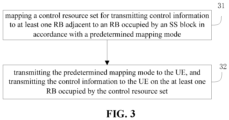
- Step 31 mapping a control resource set for transmitting control information to at least one RB adjacent to an RB occupied by an SS block in accordance with a predetermined mapping mode.
- the control resource set may be used for an initial access process of a user or transmit public information (including one of scheduling system information, paging information, power control information or any other public broadcast information).
- the control resource set may also be called as public control resource set.
- the term "public control resource set” defined herein is merely used for description, but shall not be used to limit functions of the control resource set.
- Step 32 transmitting the predetermined mapping mode to the UE, and transmitting the control information to the UE on the at least one RB occupied by the control resource set.
- Step 31 may include mapping the control resource set for transmitting the control information to at least one RB adjacent to an RB occupied by a PSS in the SS block and to at least one RB adjacent to an RB occupied by a PBCH in the SS block in accordance with the predetermined mapping mode.
- the at least one RB adjacent to the RB occupied by the PSS may include at least one RB at a same time domain as, and at a different frequency domain from, the RB occupied by the PSS.
- the at least one RB at the same time domain as, and at the different frequency domain from, the RB occupied by the PSS may include a first CCE consisting of N consecutive RBs at the same time domain as the RB occupied by the PSS and at a first frequency domain, and a second CCE consisting of N consecutive RBs at the same time domain as the RB occupied by the PSS and at a second frequency domain.
- the at least one RB adjacent to the RB occupied by the PBCH may include at least one RB at a same time domain as, and at a different frequency domain from, the RB occupied by the PBCH.
- the at least one RB at the same time domain as, and at the different frequency domain from, the RB occupied by the PBCH may include a third CCE consisting of N consecutive RBs at the same time domain as the RB occupied by the PBCH and at a third frequency domain, and a fourth CCE consisting of N consecutive RBs at the same time domain as the RB occupied by the PBCH and at a fourth frequency domain.
- N 6
- N may be of any other value.
- the description herein merely relates to a size relationship between the frequency in the first frequency domain and the frequency in the second frequency domain, rather than positions of the first frequency domain and the second frequency domain in a mapping pattern.
- the PSS and the PBCH may be located at a same central frequency point and at different time domains, and occupy different bandwidths.
- the PSS may occupy one OFDM symbol in the time domain, and the PBCH may occupy three OFDM symbols in the time domain.
- a frequency in the first frequency domain may be greater than a frequency in the frequency domain where the PSS is located, and the frequency in the frequency domain where the PSS is located may be greater than a frequency in the second frequency domain.
- a frequency in the third frequency domain may be greater than a frequency in the frequency domain where the PBCH is located, and the frequency in the frequency domain where the PBCH is located may be greater than a frequency in the fourth frequency domain.
- each RB may include 12 subcarriers and have a bandwidth of 180kHz
- the PBCH in the SS block (a Secondary Synchronization Signal (SSS) may occupy 12 RBs in the middle of a central symbol) may occupy 20 RBs in the frequency domain and have a bandwidth of 3.6MHz.
- SSS Secondary Synchronization Signal
- the PBCH may have a bandwidth of 7.2MHz.
- the bandwidth occupied by the SS block may be extended correspondingly.
- Step 31 may include mapping the control resource set for transmitting the control information to at least one RB adjacent to the RB occupied by the PSS in the SS block and to at least one RB adjacent to the RB occupied by the PBCH in the SS block in accordance with the predetermined mapping mode.
- the at least one RB adjacent to the RB occupied by the PSS may include at least one RB at a same time domain as, and at a different frequency domain from, the RB occupied by the PSS.
- the at least one RB at the same time domain as, and at the different frequency domain from, the RB occupied by the PSS may include the first CCE consisting of N consecutive RBs at the same time domain as the RB occupied by the PSS and at the first frequency domain, and the second CCE consisting of N consecutive RBs at the same time domain as the RB occupied by the PSS and at the second frequency domain.
- Step 31 may include mapping the control resource set for transmitting the control information to, in accordance with the predetermined mapping mode, number M1 of adjacent RBs at a same time domain as the first CCE, number M2 of adjacent RBs at a same time domain as the second CCE, number M3 of adjacent RBs at a same time domain as a first OFDM symbol of the third CCE, number M4 of adjacent RBs at a same time domain as a first OFDM symbol of the fourth CCE, number M5 of adjacent RBs at a same time domain as a second OFDM symbol of the third CCE, number M6 of adjacent RBs at a same time domain as a second OFDM symbol of the fourth CCE, number M7 of adjacent RBs at a same time domain as a third OFDM symbol of the third CCE, and number M8 of adjacent RBs at a same time domain as a third OFDM symbol of the fourth CCE.
- the public control resource set may include totally 48 RBs (6 RBs in each of the eight CCEs as specified in the 5G system), i.e., 6 RBs at either side of the PSS, 6 RBs at either side of the PBCH (the 6 RBs adjacent to the PSS may occupy one OFDM symbol in the time domain and occupy 6 RBs in the frequency domain, and the 6 RBs adjacent to the PBCH may occupy three OFDM symbols in the time domain and occupy 2 RBs in the frequency domain), 12 RBs adjacent to the first CCE and the third CCE, and 12 RBs adjacent to the second CCE and the fourth CCE.
- each RB may be, for example, a PRB.
- the 24 RBs adjacent to the PSS and the PBCH may be divided into CCE0, CCE1, CCE2 and CCE3, and the 24 RBs adjacent to the first CCE, the second CCE, the third CCE and the fourth CCE may be divided into CCE4 (i.e., the fifth CCE), CCE5 (i.e., the sixth CCE), CCE6 (i.e., the seventh CCE), and CCE7 (i.e., the eighth CCE).
- CCE4 i.e., the fifth CCE
- CCE5 i.e., the sixth CCE
- CCE6 i.e., the seventh CCE
- CCE7 i.e., the eighth CCE
- the control information transmission method may further include Step 33 of transmitting a multiplexing mode of the control resource set and the SS block to the UE, and the multiplexing mode may include time-division multiplexing or frequency-division multiplexing.
- the at least one RB at the same time domain as, and at the different frequency domain from, the RB occupied by the PSS may include a first Control Channel Element (CCE) consisting of N consecutive RBs at the same time domain as the RB occupied by the PSS and at a first frequency domain, and a second CCE consisting of N consecutive RBs at the same time domain as the RB occupied by the PSS and at a second frequency domain.
- CCE Control Channel Element
- the PSS and the PBCH may be located at a same central frequency point and at different time domains, and occupy different bandwidths.
- the PSS may occupy one OFDM symbol in the time domain, and the PBCH may occupy three OFDM symbols in the time domain.
- a frequency in the first frequency domain may be greater than a frequency in the frequency domain where the PSS is located, and the frequency in the frequency domain where the PSS is located may be greater than a frequency in the second frequency domain.
- a frequency in the third frequency domain may be greater than a frequency in the frequency domain where the PBCH is located, and the frequency in the frequency domain where the PBCH is located may be greater than a frequency in the fourth frequency domain.
- N 6
- the at least one RB adjacent to the RB occupied by the PSS may include at least one RB at a same time domain as, and at a different frequency domain from, the RB occupied by the PSS
- the at least one RB adjacent to the RB occupied by the PBCH may include at least one RB at a same time domain as, and at a different frequency domain from, the RB occupied by the PBCH.
- the at least one RB at the same time domain as, and at the different frequency domain from, the RB occupied by the PSS may include a first CCE consisting of N consecutive RBs at the same time domain as the RB occupied by the PSS and at a first frequency domain, and a second CCE consisting of N consecutive RBs at the same time domain as the RB occupied by the PSS and at a second frequency domain.
- the at least one RB at the same time domain as, and at the different frequency domain from, the RB occupied by the PBCH may include a third CCE consisting of N consecutive RBs at the same time domain as the RB occupied by the PBCH and at a third frequency domain, and a fourth CCE consisting of N consecutive RBs at the same time domain as the RB occupied by the PBCH and at a fourth frequency domain.
- the at least one RB adjacent to the RB occupied by the PBCH in the SS block may further include: number M1 of adjacent RBs at a same time domain as the first CCE, number M2 of adjacent RBs at a same time domain as the second CCE, number M3 of adjacent RBs at a same time domain as a first OFDM symbol of the third CCE, number M4 of adjacent RBs at a same time domain as a first OFDM symbol of the fourth CCE, number M5 of adjacent RBs at a same time domain as a second OFDM symbol of the third CCE, number M6 of adjacent RBs at a same time domain as a second OFDM symbol of the fourth CCE, number M7 of adjacent RBs at a same time domain as a third OFDM symbol of the third CCE, and number M8 of adjacent RBs at a same time domain as a third OFDM symbol of the fourth CCE.
- the M1, M3, M5 and M7 RBs may be located at a same frequency domain, i.e., a fifth frequency domain
- the numbers of M2, M4, M6 and M8 of RBs may be located at a same frequency domain, i.e., a sixth frequency domain
- a frequency in the fifth frequency domain may be greater than the frequency in each of the first frequency domain and the third frequency domain
- a frequency in the sixth frequency domain may be smaller than the frequency in each of the second frequency domain and the fourth frequency domain.
- the number of M1 and M3 of RBs may form a fifth CCE
- the number of M2 and M4 of RBs may form a sixth CCE
- the number of M5 and M7 of RBs may form a seventh CCE
- the number of M6 and M8 of RBs may form an eighth CCE.
- the at least one RB adjacent to the RB occupied by the SS block may further include: number M1 of adjacent RBs at a same time domain as the first CCE, number M2 of adjacent RBs at a same time domain as the second CCE, number M3 of adjacent RBs at a same time domain as a first OFDM symbol of the third CCE, number M4 of adjacent RBs at a same time domain as a first OFDM symbol of the fourth CCE, number M5 of adjacent RBs at a same time domain as a second OFDM symbol of the third CCE, number M6 of adjacent RBs at a same time domain as a second OFDM symbol of the fourth CCE, number M7 of adjacent RBs at a same time domain as a third OFDM symbol of the third CCE, and number M8 of adjacent RBs at a same time domain as a third OFDM symbol of the fourth CCE.
Landscapes
- Engineering & Computer Science (AREA)
- Signal Processing (AREA)
- Computer Networks & Wireless Communication (AREA)
- Mobile Radio Communication Systems (AREA)
Description
- The present disclosure relates to the field of communication technology, in particular to a control information transmission method, a control information detection method, a network device and a User Equipment (UE).
- In a conventional mobile communication system, a control channel needs to occupy the entire system bandwidth, as shown in
FIG. 1 . When detecting the control channel to acquire control information, a UE needs to detect the entire system bandwidth, mainly resulting in the following problems. 1) Because the UE needs to detect the entire system bandwidth, the detection complexity of the control information may increase dramatically when the system bandwidth is relatively large. 2) The UE needs to be provided with a large bandwidth for the reception of the control information, so it is adverse to the flexible configuration of the bandwidth for the UE and the access of a small-bandwidth UE. - In order to solve the above problems, in the standardization process, one method is to divide a bandwidth available for the control channel within N available Orthogonal Frequency Division Multiplexing (OFDM) systems into M control sub-bands or control resource sets. In this way, the UE merely needs to detect the control information in one control resource set, so as to reduce the detection complexity of the UE, as shown in
FIG. 2 . - In a known scheme, the control resource sets are usually mapped to first one, two or three symbols within one slot.
- In a 5th-Generation (5G) system, a multi-beam design is adopted so as to improve the coverage performance. Within one synchronization period, a plurality of Synchronization Signal (SS) blocks, i.e., Physical Broadcast Channel (PBCH) blocks, is used for the synchronization of UEs. Each SS block corresponds to one beam. Here, the control resource set for the transmission of some public system information (similar to System Information Blocks (SIBs) in a Long Term Evolution (LTE) system) is defined as a public control resource set. The optimal design of the public control resource set needs to be provided, so as to improve the transmission reliability of the system information.
- In a conventional transmission method, the public control resource set is placed in first several symbols within one slot and multiplexed with the SS blocks in a time-division manner.
- In this method, in a multi-beam system scenario, a beam scanning operation needs to be performed on each public control resource set. A beam direction is fixed, so it is merely able to schedule the UEs within a beam range. When there is a relatively large quantity of beams, the scheduling flexibility of the system may be significantly reduced.
-
EP 2 854 455 A1 concerns a method for transmitting downlink control information, a detecting method, a base station and a UE. The detecting method includes: the UE detects downlink control information beared by ePDCCH in a resource block according to a resource block set and pre-defined information configured by the base station; wherein the pre-defined information at least includes one of the followings: sub-carrier position information detected in the resource block set, enhanced control channel unit information detected in the resource block set, a mapping mode of the ePDCCH, aggregation level configuration information detected in the resource block set, the amount of candidate set corresponding to the detected aggregation level in the resource block set and a downlink control information format. -
US 2013/201975 A1 concerns techniques for systems that support DMRS-based transmissions, that may allow such systems to at least partially utilize resources in the center six RBs ofsubframes 0 and 5 for DMRS-based transmissions (e.g., EPDCCH), while avoiding collision with Primary Synchronization Signal (PSS), Secondary Synchronization Signal (SSS) or Physical Broadcast Channel (PBCH). - Non-patent literature 3GPP draft, R1-1716524, titled "Remaining details on NR-PBCH", discusses about CORESET transmission configuration and CORESET configuration in NR-PBCH.
- Non-patent literature 3GPP draft, R1-1717952, titled "Discussion on search space design", discusses about CORESET configuration, nested structure and multi-beam operation for NR-PDCCH.
- The present invention concerns a control information transmission method according to
claim 1, a control information detection method according toclaim 13, a network device according to claim 14, and a user equipment according to claim 15. An object of the present disclosure is to provide a control information transmission method, a control information detection method, a network device and a UE, so as to map a control resource set to same time-domain resources as a plurality of symbols occupied by SS blocks, thereby to reduce the quantity of time-frequency resources occupied during a beam scanning operation, improve the scheduling flexibility of the UE, and reduce the detection complexity of the UE. - The present disclosure at least has the following beneficial effects. According to the embodiments of the present disclosure, the control resource set for transmitting the control information may be mapped to the at least one RB adjacent to the RB occupied by the SS block in accordance with the predetermined mapping mode, and then the predetermined mapping mode may be transmitted to the UE and the control information may be transmitted to the UE on the at least one RB occupied by the control resource set. Through mapping the control resource set to a plurality of symbols at the frequency domain adjacent to the SS block, it is able to reduce the quantity of time-frequency resources for the beam scanning operation, thereby to improve the user scheduling flexibility. In addition, it is merely necessary to detect the physical resources occupied by the control resource set, rather than the entire system bandwidth or the sub-band bandwidth, so it is able to simplify the detection complexity of the UE.
-
-
FIG. 1 is a schematic view showing a full bandwidth configuration of a control channel in the related art; -
FIG. 2 is a schematic view showing a sub-band configuration of the control channel in the related art; -
FIG. 3 is a flow chart of a control information transmission method according to one embodiment of the present disclosure; -
FIG. 4 is a schematic view showing amapping mode 1 of a control resource set according to one embodiment of the present disclosure; -
FIG. 5 is a schematic view showing a mapping mode 2 of the control resource set according to one embodiment of the present disclosure; and -
FIG. 6 is a flow chart of a control information detection method according to one embodiment of the present disclosure. - The present disclosure will be described hereinafter in conjunction with the drawings and embodiments. The following embodiments are for illustrative purposes only, but shall not be used to limit the scope of the present disclosure. Actually, the embodiments are provided so as to facilitate the understanding of the scope of the present disclosure.
- As shown in
FIG. 3 , the present disclosure provides in some embodiments a control information transmission method which includes the following steps. - Step 31: mapping a control resource set for transmitting control information to at least one RB adjacent to an RB occupied by an SS block in accordance with a predetermined mapping mode. Here, the control resource set may be used for an initial access process of a user or transmit public information (including one of scheduling system information, paging information, power control information or any other public broadcast information). The control resource set may also be called as public control resource set. The term "public control resource set" defined herein is merely used for description, but shall not be used to limit functions of the control resource set.
- Step 32: transmitting the predetermined mapping mode to the UE, and transmitting the control information to the UE on the at least one RB occupied by the control resource set.
- In the embodiments of the present disclosure,
Step 31 may include mapping the control resource set for transmitting the control information to at least one RB adjacent to an RB occupied by a PSS in the SS block and to at least one RB adjacent to an RB occupied by a PBCH in the SS block in accordance with the predetermined mapping mode. - To be specific, the at least one RB adjacent to the RB occupied by the PSS may include at least one RB at a same time domain as, and at a different frequency domain from, the RB occupied by the PSS. For example, the at least one RB at the same time domain as, and at the different frequency domain from, the RB occupied by the PSS may include a first CCE consisting of N consecutive RBs at the same time domain as the RB occupied by the PSS and at a first frequency domain, and a second CCE consisting of N consecutive RBs at the same time domain as the RB occupied by the PSS and at a second frequency domain.
- The at least one RB adjacent to the RB occupied by the PBCH may include at least one RB at a same time domain as, and at a different frequency domain from, the RB occupied by the PBCH. For example, the at least one RB at the same time domain as, and at the different frequency domain from, the RB occupied by the PBCH may include a third CCE consisting of N consecutive RBs at the same time domain as the RB occupied by the PBCH and at a third frequency domain, and a fourth CCE consisting of N consecutive RBs at the same time domain as the RB occupied by the PBCH and at a fourth frequency domain. Here, N=6. Of course, N may be of any other value. In addition, the description herein merely relates to a size relationship between the frequency in the first frequency domain and the frequency in the second frequency domain, rather than positions of the first frequency domain and the second frequency domain in a mapping pattern.
- The PSS and the PBCH may be located at a same central frequency point and at different time domains, and occupy different bandwidths. The PSS may occupy one OFDM symbol in the time domain, and the PBCH may occupy three OFDM symbols in the time domain. A frequency in the first frequency domain may be greater than a frequency in the frequency domain where the PSS is located, and the frequency in the frequency domain where the PSS is located may be greater than a frequency in the second frequency domain. A frequency in the third frequency domain may be greater than a frequency in the frequency domain where the PBCH is located, and the frequency in the frequency domain where the PBCH is located may be greater than a frequency in the fourth frequency domain.
- A specific design pattern of the control resource set will be described hereinafter in conjunction with the drawings.
- As shown in
FIG. 4 , in a 5th-Generation (5G) New Radio (NR) system, the public control resource set may include 24 RBs for the transmission of a common control channel (6 RBs in each of the four CCEs as specified in the 5G system), i.e., 6 RBs at either side of the PSS and 6 RBs at either side of the PBCH (the 6 RBs adjacent to the PSS may occupy one OFDM symbol in the time domain and occupy 6 RBs in the frequency domain, and the 6 RBs adjacent to the PBCH may occupy three OFDM symbols in the time domain and occupy 2 RBs in the frequency domain). In this pattern, each RB may be, for example, a Physical Resource Block (PRB). - The 24 RBs may be divided into CCE0 (i.e., the first CCE), CCE1 (i.e., the second CCE), CCE2 (i.e., the third CCE), and CCE3 (i.e., the fourth CCE). The serial numbers CCE0 to CCE3 are merely used for illustratively purposes, but shall not be used to limit the scope of the present disclosure. In addition, any other serial numbers may also be applied.
- In this pattern, when a subcarrier spacing is 15kHz, each RB may include 12 subcarriers and have a bandwidth of 180kHz, and the PBCH in the SS block (a Secondary Synchronization Signal (SSS) may occupy 12 RBs in the middle of a central symbol) may occupy 20 RBs in the frequency domain and have a bandwidth of 3.6MHz. When the subcarrier spacing is 30kHz, the PBCH may have a bandwidth of 7.2MHz. In addition, when the subcarrier spacing is of any other value, the bandwidth occupied by the SS block may be extended correspondingly.
- In the embodiments of the present disclosure, the control resource set may include the first CCE, the second CCE, the third CCE, and the fourth CCE. During the transmission of the control information,
Step 32 may include transmitting the control information on the RBs occupied by the first CCE, the second CCE, the third CCE and the fourth CCE in the control resource set. - In another possible embodiment of the present disclosure,
Step 31 may include mapping the control resource set for transmitting the control information to at least one RB adjacent to the RB occupied by the PSS in the SS block and to at least one RB adjacent to the RB occupied by the PBCH in the SS block in accordance with the predetermined mapping mode. - To be specific, the at least one RB adjacent to the RB occupied by the PSS may include at least one RB at a same time domain as, and at a different frequency domain from, the RB occupied by the PSS. For example, the at least one RB at the same time domain as, and at the different frequency domain from, the RB occupied by the PSS may include the first CCE consisting of N consecutive RBs at the same time domain as the RB occupied by the PSS and at the first frequency domain, and the second CCE consisting of N consecutive RBs at the same time domain as the RB occupied by the PSS and at the second frequency domain.
- The at least one RB adjacent to the RB occupied by the PBCH may include at least one RB at a same time domain as, and at a different frequency domain from, the RB occupied by the PBCH. For example, the at least one RB at the same time domain as, and at the different frequency domain from, the RB occupied by the PBCH may include the third CCE consisting of N consecutive RBs at the same time domain as the RB occupied by the PBCH and at the third frequency domain, and the fourth CCE consisting of N consecutive RBs at the same time domain as the RB occupied by the PBCH and at the fourth frequency domain.
- In addition,
Step 31 may include mapping the control resource set for transmitting the control information to, in accordance with the predetermined mapping mode, number M1 of adjacent RBs at a same time domain as the first CCE, number M2 of adjacent RBs at a same time domain as the second CCE, number M3 of adjacent RBs at a same time domain as a first OFDM symbol of the third CCE, number M4 of adjacent RBs at a same time domain as a first OFDM symbol of the fourth CCE, number M5 of adjacent RBs at a same time domain as a second OFDM symbol of the third CCE, number M6 of adjacent RBs at a same time domain as a second OFDM symbol of the fourth CCE, number M7 of adjacent RBs at a same time domain as a third OFDM symbol of the third CCE, and number M8 of adjacent RBs at a same time domain as a third OFDM symbol of the fourth CCE. The M1, M3, M5 and M7 RBs may be located at a same frequency domain, i.e., a fifth frequency domain, the numbers of M2, M4, M6 and M8 of RBs may be located at a same frequency domain, i.e., a sixth frequency domain, a frequency in the fifth frequency domain may be greater than the frequency in each of the first frequency domain and the third frequency domain, and a frequency in the sixth frequency domain may be smaller than the frequency in each of the second frequency domain and the fourth frequency domain. - Here, the description merely relates to a size relationship among the frequencies in the first frequency domain, the second frequency domain, the third frequency domain and the fourth frequency domain, rather than positions of the first frequency domain, the second frequency domain, the third frequency domain and the fourth frequency domain in a mapping pattern.
- In some possible embodiments of the present disclosure, the number of M1 and M3 of RBs may form a fifth CCE, the number of M2 and M4 of RBs may form a sixth CCE, the number of M5 and M7 of RBs may form a seventh CCE, and the number of M6 and M8 of RBs form may an eighth CCE. N=6, and M1=M2=M3=M4=M5=M6=M7=M8=3.
- Another design pattern of the control resource set will be described hereinafter in conjunction with the drawings.
- As shown in
FIG. 5 , in the 5G NR system, the public control resource set may include totally 48 RBs (6 RBs in each of the eight CCEs as specified in the 5G system), i.e., 6 RBs at either side of the PSS, 6 RBs at either side of the PBCH (the 6 RBs adjacent to the PSS may occupy one OFDM symbol in the time domain and occupy 6 RBs in the frequency domain, and the 6 RBs adjacent to the PBCH may occupy three OFDM symbols in the time domain and occupy 2 RBs in the frequency domain), 12 RBs adjacent to the first CCE and the third CCE, and 12 RBs adjacent to the second CCE and the fourth CCE. In this pattern, each RB may be, for example, a PRB. - The 24 RBs adjacent to the PSS and the PBCH may be divided into CCE0, CCE1, CCE2 and CCE3, and the 24 RBs adjacent to the first CCE, the second CCE, the third CCE and the fourth CCE may be divided into CCE4 (i.e., the fifth CCE), CCE5 (i.e., the sixth CCE), CCE6 (i.e., the seventh CCE), and CCE7 (i.e., the eighth CCE).
- It should be appreciated that, the serial numbers CCE0 to CCE3 and CCE4 to CCE7 are merely used for illustratively purposes, but shall not be used to limit the scope of the present disclosure. In addition, any other serial numbers may also be applied.
- In addition, in this pattern, when a subcarrier spacing is 15kHz, each RB may include 12 subcarriers and have a bandwidth of 180kHz, and the PBCH in the SS block (the SSS may occupy 12 RBs in the middle of a central symbol) may occupy 20 RBs in the frequency domain and have a bandwidth of 3.6MHz. When the subcarrier spacing is 30kHz, the PBCH may have a bandwidth of 7.2MHz. In addition, when the subcarrier spacing is of any other value, the bandwidth occupied by the SS block may be extended correspondingly.
- In the embodiments of the present disclosure, the control resource set may include the first CCE, the second CCE, the third CCE, the fourth CCE, the fifth CCE, the sixth CCE, the seventh CCE and the eighth CCE. During the transmission of the control information,
Step 32 may include: transmitting the control information on the RBs occupied by the first CCE, the second CCE, the third CCE and the fourth CCE in the control resource set; and/or transmitting the control information on the RBs occupied by the first CCE, the second CCE, the third CCE, the fourth CCE, the fifth CCE, the sixth CCE, the seventh CCE and the eighth CCE in the control resource set. - In some possible embodiments of the present disclosure, on the basis of
Steps - To be specific, the multiplexing mode of the control resource set and the SS block may be transmitted to the UE through semi-static indication. The semi-static indication may include indicating the PBCH through one bit, or Radio Resource Control (RRC) signaling configuration.
- According to the embodiments of the present disclosure, the control resource set for transmitting the control information may be mapped to the at least one RB adjacent to the RB occupied by the SS block in accordance with the predetermined mapping mode, and then the predetermined mapping mode may be transmitted to the UE and the control information may be transmitted to the UE on the at least one RB occupied by the control resource set. Through mapping the control resource set to a plurality of symbols at the frequency domain adjacent to the SS block, it is able to reduce the quantity of time-frequency resources for the beam scanning operation. In addition, it is merely necessary to detect the physical resources occupied by the control resource set, rather than the entire system bandwidth or the sub-band bandwidth, so it is able to simplify the detection complexity of the UE.
- In addition, the multiplexing mode of the control resource set may be transmitted to the UE, and the multiplexing mode may include the time-division multiplexing or the frequency-division multiplexing. In this way, it is able to improve the user scheduling flexibility.
- As shown in
FIG. 6 , the present disclosure further provides in some embodiments a control information detection method which includes: Step 61 of receiving a predetermined mapping mode from a network device, the predetermined mapping mode being a mapping mode in which a control resource set for transmitting control information is mapped by the network device to at least one RB adjacent to an RB occupied by an SS block; andStep 62 of detecting the control information on the at least one RB occupied by the control resource set in accordance with the predetermined mapping mode. - In some possible embodiments of the present disclosure, the at least one RB adjacent to the RB occupied by the SS block may include at least one RB adjacent to an RB occupied by a PSS in the SS block and at least one RB adjacent to an RB occupied by a PBCH in the SS block.
- In some possible embodiments of the present disclosure, the at least one RB adjacent to the RB occupied by the PSS may include at least one RB at a same time domain as, and at a different frequency domain from, the RB occupied by the PSS, and the at least one RB adjacent to the RB occupied by the PBCH may include at least one RB at a same time domain as, and at a different frequency domain from, the RB occupied by the PBCH.
- In some possible embodiments of the present disclosure, the at least one RB at the same time domain as, and at the different frequency domain from, the RB occupied by the PSS may include a first Control Channel Element (CCE) consisting of N consecutive RBs at the same time domain as the RB occupied by the PSS and at a first frequency domain, and a second CCE consisting of N consecutive RBs at the same time domain as the RB occupied by the PSS and at a second frequency domain. The at least one RB at the same time domain as, and at the different frequency domain from, the RB occupied by the PBCH may include a third CCE consisting of N consecutive RBs at the same time domain as the RB occupied by the PBCH and at a third frequency domain, and a fourth CCE consisting of N consecutive RBs at the same time domain as the RB occupied by the PBCH and at a fourth frequency domain.
- In some possible embodiments of the present disclosure, the PSS and the PBCH may be located at a same central frequency point and at different time domains, and occupy different bandwidths. The PSS may occupy one OFDM symbol in the time domain, and the PBCH may occupy three OFDM symbols in the time domain. A frequency in the first frequency domain may be greater than a frequency in the frequency domain where the PSS is located, and the frequency in the frequency domain where the PSS is located may be greater than a frequency in the second frequency domain. A frequency in the third frequency domain may be greater than a frequency in the frequency domain where the PBCH is located, and the frequency in the frequency domain where the PBCH is located may be greater than a frequency in the fourth frequency domain.
- In some possible embodiments of the present disclosure, N=6.
- In some possible embodiments of the present disclosure, the control resource set may include the first CCE, the second CCE, the third CCE, and the fourth CCE. The detecting the control information on the at least one RB occupied by the control resource set in accordance with the predetermined mapping mode may include detecting the control information transmitted through the RBs occupied by the first CCE, the second CCE, the third CCE and the fourth CCE in the control resource set in accordance with the predetermined mapping mode.
- In some possible embodiments of the present disclosure, referring to the mapping mode in
FIG. 4 , during the detection of the control information, the UE may detect the control resource set corresponding to CCE0 to CCE3, i.e., directly detect the 24 RBs corresponding to the control resource set. - In another possible embodiment of the present disclosure, the at least one RB adjacent to the RB occupied by the SS block may include at least one RB adjacent to an RB occupied by a PSS in the SS block and at least one RB adjacent to an RB occupied by a PBCH in the SS block.
- In some possible embodiments of the present disclosure, the at least one RB adjacent to the RB occupied by the PSS may include at least one RB at a same time domain as, and at a different frequency domain from, the RB occupied by the PSS, and the at least one RB adjacent to the RB occupied by the PBCH may include at least one RB at a same time domain as, and at a different frequency domain from, the RB occupied by the PBCH.
- In some possible embodiments of the present disclosure, the at least one RB at the same time domain as, and at the different frequency domain from, the RB occupied by the PSS may include a first CCE consisting of N consecutive RBs at the same time domain as the RB occupied by the PSS and at a first frequency domain, and a second CCE consisting of N consecutive RBs at the same time domain as the RB occupied by the PSS and at a second frequency domain. The at least one RB at the same time domain as, and at the different frequency domain from, the RB occupied by the PBCH may include a third CCE consisting of N consecutive RBs at the same time domain as the RB occupied by the PBCH and at a third frequency domain, and a fourth CCE consisting of N consecutive RBs at the same time domain as the RB occupied by the PBCH and at a fourth frequency domain.
- In some possible embodiments of the present disclosure, the PSS and the PBCH may be located at a same central frequency point and at different time domains, and occupy different bandwidths. The PSS may occupy one OFDM symbol in the time domain, and the PBCH may occupy three OFDM symbols in the time domain. A frequency in the first frequency domain may be greater than a frequency in the frequency domain where the PSS is located, and the frequency in the frequency domain where the PSS is located may be greater than a frequency in the second frequency domain. A frequency in the third frequency domain may be greater than a frequency in the frequency domain where the PBCH is located, and the frequency in the frequency domain where the PBCH is located may be greater than a frequency in the fourth frequency domain.
- In some possible embodiments of the present disclosure, the at least one RB adjacent to the RB occupied by the PBCH in the SS block may further include: number M1 of adjacent RBs at a same time domain as the first CCE, number M2 of adjacent RBs at a same time domain as the second CCE, number M3 of adjacent RBs at a same time domain as a first OFDM symbol of the third CCE, number M4 of adjacent RBs at a same time domain as a first OFDM symbol of the fourth CCE, number M5 of adjacent RBs at a same time domain as a second OFDM symbol of the third CCE, number M6 of adjacent RBs at a same time domain as a second OFDM symbol of the fourth CCE, number M7 of adjacent RBs at a same time domain as a third OFDM symbol of the third CCE, and number M8 of adjacent RBs at a same time domain as a third OFDM symbol of the fourth CCE. The M1, M3, M5 and M7 RBs may be located at a same frequency domain, i.e., a fifth frequency domain, the numbers of M2, M4, M6 and M8 of RBs may be located at a same frequency domain, i.e., a sixth frequency domain, a frequency in the fifth frequency domain may be greater than the frequency in each of the first frequency domain and the third frequency domain, and a frequency in the sixth frequency domain may be smaller than the frequency in each of the second frequency domain and the fourth frequency domain.
- In some possible embodiments of the present disclosure, the number of M1 and M3 of RBs may form a fifth CCE, the number of M2 and M4 of RBs may form a sixth CCE, the number of M5 and M7 of RBs may form a seventh CCE, and the number of M6 and M8 of RBs may form an eighth CCE.
- In some possible embodiments of the present disclosure, M1=M2=M3=M4=M5=M6=M7=M8=3.
- In some possible embodiments of the present disclosure, the control resource set may include the first CCE, the second CCE, the third CCE, the fourth CCE, the fifth CCE, the sixth CCE, the seventh CCE and the eighth CCE. The detecting the control information on the at least one RB occupied by the control resource set in accordance with the predetermined mapping mode may include: detecting the control information transmitted through the RBs occupied by the first CCE, the second CCE, the third CCE and the fourth CCE in the control resource set in accordance with the predetermined mapping mode; and/or detecting the control information transmitted through the RBs occupied by the first CCE, the second CCE, the third CCE, the fourth CCE, the fifth CCE, the sixth CCE, the seventh CCE and the eighth CCE in the control resource set in accordance with the predetermined mapping mode.
- To be specific, the UE may detect the 24 RBs corresponding to CCE0 to CCE3, detect the 24 RBs corresponding to CCE0 to CCE7, and perform blind detection on CCE0 to CCE3 and CCE0 to CCE7 sequentially.
- In some possible embodiments of the present disclosure, the control information detection method may further include Step 63 of receiving a multiplexing mode of the control resource set and the SS block from the network device, and the multiplexing mode may include time-division multiplexing or frequency-division multiplexing.
- In some possible embodiments of the present disclosure, the receiving the multiplexing mode of the control resource set and the SS block from the network device may include receiving the multiplexing mode of the control resource set and the SS block from the network device through semi-static indication.
- According to the embodiments of the present disclosure, the control resource set for transmitting the control information may be mapped to the at least one RB adjacent to the RB occupied by the SS block in accordance with the predetermined mapping mode, and then the predetermined mapping mode may be transmitted to the UE and the control information may be transmitted to the UE on the at least one RB occupied by the control resource set. Through mapping the control resource set to a plurality of symbols at the frequency domain adjacent to the SS block, it is able to reduce the quantity of time-frequency resources for the beam scanning operation. In addition, it is merely necessary to detect the physical resources occupied by the control resource set, rather than the entire system bandwidth or the sub-band bandwidth, so it is able to simplify the detection complexity of the UE.
- In addition, the multiplexing mode of the control resource set may be transmitted to the UE, and the multiplexing mode may include the time-division multiplexing or the frequency-division multiplexing. In this way, it is able to improve the user scheduling flexibility.
- The present disclosure further provides in some embodiments a network device, which includes: a processor configured to map a control resource set for transmitting control information to at least one RB adjacent to an RB occupied by an SS block in accordance with a predetermined mapping mode; and a transceiver configured to transmit the predetermined mapping mode to the UE, and transmit the control information to the UE on the at least one RB occupied by the control resource set.
- In some possible embodiments of the present disclosure, the processor is further configured to map the control resource set for transmitting the control information to at least one RB adjacent to an RB occupied by a PSS in the SS block and to at least one RB adjacent to an RB occupied by a PBCH in the SS block in accordance with the predetermined mapping mode.
- In some possible embodiments of the present disclosure, the at least one RB adjacent to the RB occupied by the PSS may include at least one RB at a same time domain as, and at a different frequency domain from, the RB occupied by the PSS, and the at least one RB adjacent to the RB occupied by the PBCH may include at least one RB at a same time domain as, and at a different frequency domain from, the RB occupied by the PBCH.
- In some possible embodiments of the present disclosure, the at least one RB at the same time domain as, and at the different frequency domain from, the RB occupied by the PSS may include a first CCE consisting of N consecutive RBs at the same time domain as the RB occupied by the PSS and at a first frequency domain, and a second CCE consisting of N consecutive RBs at the same time domain as the RB occupied by the PSS and at a second frequency domain. The at least one RB at the same time domain as, and at the different frequency domain from, the RB occupied by the PBCH may include a third CCE consisting of N consecutive RBs at the same time domain as the RB occupied by the PBCH and at a third frequency domain, and a fourth CCE consisting of N consecutive RBs at the same time domain as the RB occupied by the PBCH and at a fourth frequency domain.
- In some possible embodiments of the present disclosure, the PSS and the PBCH may be located at a same central frequency point and at different time domains, and occupy different bandwidths. The PSS may occupy one OFDM symbol in the time domain, and the PBCH may occupy three OFDM symbols in the time domain. A frequency in the first frequency domain may be greater than a frequency in the frequency domain where the PSS is located, and the frequency in the frequency domain where the PSS is located may be greater than a frequency in the second frequency domain. A frequency in the third frequency domain may be greater than a frequency in the frequency domain where the PBCH is located, and the frequency in the frequency domain where the PBCH is located may be greater than a frequency in the fourth frequency domain.
- In some possible embodiments of the present disclosure, the control resource set may include the first CCE, the second CCE, the third CCE, and the fourth CCE. The transceiver is further configured to transmit the control information on the RBs occupied by the first CCE, the second CCE, the third CCE and the fourth CCE in the control resource set.
- In some possible embodiments of the present disclosure, the processor is further configured to map the control resource set for transmitting the control information to, in accordance with the predetermined mapping mode, number M1 of adjacent RBs at a same time domain as the first CCE, number M2 of adjacent RBs at a same time domain as the second CCE, number M3 of adjacent RBs at a same time domain as a first OFDM symbol of the third CCE, number M4 of adjacent RBs at a same time domain as a first OFDM symbol of the fourth CCE, number M5 of adjacent RBs at a same time domain as a second OFDM symbol of the third CCE, number M6 of adjacent RBs at a same time domain as a second OFDM symbol of the fourth CCE, number M7 of adjacent RBs at a same time domain as a third OFDM symbol of the third CCE, and number M8 of adjacent RBs at a same time domain as a third OFDM symbol of the fourth CCE. The M1, M3, M5 and M7 RBs may be located at a same frequency domain, i.e., a fifth frequency domain, the numbers of M2, M4, M6 and M8 of RBs may be located at a same frequency domain, i.e., a sixth frequency domain, a frequency in the fifth frequency domain may be greater than the frequency in each of the first frequency domain and the third frequency domain, and a frequency in the sixth frequency domain may be smaller than the frequency in each of the second frequency domain and the fourth frequency domain.
- In some possible embodiments of the present disclosure, the number of M1 and M3 of RBs may form a fifth CCE, the number of M2 and M4 of RBs may form a sixth CCE, the number of M5 and M7 of RBs may form a seventh CCE, and the number of M6 and M8 of RBs may form an eighth CCE.
- In some possible embodiments of the present disclosure, the control resource set may include the first CCE, the second CCE, the third CCE, the fourth CCE, the fifth CCE, the sixth CCE, the seventh CCE and the eighth CCE. The transceiver is further configured to: transmit the control information on the RBs occupied by the first CCE, the second CCE, the third CCE and the fourth CCE in the control resource set; and/or transmit the control information on the RBs occupied by the first CCE, the second CCE, the third CCE, the fourth CCE, the fifth CCE, the sixth CCE, the seventh CCE and the eighth CCE in the control resource set.
- In some possible embodiments of the present disclosure, the transceiver is further configured to transmit a multiplexing mode of the control resource set and the SS block to the UE, and the multiplexing mode may include time-division multiplexing or frequency-division multiplexing.
- It should be appreciated that, the network side device may be a base station, and the implementation of the network device may refer to that of the method in
FIG. 3 with a same technical effect. - The present disclosure further provides in some embodiments a UE, which includes a transceiver configured to: receive a predetermined mapping mode from a network device, the predetermined mapping mode being a mapping mode in which a control resource set for transmitting control information is mapped by the network device to at least one RB adjacent to an RB occupied by an SS block; and detect the control information on the at least one RB occupied by the control resource set in accordance with the predetermined mapping mode.
- In some possible embodiments of the present disclosure, the at least one RB adjacent to the RB occupied by the SS block may include at least one RB adjacent to an RB occupied by a PSS in the SS block and at least one RB adjacent to an RB occupied by a PBCH in the SS block.
- In some possible embodiments of the present disclosure, the at least one RB adjacent to the RB occupied by the PSS may include at least one RB at a same time domain as, and at a different frequency domain from, the RB occupied by the PSS, and the at least one RB adjacent to the RB occupied by the PBCH may include at least one RB at a same time domain as, and at a different frequency domain from, the RB occupied by the PBCH.
- In some possible embodiments of the present disclosure, the at least one RB at the same time domain as, and at the different frequency domain from, the RB occupied by the PSS may include a first CCE consisting of N consecutive RBs at the same time domain as the RB occupied by the PSS and at a first frequency domain, and a second CCE consisting of N consecutive RBs at the same time domain as the RB occupied by the PSS and at a second frequency domain. The at least one RB at the same time domain as, and at the different frequency domain from, the RB occupied by the PBCH may include a third CCE consisting of N consecutive RBs at the same time domain as the RB occupied by the PBCH and at a third frequency domain, and a fourth CCE consisting of N consecutive RBs at the same time domain as the RB occupied by the PBCH and at a fourth frequency domain.
- In some possible embodiments of the present disclosure, the PSS and the PBCH may be located at a same central frequency point and at different time domains, and occupy different bandwidths. The PSS may occupy one OFDM symbol in the time domain, and the PBCH may occupy three OFDM symbols in the time domain. A frequency in the first frequency domain may be greater than a frequency in the frequency domain where the PSS is located, and the frequency in the frequency domain where the PSS is located may be greater than a frequency in the second frequency domain. A frequency in the third frequency domain may be greater than a frequency in the frequency domain where the PBCH is located, and the frequency in the frequency domain where the PBCH is located may be greater than a frequency in the fourth frequency domain.
- In some possible embodiments of the present disclosure, the control resource set may include the first CCE, the second CCE, the third CCE, and the fourth CCE. When detecting the control information on the at least one RB occupied by the control resource set in accordance with the predetermined mapping mode, the transceiver is further configured to detect the control information transmitted through the RBs occupied by the first CCE, the second CCE, the third CCE and the fourth CCE in the control resource set in accordance with the predetermined mapping mode.
- In some possible embodiments of the present disclosure, the at least one RB adjacent to the RB occupied by the SS block may further include: number M1 of adjacent RBs at a same time domain as the first CCE, number M2 of adjacent RBs at a same time domain as the second CCE, number M3 of adjacent RBs at a same time domain as a first OFDM symbol of the third CCE, number M4 of adjacent RBs at a same time domain as a first OFDM symbol of the fourth CCE, number M5 of adjacent RBs at a same time domain as a second OFDM symbol of the third CCE, number M6 of adjacent RBs at a same time domain as a second OFDM symbol of the fourth CCE, number M7 of adjacent RBs at a same time domain as a third OFDM symbol of the third CCE, and number M8 of adjacent RBs at a same time domain as a third OFDM symbol of the fourth CCE. The M1, M3, M5 and M7 RBs may be located at a same frequency domain, i.e., a fifth frequency domain, the numbers of M2, M4, M6 and M8 of RBs may be located at a same frequency domain, i.e., a sixth frequency domain, a frequency in the fifth frequency domain may be greater than the frequency in each of the first frequency domain and the third frequency domain, and a frequency in the sixth frequency domain may be smaller than the frequency in each of the second frequency domain and the fourth frequency domain.
- In some possible embodiments of the present disclosure, the number of M1 and M3 of RBs may form a fifth CCE, the number of M2 and M4 of RBs may form a sixth CCE, the number of M5 and M7 of RBs may form a seventh CCE, and the number of M6 and M8 of RBs may form an eighth CCE.
- In some possible embodiments of the present disclosure, the control resource set may include the first CCE, the second CCE, the third CCE, the fourth CCE, the fifth CCE, the sixth CCE, the seventh CCE and the eighth CCE. When detecting the control information on the at least one RB occupied by the control resource set in accordance with the predetermined mapping mode, the transceiver is further configured to: detect the control information transmitted through the RBs occupied by the first CCE, the second CCE, the third CCE and the fourth CCE in the control resource set in accordance with the predetermined mapping mode; and/or detect the control information transmitted through the RBs occupied by the first CCE, the second CCE, the third CCE, the fourth CCE, the fifth CCE, the sixth CCE, the seventh CCE and the eighth CCE in the control resource set in accordance with the predetermined mapping mode.
- In some possible embodiments of the present disclosure, the transceiver is further configured to receive a multiplexing mode of the control resource set and the SS block from the network device, and the multiplexing mode may include time-division multiplexing or frequency-division multiplexing.
- It should be appreciated that, the implementation of the UE may refer to that of the method shown in
FIG. 6 with a same technical effect. - The present disclosure further provides in some embodiments a communication device, including a processor, and a memory storing therein a computer program. The processor is configured to execute the computer program so as to implement the above-mentioned methods. The processor may communicate with the memory via a bus or an interface. The communication device may be the above-mentioned network device or the above-mentioned UE.
- The present disclosure further provides in some embodiments a computer-readable storage medium storing therein an instruction. The instruction is executed by a computer so as to implement the above-mentioned methods.
- According to the embodiments of the present disclosure, the control resource set for transmitting the control information may be mapped to the at least one RB adjacent to the RB occupied by the SS block in accordance with the predetermined mapping mode, and then the predetermined mapping mode may be transmitted to the UE and the control information may be transmitted to the UE on the at least one RB occupied by the control resource set. Through mapping the control resource set to a plurality of symbols at the frequency domain adjacent to the SS block, it is able to reduce the quantity of time-frequency resources for the beam scanning operation. In addition, it is merely necessary to detect the physical resources occupied by the control resource set, rather than the entire system bandwidth or the sub-band bandwidth, so it is able to simplify the detection complexity of the UE. Furthermore, the control resource set and the SS block may be multiplexed in a frequency-division manner, thereby to improve the user scheduling flexibility.
- The above embodiments are for illustrative purposes only, but the present disclosure is not limited thereto.
Claims (15)
- A control information transmission method performed by a network device, comprising:mapping (31) a control resource set for transmitting control information to at least one Resource Block, RB, adjacent to an RB occupied by a Synchronization Signal, SS, block in accordance with a predetermined mapping mode; andtransmitting (32) the predetermined mapping mode to a User Equipment, UE, and transmitting the control information to the UE on the at least one RB occupied by the control resource set,the control information transmission method being characterized in thatthe mapping (31) the control resource set for transmitting the control information to at least one RB adjacent to the RB occupied by the SS block in accordance with the predetermined mapping mode comprises: mapping the control resource set for transmitting the control information to at least one RB adjacent to an RB occupied by a Physical Broadcast Channel, PBCH, in the SS block in accordance with the predetermined mapping mode; andthe at least one RB adjacent to the RB occupied by the PBCH comprises at least one RB at a same time domain as, and at a different frequency domain from, the RB occupied by the PBCH.
- The control information transmission method according to claim 1, wherein the mapping (31) the control resource set for transmitting the control information to at least one RB adjacent to the RB occupied by the SS block in accordance with the predetermined mapping mode further comprises:
mapping the control resource set for transmitting the control information to at least one RB adjacent to an RB occupied by a Primary Synchronization Signal, PSS, in the SS block. - The control information transmission method according to claim 2, wherein the at least one RB adjacent to the RB occupied by the PSS further comprises at least one RB at a same time domain as, and at a different frequency domain from, the RB occupied by the PSS.
- The control information transmission method according to claim 3, wherein the at least one RB at the same time domain as, and at the different frequency domain from, the RB occupied by the PSS comprises a first Control Channel Element, CCE, consisting of N consecutive RBs at the same time domain as the RB occupied by the PSS and at a first frequency domain, and a second CCE consisting of N consecutive RBs at the same time domain as the RB occupied by the PSS and at a second frequency domain,wherein the at least one RB at the same time domain as, and at the different frequency domain from, the RB occupied by the PBCH comprises a third CCE consisting of N consecutive RBs at the same time domain as the RB occupied by the PBCH and at a third frequency domain, and a fourth CCE consisting of N consecutive RBs at the same time domain as the RB occupied by the PBCH and at a fourth frequency domain,wherein the PSS and the PBCH are located at a same central frequency point and at different time domains, and occupy different bandwidths, the PSS occupies one Orthogonal Frequency Division Multiplexing, OFDM, symbol in the time domain, and the PBCH occupies three OFDM symbols in the time domain,wherein a frequency in the first frequency domain is greater than a frequency in the frequency domain where the PSS is located, the frequency in the frequency domain where the PSS is located is greater than a frequency in the second frequency domain, a frequency in the third frequency domain is greater than a frequency in the frequency domain where the PBCH is located, and the frequency in the frequency domain where the PBCH is located is greater than a frequency in the fourth frequency domain.
- The control information transmission method according to claim 4, wherein N=6.
- The control information transmission method according to claim 4, wherein the control resource set comprises the first CCE, the second CCE, the third CCE, and the fourth CCE, wherein the transmitting the control information on the at least one RB occupied by the control resource set comprises transmitting the control information on the RBs occupied by the first CCE, the second CCE, the third CCE and the fourth CCE in the control resource set.
- The control information transmission method according to claim 5, further comprising:
mapping the control resource set for transmitting the control information to, in accordance with the predetermined mapping mode, number M1 of adjacent RBs at a same time domain as the first CCE, number M2 of adjacent RBs at a same time domain as the second CCE, number M3 of adjacent RBs at a same time domain as a first OFDM symbol of the third CCE, number M4 of adjacent RBs at a same time domain as a first OFDM symbol of the fourth CCE, number M5 of adjacent RBs at a same time domain as a second OFDM symbol of the third CCE, number M6 of adjacent RBs at a same time domain as a second OFDM symbol of the fourth CCE, number M7 of adjacent RBs at a same time domain as a third OFDM symbol of the third CCE, and number M8 of adjacent RBs at a same time domain as a third OFDM symbol of the fourth CCE, wherein the numbers of M1, M3, M5 and M7 of RBs are located at a same fifth frequency domain, the numbers of M2, M4, M6 and M8 of RBs are located at a same sixth frequency domain, a frequency in the fifth frequency domain is greater than the frequency in each of the first frequency domain and the third frequency domain, and a frequency in the sixth frequency domain is smaller than the frequency in each of the second frequency domain and the fourth frequency domain. - The control information transmission method according to claim 7, wherein the number of M1 and M3 of RBs form a fifth CCE, the number of M2 and M4 of RBs form a sixth CCE, the number of M5 and M7 of RBs form a seventh CCE, and the number of M6 and M8 of RBs form an eighth CCE.
- The control information transmission method according to claim 8, wherein M1=M2=M3=M4=M5=M6=M7=M8=3.
- The control information transmission method according to claim 7, wherein the control resource set comprises the first CCE, the second CCE, the third CCE, the fourth CCE, the fifth CCE, the sixth CCE, the seventh CCE and the eighth CCE,
wherein the transmitting the control information on the at least one RB occupied by the control resource set comprises:transmitting the control information on the RBs occupied by the first CCE, the second CCE, the third CCE and the fourth CCE in the control resource set; and/ortransmitting the control information on the RBs occupied by the first CCE, the second CCE, the third CCE, the fourth CCE, the fifth CCE, the sixth CCE, the seventh CCE and the eighth CCE in the control resource set. - The control information transmission method according to claim 1, further comprising:
transmitting (33) a multiplexing mode of the control resource set and the SS block to the UE, wherein the multiplexing mode comprises time-division multiplexing or frequency-division multiplexing. - The control information transmission method according to claim 11, wherein the transmitting (33) the multiplexing mode of the control resource set and the SS block to the UE comprises:
transmitting the multiplexing mode of the control resource set and the SS block to the UE through semi-static indication. - A control information detection method performed by a User Equipment, UE, comprising:receiving (61) a predetermined mapping mode from a network device, the predetermined mapping mode being a mapping mode in which a control resource set for transmitting control information is mapped by the network device to at least one Resource Block, RB, adjacent to an RB occupied by a Synchronization Signal, SS, block; anddetecting (62) the control information on the at least one RB occupied by the control resource set in accordance with the predetermined mapping mode,the control information detection method being characterized in thatthe at least one RB adjacent to the RB occupied by the SS block comprises at least one RB adjacent to an RB occupied by a Physical Broadcast Channel, PBCH, in the SS block; andthe at least one RB adjacent to the RB occupied by the PBCH comprises at least one RB at a same time domain as, and at a different frequency domain from, the RB occupied by the PBCH.
- A network device, comprising:a processor configured to map (31) a control resource set for transmitting control information to at least one Resource Block, RB, adjacent to an RB occupied by a Synchronization Signal, SS, block in accordance with a predetermined mapping mode; anda transceiver configured to transmit (32) the predetermined mapping mode to the UE, and transmit the control information to the UE on the at least one RB occupied by the control resource set,the network device being characterized in thatthe processor is further configured to: map the control resource set for transmitting the control information to at least one RB adjacent to an RB occupied by a Physical Broadcast Channel, PBCH, in the SS block in accordance with the predetermined mapping mode; andthe at least one RB adjacent to the RB occupied by the PBCH comprises at least one RB at a same time domain as, and at a different frequency domain from, the RB occupied by the PBCH.
- A User Equipment, UE, comprising a transceiver configured to: receive (61) a predetermined mapping mode from a network device, the predetermined mapping mode being a mapping mode in which a control resource set for transmitting control information is mapped by the network device to at least one Resource Block, RB, adjacent to an RB occupied by a Synchronization Signal, SS, block; and detect (62) the control information on the at least one RB occupied by the control resource set in accordance with the predetermined mapping mode,the UE being characterized in thatthe at least one RB adjacent to the RB occupied by the SS block comprises at least one RB adjacent to an RB occupied by a Physical Broadcast Channel, PBCH, in the SS block; andthe at least one RB adjacent to the RB occupied by the PBCH comprises at least one RB at a same time domain as, and at a different frequency domain from, the RB occupied by the PBCH.
Applications Claiming Priority (2)
| Application Number | Priority Date | Filing Date | Title |
|---|---|---|---|
| CN201710975853.0A CN109688625B (en) | 2017-10-19 | 2017-10-19 | Control information sending method, control information detection method, network equipment and terminal |
| PCT/CN2018/110454 WO2019076303A1 (en) | 2017-10-19 | 2018-10-16 | Control information sending method, detection method, network device, and terminal |
Publications (3)
| Publication Number | Publication Date |
|---|---|
| EP3700270A1 EP3700270A1 (en) | 2020-08-26 |
| EP3700270A4 EP3700270A4 (en) | 2021-07-14 |
| EP3700270B1 true EP3700270B1 (en) | 2024-07-03 |
Family
ID=66173521
Family Applications (1)
| Application Number | Title | Priority Date | Filing Date |
|---|---|---|---|
| EP18868199.3A Active EP3700270B1 (en) | 2017-10-19 | 2018-10-16 | Control information sending method, detection method, network device, and terminal |
Country Status (4)
| Country | Link |
|---|---|
| US (1) | US11382074B2 (en) |
| EP (1) | EP3700270B1 (en) |
| CN (1) | CN109688625B (en) |
| WO (1) | WO2019076303A1 (en) |
Families Citing this family (4)
| Publication number | Priority date | Publication date | Assignee | Title |
|---|---|---|---|---|
| CN110166393B (en) * | 2018-02-13 | 2021-06-25 | 展讯通信(上海)有限公司 | Method and device for sending and receiving synchronization signal blocks |
| US11026253B2 (en) * | 2018-04-26 | 2021-06-01 | Qualcomm Incorporated | Mapping a physical downlink control channel (PDCCH) across multiple transmission configuration indication (TCI) states |
| WO2022027650A1 (en) * | 2020-08-07 | 2022-02-10 | 华为技术有限公司 | Communication method, apparatus and system |
| CN119946778A (en) * | 2023-11-03 | 2025-05-06 | 华为技术有限公司 | A communication method and device |
Family Cites Families (10)
| Publication number | Priority date | Publication date | Assignee | Title |
|---|---|---|---|---|
| US8964670B2 (en) * | 2010-02-25 | 2015-02-24 | Lg Electronics Inc. | Method for transmitting control information in a wireless communication system using multiple carriers |
| US9276722B2 (en) * | 2010-05-05 | 2016-03-01 | Qualcomm Incorporated | Expanded search space for R-PDCCH in LTE-A |
| CN102355732A (en) * | 2011-08-12 | 2012-02-15 | 电信科学技术研究院 | Downlink control information transmission method and device |
| US9271288B2 (en) | 2012-02-07 | 2016-02-23 | Qualcomm Incorporated | Resource allocation for enhanced physical downlink control channel (EPDCCH) |
| US9660783B2 (en) * | 2012-03-30 | 2017-05-23 | Lg Electronics Inc. | Method and device for receiving control information in wireless communication system |
| PL2816855T3 (en) * | 2012-05-09 | 2019-01-31 | Sun Patent Trust | Cross-Carrier Scheduling in E-PDCCH |
| CN103391563B (en) * | 2012-05-11 | 2018-06-08 | 中兴通讯股份有限公司 | Downlink control information sending method, detection method, base station and user equipment |
| CN105340198B (en) * | 2013-06-26 | 2018-08-14 | Lg电子株式会社 | The method and apparatus for obtaining control information in a wireless communication system |
| CN106850165B (en) * | 2016-07-29 | 2019-03-05 | 展讯通信(上海)有限公司 | Subband configuration indication method and device, and subband access method and device |
| CN109309552B (en) * | 2017-07-26 | 2021-02-26 | 维沃移动通信有限公司 | DMRS transmission method of physical broadcast channel, network equipment and terminal |
-
2017
- 2017-10-19 CN CN201710975853.0A patent/CN109688625B/en active Active
-
2018
- 2018-10-16 US US16/757,088 patent/US11382074B2/en active Active
- 2018-10-16 EP EP18868199.3A patent/EP3700270B1/en active Active
- 2018-10-16 WO PCT/CN2018/110454 patent/WO2019076303A1/en not_active Ceased
Non-Patent Citations (2)
| Title |
|---|
| LG ELECTRONICS: "Discussion on search space design", vol. RAN WG1, no. Prague, CZ; 20171009 - 20171013, 3 October 2017 (2017-10-03), XP051352833, Retrieved from the Internet <URL:http://www.3gpp.org/ftp/tsg_ran/WG1_RL1/TSGR1_90b/Docs/> [retrieved on 20171003] * |
| NOKIA ET AL: "Remaining details on NR-PBCH", vol. RAN WG1, no. Nagoya, Japan; 20170918 - 20170921, 17 September 2017 (2017-09-17), XP051339977, Retrieved from the Internet <URL:http://www.3gpp.org/ftp/Meetings_3GPP_SYNC/RAN1/Docs/> [retrieved on 20170917] * |
Also Published As
| Publication number | Publication date |
|---|---|
| EP3700270A1 (en) | 2020-08-26 |
| EP3700270A4 (en) | 2021-07-14 |
| US20200245313A1 (en) | 2020-07-30 |
| CN109688625A (en) | 2019-04-26 |
| CN109688625B (en) | 2021-01-15 |
| WO2019076303A1 (en) | 2019-04-25 |
| US11382074B2 (en) | 2022-07-05 |
Similar Documents
| Publication | Publication Date | Title |
|---|---|---|
| KR102905397B1 (en) | Method and apparatus for wideband opration in nr communication system | |
| US11916833B2 (en) | Method and device for configuring and receiving common control channel | |
| US10306638B2 (en) | Direct current component subcarrier configuration method and apparatus | |
| KR102321890B1 (en) | A method and apparatus for configuring a transmission direction of a time-frequency resource | |
| US9307559B2 (en) | Inserting virtual carrier in conventional OFDM host carrier in communications system | |
| US9071396B2 (en) | Inserting virtual carrier in conventional OFDM host carrier in communications system | |
| CA2825086C (en) | Telecommunications method and system | |
| EP2891373B1 (en) | Mobile communications system, network element and method for resource allocation on a virtual carrier for machine-type communications with a narrow band epdcch | |
| CN107113832B (en) | First communication device, second communication device and methods therein for transmitting and receiving, respectively, an indication of a subframe type | |
| EP3609092A1 (en) | Method for downlink reception and user equipment using the same | |
| KR102289798B1 (en) | Method and device for providing an indication of physical resources used for random access, and storage medium | |
| US10681623B2 (en) | Methods and apparatus for cell access via anchor carrier | |
| CN106717092A (en) | User terminal, wireless base station, and wireless communication method | |
| CN105610556B (en) | Method and device for sending downlink information and receiving downlink information | |
| US12238656B2 (en) | Rate matching indication method and apparatus, and device and storage medium | |
| EP4418591B1 (en) | Allocation of coreset 0 for new radio | |
| US11382074B2 (en) | Control information transmission method, control information detection method, network device and user equipment | |
| US11363631B2 (en) | Dynamic start for transmission on unlicensed spectrum | |
| CN103491042B (en) | A kind of control channel transmission method, device and base station equipment | |
| US11502801B2 (en) | Adaptation of ON/OFF mask for NR with different numerologies | |
| KR20200138386A (en) | Clear channel listening method, device and device | |
| HK40027509B (en) | Control information sending method, detection method, network device, and terminal | |
| HK40027509A (en) | Control information sending method, detection method, network device, and terminal | |
| HK40115568B (en) | Allocation of coreset 0 for new radio | |
| HK40115568A (en) | Allocation of coreset 0 for new radio |
Legal Events
| Date | Code | Title | Description |
|---|---|---|---|
| STAA | Information on the status of an ep patent application or granted ep patent |
Free format text: STATUS: THE INTERNATIONAL PUBLICATION HAS BEEN MADE |
|
| PUAI | Public reference made under article 153(3) epc to a published international application that has entered the european phase |
Free format text: ORIGINAL CODE: 0009012 |
|
| STAA | Information on the status of an ep patent application or granted ep patent |
Free format text: STATUS: REQUEST FOR EXAMINATION WAS MADE |
|
| 17P | Request for examination filed |
Effective date: 20200421 |
|
| AK | Designated contracting states |
Kind code of ref document: A1 Designated state(s): AL AT BE BG CH CY CZ DE DK EE ES FI FR GB GR HR HU IE IS IT LI LT LU LV MC MK MT NL NO PL PT RO RS SE SI SK SM TR |
|
| AX | Request for extension of the european patent |
Extension state: BA ME |
|
| REG | Reference to a national code |
Ref country code: HK Ref legal event code: DE Ref document number: 40027509 Country of ref document: HK |
|
| DAV | Request for validation of the european patent (deleted) | ||
| DAX | Request for extension of the european patent (deleted) | ||
| A4 | Supplementary search report drawn up and despatched |
Effective date: 20210614 |
|
| RIC1 | Information provided on ipc code assigned before grant |
Ipc: H04W 72/04 20090101AFI20210608BHEP Ipc: H04L 5/00 20060101ALI20210608BHEP Ipc: H04L 27/26 20060101ALI20210608BHEP |
|
| STAA | Information on the status of an ep patent application or granted ep patent |
Free format text: STATUS: EXAMINATION IS IN PROGRESS |
|
| 17Q | First examination report despatched |
Effective date: 20230706 |
|
| GRAP | Despatch of communication of intention to grant a patent |
Free format text: ORIGINAL CODE: EPIDOSNIGR1 |
|
| STAA | Information on the status of an ep patent application or granted ep patent |
Free format text: STATUS: GRANT OF PATENT IS INTENDED |
|
| RIC1 | Information provided on ipc code assigned before grant |
Ipc: H04W 72/23 20230101ALI20240404BHEP Ipc: H04W 56/00 20090101ALI20240404BHEP Ipc: H04L 27/26 20060101ALI20240404BHEP Ipc: H04L 5/00 20060101ALI20240404BHEP Ipc: H04W 72/04 20090101AFI20240404BHEP |
|
| INTG | Intention to grant announced |
Effective date: 20240419 |
|
| GRAS | Grant fee paid |
Free format text: ORIGINAL CODE: EPIDOSNIGR3 |
|
| GRAA | (expected) grant |
Free format text: ORIGINAL CODE: 0009210 |
|
| STAA | Information on the status of an ep patent application or granted ep patent |
Free format text: STATUS: THE PATENT HAS BEEN GRANTED |
|
| AK | Designated contracting states |
Kind code of ref document: B1 Designated state(s): AL AT BE BG CH CY CZ DE DK EE ES FI FR GB GR HR HU IE IS IT LI LT LU LV MC MK MT NL NO PL PT RO RS SE SI SK SM TR |
|
| REG | Reference to a national code |
Ref country code: CH Ref legal event code: EP |
|
| REG | Reference to a national code |
Ref country code: DE Ref legal event code: R096 Ref document number: 602018071413 Country of ref document: DE |
|
| REG | Reference to a national code |
Ref country code: LT Ref legal event code: MG9D |
|
| REG | Reference to a national code |
Ref country code: NL Ref legal event code: MP Effective date: 20240703 |
|
| PG25 | Lapsed in a contracting state [announced via postgrant information from national office to epo] |
Ref country code: PT Free format text: LAPSE BECAUSE OF FAILURE TO SUBMIT A TRANSLATION OF THE DESCRIPTION OR TO PAY THE FEE WITHIN THE PRESCRIBED TIME-LIMIT Effective date: 20241104 |
|
| REG | Reference to a national code |
Ref country code: AT Ref legal event code: MK05 Ref document number: 1701078 Country of ref document: AT Kind code of ref document: T Effective date: 20240703 |
|
| PG25 | Lapsed in a contracting state [announced via postgrant information from national office to epo] |
Ref country code: NL Free format text: LAPSE BECAUSE OF FAILURE TO SUBMIT A TRANSLATION OF THE DESCRIPTION OR TO PAY THE FEE WITHIN THE PRESCRIBED TIME-LIMIT Effective date: 20240703 |
|
| PG25 | Lapsed in a contracting state [announced via postgrant information from national office to epo] |
Ref country code: PT Free format text: LAPSE BECAUSE OF FAILURE TO SUBMIT A TRANSLATION OF THE DESCRIPTION OR TO PAY THE FEE WITHIN THE PRESCRIBED TIME-LIMIT Effective date: 20241104 Ref country code: NL Free format text: LAPSE BECAUSE OF FAILURE TO SUBMIT A TRANSLATION OF THE DESCRIPTION OR TO PAY THE FEE WITHIN THE PRESCRIBED TIME-LIMIT Effective date: 20240703 |
|
| PG25 | Lapsed in a contracting state [announced via postgrant information from national office to epo] |
Ref country code: NO Free format text: LAPSE BECAUSE OF FAILURE TO SUBMIT A TRANSLATION OF THE DESCRIPTION OR TO PAY THE FEE WITHIN THE PRESCRIBED TIME-LIMIT Effective date: 20241003 |
|
| PG25 | Lapsed in a contracting state [announced via postgrant information from national office to epo] |
Ref country code: PL Free format text: LAPSE BECAUSE OF FAILURE TO SUBMIT A TRANSLATION OF THE DESCRIPTION OR TO PAY THE FEE WITHIN THE PRESCRIBED TIME-LIMIT Effective date: 20240703 Ref country code: GR Free format text: LAPSE BECAUSE OF FAILURE TO SUBMIT A TRANSLATION OF THE DESCRIPTION OR TO PAY THE FEE WITHIN THE PRESCRIBED TIME-LIMIT Effective date: 20241004 Ref country code: FI Free format text: LAPSE BECAUSE OF FAILURE TO SUBMIT A TRANSLATION OF THE DESCRIPTION OR TO PAY THE FEE WITHIN THE PRESCRIBED TIME-LIMIT Effective date: 20240703 |
|
| PG25 | Lapsed in a contracting state [announced via postgrant information from national office to epo] |
Ref country code: BG Free format text: LAPSE BECAUSE OF FAILURE TO SUBMIT A TRANSLATION OF THE DESCRIPTION OR TO PAY THE FEE WITHIN THE PRESCRIBED TIME-LIMIT Effective date: 20240703 |
|
| PG25 | Lapsed in a contracting state [announced via postgrant information from national office to epo] |
Ref country code: LV Free format text: LAPSE BECAUSE OF FAILURE TO SUBMIT A TRANSLATION OF THE DESCRIPTION OR TO PAY THE FEE WITHIN THE PRESCRIBED TIME-LIMIT Effective date: 20240703 |
|
| PG25 | Lapsed in a contracting state [announced via postgrant information from national office to epo] |
Ref country code: IS Free format text: LAPSE BECAUSE OF FAILURE TO SUBMIT A TRANSLATION OF THE DESCRIPTION OR TO PAY THE FEE WITHIN THE PRESCRIBED TIME-LIMIT Effective date: 20241103 Ref country code: AT Free format text: LAPSE BECAUSE OF FAILURE TO SUBMIT A TRANSLATION OF THE DESCRIPTION OR TO PAY THE FEE WITHIN THE PRESCRIBED TIME-LIMIT Effective date: 20240703 |
|
| PG25 | Lapsed in a contracting state [announced via postgrant information from national office to epo] |
Ref country code: CZ Free format text: LAPSE BECAUSE OF FAILURE TO SUBMIT A TRANSLATION OF THE DESCRIPTION OR TO PAY THE FEE WITHIN THE PRESCRIBED TIME-LIMIT Effective date: 20240703 Ref country code: HR Free format text: LAPSE BECAUSE OF FAILURE TO SUBMIT A TRANSLATION OF THE DESCRIPTION OR TO PAY THE FEE WITHIN THE PRESCRIBED TIME-LIMIT Effective date: 20240703 |
|
| PG25 | Lapsed in a contracting state [announced via postgrant information from national office to epo] |
Ref country code: ES Free format text: LAPSE BECAUSE OF FAILURE TO SUBMIT A TRANSLATION OF THE DESCRIPTION OR TO PAY THE FEE WITHIN THE PRESCRIBED TIME-LIMIT Effective date: 20240703 Ref country code: RS Free format text: LAPSE BECAUSE OF FAILURE TO SUBMIT A TRANSLATION OF THE DESCRIPTION OR TO PAY THE FEE WITHIN THE PRESCRIBED TIME-LIMIT Effective date: 20241003 |
|
| PG25 | Lapsed in a contracting state [announced via postgrant information from national office to epo] |
Ref country code: RS Free format text: LAPSE BECAUSE OF FAILURE TO SUBMIT A TRANSLATION OF THE DESCRIPTION OR TO PAY THE FEE WITHIN THE PRESCRIBED TIME-LIMIT Effective date: 20241003 Ref country code: PL Free format text: LAPSE BECAUSE OF FAILURE TO SUBMIT A TRANSLATION OF THE DESCRIPTION OR TO PAY THE FEE WITHIN THE PRESCRIBED TIME-LIMIT Effective date: 20240703 Ref country code: NO Free format text: LAPSE BECAUSE OF FAILURE TO SUBMIT A TRANSLATION OF THE DESCRIPTION OR TO PAY THE FEE WITHIN THE PRESCRIBED TIME-LIMIT Effective date: 20241003 Ref country code: LV Free format text: LAPSE BECAUSE OF FAILURE TO SUBMIT A TRANSLATION OF THE DESCRIPTION OR TO PAY THE FEE WITHIN THE PRESCRIBED TIME-LIMIT Effective date: 20240703 Ref country code: IS Free format text: LAPSE BECAUSE OF FAILURE TO SUBMIT A TRANSLATION OF THE DESCRIPTION OR TO PAY THE FEE WITHIN THE PRESCRIBED TIME-LIMIT Effective date: 20241103 Ref country code: HR Free format text: LAPSE BECAUSE OF FAILURE TO SUBMIT A TRANSLATION OF THE DESCRIPTION OR TO PAY THE FEE WITHIN THE PRESCRIBED TIME-LIMIT Effective date: 20240703 Ref country code: GR Free format text: LAPSE BECAUSE OF FAILURE TO SUBMIT A TRANSLATION OF THE DESCRIPTION OR TO PAY THE FEE WITHIN THE PRESCRIBED TIME-LIMIT Effective date: 20241004 Ref country code: FI Free format text: LAPSE BECAUSE OF FAILURE TO SUBMIT A TRANSLATION OF THE DESCRIPTION OR TO PAY THE FEE WITHIN THE PRESCRIBED TIME-LIMIT Effective date: 20240703 Ref country code: ES Free format text: LAPSE BECAUSE OF FAILURE TO SUBMIT A TRANSLATION OF THE DESCRIPTION OR TO PAY THE FEE WITHIN THE PRESCRIBED TIME-LIMIT Effective date: 20240703 Ref country code: CZ Free format text: LAPSE BECAUSE OF FAILURE TO SUBMIT A TRANSLATION OF THE DESCRIPTION OR TO PAY THE FEE WITHIN THE PRESCRIBED TIME-LIMIT Effective date: 20240703 Ref country code: BG Free format text: LAPSE BECAUSE OF FAILURE TO SUBMIT A TRANSLATION OF THE DESCRIPTION OR TO PAY THE FEE WITHIN THE PRESCRIBED TIME-LIMIT Effective date: 20240703 Ref country code: AT Free format text: LAPSE BECAUSE OF FAILURE TO SUBMIT A TRANSLATION OF THE DESCRIPTION OR TO PAY THE FEE WITHIN THE PRESCRIBED TIME-LIMIT Effective date: 20240703 |
|
| REG | Reference to a national code |
Ref country code: DE Ref legal event code: R097 Ref document number: 602018071413 Country of ref document: DE |
|
| PG25 | Lapsed in a contracting state [announced via postgrant information from national office to epo] |
Ref country code: RO Free format text: LAPSE BECAUSE OF FAILURE TO SUBMIT A TRANSLATION OF THE DESCRIPTION OR TO PAY THE FEE WITHIN THE PRESCRIBED TIME-LIMIT Effective date: 20240703 Ref country code: DK Free format text: LAPSE BECAUSE OF FAILURE TO SUBMIT A TRANSLATION OF THE DESCRIPTION OR TO PAY THE FEE WITHIN THE PRESCRIBED TIME-LIMIT Effective date: 20240703 Ref country code: SM Free format text: LAPSE BECAUSE OF FAILURE TO SUBMIT A TRANSLATION OF THE DESCRIPTION OR TO PAY THE FEE WITHIN THE PRESCRIBED TIME-LIMIT Effective date: 20240703 |
|
| PG25 | Lapsed in a contracting state [announced via postgrant information from national office to epo] |
Ref country code: EE Free format text: LAPSE BECAUSE OF FAILURE TO SUBMIT A TRANSLATION OF THE DESCRIPTION OR TO PAY THE FEE WITHIN THE PRESCRIBED TIME-LIMIT Effective date: 20240703 |
|
| PG25 | Lapsed in a contracting state [announced via postgrant information from national office to epo] |
Ref country code: SK Free format text: LAPSE BECAUSE OF FAILURE TO SUBMIT A TRANSLATION OF THE DESCRIPTION OR TO PAY THE FEE WITHIN THE PRESCRIBED TIME-LIMIT Effective date: 20240703 Ref country code: IT Free format text: LAPSE BECAUSE OF FAILURE TO SUBMIT A TRANSLATION OF THE DESCRIPTION OR TO PAY THE FEE WITHIN THE PRESCRIBED TIME-LIMIT Effective date: 20240703 |
|
| PLBE | No opposition filed within time limit |
Free format text: ORIGINAL CODE: 0009261 |
|
| STAA | Information on the status of an ep patent application or granted ep patent |
Free format text: STATUS: NO OPPOSITION FILED WITHIN TIME LIMIT |
|
| REG | Reference to a national code |
Ref country code: CH Ref legal event code: PL |
|
| 26N | No opposition filed |
Effective date: 20250404 |
|
| PG25 | Lapsed in a contracting state [announced via postgrant information from national office to epo] |
Ref country code: MC Free format text: LAPSE BECAUSE OF FAILURE TO SUBMIT A TRANSLATION OF THE DESCRIPTION OR TO PAY THE FEE WITHIN THE PRESCRIBED TIME-LIMIT Effective date: 20240703 |
|
| PG25 | Lapsed in a contracting state [announced via postgrant information from national office to epo] |
Ref country code: BE Free format text: LAPSE BECAUSE OF NON-PAYMENT OF DUE FEES Effective date: 20241031 Ref country code: LU Free format text: LAPSE BECAUSE OF NON-PAYMENT OF DUE FEES Effective date: 20241016 |
|
| PG25 | Lapsed in a contracting state [announced via postgrant information from national office to epo] |
Ref country code: CH Free format text: LAPSE BECAUSE OF NON-PAYMENT OF DUE FEES Effective date: 20241031 |
|
| REG | Reference to a national code |
Ref country code: BE Ref legal event code: MM Effective date: 20241031 |
|
| PG25 | Lapsed in a contracting state [announced via postgrant information from national office to epo] |
Ref country code: SE Free format text: LAPSE BECAUSE OF FAILURE TO SUBMIT A TRANSLATION OF THE DESCRIPTION OR TO PAY THE FEE WITHIN THE PRESCRIBED TIME-LIMIT Effective date: 20240703 |
|
| PGFP | Annual fee paid to national office [announced via postgrant information from national office to epo] |
Ref country code: GB Payment date: 20250828 Year of fee payment: 8 |
|
| PG25 | Lapsed in a contracting state [announced via postgrant information from national office to epo] |
Ref country code: IE Free format text: LAPSE BECAUSE OF NON-PAYMENT OF DUE FEES Effective date: 20241016 |
|
| PGFP | Annual fee paid to national office [announced via postgrant information from national office to epo] |
Ref country code: DE Payment date: 20251027 Year of fee payment: 8 |
|
| PGFP | Annual fee paid to national office [announced via postgrant information from national office to epo] |
Ref country code: FR Payment date: 20251028 Year of fee payment: 8 |
|
| PG25 | Lapsed in a contracting state [announced via postgrant information from national office to epo] |
Ref country code: CY Free format text: LAPSE BECAUSE OF FAILURE TO SUBMIT A TRANSLATION OF THE DESCRIPTION OR TO PAY THE FEE WITHIN THE PRESCRIBED TIME-LIMIT; INVALID AB INITIO Effective date: 20181016 |
|
| PG25 | Lapsed in a contracting state [announced via postgrant information from national office to epo] |
Ref country code: HU Free format text: LAPSE BECAUSE OF FAILURE TO SUBMIT A TRANSLATION OF THE DESCRIPTION OR TO PAY THE FEE WITHIN THE PRESCRIBED TIME-LIMIT; INVALID AB INITIO Effective date: 20181016 |