EP3700188A1 - Sensor configuration based on other sensor context determination - Google Patents
Sensor configuration based on other sensor context determination Download PDFInfo
- Publication number
- EP3700188A1 EP3700188A1 EP19158220.4A EP19158220A EP3700188A1 EP 3700188 A1 EP3700188 A1 EP 3700188A1 EP 19158220 A EP19158220 A EP 19158220A EP 3700188 A1 EP3700188 A1 EP 3700188A1
- Authority
- EP
- European Patent Office
- Prior art keywords
- sensor
- camera
- causing
- sensor data
- signal
- Prior art date
- Legal status (The legal status is an assumption and is not a legal conclusion. Google has not performed a legal analysis and makes no representation as to the accuracy of the status listed.)
- Granted
Links
Images


Classifications
-
- G—PHYSICS
- G08—SIGNALLING
- G08B—SIGNALLING SYSTEMS, e.g. PERSONAL CALLING SYSTEMS; ORDER TELEGRAPHS; ALARM SYSTEMS
- G08B13/00—Burglar, theft or intruder alarms
- G08B13/18—Actuation by interference with heat, light, or radiation of shorter wavelength; Actuation by intruding sources of heat, light, or radiation of shorter wavelength
- G08B13/189—Actuation by interference with heat, light, or radiation of shorter wavelength; Actuation by intruding sources of heat, light, or radiation of shorter wavelength using passive radiation detection systems
- G08B13/194—Actuation by interference with heat, light, or radiation of shorter wavelength; Actuation by intruding sources of heat, light, or radiation of shorter wavelength using passive radiation detection systems using image scanning and comparing systems
- G08B13/196—Actuation by interference with heat, light, or radiation of shorter wavelength; Actuation by intruding sources of heat, light, or radiation of shorter wavelength using passive radiation detection systems using image scanning and comparing systems using television cameras
- G08B13/19617—Surveillance camera constructional details
- G08B13/1963—Arrangements allowing camera rotation to change view, e.g. pivoting camera, pan-tilt and zoom [PTZ]
-
- A—HUMAN NECESSITIES
- A61—MEDICAL OR VETERINARY SCIENCE; HYGIENE
- A61B—DIAGNOSIS; SURGERY; IDENTIFICATION
- A61B5/00—Measuring for diagnostic purposes; Identification of persons
- A61B5/68—Arrangements of detecting, measuring or recording means, e.g. sensors, in relation to patient
- A61B5/6801—Arrangements of detecting, measuring or recording means, e.g. sensors, in relation to patient specially adapted to be attached to or worn on the body surface
- A61B5/6802—Sensor mounted on worn items
- A61B5/6803—Head-worn items, e.g. helmets, masks, headphones or goggles
-
- G—PHYSICS
- G08—SIGNALLING
- G08B—SIGNALLING SYSTEMS, e.g. PERSONAL CALLING SYSTEMS; ORDER TELEGRAPHS; ALARM SYSTEMS
- G08B13/00—Burglar, theft or intruder alarms
- G08B13/18—Actuation by interference with heat, light, or radiation of shorter wavelength; Actuation by intruding sources of heat, light, or radiation of shorter wavelength
- G08B13/189—Actuation by interference with heat, light, or radiation of shorter wavelength; Actuation by intruding sources of heat, light, or radiation of shorter wavelength using passive radiation detection systems
- G08B13/194—Actuation by interference with heat, light, or radiation of shorter wavelength; Actuation by intruding sources of heat, light, or radiation of shorter wavelength using passive radiation detection systems using image scanning and comparing systems
- G08B13/196—Actuation by interference with heat, light, or radiation of shorter wavelength; Actuation by intruding sources of heat, light, or radiation of shorter wavelength using passive radiation detection systems using image scanning and comparing systems using television cameras
- G08B13/19695—Arrangements wherein non-video detectors start video recording or forwarding but do not generate an alarm themselves
-
- H—ELECTRICITY
- H04—ELECTRIC COMMUNICATION TECHNIQUE
- H04N—PICTORIAL COMMUNICATION, e.g. TELEVISION
- H04N23/00—Cameras or camera modules comprising electronic image sensors; Control thereof
- H04N23/60—Control of cameras or camera modules
- H04N23/61—Control of cameras or camera modules based on recognised objects
-
- H—ELECTRICITY
- H04—ELECTRIC COMMUNICATION TECHNIQUE
- H04N—PICTORIAL COMMUNICATION, e.g. TELEVISION
- H04N23/00—Cameras or camera modules comprising electronic image sensors; Control thereof
- H04N23/60—Control of cameras or camera modules
- H04N23/66—Remote control of cameras or camera parts, e.g. by remote control devices
-
- H—ELECTRICITY
- H04—ELECTRIC COMMUNICATION TECHNIQUE
- H04N—PICTORIAL COMMUNICATION, e.g. TELEVISION
- H04N23/00—Cameras or camera modules comprising electronic image sensors; Control thereof
- H04N23/60—Control of cameras or camera modules
- H04N23/67—Focus control based on electronic image sensor signals
-
- H—ELECTRICITY
- H04—ELECTRIC COMMUNICATION TECHNIQUE
- H04N—PICTORIAL COMMUNICATION, e.g. TELEVISION
- H04N23/00—Cameras or camera modules comprising electronic image sensors; Control thereof
- H04N23/60—Control of cameras or camera modules
- H04N23/69—Control of means for changing angle of the field of view, e.g. optical zoom objectives or electronic zooming
-
- H—ELECTRICITY
- H04—ELECTRIC COMMUNICATION TECHNIQUE
- H04N—PICTORIAL COMMUNICATION, e.g. TELEVISION
- H04N23/00—Cameras or camera modules comprising electronic image sensors; Control thereof
- H04N23/60—Control of cameras or camera modules
- H04N23/695—Control of camera direction for changing a field of view, e.g. pan, tilt or based on tracking of objects
Definitions
- the present application relates to apparatus and methods for sensor configuration based on other sensor context determination, for example, but not exclusively for camera sensor configuration based on wearable sensor context determination.
- Image and video processing technology is a key driver for a number of high-value applications in areas such as industrial automation, self-driving automobiles and public safety systems. To enable these applications, it is common to deploy one or multiple 'high-cost' sensors.
- 'high-cost' the disclosure means sensors which require significant power and/or communication bandwidth and/or processing cost to operate.
- An example of such 'high-cost' sensors is an image camera which may be configured to continuously record and analyse video streams of a scene to extract meaningful information. For instance, a camera mounted inside a self-driving car can be used to analyse the facial expressions of its passengers determine whether the passengers are experiencing anxiety or stress.
- This information can then be used to control the car's self-driving (Al) system in order to attempt to reduce the stress or anxiety of the passenger, for example to control the car speed to slow the car.
- image cameras can monitor the factory floor to look for anomalous events and provide feedback to a human operator or safety system.
- 'High-cost' sensors may furthermore include sensors which have a limited designed usage lifespan or consume resources which may or may not be able to be replaced when in use.
- a 'high-cost' sensor may be a chemical sensor which uses a chemical reagent to enable detection.
- an apparatus comprising means for: obtaining sensor data from at least one first, wearable, sensor, the sensor data comprising at least one sensor signal; comparing the sensor data to a context parameter; and causing at least one second sensor to be dynamically configured based on the comparison.
- the sensor data may comprise at least one of: at least one audio signal from at least one microphone; at least one image from at least one camera; at least one of displacement, velocity, acceleration from an inertial measurement sensor; and at least one biometric value from a biometric sensor.
- the means for comparing the sensor data to a context parameter may be further for at least one of: sensing modalities of the sensor data; feature extraction of the sensor data; and applying a classifier function to the sensor data.
- the means for may be further for obtaining the at least one context parameter, the context parameter may be defined by one or more values of the at least one sensor signal.
- the means for causing the at least one second sensor to be dynamically configured based on the comparison may be for generating a signal for causing the at least one second sensor to be dynamically configured based on the comparison of the one or more values of the at least one sensor signal to the at least one sensor signal from the at least one first sensor.
- the means for may be for controlling the at least one first sensor to provide the at least one signal based on the at least one context parameter.
- the apparatus may comprise one of: the at least one wearable sensor; the at least one second sensor; a personal sensor; a controller for the at least one second sensor; and an earbud sensor.
- the at least one second sensor may be a camera.
- the means for causing the at least one second sensor to be dynamically configured based on the comparison may be for at least one of: causing an activation/deactivation of the camera; causing a change in an angle of direction of the camera; causing a change in a field of view/zoom of the camera; causing a change in a mode of operation of the camera; causing a change in a shutter speed of the camera; and causing a change in a frame rate of the camera.
- an apparatus comprising means for: obtaining sensor data from at least one first sensor, the sensor data comprising at least one sensor signal; comparing the sensor data to a context parameter; and causing at least one second sensor to be dynamically configured based on the comparison.
- a method comprising: obtaining sensor data from at least one first, wearable, sensor, the sensor data comprising at least one sensor signal; comparing the sensor data to a context parameter; and causing at least one second sensor to be dynamically configured based on the comparison.
- the sensor data may comprise at least one of: at least one audio signal from at least one microphone; at least one image from at least one camera; at least one of displacement, velocity, acceleration from an inertial measurement sensor; and at least one biometric value from a biometric sensor.
- Comparing the sensor data to a context parameter may comprise at least one of: sensing modalities of the sensor data; feature extraction of the sensor data; and applying a classifier function to the sensor data.
- the method may further comprise obtaining the at least one context parameter, the context parameter may be defined by one or more values of the at least one sensor signal.
- Causing the at least one second sensor to be dynamically configured based on the comparison may further comprise generating a signal for causing the at least one second sensor to be dynamically configured based on the comparison of the one or more values of the at least one sensor signal to the at least one sensor signal from the at least one first sensor.
- the method may comprise controlling the at least one first sensor to provide the at least one signal based on the at least one context parameter.
- the at least one second sensor may be a camera.
- Causing the at least one second sensor to be dynamically configured based on the comparison may comprise at least one of: causing an activation/deactivation of the camera; causing a change in an angle of direction of the camera; causing a change in a field of view/zoom of the camera; causing a change in a mode of operation of the camera; causing a change in a shutter speed of the camera; and causing a change in a frame rate of the camera.
- a method comprising: obtaining sensor data from at least one first sensor, the sensor data comprising at least one sensor signal; comparing the sensor data to a context parameter; and causing at least one second sensor to be dynamically configured based on the comparison.
- an apparatus comprising at least one processor and at least one memory including a computer program code, the at least one memory and the computer program code configured to, with the at least one processor, cause the apparatus at least to: obtain sensor data from at least one first, wearable, sensor, the sensor data comprising at least one sensor signal; compare the sensor data to a context parameter; and cause at least one second sensor to be dynamically configured based on the comparison.
- the sensor data may comprise at least one of: at least one audio signal from at least one microphone; at least one image from at least one camera; at least one of displacement, velocity, acceleration from an inertial measurement sensor; and at least one biometric value from a biometric sensor.
- Comparing the sensor data to a context parameter may further cause the apparatus to perform at least one of: sense modalities of the sensor data; feature extract of the sensor data; and apply a classifier function to the sensor data.
- the apparatus may be further caused to obtain the at least one context parameter, the context parameter may be defined by one or more values of the at least one sensor signal.
- Causing the at least one second sensor to be dynamically configured based on the comparison may further cause the apparatus to generate a signal for causing the at least one second sensor to be dynamically configured based on the comparison of the one or more values of the at least one sensor signal to the at least one sensor signal from the at least one first sensor.
- the apparatus may further be caused to control the at least one first sensor to provide the at least one signal based on the at least one context parameter.
- the apparatus may comprise one of: the at least one wearable sensor; the at least one second sensor; a personal sensor; a controller for the at least one second sensor; and an earbud sensor.
- the at least one second sensor may be a camera.
- Causing the at least one second sensor to be dynamically configured based on the comparison may cause the apparatus to perform at least one of: cause an activation/deactivation of the camera; cause a change in an angle of direction of the camera; cause a change in a field of view/zoom of the camera; cause a change in a mode of operation of the camera; cause a change in a shutter speed of the camera; and cause a change in a frame rate of the camera.
- an apparatus comprising at least one processor and at least one memory including a computer program code, the at least one memory and the computer program code configured to, with the at least one processor, cause the apparatus at least to: obtain sensor data from at least one first sensor, the sensor data comprising at least one sensor signal; compare the sensor data to a context parameter; and cause at least one second sensor to be dynamically configured based on the comparison.
- an apparatus comprising obtaining circuitry configured to obtain sensor data from at least one first, wearable, sensor, the sensor data comprising at least one sensor signal; comparing circuitry configured to compare the sensor data to a context parameter; and controlling circuitry configured to cause at least one second sensor to be dynamically configured based on the comparison.
- a computer program comprising instructions [or a computer readable medium comprising program instructions] for causing an apparatus to perform at least the following: obtaining sensor data from at least one first, wearable, sensor, the sensor data comprising at least one sensor signal; comparing the sensor data to a context parameter; and causing at least one second sensor to be dynamically configured based on the comparison.
- a non-transitory computer readable medium comprising program instructions for causing an apparatus to perform at least the following: obtaining sensor data from at least one first, wearable, sensor, the sensor data comprising at least one sensor signal; comparing the sensor data to a context parameter; and causing at least one second sensor to be dynamically configured based on the comparison.
- an apparatus comprising: means for obtaining sensor data from at least one first, wearable, sensor, the sensor data comprising at least one sensor signal; means for comparing the sensor data to a context parameter; and means for causing at least one second sensor to be dynamically configured based on the comparison.
- a computer readable medium comprising program instructions for causing an apparatus to perform at least the following: obtaining sensor data from at least one first, wearable, sensor, the sensor data comprising at least one sensor signal; comparing the sensor data to a context parameter; and causing at least one second sensor to be dynamically configured based on the comparison.
- An apparatus comprising means for performing the actions of the method as described above.
- An apparatus configured to perform the actions of the method as described above.
- a computer program comprising program instructions for causing a computer to perform the method as described above.
- a computer program product stored on a medium may cause an apparatus to perform the method as described herein.
- An electronic device may comprise apparatus as described herein.
- a chipset may comprise apparatus as described herein.
- Embodiments of the present application aim to address problems associated with the state of the art.
- the concept may be exemplified by the use of a set (or type) of sensors.
- This set of sensors may be configurable sensors and may be 'high-cost' sensors.
- the system may furthermore feature a further set (or type) of sensors.
- This further set of sensors may be sensors which provide data which is used to control the 'high-cost' set of sensors.
- the further set (or type) of sensors may be 'low-cost' sensors.
- a 'low-cost' sensor may be one which has a lower resource consumption or requirement than the 'high-cost' sensor in terms of at least one resource. As such the terms 'low-cost' and 'high-cost' are relative terms.
- a 'low-cost' sensor may still have an enormous cost so long as it is still lower than the 'high-cost' sensor such that its use will still result in an overall lower use of whatever resource we are assessing for a 'cost' parametric.
- a 'low-cost' sensor may be one which has a fixed and non-replaceable power source but has a designed lifespan which is longer than a 'high-cost' sensor.
- data from the sensor or sensors may be employed to reconfigure the reconfigurable sensor(s). This may be even where the (wearable) sensors from the further set have a greater associated cost factor or where there is no cost factor involved.
- the examples allow the system to get the best data out of the reconfigurable sensor.
- Examples of 'low-cost' sensors or wearable sensors may be ear-worn devices such as earbuds.
- the sensors may be employed to dynamically 'sense' an environment and in some embodiments the users within the environment and their operating conditions, and use this information to adapt the operating parameters of the configurable or 'high-cost' (for example camera) sensor system..
- the configurable or 'high-cost' sensor is a camera system, for example a camera mounted on at least one adjustable gimbal.
- the 'low-cost' sensor is a wearable or personal sensor.
- the personal sensor may be an example of a sensor configured to monitor a user within their environment.
- the sensor may be located on or about a user.
- the sensor may be in direct contact with the user, for example a smart earbud located in the ear of the user.
- the sensor may be affixed to clothing of the user, for example a sensor button worn on a shirt or jumper, or may be attached to a lanyard and worn.
- the sensor is one which is associated with the user and monitoring the user in their environment without necessarily being located on or worn by the user.
- a non-worn personal sensor may be a mini-drone comprising camera and microphones monitoring the user.
- the sensor may be configured to act as an external sensor which can anticipate the dynamic context of the environment (e.g., number of people, their current activities) and provide this feedback to the camera system which leads to a real-time reconfiguration of the camera parameters (e.g., field of view, zoom).
- the dynamic context of the environment e.g., number of people, their current activities
- the camera system which leads to a real-time reconfiguration of the camera parameters (e.g., field of view, zoom).
- the further set of sensors may be an assorted or diverse range of sensors.
- the further set of sensors can comprise a number of wearable (smart earbud) sensors which are augmented with other sensors including inertial measurement unit (IMU) sensors, audio sensors, and RF sensors.
- IMU inertial measurement unit
- example wearable sensors may be able to capture an individual's context of interest and furthermore enable a more energy-efficient system to be implemented when compared to continuous camera recording and processing.
- embodiments as described hereafter can be employed to provide a more effective detection environment and thus not limited to camera-visible content.
- users may be monitored out of the camera's view but in locations which the camera may be configured to view, for example by repositioning the camera of changing a level of zoom.
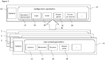
- Figure 1 specifically shows a 'high-cost' sensor in the form of a camera system 13.
- the camera system 13 has a series of configuration parameters 11 which control the operation of the camera system 13.
- Example configuration parameters 11 can be an activation/deactivation parameter 12 which causes the camera to be active or inactive, an angle (or direction) parameter 14 which controls the camera system to be orientated with a specific field of view, a mode of operation parameter 16 which controls the mode of operation of the camera (for example to control the output resolution of the images), a shutter speed parameter 18 configured to control the shutter speed of the camera system, a frames per second parameter 20 configured to control the number of image frames to be captured per second, and so on.
- Each of these configuration parameters can be dynamically configured or controlled based on receipt of trigger control messages 30 or other received trigger control signals.
- the trigger control message or signals are generated directly by a suitable 'low-cost' wearable sensor.
- a suitable 'low-cost' wearable sensor In the example shown in Figure 1 there are shown three earbud ('low-cost') sensors 1, 3, 5 configured to monitor a user context or user context parameter 21 and generate suitable trigger control messages based on the user context parameter 21.
- 'low-cost' sensors 1, 3, 5 configured to monitor a user context or user context parameter 21 and generate suitable trigger control messages based on the user context parameter 21.
- any suitable number of wearable sensors may be employed in a system.
- the user context parameters can be determined by the sensor based on one or more sensed parameters, such as pulse, blood pressure, eye-movement or other body related metrics, audio signals, displacement and/or velocity and/or acceleration sensed from the user by the wearable sensor.
- Examples of user context parameters 21 can be location 22, which determines the location or position of the user within the environment, and movement 24 which characterizes the movement (or activity) of the user.
- the location 22 and movement user context parameters can be determined based on the sensed displacement and/or velocity and/or acceleration.
- Other example context parameters 21 may be emotion 26, and mental status 28 which could for example be obtained based on the body related metrics.
- These user context parameters 21 can then be used to generate the trigger control messages or signals 30.
- the earbud (or suitable wearable/low-cost) sensor is configured to obtain at least one user context parameter as shown in Figure 2 by step 101.
- the system can be configured to obtain or determine any triggers based on the obtained at least one user contact parameter from at least one user as shown in Figure 2 by step 103.
- the camera sensor system having received the trigger message or signal is configured to dynamically configure the camera sensor based on the trigger message as shown in Figure 2 by step 105.
- the obtaining (or generation) of the trigger message occurs within the wearable or personal sensor.
- the obtaining of the trigger message can be performed elsewhere.
- the wearable sensors ('low-cost' sensors) communicate to the camera ('high-cost') sensor and the trigger messages are obtained internally within the camera ('high-cost') sensor and used to configure the camera ('high-cost') sensor.
- management or control system apparatus which is configured to receive the sensor information from the (wearable) sensors and from this sensor information (or at least a filtered or processed form suitable for communication over a wireless communication link) the user context parameters and the trigger messages generated and passed to the (camera) configurable sensor.
- FIG. 3 shows schematically an example system of wearable sensors, camera sensors and a management or control system apparatus (which is physically separate from camera or earbud sensors) and suitable for implementing the dynamic control of the camera sensor according to some embodiments. It is understood that in some embodiments the management or control system apparatus functions can be implemented in either of, or distributed between, the wearable sensors and the camera sensor.
- the management system apparatus 201 can in some embodiments comprise an application broker 219.
- the application broker 219 can be configured to register the rules of the camera operation.
- the rules in some embodiments can comprise 2 parts.
- the first part of the rule is a user context of interest and the second part of the rule is a corresponding camera configuration or parameter configurations.
- the user context of interest can in some embodiments be considered to be a context parameter.
- the user context of interest or context parameter in some embodiments can be specific with respect to a user or a defined group of users (or sensors) or may be generally applicable to all users (or sensors).
- the context parameter may be defined by one of more sensor signals values.
- the camera configuration may affect one or more camera parameters.
- a rule may be to highlight a user "Tom” when they look tired, which triggers the camera to locate the user "Tom” within a field of view by changing the angle configuration parameter.
- the context parameter is the determination of "Tom” looking tired which can be defined in terms of sensor data values representing a lack of motion of "Tom” or head motion sensor values indicating tiredness.
- the parameter configurations furthermore in this example would be changing the angle configuration parameter to bring "Tom" within the field of view.
- a further example could be to lower the frame rate per second when it is determined that nothing is moving within a defined area.
- the management system apparatus 201 can comprise a rule translator 217.
- the rule translator 217 can be configured to separate the rule into suitable user contexts of interest and camera configurations.
- the management system apparatus 201 can comprise a sensor interface 211.
- the sensor interface 211 can be configured to operate as an interface between the management system apparatus and the wearable sensors.
- the sensor interface is known as an earbud broker configured to operate as a broker between the earbud sensor and management system apparatus.
- the sensor interface211 may be configured to receive the user contexts of interest from the rule translator 217 and pass them to the earbud sensors for the earbud sensors to monitor.
- the sensor interface 211 may be configured to receive an indicator that the context of interest has been sensed.
- the management system apparatus 201 can comprise a configuration scheduler 215 configured to receive via the sensor interface 211 any indicators from the earbud sensors that user context of interest have been detected.
- the indications from multiple and potentially all of the earbud sensors may be aggregated and then using the rule translator 217 and/or application broker 219 generate suitable camera configuration controls (the trigger messages).
- the management system apparatus 201 can comprise a configurable sensor interface 213 configured to control the sending of the configuration control results to the camera 13.
- the configurable sensor interface 213 is known as a camera broker configured to operate as a broker between the camera and management system apparatus.
- the configuration control results can then dynamically change the camera configuration.
- the earbud can comprise a sensor broker 231.
- the sensor broker 231 is configured as an interface with the sensor elements and activate suitable sensor modalities, receive the sensor streams and forward the sensed data to a sensing task processor 231.
- the earbud can furthermore comprise a system interface 235.
- the system interface235 (or system broker as it may also be known in some embodiments) can be configured as the interface with the management system apparatus 201 and configured to receive the user contexts of interest to monitor and pass these to the sensing task processor 231.
- the earbud can comprise a sensing task processor 233.
- the sensing task processor 233 is configured to receive the sensor data and the user contexts of interest and monitor whether the sensor data matches any of the user contexts of interest.
- the sensing task processor may implement this in any suitable manner and may comprise sensing modalities, feature extraction and a classifier.
- the sensing task processor 233 determines a context of interest from the sensor data then this may be indicated to the system interface 235 which communicates this to the management system apparatus.
- the functionality of the earbud sensors for example the sensing task processor, for at least some of the sensors may be offloaded to management system apparatus (or the camera where the functionality of the management system apparatus is implemented in the camera).
- the camera can comprise a system interface 207.
- the system interface 207 (or system broker as it may also be known in some embodiments) is configured as an interface with the management system apparatus and can be configured to receive a list of configurations from the management system apparatus.
- the camera 13 can furthermore comprise a camera configurator 209.
- the camera configurator can be configured to dynamically change the camera configuration based on a received message from the system broker 207.
- the camera 13 can furthermore comprise a recording management 210.
- the recording management 210 is configured to manage the recording process.
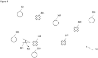
- Figure 4 for example shows a system within a factory, industrial or commercial areas 51 configured to monitor the health and safety of the workers or users within the area 51. This for example may be particularly important in areas where employees or users use potentially lethal machines or substances and a prompt response to any accident is crucial.
- a series of users for example users 'Annie' 301, 'Bob' 303, 'Carl' 305, 'Doug' 307, and 'Eric' 309 within the area and equipped with a wearable sensor.
- a number of cameras 311, 313, 317, 319 can be configured to dynamically operate based on the trigger messages or signals received from the wearable sensors.
- the camera 313 has a first field of view 314 and can view user 'Bob' 303 but not 'Carl' 305.
- a trigger event generated by the wearable sensor on 'Carl' 305 causes the camera 313 to change its field of view shown by arrow 315 such that the camera 313 can now capture an image in which 'Carl' 305 is visible and can be monitored by the camera.
- the system shows a way to unobtrusively monitor the workers and be able to trigger a re-configuration of the cameras in the factory to focus on a specific subject or more than one subject simultaneously.
- the configuration rules can be specified.
- Example rules may be specific as discussed above for a user. For example 'focus on carl when 'Carl' is working with the power hammer and is showing drowsiness'. Some of the rules could be generic. For example 'zoom-in on anyone who looks dizzy'.
- the wearable sensor can in some embodiments be an earbud sensor used to detect the exact user context.
- the earbud can comprise an inertial sensor for motion sensing and microphone for audio sensing. Using this sensor data the earbud can be configured to detect a power hammer by analysing the audio signals (for example through machine learning models).
- the motion sensing can be used to detect drowsiness or dizziness by sensing the motion of a user's head.
- the rules can be created with any combination of the contexts detected by the earbuds and the configurations allowed by the cameras.
- rules can be chained or combined with one another using suitable logical operators (in other words use of operators AND, OR etc).
- the embodiments may contribute in that it can be possible to reduce the number of cameras deployed in a factory floor/area given that the available ones can be dynamically re-purposed to cover different areas. Also there may be improvements in that there are potential savings in network bandwidth and power consumption since the cameras can stay in an idle mode, without streaming any data, until an event is detected by the earbuds.
- FIG. 5 there is shown in a second example of a practical implementation within which the apparatus shown in Figures 1 and 3 may be implemented.
- the example shows the interior of an autonomous vehicle 401.
- the autonomous vehicle 401 comprises a camera 470 configured to monitor the interior of the vehicle.
- the camera 470 is wirelessly coupled via a management system 460.
- the autonomous vehicle 401 furthermore comprises the management system 460 which is configured to control the camera 470 and may also control the autonomous vehicle 401.
- the autonomous vehicle 401 can be located passengers or users.
- each of the users are equipped with a wearable or personal sensors (for example a earbud) which is wirelessly coupled to the management system 460 (for example links 443 and 453).
- the management system 460 for example links 443 and 453.
- a first user 410 with a first sensor 412 a second user 420 with a second sensor 422, a third user 430 with a third sensor 432, a fourth user 440 with a fourth sensor 442 and a fifth user 450 with a fifth sensor 452.
- the camera 470 can be dynamically configured with a field of view to monitor the users. These images may then be used by the management system 460 to determine whether or not any of the users are experiencing stress and control the vehicle accordingly.
- the camera 470 may initially be focusing with a first field of view 471 to view the fourth user 440.
- the fifth user 450 with the fifth sensor 452 could be experiencing signs of anxiety which are detected by the sensor 452 (for example an elevated heart rate causing a user context parameter of interest to be detected), which is communicated via link 453 to the management system 460 which identifies the camera configuration required based on the stored rules to enable a reconfiguration of the camera to have a field of view 471 to view the fifth user as shown by the field of view 473.
- the camera can then be used to analyse the image containing the fifth user and determine whether or not the image contains any signs of anxiety of the user and change the driving profile of the autonomous vehicle accordingly.
- the facial expressions of the users within the vehicle can provide feedback to the vehicle AI system for self-adaptation.
- the vehicle can give explanations about its decision-making process. Alternately, it can play soothing music to calm the user or perform another user-calming function.
- facial expression detection can also be used to personalize the in-vehicle user experience (e.g., to select a music playlist based on a user's current emotion).
- the earbud or wearable sensor worn by the users can be configured to detect coarse-level facial expressions, either using inertial sensors based on the movement of the head or jaw, or using the microphone. Once a coarse-grained expression is detected by the earbud of a specific user, this trigger triggers a reconfiguration of the vehicle camera, in other words the camera can be rotated, zoomed, and or focussed to place an emphasis or concentrate on that specific user so that a fine-grained facial expression detection operation can be performed.
- inertial sensors are much cheaper than a camera from an energy-perspective, they are able to continuously analyse and detect 'coarse-grained' facial expressions or anxiety levels of all the passengers in the vehicle. As a result, the energy and bandwidth hungry camera is used sparingly.
- the working environment 501 comprises a smart factory production line 540 with a series of machines 510, 520, 530 and their operators 'Fred' 550, and 'Greg' 560.
- the operators can equipped with suitable wearable or personal sensors 551 (associated with 'Fred' 550) and sensor 561 (associated with 'Greg' 560).
- the camera sensors may be dynamically configurable.
- management system apparatus 580 in communication with the wearable sensors and the camera.
- the example shown in Figure 6 shows a machine 520 about to malfunction (for example generating an abnormal noise 521).
- the noise as a user context of interest can be detected by one or more of the wearable sensors 551, 561.
- an industrial machine When an industrial machine is operating it emits specific sounds which are different from the sounds emitted when the operation is not nominal or is about to fail.
- an event could be determined when the machine is not producing the nominal sounds. This event can be indicated to the management system 580 and cause a reconfiguration of the camera 570 to view the machine 520 as shown by the dashed line 571 when needed.
- the images captured by the camera 570 can then be used to determine the potential fault with the machine and therefore may additionally cause a suitable industrial control message to be generated stopping the process, diverting the process to a working machine or alerting users to the potential fault.
- the microphone on the earbud sensor could be used to infer the status of machines around a user, and cause the cameras to aim in that direction to have a better understanding of what is happening. For example, if a machine malfunction is detected through its audio signature, the system can be configured to focus multiple cameras on this machine, so that a human observer can have a detailed look to determine the potential or actual problem.
- the contexts detectable by the earbuds can include also circumstances related to processes happening around the user wearing the earbuds even if where the user is not directly involved (in other words being able to detect faults or potential faults in machines other than the one the user is operating or overseeing).
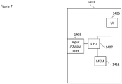
- the device may be any suitable electronics device or apparatus.
- the device 1400 comprises at least one processor or central processing unit 1407.
- the processor 1407 can be configured to execute various program codes such as the methods such as described herein.
- the device 1400 comprises a memory 1411.
- the at least one processor 1407 is coupled to the memory 1411.
- the memory 1411 can be any suitable storage means.
- the memory 1411 comprises a program code section for storing program codes implementable upon the processor 1407.
- the memory 1411 can further comprise a stored data section for storing data, for example data that has been processed or to be processed in accordance with the embodiments as described herein. The implemented program code stored within the program code section and the data stored within the stored data section can be retrieved by the processor 1407 whenever needed via the memory-processor coupling.
- the device 1400 comprises a user interface 1405.
- the user interface 1405 can be coupled in some embodiments to the processor 1407.
- the processor 1407 can control the operation of the user interface 1405 and receive inputs from the user interface 1405.
- the user interface 1405 can enable a user to input commands to the device 1400, for example via a keypad/touch interface.
- the user interface 1405 can enable the user to obtain information from the device 1400.
- the user interface 1405 may comprise a display configured to display information from the device 1400 to the user.
- the user interface 1405 can in some embodiments comprise a touch screen or touch interface capable of both enabling information to be entered to the device 1400 and further displaying information to the user of the device 1400.
- the device 1400 comprises an input/output port 1409.
- the input/output port 1409 in some embodiments comprises a transceiver.
- the transceiver in such embodiments can be coupled to the processor 1407 and configured to enable a communication with other apparatus or electronic devices, for example via a wireless communications network.
- the transceiver or any suitable transceiver or transmitter and/or receiver means can in some embodiments be configured to communicate with other electronic devices or apparatus via a wire or wired coupling.
- the transceiver can communicate with further apparatus by any suitable known communications protocol.
- the transceiver can use a suitable universal mobile telecommunications system (UMTS) protocol, a wireless local area network (WLAN) protocol such as for example IEEE 802.X, a suitable short-range radio frequency communication protocol such as Bluetooth, or infrared data communication pathway (IRDA).
- UMTS universal mobile telecommunications system
- WLAN wireless local area network
- IRDA infrared data communication pathway
- the transceiver input/output port 1409 may be configured to receive the signals and in some embodiments determine the parameters as described herein by using the processor 1407 executing suitable code.
- apparatus and mechanisms as discussed above may have the advantage in being able to use a first set of sensors (which may be 'low-cost') in dynamically adapting the operating parameters of configurable sensors (which may be 'high-cost') operating within industrial systems. For example causing dynamic adaptation within a camera-based industrial systems in order to save resources such as network bandwidth and energy consumption. Additionally some embodiments can be employed to increase coverage or effectiveness of the system, for example extending scene coverage, and/or improve the data captured by the system.
- Some embodiments may have advantages over sensor systems in that they do not require the deployment of large numbers of configurable sensors, such as image camera-based systems, and are therefore cheaper and more efficient to implement and reduce the amount of resources required to operate the system.
- some embodiments are able to flexibly and dynamically configure the system (such as for a camera: field of view, focus, zoom, resolution). This has a direct improvement on the accuracy and range of data provided by the configurable sensor and therefore may improve the effectiveness of any control system based on the output of the configurable sensor. For example in video processing applications where the camera is within a self-driving car with multiple passengers, the camera can be configured to decide on which passenger to focus on as it may not be possible to focus on all of the passengers at the same time.
- the various embodiments of the invention may be implemented in hardware or special purpose circuits, software, logic or any combination thereof.
- some aspects may be implemented in hardware, while other aspects may be implemented in firmware or software which may be executed by a controller, microprocessor or other computing device, although the invention is not limited thereto.
- firmware or software which may be executed by a controller, microprocessor or other computing device, although the invention is not limited thereto.
- While various aspects of the invention may be illustrated and described as block diagrams, flow charts, or using some other pictorial representation, it is well understood that these blocks, apparatus, systems, techniques or methods described herein may be implemented in, as non-limiting examples, hardware, software, firmware, special purpose circuits or logic, general purpose hardware or controller or other computing devices, or some combination thereof.
- the embodiments of this invention may be implemented by computer software executable by a data processor of the mobile device, such as in the processor entity, or by hardware, or by a combination of software and hardware.
- any blocks of the logic flow as in the Figures may represent program steps, or interconnected logic circuits, blocks and functions, or a combination of program steps and logic circuits, blocks and functions.
- the software may be stored on such physical media as memory chips, or memory blocks implemented within the processor, magnetic media such as hard disk or floppy disks, and optical media such as for example DVD and the data variants thereof, CD.
- the memory may be of any type suitable to the local technical environment and may be implemented using any suitable data storage technology, such as semiconductor-based memory devices, magnetic memory devices and systems, optical memory devices and systems, fixed memory and removable memory.
- the data processors may be of any type suitable to the local technical environment, and may include one or more of general purpose computers, special purpose computers, microprocessors, digital signal processors (DSPs), application specific integrated circuits (ASIC), gate level circuits and processors based on multi-core processor architecture, as non-limiting examples.
- Embodiments of the inventions may be practiced in various components such as integrated circuit modules.
- the design of integrated circuits is by and large a highly automated process.
- Complex and powerful software tools are available for converting a logic level design into a semiconductor circuit design ready to be etched and formed on a semiconductor substrate.
- Programs such as those provided by Synopsys, Inc. of Mountain View, California and Cadence Design, of San Jose, California automatically route conductors and locate components on a semiconductor chip using well established rules of design as well as libraries of pre-stored design modules.
- the resultant design in a standardized electronic format (e.g., Opus, GDSII, or the like) may be transmitted to a semiconductor fabrication facility or "fab" for fabrication.
Landscapes
- Engineering & Computer Science (AREA)
- Multimedia (AREA)
- Signal Processing (AREA)
- Physics & Mathematics (AREA)
- Health & Medical Sciences (AREA)
- Life Sciences & Earth Sciences (AREA)
- General Physics & Mathematics (AREA)
- Pathology (AREA)
- Biophysics (AREA)
- Biomedical Technology (AREA)
- Heart & Thoracic Surgery (AREA)
- Medical Informatics (AREA)
- Molecular Biology (AREA)
- Surgery (AREA)
- Animal Behavior & Ethology (AREA)
- General Health & Medical Sciences (AREA)
- Public Health (AREA)
- Veterinary Medicine (AREA)
- User Interface Of Digital Computer (AREA)
Abstract
Description
- The present application relates to apparatus and methods for sensor configuration based on other sensor context determination, for example, but not exclusively for camera sensor configuration based on wearable sensor context determination.
- Image and video processing technology is a key driver for a number of high-value applications in areas such as industrial automation, self-driving automobiles and public safety systems. To enable these applications, it is common to deploy one or multiple 'high-cost' sensors. By 'high-cost' the disclosure means sensors which require significant power and/or communication bandwidth and/or processing cost to operate. An example of such 'high-cost' sensors is an image camera which may be configured to continuously record and analyse video streams of a scene to extract meaningful information. For instance, a camera mounted inside a self-driving car can be used to analyse the facial expressions of its passengers determine whether the passengers are experiencing anxiety or stress. This information can then be used to control the car's self-driving (Al) system in order to attempt to reduce the stress or anxiety of the passenger, for example to control the car speed to slow the car. In a smart factory, image cameras can monitor the factory floor to look for anomalous events and provide feedback to a human operator or safety system. 'High-cost' sensors may furthermore include sensors which have a limited designed usage lifespan or consume resources which may or may not be able to be replaced when in use. For example a 'high-cost' sensor may be a chemical sensor which uses a chemical reagent to enable detection.
- There is provided according to a first aspect an apparatus comprising means for:
obtaining sensor data from at least one first, wearable, sensor, the sensor data comprising at least one sensor signal; comparing the sensor data to a context parameter; and causing at least one second sensor to be dynamically configured based on the comparison. - The sensor data may comprise at least one of: at least one audio signal from at least one microphone; at least one image from at least one camera; at least one of displacement, velocity, acceleration from an inertial measurement sensor; and at least one biometric value from a biometric sensor.
- The means for comparing the sensor data to a context parameter may be further for at least one of: sensing modalities of the sensor data; feature extraction of the sensor data; and applying a classifier function to the sensor data.
- The means for may be further for obtaining the at least one context parameter, the context parameter may be defined by one or more values of the at least one sensor signal.
- The means for causing the at least one second sensor to be dynamically configured based on the comparison may be for generating a signal for causing the at least one second sensor to be dynamically configured based on the comparison of the one or more values of the at least one sensor signal to the at least one sensor signal from the at least one first sensor.
- The means for may be for controlling the at least one first sensor to provide the at least one signal based on the at least one context parameter.
- The apparatus may comprise one of: the at least one wearable sensor; the at least one second sensor; a personal sensor; a controller for the at least one second sensor; and an earbud sensor.
- The at least one second sensor may be a camera.
- The means for causing the at least one second sensor to be dynamically configured based on the comparison may be for at least one of: causing an activation/deactivation of the camera; causing a change in an angle of direction of the camera; causing a change in a field of view/zoom of the camera; causing a change in a mode of operation of the camera; causing a change in a shutter speed of the camera; and causing a change in a frame rate of the camera.
- According to a second aspect there is provided an apparatus comprising means for: obtaining sensor data from at least one first sensor, the sensor data comprising at least one sensor signal; comparing the sensor data to a context parameter; and causing at least one second sensor to be dynamically configured based on the comparison.
- According to a third aspect there is provided a method comprising: obtaining sensor data from at least one first, wearable, sensor, the sensor data comprising at least one sensor signal; comparing the sensor data to a context parameter; and causing at least one second sensor to be dynamically configured based on the comparison.
- The sensor data may comprise at least one of: at least one audio signal from at least one microphone; at least one image from at least one camera; at least one of displacement, velocity, acceleration from an inertial measurement sensor; and at least one biometric value from a biometric sensor.
- Comparing the sensor data to a context parameter may comprise at least one of: sensing modalities of the sensor data; feature extraction of the sensor data; and applying a classifier function to the sensor data.
- The method may further comprise obtaining the at least one context parameter, the context parameter may be defined by one or more values of the at least one sensor signal.
- Causing the at least one second sensor to be dynamically configured based on the comparison may further comprise generating a signal for causing the at least one second sensor to be dynamically configured based on the comparison of the one or more values of the at least one sensor signal to the at least one sensor signal from the at least one first sensor.
- The method may comprise controlling the at least one first sensor to provide the at least one signal based on the at least one context parameter.
- The at least one second sensor may be a camera.
- Causing the at least one second sensor to be dynamically configured based on the comparison may comprise at least one of: causing an activation/deactivation of the camera; causing a change in an angle of direction of the camera; causing a change in a field of view/zoom of the camera; causing a change in a mode of operation of the camera; causing a change in a shutter speed of the camera; and causing a change in a frame rate of the camera.
- According to a fourth aspect there is provided a method comprising: obtaining sensor data from at least one first sensor, the sensor data comprising at least one sensor signal; comparing the sensor data to a context parameter; and causing at least one second sensor to be dynamically configured based on the comparison.
- According to a fifth aspect there is provided an apparatus comprising at least one processor and at least one memory including a computer program code, the at least one memory and the computer program code configured to, with the at least one processor, cause the apparatus at least to: obtain sensor data from at least one first, wearable, sensor, the sensor data comprising at least one sensor signal; compare the sensor data to a context parameter; and cause at least one second sensor to be dynamically configured based on the comparison.
- The sensor data may comprise at least one of: at least one audio signal from at least one microphone; at least one image from at least one camera; at least one of displacement, velocity, acceleration from an inertial measurement sensor; and at least one biometric value from a biometric sensor.
- Comparing the sensor data to a context parameter may further cause the apparatus to perform at least one of: sense modalities of the sensor data; feature extract of the sensor data; and apply a classifier function to the sensor data.
- The apparatus may be further caused to obtain the at least one context parameter, the context parameter may be defined by one or more values of the at least one sensor signal.
- Causing the at least one second sensor to be dynamically configured based on the comparison may further cause the apparatus to generate a signal for causing the at least one second sensor to be dynamically configured based on the comparison of the one or more values of the at least one sensor signal to the at least one sensor signal from the at least one first sensor.
- The apparatus may further be caused to control the at least one first sensor to provide the at least one signal based on the at least one context parameter.
- The apparatus may comprise one of: the at least one wearable sensor; the at least one second sensor; a personal sensor; a controller for the at least one second sensor; and an earbud sensor.
- The at least one second sensor may be a camera.
- Causing the at least one second sensor to be dynamically configured based on the comparison may cause the apparatus to perform at least one of: cause an activation/deactivation of the camera; cause a change in an angle of direction of the camera; cause a change in a field of view/zoom of the camera; cause a change in a mode of operation of the camera; cause a change in a shutter speed of the camera; and cause a change in a frame rate of the camera.
- According to a sixth aspect there is provided an apparatus comprising at least one processor and at least one memory including a computer program code, the at least one memory and the computer program code configured to, with the at least one processor, cause the apparatus at least to: obtain sensor data from at least one first sensor, the sensor data comprising at least one sensor signal; compare the sensor data to a context parameter; and cause at least one second sensor to be dynamically configured based on the comparison.
- According to a seventh aspect there is provided an apparatus comprising obtaining circuitry configured to obtain sensor data from at least one first, wearable, sensor, the sensor data comprising at least one sensor signal; comparing circuitry configured to compare the sensor data to a context parameter; and controlling circuitry configured to cause at least one second sensor to be dynamically configured based on the comparison.
- According to an eighth aspect there is provided a computer program comprising instructions [or a computer readable medium comprising program instructions] for causing an apparatus to perform at least the following: obtaining sensor data from at least one first, wearable, sensor, the sensor data comprising at least one sensor signal; comparing the sensor data to a context parameter; and causing at least one second sensor to be dynamically configured based on the comparison.
- According to a ninth aspect there is provided a non-transitory computer readable medium comprising program instructions for causing an apparatus to perform at least the following: obtaining sensor data from at least one first, wearable, sensor, the sensor data comprising at least one sensor signal; comparing the sensor data to a context parameter; and causing at least one second sensor to be dynamically configured based on the comparison.
- According to a tenth aspect there is provided an apparatus comprising: means for obtaining sensor data from at least one first, wearable, sensor, the sensor data comprising at least one sensor signal; means for comparing the sensor data to a context parameter; and means for causing at least one second sensor to be dynamically configured based on the comparison.
- According to an eleventh aspect there is provided a computer readable medium comprising program instructions for causing an apparatus to perform at least the following: obtaining sensor data from at least one first, wearable, sensor, the sensor data comprising at least one sensor signal; comparing the sensor data to a context parameter; and causing at least one second sensor to be dynamically configured based on the comparison.
- An apparatus comprising means for performing the actions of the method as described above.
- An apparatus configured to perform the actions of the method as described above.
- A computer program comprising program instructions for causing a computer to perform the method as described above.
- A computer program product stored on a medium may cause an apparatus to perform the method as described herein.
- An electronic device may comprise apparatus as described herein.
- A chipset may comprise apparatus as described herein.
- Embodiments of the present application aim to address problems associated with the state of the art.
- For a better understanding of the present application, reference will now be made by way of example to the accompanying drawings in which:
-
Figure 1 shows schematically a system of apparatus suitable for implementing some embodiments; -
Figure 2 shows a flow diagram of the operation of the system as shown inFigure 1 in some embodiments; -
Figure 3 shows schematically a further system of apparatus suitable for implementing some embodiments; -
Figure 4 shows schematically a first example system suitable for implementing some embodiments; -
Figure 5 shows schematically a second example system of apparatus suitable for implementing some embodiments; -
Figure 6 shows schematically a third example system of apparatus suitable for implementing some embodiments; and -
Figure 7 shows an example device suitable for implementing the apparatus shown in the figures above. - The following describes in further detail a suitable system of apparatus and possible mechanisms for the provision of efficient sensor configuration.
- The concept may be exemplified by the use of a set (or type) of sensors. This set of sensors may be configurable sensors and may be 'high-cost' sensors. The system may furthermore feature a further set (or type) of sensors. This further set of sensors may be sensors which provide data which is used to control the 'high-cost' set of sensors. The further set (or type) of sensors may be 'low-cost' sensors. A 'low-cost' sensor may be one which has a lower resource consumption or requirement than the 'high-cost' sensor in terms of at least one resource. As such the terms 'low-cost' and 'high-cost' are relative terms. For example a 'low-cost' sensor may still have an enormous cost so long as it is still lower than the 'high-cost' sensor such that its use will still result in an overall lower use of whatever resource we are assessing for a 'cost' parametric. Thus in the example of a limited lifespan sensor a 'low-cost' sensor may be one which has a fixed and non-replaceable power source but has a designed lifespan which is longer than a 'high-cost' sensor.
- In some embodiments there can be no difference in price/processing/power consumption between the sets of sensors.
- In some embodiments data from the sensor or sensors may be employed to reconfigure the reconfigurable sensor(s). This may be even where the (wearable) sensors from the further set have a greater associated cost factor or where there is no cost factor involved.
- In some embodiments the examples allow the system to get the best data out of the reconfigurable sensor.
- Examples of 'low-cost' sensors or wearable sensors may be ear-worn devices such as earbuds. The sensors may be employed to dynamically 'sense' an environment and in some embodiments the users within the environment and their operating conditions, and use this information to adapt the operating parameters of the configurable or 'high-cost' (for example camera) sensor system..
- In the following examples the configurable or 'high-cost' sensor is a camera system, for example a camera mounted on at least one adjustable gimbal.
- Furthermore in the following examples the 'low-cost' sensor is a wearable or personal sensor. The personal sensor may be an example of a sensor configured to monitor a user within their environment. The sensor may be located on or about a user. For example the sensor may be in direct contact with the user, for example a smart earbud located in the ear of the user. Furthermore in some embodiments the sensor may be affixed to clothing of the user, for example a sensor button worn on a shirt or jumper, or may be attached to a lanyard and worn. In some embodiments the sensor is one which is associated with the user and monitoring the user in their environment without necessarily being located on or worn by the user. For example a non-worn personal sensor may be a mini-drone comprising camera and microphones monitoring the user. The sensor may be configured to act as an external sensor which can anticipate the dynamic context of the environment (e.g., number of people, their current activities) and provide this feedback to the camera system which leads to a real-time reconfiguration of the camera parameters (e.g., field of view, zoom).
- Furthermore in some embodiments the further set of sensors may be an assorted or diverse range of sensors. For example the further set of sensors can comprise a number of wearable (smart earbud) sensors which are augmented with other sensors including inertial measurement unit (IMU) sensors, audio sensors, and RF sensors.
- In such a manner the example wearable sensors may be able to capture an individual's context of interest and furthermore enable a more energy-efficient system to be implemented when compared to continuous camera recording and processing.
- Additionally the embodiments as described hereafter can be employed to provide a more effective detection environment and thus not limited to camera-visible content. In other words users may be monitored out of the camera's view but in locations which the camera may be configured to view, for example by repositioning the camera of changing a level of zoom.
- With respect to
Figure 1 is shown a schematic view of example apparatus implementing some embodiments.Figure 1 specifically shows a 'high-cost' sensor in the form of acamera system 13. Thecamera system 13 has a series ofconfiguration parameters 11 which control the operation of thecamera system 13.Example configuration parameters 11 can be an activation/deactivation parameter 12 which causes the camera to be active or inactive, an angle (or direction)parameter 14 which controls the camera system to be orientated with a specific field of view, a mode ofoperation parameter 16 which controls the mode of operation of the camera (for example to control the output resolution of the images), ashutter speed parameter 18 configured to control the shutter speed of the camera system, a frames persecond parameter 20 configured to control the number of image frames to be captured per second, and so on. Each of these configuration parameters can be dynamically configured or controlled based on receipt oftrigger control messages 30 or other received trigger control signals. - In the example shown in
Figure 1 the trigger control message or signals are generated directly by a suitable 'low-cost' wearable sensor. In the example shown inFigure 1 there are shown three earbud ('low-cost')sensors user context parameter 21 and generate suitable trigger control messages based on theuser context parameter 21. However any suitable number of wearable sensors may be employed in a system. - The user context parameters can be determined by the sensor based on one or more sensed parameters, such as pulse, blood pressure, eye-movement or other body related metrics, audio signals, displacement and/or velocity and/or acceleration sensed from the user by the wearable sensor. Examples of
user context parameters 21 can belocation 22, which determines the location or position of the user within the environment, andmovement 24 which characterizes the movement (or activity) of the user. Thelocation 22 and movement user context parameters can be determined based on the sensed displacement and/or velocity and/or acceleration. Otherexample context parameters 21 may beemotion 26, andmental status 28 which could for example be obtained based on the body related metrics. - These
user context parameters 21 can then be used to generate the trigger control messages or signals 30. - This is shown for example with respect to
Figure 2 where a flow diagram shows the operations of the system shown inFigure 1 . - Thus for example the earbud (or suitable wearable/low-cost) sensor is configured to obtain at least one user context parameter as shown in
Figure 2 bystep 101. - Having determined at least one user context parameter then the system can be configured to obtain or determine any triggers based on the obtained at least one user contact parameter from at least one user as shown in
Figure 2 bystep 103. - Then the camera sensor system, having received the trigger message or signal is configured to dynamically configure the camera sensor based on the trigger message as shown in
Figure 2 bystep 105. - In this example the obtaining (or generation) of the trigger message occurs within the wearable or personal sensor. However, in some embodiments, the obtaining of the trigger message can be performed elsewhere. For example in some embodiments the wearable sensors ('low-cost' sensors) communicate to the camera ('high-cost') sensor and the trigger messages are obtained internally within the camera ('high-cost') sensor and used to configure the camera ('high-cost') sensor.
- Furthermore in some embodiments there may be management or control system apparatus which is configured to receive the sensor information from the (wearable) sensors and from this sensor information (or at least a filtered or processed form suitable for communication over a wireless communication link) the user context parameters and the trigger messages generated and passed to the (camera) configurable sensor.
- For example
Figure 3 shows schematically an example system of wearable sensors, camera sensors and a management or control system apparatus (which is physically separate from camera or earbud sensors) and suitable for implementing the dynamic control of the camera sensor according to some embodiments. It is understood that in some embodiments the management or control system apparatus functions can be implemented in either of, or distributed between, the wearable sensors and the camera sensor. - The
management system apparatus 201 can in some embodiments comprise anapplication broker 219. Theapplication broker 219 can be configured to register the rules of the camera operation. The rules in some embodiments can comprise 2 parts. - The first part of the rule is a user context of interest and the second part of the rule is a corresponding camera configuration or parameter configurations. The user context of interest can in some embodiments be considered to be a context parameter. The user context of interest or context parameter in some embodiments can be specific with respect to a user or a defined group of users (or sensors) or may be generally applicable to all users (or sensors). The context parameter may be defined by one of more sensor signals values. Furthermore the camera configuration may affect one or more camera parameters.
- For example a rule may be to highlight a user "Tom" when they look tired, which triggers the camera to locate the user "Tom" within a field of view by changing the angle configuration parameter. In this example the context parameter is the determination of "Tom" looking tired which can be defined in terms of sensor data values representing a lack of motion of "Tom" or head motion sensor values indicating tiredness. The parameter configurations furthermore in this example would be changing the angle configuration parameter to bring "Tom" within the field of view. A further example could be to lower the frame rate per second when it is determined that nothing is moving within a defined area.
- In some embodiments the
management system apparatus 201 can comprise arule translator 217. Therule translator 217 can be configured to separate the rule into suitable user contexts of interest and camera configurations. - In some embodiments the
management system apparatus 201 can comprise asensor interface 211. Thesensor interface 211 can be configured to operate as an interface between the management system apparatus and the wearable sensors. In some examples the sensor interface is known as an earbud broker configured to operate as a broker between the earbud sensor and management system apparatus. For example where the user contexts are obtained within the wearable sensors the sensor interface211 may be configured to receive the user contexts of interest from therule translator 217 and pass them to the earbud sensors for the earbud sensors to monitor. Furthermore at runtime when the event or user context of interest is detected by the earbud then thesensor interface 211 may be configured to receive an indicator that the context of interest has been sensed. - In some embodiments the
management system apparatus 201 can comprise aconfiguration scheduler 215 configured to receive via thesensor interface 211 any indicators from the earbud sensors that user context of interest have been detected. The indications from multiple and potentially all of the earbud sensors may be aggregated and then using therule translator 217 and/orapplication broker 219 generate suitable camera configuration controls (the trigger messages). - The
management system apparatus 201 can comprise aconfigurable sensor interface 213 configured to control the sending of the configuration control results to thecamera 13. In some examples theconfigurable sensor interface 213 is known as a camera broker configured to operate as a broker between the camera and management system apparatus. The configuration control results can then dynamically change the camera configuration. - With respect to the earbud or
wearable sensor 1, the earbud can comprise asensor broker 231. Thesensor broker 231 is configured as an interface with the sensor elements and activate suitable sensor modalities, receive the sensor streams and forward the sensed data to asensing task processor 231. - The earbud can furthermore comprise a
system interface 235. The system interface235 (or system broker as it may also be known in some embodiments) can be configured as the interface with themanagement system apparatus 201 and configured to receive the user contexts of interest to monitor and pass these to thesensing task processor 231. - Additionally the earbud can comprise a
sensing task processor 233. Thesensing task processor 233 is configured to receive the sensor data and the user contexts of interest and monitor whether the sensor data matches any of the user contexts of interest. The sensing task processor may implement this in any suitable manner and may comprise sensing modalities, feature extraction and a classifier. - Furthermore when the
sensing task processor 233 determines a context of interest from the sensor data then this may be indicated to thesystem interface 235 which communicates this to the management system apparatus. In some embodiments the functionality of the earbud sensors, for example the sensing task processor, for at least some of the sensors may be offloaded to management system apparatus (or the camera where the functionality of the management system apparatus is implemented in the camera). - With respect to the
camera 13 the camera can comprise asystem interface 207. The system interface 207 (or system broker as it may also be known in some embodiments) is configured as an interface with the management system apparatus and can be configured to receive a list of configurations from the management system apparatus. - The
camera 13 can furthermore comprise acamera configurator 209. The camera configurator can be configured to dynamically change the camera configuration based on a received message from thesystem broker 207. - Additionally the
camera 13 can furthermore comprise arecording management 210. Therecording management 210 is configured to manage the recording process. - With respect to
Figures 4 to 6 is shown a series of practical implementation examples of the apparatus as shown inFigures 1 and3 . -
Figure 4 for example shows a system within a factory, industrial orcommercial areas 51 configured to monitor the health and safety of the workers or users within thearea 51. This for example may be particularly important in areas where employees or users use potentially lethal machines or substances and a prompt response to any accident is crucial. - In this example are shown a series of users for example users 'Annie' 301, 'Bob' 303, 'Carl' 305, 'Doug' 307, and 'Eric' 309 within the area and equipped with a wearable sensor. Additionally within the
area 51 there are located a number ofcameras Figure 4 thecamera 313 has a first field ofview 314 and can view user 'Bob' 303 but not 'Carl' 305. However a trigger event generated by the wearable sensor on 'Carl' 305 causes thecamera 313 to change its field of view shown byarrow 315 such that thecamera 313 can now capture an image in which 'Carl' 305 is visible and can be monitored by the camera. - In such a manner the system shows a way to unobtrusively monitor the workers and be able to trigger a re-configuration of the cameras in the factory to focus on a specific subject or more than one subject simultaneously. In this context, firstly in the
application broker 319 the configuration rules can be specified. Example rules may be specific as discussed above for a user. For example 'focus on carl when 'Carl' is working with the power hammer and is showing drowsiness'. Some of the rules could be generic. For example 'zoom-in on anyone who looks dizzy'. - The wearable sensor can in some embodiments be an earbud sensor used to detect the exact user context. For example the earbud can comprise an inertial sensor for motion sensing and microphone for audio sensing. Using this sensor data the earbud can be configured to detect a power hammer by analysing the audio signals (for example through machine learning models). Furthermore the motion sensing can be used to detect drowsiness or dizziness by sensing the motion of a user's head.
- The rules can be created with any combination of the contexts detected by the earbuds and the configurations allowed by the cameras.
- In some embodiments rules can be chained or combined with one another using suitable logical operators (in other words use of operators AND, OR etc).
- Furthermore the location of the user, necessary to move the cameras in the appropriate direction, could be obtained by triangulating the radio beacons emitted by the earbud using static receivers in the area.
- In such a manner the embodiments may contribute in that it can be possible to reduce the number of cameras deployed in a factory floor/area given that the available ones can be dynamically re-purposed to cover different areas. Also there may be improvements in that there are potential savings in network bandwidth and power consumption since the cameras can stay in an idle mode, without streaming any data, until an event is detected by the earbuds.
- With respect to
Figure 5 there is shown in a second example of a practical implementation within which the apparatus shown inFigures 1 and3 may be implemented. The example shows the interior of anautonomous vehicle 401. Theautonomous vehicle 401 comprises acamera 470 configured to monitor the interior of the vehicle. Thecamera 470 is wirelessly coupled via amanagement system 460. - The
autonomous vehicle 401 furthermore comprises themanagement system 460 which is configured to control thecamera 470 and may also control theautonomous vehicle 401. - Within the
autonomous vehicle 401 can be located passengers or users. In the example shown inFigure 5 there are five users and where each of the users are equipped with a wearable or personal sensors (for example a earbud) which is wirelessly coupled to the management system 460 (forexample links 443 and 453). Thus for example there may be afirst user 410 with afirst sensor 412, asecond user 420 with asecond sensor 422, athird user 430 with athird sensor 432, afourth user 440 with afourth sensor 442 and afifth user 450 with afifth sensor 452. - The
camera 470 can be dynamically configured with a field of view to monitor the users. These images may then be used by themanagement system 460 to determine whether or not any of the users are experiencing stress and control the vehicle accordingly. - Thus for example as shown in
Figure 5 thecamera 470 may initially be focusing with a first field ofview 471 to view thefourth user 440. However thefifth user 450 with thefifth sensor 452 could be experiencing signs of anxiety which are detected by the sensor 452 (for example an elevated heart rate causing a user context parameter of interest to be detected), which is communicated vialink 453 to themanagement system 460 which identifies the camera configuration required based on the stored rules to enable a reconfiguration of the camera to have a field ofview 471 to view the fifth user as shown by the field ofview 473. The camera can then be used to analyse the image containing the fifth user and determine whether or not the image contains any signs of anxiety of the user and change the driving profile of the autonomous vehicle accordingly. In such a manner the facial expressions of the users within the vehicle can provide feedback to the vehicle AI system for self-adaptation., for e.g., if a passenger is looking anxious about the vehicle's Al-assisted driving, the vehicle can give explanations about its decision-making process. Alternately, it can play soothing music to calm the user or perform another user-calming function. - In addition to the above examples of providing critical real-time feedback, facial expression detection can also be used to personalize the in-vehicle user experience (e.g., to select a music playlist based on a user's current emotion).
- In some embodiments the earbud or wearable sensor worn by the users can be configured to detect coarse-level facial expressions, either using inertial sensors based on the movement of the head or jaw, or using the microphone. Once a coarse-grained expression is detected by the earbud of a specific user, this trigger triggers a reconfiguration of the vehicle camera, in other words the camera can be rotated, zoomed, and or focussed to place an emphasis or concentrate on that specific user so that a fine-grained facial expression detection operation can be performed.
- A benefit of this approach is that as inertial sensors are much cheaper than a camera from an energy-perspective, they are able to continuously analyse and detect 'coarse-grained' facial expressions or anxiety levels of all the passengers in the vehicle. As a result, the energy and bandwidth hungry camera is used sparingly.
- With respect to
Figure 6 a third example is shown whereby the workingenvironment 501 comprises a smartfactory production line 540 with a series ofmachines - Within the environment there furthermore may be located one or more camera sensors such as shown by the
camera sensors - Furthermore there may be a
management system apparatus 580 in communication with the wearable sensors and the camera. - The example shown in
Figure 6 shows amachine 520 about to malfunction (for example generating an abnormal noise 521). The noise as a user context of interest can be detected by one or more of thewearable sensors management system 580 and cause a reconfiguration of thecamera 570 to view themachine 520 as shown by the dashedline 571 when needed. The images captured by thecamera 570 can then be used to determine the potential fault with the machine and therefore may additionally cause a suitable industrial control message to be generated stopping the process, diverting the process to a working machine or alerting users to the potential fault. - In such a manner the microphone on the earbud sensor could be used to infer the status of machines around a user, and cause the cameras to aim in that direction to have a better understanding of what is happening. For example, if a machine malfunction is detected through its audio signature, the system can be configured to focus multiple cameras on this machine, so that a human observer can have a detailed look to determine the potential or actual problem.
- In some embodiments the contexts detectable by the earbuds can include also circumstances related to processes happening around the user wearing the earbuds even if where the user is not directly involved (in other words being able to detect faults or potential faults in machines other than the one the user is operating or overseeing).
- As such these embodiments allow the monitoring of subtle machine operations which could be very difficult to be monitored by humans, in a non-invasive way in simply leveraging the sound emitted from the machine.
- With respect to
Figure 7 an example electronic device which may be used as one of the sensors or management system apparatus is shown. The device may be any suitable electronics device or apparatus. - In some embodiments the
device 1400 comprises at least one processor orcentral processing unit 1407. Theprocessor 1407 can be configured to execute various program codes such as the methods such as described herein. - In some embodiments the
device 1400 comprises amemory 1411. In some embodiments the at least oneprocessor 1407 is coupled to thememory 1411. Thememory 1411 can be any suitable storage means. In some embodiments thememory 1411 comprises a program code section for storing program codes implementable upon theprocessor 1407. Furthermore in some embodiments thememory 1411 can further comprise a stored data section for storing data, for example data that has been processed or to be processed in accordance with the embodiments as described herein. The implemented program code stored within the program code section and the data stored within the stored data section can be retrieved by theprocessor 1407 whenever needed via the memory-processor coupling. - In some embodiments the
device 1400 comprises auser interface 1405. Theuser interface 1405 can be coupled in some embodiments to theprocessor 1407. In some embodiments theprocessor 1407 can control the operation of theuser interface 1405 and receive inputs from theuser interface 1405. In some embodiments theuser interface 1405 can enable a user to input commands to thedevice 1400, for example via a keypad/touch interface. In some embodiments theuser interface 1405 can enable the user to obtain information from thedevice 1400. For example theuser interface 1405 may comprise a display configured to display information from thedevice 1400 to the user. Theuser interface 1405 can in some embodiments comprise a touch screen or touch interface capable of both enabling information to be entered to thedevice 1400 and further displaying information to the user of thedevice 1400. - In some embodiments the
device 1400 comprises an input/output port 1409. The input/output port 1409 in some embodiments comprises a transceiver. The transceiver in such embodiments can be coupled to theprocessor 1407 and configured to enable a communication with other apparatus or electronic devices, for example via a wireless communications network. The transceiver or any suitable transceiver or transmitter and/or receiver means can in some embodiments be configured to communicate with other electronic devices or apparatus via a wire or wired coupling. - The transceiver can communicate with further apparatus by any suitable known communications protocol. For example in some embodiments the transceiver can use a suitable universal mobile telecommunications system (UMTS) protocol, a wireless local area network (WLAN) protocol such as for example IEEE 802.X, a suitable short-range radio frequency communication protocol such as Bluetooth, or infrared data communication pathway (IRDA).
- The transceiver input/
output port 1409 may be configured to receive the signals and in some embodiments determine the parameters as described herein by using theprocessor 1407 executing suitable code. - These apparatus and mechanisms as discussed above may have the advantage in being able to use a first set of sensors (which may be 'low-cost') in dynamically adapting the operating parameters of configurable sensors (which may be 'high-cost') operating within industrial systems. For example causing dynamic adaptation within a camera-based industrial systems in order to save resources such as network bandwidth and energy consumption. Additionally some embodiments can be employed to increase coverage or effectiveness of the system, for example extending scene coverage, and/or improve the data captured by the system.
- Some embodiments may have advantages over sensor systems in that they do not require the deployment of large numbers of configurable sensors, such as image camera-based systems, and are therefore cheaper and more efficient to implement and reduce the amount of resources required to operate the system.
- Additionally some embodiments are able to flexibly and dynamically configure the system (such as for a camera: field of view, focus, zoom, resolution). This has a direct improvement on the accuracy and range of data provided by the configurable sensor and therefore may improve the effectiveness of any control system based on the output of the configurable sensor. For example in video processing applications where the camera is within a self-driving car with multiple passengers, the camera can be configured to decide on which passenger to focus on as it may not be possible to focus on all of the passengers at the same time.
- In general, the various embodiments of the invention may be implemented in hardware or special purpose circuits, software, logic or any combination thereof. For example, some aspects may be implemented in hardware, while other aspects may be implemented in firmware or software which may be executed by a controller, microprocessor or other computing device, although the invention is not limited thereto. While various aspects of the invention may be illustrated and described as block diagrams, flow charts, or using some other pictorial representation, it is well understood that these blocks, apparatus, systems, techniques or methods described herein may be implemented in, as non-limiting examples, hardware, software, firmware, special purpose circuits or logic, general purpose hardware or controller or other computing devices, or some combination thereof.
- The embodiments of this invention may be implemented by computer software executable by a data processor of the mobile device, such as in the processor entity, or by hardware, or by a combination of software and hardware. Further in this regard it should be noted that any blocks of the logic flow as in the Figures may represent program steps, or interconnected logic circuits, blocks and functions, or a combination of program steps and logic circuits, blocks and functions. The software may be stored on such physical media as memory chips, or memory blocks implemented within the processor, magnetic media such as hard disk or floppy disks, and optical media such as for example DVD and the data variants thereof, CD.
- The memory may be of any type suitable to the local technical environment and may be implemented using any suitable data storage technology, such as semiconductor-based memory devices, magnetic memory devices and systems, optical memory devices and systems, fixed memory and removable memory. The data processors may be of any type suitable to the local technical environment, and may include one or more of general purpose computers, special purpose computers, microprocessors, digital signal processors (DSPs), application specific integrated circuits (ASIC), gate level circuits and processors based on multi-core processor architecture, as non-limiting examples.
- Embodiments of the inventions may be practiced in various components such as integrated circuit modules. The design of integrated circuits is by and large a highly automated process. Complex and powerful software tools are available for converting a logic level design into a semiconductor circuit design ready to be etched and formed on a semiconductor substrate.
- Programs, such as those provided by Synopsys, Inc. of Mountain View, California and Cadence Design, of San Jose, California automatically route conductors and locate components on a semiconductor chip using well established rules of design as well as libraries of pre-stored design modules. Once the design for a semiconductor circuit has been completed, the resultant design, in a standardized electronic format (e.g., Opus, GDSII, or the like) may be transmitted to a semiconductor fabrication facility or "fab" for fabrication.
- The foregoing description has provided by way of exemplary and non-limiting examples a full and informative description of the exemplary embodiment of this invention. However, various modifications and adaptations may become apparent to those skilled in the relevant arts in view of the foregoing description, when read in conjunction with the accompanying drawings and the appended claims. However, all such and similar modifications of the teachings of this invention will still fall within the scope of this invention as defined in the appended claims.
Claims (15)
- An apparatus comprising means for:obtaining sensor data from at least one first, wearable, sensor, the sensor data comprising at least one sensor signal;comparing the sensor data to a context parameter;causing at least one second sensor to be dynamically configured based on the comparison.
- The apparatus as claimed in claim 1, wherein the sensor data comprises at least one of:at least one audio signal from at least one microphone;at least one image from at least one camera;at least one of displacement, velocity, acceleration from an inertial measurement sensor; andat least one biometric value from a biometric sensor.
- The apparatus as claimed in any of claims 1 to 2, wherein the means for comparing the sensor data to a context parameter comprises at least one of:sensing modalities of the sensor data;feature extraction of the sensor data; andapplying a classifier function to the sensor data.
- The apparatus as claimed in any of claims 1 to 3, the means for being further for obtaining the at least one context parameter, the context parameter defined by one or more values of the at least one sensor signal.
- The apparatus as claimed in claim 4, wherein the means for causing the at least one second sensor to be dynamically configured based on the comparison is for generating a signal for causing the at least one second sensor to be dynamically configured based on the comparison of the one or more values of the at least one sensor signal to the at least one sensor signal from the at least one first sensor.
- The apparatus as claimed in any of claims 1 to 5, wherein the means for comprises means for controlling the at least one first sensor to provide the at least one signal based on the at least one context parameter.
- The apparatus as claimed in any of claims 1 to 4, wherein the apparatus comprises one of:the at least one wearable sensor;the at least one second sensor;a personal sensor;a controller for the at least one second sensor; andan earbud sensor.
- The apparatus as claimed in any of claims 1 to 7, wherein the at least one second sensor is a camera.
- The apparatus as claimed in claim 8, wherein causing at least one second sensor to be dynamically configured based on the comparison comprises is at least one of:causing an activation/deactivation of the camera;causing a change in an angle of direction of the camera;causing a change in a field of view/zoom of the camera;causing a change in a mode of operation of the camera;causing a change in a shutter speed of the camera; andcausing a change in a frame rate of the camera.
- A method comprising:obtaining sensor data from at least one first, wearable, sensor, the sensor data comprising at least one sensor signal;comparing the sensor data to a context parameter; andcausing at least one second sensor to be dynamically configured based on the comparison.
- The method as claimed in claim 10, wherein the sensor data comprises at least one of:at least one audio signal from at least one microphone;at least one image from at least one camera;at least one of displacement, velocity, acceleration from an inertial measurement sensor; andat least one biometric value from a biometric sensor.
- The method as claimed in any of claims 10 to 11, wherein comparing the sensor data to a context parameter comprises at least one of:sensing modalities of the sensor data;feature extraction of the sensor data; andapplying a classifier function to the sensor data.
- The method as claimed in any of claims 10 to 12, further comprising obtaining the at least one context parameter, the context parameter defined by one or more values of the at least one sensor signal.
- The method as claimed in claim 13, wherein causing the at least one second sensor to be dynamically configured based on the comparison further comprises generating a signal for causing the at least one second sensor to be dynamically configured based on the comparison of the one or more values of the at least one sensor signal to the at least one sensor signal from the at least one first sensor.
- A computer program comprising instructions for causing an apparatus to perform at least the following:obtaining sensor data from at least one first, wearable, sensor, the sensor data comprising at least one sensor signal;comparing the sensor data to a context parameter; andcausing at least one second sensor to be dynamically configured based on the comparison.
Priority Applications (2)
| Application Number | Priority Date | Filing Date | Title |
|---|---|---|---|
| EP19158220.4A EP3700188B1 (en) | 2019-02-20 | 2019-02-20 | Sensor configuration based on other sensor context determination |
| PCT/EP2020/054494 WO2020169739A1 (en) | 2019-02-20 | 2020-02-20 | Sensor configuration based on other sensor context determination |
Applications Claiming Priority (1)
| Application Number | Priority Date | Filing Date | Title |
|---|---|---|---|
| EP19158220.4A EP3700188B1 (en) | 2019-02-20 | 2019-02-20 | Sensor configuration based on other sensor context determination |
Publications (2)
| Publication Number | Publication Date |
|---|---|
| EP3700188A1 true EP3700188A1 (en) | 2020-08-26 |
| EP3700188B1 EP3700188B1 (en) | 2025-02-19 |
Family
ID=65729056
Family Applications (1)
| Application Number | Title | Priority Date | Filing Date |
|---|---|---|---|
| EP19158220.4A Active EP3700188B1 (en) | 2019-02-20 | 2019-02-20 | Sensor configuration based on other sensor context determination |
Country Status (2)
| Country | Link |
|---|---|
| EP (1) | EP3700188B1 (en) |
| WO (1) | WO2020169739A1 (en) |
Cited By (1)
| Publication number | Priority date | Publication date | Assignee | Title |
|---|---|---|---|---|
| FR3155613A1 (en) * | 2023-11-16 | 2025-05-23 | CS GROUP - France | Device, system and method for monitoring an environment |
Citations (6)
| Publication number | Priority date | Publication date | Assignee | Title |
|---|---|---|---|---|
| WO2016012865A2 (en) * | 2014-07-23 | 2016-01-28 | Yonatan Wexler | Wearable apparatus and methods for processing image data |
| WO2016081778A1 (en) * | 2014-11-20 | 2016-05-26 | Blast Motion Inc. | Video and motion event integration system |
| US20160150196A1 (en) * | 2014-11-25 | 2016-05-26 | Jon Patrik Horvath | Movement and distance triggered image recording system |
| US20160241768A1 (en) * | 2015-02-17 | 2016-08-18 | Alpinereplay, Inc. | Systems and methods to control camera operations |
| US20160306420A1 (en) * | 2015-04-17 | 2016-10-20 | Charles Arthur Hill, III | Method for Controlling a Surgical Camera through Natural Head Movements |
| US20180235538A1 (en) * | 2012-06-14 | 2018-08-23 | Medibotics Llc | Wearable Food Consumption Monitor |
Family Cites Families (5)
| Publication number | Priority date | Publication date | Assignee | Title |
|---|---|---|---|---|
| US7539533B2 (en) * | 2006-05-16 | 2009-05-26 | Bao Tran | Mesh network monitoring appliance |
| EP3357419A1 (en) * | 2009-02-25 | 2018-08-08 | Valencell, Inc. | Light-guiding devices and monitoring devices incorporating same |
| WO2015099796A1 (en) * | 2013-12-28 | 2015-07-02 | Intel Corporation | System and method for device action and configuration based on user context detection from sensors in peripheral devices |
| US10965975B2 (en) * | 2015-08-31 | 2021-03-30 | Orcam Technologies Ltd. | Systems and methods for recognizing faces using non-facial information |
| EP3419283B1 (en) * | 2017-06-21 | 2022-02-16 | Axis AB | System and method for tracking moving objects in a scene |
-
2019
- 2019-02-20 EP EP19158220.4A patent/EP3700188B1/en active Active
-
2020
- 2020-02-20 WO PCT/EP2020/054494 patent/WO2020169739A1/en not_active Ceased
Patent Citations (6)
| Publication number | Priority date | Publication date | Assignee | Title |
|---|---|---|---|---|
| US20180235538A1 (en) * | 2012-06-14 | 2018-08-23 | Medibotics Llc | Wearable Food Consumption Monitor |
| WO2016012865A2 (en) * | 2014-07-23 | 2016-01-28 | Yonatan Wexler | Wearable apparatus and methods for processing image data |
| WO2016081778A1 (en) * | 2014-11-20 | 2016-05-26 | Blast Motion Inc. | Video and motion event integration system |
| US20160150196A1 (en) * | 2014-11-25 | 2016-05-26 | Jon Patrik Horvath | Movement and distance triggered image recording system |
| US20160241768A1 (en) * | 2015-02-17 | 2016-08-18 | Alpinereplay, Inc. | Systems and methods to control camera operations |
| US20160306420A1 (en) * | 2015-04-17 | 2016-10-20 | Charles Arthur Hill, III | Method for Controlling a Surgical Camera through Natural Head Movements |
Cited By (1)
| Publication number | Priority date | Publication date | Assignee | Title |
|---|---|---|---|---|
| FR3155613A1 (en) * | 2023-11-16 | 2025-05-23 | CS GROUP - France | Device, system and method for monitoring an environment |
Also Published As
| Publication number | Publication date |
|---|---|
| WO2020169739A1 (en) | 2020-08-27 |
| EP3700188B1 (en) | 2025-02-19 |
Similar Documents
| Publication | Publication Date | Title |
|---|---|---|
| EP4071728B1 (en) | Artificial intelligence model integration and deployment for providing a service | |
| CN112441009B (en) | Status estimation device, status estimation method and storage medium | |
| US11912267B2 (en) | Collision avoidance system for vehicle interactions | |
| WO2016073617A1 (en) | Wearable device and system for monitoring physical behavior of a vehicle operator | |
| US10665032B2 (en) | Real-time motion feedback for extended reality | |
| EP3700188A1 (en) | Sensor configuration based on other sensor context determination | |
| CN116039652B (en) | Motion sickness prediction and prompting methods, devices, electronic equipment and computer-readable media | |
| US20140204115A1 (en) | System and method for automatically and dynamically varying the feedback to any operator by an automated system | |
| US20240059303A1 (en) | Hybrid rule engine for vehicle automation | |
| KR102776744B1 (en) | System and method for monitoring of fetigue of object | |
| CN114358459B (en) | Apparatus, method, and recording medium | |
| US20220223061A1 (en) | Hearing protection equipment and system with training configuration | |
| US20200219412A1 (en) | System and method for sensor fusion from a plurality of sensors and determination of a responsive action | |
| KR102956980B1 (en) | Crash detection on mobile device | |
| JP2023122771A (en) | Supervisory control device and supervisory control method | |
| JP2026036191A (en) | system | |
| JP2026064047A (en) | system | |
| JP2026041526A (en) | system | |
| JP2026025304A (en) | system | |
| Bhargav et al. | Efficient fall detection for elderly with integrated machine learning and sensor networks | |
| JP2026062305A (en) | system | |
| JP2026041444A (en) | system | |
| JP2026069117A (en) | system | |
| Karanam et al. | Driver drowsiness estimation using iot and image processing | |
| JP2026029423A (en) | system |
Legal Events
| Date | Code | Title | Description |
|---|---|---|---|
| PUAI | Public reference made under article 153(3) epc to a published international application that has entered the european phase |
Free format text: ORIGINAL CODE: 0009012 |
|
| STAA | Information on the status of an ep patent application or granted ep patent |
Free format text: STATUS: THE APPLICATION HAS BEEN PUBLISHED |
|
| AK | Designated contracting states |
Kind code of ref document: A1 Designated state(s): AL AT BE BG CH CY CZ DE DK EE ES FI FR GB GR HR HU IE IS IT LI LT LU LV MC MK MT NL NO PL PT RO RS SE SI SK SM TR |
|
| AX | Request for extension of the european patent |
Extension state: BA ME |
|
| STAA | Information on the status of an ep patent application or granted ep patent |
Free format text: STATUS: REQUEST FOR EXAMINATION WAS MADE |
|
| 17P | Request for examination filed |
Effective date: 20210225 |
|
| RBV | Designated contracting states (corrected) |
Designated state(s): AL AT BE BG CH CY CZ DE DK EE ES FI FR GB GR HR HU IE IS IT LI LT LU LV MC MK MT NL NO PL PT RO RS SE SI SK SM TR |
|
| STAA | Information on the status of an ep patent application or granted ep patent |
Free format text: STATUS: EXAMINATION IS IN PROGRESS |
|
| 17Q | First examination report despatched |
Effective date: 20210721 |
|
| REG | Reference to a national code |
Ref legal event code: R079 Ref country code: DE Ref legal event code: R079 Ref document number: 602019066037 Country of ref document: DE Free format text: PREVIOUS MAIN CLASS: H04N0005232000 Ipc: H04N0023610000 |
|
| RIC1 | Information provided on ipc code assigned before grant |
Ipc: H04N 21/422 20110101ALI20240502BHEP Ipc: H04N 7/18 20060101ALI20240502BHEP Ipc: G08B 13/196 20060101ALI20240502BHEP Ipc: A61B 5/00 20060101ALI20240502BHEP Ipc: H04N 23/695 20230101ALI20240502BHEP Ipc: H04N 23/69 20230101ALI20240502BHEP Ipc: H04N 23/67 20230101ALI20240502BHEP Ipc: H04N 23/66 20230101ALI20240502BHEP Ipc: H04N 23/61 20230101AFI20240502BHEP |
|
| GRAP | Despatch of communication of intention to grant a patent |
Free format text: ORIGINAL CODE: EPIDOSNIGR1 |
|
| STAA | Information on the status of an ep patent application or granted ep patent |
Free format text: STATUS: GRANT OF PATENT IS INTENDED |
|
| INTG | Intention to grant announced |
Effective date: 20240613 |
|
| GRAJ | Information related to disapproval of communication of intention to grant by the applicant or resumption of examination proceedings by the epo deleted |
Free format text: ORIGINAL CODE: EPIDOSDIGR1 |
|
| STAA | Information on the status of an ep patent application or granted ep patent |
Free format text: STATUS: EXAMINATION IS IN PROGRESS |
|
| GRAP | Despatch of communication of intention to grant a patent |
Free format text: ORIGINAL CODE: EPIDOSNIGR1 |
|
| STAA | Information on the status of an ep patent application or granted ep patent |
Free format text: STATUS: GRANT OF PATENT IS INTENDED |
|
| INTC | Intention to grant announced (deleted) | ||
| INTG | Intention to grant announced |
Effective date: 20241014 |
|
| GRAS | Grant fee paid |
Free format text: ORIGINAL CODE: EPIDOSNIGR3 |
|
| GRAA | (expected) grant |
Free format text: ORIGINAL CODE: 0009210 |
|
| STAA | Information on the status of an ep patent application or granted ep patent |
Free format text: STATUS: THE PATENT HAS BEEN GRANTED |
|
| AK | Designated contracting states |
Kind code of ref document: B1 Designated state(s): AL AT BE BG CH CY CZ DE DK EE ES FI FR GB GR HR HU IE IS IT LI LT LU LV MC MK MT NL NO PL PT RO RS SE SI SK SM TR |
|
| REG | Reference to a national code |
Ref country code: GB Ref legal event code: FG4D |
|
| REG | Reference to a national code |
Ref country code: CH Ref legal event code: EP |
|
| REG | Reference to a national code |
Ref country code: IE Ref legal event code: FG4D |
|
| REG | Reference to a national code |
Ref country code: DE Ref legal event code: R096 Ref document number: 602019066037 Country of ref document: DE |
|
| REG | Reference to a national code |
Ref country code: NL Ref legal event code: MP Effective date: 20250219 |
|
| PG25 | Lapsed in a contracting state [announced via postgrant information from national office to epo] |
Ref country code: RS Free format text: LAPSE BECAUSE OF FAILURE TO SUBMIT A TRANSLATION OF THE DESCRIPTION OR TO PAY THE FEE WITHIN THE PRESCRIBED TIME-LIMIT Effective date: 20250519 |
|
| PG25 | Lapsed in a contracting state [announced via postgrant information from national office to epo] |
Ref country code: FI Free format text: LAPSE BECAUSE OF FAILURE TO SUBMIT A TRANSLATION OF THE DESCRIPTION OR TO PAY THE FEE WITHIN THE PRESCRIBED TIME-LIMIT Effective date: 20250219 |
|
| PG25 | Lapsed in a contracting state [announced via postgrant information from national office to epo] |
Ref country code: PL Free format text: LAPSE BECAUSE OF FAILURE TO SUBMIT A TRANSLATION OF THE DESCRIPTION OR TO PAY THE FEE WITHIN THE PRESCRIBED TIME-LIMIT Effective date: 20250219 |
|
| PG25 | Lapsed in a contracting state [announced via postgrant information from national office to epo] |
Ref country code: ES Free format text: LAPSE BECAUSE OF FAILURE TO SUBMIT A TRANSLATION OF THE DESCRIPTION OR TO PAY THE FEE WITHIN THE PRESCRIBED TIME-LIMIT Effective date: 20250219 |
|
| REG | Reference to a national code |
Ref country code: LT Ref legal event code: MG9D |
|
| PG25 | Lapsed in a contracting state [announced via postgrant information from national office to epo] |
Ref country code: IS Free format text: LAPSE BECAUSE OF FAILURE TO SUBMIT A TRANSLATION OF THE DESCRIPTION OR TO PAY THE FEE WITHIN THE PRESCRIBED TIME-LIMIT Effective date: 20250619 Ref country code: NO Free format text: LAPSE BECAUSE OF FAILURE TO SUBMIT A TRANSLATION OF THE DESCRIPTION OR TO PAY THE FEE WITHIN THE PRESCRIBED TIME-LIMIT Effective date: 20250519 |
|
| PG25 | Lapsed in a contracting state [announced via postgrant information from national office to epo] |
Ref country code: NL Free format text: LAPSE BECAUSE OF FAILURE TO SUBMIT A TRANSLATION OF THE DESCRIPTION OR TO PAY THE FEE WITHIN THE PRESCRIBED TIME-LIMIT Effective date: 20250219 |
|
| PG25 | Lapsed in a contracting state [announced via postgrant information from national office to epo] |
Ref country code: HR Free format text: LAPSE BECAUSE OF FAILURE TO SUBMIT A TRANSLATION OF THE DESCRIPTION OR TO PAY THE FEE WITHIN THE PRESCRIBED TIME-LIMIT Effective date: 20250219 |
|
| PG25 | Lapsed in a contracting state [announced via postgrant information from national office to epo] |
Ref country code: LV Free format text: LAPSE BECAUSE OF FAILURE TO SUBMIT A TRANSLATION OF THE DESCRIPTION OR TO PAY THE FEE WITHIN THE PRESCRIBED TIME-LIMIT Effective date: 20250219 Ref country code: PT Free format text: LAPSE BECAUSE OF FAILURE TO SUBMIT A TRANSLATION OF THE DESCRIPTION OR TO PAY THE FEE WITHIN THE PRESCRIBED TIME-LIMIT Effective date: 20250620 |
|
| PG25 | Lapsed in a contracting state [announced via postgrant information from national office to epo] |
Ref country code: BG Free format text: LAPSE BECAUSE OF FAILURE TO SUBMIT A TRANSLATION OF THE DESCRIPTION OR TO PAY THE FEE WITHIN THE PRESCRIBED TIME-LIMIT Effective date: 20250219 Ref country code: GR Free format text: LAPSE BECAUSE OF FAILURE TO SUBMIT A TRANSLATION OF THE DESCRIPTION OR TO PAY THE FEE WITHIN THE PRESCRIBED TIME-LIMIT Effective date: 20250520 |
|
| REG | Reference to a national code |
Ref country code: AT Ref legal event code: MK05 Ref document number: 1769508 Country of ref document: AT Kind code of ref document: T Effective date: 20250219 |
|
| REG | Reference to a national code |
Ref country code: DE Ref legal event code: R119 Ref document number: 602019066037 Country of ref document: DE |
|
| PG25 | Lapsed in a contracting state [announced via postgrant information from national office to epo] |
Ref country code: SE Free format text: LAPSE BECAUSE OF FAILURE TO SUBMIT A TRANSLATION OF THE DESCRIPTION OR TO PAY THE FEE WITHIN THE PRESCRIBED TIME-LIMIT Effective date: 20250219 |
|
| REG | Reference to a national code |
Ref country code: CH Ref legal event code: PL |
|
| PG25 | Lapsed in a contracting state [announced via postgrant information from national office to epo] |
Ref country code: SM Free format text: LAPSE BECAUSE OF FAILURE TO SUBMIT A TRANSLATION OF THE DESCRIPTION OR TO PAY THE FEE WITHIN THE PRESCRIBED TIME-LIMIT Effective date: 20250219 |
|
| PG25 | Lapsed in a contracting state [announced via postgrant information from national office to epo] |
Ref country code: DK Free format text: LAPSE BECAUSE OF FAILURE TO SUBMIT A TRANSLATION OF THE DESCRIPTION OR TO PAY THE FEE WITHIN THE PRESCRIBED TIME-LIMIT Effective date: 20250219 |
|
| PG25 | Lapsed in a contracting state [announced via postgrant information from national office to epo] |
Ref country code: IT Free format text: LAPSE BECAUSE OF FAILURE TO SUBMIT A TRANSLATION OF THE DESCRIPTION OR TO PAY THE FEE WITHIN THE PRESCRIBED TIME-LIMIT Effective date: 20250219 Ref country code: LU Free format text: LAPSE BECAUSE OF NON-PAYMENT OF DUE FEES Effective date: 20250220 |
|
| PG25 | Lapsed in a contracting state [announced via postgrant information from national office to epo] |
Ref country code: AT Free format text: LAPSE BECAUSE OF FAILURE TO SUBMIT A TRANSLATION OF THE DESCRIPTION OR TO PAY THE FEE WITHIN THE PRESCRIBED TIME-LIMIT Effective date: 20250219 |
|
| PG25 | Lapsed in a contracting state [announced via postgrant information from national office to epo] |
Ref country code: CH Free format text: LAPSE BECAUSE OF NON-PAYMENT OF DUE FEES Effective date: 20250228 |
|
| PG25 | Lapsed in a contracting state [announced via postgrant information from national office to epo] |
Ref country code: EE Free format text: LAPSE BECAUSE OF FAILURE TO SUBMIT A TRANSLATION OF THE DESCRIPTION OR TO PAY THE FEE WITHIN THE PRESCRIBED TIME-LIMIT Effective date: 20250219 Ref country code: CZ Free format text: LAPSE BECAUSE OF FAILURE TO SUBMIT A TRANSLATION OF THE DESCRIPTION OR TO PAY THE FEE WITHIN THE PRESCRIBED TIME-LIMIT Effective date: 20250219 |
|
| PG25 | Lapsed in a contracting state [announced via postgrant information from national office to epo] |
Ref country code: RO Free format text: LAPSE BECAUSE OF FAILURE TO SUBMIT A TRANSLATION OF THE DESCRIPTION OR TO PAY THE FEE WITHIN THE PRESCRIBED TIME-LIMIT Effective date: 20250219 |
|
| PG25 | Lapsed in a contracting state [announced via postgrant information from national office to epo] |
Ref country code: SK Free format text: LAPSE BECAUSE OF FAILURE TO SUBMIT A TRANSLATION OF THE DESCRIPTION OR TO PAY THE FEE WITHIN THE PRESCRIBED TIME-LIMIT Effective date: 20250219 |
|
| REG | Reference to a national code |
Ref country code: BE Ref legal event code: MM Effective date: 20250228 |
|
| PG25 | Lapsed in a contracting state [announced via postgrant information from national office to epo] |
Ref country code: MC Free format text: LAPSE BECAUSE OF FAILURE TO SUBMIT A TRANSLATION OF THE DESCRIPTION OR TO PAY THE FEE WITHIN THE PRESCRIBED TIME-LIMIT Effective date: 20250219 |
|
| PLBE | No opposition filed within time limit |
Free format text: ORIGINAL CODE: 0009261 |
|
| STAA | Information on the status of an ep patent application or granted ep patent |
Free format text: STATUS: NO OPPOSITION FILED WITHIN TIME LIMIT |
|
| PG25 | Lapsed in a contracting state [announced via postgrant information from national office to epo] |
Ref country code: DE Free format text: LAPSE BECAUSE OF NON-PAYMENT OF DUE FEES Effective date: 20250902 |
|
| PG25 | Lapsed in a contracting state [announced via postgrant information from national office to epo] |
Ref country code: FR Free format text: LAPSE BECAUSE OF NON-PAYMENT OF DUE FEES Effective date: 20250419 |
|
| PG25 | Lapsed in a contracting state [announced via postgrant information from national office to epo] |
Ref country code: BE Free format text: LAPSE BECAUSE OF NON-PAYMENT OF DUE FEES Effective date: 20250228 |
|
| PG25 | Lapsed in a contracting state [announced via postgrant information from national office to epo] |
Ref country code: IE Free format text: LAPSE BECAUSE OF NON-PAYMENT OF DUE FEES Effective date: 20250220 |
|
| 26N | No opposition filed |
Effective date: 20251120 |
|
| GBPC | Gb: european patent ceased through non-payment of renewal fee |
Effective date: 20250519 |
|
| PG25 | Lapsed in a contracting state [announced via postgrant information from national office to epo] |
Ref country code: GB Free format text: LAPSE BECAUSE OF NON-PAYMENT OF DUE FEES Effective date: 20250519 |