EP3700040A1 - Method of controlling a power distribution system including a microgrid - Google Patents
Method of controlling a power distribution system including a microgrid Download PDFInfo
- Publication number
- EP3700040A1 EP3700040A1 EP19158755.9A EP19158755A EP3700040A1 EP 3700040 A1 EP3700040 A1 EP 3700040A1 EP 19158755 A EP19158755 A EP 19158755A EP 3700040 A1 EP3700040 A1 EP 3700040A1
- Authority
- EP
- European Patent Office
- Prior art keywords
- distribution network
- controller
- microgrid
- assets
- mode
- Prior art date
- Legal status (The legal status is an assumption and is not a legal conclusion. Google has not performed a legal analysis and makes no representation as to the accuracy of the status listed.)
- Granted
Links
Images
Classifications
-
- H—ELECTRICITY
- H02—GENERATION; CONVERSION OR DISTRIBUTION OF ELECTRIC POWER
- H02J—ELECTRIC POWER NETWORKS; CIRCUIT ARRANGEMENTS OR SYSTEMS FOR SUPPLYING OR DISTRIBUTING ELECTRIC POWER; SYSTEMS FOR STORING ELECTRIC ENERGY
- H02J3/00—Circuit arrangements for AC mains or AC distribution networks
- H02J3/04—Arrangements for connecting networks of the same frequency but supplied from different sources
- H02J3/06—Controlling the transfer of power between connected networks; Controlling load sharing between connected networks
-
- H—ELECTRICITY
- H02—GENERATION; CONVERSION OR DISTRIBUTION OF ELECTRIC POWER
- H02J—ELECTRIC POWER NETWORKS; CIRCUIT ARRANGEMENTS OR SYSTEMS FOR SUPPLYING OR DISTRIBUTING ELECTRIC POWER; SYSTEMS FOR STORING ELECTRIC ENERGY
- H02J13/00—Circuit arrangements for providing remote monitoring or remote control of equipment in a power distribution network
- H02J13/12—Monitoring network conditions, e.g. electrical magnitudes or operational status
-
- H—ELECTRICITY
- H02—GENERATION; CONVERSION OR DISTRIBUTION OF ELECTRIC POWER
- H02J—ELECTRIC POWER NETWORKS; CIRCUIT ARRANGEMENTS OR SYSTEMS FOR SUPPLYING OR DISTRIBUTING ELECTRIC POWER; SYSTEMS FOR STORING ELECTRIC ENERGY
- H02J13/00—Circuit arrangements for providing remote monitoring or remote control of equipment in a power distribution network
- H02J13/13—Circuit arrangements for providing remote monitoring or remote control of equipment in a power distribution network characterised by the transmission of data to equipment in the power network
-
- H—ELECTRICITY
- H02—GENERATION; CONVERSION OR DISTRIBUTION OF ELECTRIC POWER
- H02J—ELECTRIC POWER NETWORKS; CIRCUIT ARRANGEMENTS OR SYSTEMS FOR SUPPLYING OR DISTRIBUTING ELECTRIC POWER; SYSTEMS FOR STORING ELECTRIC ENERGY
- H02J3/00—Circuit arrangements for AC mains or AC distribution networks
- H02J3/38—Arrangements for feeding a single network from two or more generators or sources in parallel; Arrangements for feeding already energised networks from additional generators or sources in parallel
- H02J3/388—Arrangements for the handling of islanding, e.g. for disconnection or for avoiding the disconnection of power
-
- H—ELECTRICITY
- H02—GENERATION; CONVERSION OR DISTRIBUTION OF ELECTRIC POWER
- H02J—ELECTRIC POWER NETWORKS; CIRCUIT ARRANGEMENTS OR SYSTEMS FOR SUPPLYING OR DISTRIBUTING ELECTRIC POWER; SYSTEMS FOR STORING ELECTRIC ENERGY
- H02J2105/00—Networks for supplying or distributing electric power characterised by their spatial reach or by the load
- H02J2105/10—Local stationary networks having a local or delimited stationary reach
-
- Y—GENERAL TAGGING OF NEW TECHNOLOGICAL DEVELOPMENTS; GENERAL TAGGING OF CROSS-SECTIONAL TECHNOLOGIES SPANNING OVER SEVERAL SECTIONS OF THE IPC; TECHNICAL SUBJECTS COVERED BY FORMER USPC CROSS-REFERENCE ART COLLECTIONS [XRACs] AND DIGESTS
- Y02—TECHNOLOGIES OR APPLICATIONS FOR MITIGATION OR ADAPTATION AGAINST CLIMATE CHANGE
- Y02E—REDUCTION OF GREENHOUSE GAS [GHG] EMISSIONS, RELATED TO ENERGY GENERATION, TRANSMISSION OR DISTRIBUTION
- Y02E60/00—Enabling technologies; Technologies with a potential or indirect contribution to GHG emissions mitigation
-
- Y—GENERAL TAGGING OF NEW TECHNOLOGICAL DEVELOPMENTS; GENERAL TAGGING OF CROSS-SECTIONAL TECHNOLOGIES SPANNING OVER SEVERAL SECTIONS OF THE IPC; TECHNICAL SUBJECTS COVERED BY FORMER USPC CROSS-REFERENCE ART COLLECTIONS [XRACs] AND DIGESTS
- Y02—TECHNOLOGIES OR APPLICATIONS FOR MITIGATION OR ADAPTATION AGAINST CLIMATE CHANGE
- Y02P—CLIMATE CHANGE MITIGATION TECHNOLOGIES IN THE PRODUCTION OR PROCESSING OF GOODS
- Y02P80/00—Climate change mitigation technologies for sector-wide applications
- Y02P80/10—Efficient use of energy, e.g. using compressed air or pressurized fluid as energy carrier
- Y02P80/14—District level solutions, i.e. local energy networks
-
- Y—GENERAL TAGGING OF NEW TECHNOLOGICAL DEVELOPMENTS; GENERAL TAGGING OF CROSS-SECTIONAL TECHNOLOGIES SPANNING OVER SEVERAL SECTIONS OF THE IPC; TECHNICAL SUBJECTS COVERED BY FORMER USPC CROSS-REFERENCE ART COLLECTIONS [XRACs] AND DIGESTS
- Y04—INFORMATION OR COMMUNICATION TECHNOLOGIES HAVING AN IMPACT ON OTHER TECHNOLOGY AREAS
- Y04S—SYSTEMS INTEGRATING TECHNOLOGIES RELATED TO POWER NETWORK OPERATION, COMMUNICATION OR INFORMATION TECHNOLOGIES FOR IMPROVING THE ELECTRICAL POWER GENERATION, TRANSMISSION, DISTRIBUTION, MANAGEMENT OR USAGE, i.e. SMART GRIDS
- Y04S40/00—Systems for electrical power generation, transmission, distribution or end-user application management characterised by the use of communication or information technologies, or communication or information technology specific aspects supporting them
- Y04S40/12—Systems for electrical power generation, transmission, distribution or end-user application management characterised by the use of communication or information technologies, or communication or information technology specific aspects supporting them characterised by data transport means between the monitoring, controlling or managing units and monitored, controlled or operated electrical equipment
Definitions
- the present invention relates to electric power system, especially to control of distribution systems that includes a microgrid.
- An aspect of the present invention provides a microgrid controller.
- a typical electric power system comprises power generators at power plants that produce electric energy.
- the power system further includes a transmission system with transmission lines, at high voltage e.g. above 140 kV, for transferring the produced electric power to a distribution side of the power system were the electric power is consumed.
- the transmission system would usually include high voltage lines and the power is transformed down to the power distribution system that uses medium voltage; above 1 kV but below 100 kV, such as between 15 and 45 kV.
- the distribution system may therefore start with a transformer at a substation and include distribution lines in a grid, or network, for transferring the electric power at medium voltage and low voltage to loads for consumption.
- a distribution system including a microgrid
- the distribution system may in addition to loads include other assets, such as distributed generators, energy storages and voltage source converters.
- the distribution system may therefore include power production facilities, however providing a net consumption of electric power.
- a distribution system network may also comprise a part that both produces and consumes power and which may run alone; a microgrid.
- a distribution network may include a first part connected to a transmission system and a second part that may provide a net production of electrical energy, e.g. a microgrid, which second part is arranged downstream from the first part in the direction from the transmission system and which second part may be disconnected from the first part and run alone by means of distributed generators arranged in the second part, i.e. in the microgrid, but which second part is (usually) not connected to the transmission grid.
- the second part or microgrid
- the second part is connectable to, and dis-connectable from, the first part by means of a breaker arranged at a so-called PCC (point of common coupling).
- PCC point of common coupling
- the distribution grid may be provided with a network control system, or distribution network controller, such as a distribution network controller using a Distribution Management System (DMS).
- DMS comprises software for analyzing measurements and controlling a network, and in general DMS provides functionality to monitor a distribution network and to control a distribution network.
- a DMS suitably includes a Volt-VAR control (VVC) that monitors and control voltage levels and reactive power in the distribution network, for example by means of controlling tap-changers and series capacitors.
- VVC Volt-VAR control
- a DMS suitably also includes a Load Shedding application (LSA) in order to disconnect loads in the distribution system in cases of undesired electrical conditions in the distribution network.
- LSA Load Shedding application
- a DMS may provide power flow control and fault management.
- DMS may provide an automated network control as well as providing network data for operators by means of GUI (Graphical User Interface).
- the distribution network controller can utilize DMS to monitor the distribution network between the transformer connecting the distribution network to the transmission network and the PCC connecting the distribution network to the microgrid; i.e. monitor the first part of the distribution network. Based on the monitoring of the first part of the distribution network, the assets of the first part of the distribution network are controlled, such as energy storages, controllable loads, tap change transformers, distributed generators, and controlled series capacitors.
- a microgrid is normally provided with a microgrid controller, being a central controller or a controller distributed among assets of the microgrid.
- the microgrid controller would normally monitor a second part of the distribution network, from the PCC and downstream, e.g. monitor the voltage level and the power flow at the PCC, and monitor electrical entities at several locations within the microgrid, or second part, such as the voltage and current in transfer lines, or cables, at generators, at loads and at transformers within the microgrid.
- the microgrid controller may provide voltage level control, reactive power control, load shedding, power flow control and active power balancing within the microgrid network when the microgrid is grid-connected as well as when the microgrid is disconnected from the rest of the distribution grid, i.e. when the microgrid is islanded.
- a typical distribution network that includes a microgrid, may in general comprise a distribution network controller provided to monitor and control assets in a first part of the distribution network from the PCC and upstream, whereas a microgrid controller is provided to monitor a second part of the distribution network; the microgrid, from the PCC and downstream.
- the microgrid controller may be used to control the power flow at the PCC, i.e. between the microgrid and the first part of the distribution network.
- a microgrid usually optimize its own operation and does not surge for the overall functioning of the distribution system.
- US2017/016071 (E1 ) aims at solving the problem that microgrids do not interoperate with distribution management systems (DMS), see ⁇ 0004 and ⁇ 0005 of E1.
- DMS distribution management systems
- An idea in E1 is that the microgrid should contribute to the "overall power grid optimization" ( ⁇ 0025).
- E1 presents examples of what should be achieved by means of the microgrid; e.g. contribute to reactive power in the distribution grid ( ⁇ 0012, ⁇ 0036), volt/VAR control ( ⁇ 0023, ⁇ 0032) and "energy and cost optimization" ( ⁇ 0024).
- the microgrid of E1 has been adapted to operate in a so called "VPP mode" (referring to Virtual Power Plant” in ⁇ 0030), where the microgrid is used to inject active and reactive power, and to support voltage and frequency ( ⁇ 0036 of E1).
- VPP mode referring to Virtual Power Plant
- the microgrid is used to inject active and reactive power, and to support voltage and frequency ( ⁇ 0036 of E1).
- a disadvantage with the virtual power plant suggested in E1 is that the control scheme of E1 tends to be complicated and if the microgrid is subjected to sudden topological or electrical variations, operations may become unstable which may cause a blackout or disconnection of the microgrid.
- viewing a microgrid as a Virtual Power Plant is a simplification, since a microgrid usually is more complex than a power plant.
- a microgrid may also include several distributed generators including e.g. distributed generators with varying power output, for example from a renewable source like a solar PV plant or wind power plant and viewing the microgrid as a VPP may lead to a use of the microgrid in much less optimized way than a conventional control by means of a dedicated microgrid controller may provide.
- the VPP operation aims to support the distribution grid by achieving a setpoint for the microgrid at the PCC, and such operation can contribute to provide optimization functions for the distribution network upstream the PCC, but may negatively affect the microgrid.
- An aim of the present invention is to provide an alternative to the control of a microgrid without the drawbacks of the prior art.
- aspects of the present invention provide means to extend control of a distribution network into a microgrid that is connected to the distribution network.
- the present invention provides a method of controlling assets in a distribution network, which distribution network comprises a first part and a second part, which first and second part comprise assets, such as generators and loads.
- the first part and the second part of the distribution network are selectively connected to each other into an interconnected state.
- the distribution network further comprises a network controller and a microgrid controller.
- the method comprises monitoring the distribution network, including electrical entities in the distribution network and controlling the assets of the distribution network based on the monitoring.
- the controlling further includes controlling the assets of the distribution network in the interconnected state in accordance with a first control mode, wherein the assets of the first part are controlled by the distribution network controller and the assets of the second part are controlled by the microgrid controller.
- the method of the first aspect comprises selecting between controlling the assets of the distribution network in the interconnected state in accordance with the first mode, and controlling the assets of the distribution network in the interconnected state in accordance with a second control mode, in which second mode the assets of the first part and the assets of the second part are controlled by the distribution network controller.
- a second mode wherein the second part is controlled by the distribution network controller, it contributes to a better performance in the control of the distribution network.
- the control, in the first mode, of the second part by means of the microgrid controller provides a fallback for controlling the second part in the grid-connected state. Unsuitable control of the second part, or microgrid, may more easily be avoided than in prior art systems.
- the selection is performed by the microgrid controller.
- microgrid controller Letting the microgrid controller effectuate the mode switches, contributes to a facilitated implementation in different distribution network control systems, since main functionality may be provided by the microgrid controller when adding a microgrid to the distribution network.
- the selection includes evaluating at least one electrical entity of the second part of the distribution network and switching from the second mode to the first mode when any electrical entity violates a threshold bandwidth for that electrical entity.
- the evaluated at least one electrical entity of the second part comprises at least one of the following:
- the first mode, and/or the second mode may further include informing the microgrid controller which specific control function is currently used by the distribution network controller.
- the microgrid controller may be adapted to contribute to performing the selected DMS function when in control of the second part, so that the second part, or microgrid, may support the first part of the distribution network.
- the second part may after switching to the first mode contribute to the DMS function by supporting the voltage level at the PCC, still controlling the microgrid based on measurements in the microgrid.
- a breaker is arranged at the PCC and the monitoring of the second part of the distribution network includes monitoring the status of the breaker, and the method further includes switching to a third control mode when the breaker opens, in which third control mode the second part is controlled as an islanded microgrid by the microgrid controller.
- the present invention provides a microgrid controller for controlling a part, especially a microgrid, of a distribution network.
- a distribution network that comprises a first part and a second part each of which comprises assets, and wherein the first part and said second part is selectively connected to each other into an interconnected state at a connection point (PCC).
- the distribution network further comprises a network controller.
- the microgrid controller comprises:
- the microgrid controller is configured to select control mode based on the monitoring of the second part by means of the monitor function and to mediate data retrieved during the monitoring of the second part to the distribution network controller in the second control mode.
- the microgrid controller further comprises an evaluator configured to evaluate at least one electrical entity of the second part of the distribution network in view of respective threshold bandwidth for each evaluated electrical entity, wherein the mode selector is adapted to switch from the second control mode to the first control mode when an electrical entity violates the threshold bandwidth for that electrical entity.
- the evaluated at least one electrical entity of the second part comprises at least one of the following:
- the mode selector is adapted to switch back from the first control mode to the second control mode when an evaluated electrical entity has re-entered the threshold bandwidth for that electrical entity, and, preferably stayed within the bandwidth for a predefined time.
- the microgrid controller is configured to switch back when the monitored and evaluated electrical entity no longer violates the threshold, and preferably has remained within the bandwidth and stabilized a preset time period.
- the monitoring means is adapted to monitor the status of a breaker arranged at the PCC for the interconnection of the first part and the second part of the distribution network.
- the mode selector is adapted to switch to a third control mode when the breaker opens, and the microgrid controller is configured to control the second part in accordance with the third control mode as an islanded microgrid.
- the microgrid controller further comprises a mediator of control signals configured to mediate control settings from the distribution network controller to the assets of the second part of the distribution network, especially to distributed generators, voltage source converters and/or energy storages of the second part.
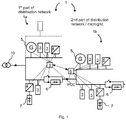
- FIG. 1 illustrates a distribution network 1 that constitutes two parts, a first part 1a connected via a transformer 10 to a power transmission grid, and a second part 1b, which second part is a microgrid, connected to the first part 1a at a PCC (Point of Common Coupling).
- the distribution network 1 comprises a number of assets 3-7, exemplified as loads 3, voltage source converters 4, distributed generators 5, a series capacitor 6 and energy storages 7.
- the energy storages 7 and distributed generators 5 may be connected to the distribution network grid 1 a voltage source converter 4.
- the assets 3-7 are arranged in the first part 1a as well in the microgrid 1b.
- the first part 1a comprises a distribution network controller 9, which is operatively connected to the assets 3-7 of the first part 1a and arranged to monitor the first part 1a of the distribution grid 1, including the PCC.
- the microgrid 1b includes a microgrid controller 8 arranged to monitor the microgrid 1b including the PCC and is operatively connected to the assets 3-7 of the microgrid in order to control these assets 3-7, for example connecting and disconnecting an asset, or adjust settings for the control of a distributed generator 5.
- the distribution network controller 9 and the microgrid controller 8 are communicatively connected to each other.
- Controlling the first part 1a of the distribution network by means of a distribution network controller 9 that monitors the first part 1a of the distribution network from the PCC and upstream is similar to conventional prior art systems.
- Controlling the second part 1b of the distribution network by means of a microgrid controller that monitors the second part 1b, or microgrid, of the distribution network from the PCC and downstream is similar to conventional prior art systems.
- embodiments of the present invention may provide control of a microgrid, the second part 1b, in a grid-connected state, where the second part 1b is connected to the first part 1a, in similar fashion as prior control systems.
- the distribution network controller 9 is configured to monitor and control the assets 3-7 also of the second part 1b (i.e. the microgrid) of the distribution network 1 in addition to monitoring and controlling the assets 3-7 of the first part 1a.
- This monitoring and control of the assets 3-7 in the second part 1b may in embodiments of the invention be performed by the distribution network controller 9 via the microgrid controller 8.
- embodiments of the invention provide an additional mode of control of the assets of the microgrid, i.e. the second part 1b, in the grid-connected state.
- embodiments provide a method of switching between these to control modes, so that the two control modes of the grid-connected state may selectively be used.
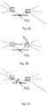
- Figures 2A-C illustrates the first, second and third mode of operation of the microgrid controller.
- the first part 1a is connected to the second part 1b (i.e. the microgrid) at a connection point; the PCC, and the first mode and the second mode constitute selectable modes of operation of the microgrid controller 8 in this grid-connected state.
- the microgrid controller 8 monitors the microgrid including the PCC and controls the assets 3-7 of the microgrid, as indicated with the dotted monitoring and control lines of figure 2A .
- the distribution network controller 9 monitors and controls the first part 1a of the distribution grid 1, including monitoring the PCC.
- the microgrid controller 8 is provided to control the distribution network 1 downstream the PCC, i.e. the second part 1b, and the distribution network controller 9 is provided for controlling the distribution network upstream the PCC, i.e. the first part 1a.
- Both the power flow and voltage are monitored at the PCC, by both the distribution network controller 9 and the microgrid controller 8.
- the status of the connection at the PCC such as the status of an interconnecting breaker (not illustrated) is monitored by both controllers 8 and 9.
- the first 1a and second 1b parts of the distribution network 1 are disconnected from each other at the PCC and the microgrid controller 8 is provided to control the distribution network downstream the PCC, i.e. the microgrid that is also referred to as the second part 1b, and the distribution network controller 9 is provided to control the distribution network upstream the PCC, i.e. the first part 1a.
- the microgrid controller 8 is provided to control the distribution network downstream the PCC, i.e. the microgrid that is also referred to as the second part 1b
- the distribution network controller 9 is provided to control the distribution network upstream the PCC, i.e. the first part 1a.
- FIG. 2B illustrates the second mode of operation wherein the microgrid controller 8 is provided to mediate monitoring and control signals between the microgrid 1b, including the assets 3-7 of the microgrid 8, and the distribution network controller 9.
- the distribution network controller 9 is provided to monitor both the first part 1a and the microgrid 1b (second part) and also control the assets 3-7 of both the first 1a and the second part 1b of the distribution network 1.
- the microgrid controller 8 is provided to monitor and evaluate electrical entities in the microgrid 1b and switch control mode if any electrical entity violates a corresponding threshold for that entity.
- the microgrid controller 8 is configured to provide a monitoring function and regain control of the second part 1b if an electrical entity violates a threshold, for example for safety or stability purposes, or avoiding power losses.
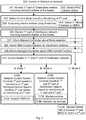
- Figure 3 presents a method 300 of controlling a distribution network 1, especially the assets 3-7 of the distribution network 1, in an embodiment of the present invention.
- the method 300 includes monitoring 306 the first part 1a of the distribution network 1, monitoring 301 the second part 1b of the distribution network and controlling 310 the first part 1a and the second part 1b of the distribution network 1.
- the distribution network controller 9 monitors and controls 310A the first part 1a
- the microgrid controller 8 monitors and controls the second part 1b, which controlling 310 is performed in a "first" control mode.
- These monitoring 301, 306 and controlling 310, 310A are similar to the conventional control of a distribution network 1 that includes, or is connected to, a microgrid (the second part 1b).
- the control of the distribution network 1 is performed by both controllers 8 and 9, each controller 8 or 9 controlling a respective part 1a or 1b of the distribution network 1.
- the control method 300 also includes selecting 303 a control mode.
- the selection 303 of control mode is based on the monitoring 301 of the second part 1b and, in the grid-connected state, either the first control mode 310A or a second control mode 310B is selected.
- the controlling 310 of both the first part 1a and the second part 1b of the distribution network 1 is performed by the distribution network controller 9 on the basis of the monitoring 306 of the first part 1a and the monitoring 301 of the second part 1b.
- the distribution network controller 9 monitors the whole distribution network 1 and controls the assets 3-7 in the whole distribution network 1, i.e. the assets 3-7 downstream, as well as upstream, of the PCC.
- a microgrid such as the second part 1b of the distribution network 1, may also be disconnected and controlled in an island mode.
- the control method 300 also includes such an island mode, or third control mode 310C.
- Islanding may be planned, or may be an un-planned event.
- the monitoring 301 of the second part 1b includes monitoring 302 the connection at the PCC, especially the status of a breaker arranged at the PCC for selectively connecting and dis-connecting the first part 1a and the second part 1b. If the breaker is open, the method includes selecting the third control mode, i.e. the island mode, 310C wherein the distribution network controller controls the first part 1a and the microgrid controller 8 controls the second part 1b.
- Planned islanding may include receiving, by means of the microgrid controller 8, an islanding message from a control system, such as the distribution network controller 9.
- control method 300 of figure 3 also illustrates some optional, but preferred, control measures illustrated within broken lines.
- the selection 302 of control mode includes evaluating 305 electrical entities, as monitored 301 in the second part 1b.
- the evaluating 305 may include comparing the electrical entities using a criterion including threshold bandwidths, and upon detecting a violation selecting the first control mode 310A.
- Each evaluated electric entity have its own respective bandwidth, such as a range, a minimum level or maximum level, and the microgrid controller 8 is configured to select the first control mode 310A when a violation of allowed bandwidth is detected.
- the criteria for mode switching in the grid-connected state may include:
- the criteria for mode switching in the grid-connected state may include:
- the criteria for mode switching in the grid-connected state may include:
- the criteria for mode switching in the grid-connected state may include:
- the criteria for mode switching in the grid-connected state may include:
- the microgrid controller 8 may be further configured to switch back to the first mode of operation when said criteria, e.g. first, second third and fourth, has re-entered, and preferably stabilized, into the acceptable bandwidth again, or has stopped violating the threshold in question.
- criteria e.g. first, second third and fourth
- control measures of the embodiment of figure 3 includes informing 307 the distribution network controller 9 about the selected control mode.
- the selection 303 of control mode is performed by the microgrid controller 8 that suitably inform 307 the distribution network controller 9 about the selection.
- the distribution network controller 9 is suitably selected or configured to employ control functionality in the distribution network 1, preferably so called DMS functionality.
- the distribution network controller 9 preferably selects 308 a specific control function to be employed.
- the distribution network controller 9 is preferably configured to inform 309 the microgrid controller 8 about the selected control function, e.g. the selected DMS function.
- the distribution network controller 9 will subsequently employ the selected DMS function when controlling 310A the first part 1a in accordance with the first mode.
- the distribution network controller 9 will employ the selected DMS function when controlling 310B the first and the second parts 1a, 1b in accordance with the second mode.
- the microgrid controller may support 312A the selected DMS function in view of the received (at 309) indication of DMS function.
- the distribution network controller 9 may inform 309 the microgrid controller 8 about the selected DMS function in both the first and second mode, and also in the third mode, so that the microgrid controller 8 becomes prepared for supporting 312A the DMS function in the first mode
- the distribution network controller 9 may be configured with direct communication for monitoring and controlling of the second part 1b.
- the microgrid controller 8 mediates 313B the monitoring, such as the measurements of electrical entities in the second part 1b is illustrated in figure 3 .
- the microgrid controller 8 mediates 314B control signals, such as control settings for the assets 3-7 of the second part 1b is illustrated in figure 3 .
- the microgrid controller 8 is configured to mediate 313B measured electrical entities and mediate 314B control settings between the second part 1b and the distribution network controller 9 when performing the second control mode 310B.
- the microgrid controller 8 is configured to monitor at least one location in the first part 1a of the distribution network 1, such as an asset 3-7, electrical line or breaker in the distribution network.
- the distribution network controller 9 may be configured to mediate such monitoring, including a measured electrical entity or entities in the distribution network 1.
- such monitoring can be suitable for the microgrid controller 8 and the supporting 312A of DMS functionality may for example be based in part on monitoring an electrical entity at a location in the first part 1a that is remote from the second part 1b.
- the distribution network controller 9 and the microgrid controller 8 may be adapted to mediate measurements of electrical entities to each other, wherein the distribution network controller 9 transfer data of electrical entities of the first part 1a to the microgrid controller 8 and the microgrid controller 8 transfer data of electrical entities in the second part 1b to the distribution network controller 9.
- Such exchange may in addition to measurements include status information of monitored devices in the respective part 1a, 1b of the distribution network 1.
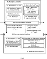
- Figure 4 illustrate an embodiment of a microgrid controller 8 and a distribution network controller 9 for performing the control method of the invention.
- Figure 4 is a simplified illustration of the construction of the controllers 8, 9 and primarily disclose control functions for carrying out said control method, and discloses preferred embodiments for the interaction of the microgrid controller 8 and the distribution network controller 9 when cooperating in carrying out the control method 300 in figure 3 .
- the microgrid controller 8 and the distribution network controller 9 comprises a combination of hardware and software selected and configured for carrying out different functions for the control of a distribution network. These different functions are illustrated as blocks in figure 4 .
- the microgrid controller 8 and the distribution network controller 9 comprises respective communication interfaces 89, 99 for their mutual communication.
- Communication interfaces utilized for monitoring and control of the parts 1a, 1b of a distribution network 1 are not explicitly illustrated in figure 4 . However, such communication may be provided by the same communications interfaces 89, 99, as indicated by horizontal arrows, symbolizing input and output, in figure 4 , and performed by means of a control system network, e.g. a SCADA system, or similar.
- the microgrid controller 8 comprises:
- the controller 80 for the second part is configured to control the second part 1b of the distribution network 1 in the first and third control mode, i.e. in accordance with the first control mode 310A and the third control mode 310C of figure 3 .
- the controller 80 preferably includes a support function 86 configured to supporting 312A the DMS function in the first mode 310A, which DMS function is employed by distribution network controller 9.
- the communication interface 89 is preferably used to receive a "DMS function indication" from the distribution network controller 9, via communication interface 99 of the distribution network controller 9.
- the controller 80 for the second part 1b, of the microgrid controller 8 preferably includes a mediator 85 of control signals configured to mediate 314B control signals, such as settings for the assets 3-7 of the second part 1b during the second control mode 310B.
- the mediator 85 is configured to transfer control signals received from the distribution network controller 9 to the second part 1b of the distribution network 1 during the second control mode 310B.
- the controller 80 is configured to receive the control signals, such as including settings for assets 3-7, such as distributed generators 5, of the second part 1b, from the distribution network controller 9 by means of the communication interfaces 89 and 99, as illustrated in figure 4 .
- the microgrid controller 8 may also receive measurements and status information of the first part 1a of the distribution network from the distribution network controller 9 via the communication interface 89.
- the DMS support function 86 may preferably be adapted to provide supporting 312A of the DMS function on the basis of the measurements and status information received from the distribution network controller 9, in the first control mode 310A.
- the monitor function 81 comprises a mediator 83 of monitoring data, especially status and measurement information, from the monitoring 301 of the second part 1b of the distribution network 1, which mediator 83 is configured to mediate 313B the monitoring data, especially electrical entities, of the second part 1b to the distribution network controller 9 during the second control mode 310B.
- the monitor function 81 is preferably also configured to monitor 302 the connection at the PCC, especially the status of the interconnecting breaker at the PCC.
- the microgrid controller 8 is preferably configured to select 304 the third control mode 310C, for example on the basis of the status of the interconnecting breaker.
- the mode selector 82 is configured to perform the selection 303 of control mode on the basis of the monitoring 301 of the second part 1b of the distribution network 1.
- the mode selector 82 preferably includes an evaluator 84 configured to evaluate 305 one or more electrical entities monitored in the second part 1b, which evaluating 305 is made in view of thresholds of ranges, minimum and/or maximum levels, as disclosed herein with reference to the embodiments of figure 3 .
- the microgrid controller 8 is preferably configured to informing 307 the distribution network controller 9 about the mode selection via the communication interfaces 89, 99, as indicated in figure 4 .
- the mode selector 82 is preferably also configured to select 304 the third control mode 310C, i.e. the island mode, based on monitoring 302 of the PCC status, as illustrated in figure 3 (not illustrated in figure 4 ).
- the mode selector 82 may thus be adapted to select 304 the third control mode 310C when the status of a breaker at the PCC change to "open".
- the distribution network controller 9 comprises main function blocks:
- the distribution network controller 9 is preferably configured to receive a control mode indication (see 307 in figure 3 ), and measurements and status indications concerning the second part 1b of the distribution network 1 from the microgrid controller 8. Also as illustrated, the distribution network controller 9 is configured to transfer a DMS function indication (see 309 in figure 3 ), measurement and status information of the first part 1a, and control signals (see 314B in figure 3 ), in the second control mode 310B, to the microgrid controller 8.
- the present invention has been described with reference to embodiments of the aspects of the invention; a method 300 of controlling a distribution network 1 and a microgrid controller 8 adapted for the method.
- the distribution network 1 comprises assets 3-7 in a first part 1a and a second part 1b. which parts 1a, 1b are selectively connected to each other into an interconnected state at a connection point (PCC).
- the method comprises monitoring 301, 306 and controlling 310 the assets 3-7 of the distribution network 1.
- a first control mode 310A the first part 1a is controlled by a distribution network controller 9 and the second part is controlled by the microgrid controller 8.
- the method includes selecting 303 between controlling 310 the distribution network 1 in the interconnected state in accordance with the first control mode 310A, and controlling 310 the distribution network 1 in the interconnected state in accordance with a second control mode 310B, in which second control mode 310B the assets 3-7 of the both the first part 1a and the second part 1b are controlled by the distribution network controller 9.
- the present invention provides a microgrid control system 8, or microgrid controller, that is configured to extend DMS monitoring and control functions, into the microgrid (second part 1b).
- the microgrid controller 8 is configured to control the microgrid (second part 1b) in an islanded state as well as in a grid-connected state, having two modes of operation in the grid-connected state: a first mode 310A of operation controlling the microgrid autonomously, and a second mode 310B of operation including extending DMS functionality to within the microgrid.
- the microgrid controller 8 is configured to extend DMS monitoring and control in a grid-connected state as long as at least one criterion for microgrid 8 functionality is fulfilled, and to disrupt DMS monitoring and control and act autonomously when at least one of said at least one criterion is violated.
- the microgrid controller 8 is configured to switch between the first 310A and second mode 310B of operation in dependency on the fulfilment or violation of at least one criterion.
- Said criteria for abandoning the DMS extension and control the microgrid autonomously preferably also includes detecting if the breaker at the PCC is open.
- the microgrid controller 8 is configured to monitor the status of the breaker at the PCC and a "fifth" criterion for mode switching is when the status of the PCC breaker opens.
- the microgrid controller 8 switch to island mode; which island mode can be regarded as a third control mode 310C.
- the third control mode 310C may include an islanding phase that leads from the grid-connected state to an islanded state.
- the invention comprises the first control mode 310A and third control mode 310C, wherein the microgrid controller 8 controls the assets of the microgrid, in similar fashion as microgrid controllers of the prior art.
- the microgrid controller 8 can monitor and control the microgrid (1b) when grid-connected (first mode 310A) as well as when islanded (third mode 310C).
- the distribution network controller 9 monitors and controls the distribution network upstream from the microgrid (i.e. the first part 1a). Both the microgrid controller 8 and the distribution network controller 9 preferably monitor the voltage level and power flow at the PCC.
- the second control mode 310B of the microgrid controller 8 includes acting as an extension of the distribution controller 9 to monitor the microgrid 1b and forwarding monitoring data, regarding electrical entities in the microgrid (i.e. second part 1b), to the distribution network controller 9.
- the second control mode 310B of the distribution network controller 9 includes controlling the distribution network 1 including both the first part 1a and the second part 1b, especially the assets 3-7 of both parts 1a, 1b, which controlling is based on monitoring both parts 1a, 1b.
- the change from the second control mode 310B to the third control mode 310C of operation of the microgrid controller 8 is performed when the breaker opens.
- the change (in 303 of figure 3 ) from the second mode 310B of operation to the first mode 310C of operation is performed when at least one predefined criterion for an electric entity deviates (in 305 of figure 3 ) from an acceptable operation bandwidth or violates a maximum or minimum threshold.
Landscapes
- Engineering & Computer Science (AREA)
- Power Engineering (AREA)
- Remote Monitoring And Control Of Power-Distribution Networks (AREA)
- Supply And Distribution Of Alternating Current (AREA)
Abstract
Description
- The present invention relates to electric power system, especially to control of distribution systems that includes a microgrid. An aspect of the present invention provides a microgrid controller.
- A typical electric power system comprises power generators at power plants that produce electric energy. The power system further includes a transmission system with transmission lines, at high voltage e.g. above 140 kV, for transferring the produced electric power to a distribution side of the power system were the electric power is consumed. The transmission system would usually include high voltage lines and the power is transformed down to the power distribution system that uses medium voltage; above 1 kV but below 100 kV, such as between 15 and 45 kV. The distribution system may therefore start with a transformer at a substation and include distribution lines in a grid, or network, for transferring the electric power at medium voltage and low voltage to loads for consumption.
- The distribution system may in addition to loads include other assets, such as distributed generators, energy storages and voltage source converters. The distribution system may therefore include power production facilities, however providing a net consumption of electric power. A distribution system network may also comprise a part that both produces and consumes power and which may run alone; a microgrid. Thus, a distribution network may include a first part connected to a transmission system and a second part that may provide a net production of electrical energy, e.g. a microgrid, which second part is arranged downstream from the first part in the direction from the transmission system and which second part may be disconnected from the first part and run alone by means of distributed generators arranged in the second part, i.e. in the microgrid, but which second part is (usually) not connected to the transmission grid. The second part, or microgrid, is connectable to, and dis-connectable from, the first part by means of a breaker arranged at a so-called PCC (point of common coupling). Thus, the microgrid is connectable to the transmission grid via the first part of the distribution network.
- For the control of the electric power in the distribution grid, the distribution grid may be provided with a network control system, or distribution network controller, such as a distribution network controller using a Distribution Management System (DMS). A DMS comprises software for analyzing measurements and controlling a network, and in general DMS provides functionality to monitor a distribution network and to control a distribution network. A DMS suitably includes a Volt-VAR control (VVC) that monitors and control voltage levels and reactive power in the distribution network, for example by means of controlling tap-changers and series capacitors. A DMS suitably also includes a Load Shedding application (LSA) in order to disconnect loads in the distribution system in cases of undesired electrical conditions in the distribution network. Also, a DMS may provide power flow control and fault management. DMS may provide an automated network control as well as providing network data for operators by means of GUI (Graphical User Interface).
- The distribution network controller can utilize DMS to monitor the distribution network between the transformer connecting the distribution network to the transmission network and the PCC connecting the distribution network to the microgrid; i.e. monitor the first part of the distribution network. Based on the monitoring of the first part of the distribution network, the assets of the first part of the distribution network are controlled, such as energy storages, controllable loads, tap change transformers, distributed generators, and controlled series capacitors.
- A microgrid is normally provided with a microgrid controller, being a central controller or a controller distributed among assets of the microgrid. The microgrid controller would normally monitor a second part of the distribution network, from the PCC and downstream, e.g. monitor the voltage level and the power flow at the PCC, and monitor electrical entities at several locations within the microgrid, or second part, such as the voltage and current in transfer lines, or cables, at generators, at loads and at transformers within the microgrid. The microgrid controller may provide voltage level control, reactive power control, load shedding, power flow control and active power balancing within the microgrid network when the microgrid is grid-connected as well as when the microgrid is disconnected from the rest of the distribution grid, i.e. when the microgrid is islanded.
- Thus, a typical distribution network that includes a microgrid, may in general comprise a distribution network controller provided to monitor and control assets in a first part of the distribution network from the PCC and upstream, whereas a microgrid controller is provided to monitor a second part of the distribution network; the microgrid, from the PCC and downstream. The microgrid controller may be used to control the power flow at the PCC, i.e. between the microgrid and the first part of the distribution network.
- A microgrid usually optimize its own operation and does not surge for the overall functioning of the distribution system.
US2017/016071 (E1 ) aims at solving the problem that microgrids do not interoperate with distribution management systems (DMS), see §0004 and §0005 of E1. An idea in E1 is that the microgrid should contribute to the "overall power grid optimization" (§0025). E1 presents examples of what should be achieved by means of the microgrid; e.g. contribute to reactive power in the distribution grid (§0012, §0036), volt/VAR control (§0023, §0032) and "energy and cost optimization" (§0024). In order to reach these goals, the microgrid of E1 has been adapted to operate in a so called "VPP mode" (referring to Virtual Power Plant" in §0030), where the microgrid is used to inject active and reactive power, and to support voltage and frequency (§0036 of E1). - A disadvantage with the virtual power plant suggested in E1 is that the control scheme of E1 tends to be complicated and if the microgrid is subjected to sudden topological or electrical variations, operations may become unstable which may cause a blackout or disconnection of the microgrid. Moreover, viewing a microgrid as a Virtual Power Plant is a simplification, since a microgrid usually is more complex than a power plant. A microgrid may also include several distributed generators including e.g. distributed generators with varying power output, for example from a renewable source like a solar PV plant or wind power plant and viewing the microgrid as a VPP may lead to a use of the microgrid in much less optimized way than a conventional control by means of a dedicated microgrid controller may provide. The VPP operation aims to support the distribution grid by achieving a setpoint for the microgrid at the PCC, and such operation can contribute to provide optimization functions for the distribution network upstream the PCC, but may negatively affect the microgrid.
- An aim of the present invention is to provide an alternative to the control of a microgrid without the drawbacks of the prior art. For this purpose, aspects of the present invention provide means to extend control of a distribution network into a microgrid that is connected to the distribution network.
- According to a first aspect, the present invention provides a method of controlling assets in a distribution network, which distribution network comprises a first part and a second part, which first and second part comprise assets, such as generators and loads. The first part and the second part of the distribution network are selectively connected to each other into an interconnected state. The distribution network further comprises a network controller and a microgrid controller. The method comprises monitoring the distribution network, including electrical entities in the distribution network and controlling the assets of the distribution network based on the monitoring. The controlling further includes controlling the assets of the distribution network in the interconnected state in accordance with a first control mode, wherein the assets of the first part are controlled by the distribution network controller and the assets of the second part are controlled by the microgrid controller.
- Especially, the method of the first aspect comprises selecting between controlling the assets of the distribution network in the interconnected state in accordance with the first mode, and controlling the assets of the distribution network in the interconnected state in accordance with a second control mode, in which second mode the assets of the first part and the assets of the second part are controlled by the distribution network controller.
- Using a second mode, wherein the second part is controlled by the distribution network controller, it contributes to a better performance in the control of the distribution network. The control, in the first mode, of the second part by means of the microgrid controller, provides a fallback for controlling the second part in the grid-connected state. Unsuitable control of the second part, or microgrid, may more easily be avoided than in prior art systems.
- In an embodiment of the first aspect, the selection is performed by the microgrid controller.
- Letting the microgrid controller effectuate the mode switches, contributes to a facilitated implementation in different distribution network control systems, since main functionality may be provided by the microgrid controller when adding a microgrid to the distribution network.
- In an embodiment of the first aspect, the selection includes evaluating at least one electrical entity of the second part of the distribution network and switching from the second mode to the first mode when any electrical entity violates a threshold bandwidth for that electrical entity.
- In a further embodiment, the evaluated at least one electrical entity of the second part comprises at least one of the following:
- the voltage level at the connection (PCC) between the distribution network and the microgrid,
- the reactive power flow between the first part of the distribution network and the second part of the distribution network,
- the active power flow between the first part of the distribution network and the second part of the distribution network,
- the voltage level at an asset within the second part of the distribution network, and
- the current from an asset of the second part of the distribution network.
- An embodiment of the first aspect includes
- selecting a specific control function, such as a so called DMS function (Distribution Management System), for the distribution network controller, and
- controlling the assets in the first part in the first mode in accordance with the control function, or
- controlling the assets in the distribution network, i.e. the first and second part, in the second mode in accordance with the control function.
- In this embodiment the first mode, and/or the second mode, may further include informing the microgrid controller which specific control function is currently used by the distribution network controller. In this way, the microgrid controller may be adapted to contribute to performing the selected DMS function when in control of the second part, so that the second part, or microgrid, may support the first part of the distribution network. For example, when being informed that the distribution network controller in the second mode provides a DMS function such as voltage control, the second part may after switching to the first mode contribute to the DMS function by supporting the voltage level at the PCC, still controlling the microgrid based on measurements in the microgrid.
- In an embodiment of the first aspect, a breaker is arranged at the PCC and the monitoring of the second part of the distribution network includes monitoring the status of the breaker, and the method further includes switching to a third control mode when the breaker opens, in which third control mode the second part is controlled as an islanded microgrid by the microgrid controller.
- According to a second aspect, the present invention provides a microgrid controller for controlling a part, especially a microgrid, of a distribution network. A distribution network that comprises a first part and a second part each of which comprises assets, and wherein the first part and said second part is selectively connected to each other into an interconnected state at a connection point (PCC). The distribution network further comprises a network controller. The microgrid controller comprises:
- a monitoring functionality, or monitoring means, configured to monitor the second part of the distribution network,
- a controller configured to control assets in the second part of the distribution network based on the monitoring of the second part, and which controlling is performed in accordance with a first control mode in said interconnected state. Especially, the microgrid controller comprises:
- a mode selector configured to select between controlling the assets of the second part of the distribution network in the interconnected state in accordance with the first mode, and controlling the assets of the second part of the distribution network in the interconnected state in accordance with a second control mode, in which second control mode the assets of the second part are controlled by the distribution network controller, and
- a mediator of monitored data configured to mediate monitored data in the second control mode to the distribution network controller.
- Thus, the microgrid controller is configured to select control mode based on the monitoring of the second part by means of the monitor function and to mediate data retrieved during the monitoring of the second part to the distribution network controller in the second control mode.
- In an embodiment of the second aspect, the microgrid controller further comprises an evaluator configured to evaluate at least one electrical entity of the second part of the distribution network in view of respective threshold bandwidth for each evaluated electrical entity, wherein the mode selector is adapted to switch from the second control mode to the first control mode when an electrical entity violates the threshold bandwidth for that electrical entity.
- In an embodiment of the second aspect, the evaluated at least one electrical entity of the second part comprises at least one of the following:
- the voltage level at the connection (PCC) between the first part of the distribution network and the second part of the distribution network,
- the reactive power flow between the first part of the distribution network and the second part of the distribution network,
- the active power flow between the first part of the distribution network and the second part of the distribution network,
- the voltage level at an asset in the second part of the distribution network, or
- the current from an asset in the second part of the distribution network.
- In an embodiment of the second aspect, the mode selector is adapted to switch back from the first control mode to the second control mode when an evaluated electrical entity has re-entered the threshold bandwidth for that electrical entity, and, preferably stayed within the bandwidth for a predefined time.
- Thus, the microgrid controller is configured to switch back when the monitored and evaluated electrical entity no longer violates the threshold, and preferably has remained within the bandwidth and stabilized a preset time period.
- In an embodiment of the second aspect, the monitoring means is adapted to monitor the status of a breaker arranged at the PCC for the interconnection of the first part and the second part of the distribution network. In this embodiment, the mode selector is adapted to switch to a third control mode when the breaker opens, and the microgrid controller is configured to control the second part in accordance with the third control mode as an islanded microgrid.
- In an embodiment of the second aspect, the microgrid controller further comprises a mediator of control signals configured to mediate control settings from the distribution network controller to the assets of the second part of the distribution network, especially to distributed generators, voltage source converters and/or energy storages of the second part.
-
-
Figure 1 illustrates a distribution network that includes a microgrid; -
Figures 2A-C illustrate three control modes; -
Figure 3 illustrates an embodiment of a method of controlling a microgrid and a distribution network; -
Figure 4 illustrates an embodiment of a microgrid controller, and a network controller. -
Figure 1 illustrates adistribution network 1 that constitutes two parts, afirst part 1a connected via atransformer 10 to a power transmission grid, and asecond part 1b, which second part is a microgrid, connected to thefirst part 1a at a PCC (Point of Common Coupling). Thedistribution network 1 comprises a number of assets 3-7, exemplified asloads 3,voltage source converters 4, distributed generators 5, aseries capacitor 6 andenergy storages 7. Theenergy storages 7 and distributed generators 5 may be connected to thedistribution network grid 1 avoltage source converter 4. The assets 3-7 are arranged in thefirst part 1a as well in themicrogrid 1b. Thefirst part 1a comprises adistribution network controller 9, which is operatively connected to the assets 3-7 of thefirst part 1a and arranged to monitor thefirst part 1a of thedistribution grid 1, including the PCC. Themicrogrid 1b includes amicrogrid controller 8 arranged to monitor themicrogrid 1b including the PCC and is operatively connected to the assets 3-7 of the microgrid in order to control these assets 3-7, for example connecting and disconnecting an asset, or adjust settings for the control of a distributed generator 5. Thedistribution network controller 9 and themicrogrid controller 8 are communicatively connected to each other. - Controlling the
first part 1a of the distribution network by means of adistribution network controller 9 that monitors thefirst part 1a of the distribution network from the PCC and upstream is similar to conventional prior art systems. Controlling thesecond part 1b of the distribution network by means of a microgrid controller that monitors thesecond part 1b, or microgrid, of the distribution network from the PCC and downstream is similar to conventional prior art systems. Thus, embodiments of the present invention may provide control of a microgrid, thesecond part 1b, in a grid-connected state, where thesecond part 1b is connected to thefirst part 1a, in similar fashion as prior control systems. - However, according to the embodiments of the present invention, the
distribution network controller 9 is configured to monitor and control the assets 3-7 also of thesecond part 1b (i.e. the microgrid) of thedistribution network 1 in addition to monitoring and controlling the assets 3-7 of thefirst part 1a. This monitoring and control of the assets 3-7 in thesecond part 1b may in embodiments of the invention be performed by thedistribution network controller 9 via themicrogrid controller 8. Thus, embodiments of the invention provide an additional mode of control of the assets of the microgrid, i.e. thesecond part 1b, in the grid-connected state. Also, embodiments provide a method of switching between these to control modes, so that the two control modes of the grid-connected state may selectively be used. -
Figures 2A-C illustrates the first, second and third mode of operation of the microgrid controller. In the first and second mode of operation, thefirst part 1a is connected to thesecond part 1b (i.e. the microgrid) at a connection point; the PCC, and the first mode and the second mode constitute selectable modes of operation of themicrogrid controller 8 in this grid-connected state. - In the first mode of operation, the
microgrid controller 8 monitors the microgrid including the PCC and controls the assets 3-7 of the microgrid, as indicated with the dotted monitoring and control lines offigure 2A . Thedistribution network controller 9 monitors and controls thefirst part 1a of thedistribution grid 1, including monitoring the PCC. Themicrogrid controller 8 is provided to control thedistribution network 1 downstream the PCC, i.e. thesecond part 1b, and thedistribution network controller 9 is provided for controlling the distribution network upstream the PCC, i.e. thefirst part 1a. Both the power flow and voltage are monitored at the PCC, by both thedistribution network controller 9 and themicrogrid controller 8. Also, the status of the connection at the PCC, such as the status of an interconnecting breaker (not illustrated) is monitored by bothcontrollers - In the third mode of operation illustrated in
figure 2C , the first 1a and second 1b parts of thedistribution network 1 are disconnected from each other at the PCC and themicrogrid controller 8 is provided to control the distribution network downstream the PCC, i.e. the microgrid that is also referred to as thesecond part 1b, and thedistribution network controller 9 is provided to control the distribution network upstream the PCC, i.e. thefirst part 1a. In this case there is no power flow at the PCC and only the voltage is monitored on both sides of the PCC. -
Figure 2B illustrates the second mode of operation wherein themicrogrid controller 8 is provided to mediate monitoring and control signals between themicrogrid 1b, including the assets 3-7 of themicrogrid 8, and thedistribution network controller 9. Thedistribution network controller 9 is provided to monitor both thefirst part 1a and themicrogrid 1b (second part) and also control the assets 3-7 of both the first 1a and thesecond part 1b of thedistribution network 1. In this second operating mode, themicrogrid controller 8 is provided to monitor and evaluate electrical entities in themicrogrid 1b and switch control mode if any electrical entity violates a corresponding threshold for that entity. Thus, themicrogrid controller 8 is configured to provide a monitoring function and regain control of thesecond part 1b if an electrical entity violates a threshold, for example for safety or stability purposes, or avoiding power losses. -
Figure 3 presents amethod 300 of controlling adistribution network 1, especially the assets 3-7 of thedistribution network 1, in an embodiment of the present invention. Themethod 300 includes monitoring 306 thefirst part 1a of thedistribution network 1, monitoring 301 thesecond part 1b of the distribution network and controlling 310 thefirst part 1a and thesecond part 1b of thedistribution network 1. In more detail, thedistribution network controller 9 monitors and controls 310A thefirst part 1a, and themicrogrid controller 8 monitors and controls thesecond part 1b, which controlling 310 is performed in a "first" control mode. These monitoring 301, 306 and controlling 310, 310A are similar to the conventional control of adistribution network 1 that includes, or is connected to, a microgrid (thesecond part 1b). Thus, in the first control mode (310A), the control of thedistribution network 1 is performed by bothcontrollers controller respective part distribution network 1. - The
control method 300 also includes selecting 303 a control mode. In short, theselection 303 of control mode is based on the monitoring 301 of thesecond part 1b and, in the grid-connected state, either thefirst control mode 310A or asecond control mode 310B is selected. In thesecond control mode 310B, the controlling 310 of both thefirst part 1a and thesecond part 1b of thedistribution network 1 is performed by thedistribution network controller 9 on the basis of the monitoring 306 of thefirst part 1a and the monitoring 301 of thesecond part 1b. Thus, thedistribution network controller 9 monitors thewhole distribution network 1 and controls the assets 3-7 in thewhole distribution network 1, i.e. the assets 3-7 downstream, as well as upstream, of the PCC. - A microgrid, such as the
second part 1b of thedistribution network 1, may also be disconnected and controlled in an island mode. Thecontrol method 300 also includes such an island mode, orthird control mode 310C. Islanding may be planned, or may be an un-planned event. To prepare for an un-planned event, the monitoring 301 of thesecond part 1b includes monitoring 302 the connection at the PCC, especially the status of a breaker arranged at the PCC for selectively connecting and dis-connecting thefirst part 1a and thesecond part 1b. If the breaker is open, the method includes selecting the third control mode, i.e. the island mode, 310C wherein the distribution network controller controls thefirst part 1a and themicrogrid controller 8 controls thesecond part 1b. Planned islanding may include receiving, by means of themicrogrid controller 8, an islanding message from a control system, such as thedistribution network controller 9. - The embodiment of the
control method 300 offigure 3 also illustrates some optional, but preferred, control measures illustrated within broken lines. Preferably, theselection 302 of control mode includes evaluating 305 electrical entities, as monitored 301 in thesecond part 1b. The evaluating 305 may include comparing the electrical entities using a criterion including threshold bandwidths, and upon detecting a violation selecting thefirst control mode 310A. Each evaluated electric entity have its own respective bandwidth, such as a range, a minimum level or maximum level, and themicrogrid controller 8 is configured to select thefirst control mode 310A when a violation of allowed bandwidth is detected. - Some examples on monitored and evaluated electric entities are given in the following.
- The criteria for mode switching in the grid-connected state may include:
- monitoring the power balance within the microgrid (
second part 1b) and switching to thefirst mode 310A of operation of the microgrid when the power balance of the microgrid (1b) violates a first threshold, which first threshold is a power balancing threshold. Thefirst mode 310A of operation may preferably include power balancing of the microgrid (1b). - The criteria for mode switching in the grid-connected state may include:
- monitoring the voltage level within the microgrid (1b) and switching to the
first mode 310A of operation when a second threshold is reached, which second threshold is a voltage level threshold. Thefirst mode 310A of operation preferably includes voltage control in themicrogrid 1b. - The criteria for mode switching in the grid-connected state may include:
- monitoring the reactive power and switching to the
first mode 310A of operation when a third threshold is reached, which third threshold is a reactive power threshold. Thefirst mode 310A of operation preferably includes reactive power control in themicrogrid 1b. - The criteria for mode switching in the grid-connected state may include:
- monitoring the voltage level and reactive power within the
microgrid 1b and switching to thefirst mode 310A when the second and/or the third thresholds is/are reached. Thefirst mode 310A may preferably include VVC (Volt-VAR Control) of themicrogrid 1b, and/or thefirst part 1a. Thefirst mode 310A may include Volt-VAR optimization in the microgrid (1b), or thefirst part 1a, including VCC and for example simultaneously keeping system losses, or voltage drops, to a minimum. - The criteria for mode switching in the grid-connected state may include:
- monitoring the harmonics in the
microgrid 1b and switching to thefirst mode 310A of operation when a fourth threshold is reached, which fourth threshold is a threshold of harmonics. The first mode 310a of operation may preferably include counteracting harmonics in the microgrid. - The
microgrid controller 8 may be further configured to switch back to the first mode of operation when said criteria, e.g. first, second third and fourth, has re-entered, and preferably stabilized, into the acceptable bandwidth again, or has stopped violating the threshold in question. - Further suitable control measures of the embodiment of
figure 3 includes informing 307 thedistribution network controller 9 about the selected control mode. Theselection 303 of control mode is performed by themicrogrid controller 8 that suitably inform 307 thedistribution network controller 9 about the selection. - The
distribution network controller 9 is suitably selected or configured to employ control functionality in thedistribution network 1, preferably so called DMS functionality. Thedistribution network controller 9 preferably selects 308 a specific control function to be employed. Also, thedistribution network controller 9 is preferably configured to inform 309 themicrogrid controller 8 about the selected control function, e.g. the selected DMS function. Thedistribution network controller 9 will subsequently employ the selected DMS function when controlling 310A thefirst part 1a in accordance with the first mode. Thedistribution network controller 9 will employ the selected DMS function when controlling 310B the first and thesecond parts distribution network controller 9 may inform 309 themicrogrid controller 8 about the selected DMS function in both the first and second mode, and also in the third mode, so that themicrogrid controller 8 becomes prepared for supporting 312A the DMS function in thefirst mode 310A. - The
distribution network controller 9 may be configured with direct communication for monitoring and controlling of thesecond part 1b. However, a preferred embodiment wherein themicrogrid controller 8 mediates 313B the monitoring, such as the measurements of electrical entities in thesecond part 1b is illustrated infigure 3 . Also, a preferred embodiment wherein themicrogrid controller 8 mediates 314B control signals, such as control settings for the assets 3-7 of thesecond part 1b is illustrated infigure 3 . Thus, themicrogrid controller 8 is configured to mediate 313B measured electrical entities and mediate 314B control settings between thesecond part 1b and thedistribution network controller 9 when performing thesecond control mode 310B. - In a further embodiment (not illustrated in
figure 3 ), themicrogrid controller 8 is configured to monitor at least one location in thefirst part 1a of thedistribution network 1, such as an asset 3-7, electrical line or breaker in the distribution network. Thedistribution network controller 9 may be configured to mediate such monitoring, including a measured electrical entity or entities in thedistribution network 1. When supporting 312A the DMS function performed by thedistribution network controller 9 in thefirst part 1a, such monitoring can be suitable for themicrogrid controller 8 and the supporting 312A of DMS functionality may for example be based in part on monitoring an electrical entity at a location in thefirst part 1a that is remote from thesecond part 1b. Thus, thedistribution network controller 9 and themicrogrid controller 8 may be adapted to mediate measurements of electrical entities to each other, wherein thedistribution network controller 9 transfer data of electrical entities of thefirst part 1a to themicrogrid controller 8 and themicrogrid controller 8 transfer data of electrical entities in thesecond part 1b to thedistribution network controller 9. Such exchange may in addition to measurements include status information of monitored devices in therespective part distribution network 1. -
Figure 4 illustrate an embodiment of amicrogrid controller 8 and adistribution network controller 9 for performing the control method of the invention.Figure 4 is a simplified illustration of the construction of thecontrollers microgrid controller 8 and thedistribution network controller 9 when cooperating in carrying out thecontrol method 300 infigure 3 . Themicrogrid controller 8 and thedistribution network controller 9 comprises a combination of hardware and software selected and configured for carrying out different functions for the control of a distribution network. These different functions are illustrated as blocks infigure 4 . Themicrogrid controller 8 and thedistribution network controller 9 comprises respective communication interfaces 89, 99 for their mutual communication. Communication interfaces utilized for monitoring and control of theparts distribution network 1 are not explicitly illustrated infigure 4 . However, such communication may be provided by the same communications interfaces 89, 99, as indicated by horizontal arrows, symbolizing input and output, infigure 4 , and performed by means of a control system network, e.g. a SCADA system, or similar. - As main function blocks, the
microgrid controller 8 comprises: - a
controller 80 configured to control thesecond part 1b, especially a microgrid, of adistribution network 1, - a monitoring function, or monitor, 81 configured to monitor the
second part 1b of the distribution network, - a
mode selector 82 for selecting control mode for the distribution network, and acommunication interface 89 configured for exchanging information with thedistribution network controller 9. - The
controller 80 for the second part is configured to control thesecond part 1b of thedistribution network 1 in the first and third control mode, i.e. in accordance with thefirst control mode 310A and thethird control mode 310C offigure 3 . Thecontroller 80 preferably includes a support function 86 configured to supporting 312A the DMS function in thefirst mode 310A, which DMS function is employed bydistribution network controller 9. As indicated infigure 4 , thecommunication interface 89 is preferably used to receive a "DMS function indication" from thedistribution network controller 9, viacommunication interface 99 of thedistribution network controller 9. Thecontroller 80 for thesecond part 1b, of themicrogrid controller 8, preferably includes amediator 85 of control signals configured to mediate 314B control signals, such as settings for the assets 3-7 of thesecond part 1b during thesecond control mode 310B. Themediator 85 is configured to transfer control signals received from thedistribution network controller 9 to thesecond part 1b of thedistribution network 1 during thesecond control mode 310B. Thecontroller 80 is configured to receive the control signals, such as including settings for assets 3-7, such as distributed generators 5, of thesecond part 1b, from thedistribution network controller 9 by means of the communication interfaces 89 and 99, as illustrated infigure 4 . Themicrogrid controller 8 may also receive measurements and status information of thefirst part 1a of the distribution network from thedistribution network controller 9 via thecommunication interface 89. The DMS support function 86 may preferably be adapted to provide supporting 312A of the DMS function on the basis of the measurements and status information received from thedistribution network controller 9, in thefirst control mode 310A. - The
monitor function 81 comprises a mediator 83 of monitoring data, especially status and measurement information, from the monitoring 301 of thesecond part 1b of thedistribution network 1, which mediator 83 is configured to mediate 313B the monitoring data, especially electrical entities, of thesecond part 1b to thedistribution network controller 9 during thesecond control mode 310B. - The
monitor function 81 is preferably also configured to monitor 302 the connection at the PCC, especially the status of the interconnecting breaker at the PCC. In an unplanned islanding of thesecond part 1b, themicrogrid controller 8 is preferably configured to select 304 thethird control mode 310C, for example on the basis of the status of the interconnecting breaker. - The
mode selector 82 is configured to perform theselection 303 of control mode on the basis of the monitoring 301 of thesecond part 1b of thedistribution network 1. Themode selector 82 preferably includes anevaluator 84 configured to evaluate 305 one or more electrical entities monitored in thesecond part 1b, which evaluating 305 is made in view of thresholds of ranges, minimum and/or maximum levels, as disclosed herein with reference to the embodiments offigure 3 . Themicrogrid controller 8 is preferably configured to informing 307 thedistribution network controller 9 about the mode selection via the communication interfaces 89, 99, as indicated infigure 4 . - The
mode selector 82 is preferably also configured to select 304 thethird control mode 310C, i.e. the island mode, based on monitoring 302 of the PCC status, as illustrated infigure 3 (not illustrated infigure 4 ). Themode selector 82 may thus be adapted to select 304 thethird control mode 310C when the status of a breaker at the PCC change to "open". - The
distribution network controller 9 comprises main function blocks: - a
controller 90 configured to control 310 assets 3-7 in thedistribution network 1, especially - assets 3-7 in the
first part 1a in the first, and third,control mode 310A/C, and - assets 3-7 in both the first and
second parts second control mode 310B, - a
monitor function 91 configured to monitor thefirst part 1a of thedistribution network 1, - a DMS selector configured to select 308 control function for the
control 310 of the distribution network, especially select 308 a control function - to control 310 the
first part 1a in thefirst mode 310A, and - to control 310 the first and
second parts second mode 310B, and - a
communication interface 99 configured for communicating with themicrogrid controller 8, and preferably also for monitoring 306 thefirst part 1a of thedistribution network 1 and control 310 the assets 3-7 of thefirst part 1a of the distribution network. - As further illustrated in
figure 4 , thedistribution network controller 9 is preferably configured to receive a control mode indication (see 307 infigure 3 ), and measurements and status indications concerning thesecond part 1b of thedistribution network 1 from themicrogrid controller 8. Also as illustrated, thedistribution network controller 9 is configured to transfer a DMS function indication (see 309 infigure 3 ), measurement and status information of thefirst part 1a, and control signals (see 314B infigure 3 ), in thesecond control mode 310B, to themicrogrid controller 8. - The present invention has been described with reference to embodiments of the aspects of the invention; a
method 300 of controlling adistribution network 1 and amicrogrid controller 8 adapted for the method. Thedistribution network 1 comprises assets 3-7 in afirst part 1a and a second part 1b. whichparts distribution network 1. In afirst control mode 310A, thefirst part 1a is controlled by adistribution network controller 9 and the second part is controlled by themicrogrid controller 8. Especially, the method includes selecting 303 between controlling 310 thedistribution network 1 in the interconnected state in accordance with thefirst control mode 310A, and controlling 310 thedistribution network 1 in the interconnected state in accordance with asecond control mode 310B, in whichsecond control mode 310B the assets 3-7 of the both thefirst part 1a and thesecond part 1b are controlled by thedistribution network controller 9. - The present invention provides a
microgrid control system 8, or microgrid controller, that is configured to extend DMS monitoring and control functions, into the microgrid (second part 1b). Themicrogrid controller 8 is configured to control the microgrid (second part 1b) in an islanded state as well as in a grid-connected state, having two modes of operation in the grid-connected state: afirst mode 310A of operation controlling the microgrid autonomously, and asecond mode 310B of operation including extending DMS functionality to within the microgrid. Themicrogrid controller 8 is configured to extend DMS monitoring and control in a grid-connected state as long as at least one criterion formicrogrid 8 functionality is fulfilled, and to disrupt DMS monitoring and control and act autonomously when at least one of said at least one criterion is violated. Themicrogrid controller 8 is configured to switch between the first 310A andsecond mode 310B of operation in dependency on the fulfilment or violation of at least one criterion. - Said criteria for abandoning the DMS extension and control the microgrid autonomously preferably also includes detecting if the breaker at the PCC is open. Thus, the
microgrid controller 8 is configured to monitor the status of the breaker at the PCC and a "fifth" criterion for mode switching is when the status of the PCC breaker opens. When the breaker is open, themicrogrid controller 8 switch to island mode; which island mode can be regarded as athird control mode 310C. Thethird control mode 310C may include an islanding phase that leads from the grid-connected state to an islanded state. - The invention comprises the
first control mode 310A andthird control mode 310C, wherein themicrogrid controller 8 controls the assets of the microgrid, in similar fashion as microgrid controllers of the prior art. Thus, themicrogrid controller 8 can monitor and control the microgrid (1b) when grid-connected (first mode 310A) as well as when islanded (third mode 310C). During the first 310A andthird mode 310C of operation, thedistribution network controller 9 monitors and controls the distribution network upstream from the microgrid (i.e. thefirst part 1a). Both themicrogrid controller 8 and thedistribution network controller 9 preferably monitor the voltage level and power flow at the PCC. - A difference with the invention compared to prior art is that the
microgrid controller 8 and thedistribution network controller 9 can function in thesecond control mode 310B. Thesecond control mode 310B of themicrogrid controller 8 includes acting as an extension of thedistribution controller 9 to monitor themicrogrid 1b and forwarding monitoring data, regarding electrical entities in the microgrid (i.e.second part 1b), to thedistribution network controller 9. Thesecond control mode 310B of thedistribution network controller 9 includes controlling thedistribution network 1 including both thefirst part 1a and thesecond part 1b, especially the assets 3-7 of bothparts parts second control mode 310B to thethird control mode 310C of operation of themicrogrid controller 8 is performed when the breaker opens. In the embodiments of the present invention, the change (in 303 offigure 3 ) from thesecond mode 310B of operation to thefirst mode 310C of operation is performed when at least one predefined criterion for an electric entity deviates (in 305 offigure 3 ) from an acceptable operation bandwidth or violates a maximum or minimum threshold. - The present invention is, however, not limited to the presented embodiments. The scope of the invention being defined with the attached claims, within which scope the invention may be provided in various forms by the skilled person.
Claims (12)
- Method (300) of controlling a distribution network (1) comprising a first part (1a) and a second part (1b), each of said parts (1a; 1b) comprising assets (3-7), said first part (1a) and said second part (1b) being selectively connected to each other into an interconnected state at a connection point (PCC), said distribution network (1) further comprising a distribution network controller (9) and a microgrid controller (8),
the method comprises monitoring (301, 306) the distribution network (1), including electrical entities of the distribution network (1);
controlling (310) the assets (3-7) of the distribution network (1) based on the monitoring (301, 306);
the controlling (310) further includes controlling (310) the assets (3-7) of the distribution network (1) in the interconnected state in accordance with a first control mode (310A), wherein the assets (3-7) of the first part (1a) are controlled by the distribution network controller (9) and the assets (3-7) of the second part (1b) are controlled by the microgrid controller (8),
the method is
characterized in comprising
selecting (303) between- controlling (310) the assets of the distribution network (1) in the interconnected state in accordance with the first control mode (310A), and- controlling (310) the assets (3-7) of the distribution network (1) in the interconnected state in accordance with a second control mode (310B), in which the assets (3-7) of the first part (1a) and the assets (3-7) of the second part (1b) are controlled by the distribution network controller (9). - Method according to claim 1, wherein the selecting (303) is performed by the microgrid controller (8).
- Method according to claim 1 or 2, wherein the selecting (303) includes evaluating (305) at least one electric entity of the second part (1b) of the distribution network (1) in view of a respective threshold bandwidth for each evaluated electrical entity, and switching from the second control mode (310B) to the first control mode (310A) when any electrical entity violates a threshold bandwidth for that electrical entity.
- Method according to claim 3, wherein the evaluated at least one electrical entity of the second part (1b) comprises at least one of the following:- the voltage level at the connection (PCC) between the first part (1a) of the distribution network and the second part (1b) of the distribution network (1),- the reactive power flow between the first part (1a) of the distribution network and the second part (1b) of the distribution network (1),- the active power flow between the first part (1a) of the distribution network and the second part (1b) of the distribution network (1),- the voltage level at an asset (3-7) in the second part (1b) of the distribution network (1), or- the current from an asset (3-7) in the second part (1b) of the distribution network (1).
- Method according to any of claims 1 to 4, including- selecting (308) a specific control function for the distribution network controller (9), and- controlling (310) the assets (3-7) in the first part (1a) in the first mode (310A), and controlling (310) the assets (3-7) in the distribution network (1) in the second mode (310B) in accordance with the control function,wherein the first mode (310A), or the second mode (310B), further includes informing (311) the microgrid controller (8) which specific control function currently used by the distribution network controller (9).
- Method according to any of claims 1 to 4, wherein a breaker is arranged at the PCC and the monitoring (301) of the second part of the distribution network (1) includes monitoring (302) the status of the breaker, and the method further includes switching (304) to a third control mode (310C) when the breaker opens, in which third control mode (310C) the second part (1b) is controlled as an islanded microgrid by the microgrid controller (8).
- A microgrid controller (8) for controlling a part of a distribution network (1), which distribution network (1) comprises a first part (1a) and a second part (1b) that comprises assets (3-7), said first part (1a) and said second part (1b) being selectively connected to each other into an interconnected state at a connection point (PCC), and said distribution network (1) further comprising a distribution network controller (9), said microgrid controller (8) comprising:- a monitor function (81) configured to monitor (301) the second part (1b) of the distribution network (1),- a controller (80) configured to control (310) assets (3-7) in the second part (1b) of the distribution network (1) based on the monitoring (301) of the second part (1b), which controlling (310) is performed in accordance with a first control mode (310A) in said interconnected state,
characterized in comprising- a mode selector (82) configured to select (303) between- controlling (310) the assets (3-7) of the second part (1b) of the distribution network (1) in the interconnected state in accordance with the first mode (310A), and- controlling (310) the assets (3-7) of the second part (1b) of the distribution network (1) in the interconnected state in accordance with a second control mode (310B), in which the assets (3-7) of the second part (1b) are controlled by the distribution network controller (9), and- a mediator (83) of monitored data configured to mediate (313B) monitored data in the second control mode (310B) to the distribution network controller (9). - A microgrid controller (8) according to claim 7, further comprising an evaluator (84) configured to evaluate (305) at least one electrical entity of the second part (1b) of the distribution network (1) in view of a respective threshold bandwidth for each evaluated electrical entity, wherein the mode selector (82) is adapted to switch from the second control mode (310B) to the first control mode (310A) when any electrical entity violates the threshold bandwidth for that electrical entity.
- A microgrid controller (8) according to claim 8, wherein the evaluated at least one electrical entity of the second part (1b) comprises at least one of the following:- the voltage level at the connection (PCC) between the first part (1a) of the distribution network and the second part (1b) of the distribution network (1),- the reactive power flow between the first part (1a) of the distribution network and the second part (1b) of the distribution network (1),- the active power flow between the first part (1a) of the distribution network and the second part (1b) of the distribution network (1),- the voltage level at an asset (3-7) in the second part (1b) of the distribution network (1), or- the current from an asset (3-7) in the second part (1b) of the distribution network (1).
- A microgrid controller (8) according to claim 8, wherein the mode selector (82) is adapted to switch back from the first control mode (310A) to the second control mode (310B) when an evaluated electrical entity has re-entered the threshold bandwidth for that electrical entity.
- A microgrid controller (8) according to any of claims 7 to 10, wherein the monitoring function (81) is adapted to monitor (302) the status of a breaker arranged at the PCC for the interconnection of the first part (1a) and the second part (1b) of the distribution network (1), and wherein the mode selector (82) is adapted to switch (304) to a third control mode (310C) when the breaker opens, and wherein the microgrid controller (8) is configured to control (310) the second part (1b) in accordance with the third control mode (310C) as an islanded microgrid.
- A microgrid controller (8) according to any of claims 7 to 11, further comprising a mediator (85) of control signals configured to mediate control settings from the distribution network controller (9) to assets (3-7) of the second part (1b) of the distribution network (1) in the second control mode (310B).
Priority Applications (7)
| Application Number | Priority Date | Filing Date | Title |
|---|---|---|---|
| FIEP19158755.9T FI3700040T3 (en) | 2019-02-22 | 2019-02-22 | METHOD FOR CONTROLLING AN ELECTRICITY DISTRIBUTION SYSTEM INCLUDING A MICRO-GRID |
| EP19158755.9A EP3700040B1 (en) | 2019-02-22 | 2019-02-22 | Method of controlling a power distribution system including a microgrid |
| CN202080015991.4A CN113454867B (en) | 2019-02-22 | 2020-02-21 | Method of controlling an electric power distribution system including a microgrid |
| PCT/EP2020/054592 WO2020169788A1 (en) | 2019-02-22 | 2020-02-21 | Method of controlling a power distribution system including a microgrid |
| US17/430,687 US12424849B2 (en) | 2019-02-22 | 2020-02-21 | Method of controlling a power distribution system including a microgrid |
| JP2021549388A JP7273175B2 (en) | 2019-02-22 | 2020-02-21 | Methods of controlling electrical distribution systems, including microgrids |
| US19/294,802 US20250364810A1 (en) | 2019-02-22 | 2025-08-08 | Method of controlling a power distribution system including a microgrid |
Applications Claiming Priority (1)
| Application Number | Priority Date | Filing Date | Title |
|---|---|---|---|
| EP19158755.9A EP3700040B1 (en) | 2019-02-22 | 2019-02-22 | Method of controlling a power distribution system including a microgrid |
Publications (2)
| Publication Number | Publication Date |
|---|---|
| EP3700040A1 true EP3700040A1 (en) | 2020-08-26 |
| EP3700040B1 EP3700040B1 (en) | 2024-08-14 |
Family
ID=65529494
Family Applications (1)
| Application Number | Title | Priority Date | Filing Date |
|---|---|---|---|
| EP19158755.9A Active EP3700040B1 (en) | 2019-02-22 | 2019-02-22 | Method of controlling a power distribution system including a microgrid |
Country Status (6)
| Country | Link |
|---|---|
| US (2) | US12424849B2 (en) |
| EP (1) | EP3700040B1 (en) |
| JP (1) | JP7273175B2 (en) |
| CN (1) | CN113454867B (en) |
| FI (1) | FI3700040T3 (en) |
| WO (1) | WO2020169788A1 (en) |
Cited By (1)
| Publication number | Priority date | Publication date | Assignee | Title |
|---|---|---|---|---|
| CN112531663A (en) * | 2020-12-30 | 2021-03-19 | 合肥工业大学 | Network partitioning method for active power distribution network based on PMU measurement |
Families Citing this family (3)
| Publication number | Priority date | Publication date | Assignee | Title |
|---|---|---|---|---|
| EP3700040B1 (en) | 2019-02-22 | 2024-08-14 | ABB Schweiz AG | Method of controlling a power distribution system including a microgrid |
| GB2605126A (en) * | 2021-03-15 | 2022-09-28 | Enapter S R L | Means and method for controlling devices in a microgrid |
| US12431712B2 (en) | 2022-09-09 | 2025-09-30 | Caterpillar Inc. | Systems and methods for control of distributed energy resources |
Citations (4)
| Publication number | Priority date | Publication date | Assignee | Title |
|---|---|---|---|---|
| US20170016071A1 (en) | 2014-02-27 | 2017-01-19 | Katholieke Universiteit Leuven | Oxidative stress and cardiovascular disease events |
| EP3245705A1 (en) * | 2015-07-02 | 2017-11-22 | Dynapower Company LLC | Islanding a plurality of grid tied power converters |
| WO2017211399A1 (en) * | 2016-06-08 | 2017-12-14 | Abb Schweiz Ag | Distributed network control of a microgrid |
| US20190036340A1 (en) * | 2017-07-28 | 2019-01-31 | Florida State University Research Foundation | Optimal control technology for distributed energy resources |
Family Cites Families (15)
| Publication number | Priority date | Publication date | Assignee | Title |
|---|---|---|---|---|
| JP2002152976A (en) | 2000-11-13 | 2002-05-24 | Sharp Corp | Distributed power supply system |
| WO2013015773A1 (en) * | 2011-07-22 | 2013-01-31 | Petra Solar, Inc. | Supervisory control for scalable microgrid systems |
| JP2013093996A (en) | 2011-10-26 | 2013-05-16 | Togami Electric Mfg Co Ltd | Power supply and demand control apparatus |
| US9454137B2 (en) * | 2013-03-01 | 2016-09-27 | Honeywell International Inc. | System and method of large area microgrid stability controls |
| WO2015104063A1 (en) * | 2014-01-13 | 2015-07-16 | Abb Technology Ltd | Control of a stabilizing energy storage in a microgrid |
| CN106463964B (en) * | 2014-04-17 | 2018-05-11 | Abb瑞士股份有限公司 | Energy storage for balancing phases in a microgrid |
| WO2016023574A1 (en) * | 2014-08-11 | 2016-02-18 | Abb Technology Ltd | Control of a microgrid |
| WO2016029944A1 (en) * | 2014-08-28 | 2016-03-03 | Abb Technology Ltd | Control of a microgrid |
| CN107112761B (en) * | 2014-11-04 | 2019-07-26 | Abb瑞士股份有限公司 | Control method and system for microgrid |
| US10642241B2 (en) * | 2015-04-22 | 2020-05-05 | Siemens Aktiengesellschaft | Systems, methods and apparatus for improved generation control of microgrid energy systems |
| WO2017067585A1 (en) * | 2015-10-21 | 2017-04-27 | Abb Schweiz Ag | A method to improve microgrid stability with mgc controllers |
| US10044192B2 (en) * | 2016-02-05 | 2018-08-07 | Abb Schweiz Ag | Participation factor based method for resynchronization of microgrids |
| US11070060B2 (en) * | 2018-04-20 | 2021-07-20 | Eaton Intelligent Power Limited | Predictive grid control system and method based on sensitivity of variance with respect to electric power prediction |
| EP3700040B1 (en) | 2019-02-22 | 2024-08-14 | ABB Schweiz AG | Method of controlling a power distribution system including a microgrid |
| US11196256B2 (en) * | 2019-11-27 | 2021-12-07 | Mitsubishi Electric Research Laboratories, Inc. | Methods and systems for a holistic framework for parameter coordination of interconnected microgrid systems against disasters |
-
2019
- 2019-02-22 EP EP19158755.9A patent/EP3700040B1/en active Active
- 2019-02-22 FI FIEP19158755.9T patent/FI3700040T3/en active
-
2020
- 2020-02-21 US US17/430,687 patent/US12424849B2/en active Active
- 2020-02-21 WO PCT/EP2020/054592 patent/WO2020169788A1/en not_active Ceased
- 2020-02-21 JP JP2021549388A patent/JP7273175B2/en active Active
- 2020-02-21 CN CN202080015991.4A patent/CN113454867B/en active Active
-
2025
- 2025-08-08 US US19/294,802 patent/US20250364810A1/en active Pending
Patent Citations (4)
| Publication number | Priority date | Publication date | Assignee | Title |
|---|---|---|---|---|
| US20170016071A1 (en) | 2014-02-27 | 2017-01-19 | Katholieke Universiteit Leuven | Oxidative stress and cardiovascular disease events |
| EP3245705A1 (en) * | 2015-07-02 | 2017-11-22 | Dynapower Company LLC | Islanding a plurality of grid tied power converters |
| WO2017211399A1 (en) * | 2016-06-08 | 2017-12-14 | Abb Schweiz Ag | Distributed network control of a microgrid |
| US20190036340A1 (en) * | 2017-07-28 | 2019-01-31 | Florida State University Research Foundation | Optimal control technology for distributed energy resources |
Non-Patent Citations (1)
| Title |
|---|
| CALDOGNETTO TOMMASO ET AL: "Experimental verification of an active microgrid with distributed power-based control", 2015 17TH EUROPEAN CONFERENCE ON POWER ELECTRONICS AND APPLICATIONS (EPE'15 ECCE-EUROPE), JOINTLY OWNED BY EPE ASSOCIATION AND IEEE PELS, 8 September 2015 (2015-09-08), pages 1 - 8, XP032800288, DOI: 10.1109/EPE.2015.7309333 * |
Cited By (2)
| Publication number | Priority date | Publication date | Assignee | Title |
|---|---|---|---|---|
| CN112531663A (en) * | 2020-12-30 | 2021-03-19 | 合肥工业大学 | Network partitioning method for active power distribution network based on PMU measurement |
| CN112531663B (en) * | 2020-12-30 | 2023-02-28 | 合肥工业大学 | A network partition method for active distribution network based on PMU measurement |
Also Published As
| Publication number | Publication date |
|---|---|
| US20250364810A1 (en) | 2025-11-27 |
| WO2020169788A1 (en) | 2020-08-27 |
| CN113454867B (en) | 2024-12-31 |
| JP2022521325A (en) | 2022-04-06 |
| FI3700040T3 (en) | 2024-11-07 |
| CN113454867A (en) | 2021-09-28 |
| US20220166218A1 (en) | 2022-05-26 |
| EP3700040B1 (en) | 2024-08-14 |
| JP7273175B2 (en) | 2023-05-12 |
| US12424849B2 (en) | 2025-09-23 |
Similar Documents
| Publication | Publication Date | Title |
|---|---|---|
| US20250364810A1 (en) | Method of controlling a power distribution system including a microgrid | |
| Barker et al. | Autonomous converter control in a multi-terminal HVDC system | |
| EP3134950B1 (en) | Flexible control architecture for microgrid resiliency | |
| CN102835001B (en) | For the method and system of transformer station's electrical management | |
| US20190190274A1 (en) | An energy management system and method for grid-connected and islanded micro-energy generation | |
| EP2214283A2 (en) | Supply-and-demand control system of distributed and coordinated type, for use in power systems | |
| JP4891851B2 (en) | Voltage rise suppression method and voltage rise suppression apparatus in a low-voltage distribution system interconnected with distributed power supply devices | |
| US11398729B1 (en) | Adaptive load management based on system capacity in a microgrid environment | |
| JP2019161706A (en) | Power transfer system | |
| EP3216100B1 (en) | Control of a microgrid | |
| CN110729735B (en) | Marine power grid electric energy dispatching and management and control system with effective working condition screening function | |
| Marczewski | VFT applications between grid control areas | |
| Gielnik et al. | Multi-objective Particle Swarm Optimization for Comparison of Optimal Distribution Grid Reconfiguration Tasks | |
| Fanning | Distribution vision 2010: planning for automation | |
| Teeuwsen et al. | Dynamic performance of the upgraded 1400 MW New Zealand HVDC project | |
| Mohamad et al. | Feasibility study of an intentional islanding operation with a new adaptive load shedding | |
| US12191669B2 (en) | Distributed energy resources communications network and control system | |
| US11777316B2 (en) | Method to operate a windfarm | |
| US20260031619A1 (en) | Systems and methods for monitoring and controlling electrical networks | |
| Cocchi et al. | New ancillary services required to electrical storage systems for correct network planning and operation | |
| Gajic et al. | Using IEC 61850 analogue goose messages for OLTC control of parallel transformers | |
| Zhavoronkov et al. | Digital Substation Technology for Development Emergency Control Automatics | |
| Schacht et al. | Influence of Distributed Decentral Control Units on Reliability of Distribution Networks | |
| Le et al. | Minimizing Load Shedding in Electricity Networks using the Primary, Secondary Control and the Phase Electrical Distance between Generator and Loads | |
| KR101698831B1 (en) | Apparatus for providing Stability of Power for emergency and Method for controlling the same |
Legal Events
| Date | Code | Title | Description |
|---|---|---|---|
| PUAI | Public reference made under article 153(3) epc to a published international application that has entered the european phase |
Free format text: ORIGINAL CODE: 0009012 |
|
| STAA | Information on the status of an ep patent application or granted ep patent |
Free format text: STATUS: THE APPLICATION HAS BEEN PUBLISHED |
|
| AK | Designated contracting states |
Kind code of ref document: A1 Designated state(s): AL AT BE BG CH CY CZ DE DK EE ES FI FR GB GR HR HU IE IS IT LI LT LU LV MC MK MT NL NO PL PT RO RS SE SI SK SM TR |
|
| AX | Request for extension of the european patent |
Extension state: BA ME |
|
| STAA | Information on the status of an ep patent application or granted ep patent |
Free format text: STATUS: REQUEST FOR EXAMINATION WAS MADE |
|
| 17P | Request for examination filed |
Effective date: 20210209 |
|
| RBV | Designated contracting states (corrected) |
Designated state(s): AL AT BE BG CH CY CZ DE DK EE ES FI FR GB GR HR HU IE IS IT LI LT LU LV MC MK MT NL NO PL PT RO RS SE SI SK SM TR |
|
| STAA | Information on the status of an ep patent application or granted ep patent |
Free format text: STATUS: EXAMINATION IS IN PROGRESS |
|
| 17Q | First examination report despatched |
Effective date: 20210721 |
|
| RAP1 | Party data changed (applicant data changed or rights of an application transferred) |
Owner name: HITACHI ENERGY SWITZERLAND AG Owner name: ABB SCHWEIZ AG |
|
| RAP1 | Party data changed (applicant data changed or rights of an application transferred) |
Owner name: HITACHI ENERGY LTD Owner name: ABB SCHWEIZ AG |
|
| GRAP | Despatch of communication of intention to grant a patent |
Free format text: ORIGINAL CODE: EPIDOSNIGR1 |
|
| STAA | Information on the status of an ep patent application or granted ep patent |
Free format text: STATUS: GRANT OF PATENT IS INTENDED |
|
| INTG | Intention to grant announced |
Effective date: 20240312 |
|
| GRAS | Grant fee paid |
Free format text: ORIGINAL CODE: EPIDOSNIGR3 |
|
| GRAA | (expected) grant |
Free format text: ORIGINAL CODE: 0009210 |
|
| STAA | Information on the status of an ep patent application or granted ep patent |
Free format text: STATUS: THE PATENT HAS BEEN GRANTED |
|
| AK | Designated contracting states |
Kind code of ref document: B1 Designated state(s): AL AT BE BG CH CY CZ DE DK EE ES FI FR GB GR HR HU IE IS IT LI LT LU LV MC MK MT NL NO PL PT RO RS SE SI SK SM TR |
|
| REG | Reference to a national code |
Ref country code: GB Ref legal event code: FG4D |
|
| REG | Reference to a national code |
Ref country code: CH Ref legal event code: EP |
|
| REG | Reference to a national code |
Ref country code: DE Ref legal event code: R096 Ref document number: 602019056875 Country of ref document: DE |
|
| REG | Reference to a national code |
Ref country code: IE Ref legal event code: FG4D |
|
| REG | Reference to a national code |
Ref country code: FI Ref legal event code: FGE |
|
| REG | Reference to a national code |
Ref country code: SE Ref legal event code: TRGR |
|
| REG | Reference to a national code |
Ref country code: LT Ref legal event code: MG9D |
|
| REG | Reference to a national code |
Ref country code: NL Ref legal event code: MP Effective date: 20240814 |
|
| PG25 | Lapsed in a contracting state [announced via postgrant information from national office to epo] |
Ref country code: NO Free format text: LAPSE BECAUSE OF FAILURE TO SUBMIT A TRANSLATION OF THE DESCRIPTION OR TO PAY THE FEE WITHIN THE PRESCRIBED TIME-LIMIT Effective date: 20241114 |
|
| REG | Reference to a national code |
Ref country code: AT Ref legal event code: MK05 Ref document number: 1714181 Country of ref document: AT Kind code of ref document: T Effective date: 20240814 |
|
| PG25 | Lapsed in a contracting state [announced via postgrant information from national office to epo] |
Ref country code: PL Free format text: LAPSE BECAUSE OF FAILURE TO SUBMIT A TRANSLATION OF THE DESCRIPTION OR TO PAY THE FEE WITHIN THE PRESCRIBED TIME-LIMIT Effective date: 20240814 Ref country code: PT Free format text: LAPSE BECAUSE OF FAILURE TO SUBMIT A TRANSLATION OF THE DESCRIPTION OR TO PAY THE FEE WITHIN THE PRESCRIBED TIME-LIMIT Effective date: 20241216 Ref country code: NL Free format text: LAPSE BECAUSE OF FAILURE TO SUBMIT A TRANSLATION OF THE DESCRIPTION OR TO PAY THE FEE WITHIN THE PRESCRIBED TIME-LIMIT Effective date: 20240814 Ref country code: GR Free format text: LAPSE BECAUSE OF FAILURE TO SUBMIT A TRANSLATION OF THE DESCRIPTION OR TO PAY THE FEE WITHIN THE PRESCRIBED TIME-LIMIT Effective date: 20241115 |
|
| PG25 | Lapsed in a contracting state [announced via postgrant information from national office to epo] |
Ref country code: BG Free format text: LAPSE BECAUSE OF FAILURE TO SUBMIT A TRANSLATION OF THE DESCRIPTION OR TO PAY THE FEE WITHIN THE PRESCRIBED TIME-LIMIT Effective date: 20240814 |
|
| PG25 | Lapsed in a contracting state [announced via postgrant information from national office to epo] |
Ref country code: LV Free format text: LAPSE BECAUSE OF FAILURE TO SUBMIT A TRANSLATION OF THE DESCRIPTION OR TO PAY THE FEE WITHIN THE PRESCRIBED TIME-LIMIT Effective date: 20240814 |
|
| PG25 | Lapsed in a contracting state [announced via postgrant information from national office to epo] |
Ref country code: IS Free format text: LAPSE BECAUSE OF FAILURE TO SUBMIT A TRANSLATION OF THE DESCRIPTION OR TO PAY THE FEE WITHIN THE PRESCRIBED TIME-LIMIT Effective date: 20241214 Ref country code: AT Free format text: LAPSE BECAUSE OF FAILURE TO SUBMIT A TRANSLATION OF THE DESCRIPTION OR TO PAY THE FEE WITHIN THE PRESCRIBED TIME-LIMIT Effective date: 20240814 |
|
| PG25 | Lapsed in a contracting state [announced via postgrant information from national office to epo] |
Ref country code: HR Free format text: LAPSE BECAUSE OF FAILURE TO SUBMIT A TRANSLATION OF THE DESCRIPTION OR TO PAY THE FEE WITHIN THE PRESCRIBED TIME-LIMIT Effective date: 20240814 |
|
| PG25 | Lapsed in a contracting state [announced via postgrant information from national office to epo] |
Ref country code: RS Free format text: LAPSE BECAUSE OF FAILURE TO SUBMIT A TRANSLATION OF THE DESCRIPTION OR TO PAY THE FEE WITHIN THE PRESCRIBED TIME-LIMIT Effective date: 20241114 Ref country code: ES Free format text: LAPSE BECAUSE OF FAILURE TO SUBMIT A TRANSLATION OF THE DESCRIPTION OR TO PAY THE FEE WITHIN THE PRESCRIBED TIME-LIMIT Effective date: 20240814 |
|
| PG25 | Lapsed in a contracting state [announced via postgrant information from national office to epo] |
Ref country code: RS Free format text: LAPSE BECAUSE OF FAILURE TO SUBMIT A TRANSLATION OF THE DESCRIPTION OR TO PAY THE FEE WITHIN THE PRESCRIBED TIME-LIMIT Effective date: 20241114 Ref country code: PT Free format text: LAPSE BECAUSE OF FAILURE TO SUBMIT A TRANSLATION OF THE DESCRIPTION OR TO PAY THE FEE WITHIN THE PRESCRIBED TIME-LIMIT Effective date: 20241216 Ref country code: PL Free format text: LAPSE BECAUSE OF FAILURE TO SUBMIT A TRANSLATION OF THE DESCRIPTION OR TO PAY THE FEE WITHIN THE PRESCRIBED TIME-LIMIT Effective date: 20240814 Ref country code: NO Free format text: LAPSE BECAUSE OF FAILURE TO SUBMIT A TRANSLATION OF THE DESCRIPTION OR TO PAY THE FEE WITHIN THE PRESCRIBED TIME-LIMIT Effective date: 20241114 Ref country code: NL Free format text: LAPSE BECAUSE OF FAILURE TO SUBMIT A TRANSLATION OF THE DESCRIPTION OR TO PAY THE FEE WITHIN THE PRESCRIBED TIME-LIMIT Effective date: 20240814 Ref country code: LV Free format text: LAPSE BECAUSE OF FAILURE TO SUBMIT A TRANSLATION OF THE DESCRIPTION OR TO PAY THE FEE WITHIN THE PRESCRIBED TIME-LIMIT Effective date: 20240814 Ref country code: IS Free format text: LAPSE BECAUSE OF FAILURE TO SUBMIT A TRANSLATION OF THE DESCRIPTION OR TO PAY THE FEE WITHIN THE PRESCRIBED TIME-LIMIT Effective date: 20241214 Ref country code: HR Free format text: LAPSE BECAUSE OF FAILURE TO SUBMIT A TRANSLATION OF THE DESCRIPTION OR TO PAY THE FEE WITHIN THE PRESCRIBED TIME-LIMIT Effective date: 20240814 Ref country code: GR Free format text: LAPSE BECAUSE OF FAILURE TO SUBMIT A TRANSLATION OF THE DESCRIPTION OR TO PAY THE FEE WITHIN THE PRESCRIBED TIME-LIMIT Effective date: 20241115 Ref country code: ES Free format text: LAPSE BECAUSE OF FAILURE TO SUBMIT A TRANSLATION OF THE DESCRIPTION OR TO PAY THE FEE WITHIN THE PRESCRIBED TIME-LIMIT Effective date: 20240814 Ref country code: BG Free format text: LAPSE BECAUSE OF FAILURE TO SUBMIT A TRANSLATION OF THE DESCRIPTION OR TO PAY THE FEE WITHIN THE PRESCRIBED TIME-LIMIT Effective date: 20240814 Ref country code: AT Free format text: LAPSE BECAUSE OF FAILURE TO SUBMIT A TRANSLATION OF THE DESCRIPTION OR TO PAY THE FEE WITHIN THE PRESCRIBED TIME-LIMIT Effective date: 20240814 |
|
| PG25 | Lapsed in a contracting state [announced via postgrant information from national office to epo] |
Ref country code: RO Free format text: LAPSE BECAUSE OF FAILURE TO SUBMIT A TRANSLATION OF THE DESCRIPTION OR TO PAY THE FEE WITHIN THE PRESCRIBED TIME-LIMIT Effective date: 20240814 Ref country code: DK Free format text: LAPSE BECAUSE OF FAILURE TO SUBMIT A TRANSLATION OF THE DESCRIPTION OR TO PAY THE FEE WITHIN THE PRESCRIBED TIME-LIMIT Effective date: 20240814 Ref country code: SM Free format text: LAPSE BECAUSE OF FAILURE TO SUBMIT A TRANSLATION OF THE DESCRIPTION OR TO PAY THE FEE WITHIN THE PRESCRIBED TIME-LIMIT Effective date: 20240814 |
|
| PG25 | Lapsed in a contracting state [announced via postgrant information from national office to epo] |
Ref country code: EE Free format text: LAPSE BECAUSE OF FAILURE TO SUBMIT A TRANSLATION OF THE DESCRIPTION OR TO PAY THE FEE WITHIN THE PRESCRIBED TIME-LIMIT Effective date: 20240814 |
|
| PG25 | Lapsed in a contracting state [announced via postgrant information from national office to epo] |
Ref country code: CZ Free format text: LAPSE BECAUSE OF FAILURE TO SUBMIT A TRANSLATION OF THE DESCRIPTION OR TO PAY THE FEE WITHIN THE PRESCRIBED TIME-LIMIT Effective date: 20240814 |
|
| PG25 | Lapsed in a contracting state [announced via postgrant information from national office to epo] |
Ref country code: SK Free format text: LAPSE BECAUSE OF FAILURE TO SUBMIT A TRANSLATION OF THE DESCRIPTION OR TO PAY THE FEE WITHIN THE PRESCRIBED TIME-LIMIT Effective date: 20240814 Ref country code: IT Free format text: LAPSE BECAUSE OF FAILURE TO SUBMIT A TRANSLATION OF THE DESCRIPTION OR TO PAY THE FEE WITHIN THE PRESCRIBED TIME-LIMIT Effective date: 20240814 |
|
| REG | Reference to a national code |
Ref country code: DE Ref legal event code: R097 Ref document number: 602019056875 Country of ref document: DE |
|
| PLBE | No opposition filed within time limit |
Free format text: ORIGINAL CODE: 0009261 |
|
| STAA | Information on the status of an ep patent application or granted ep patent |
Free format text: STATUS: NO OPPOSITION FILED WITHIN TIME LIMIT |
|
| 26N | No opposition filed |
Effective date: 20250515 |
|
| PG25 | Lapsed in a contracting state [announced via postgrant information from national office to epo] |
Ref country code: MC Free format text: LAPSE BECAUSE OF FAILURE TO SUBMIT A TRANSLATION OF THE DESCRIPTION OR TO PAY THE FEE WITHIN THE PRESCRIBED TIME-LIMIT Effective date: 20240814 |
|
| REG | Reference to a national code |
Ref country code: CH Ref legal event code: PL |
|
| PG25 | Lapsed in a contracting state [announced via postgrant information from national office to epo] |
Ref country code: LU Free format text: LAPSE BECAUSE OF NON-PAYMENT OF DUE FEES Effective date: 20250222 |
|
| PG25 | Lapsed in a contracting state [announced via postgrant information from national office to epo] |
Ref country code: CH Free format text: LAPSE BECAUSE OF NON-PAYMENT OF DUE FEES Effective date: 20250228 |
|
| REG | Reference to a national code |
Ref country code: BE Ref legal event code: MM Effective date: 20250228 |
|
| PG25 | Lapsed in a contracting state [announced via postgrant information from national office to epo] |
Ref country code: BE Free format text: LAPSE BECAUSE OF NON-PAYMENT OF DUE FEES Effective date: 20250228 |
|
| PG25 | Lapsed in a contracting state [announced via postgrant information from national office to epo] |
Ref country code: IE Free format text: LAPSE BECAUSE OF NON-PAYMENT OF DUE FEES Effective date: 20250222 |
|
| PGFP | Annual fee paid to national office [announced via postgrant information from national office to epo] |
Ref country code: SE Payment date: 20260218 Year of fee payment: 8 |
|
| PGFP | Annual fee paid to national office [announced via postgrant information from national office to epo] |
Ref country code: GB Payment date: 20260220 Year of fee payment: 8 |
|
| PGFP | Annual fee paid to national office [announced via postgrant information from national office to epo] |
Ref country code: DE Payment date: 20260218 Year of fee payment: 8 |
|
| PGFP | Annual fee paid to national office [announced via postgrant information from national office to epo] |
Ref country code: FI Payment date: 20260226 Year of fee payment: 8 |
|
| PGFP | Annual fee paid to national office [announced via postgrant information from national office to epo] |
Ref country code: FR Payment date: 20260218 Year of fee payment: 8 |