CN112531663B - A network partition method for active distribution network based on PMU measurement - Google Patents
A network partition method for active distribution network based on PMU measurement Download PDFInfo
- Publication number
- CN112531663B CN112531663B CN202011598802.9A CN202011598802A CN112531663B CN 112531663 B CN112531663 B CN 112531663B CN 202011598802 A CN202011598802 A CN 202011598802A CN 112531663 B CN112531663 B CN 112531663B
- Authority
- CN
- China
- Prior art keywords
- microgrid
- cluster
- candidate
- basic
- formula
- Prior art date
- Legal status (The legal status is an assumption and is not a legal conclusion. Google has not performed a legal analysis and makes no representation as to the accuracy of the status listed.)
- Active
Links
Images
Classifications
-
- H—ELECTRICITY
- H02—GENERATION; CONVERSION OR DISTRIBUTION OF ELECTRIC POWER
- H02H—EMERGENCY PROTECTIVE CIRCUIT ARRANGEMENTS
- H02H7/00—Emergency protective circuit arrangements specially adapted for specific types of electric machines or apparatus or for sectionalised protection of cable or line systems, and effecting automatic switching in the event of an undesired change from normal working conditions
- H02H7/26—Sectionalised protection of cable or line systems, e.g. for disconnecting a section on which a short-circuit, earth fault, or arc discharge has occured
-
- H—ELECTRICITY
- H02—GENERATION; CONVERSION OR DISTRIBUTION OF ELECTRIC POWER
- H02J—ELECTRIC POWER NETWORKS; CIRCUIT ARRANGEMENTS OR SYSTEMS FOR SUPPLYING OR DISTRIBUTING ELECTRIC POWER; SYSTEMS FOR STORING ELECTRIC ENERGY
- H02J3/00—Circuit arrangements for AC mains or AC distribution networks
-
- H—ELECTRICITY
- H02—GENERATION; CONVERSION OR DISTRIBUTION OF ELECTRIC POWER
- H02J—ELECTRIC POWER NETWORKS; CIRCUIT ARRANGEMENTS OR SYSTEMS FOR SUPPLYING OR DISTRIBUTING ELECTRIC POWER; SYSTEMS FOR STORING ELECTRIC ENERGY
- H02J3/00—Circuit arrangements for AC mains or AC distribution networks
- H02J3/38—Arrangements for feeding a single network from two or more generators or sources in parallel; Arrangements for feeding already energised networks from additional generators or sources in parallel
- H02J3/388—Arrangements for the handling of islanding, e.g. for disconnection or for avoiding the disconnection of power
-
- H—ELECTRICITY
- H02—GENERATION; CONVERSION OR DISTRIBUTION OF ELECTRIC POWER
- H02J—ELECTRIC POWER NETWORKS; CIRCUIT ARRANGEMENTS OR SYSTEMS FOR SUPPLYING OR DISTRIBUTING ELECTRIC POWER; SYSTEMS FOR STORING ELECTRIC ENERGY
- H02J3/00—Circuit arrangements for AC mains or AC distribution networks
- H02J3/38—Arrangements for feeding a single network from two or more generators or sources in parallel; Arrangements for feeding already energised networks from additional generators or sources in parallel
- H02J3/46—Controlling the sharing of generated power between the generators, sources or networks
- H02J3/466—Scheduling or selectively controlling the operation of the generators or sources, e.g. connecting or disconnecting generators to meet a demand
-
- H—ELECTRICITY
- H02—GENERATION; CONVERSION OR DISTRIBUTION OF ELECTRIC POWER
- H02J—ELECTRIC POWER NETWORKS; CIRCUIT ARRANGEMENTS OR SYSTEMS FOR SUPPLYING OR DISTRIBUTING ELECTRIC POWER; SYSTEMS FOR STORING ELECTRIC ENERGY
- H02J2101/00—Supply or distribution of decentralised, dispersed or local electric power generation
- H02J2101/20—Dispersed power generation using renewable energy sources
- H02J2101/22—Solar energy
- H02J2101/24—Photovoltaics
-
- H—ELECTRICITY
- H02—GENERATION; CONVERSION OR DISTRIBUTION OF ELECTRIC POWER
- H02J—ELECTRIC POWER NETWORKS; CIRCUIT ARRANGEMENTS OR SYSTEMS FOR SUPPLYING OR DISTRIBUTING ELECTRIC POWER; SYSTEMS FOR STORING ELECTRIC ENERGY
- H02J2101/00—Supply or distribution of decentralised, dispersed or local electric power generation
- H02J2101/20—Dispersed power generation using renewable energy sources
- H02J2101/28—Wind energy
-
- Y—GENERAL TAGGING OF NEW TECHNOLOGICAL DEVELOPMENTS; GENERAL TAGGING OF CROSS-SECTIONAL TECHNOLOGIES SPANNING OVER SEVERAL SECTIONS OF THE IPC; TECHNICAL SUBJECTS COVERED BY FORMER USPC CROSS-REFERENCE ART COLLECTIONS [XRACs] AND DIGESTS
- Y02—TECHNOLOGIES OR APPLICATIONS FOR MITIGATION OR ADAPTATION AGAINST CLIMATE CHANGE
- Y02E—REDUCTION OF GREENHOUSE GAS [GHG] EMISSIONS, RELATED TO ENERGY GENERATION, TRANSMISSION OR DISTRIBUTION
- Y02E10/00—Energy generation through renewable energy sources
- Y02E10/50—Photovoltaic [PV] energy
- Y02E10/56—Power conversion systems, e.g. maximum power point trackers
-
- Y—GENERAL TAGGING OF NEW TECHNOLOGICAL DEVELOPMENTS; GENERAL TAGGING OF CROSS-SECTIONAL TECHNOLOGIES SPANNING OVER SEVERAL SECTIONS OF THE IPC; TECHNICAL SUBJECTS COVERED BY FORMER USPC CROSS-REFERENCE ART COLLECTIONS [XRACs] AND DIGESTS
- Y02—TECHNOLOGIES OR APPLICATIONS FOR MITIGATION OR ADAPTATION AGAINST CLIMATE CHANGE
- Y02E—REDUCTION OF GREENHOUSE GAS [GHG] EMISSIONS, RELATED TO ENERGY GENERATION, TRANSMISSION OR DISTRIBUTION
- Y02E40/00—Technologies for an efficient electrical power generation, transmission or distribution
- Y02E40/70—Smart grids as climate change mitigation technology in the energy generation sector
-
- Y—GENERAL TAGGING OF NEW TECHNOLOGICAL DEVELOPMENTS; GENERAL TAGGING OF CROSS-SECTIONAL TECHNOLOGIES SPANNING OVER SEVERAL SECTIONS OF THE IPC; TECHNICAL SUBJECTS COVERED BY FORMER USPC CROSS-REFERENCE ART COLLECTIONS [XRACs] AND DIGESTS
- Y02—TECHNOLOGIES OR APPLICATIONS FOR MITIGATION OR ADAPTATION AGAINST CLIMATE CHANGE
- Y02E—REDUCTION OF GREENHOUSE GAS [GHG] EMISSIONS, RELATED TO ENERGY GENERATION, TRANSMISSION OR DISTRIBUTION
- Y02E60/00—Enabling technologies; Technologies with a potential or indirect contribution to GHG emissions mitigation
-
- Y—GENERAL TAGGING OF NEW TECHNOLOGICAL DEVELOPMENTS; GENERAL TAGGING OF CROSS-SECTIONAL TECHNOLOGIES SPANNING OVER SEVERAL SECTIONS OF THE IPC; TECHNICAL SUBJECTS COVERED BY FORMER USPC CROSS-REFERENCE ART COLLECTIONS [XRACs] AND DIGESTS
- Y04—INFORMATION OR COMMUNICATION TECHNOLOGIES HAVING AN IMPACT ON OTHER TECHNOLOGY AREAS
- Y04S—SYSTEMS INTEGRATING TECHNOLOGIES RELATED TO POWER NETWORK OPERATION, COMMUNICATION OR INFORMATION TECHNOLOGIES FOR IMPROVING THE ELECTRICAL POWER GENERATION, TRANSMISSION, DISTRIBUTION, MANAGEMENT OR USAGE, i.e. SMART GRIDS
- Y04S10/00—Systems supporting electrical power generation, transmission or distribution
- Y04S10/22—Flexible AC transmission systems [FACTS] or power factor or reactive power compensating or correcting units
Landscapes
- Engineering & Computer Science (AREA)
- Power Engineering (AREA)
- Supply And Distribution Of Alternating Current (AREA)
Abstract
本发明公开了一种基于PMU量测的面向主动配电网的网络分区方法,其步骤包括:1、建立分区后微电网集群的运行约束条件;2、定位发生故障的孤岛区域;3、划分满足运行约束的基本微电网;4、根据PMU采集的量测数据,计算基本微电网的等效电路;5、根据所有可能合并的基本微电网组合,确定候选微电网集群;6、根据区域的等效电路,计算候选微电网集群集的运行因子;7、计算目标函数,从候选微电网集群中选择最佳集群。本发明无需网络模型的拓扑结构与设备参数,即可得到最佳分区拓扑,从而能在主动配电网某处馈线出现故障时及时调整分区,进而减少配电网故障时长,降低经济损失。

The invention discloses a network partition method for an active distribution network based on PMU measurement. The steps include: 1. Establishing the operating constraints of the microgrid cluster after partitioning; 2. Locating the isolated island area where the fault occurs; 3. Dividing Basic microgrid that meets the operational constraints; 4. Calculate the equivalent circuit of the basic microgrid based on the measurement data collected by the PMU; 5. Determine candidate microgrid clusters based on all possible combinations of basic microgrids; 6. According to the regional The equivalent circuit calculates the operating factor of the candidate microgrid clusters; 7. Calculates the objective function and selects the best cluster from the candidate microgrid clusters. The invention can obtain the optimal partition topology without the topology structure and equipment parameters of the network model, so that the partition can be adjusted in time when a certain feeder of the active distribution network fails, thereby reducing the fault duration of the distribution network and reducing economic losses.
Description
技术领域technical field
本发明涉及主动配电网故障分区领域,具体地说是一种基于PMU量测的面向主动配电网的网络分区方法,适用于主动配电网中随机区域出现故障的情况,无需网络模型的拓扑结构与设备参数,即可得到最佳分区拓扑。The invention relates to the field of active distribution network fault partitioning, specifically a PMU-based network partitioning method for active distribution networks, which is suitable for failures in random areas in active distribution networks without the need for network models Topological structure and device parameters can get the best partition topology.
背景技术Background technique
主动配电网是一种高度集成,完全互连且具有通信功能的电气系统。与传统的配电网相比,主动配电网可以对电网运行状态进行主动控制,对可控资源实现主动管理,以解决电网兼容性和大规模间歇性可再生能源的应用问题。在正常运行期间,主动配电网通过输电网络和分布式发电设备对用户测供电;一旦发生故障,整个配电网(或一部分配电网)可能会与主电网断开连接,孤岛区域内的负载只能由分布式发电设备供电。在这种情况下,作为一种自我修复措施,主动配电网分区(聚类)可以将孤岛区域适当地分成满足一系列技术要求的微电网集群,以更有效地对孤岛区域继续可靠供电。Active distribution network is a highly integrated, fully interconnected and communication-capable electrical system. Compared with the traditional distribution network, the active distribution network can actively control the operating state of the power grid and actively manage the controllable resources to solve the problems of grid compatibility and large-scale intermittent renewable energy application. During normal operation, the active distribution network supplies power to users through the transmission network and distributed generation equipment; once a fault occurs, the entire distribution network (or a part of the distribution network) may be disconnected from the main grid, and the island area The load can only be powered by distributed generation equipment. In this case, as a self-healing measure, active distribution network partitioning (clustering) can properly divide the island area into microgrid clusters that meet a series of technical requirements, so as to continue to provide reliable power to the island area more effectively.
现有的主动配电网分区方法,是通过分配分布式储能资源和分布式无功资源,将配电系统分为微电网集群。通过引入多个自治微电网作为解决方案,考虑可靠性和供应充足指数、通信连接成本、分布式发电设备输出和负载消耗的不确定性、电压和电流的可控性等一系列指标,并将其作为网络分区的依据,以在上游网络受到干扰的情况下提高主动配电网的可靠性。The existing active distribution network partition method is to divide the distribution system into microgrid clusters by allocating distributed energy storage resources and distributed reactive power resources. By introducing multiple autonomous microgrids as a solution, a series of indicators such as reliability and supply adequacy index, communication connection cost, uncertainty of distributed generation equipment output and load consumption, controllability of voltage and current are considered, and It is used as a basis for network partitioning to increase the reliability of the active distribution network in case of disturbances in the upstream network.
中国农业大学陆凌芝等提出了一种基于电气距离矩阵特征根分析的主动配电网电压控制分区方法(电力建设,2018,“基于电气距离矩阵特征根分析的主动配电网电压控制分区方法”)。该方案使用牛顿-拉夫逊法进行潮流计算,得到电压/无功灵敏度矩阵,对其进行处理得到增广矩阵;然后根据增广电压/无功灵敏度矩阵定义电气距离,得到电气距离矩阵;接着建立描述电气距离矩阵特征根序列的一个指标作为判断依据来确定较大特征根个数,该个数即为分区数;最后,采用基于Ward距离的凝聚层次聚类算法对电气距离矩阵进行聚类,得出分区结果。仿真结果表明,与传统分区方法中人为指定分区数或通过比较不同分区数下各分区方案的各类指标来确定最佳分区数的情况相比,提出的方案可用量化的指标来确定分区数,更加简单高效,且能得到较为稳定的分区方案。但是此方案无法跟踪负载、分布式发电设备功率的实时变化而调整分区结果,无法保证方法的普适性。Lu Lingzhi of China Agricultural University and others proposed a partition method for voltage control of active distribution network based on the analysis of eigenvalues of electrical distance matrix (electric power construction, 2018, "Voltage control partition method of active distribution network based on eigenvalue analysis of electrical distance matrix") . This scheme uses the Newton-Raphson method for power flow calculation to obtain the voltage/reactive power sensitivity matrix, which is processed to obtain the augmented matrix; then the electrical distance is defined according to the augmented voltage/reactive power sensitivity matrix to obtain the electrical distance matrix; then establish An index describing the characteristic root sequence of the electrical distance matrix is used as a judgment basis to determine the number of larger characteristic roots, which is the number of partitions; finally, the electrical distance matrix is clustered using the agglomerative hierarchical clustering algorithm based on Ward distance, Get the partition result. The simulation results show that, compared with the traditional partition method in which the number of partitions is manually specified or the optimal number of partitions is determined by comparing various indicators of various partition schemes under different partition numbers, the proposed scheme can determine the number of partitions with quantitative indicators. It is simpler and more efficient, and a more stable partition scheme can be obtained. However, this scheme cannot track the real-time changes in load and distributed power generation equipment power to adjust the partition results, and cannot guarantee the universality of the method.
山东大学于琳等提出了一种引入社团结构理论与粒子群算法的主动配电网电压控制分区算法(山东大学硕士学位论文,2017,“主动配电网多目标规划及控制分区研究”),该算法定义电气距离并以此建立权重矩阵,为主动配电网控制区域划分提供度量单位;以模块度为衡量标准对分区结果进行评估;采用粒子群算法对其进行计算,针对粒子的编码与更新提出适应主动配电网网络拓扑特点的编码方式以及更新策略,从而加速收敛并节约储存空间。仿真结果表明,与传统以地理区域为根据的分区方法相比,该方法避免了人为因素的干扰,兼顾网络拓折结构特性和电气特性,保证了电网分区的合理性及有效性。但是此方案的模型将分布式发电设备抽象为PQ节点,准确性与实用性容易因分布式发电设备间歇性行为而受到不利影响。Yu Lin et al. from Shandong University proposed a partitioning algorithm for active distribution network voltage control that introduces the theory of community structure and particle swarm optimization (Shandong University master's degree thesis, 2017, "Research on Multi-objective Planning and Control Partitioning of Active Distribution Network"), The algorithm defines the electrical distance and establishes a weight matrix to provide a measurement unit for the division of the control area of the active distribution network; evaluates the results of the division using the modularity as a measure; uses the particle swarm algorithm to calculate it, and aims at the coding and The update proposes a coding method and an update strategy that adapt to the network topology characteristics of the active distribution network, thereby accelerating convergence and saving storage space. The simulation results show that, compared with the traditional zoning method based on geographical regions, this method avoids the interference of human factors, takes into account the characteristics of network topology structure and electrical characteristics, and ensures the rationality and effectiveness of power grid zoning. However, the model of this scheme abstracts distributed generation equipment as PQ nodes, and the accuracy and practicability are easily affected by the intermittent behavior of distributed generation equipment.
发明内容Contents of the invention
本发明是为避免上述现有技术所存在的不足之处,提供一种基于PMU量测的面向主动配电网的网络分区方法,以期能在无需网络模型的拓扑结构与设备参数的情况下,即可得到最佳分区拓扑,从而能在主动配电网某处馈线出现故障时及时调整分区,进而减少配电网故障时长,降低经济损失。In order to avoid the shortcomings of the above-mentioned prior art, the present invention provides a network partition method for active distribution network based on PMU measurement, in order to be able to without the topology structure and equipment parameters of the network model, The optimal zoning topology can be obtained, so that the zoning can be adjusted in time when a feeder somewhere in the active distribution network fails, thereby reducing the length of the distribution network failure and reducing economic losses.
本发明为解决技术问题采用如下技术方案:The present invention adopts following technical scheme for solving technical problems:
本发明一种基于PMU量测的面向主动配电网的网络分区方法,是应用于包含中央管理单元、PMU、区域控制单元所组成的主动配电网中;所述主动配电网中的每个微电网是以断路器为边界;且所述断路器与所述PMU相连;所述PMU还设置在可调度分布式发电设备和电网的连接点处;在每个微电网中设置有所述区域控制单元,用于监控分布式发电设备,其特点是,所述网络分区方法是按如下步骤进行:The present invention is a PMU-based network partitioning method for active distribution networks, which is applied to active distribution networks composed of central management units, PMUs, and regional control units; each of the active distribution networks A microgrid is bounded by a circuit breaker; and the circuit breaker is connected to the PMU; the PMU is also set at the connection point between the dispatchable distributed generation equipment and the grid; each microgrid is provided with the The regional control unit is used to monitor the distributed power generation equipment, which is characterized in that the network partition method is carried out according to the following steps:
步骤一、建立微电网集群的运行约束;
步骤1.1、利用式(1)建立负载-发电平衡约束:Step 1.1, use equation (1) to establish load-generation balance constraints:

式(1)中,PS,i,PW,i和PPV,i分别为第i个可调度分布式发电设备、风力发电设备和光伏发电设备的输出功率,1≤i≤I,I为分布式发电设备总数;PL,m和PLoss,m是第m个微电网内的总负载和功率损失,1≤m≤M,M为微电网总数;In formula (1), P S,i , P W,i and P PV,i are the output power of the i-th dispatchable distributed power generation equipment, wind power generation equipment and photovoltaic power generation equipment respectively, 1≤i≤I, I is the total number of distributed power generation equipment; P L,m and P Loss,m are the total load and power loss in the mth microgrid, 1≤m≤M, M is the total number of microgrids;
步骤1.2、利用式(2)建立所述分布式发电设备的功率约束:Step 1.2, using formula (2) to establish the power constraints of the distributed generation equipment:
Pi min≤Pi(t)≤Pi max (2)P i min ≤ P i (t) ≤ P i max (2)
式(2)中,Pi min和Pi max分别是第i个分布式发电设备的最低和最高发电限制;Pi(t)是第i个分布式发电设备的功率;In formula (2), P i min and P i max are the minimum and maximum power generation limits of the i-th distributed generation equipment respectively; P i (t) is the power of the i-th distributed generation equipment;
步骤1.3、利用式(3)建立第i个可调度分布式发电设备的功率约束:Step 1.3, use formula (3) to establish the power constraint of the i-th dispatchable distributed generation equipment:

步骤二、故障定位;Step 2, fault location;
所述主动配电网在发生故障且相关断路器运行之后形成孤岛区域,所述中央管理单元利用故障定位器算法确定位于孤岛区域内部的微电网;The active distribution network forms an island area after a fault occurs and the relevant circuit breaker operates, and the central management unit uses a fault locator algorithm to determine the microgrid located inside the island area;
步骤三、形成基本微电网;
步骤3.1、将所述孤岛区域中满足步骤一中所有约束的微电网作为基本微电网;Step 3.1, taking the microgrid that satisfies all the constraints in
步骤3.2、若所述孤岛区域中的某个微电网不能满足步骤一中的任意约束,则将其与相邻的基本微电网内进行组合,并评估组合后的微电网集群是否能满足步骤一中的所有约束;若能,则将所述组合后的微电网集群作为基本微电网;否则,利用局部减载逻辑对自身微电网内的负载按照事先确定的负载优先级进行减载,从而满足步骤一中的所有约束;Step 3.2. If a microgrid in the island area cannot satisfy any constraint in
步骤四、计算基本微电网的等效电路;Step 4. Calculate the equivalent circuit of the basic microgrid;
所述中央管理单元从安装在基本微电网边界处的PMU接收电压同步相量和电流同步相量,并将每个基本微电网用一个等效电路代替,所述等效电路包括:一个电压源和多个R-L分支,且每个主分支的阻抗相同;计算每个基本微电网的等效电路;The central management unit receives voltage synchronized phasors and current synchronized phasors from the PMU installed at the boundary of the basic microgrid, and replaces each basic microgrid with an equivalent circuit comprising: a voltage source and multiple R-L branches, and the impedance of each main branch is the same; calculate the equivalent circuit of each basic microgrid;
步骤五、确定候选微电网集群;Step five, determine candidate microgrid clusters;
步骤5.1、确定基本微电网合并后仍然能满足步骤一中所有约束的所有可能组合,并将每种可能组合作为候选微电网集群;Step 5.1. Determine all possible combinations that can still satisfy all the constraints in
步骤5.2、若候选微电网集群中包含两个或两个以上的基本微电网,且至少存在一个减载过的基本微电网,则对相应候选微电网集群评估是否能重新连接脱落负载;若能,则相应候选微电网集群的区域控制单元重新调度相应的可调度分布式发电设备,用于重新连接所脱落的负载;Step 5.2. If the candidate microgrid cluster contains two or more basic microgrids, and there is at least one load-shedding basic microgrid, evaluate whether the corresponding candidate microgrid cluster can reconnect the dropped load; if it can , then the regional control unit of the corresponding candidate microgrid cluster reschedules the corresponding schedulable distributed generation equipment to reconnect the dropped load;
步骤5.3、对每个候选微电网集群用一个1×n维的标识向量进行标识,所述标识向量包含基本微电网之间的断路器状态的信息;所述标识向量中,以“1”标识关闭状态的断路器,以“0”标识打开状态的断路器;n表示断路器的数量;Step 5.3: Identify each candidate microgrid cluster with a 1×n-dimensional identification vector, the identification vector contains information on the state of the circuit breaker between the basic microgrids; in the identification vector, "1" is used to identify For the circuit breaker in the closed state, "0" is used to identify the circuit breaker in the open state; n represents the number of circuit breakers;
步骤六、计算运行因子;Step 6. Calculating the operating factor;
使用基本微电网的等效电路,对步骤五得到的候选微电网集群集计算其运行因子;Using the equivalent circuit of the basic microgrid, calculate its operating factor for the candidate microgrid cluster set obtained in step 5;
步骤七、确定最佳候选微电网集群;Step 7. Determine the best candidate microgrid cluster;
步骤7.1、利用式(4)计算第j个候选微电网集群的目标函数

式(4)中,F1,j是第j个候选微电网集群的总功率损耗,F2,j是第j个候选微电网集群边界处的电压偏差之和,F3,j是第j个候选微电网集群中断开负载的总功率,α1、α2、α3分别是F1,j、F2,j、F3,j的权重;In formula (4), F 1,j is the total power loss of the jth candidate microgrid cluster, F 2,j is the sum of the voltage deviation at the boundary of the jth candidate microgrid cluster, F 3,j is the jth candidate microgrid cluster The total power of disconnected loads in a candidate microgrid cluster, α 1 , α 2 , α 3 are the weights of F 1,j , F 2,j , F 3,j respectively;
步骤7.2、所述中央管理单元根据最佳微电网集群的标识向量,将相应的通断命令发送给相应的断路器,以在孤岛区域内形成最佳微电网集群。Step 7.2, the central management unit sends the corresponding on-off command to the corresponding circuit breaker according to the identification vector of the optimal micro-grid cluster, so as to form the optimal micro-grid cluster in the island area.
本发明所述的网络分区方法的特点也在于,所述步骤四是按如下过程计算等效电路:The network partition method of the present invention is also characterized in that the fourth step is to calculate the equivalent circuit according to the following process:
步骤4.1、利用式(5)计算主分支的阻抗Ru+jXu:Step 4.1, use formula (5) to calculate the impedance R u +jX u of the main branch:

式(5)中,u表示相位a、b、c,j表示虚部单位,

步骤4.2、利用式(6)计算电压源相量Eu∠δu:Step 4.2, use formula (6) to calculate the voltage source phasor E u ∠δ u :

步骤4.3、利用式(7)计算其他分支的阻抗:Step 4.3, using formula (7) to calculate the impedance of other branches:

所述步骤六是按如下过程进行:Described step six is to carry out as follows:
步骤6.1、利用式(8)计算每个候选微电网集群总功率损耗F1,j:Step 6.1, use formula (8) to calculate the total power loss F 1,j of each candidate microgrid cluster:

式(8)中,Nj是组成第j个集群的微电网数量;In formula (8), N j is the number of microgrids that make up the jth cluster;
步骤6.2、利用式(9)计算所有候选微电网集群区域边界处的电压偏差之和F2,j:Step 6.2, using formula (9) to calculate the sum of voltage deviations F 2,j at the borders of all candidate microgrid clusters:

式(9)中,Vk是孤岛区域内第k个断路器连接到的总线的电压幅度,Vn是孤岛区域内任一断路器连接的总线的标称电压,K是孤岛区域内断路器的数量;In formula (9), V k is the voltage amplitude of the bus connected to the kth circuit breaker in the island area, V n is the nominal voltage of the bus connected to any circuit breaker in the island area, and K is the circuit breaker in the island area quantity;
步骤6.3、利用式(10)计算断开负载的总功率F3,j:Step 6.3, use formula (10) to calculate the total power F 3,j of disconnected load:

式(10)中,PDis,l是第l个微电网内部被断开负载的功率。In formula (10), P Dis,l is the power of the disconnected load inside the lth microgrid.
与已有技术相比,本发明有益效果体现在:Compared with the prior art, the beneficial effects of the present invention are reflected in:
1、本发明提出的网络分区方法是基于PMU量测的,不需要网络模型的拓扑结构和设备参数。因此,分布式发电设备的间歇性行为及其连接/断开、网络重新配置操作以及新馈线的添加都不会影响该方法的适用性和准确性,从而能在主动配电网某处馈线出现故障时及时调整分区,降低了经济损失。1. The network partitioning method proposed by the present invention is based on PMU measurement, and does not need the topology structure and device parameters of the network model. Therefore, the intermittent behavior of distributed generation equipment and its connection/disconnection, network reconfiguration operations, and addition of new feeders will not affect the applicability and accuracy of the method, so that a feeder somewhere in the active distribution network can appear. In case of failure, adjust the partition in time to reduce economic losses.
2、本发明使用配电系统中已有断路器的位置来确定微电网集群,因此该发明可以在现有的配电系统中实现,从而降低了在每条线路上加装额外的断路器或交换机的成本。2. The present invention uses the position of the existing circuit breaker in the power distribution system to determine the microgrid cluster, so the invention can be implemented in the existing power distribution system, thereby reducing the need for installing additional circuit breakers or The cost of the switch.
3、本发明考虑到不同的运行因子将断电部分划分为微电网集群,可根据情况的不同产生多种微电网配置;通过计算不同的量化指标来跟踪会影响孤岛区域运行的任何变化(如负载、分布式发电设备功率的实时变化),这些量化指标在发生重大变化后会触发替代的微电网配置,这些配置将重新计算,从而更好地满足了配电网运行要求。3. The present invention divides the outage part into micro-grid clusters in consideration of different operating factors, and can generate multiple micro-grid configurations according to different situations; track any changes that will affect the operation of the island area by calculating different quantitative indicators (such as Loads, real-time changes in the power of distributed generation equipment), these quantitative indicators will trigger alternative microgrid configurations after significant changes, and these configurations will be recalculated to better meet the operating requirements of the distribution network.
附图说明Description of drawings
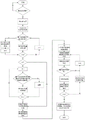
图1为本发明中基于PMU量测的面向主动配电网的网络分区方法流程图;Fig. 1 is the flow chart of the network partitioning method for the active distribution network based on PMU measurement in the present invention;
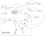
图2为本发明中以k个断路器为边界的典型区域的等效电路图。Fig. 2 is an equivalent circuit diagram of a typical area bounded by k circuit breakers in the present invention.
具体实施方式Detailed ways
本实施例中,一种基于PMU量测的面向主动配电网的网络分区方法,是应用于包含中央管理单元、PMU、区域控制单元所组成的主动配电网中;主动配电网中的每个微电网是以断路器为边界;且断路器与PMU相连;PMU还设置在可调度分布式发电设备和电网的连接点处;在每个微电网中设置有区域控制单元,用于监控分布式发电设备且在需要时断开负载。如图1所示,该网络分区方法是按如下步骤进行:In this embodiment, a network partition method for active distribution network based on PMU measurement is applied to an active distribution network composed of a central management unit, a PMU, and a regional control unit; Each microgrid is bounded by a circuit breaker; and the circuit breaker is connected to the PMU; the PMU is also set at the connection point between the dispatchable distributed power generation equipment and the grid; a regional control unit is set in each microgrid for monitoring Distribute generation equipment and disconnect loads when required. As shown in Figure 1, the network partition method is performed as follows:
步骤一、建立微电网集群的运行约束;
步骤1.1、利用式(1)建立负载-发电平衡约束:Step 1.1, use equation (1) to establish load-generation balance constraints:

式(1)中,PS,i,PW,i和PPV,i分别为第i个可调度分布式发电设备、风力发电设备和光伏发电设备的输出功率,1≤i≤I,I为分布式发电设备总数;第m个区域内总分布式发电设备功率
表1.微电网集群的运行约束表Table 1. Operation constraint table of microgrid cluster

步骤1.2、利用式(2)建立分布式发电设备的功率约束:Step 1.2, use formula (2) to establish the power constraints of distributed power generation equipment:
Pi min≤Pi(t)≤Pi max (2)P i min ≤ P i (t) ≤ P i max (2)
式(2)中,Pi min和Pi max分别是第i个分布式发电设备的最低和最高发电限制;Pi(t)是第i个分布式发电设备的功率;本实施例中,Pi min=5kW,Pi max=6000kW。In formula (2), P i min and P i max are the minimum and maximum power generation limits of the i-th distributed power generation equipment respectively; P i (t) is the power of the i-th distributed power generation equipment; in this embodiment, P i min =5 kW, P i max =6000 kW.
步骤1.3、利用式(3)建立第i个可调度分布式发电设备的功率约束:Step 1.3, use formula (3) to establish the power constraint of the i-th dispatchable distributed generation equipment:

步骤二、故障定位;Step 2, fault location;
主动配电网在发生故障且相关断路器运行之后形成孤岛区域,中央管理单元利用故障定位器算法确定位于孤岛区域内部的微电网;The active distribution network forms an island area after a fault occurs and the relevant circuit breaker operates, and the central management unit uses the fault locator algorithm to determine the microgrid located inside the island area;
步骤三、形成基本微电网;
步骤3.1、将孤岛区域中满足步骤一中所有约束的微电网作为基本微电网;Step 3.1. Use the microgrid in the island area that satisfies all the constraints in
步骤3.2、若孤岛区域中的某个微电网不能满足步骤一中的任意约束,则将其与相邻的基本微电网内进行组合,并评估组合后的微电网集群是否能满足步骤一中的所有约束;若能,则将组合后的微电网集群作为基本微电网;否则,利用局部减载逻辑对自身微电网内的负载按照事先确定的负载优先级进行减载,从而满足步骤一中的所有约束;Step 3.2. If a microgrid in the island area cannot satisfy any constraint in
步骤四、计算基本微电网的等效电路;Step 4. Calculate the equivalent circuit of the basic microgrid;
中央管理单元从安装在基本微电网边界处的PMU接收电压同步相量和电流同步相量,并将每个基本微电网用一个等效电路代替,如图2所示,等效电路包括:一个电压源和多个R-L分支,且每个主分支的阻抗相同;计算每个基本微电网的等效电路;The central management unit receives voltage synchrophasors and current synchrophasors from the PMU installed at the boundary of the basic microgrid, and replaces each basic microgrid with an equivalent circuit, as shown in Figure 2. The equivalent circuit includes: a A voltage source and multiple R-L branches with the same impedance for each main branch; calculate the equivalent circuit for each basic microgrid;
步骤4.1、利用式(5)计算主分支的阻抗Ru+jXu:Step 4.1, use formula (5) to calculate the impedance R u +jX u of the main branch:

式(5)中,u表示相位a、b、c,j表示虚部单位,

步骤4.2、利用式(6)计算电压源相量Eu∠δu:Step 4.2, use formula (6) to calculate the voltage source phasor E u ∠δ u :

步骤4.3、利用式(7)计算其他分支的阻抗:Step 4.3, using formula (7) to calculate the impedance of other branches:

步骤五、确定候选微电网集群;Step five, determine candidate microgrid clusters;
步骤5.1、确定基本微电网合并后仍然能满足步骤一中所有约束的所有可能组合,并将每种可能组合作为候选微电网集群;Step 5.1. Determine all possible combinations that can still satisfy all the constraints in
步骤5.2、若候选微电网集群中包含两个或两个以上的基本微电网,且至少存在一个减载过的基本微电网,则对相应候选微电网集群评估是否能重新连接脱落负载;若能,则相应候选微电网集群的区域控制单元重新调度相应的可调度分布式发电设备,用于重新连接所脱落的负载;Step 5.2. If the candidate microgrid cluster contains two or more basic microgrids, and there is at least one load-shedding basic microgrid, evaluate whether the corresponding candidate microgrid cluster can reconnect the dropped load; if it can , then the regional control unit of the corresponding candidate microgrid cluster reschedules the corresponding schedulable distributed generation equipment to reconnect the dropped load;
步骤5.3、对每个候选微电网集群用一个1×n维的标识向量进行标识,标识向量包含基本微电网之间的断路器状态的信息;标识向量中,以“1”标识关闭状态的断路器,以“0”标识打开状态的断路器;n表示断路器的数量;Step 5.3: Identify each candidate microgrid cluster with a 1×n-dimensional identification vector, the identification vector contains the information of the state of the circuit breaker between the basic microgrids; in the identification vector, "1" is used to identify the circuit breaker in the closed state The open circuit breaker is marked with "0"; n represents the number of circuit breakers;
步骤六、计算运行因子;Step 6. Calculating the operating factor;
使用基本微电网的等效电路,对步骤五得到的候选微电网集群集计算其运行因子;Using the equivalent circuit of the basic microgrid, calculate its operating factor for the candidate microgrid cluster set obtained in step 5;
步骤6.1、利用式(8)计算每个候选微电网集群总功率损耗F1,j:Step 6.1, use formula (8) to calculate the total power loss F 1,j of each candidate microgrid cluster:

式(8)中,Nj是组成第j个集群的微电网数量;本实施例中,j=1,2,…,10,F1,j、Nj查表2可得;In formula (8), N j is the number of microgrids forming the j-th cluster; in this embodiment, j=1,2,...,10, F 1,j and N j can be obtained from Table 2;
表2.各候选微电网集群目标函数参数表Table 2. Parameter table of each candidate microgrid cluster objective function

步骤6.2、利用式(9)计算所有候选微电网集群区域边界处的电压偏差之和F2,j:Step 6.2, using formula (9) to calculate the sum of voltage deviations F 2,j at the borders of all candidate microgrid clusters:

式(9)中,Vk是孤岛区域内第k个断路器连接到的总线的电压幅度,Vn是孤岛区域内任一断路器连接的总线的标称电压,K是孤岛区域内断路器的数量,K=10;F2,j查表2可得;In formula (9), V k is the voltage amplitude of the bus connected to the kth circuit breaker in the island area, V n is the nominal voltage of the bus connected to any circuit breaker in the island area, and K is the circuit breaker in the island area The quantity, K=10; F 2,j can be obtained by looking up Table 2;
步骤6.3、利用式(10)计算断开负载的总功率F3,j:Step 6.3, use formula (10) to calculate the total power F 3,j of disconnected load:

式(10)中,PDis,l是第l个微电网内部被断开负载的功率;F3,j查表2可得;In formula (10), P Dis,l is the power of the disconnected load inside the lth microgrid; F 3,j can be obtained by looking up Table 2;
步骤七、确定最佳候选微电网集群;Step 7. Determine the best candidate microgrid cluster;
步骤7.1、利用式(4)计算第j个候选微电网集群的目标函数

式(4)中,F1,j是第j个候选微电网集群的总功率损耗,F2,j是第j个候选微电网集群边界处的电压偏差之和,F3,j是第j个候选微电网集群中断开负载的总功率,α1、α2、α3分别是F1,j、F2,j、F3,j的权重;本实施例中,α1=α2=α3=1;Fm查表2可得;In formula (4), F 1,j is the total power loss of the jth candidate microgrid cluster, F 2,j is the sum of the voltage deviation at the boundary of the jth candidate microgrid cluster, F 3,j is the jth candidate microgrid cluster α 1 , α 2 , and α 3 are the weights of F 1,j , F 2,j , and F 3,j respectively; in this embodiment, α 1 =α 2 =α 3 =1; F m can be obtained from table 2;
步骤7.2、中央管理单元根据最佳微电网集群的标识向量,将相应的通断命令发送给相应的断路器,以在孤岛区域内形成最佳微电网集群。Step 7.2, the central management unit sends the corresponding on-off command to the corresponding circuit breaker according to the identification vector of the optimal micro-grid cluster, so as to form the optimal micro-grid cluster in the island area.
本实施例中,由表2可得,若综合考虑三个运行因子,由最小目标函数值可知,候选微电网集群1是电网分区的最佳选择;若只考虑使微电网集群总功率损耗最小,应选择候选微电网集群1或候选微电网集群5;若只考虑使候选微电网集群区域边界处的电压偏差之和最小,应选择候选微电网集群6。In this embodiment, it can be obtained from Table 2 that if the three operating factors are comprehensively considered, it can be known from the minimum objective function value that the
Claims (3)


Priority Applications (1)
| Application Number | Priority Date | Filing Date | Title |
|---|---|---|---|
| CN202011598802.9A CN112531663B (en) | 2020-12-30 | 2020-12-30 | A network partition method for active distribution network based on PMU measurement |
Applications Claiming Priority (1)
| Application Number | Priority Date | Filing Date | Title |
|---|---|---|---|
| CN202011598802.9A CN112531663B (en) | 2020-12-30 | 2020-12-30 | A network partition method for active distribution network based on PMU measurement |
Publications (2)
| Publication Number | Publication Date |
|---|---|
| CN112531663A CN112531663A (en) | 2021-03-19 |
| CN112531663B true CN112531663B (en) | 2023-02-28 |
Family
ID=74977080
Family Applications (1)
| Application Number | Title | Priority Date | Filing Date |
|---|---|---|---|
| CN202011598802.9A Active CN112531663B (en) | 2020-12-30 | 2020-12-30 | A network partition method for active distribution network based on PMU measurement |
Country Status (1)
| Country | Link |
|---|---|
| CN (1) | CN112531663B (en) |
Families Citing this family (4)
| Publication number | Priority date | Publication date | Assignee | Title |
|---|---|---|---|---|
| CN113341275B (en) * | 2021-06-10 | 2023-03-14 | 西安理工大学 | Method for positioning single-phase earth fault of power distribution network |
| CN115085288B (en) * | 2022-07-18 | 2026-01-13 | 国网上海市电力公司 | Power optimization distribution control method for fixed-frequency island micro-grid |
| CN119065227B (en) * | 2024-10-25 | 2025-03-21 | 浙江简捷物联科技有限公司 | Fault monitoring and handling methods for EMS management system |
| CN121097709B (en) * | 2025-11-04 | 2026-02-10 | 国网四川省电力公司天府新区供电公司 | Multi-micro-grid energy management method, device, equipment and medium |
Citations (5)
| Publication number | Priority date | Publication date | Assignee | Title |
|---|---|---|---|---|
| CN105474493A (en) * | 2013-08-23 | 2016-04-06 | Abb研究有限公司 | Adaptive protection for distribution grids based on zone concept |
| CN106981875A (en) * | 2017-04-26 | 2017-07-25 | 国网江西省电力公司电力科学研究院 | The restoration methods of distribution network failure containing DG of meter and plan isolated island |
| CN108711882A (en) * | 2018-07-19 | 2018-10-26 | 国网山东省电力公司青岛供电公司 | Active distribution network isolated island division methods containing distributed generation resource and micro-capacitance sensor |
| CN108988322A (en) * | 2018-06-30 | 2018-12-11 | 南京理工大学 | The microgrid optimization of operation strategy method of consideration system time variation |
| EP3700040A1 (en) * | 2019-02-22 | 2020-08-26 | ABB Schweiz AG | Method of controlling a power distribution system including a microgrid |
Family Cites Families (1)
| Publication number | Priority date | Publication date | Assignee | Title |
|---|---|---|---|---|
| WO2015048737A1 (en) * | 2013-09-30 | 2015-04-02 | Do Rosario Jackseario Antonio Dionisio | Power quality of service optimization for microgrids |
-
2020
- 2020-12-30 CN CN202011598802.9A patent/CN112531663B/en active Active
Patent Citations (5)
| Publication number | Priority date | Publication date | Assignee | Title |
|---|---|---|---|---|
| CN105474493A (en) * | 2013-08-23 | 2016-04-06 | Abb研究有限公司 | Adaptive protection for distribution grids based on zone concept |
| CN106981875A (en) * | 2017-04-26 | 2017-07-25 | 国网江西省电力公司电力科学研究院 | The restoration methods of distribution network failure containing DG of meter and plan isolated island |
| CN108988322A (en) * | 2018-06-30 | 2018-12-11 | 南京理工大学 | The microgrid optimization of operation strategy method of consideration system time variation |
| CN108711882A (en) * | 2018-07-19 | 2018-10-26 | 国网山东省电力公司青岛供电公司 | Active distribution network isolated island division methods containing distributed generation resource and micro-capacitance sensor |
| EP3700040A1 (en) * | 2019-02-22 | 2020-08-26 | ABB Schweiz AG | Method of controlling a power distribution system including a microgrid |
Also Published As
| Publication number | Publication date |
|---|---|
| CN112531663A (en) | 2021-03-19 |
Similar Documents
| Publication | Publication Date | Title |
|---|---|---|
| CN112531663B (en) | A network partition method for active distribution network based on PMU measurement | |
| CN110011422A (en) | Intelligent power distribution operation monitoring system and regulation method based on artificial neural network | |
| Jia et al. | Analysis of the transition between multiple operational modes for hybrid AC/DC microgrids | |
| CN106549380A (en) | Multi-modal microgrid energy coordinating and optimizing control method | |
| CN118826001B (en) | A regional autonomous hierarchical control method for active distribution network based on master station system | |
| WO2013079360A2 (en) | Controlling an electrical grid with islanded operation | |
| CN115423242A (en) | Power supply capacity mining method based on power distribution network reconstruction | |
| CN117477609A (en) | Energy management system and method for hydrogen-electricity coupling system in park | |
| CN110380398A (en) | A kind of direct-current grid power distribution method and system | |
| CN120855544A (en) | AC/DC hybrid microgrid control system based on DC-flexible substation | |
| Zhang et al. | Multi–objective cluster partition method for distribution network considering uncertainties of distributed generations and loads | |
| CN108233361B (en) | Hierarchical and partitioned collaborative control method for integrated energy supply system for campus microgrid | |
| CN115714394A (en) | Coordinated control method, system, equipment and medium for different time scales of microgrid | |
| Xu et al. | Optimal sizing of small hydro power plants in consideration of voltage control | |
| Li et al. | Adaptive coordinated control of microgrid under communication interruption scenario | |
| Gao et al. | Distributed coordinated management for multiple distributed energy resources optimal operation with security constrains | |
| Mi et al. | Adaptive power allocation strategy for isolated DC microgrid with unmatched line impedance and abnormal communication | |
| Wang et al. | Energy management system for multi-microgrid | |
| Zhang et al. | Coordinated control of energy storage devices and photovoltaic inverters for voltage regulation based on multi-agent system | |
| Zhou et al. | Research on multi-objective optimal dispatching and low voltage of distributed generation in rural distribution network | |
| Lei et al. | Rooted tree based searching strategies for intentional islanding of distributed generation | |
| Wu et al. | Service restoration of active distribution network considering the islanded operation of distributed generation and micro-grid | |
| Yan et al. | Distribution network reconfiguration with improved multi-objective particle swarm optimization algorithm | |
| Yang et al. | Power coordinated control of the islanded multi-layer microgrids | |
| Lu et al. | Control method and protection design for multi-station parallel operation of island microgrid system |
Legal Events
| Date | Code | Title | Description |
|---|---|---|---|
| PB01 | Publication | ||
| PB01 | Publication | ||
| SE01 | Entry into force of request for substantive examination | ||
| SE01 | Entry into force of request for substantive examination | ||
| GR01 | Patent grant | ||
| GR01 | Patent grant |