EP3699797B1 - Data processing method and device, and computer apparatus - Google Patents
Data processing method and device, and computer apparatus Download PDFInfo
- Publication number
- EP3699797B1 EP3699797B1 EP18868645.5A EP18868645A EP3699797B1 EP 3699797 B1 EP3699797 B1 EP 3699797B1 EP 18868645 A EP18868645 A EP 18868645A EP 3699797 B1 EP3699797 B1 EP 3699797B1
- Authority
- EP
- European Patent Office
- Prior art keywords
- data
- maintenance
- communication process
- logic computation
- internal communication
- Prior art date
- Legal status (The legal status is an assumption and is not a legal conclusion. Google has not performed a legal analysis and makes no representation as to the accuracy of the status listed.)
- Active
Links
Images




Classifications
-
- G—PHYSICS
- G06—COMPUTING OR CALCULATING; COUNTING
- G06F—ELECTRIC DIGITAL DATA PROCESSING
- G06F21/00—Security arrangements for protecting computers, components thereof, programs or data against unauthorised activity
- G06F21/50—Monitoring users, programs or devices to maintain the integrity of platforms, e.g. of processors, firmware or operating systems
- G06F21/57—Certifying or maintaining trusted computer platforms, e.g. secure boots or power-downs, version controls, system software checks, secure updates or assessing vulnerabilities
-
- G—PHYSICS
- G06—COMPUTING OR CALCULATING; COUNTING
- G06F—ELECTRIC DIGITAL DATA PROCESSING
- G06F21/00—Security arrangements for protecting computers, components thereof, programs or data against unauthorised activity
- G06F21/50—Monitoring users, programs or devices to maintain the integrity of platforms, e.g. of processors, firmware or operating systems
- G06F21/57—Certifying or maintaining trusted computer platforms, e.g. secure boots or power-downs, version controls, system software checks, secure updates or assessing vulnerabilities
- G06F21/577—Assessing vulnerabilities and evaluating computer system security
-
- G—PHYSICS
- G06—COMPUTING OR CALCULATING; COUNTING
- G06F—ELECTRIC DIGITAL DATA PROCESSING
- G06F11/00—Error detection; Error correction; Monitoring
- G06F11/07—Responding to the occurrence of a fault, e.g. fault tolerance
- G06F11/16—Error detection or correction of the data by redundancy in hardware
- G06F11/20—Error detection or correction of the data by redundancy in hardware using active fault-masking, e.g. by switching out faulty elements or by switching in spare elements
- G06F11/202—Error detection or correction of the data by redundancy in hardware using active fault-masking, e.g. by switching out faulty elements or by switching in spare elements where processing functionality is redundant
-
- G—PHYSICS
- G06—COMPUTING OR CALCULATING; COUNTING
- G06F—ELECTRIC DIGITAL DATA PROCESSING
- G06F11/00—Error detection; Error correction; Monitoring
- G06F11/07—Responding to the occurrence of a fault, e.g. fault tolerance
- G06F11/16—Error detection or correction of the data by redundancy in hardware
- G06F11/20—Error detection or correction of the data by redundancy in hardware using active fault-masking, e.g. by switching out faulty elements or by switching in spare elements
- G06F11/2097—Error detection or correction of the data by redundancy in hardware using active fault-masking, e.g. by switching out faulty elements or by switching in spare elements maintaining the standby controller/processing unit updated
-
- G—PHYSICS
- G06—COMPUTING OR CALCULATING; COUNTING
- G06F—ELECTRIC DIGITAL DATA PROCESSING
- G06F9/00—Arrangements for program control, e.g. control units
- G06F9/06—Arrangements for program control, e.g. control units using stored programs, i.e. using an internal store of processing equipment to receive or retain programs
- G06F9/46—Multiprogramming arrangements
- G06F9/52—Program synchronisation; Mutual exclusion, e.g. by means of semaphores
-
- G—PHYSICS
- G06—COMPUTING OR CALCULATING; COUNTING
- G06F—ELECTRIC DIGITAL DATA PROCESSING
- G06F9/00—Arrangements for program control, e.g. control units
- G06F9/06—Arrangements for program control, e.g. control units using stored programs, i.e. using an internal store of processing equipment to receive or retain programs
- G06F9/46—Multiprogramming arrangements
- G06F9/54—Interprogram communication
- G06F9/542—Event management; Broadcasting; Multicasting; Notifications
-
- G—PHYSICS
- G06—COMPUTING OR CALCULATING; COUNTING
- G06F—ELECTRIC DIGITAL DATA PROCESSING
- G06F9/00—Arrangements for program control, e.g. control units
- G06F9/06—Arrangements for program control, e.g. control units using stored programs, i.e. using an internal store of processing equipment to receive or retain programs
- G06F9/46—Multiprogramming arrangements
- G06F9/54—Interprogram communication
- G06F9/543—User-generated data transfer, e.g. clipboards, dynamic data exchange [DDE], object linking and embedding [OLE]
-
- G—PHYSICS
- G06—COMPUTING OR CALCULATING; COUNTING
- G06F—ELECTRIC DIGITAL DATA PROCESSING
- G06F9/00—Arrangements for program control, e.g. control units
- G06F9/06—Arrangements for program control, e.g. control units using stored programs, i.e. using an internal store of processing equipment to receive or retain programs
- G06F9/46—Multiprogramming arrangements
- G06F9/54—Interprogram communication
- G06F9/544—Buffers; Shared memory; Pipes
Definitions
- the present invention relates to a field of communication, and more particularly, to a data processing method and a computer readable storage medium.
- a vital computer system consists of a vital computer and a non-vital computer; the vital computer deploys safety-related services, and the non-vital computer deploys non-safety-related services.
- a double 2-vote-2 vital computer architecture is mostly used, with double-set redundancy design, and both systems assuming safety functions.
- CHEN GUANGWU ET AL "Research and Implementation of Fault-Tolerant Computer Interlocking System” (COMPUTATIONAL INTELLIGENCE AND SOFTWARE ENGINEERING (CISE), 2010 INTERNATIONAL CONFERENCE ON, IEEE, PISCATAWAY, NJ, USA, 10 December 2010 (2010-12-10), pages 1 -4 ) discloses a computer interlocking system for railway stations.
- CN 105739299A discloses a control device based on double 2-vote-2 safety redundancy system.
- an objective of the present invention is to provide a data processing method and a computer readable storage medium, so as to solve at least one of problems as mentioned above.
- a data processing method is provided according to the claim 1, as well as some advantageous embodiments according to its dependent claims.
- a computer readable storage medium the computer readable storage medium storing the computer program executing the above-described method.
- an embodiment of the present invention provide a data processing solution, to meet a present situation of relatively high requirements on various items of performance of the current safety platform, so as to ensure safety of a vital computer system.
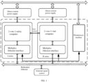
- FIG. 1 is a structural diagram of the vital computer system; and as shown in FIG. 1 , the system comprises: a I-series system, a II-series system, and a maintenance machine; each system includes a 2-vote-2 vital computer and a multiplex Ethernet interface, an external signal system communicates with the I-series system and the II-series system via redundant Ethernet, respectively, and the I-series system and the II-series system communicate with the maintenance machine via the multiplex Ethernet.
- FIG. 2 is a flow chart of the data processing method, and as shown in FIG. 2 , the method comprises:
- Step 201 receiving data from an internal communication process and performing a logic computation operation on the data, wherein, the logic computation operation includes a data synchronization comparison operation;
- Step 202 returning the data subjected to the logic computation operation to the internal communication process
- Step 203 transmitting maintenance data generated during the logic computation operation to a maintenance communication process.
- the safety data may be maintained synchronous, and by transmitting the maintenance data in the logic computation operation to the maintenance communication process, the system is monitored through the maintenance data, so as to improve safety of the vital computer system.
- the performing a logic computation operation on the data includes: performing intra-system and inter-system synchronization comparison operations on the data; encapsulating the data subjected to the synchronization comparison operation; and transmitting the encapsulated data on a predetermined channel.
- performing the synchronization comparison operation on the data data can be synchronized, so as to ensure that the two series of systems may be in a same working state.
- the internal communication process may further receive intra-system, inter-system and extra-system data, parse the intra-system, inter-system and extra-system data received by frames and layers, and transmit the data parsed by frames and layers on the predetermined channel. By transmitting the data on the predetermined channel, it is possible to further ensure safety of the data.
- the internal communication process After the data subjected to the logic computation operation is returned to the internal communication process, the internal communication process performs protocol encapsulation on the data according to an output data instruction and then transmits the same.
- the output data instruction When the output data instruction is conducting to transmit synchronous data or backup data to another system, the data to be transmitted is subjected to safety protocol encapsulation, and transmitted to a corresponding system according to the intranet data sub-contracting protocol.
- the data to be transmitted is acquired from the stored data cache, and transmitted to a predetermined storage device according to a data sub-contracting protocol.
- the vital computer system shown in FIG. 1 may use a VxWorks operating system, the vital computer system provides a set of data safety business function framework for application software, the application software is based on the vital computer system framework, and is capable of implementing data safety comparison and redundant processing, which can meet high safety requirements of the system, and high availability required by a signal system.
- a bottom layer of the vital computer system framework is an operating system interface adaptation layer; with the VxWorks operating system and its board support package (BSP) as underlying support, and by calling application programming interface (API) and BSP custom interface function of the operating system, it is possible to implement task scheduling, socket programming, interrupt management, and hardware-related driver functions.
- the system framework shields the application software from the operating system's API, so that the application software can implement independence and portability of the operating system.
- a task framework layer performs multitask partitioning on a system process, according to a timing requirement of the application software.
- a triggering condition for each task is singularized, and is coupled with other tasks through data only, which avoids control coupling or timing coupling.
- FIG. 3 is a working schematic diagram of a plurality of processes based on a VxWorks operating system; as shown in FIG. 3 , two-way communication is performed between the internal communication process and the logic computation process, one-way communication is performed between the logic computation process and the maintenance communication process, no direct communication is performed between the internal communication process and the maintenance communication process, and such a structure can improve safety of the vital computer.
- two-way communication is performed between the internal communication process and the logic computation process
- one-way communication is performed between the logic computation process and the maintenance communication process
- no direct communication is performed between the internal communication process and the maintenance communication process
- the input data is received from the internal communication process, the logic computation operation for all the input data is accomplished, and the generated output data is transmitted to the internal communication process.
- intermediate computation process data, system state data, and alarm data are transmitted to the maintenance communication process in a form of maintenance data.
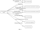
- FIG. 4 shows an operation completed by a logic computation thread within one cycle; as shown in FIG. 4 , the operation executed by the logic computation thread includes:
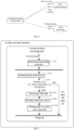
- FIG. 5 is a flow chart of the logic computation thread; and as shown in FIG. 5 , the logic computation thread includes:
- All inter-system communication of the vital computer is in a mode of Ethernet, which mainly accomplishes a copying function of communication data, the internal communication process maintains multiple socket links, internal interface is the logic computation process, and the external interface may be divided into two threads, which are respectively a communication data receiving thread and an output data thread, and corresponding physical interfaces include three categories below:
- the communication data receiving thread mainly accomplishes functions of internal data network monitoring and data receiving.
- the communication data receiving thread includes two tasks: a high-priority task and a low-priority task, wherein, the high-priority task monitors and receives synchronization channel data, and the low-priority task monitors and receives external communication channel and inter-system big data quantity channel data.
- the socket interface is called to receive the data, and accomplish parsing and grouping of the data packet.
- FIG. 6 is a schematic diagram of operation of the communication data receiving thread; and as shown in FIG. 6 , the communication data receiving thread includes:
- Data communication for accomplishing network monitoring, data receiving, data parsing by frames and layers and channel identifying;
- Fault processing for executing fault identification of the present task by setting/clearing a fault.
- FIG. 7 is a flow chart of the communication data receiving thread; and as shown in FIG. 7 , the communication data receiving thread includes:
- the output data thread waits for a data output event:
- data to be output is subjected to parity split according to CPU ID, and the split data is subjected to protocol encapsulation, and transmitted to an external communication device according to the intranet data sub-contracting protocol;
- the inter-system synchronization data event or a main system backup data transmission event When the inter-system synchronization data event or a main system backup data transmission event are received, the inter-system synchronization data is subjected to safety protocol encapsulation, and transmitted to other systems according to the intranet data sub-contracting protocol;
- data to be transmitted is acquired from a storage data cache and is transmitted to a storage device according to the data subcontracting protocol.
- FIG. 8 is an operation schematic diagram of the output data thread; and as shown in FIG. 8 , the output data thread includes:
- Data communication for executing data splitting, protocol encapsulating and data transmitting
- Data storage for acquiring storage data to execute data storage
- Fault processing for executing fault identification and processing of the present task by setting/clearing a fault.
- FIG. 9 is a flow chart of the output data thread; and as shown in FIG. 9 , the output data thread includes:
- the maintenance communication process is a one-way data forwarding channel, and is mainly responsible for forwarding the maintenance data generated by a logic processing process to a maintenance machine.
- the maintenance data is mainly intermediate computation process data, system state data, and alarm data, etc., generated during operation of the logic computation process, and is transmitted to the maintenance communication process by the logic computation process, so as to facilitate subsequent examination, and ensure safety of the system.
- the data processing method may implement safety redundancy management of the system data, provide safe and reliable data and communication channels for the application software, and implement monitoring and redundancy switching processing of the system state.
- an embodiment of the present invention further provides a data processing apparatus, which may implement the above-described method.
- FIG. 10 is a structural block diagram of a data processing apparatus according to the embodiment of the present invention. and as shown in FIG. 10 , the apparatus comprises: an internal communication unit 101, a logic computation unit 102, a logic computation data transmission unit 103 and a maintenance data transmission unit 104, wherein:
- the safety data may be maintained synchronous, and by transmitting the maintenance data in the logic computation operation to the maintenance communication process, it is possible to implement monitoring on the system through the maintenance data, so as to ensure safety of the vital computer system.
- the internal communication unit 101 includes:
- the logic computation unit 102 includes:
- the internal communication unit 101 further includes: a second encapsulated data transmission module (not shown in the diagram), configured to perform protocol encapsulation on the data according to an output data instruction and then transmit the same. Specifically, after the logic computation data transmission unit 103 returns the data subjected to the logic computation operation to the internal communication process, the second encapsulated data transmission module may perform protocol encapsulation on the data according to the specific output data instruction and then transmit the same.
- a second encapsulated data transmission module (not shown in the diagram), configured to perform protocol encapsulation on the data according to an output data instruction and then transmit the same.
- An embodiment of the present invention further provides a computer readable storage medium, the computer readable storage medium storing the computer program executing the above-described method.
- data safety redundancy management may be implemented, to provide the application software with safe and reliable data and communication channels, and implement state monitoring and redundancy switching processing on the system.
- the vital computer system may implement functions below:
- the system is capable of performing intra-system double-machine cross comparison on input and output data of the application software, executing safety processing when a comparison result show that they are inconsistent, performing double-machine interactive comparison on system operation state information, confirming that the two intra-system machines are in a same working state in real time; and at a same time, is capable of implementing process data cross comparison function of the application software, implementing real-time monitoring of the application software, and confirming that the double-machine application software keeps operating synchronously.
- the system is capable of implementing dual-system synchronization working management, executing consistency processing on the dual-system input and output data by dual-system data exchange; performing real-time interaction of the dual-system operation state, implementing a failover system function; and is also capable of providing process data inter-system interaction function of the application software.
- the intra-system and the inter-system vital computer implements IO data communication of the external communication device via the internal Ethernet communication network.
- the internal network is isolated from the external network, and ensures data safety by using a dedicated communication protocol.
- the system is capable of encapsulating underlying functions, providing call interfaces for operation software, and implementing execution of logical functions and data transmission.
- the system is capable of monitoring execution state of the operating software, finding abnormalities in real time, and executing safety processing.
- the system is capable of self-checking cyclically, promptly alarming when a fault is found, and executing fault safety processing.
- respective modules or respective steps according to the present invention as described above may be implemented by a general-purpose computer system, which can be centralized on a single computer, or distributed on a network formed by a plurality of computing apparatuses; alternatively, they can be implemented with computer apparatus executable program codes, so that they can be stored in a storage apparatus to be executed by a computing apparatus, or they can be implemented by respectively fabricating them into respective integrated circuit modules, or fabricating a plurality of modules or steps among them into a single integrated circuit module.
- the present invention is not limited to any specific combination of hardware and software.
Landscapes
- Engineering & Computer Science (AREA)
- Theoretical Computer Science (AREA)
- Software Systems (AREA)
- General Engineering & Computer Science (AREA)
- General Physics & Mathematics (AREA)
- Physics & Mathematics (AREA)
- Computer Hardware Design (AREA)
- Computer Security & Cryptography (AREA)
- Quality & Reliability (AREA)
- Computing Systems (AREA)
- Multimedia (AREA)
- Hardware Redundancy (AREA)
- Computer And Data Communications (AREA)
Description
- The present invention relates to a field of communication, and more particularly, to a data processing method and a computer readable storage medium.
- A vital computer system consists of a vital computer and a non-vital computer; the vital computer deploys safety-related services, and the non-vital computer deploys non-safety-related services. In an existing vital computer system, a double 2-vote-2 vital computer architecture is mostly used, with double-set redundancy design, and both systems assuming safety functions.
- With development of a railway signal technology, volume of business carried by a terrestrial signal system logic computation unit has become increasingly large and complex; a logic computation software platform needs to provide sufficient computing performance and data throughput capacity, which leads to extremely high requirements on various items of performance of the software platform; a current vital computer platform can no longer meet such requirements, and thus cannot guarantee safety of the vital computer system.
- CHEN GUANGWU ET AL: "Research and Implementation of Fault-Tolerant Computer Interlocking System" (COMPUTATIONAL INTELLIGENCE AND SOFTWARE ENGINEERING (CISE), 2010 INTERNATIONAL CONFERENCE ON, IEEE, PISCATAWAY, NJ, USA, 10 December 2010 (2010-12-10), pages 1 -4) discloses a computer interlocking system for railway stations.
CN 105739299A discloses a control device based on double 2-vote-2 safety redundancy system. - In view of this, an objective of the present invention is to provide a data processing method and a computer readable storage medium, so as to solve at least one of problems as mentioned above.
- According to one aspect of the present invention, a data processing method is provided according to the claim 1, as well as some advantageous embodiments according to its dependent claims.
- According to still another aspect of the present invention, there is provided a computer readable storage medium, the computer readable storage medium storing the computer program executing the above-described method.
- By the technical solution provided by the present invention, it is possible to improve safety of the vital computer system.
- Embodiments of the present invention are described with reference to accompanying drawings below, so that the above-described and other objectives, features and advantages of the present invention will be more apparent, in the drawings:
-
FIG. 1 is a structural diagram of a vital computer system; -
FIG. 2 is a flow chart of a data processing method according to an embodiment of the present invention; -
FIG. 3 is a working schematic diagram of a plurality of processes based on a VxWorks operating system according to an embodiment of the present invention; -
FIG. 4 is a working schematic diagram of a logic computation thread according to an embodiment of the present invention; -
FIG. 5 is a working flow chart of a logic computation thread according to an embodiment of the present invention; -
FIG. 6 is a working schematic diagram of a communication data receiving thread according to an embodiment of the present invention; -
FIG. 7 is a working flow chart of the communication data receiving thread according to the embodiment of the present invention; -
FIG. 8 is a working schematic diagram of an output data thread according to an embodiment of the present invention; -
FIG. 9 is a working flow chart of the output data thread according to the embodiment of the present invention; -
FIG. 10 is a structural block diagram of a data processing apparatus according to an embodiment of the present invention; -
FIG. 11 is a structural block diagram of aninternal communication unit 101 according to an embodiment of the present invention; -
FIG. 12 is a structural block diagram of alogic computation unit 102 according to an embodiment of the present invention. - Hereinafter, the present invention is described based embodiments; however, the present invention is not limited to these embodiments only.
- With increase of volume of business carried by a terrestrial signal system logic computation unit, requirements on various items of performance of a vital computer safety platform is also raised, a current safety platform can no longer meet such requirements, and therefore, an embodiment of the present invention provide a data processing solution, to meet a present situation of relatively high requirements on various items of performance of the current safety platform, so as to ensure safety of a vital computer system.
-
FIG. 1 is a structural diagram of the vital computer system; and as shown inFIG. 1 , the system comprises: a I-series system, a II-series system, and a maintenance machine; each system includes a 2-vote-2 vital computer and a multiplex Ethernet interface, an external signal system communicates with the I-series system and the II-series system via redundant Ethernet, respectively, and the I-series system and the II-series system communicate with the maintenance machine via the multiplex Ethernet. - Based on the system shown in
FIG. 1 , an embodiment of the present invention provides a data processing method.FIG. 2 is a flow chart of the data processing method, and as shown inFIG. 2 , the method comprises: - Step 201: receiving data from an internal communication process and performing a logic computation operation on the data, wherein, the logic computation operation includes a data synchronization comparison operation;
- Step 202: returning the data subjected to the logic computation operation to the internal communication process;
- Step 203: transmitting maintenance data generated during the logic computation operation to a maintenance communication process.
- By performing logic computation operation on the data of internal communication process and then returning to the internal communication process, the safety data may be maintained synchronous, and by transmitting the maintenance data in the logic computation operation to the maintenance communication process, the system is monitored through the maintenance data, so as to improve safety of the vital computer system.
- Specifically, the performing a logic computation operation on the data, includes: performing intra-system and inter-system synchronization comparison operations on the data; encapsulating the data subjected to the synchronization comparison operation; and transmitting the encapsulated data on a predetermined channel. By performing the synchronization comparison operation on the data, data can be synchronized, so as to ensure that the two series of systems may be in a same working state.
- Before
step 201, the internal communication process may further receive intra-system, inter-system and extra-system data, parse the intra-system, inter-system and extra-system data received by frames and layers, and transmit the data parsed by frames and layers on the predetermined channel. By transmitting the data on the predetermined channel, it is possible to further ensure safety of the data. - After the data subjected to the logic computation operation is returned to the internal communication process, the internal communication process performs protocol encapsulation on the data according to an output data instruction and then transmits the same.
- When the output data instruction is outputting data outside of the system, a split operation is performed on the data to be output, the split data is subjected to protocol encapsulation, and transmitted outside of the system according to an intranet data sub-contracting protocol.
- When the output data instruction is conducting to transmit synchronous data or backup data to another system, the data to be transmitted is subjected to safety protocol encapsulation, and transmitted to a corresponding system according to the intranet data sub-contracting protocol.
- When the output data instruction is conducting to transmit stored data, the data to be transmitted is acquired from the stored data cache, and transmitted to a predetermined storage device according to a data sub-contracting protocol.
- In order to further understand the embodiment of the present invention, the embodiment of the present invention is described in detail below based on the system shown in
FIG. 1 . - In an actual operation, the vital computer system shown in
FIG. 1 may use a VxWorks operating system, the vital computer system provides a set of data safety business function framework for application software, the application software is based on the vital computer system framework, and is capable of implementing data safety comparison and redundant processing, which can meet high safety requirements of the system, and high availability required by a signal system. - A bottom layer of the vital computer system framework is an operating system interface adaptation layer; with the VxWorks operating system and its board support package (BSP) as underlying support, and by calling application programming interface (API) and BSP custom interface function of the operating system, it is possible to implement task scheduling, socket programming, interrupt management, and hardware-related driver functions. At a same time, the system framework shields the application software from the operating system's API, so that the application software can implement independence and portability of the operating system.
- A task framework layer performs multitask partitioning on a system process, according to a timing requirement of the application software. A triggering condition for each task is singularized, and is coupled with other tasks through data only, which avoids control coupling or timing coupling.
-
FIG. 3 is a working schematic diagram of a plurality of processes based on a VxWorks operating system; as shown inFIG. 3 , two-way communication is performed between the internal communication process and the logic computation process, one-way communication is performed between the logic computation process and the maintenance communication process, no direct communication is performed between the internal communication process and the maintenance communication process, and such a structure can improve safety of the vital computer. Hereinafter, the three processes are described in detail below in conjunction withFIG. 3 . - The input data is received from the internal communication process, the logic computation operation for all the input data is accomplished, and the generated output data is transmitted to the internal communication process. At a same time, according to requirements of specific applications, intermediate computation process data, system state data, and alarm data are transmitted to the maintenance communication process in a form of maintenance data.
- Within a synchronization cycle, the logic computation thread needs to accomplish intra-system and inter-system data synchronization comparison, time synchronization and real-time adjustment of a control mode within the present cycle.
FIG. 4 shows an operation completed by a logic computation thread within one cycle; as shown inFIG. 4 , the operation executed by the logic computation thread includes: - Data communication, for encapsulating, transmitting and parsing internal synchronization data, and performing channel identification;
- Intra-system data synchronization comparison operation, for performing cyclic data intra-system synchronization comparison by data item setting and data item synchronization comparison;
- Inter-system data synchronization comparison operation, for performing cyclic data inter-system synchronization comparison by data item setting and data item synchronization comparison;
- Time synchronization operation, for performing cyclic intra-system and inter-system CPU module time synchronization and local timestamp refresh according to timestamp adjustment;
- Control mode management, for performing adjustment strategy and refreshing of a dual-system control mode by adjusting control mode in real time;
- Fault processing, for executing fault identification and processing of each synchronization cycle by setting/clearing a fault.
-
FIG. 5 is a flow chart of the logic computation thread; and as shown inFIG. 5 , the logic computation thread includes: - Step 501: transmitting inter-system data;
- Step 502: transmitting inter-CPU data;
- Step 503: receiving and parsing the inter-system data;
- Step 504: receiving and parsing the inter-CPU data;
- Step 505: synchronizing and comparing the inter-system data;
- Step 506: comparing the inter-system data;
- Step 507: adjusting the timestamp;
- Step 508: refreshing the control mode;
- Step 509: arranging IO data;
- Step 510: judging whether or not an application cycle is reached, if yes, executing
step 511; otherwise, the application cycle being not reached and ending the process; - Step 511: triggering an application management task.
- All inter-system communication of the vital computer is in a mode of Ethernet, which mainly accomplishes a copying function of communication data, the internal communication process maintains multiple socket links, internal interface is the logic computation process, and the external interface may be divided into two threads, which are respectively a communication data receiving thread and an output data thread, and corresponding physical interfaces include three categories below:
- CPU on an opposite side of the present system, as a port for transmitting the intra-system data;
- CPU3, and Ethernet expansion board, for transmitting external communication data;
- CPU on a same side of an opposite system, for transmitting the inter-system data.
- Hereinafter, the communication data receiving thread and the output data thread are respectively described in detail.
- The communication data receiving thread mainly accomplishes functions of internal data network monitoring and data receiving. In an actual operation, the communication data receiving thread includes two tasks: a high-priority task and a low-priority task, wherein, the high-priority task monitors and receives synchronization channel data, and the low-priority task monitors and receives external communication channel and inter-system big data quantity channel data. When there is data on a network port, the socket interface is called to receive the data, and accomplish parsing and grouping of the data packet.
-
FIG. 6 is a schematic diagram of operation of the communication data receiving thread; and as shown inFIG. 6 , the communication data receiving thread includes: - Data communication, for accomplishing network monitoring, data receiving, data parsing by frames and layers and channel identifying;
- Fault processing, for executing fault identification of the present task by setting/clearing a fault.
-
FIG. 7 is a flow chart of the communication data receiving thread; and as shown inFIG. 7 , the communication data receiving thread includes: - Step 701: initializing monitoring socket fd (a socket file descriptor);
- Step 702: monitoring the network port;
- Step 703: judging whether or not there is data in the network port, if yes, executing
step 704, and if there is no data till timeout, ending the flow; - Step 704: receiving UDP data;
- Step 705: parsing FrameLayer;
- Step 706: writing data in a safety layer data field.
- The output data thread waits for a data output event:
- When an output external communication data event is received, data to be output is subjected to parity split according to CPU ID, and the split data is subjected to protocol encapsulation, and transmitted to an external communication device according to the intranet data sub-contracting protocol;
- When the inter-system synchronization data event or a main system backup data transmission event are received, the inter-system synchronization data is subjected to safety protocol encapsulation, and transmitted to other systems according to the intranet data sub-contracting protocol;
- When the storage data transmission event is received, data to be transmitted is acquired from a storage data cache and is transmitted to a storage device according to the data subcontracting protocol.
-
FIG. 8 is an operation schematic diagram of the output data thread; and as shown inFIG. 8 , the output data thread includes: - Data communication, for executing data splitting, protocol encapsulating and data transmitting;
- Data storage, for acquiring storage data to execute data storage;
- Fault processing, for executing fault identification and processing of the present task by setting/clearing a fault.
-
FIG. 9 is a flow chart of the output data thread; and as shown inFIG. 9 , the output data thread includes: - Executing step 901, when it is the outward communication data output event;
- Step 901: splitting the data, then executing step 902;
- Executing step 902: when it is the event of transmitting the synchronization data to other systems;
- Step 902: performing safety protocol encapsulation on the data, and then executing step 903;
- Step 903: transmitting the data by frames, and then ending the flow;
- Executing
step 904, when it is a storage data transmission event; - Step 904: generating a storage data packet;
- Step 905: executing storage data transmission, and then ending the flow.
- The maintenance communication process is a one-way data forwarding channel, and is mainly responsible for forwarding the maintenance data generated by a logic processing process to a maintenance machine. Here, the maintenance data is mainly intermediate computation process data, system state data, and alarm data, etc., generated during operation of the logic computation process, and is transmitted to the maintenance communication process by the logic computation process, so as to facilitate subsequent examination, and ensure safety of the system.
- The data processing method according to the embodiment of the present invention may implement safety redundancy management of the system data, provide safe and reliable data and communication channels for the application software, and implement monitoring and redundancy switching processing of the system state.
- Based on a similar inventive concept, an embodiment of the present invention further provides a data processing apparatus, which may implement the above-described method.
-
FIG. 10 is a structural block diagram of a data processing apparatus according to the embodiment of the present invention; and as shown inFIG. 10 , the apparatus comprises: aninternal communication unit 101, alogic computation unit 102, a logic computationdata transmission unit 103 and a maintenancedata transmission unit 104, wherein: - The
logic computation unit 102, configured to receive data from an internal communication process and perform a logic computation operation on the data, wherein, the logic computation operation includes a data synchronization comparison operation; - The logic computation
data transmission unit 103, configured to return the data subjected to the logic computation operation to the internal communication process; - The maintenance
data transmission unit 104, configured to transmit maintenance data generated during the logic computation operation to a maintenance communication process. - By performing the logic computation operation on the data of the internal communication process and then returning to the internal communication process, the safety data may be maintained synchronous, and by transmitting the maintenance data in the logic computation operation to the maintenance communication process, it is possible to implement monitoring on the system through the maintenance data, so as to ensure safety of the vital computer system.
- Specifically, as shown in
FIG. 11 , theinternal communication unit 101 includes: - A
data receiving module 1011, configured to receive intra-system, inter-system and extra-system data; - A
data parsing module 1012, configured to parse the data received by thedata receiving module 1011 by frames and layers; - A parsed
data transmission module 1013, configured to transmit the data parsed by frames and layers to thelogic computation unit 102 on a predetermined channel. - As shown in
FIG. 12 , thelogic computation unit 102 includes: - A
synchronization comparison module 1021, configured to perform intra-system and inter-system synchronization comparison operation on the received data; - A
data encapsulation module 1022, configured to encapsulate the data subjected to the synchronization comparison operation; - A first encapsulated
data transmission module 1023, configured to transmit the encapsulated data on the predetermined channel. - The
internal communication unit 101 further includes: a second encapsulated data transmission module (not shown in the diagram), configured to perform protocol encapsulation on the data according to an output data instruction and then transmit the same. Specifically, after the logic computationdata transmission unit 103 returns the data subjected to the logic computation operation to the internal communication process, the second encapsulated data transmission module may perform protocol encapsulation on the data according to the specific output data instruction and then transmit the same. - Since a principle for the apparatus to solve the problem is similar to that of the data processing method, for implementation of the apparatus, implementation of the data processing method may be referred to, and repeated parts will not be described.
- An embodiment of the present invention further provides a computer readable storage medium, the computer readable storage medium storing the computer program executing the above-described method.
- In summary, by the embodiments of the present invention, data safety redundancy management may be implemented, to provide the application software with safe and reliable data and communication channels, and implement state monitoring and redundancy switching processing on the system. Specifically, the vital computer system according to the embodiments of the present invention may implement functions below:
- The system is capable of performing intra-system double-machine cross comparison on input and output data of the application software, executing safety processing when a comparison result show that they are inconsistent, performing double-machine interactive comparison on system operation state information, confirming that the two intra-system machines are in a same working state in real time; and at a same time, is capable of implementing process data cross comparison function of the application software, implementing real-time monitoring of the application software, and confirming that the double-machine application software keeps operating synchronously.
- The system is capable of implementing dual-system synchronization working management, executing consistency processing on the dual-system input and output data by dual-system data exchange; performing real-time interaction of the dual-system operation state, implementing a failover system function; and is also capable of providing process data inter-system interaction function of the application software.
- The intra-system and the inter-system vital computer implements IO data communication of the external communication device via the internal Ethernet communication network. The internal network is isolated from the external network, and ensures data safety by using a dedicated communication protocol.
- The system is capable of encapsulating underlying functions, providing call interfaces for operation software, and implementing execution of logical functions and data transmission.
- The system is capable of monitoring execution state of the operating software, finding abnormalities in real time, and executing safety processing.
- The system is capable of self-checking cyclically, promptly alarming when a fault is found, and executing fault safety processing.
- Obviously, those skilled in the art should understand that, respective modules or respective steps according to the present invention as described above may be implemented by a general-purpose computer system, which can be centralized on a single computer, or distributed on a network formed by a plurality of computing apparatuses; alternatively, they can be implemented with computer apparatus executable program codes, so that they can be stored in a storage apparatus to be executed by a computing apparatus, or they can be implemented by respectively fabricating them into respective integrated circuit modules, or fabricating a plurality of modules or steps among them into a single integrated circuit module. Thus, the present invention is not limited to any specific combination of hardware and software.
- The above are only preferred embodiments of the present invention, but are not used for limiting the present invention; for those skilled in the art, various alternations and modifications may be made to the present invention.
Claims (3)
- A data processing method implemented by a vital computer system, the vital computer system including a I-series system, a II-series system, and a maintenance machine, each of the I-series and II-series system comprising a 2-vote-2 vital computer and a multiplex Ethernet interface, wherein
the method comprises:in a logic computation process, receiving input data from an internal communication process, and performing a logic computation operation on the input data and generating output data, wherein, the logic computation operation includes a data synchronization comparison operation;transmitting the output data generated by the logic computation operation to the internal communication process, wherein two-way communication is performed between the internal communication process and the logic computation process,in the internal communication process, performing protocol encapsulation on the output data according to an output data instruction and then transmitting the encapsulated data outside of the vital computer system; the method further comprising:transmitting maintenance data generated during the logic computation operation to a maintenance communication process, wherein the maintenance data includes intermediate computation process data, wherein the maintenance communication process is a one-way data forwarding channel, and is responsible for forwarding the maintenance data generated by a logic processing process to the maintenance machine, wherein one-way communication is performed between the logic computation process and the maintenance communication process, and no direct communication is performed between the internal communication process and the maintenance communication process,monitoring the vital computer system through the maintenance data, so as to ensure safety of the vital computer system. - The method according to claim 1, wherein, before receiving input data from an internal communication process, the method further comprises:the internal communication process receiving intra-system, inter-system and extra-system data;parsing the intra-system, inter-system and extra-system data received by frames and layers;transmitting the data parsed by frames and layers on the predetermined channel.
- A computer readable storage medium, wherein, the computer readable storage medium stores a
computer program executing the method according to any one of claims 1 to 2.
Priority Applications (1)
| Application Number | Priority Date | Filing Date | Title |
|---|---|---|---|
| RS20241224A RS66147B1 (en) | 2017-10-18 | 2018-05-09 | Data processing method and device, and computer apparatus |
Applications Claiming Priority (2)
| Application Number | Priority Date | Filing Date | Title |
|---|---|---|---|
| CN201710972563.0A CN107992752B (en) | 2017-10-18 | 2017-10-18 | Data processing method and device and computer equipment |
| PCT/CN2018/086114 WO2019076035A1 (en) | 2017-10-18 | 2018-05-09 | Data processing method and device, and computer apparatus |
Publications (4)
| Publication Number | Publication Date |
|---|---|
| EP3699797A1 EP3699797A1 (en) | 2020-08-26 |
| EP3699797A4 EP3699797A4 (en) | 2020-12-09 |
| EP3699797C0 EP3699797C0 (en) | 2024-08-28 |
| EP3699797B1 true EP3699797B1 (en) | 2024-08-28 |
Family
ID=62029839
Family Applications (1)
| Application Number | Title | Priority Date | Filing Date |
|---|---|---|---|
| EP18868645.5A Active EP3699797B1 (en) | 2017-10-18 | 2018-05-09 | Data processing method and device, and computer apparatus |
Country Status (5)
| Country | Link |
|---|---|
| EP (1) | EP3699797B1 (en) |
| CN (1) | CN107992752B (en) |
| HU (1) | HUE068892T2 (en) |
| RS (1) | RS66147B1 (en) |
| WO (1) | WO2019076035A1 (en) |
Families Citing this family (3)
| Publication number | Priority date | Publication date | Assignee | Title |
|---|---|---|---|---|
| CN107992752B (en) * | 2017-10-18 | 2020-05-22 | 北京全路通信信号研究设计院集团有限公司 | Data processing method and device and computer equipment |
| CN108877175A (en) * | 2018-06-27 | 2018-11-23 | 深圳市科陆电子科技股份有限公司 | A kind of system and its communication means converting Data Over Cable transmission to wireless transmission |
| CN114237855B (en) * | 2021-12-22 | 2025-03-04 | 卡斯柯信号有限公司 | A file storage method |
Family Cites Families (11)
| Publication number | Priority date | Publication date | Assignee | Title |
|---|---|---|---|---|
| KR100979096B1 (en) * | 2007-12-13 | 2010-09-02 | 주식회사 한화건설 | Optimal Operation Control System and Method for Membrane Separation Process Using Intermittent Aeration Air Cleaning Method |
| CN101605151B (en) * | 2009-07-10 | 2012-05-30 | 北京全路通信信号研究设计院有限公司 | System for interlocking and inter-station communication in rail transit area |
| CN102193799A (en) * | 2011-03-25 | 2011-09-21 | 上海磁浮交通发展有限公司 | Safety intermediate system for safety computer communication |
| CN102231125B (en) * | 2011-05-16 | 2013-02-27 | 铁道部运输局 | Platform of security communication machine of temporary speed restriction server |
| CN102310870A (en) * | 2011-05-16 | 2012-01-11 | 铁道部运输局 | ZPW-2000A track circuit system |
| CN103577759B (en) * | 2012-08-09 | 2016-07-06 | 上海宝信软件股份有限公司 | A kind of data safe processing device based on non-security communication interface |
| CN103713959A (en) * | 2013-12-31 | 2014-04-09 | 北京和利时系统工程有限公司 | Task synchronization method |
| CN105068481B (en) * | 2015-08-10 | 2018-03-13 | 李士祥 | Two, which multiply two, takes two Safety Redundancy control systems and its operation method |
| CN105739299B (en) * | 2016-04-29 | 2020-01-07 | 固安信通信号技术股份有限公司 | Control device based on two-by-two-out-of-two safety redundancy system |
| CN106627668B (en) * | 2016-12-26 | 2019-04-05 | 合肥工大高科信息科技股份有限公司 | Train monitoring server system and control method based on two-by-two-take-two architecture |
| CN107992752B (en) * | 2017-10-18 | 2020-05-22 | 北京全路通信信号研究设计院集团有限公司 | Data processing method and device and computer equipment |
-
2017
- 2017-10-18 CN CN201710972563.0A patent/CN107992752B/en active Active
-
2018
- 2018-05-09 EP EP18868645.5A patent/EP3699797B1/en active Active
- 2018-05-09 WO PCT/CN2018/086114 patent/WO2019076035A1/en not_active Ceased
- 2018-05-09 HU HUE18868645A patent/HUE068892T2/en unknown
- 2018-05-09 RS RS20241224A patent/RS66147B1/en unknown
Non-Patent Citations (1)
| Title |
|---|
| CHAABANE FATEN ET AL: "A Multimedia Tracing Traitors Scheme Using Multi-level Hierarchical Structure for Tardos Fingerprint Based Audio Watermarking :", PROCEEDINGS OF THE 11TH INTERNATIONAL CONFERENCE ON SIGNAL PROCESSING AND MULTIMEDIA APPLICATIONS, 1 January 2014 (2014-01-01), pages 289 - 296, XP093147158, ISBN: 978-989-7580-46-8, Retrieved from the Internet <URL:https://ieeexplore.ieee.org/stampPDF/getPDF.jsp?tp=&arnumber=7514521&ref=aHR0cHM6Ly9pZWVleHBsb3JlLmllZWUub3JnL2Fic3RyYWN0L2RvY3VtZW50Lzc1MTQ1MjE/Y2FzYV90b2tlbj1vVnkwUGNKQUFmNEFBQUFBOnlLZE9aUUJHSGhrTlVaUmlWSDB1T0VSRVBSc1luQy1mbWtIQmhyQ3gzWHpTQU0yc0hwM0Y5aHF3WmJkUTQwREhXbXlOQU0yaQ==> DOI: 10.5220/0005066602890296 * |
Also Published As
| Publication number | Publication date |
|---|---|
| WO2019076035A1 (en) | 2019-04-25 |
| CN107992752A (en) | 2018-05-04 |
| RS66147B1 (en) | 2024-12-31 |
| HUE068892T2 (en) | 2025-02-28 |
| EP3699797A1 (en) | 2020-08-26 |
| EP3699797C0 (en) | 2024-08-28 |
| CN107992752B (en) | 2020-05-22 |
| EP3699797A4 (en) | 2020-12-09 |
Similar Documents
| Publication | Publication Date | Title |
|---|---|---|
| US4628508A (en) | Computer of processor control systems | |
| CN102880475B (en) | Based on the real-time event disposal system of cloud computing and method in computer software | |
| CN111899501B (en) | A remote control method for switch in substation of distribution network automation master station | |
| EP3699797A1 (en) | Data processing method and device, and computer apparatus | |
| US20130315362A1 (en) | Nuclear digital instrumentation and control system | |
| CN105556407A (en) | Fault tolerant industrial automation control system | |
| WO2023174550A1 (en) | Methods, computing nodes and system for controlling a physical entity | |
| Kopetz et al. | In-vehicle real-time fog computing | |
| JP6109442B2 (en) | Slave equipment and redundant system | |
| CN106445852B (en) | An inter-task communication device and method based on a self-monitoring architecture | |
| Ferreira et al. | Achieving fault tolerance in FTT-CAN | |
| CN102693166B (en) | Method, device and system for processing information | |
| CN121397028A (en) | Cloud side end cooperative customizable Internet of things system and cooperative scheduling method thereof | |
| CN110687854B (en) | PA bus controller and PA bus control system | |
| CN120596271A (en) | Task processing system and electronic equipment | |
| CN108388228A (en) | A kind of synchronous debugging method and apparatus for multichannel embedded control system | |
| CN106708701A (en) | Central maintenance device and method based on ARINC659 bus | |
| US20240004362A1 (en) | Method for operating a control device | |
| US11881982B2 (en) | Transaction-based messaging and logging infrastructure for networking systems and computing devices | |
| CN111065007A (en) | Optical fiber network time-frequency synchronization method, device, medium and equipment | |
| CN112506485A (en) | Business processing system | |
| Pimentel et al. | A fault management protocol for TTP/C | |
| US20260086507A1 (en) | Apparatus for the Secure Processing of Data | |
| CN114157598B (en) | Message forwarding method, system, electronic equipment and storage medium | |
| CN211741913U (en) | Graphical logic interpreter and DCS control station |
Legal Events
| Date | Code | Title | Description |
|---|---|---|---|
| STAA | Information on the status of an ep patent application or granted ep patent |
Free format text: STATUS: THE INTERNATIONAL PUBLICATION HAS BEEN MADE |
|
| PUAI | Public reference made under article 153(3) epc to a published international application that has entered the european phase |
Free format text: ORIGINAL CODE: 0009012 |
|
| STAA | Information on the status of an ep patent application or granted ep patent |
Free format text: STATUS: REQUEST FOR EXAMINATION WAS MADE |
|
| 17P | Request for examination filed |
Effective date: 20200513 |
|
| AK | Designated contracting states |
Kind code of ref document: A1 Designated state(s): AL AT BE BG CH CY CZ DE DK EE ES FI FR GB GR HR HU IE IS IT LI LT LU LV MC MK MT NL NO PL PT RO RS SE SI SK SM TR |
|
| AX | Request for extension of the european patent |
Extension state: BA ME |
|
| A4 | Supplementary search report drawn up and despatched |
Effective date: 20201110 |
|
| RIC1 | Information provided on ipc code assigned before grant |
Ipc: G06F 9/54 20060101ALI20201104BHEP Ipc: G06F 9/52 20060101ALI20201104BHEP Ipc: G06F 21/57 20130101AFI20201104BHEP Ipc: G06F 11/16 20060101ALI20201104BHEP |
|
| DAV | Request for validation of the european patent (deleted) | ||
| DAX | Request for extension of the european patent (deleted) | ||
| STAA | Information on the status of an ep patent application or granted ep patent |
Free format text: STATUS: EXAMINATION IS IN PROGRESS |
|
| 17Q | First examination report despatched |
Effective date: 20230208 |
|
| GRAP | Despatch of communication of intention to grant a patent |
Free format text: ORIGINAL CODE: EPIDOSNIGR1 |
|
| STAA | Information on the status of an ep patent application or granted ep patent |
Free format text: STATUS: GRANT OF PATENT IS INTENDED |
|
| RIC1 | Information provided on ipc code assigned before grant |
Ipc: G06F 11/20 20060101ALI20240308BHEP Ipc: G06F 9/54 20060101ALI20240308BHEP Ipc: G06F 9/52 20060101ALI20240308BHEP Ipc: G06F 21/57 20130101AFI20240308BHEP |
|
| INTG | Intention to grant announced |
Effective date: 20240417 |
|
| GRAS | Grant fee paid |
Free format text: ORIGINAL CODE: EPIDOSNIGR3 |
|
| GRAA | (expected) grant |
Free format text: ORIGINAL CODE: 0009210 |
|
| STAA | Information on the status of an ep patent application or granted ep patent |
Free format text: STATUS: THE PATENT HAS BEEN GRANTED |
|
| AK | Designated contracting states |
Kind code of ref document: B1 Designated state(s): AL AT BE BG CH CY CZ DE DK EE ES FI FR GB GR HR HU IE IS IT LI LT LU LV MC MK MT NL NO PL PT RO RS SE SI SK SM TR |
|
| REG | Reference to a national code |
Ref country code: GB Ref legal event code: FG4D |
|
| REG | Reference to a national code |
Ref country code: CH Ref legal event code: EP |
|
| REG | Reference to a national code |
Ref country code: DE Ref legal event code: R096 Ref document number: 602018073770 Country of ref document: DE |
|
| REG | Reference to a national code |
Ref country code: IE Ref legal event code: FG4D |
|
| U01 | Request for unitary effect filed |
Effective date: 20240830 |
|
| U07 | Unitary effect registered |
Designated state(s): AT BE BG DE DK EE FI FR IT LT LU LV MT NL PT RO SE SI Effective date: 20240911 |
|
| PG25 | Lapsed in a contracting state [announced via postgrant information from national office to epo] |
Ref country code: NO Free format text: LAPSE BECAUSE OF FAILURE TO SUBMIT A TRANSLATION OF THE DESCRIPTION OR TO PAY THE FEE WITHIN THE PRESCRIBED TIME-LIMIT Effective date: 20241128 |
|
| PG25 | Lapsed in a contracting state [announced via postgrant information from national office to epo] |
Ref country code: PL Free format text: LAPSE BECAUSE OF FAILURE TO SUBMIT A TRANSLATION OF THE DESCRIPTION OR TO PAY THE FEE WITHIN THE PRESCRIBED TIME-LIMIT Effective date: 20240828 Ref country code: GR Free format text: LAPSE BECAUSE OF FAILURE TO SUBMIT A TRANSLATION OF THE DESCRIPTION OR TO PAY THE FEE WITHIN THE PRESCRIBED TIME-LIMIT Effective date: 20241129 |
|
| PG25 | Lapsed in a contracting state [announced via postgrant information from national office to epo] |
Ref country code: IS Free format text: LAPSE BECAUSE OF FAILURE TO SUBMIT A TRANSLATION OF THE DESCRIPTION OR TO PAY THE FEE WITHIN THE PRESCRIBED TIME-LIMIT Effective date: 20241228 |
|
| PG25 | Lapsed in a contracting state [announced via postgrant information from national office to epo] |
Ref country code: HR Free format text: LAPSE BECAUSE OF FAILURE TO SUBMIT A TRANSLATION OF THE DESCRIPTION OR TO PAY THE FEE WITHIN THE PRESCRIBED TIME-LIMIT Effective date: 20240828 |
|
| PG25 | Lapsed in a contracting state [announced via postgrant information from national office to epo] |
Ref country code: ES Free format text: LAPSE BECAUSE OF FAILURE TO SUBMIT A TRANSLATION OF THE DESCRIPTION OR TO PAY THE FEE WITHIN THE PRESCRIBED TIME-LIMIT Effective date: 20240828 |
|
| PG25 | Lapsed in a contracting state [announced via postgrant information from national office to epo] |
Ref country code: PL Free format text: LAPSE BECAUSE OF FAILURE TO SUBMIT A TRANSLATION OF THE DESCRIPTION OR TO PAY THE FEE WITHIN THE PRESCRIBED TIME-LIMIT Effective date: 20240828 Ref country code: NO Free format text: LAPSE BECAUSE OF FAILURE TO SUBMIT A TRANSLATION OF THE DESCRIPTION OR TO PAY THE FEE WITHIN THE PRESCRIBED TIME-LIMIT Effective date: 20241128 Ref country code: IS Free format text: LAPSE BECAUSE OF FAILURE TO SUBMIT A TRANSLATION OF THE DESCRIPTION OR TO PAY THE FEE WITHIN THE PRESCRIBED TIME-LIMIT Effective date: 20241228 Ref country code: HR Free format text: LAPSE BECAUSE OF FAILURE TO SUBMIT A TRANSLATION OF THE DESCRIPTION OR TO PAY THE FEE WITHIN THE PRESCRIBED TIME-LIMIT Effective date: 20240828 Ref country code: GR Free format text: LAPSE BECAUSE OF FAILURE TO SUBMIT A TRANSLATION OF THE DESCRIPTION OR TO PAY THE FEE WITHIN THE PRESCRIBED TIME-LIMIT Effective date: 20241129 Ref country code: ES Free format text: LAPSE BECAUSE OF FAILURE TO SUBMIT A TRANSLATION OF THE DESCRIPTION OR TO PAY THE FEE WITHIN THE PRESCRIBED TIME-LIMIT Effective date: 20240828 |
|
| REG | Reference to a national code |
Ref country code: HU Ref legal event code: AG4A Ref document number: E068892 Country of ref document: HU |
|
| PG25 | Lapsed in a contracting state [announced via postgrant information from national office to epo] |
Ref country code: SM Free format text: LAPSE BECAUSE OF FAILURE TO SUBMIT A TRANSLATION OF THE DESCRIPTION OR TO PAY THE FEE WITHIN THE PRESCRIBED TIME-LIMIT Effective date: 20240828 |
|
| PG25 | Lapsed in a contracting state [announced via postgrant information from national office to epo] |
Ref country code: CZ Free format text: LAPSE BECAUSE OF FAILURE TO SUBMIT A TRANSLATION OF THE DESCRIPTION OR TO PAY THE FEE WITHIN THE PRESCRIBED TIME-LIMIT Effective date: 20240828 |
|
| PG25 | Lapsed in a contracting state [announced via postgrant information from national office to epo] |
Ref country code: SK Free format text: LAPSE BECAUSE OF FAILURE TO SUBMIT A TRANSLATION OF THE DESCRIPTION OR TO PAY THE FEE WITHIN THE PRESCRIBED TIME-LIMIT Effective date: 20240828 |
|
| U20 | Renewal fee for the european patent with unitary effect paid |
Year of fee payment: 8 Effective date: 20250403 |
|
| PLBE | No opposition filed within time limit |
Free format text: ORIGINAL CODE: 0009261 |
|
| STAA | Information on the status of an ep patent application or granted ep patent |
Free format text: STATUS: NO OPPOSITION FILED WITHIN TIME LIMIT |
|
| 26N | No opposition filed |
Effective date: 20250530 |
|
| REG | Reference to a national code |
Ref country code: CH Ref legal event code: H13 Free format text: ST27 STATUS EVENT CODE: U-0-0-H10-H13 (AS PROVIDED BY THE NATIONAL OFFICE) Effective date: 20251223 |
|
| PG25 | Lapsed in a contracting state [announced via postgrant information from national office to epo] |
Ref country code: CH Free format text: LAPSE BECAUSE OF NON-PAYMENT OF DUE FEES Effective date: 20250531 |
|
| GBPC | Gb: european patent ceased through non-payment of renewal fee |
Effective date: 20250509 |
|
| PG25 | Lapsed in a contracting state [announced via postgrant information from national office to epo] |
Ref country code: MC Free format text: LAPSE BECAUSE OF FAILURE TO SUBMIT A TRANSLATION OF THE DESCRIPTION OR TO PAY THE FEE WITHIN THE PRESCRIBED TIME-LIMIT Effective date: 20240828 |
|
| PG25 | Lapsed in a contracting state [announced via postgrant information from national office to epo] |
Ref country code: GB Free format text: LAPSE BECAUSE OF NON-PAYMENT OF DUE FEES Effective date: 20250509 |
|
| PG25 | Lapsed in a contracting state [announced via postgrant information from national office to epo] |
Ref country code: IE Free format text: LAPSE BECAUSE OF NON-PAYMENT OF DUE FEES Effective date: 20250509 |
|
| U20 | Renewal fee for the european patent with unitary effect paid |
Year of fee payment: 9 Effective date: 20260424 |
|
| PGFP | Annual fee paid to national office [announced via postgrant information from national office to epo] |
Ref country code: HU Payment date: 20260428 Year of fee payment: 9 |
|
| PGFP | Annual fee paid to national office [announced via postgrant information from national office to epo] |
Ref country code: RS Payment date: 20260424 Year of fee payment: 9 |
|
| PG25 | Lapsed in a contracting state [announced via postgrant information from national office to epo] |
Ref country code: CY Free format text: LAPSE BECAUSE OF FAILURE TO SUBMIT A TRANSLATION OF THE DESCRIPTION OR TO PAY THE FEE WITHIN THE PRESCRIBED TIME-LIMIT Effective date: 20240828 |