EP3699748A1 - Colored region barcode printing - Google Patents
Colored region barcode printing Download PDFInfo
- Publication number
- EP3699748A1 EP3699748A1 EP20150949.4A EP20150949A EP3699748A1 EP 3699748 A1 EP3699748 A1 EP 3699748A1 EP 20150949 A EP20150949 A EP 20150949A EP 3699748 A1 EP3699748 A1 EP 3699748A1
- Authority
- EP
- European Patent Office
- Prior art keywords
- geometric shape
- barcode
- area
- printable content
- document
- Prior art date
- Legal status (The legal status is an assumption and is not a legal conclusion. Google has not performed a legal analysis and makes no representation as to the accuracy of the status listed.)
- Withdrawn
Links
Images


Classifications
-
- G—PHYSICS
- G06—COMPUTING; CALCULATING OR COUNTING
- G06F—ELECTRIC DIGITAL DATA PROCESSING
- G06F3/00—Input arrangements for transferring data to be processed into a form capable of being handled by the computer; Output arrangements for transferring data from processing unit to output unit, e.g. interface arrangements
- G06F3/12—Digital output to print unit, e.g. line printer, chain printer
- G06F3/1201—Dedicated interfaces to print systems
- G06F3/1223—Dedicated interfaces to print systems specifically adapted to use a particular technique
- G06F3/1237—Print job management
- G06F3/1244—Job translation or job parsing, e.g. page banding
-
- G—PHYSICS
- G06—COMPUTING; CALCULATING OR COUNTING
- G06K—GRAPHICAL DATA READING; PRESENTATION OF DATA; RECORD CARRIERS; HANDLING RECORD CARRIERS
- G06K19/00—Record carriers for use with machines and with at least a part designed to carry digital markings
- G06K19/06—Record carriers for use with machines and with at least a part designed to carry digital markings characterised by the kind of the digital marking, e.g. shape, nature, code
- G06K19/06009—Record carriers for use with machines and with at least a part designed to carry digital markings characterised by the kind of the digital marking, e.g. shape, nature, code with optically detectable marking
- G06K19/06046—Constructional details
- G06K19/0614—Constructional details the marking being selective to wavelength, e.g. color barcode or barcodes only visible under UV or IR
-
- G—PHYSICS
- G06—COMPUTING; CALCULATING OR COUNTING
- G06F—ELECTRIC DIGITAL DATA PROCESSING
- G06F3/00—Input arrangements for transferring data to be processed into a form capable of being handled by the computer; Output arrangements for transferring data from processing unit to output unit, e.g. interface arrangements
- G06F3/12—Digital output to print unit, e.g. line printer, chain printer
- G06F3/1201—Dedicated interfaces to print systems
- G06F3/1202—Dedicated interfaces to print systems specifically adapted to achieve a particular effect
- G06F3/1203—Improving or facilitating administration, e.g. print management
- G06F3/1206—Improving or facilitating administration, e.g. print management resulting in increased flexibility in input data format or job format or job type
-
- G—PHYSICS
- G06—COMPUTING; CALCULATING OR COUNTING
- G06F—ELECTRIC DIGITAL DATA PROCESSING
- G06F3/00—Input arrangements for transferring data to be processed into a form capable of being handled by the computer; Output arrangements for transferring data from processing unit to output unit, e.g. interface arrangements
- G06F3/12—Digital output to print unit, e.g. line printer, chain printer
- G06F3/1201—Dedicated interfaces to print systems
- G06F3/1202—Dedicated interfaces to print systems specifically adapted to achieve a particular effect
- G06F3/1203—Improving or facilitating administration, e.g. print management
- G06F3/1204—Improving or facilitating administration, e.g. print management resulting in reduced user or operator actions, e.g. presetting, automatic actions, using hardware token storing data
-
- G—PHYSICS
- G06—COMPUTING; CALCULATING OR COUNTING
- G06F—ELECTRIC DIGITAL DATA PROCESSING
- G06F3/00—Input arrangements for transferring data to be processed into a form capable of being handled by the computer; Output arrangements for transferring data from processing unit to output unit, e.g. interface arrangements
- G06F3/12—Digital output to print unit, e.g. line printer, chain printer
- G06F3/1201—Dedicated interfaces to print systems
- G06F3/1223—Dedicated interfaces to print systems specifically adapted to use a particular technique
- G06F3/1237—Print job management
- G06F3/1242—Image or content composition onto a page
- G06F3/1243—Variable data printing, e.g. document forms, templates, labels, coupons, advertisements, logos, watermarks, transactional printing, fixed content versioning
-
- G—PHYSICS
- G06—COMPUTING; CALCULATING OR COUNTING
- G06F—ELECTRIC DIGITAL DATA PROCESSING
- G06F3/00—Input arrangements for transferring data to be processed into a form capable of being handled by the computer; Output arrangements for transferring data from processing unit to output unit, e.g. interface arrangements
- G06F3/12—Digital output to print unit, e.g. line printer, chain printer
- G06F3/1201—Dedicated interfaces to print systems
- G06F3/1223—Dedicated interfaces to print systems specifically adapted to use a particular technique
- G06F3/1237—Print job management
- G06F3/125—Page layout or assigning input pages onto output media, e.g. imposition
-
- G—PHYSICS
- G06—COMPUTING; CALCULATING OR COUNTING
- G06F—ELECTRIC DIGITAL DATA PROCESSING
- G06F3/00—Input arrangements for transferring data to be processed into a form capable of being handled by the computer; Output arrangements for transferring data from processing unit to output unit, e.g. interface arrangements
- G06F3/12—Digital output to print unit, e.g. line printer, chain printer
- G06F3/1201—Dedicated interfaces to print systems
- G06F3/1223—Dedicated interfaces to print systems specifically adapted to use a particular technique
- G06F3/1275—Print workflow management, e.g. defining or changing a workflow, cross publishing
-
- G—PHYSICS
- G06—COMPUTING; CALCULATING OR COUNTING
- G06F—ELECTRIC DIGITAL DATA PROCESSING
- G06F3/00—Input arrangements for transferring data to be processed into a form capable of being handled by the computer; Output arrangements for transferring data from processing unit to output unit, e.g. interface arrangements
- G06F3/12—Digital output to print unit, e.g. line printer, chain printer
- G06F3/1201—Dedicated interfaces to print systems
- G06F3/1278—Dedicated interfaces to print systems specifically adapted to adopt a particular infrastructure
- G06F3/1285—Remote printer device, e.g. being remote from client or server
-
- G—PHYSICS
- G06—COMPUTING; CALCULATING OR COUNTING
- G06K—GRAPHICAL DATA READING; PRESENTATION OF DATA; RECORD CARRIERS; HANDLING RECORD CARRIERS
- G06K19/00—Record carriers for use with machines and with at least a part designed to carry digital markings
- G06K19/06—Record carriers for use with machines and with at least a part designed to carry digital markings characterised by the kind of the digital marking, e.g. shape, nature, code
- G06K19/06009—Record carriers for use with machines and with at least a part designed to carry digital markings characterised by the kind of the digital marking, e.g. shape, nature, code with optically detectable marking
- G06K19/06018—Record carriers for use with machines and with at least a part designed to carry digital markings characterised by the kind of the digital marking, e.g. shape, nature, code with optically detectable marking one-dimensional coding
- G06K19/06028—Record carriers for use with machines and with at least a part designed to carry digital markings characterised by the kind of the digital marking, e.g. shape, nature, code with optically detectable marking one-dimensional coding using bar codes
-
- G—PHYSICS
- G06—COMPUTING; CALCULATING OR COUNTING
- G06K—GRAPHICAL DATA READING; PRESENTATION OF DATA; RECORD CARRIERS; HANDLING RECORD CARRIERS
- G06K19/00—Record carriers for use with machines and with at least a part designed to carry digital markings
- G06K19/06—Record carriers for use with machines and with at least a part designed to carry digital markings characterised by the kind of the digital marking, e.g. shape, nature, code
- G06K19/06009—Record carriers for use with machines and with at least a part designed to carry digital markings characterised by the kind of the digital marking, e.g. shape, nature, code with optically detectable marking
- G06K19/06046—Constructional details
- G06K19/06103—Constructional details the marking being embedded in a human recognizable image, e.g. a company logo with an embedded two-dimensional code
-
- G—PHYSICS
- G06—COMPUTING; CALCULATING OR COUNTING
- G06K—GRAPHICAL DATA READING; PRESENTATION OF DATA; RECORD CARRIERS; HANDLING RECORD CARRIERS
- G06K19/00—Record carriers for use with machines and with at least a part designed to carry digital markings
- G06K19/06—Record carriers for use with machines and with at least a part designed to carry digital markings characterised by the kind of the digital marking, e.g. shape, nature, code
- G06K19/067—Record carriers with conductive marks, printed circuits or semiconductor circuit elements, e.g. credit or identity cards also with resonating or responding marks without active components
- G06K19/07—Record carriers with conductive marks, printed circuits or semiconductor circuit elements, e.g. credit or identity cards also with resonating or responding marks without active components with integrated circuit chips
- G06K19/0723—Record carriers with conductive marks, printed circuits or semiconductor circuit elements, e.g. credit or identity cards also with resonating or responding marks without active components with integrated circuit chips the record carrier comprising an arrangement for non-contact communication, e.g. wireless communication circuits on transponder cards, non-contact smart cards or RFIDs
- G06K19/0725—Record carriers with conductive marks, printed circuits or semiconductor circuit elements, e.g. credit or identity cards also with resonating or responding marks without active components with integrated circuit chips the record carrier comprising an arrangement for non-contact communication, e.g. wireless communication circuits on transponder cards, non-contact smart cards or RFIDs the arrangement being a circuit for emulating a plurality of record carriers, e.g. a single RFID tag capable of representing itself to a reader as a cloud of RFID tags
-
- G—PHYSICS
- G06—COMPUTING; CALCULATING OR COUNTING
- G06F—ELECTRIC DIGITAL DATA PROCESSING
- G06F3/00—Input arrangements for transferring data to be processed into a form capable of being handled by the computer; Output arrangements for transferring data from processing unit to output unit, e.g. interface arrangements
- G06F3/12—Digital output to print unit, e.g. line printer, chain printer
- G06F3/1201—Dedicated interfaces to print systems
- G06F3/1202—Dedicated interfaces to print systems specifically adapted to achieve a particular effect
- G06F3/1218—Reducing or saving of used resources, e.g. avoiding waste of consumables or improving usage of hardware resources
- G06F3/122—Reducing or saving of used resources, e.g. avoiding waste of consumables or improving usage of hardware resources with regard to computing resources, e.g. memory, CPU
Definitions
- This disclosure relates to bar code and similar special-purpose printers. More specifically, this disclosure offers improvements in the usability of special-purpose printers from desktop based document-oriented software such as traditional word processors.
- bespoke software is software specifically designed for barcode generation, typically created by the barcode printers.
- specialized training and familiarity for users is required in order to operate the barcode software.
- barcode means a traditional series of vertical lines barcode, a two-dimensional barcode such as a QR code, PDF417 code, DataMatrix code or other, similar two-dimensional barcodes, an RFID (radio frequency identification) tag, or any other type of print that is not human-readable text and appears on, is created on, or superimposed upon a document.
- a "barcode printer” as used herein means either a specialized printing device that prints barcodes or a general printing device (e.g. a multifunction printer or peripheral) that may be instructed to, and is capable of, printing barcodes.
- the "printing" of a barcode may actually involve writing some text or other content in a machine readable form that may or may not be visible (e.g. writing RFID tags).
- One of the objects of the present invention is to improve prior art techniques and overcome at least some of the prior art problems as for instance above illustrated.
- a system comprising a computing device including a processor; a display device coupled to the processor; a memory coupled to the processor, the memory storing program instructions that, when executed, cause the computing device to perform actions, comprising accessing an electronic document including printable content visible on the display device; receiving interaction from a user instructing the computing device to draw a geometric shape of a selected color in an area identified by the user within the printable content of the electronic document; transmitting the document including the geometric shape within the area to a printer driver; detecting, using the printer driver, the printable content within the area defined by the geometric shape; encoding, using the printer driver, the printable content within the area defined by the geometric shape, as a print job for output in a machine-readable format using a barcode printer; and transmitting the print job to the barcode printer for output, the print job encoded so as to replace the printable content within the area defined by the geometric shape with the machine-readable format.
- the system according to the first aspect of the invention further comprises the barcode printer including a second processor; a second memory coupled to the second processor, the second memory storing program instructions that, when executed, cause the barcode printer to perform actions, comprising generating a visible machine-readable marker based upon the print job; and outputting a document including the machine-readable marker in place of the printable content within the area.
- the barcode printer including a second processor; a second memory coupled to the second processor, the second memory storing program instructions that, when executed, cause the barcode printer to perform actions, comprising generating a visible machine-readable marker based upon the print job; and outputting a document including the machine-readable marker in place of the printable content within the area.
- the area is defined using a traditional word processing software, rather than specialized barcode design or printing software.
- the electronic document is in the form of a word processing document, a portable document format document, an image format document, CAD file, or a spreadsheet document.
- the processor identifies the geometric shape by identifying a set of tolerances for color and an identification of the geometric shape; determining the area to be suitable for the print job as machine-readable content if the geometric shape and the selected color are within a certain tolerance of a predetermined geometric shape and a predetermined color.
- the barcode contains additional predetermined information in addition to the printable content within the geometric shape.
- a non-volatile machine-readable medium storing a program having instructions which when executed will cause a processor to access an electronic document including printable content visible on the display device; receive interaction from a user instructing the computing device to draw a geometric shape of a selected color in an area identified by the user within the printable content of the electronic document visible on the display device; transmit the document including the geometric shape within the area to a printer driver; detect, using the printer driver, the printable content within the area defined by the geometric shape; encode, using the printer driver, the printable content within the area defined by the geometric shape, as a print job for output in a machine-readable format using a barcode printer; and transmit the print job to the barcode printer for output, the print job encoding so as to replace the printable content within the area defined by the geometric shape with the machine readable format.
- the instructions will further cause the processor to generate visible machine-readable marker based upon the print job; and output a document including the machine-readable marker in place of the printable content within the area.
- the area is defined using a traditional word processing software, rather than specialized barcode design or printing software.
- the electronic document is in the form of a word processing document, a portable document format document, an image format document, CAD file, or a spreadsheet document.
- the processor identifies a geometric shape by identifying a set of tolerances for color and an identification of the geometric shape; and determining the area to be suitable for the print job as machine-readable content if the geometric shape and the selected color are within a certain tolerance of a predetermined geometric shape and a predetermined color.
- the barcode contains additional predetermined information in addition to the printable content within the geometric shape.
- a method for printing barcodes using unconventional printers and software comprising accessing an electronic document including printable content of the electronic document visible on the display device; receiving interaction from a user instructing the computing device to draw a geometric shape of a selected color in an area identified by the user within the printable content of the electronic document; transmitting the document including the geometric shape within the area to a printer driver; detecting, using the printer driver, the printable content within the area defined by the geometric shape; encoding, using the printer driver, the printable content within the area defined by the geometric shape, as a print job for output in a machine readable format using a barcode printer; and transmitting the print job to the barcode printer for output, the print job encoded so as to replace the printable content within the area defined by the geometric shape with the machine-readable format.
- the method according to a third aspect of the invention further comprises generating visible machine-readable marker based upon the print job; and outputting a document including the machine-readable marker in place of the printable content within the area.
- the area is defined using a traditional word processing software, rather than specialized barcode design or printing software.
- the electronic document is in the form of a word processing document, a portable document format document, an image format document, CAD file, or a spreadsheet document.
- the processor identifies a geometric shape by identifying a set of tolerances for color and an identification of the geometric shape; determining the area to be suitable for the print job as machine-readable content if the geometric shape and the selected color are within a certain tolerance of a predetermined geometric shape and a predetermined color.
- a system comprising a computing device including: a processor; a display device coupled to the processor; a memory coupled to the processor, the memory storing program instructions that, when executed, cause the computing device to perform actions, comprising: accessing an electronic document including printable content within the electronic document visible on the display device; receiving interaction from a user instructing the computing device to draw a geometric shape of a selected color in an area identified by the user within the printable content of the electronic document; transmitting the document including the geometric shape within the area to a printer driver; detecting, using the printer driver, the printable content visible within the area defined by the geometric shape; and performing an action, based upon at least one of a color of the geometric shape within the area or the printable content within the area.
- the action is encoding, using the printer driver, the printable content visible on the display device within the area defined by the geometric shape, as a print job for output in a machine-readable format using a barcode printer; and transmitting the print job to the barcode printer for output, the print job encoded so as to replace the printable content visible on the display device within the area defined by the geometric shape with the machine-readable format.
- the action is a selected one of emailing at least a portion of the electronic document to a predetermined email address; emailing at least a portion of the electronic document to an email address by the printable content within the area; sending a facsimile of at least a portion of the electronic document to a predetermined facsimile number; sending a facsimile of at least a portion of the electronic document to a facsimile number by the printable content within the area; and storing at least a portion of the electronic document to a remote storage location identified by the printable content within the area.
- Barcode printers have built-in capabilities for generating numerous different types of barcodes, and many printer models are also capable of encoding information into RFID tags and other non-visual information. Ordinarily this functionality is given to the user through label-design software. However, such software is not suitable for other tasks, such as word processing, or making spreadsheets, or complicated graphical design work. Additionally, such software is highly proprietary, expensive, and taxing on a typical computer's resources.
- word processing and spreadsheet software have become ubiquitous, they can be found on any computer and almost anyone using a computer can use such software with ease.
- most word processing software lacks the capability of printing barcodes or interacting with a barcode printer.
- the additional code required tends to make such software programs operate more slowly and less-responsively.
- barcodes e.g. two-dimensional barcodes such as QR codes
- This solution is not ideal because if a barcode printer is used to print such documents, the printer's barcode printing capabilities are not utilized. Further, resolution is often lost rendering some barcodes unusable (e.g. unscannable by barcode scanners). Additionally, some print-like functions such as RFID tag encoding simply cannot be performed this way. Barcode printers also often have low data communication rates and sending the data of a barcode image to the printer can be substantially slower than simply sending a command to the barcode printer to generate the barcode.
- barcodes e.g. two-dimensional barcodes such as QR codes
- barcode printers are monochrome devices. Printing color documents to a barcode printer is not a typical use case. Since colors are not typically used in documents destined to be printed via a barcode printer, colors can instead be given special meaning to the barcode printer driver.
- This disclosure overcomes issues with the prior art by allowing the user to not only visualize the placement and size of a barcode, but also know the content of the barcode before the document is printed.
- the user can rely upon software with which he or she is already very familiar and use functionalities (like inserting geometric shapes) that are relatively easy to add, adjust, and see.
- the user can know the content that will be the subject of the action within that geometric shape and doing so relies upon well-known techniques and user interfaces.
- the disclosure teaches utilization of the printer's built-in capabilities to render barcodes, ensuring the best possible barcode quality.
- the system 100 includes a multifunction peripheral 110, a desktop computer 120, and mobile device 130, and a barcode printer 140, all interconnected by a network 150.
- the multifunction peripheral 110, desktop computer 120, and mobile device 130 are examples of computing devices ( FIG. 3 ).
- the multifunction peripheral 110 is a traditional printing device that may include other functions such as scanning, transmitting and/or receiving facsimiles, optical character recognition functions, transmitting and/or receiving email, or other functions.
- the multifunction peripheral may include a rather simple user interface for basic commands regarding the above functions or, in some cases, may be essentially another computing device that is capable of performing the functions described herein with respect to the computing devices, including the desktop computer 120 and the mobile device 130.
- the multifunction peripheral 110 may simply output documents and/or barcodes created by the mobile device 130 and desktop computer 120, or may also generate or be used to generate barcodes as described herein in addition to outputting them once that process is complete. In that sense, the multifunction peripheral may operate both as a computing device and as an output device.
- the desktop computer 120 is a computing device as described below.
- the desktop computer may incorporate word processing software, along with other software and functionality, that enable the desktop computer 120 to operate as described herein to identify text for conversion into barcodes.
- the desktop computer may communicate with printing devices, such as the multifunction peripheral 110 and the barcode printer 140 using the network 150. Though shown as a "desktop" computer, this desktop computer 120 may be a laptop, tablet, or other similar device capable of using word processing software and outputting to a printing device.
- the mobile device 130 is a computing device as discussed more fully below.
- the mobile device 130 is intended to be representative of so-called smart phones which may also operate as disclosed herein to label textual content for outputting via barcode printer 140 or multifunction peripheral 110 as a barcode.
- the barcode printer 140 may be specialized hardware that only, or primarily, prints barcodes (as defined above). This may be an actual printer of barcodes, but it may also be a QR code printer, an RFID label printer, or some other similar form of machine-readable content that may be affixed to or integrated into a printed document or physical object (e.g. a box).
- the network 150 may be or include the internet, but is primarily used as a communications system for enabling the various components of the system 100 to communicate with one another.
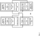
- FIG. 2 is a block diagram of the system 200 for enabling printing of a barcode.
- the system 200 includes the same multifunction peripheral 210, desktop computer 220, mobile device 230, and barcode printer 240 of FIG. 1 .
- This figure is intentionally simplified to focus only on those elements that are most relevant to this disclosure. As a result, components or functions have been omitted that may or may not be present in each element of this system 200.
- the multifunction peripheral 210 includes, at least, a raster image processor 211 and print hardware 212.
- the raster image processor 211 converts print jobs into visible images that are output on physical documents.
- the raster image processor 211 is described as a raster image processor 211, but in some cases may include specialized image processing capabilities, particularly in cases in which the multifunction peripheral 210 includes the capability to print other types of barcodes or encode information in RFID tags.
- the multifunction peripheral 210 also includes print hardware 212 that is physical hardware responsible for outputting physical documents and/or barcodes once the raster image processor 211 has converted any printer language document received into printing instructions for the print hardware 212.
- the print hardware may include traditional printing hardware, as well as any specialized hardware (e.g. RFID tag encoding hardware).
- the barcode printer 240 also includes an image processor 241 and print hardware 242.
- the barcode printer 240 is, preferably, a specialized printer suitable for printing a barcode or encoding non-visual information.
- a barcode may be an actual barcode, but may take other forms, such as RFID tag encoding.
- specialized barcode printer software on a computing device was required to interface with the barcode printer 240 so as to output barcodes.
- the image processor 241 performs much the same processes as the raster image processor 211, but the printer language may be distinct and special given that this is a barcode printer 240. Likewise, the image processor 241 receives print jobs and outputs those jobs to the print hardware 242 so that a barcode may be printed.
- the desktop computer 220 and mobile device 230 each include an operating system 221, 231; a word processor 222, 232; and a print driver 223, 233. Both the desktop computer 220 and the mobile device 230 are shown only to indicate that both are possible. As discussed above, the multifunction peripheral may include these components as well in some cases.
- the operating system 221, 231 manages the base level operations of the desktop computer 220 and the mobile device 230.
- the word processor 222, 232 is a typical software application that is used to input, organize, and arrange words, typically for consumption in textual documents.
- Microsoft® Word® is the most common word processor. Though described as a word processor application, in some cases, the word processor 222, 232 may actually be a different type of application, such as a spreadsheet application, a publishing application (e.g. Adobe® Reader®), or a presentation application (e.g. Microsoft® PowerPoint®).
- a spreadsheet application e.g. Adobe® Reader®
- a presentation application e.g. Microsoft® PowerPoint®
- the primary distinction for these applications is that they all rely upon a traditional, typical print driver 223, 233. They do not rely upon specialized software applications that are used specifically to generate barcodes or to enable printing by a barcode printer.
- printer drivers 223, 233 are software that enables the word processor 222, 232 to output documents for printing.
- the printer drivers 223, 233 may include detection capabilities to recognize portions of the text and images within the documents generated by the word processor as will be described more fully below.
- the computing device 300 may be representative of the server computers, client devices, mobile devices and other computing devices discussed herein.
- the computing device 300 may include software and/or hardware for providing functionality and features described herein.
- the computing device 300 may therefore include one or more of: logic arrays, memories, analog circuits, digital circuits, software, firmware and processors.
- the hardware and firmware components of the computing device 300 may include various specialized units, circuits, software and interfaces for providing the functionality and features described herein.
- the computing device 300 may have a processor 312 coupled to a memory 314, storage 318, a network interface 311 and an I/O interface 315.
- the processor may be or include one or more microprocessors and application specific integrated circuits (ASICs).
- the memory 314 may be or include RAM, ROM, DRAM, SRAM and MRAM, and may include firmware, such as static data or fixed instructions, BIOS, system functions, configuration data, and other routines used during the operation of the computing device 300 and processor 312.
- the memory 314 also provides a storage area for data and instructions associated with applications and data handled by the processor 312.
- the word memory specifically excludes transitory medium such as signals and propagating waveforms.
- the storage 318 may provide non-volatile, bulk or long term storage of data or instructions in the computing device 300.
- the storage 318 may take the form of a disk, tape, CD, DVD, or other reasonably high capacity addressable or serial storage medium.
- Multiple storage devices may be provided or available to the computing device 300. Some of these storage devices may be external to the computing device 300, such as network storage or cloud-based storage.
- the word storage specifically excludes transitory medium such as signals and propagating waveforms.
- the network interface 311 may be configured to interface to a network such as network 150 ( FIG. 1 ).
- the I/O interface 315 may be configured to interface the processor 312 to peripherals (not shown) such as displays, keyboards and USB devices.
- FIG. 4 is a flowchart of a process for converting visible text into a barcode. The process begins with the start 405 and ends at end 495. The process may take place many times in a given document before it is transmitted to the printer at 490 (as discussed below).
- a user first accesses a document at 410.
- the user may access a document using the desktop computer 220 (for example) or the mobile device 230, or some other computing device.
- This access will typically entail opening a document or otherwise beginning the process of editing a document using software.
- this software is software with which the user is familiar, such as a typical word processing software.
- the document is displayed on a display of the device.
- the display may be connected to or otherwise visible to a user.
- the display makes the document visible to a user so that the user may interact with it, for example, by editing a document, adding text to the document, or otherwise formatting a document.
- FIG. 5 An example of an opened document appears in FIG. 5 .
- text 550 for which a barcode will not be created and text 552 for which a barcode will be created. The process is discussed more fully below.
- a user of the software may draw a geometric shape over or on top of the document, which may or may not be in a particular color at 430.
- the color may be important to enable the printer driver to more-easily recognize the portion of the document for which a barcode will be created for the printing device.
- FIG. 6 An example of such a document appears in FIG. 6 .
- the same text 650 for which a barcode will not be created remains visible, but now there is a geometric shape (in this case a rectangle) superimposed over the text 652 which will be converted into a barcode.
- this geometric shape 660 was drawn using the geometric shape drawing functionality inherent in the word processing application.
- the interior of the geometric shape 660 may be colored a particular color such as red, green, yellow or some other color.
- the shape or color would appear behind the text or be translucent, and generally would not be the same color as the text, because text would not be visible to a human behind that shape.
- colors corresponding to the text including a black shape over black text, may be used if necessary because the textual content behind the shape will always be readable to the computer and print driver so long as it is stored in the associated file type.
- the data for the document is saved merely as an image.
- a translucent overlay relative to the text, may be required because the print driver may be required to perform optical character recognition ("OCR") for the text behind the shape. If the print driver is unable to "see” the text at all, because the shape completely covers the text, then OCR will be impossible, and the desired text to barcode conversion will not function.
- OCR optical character recognition
- a user may open a document in Microsoft® Word®. The user may then use the insert shape function to draw a shape on the document. Alternatively, if a user uses Adobe® Reader®, he or she may use the tool function to insert an image or a geometric shape.
- the program a user uses is not particularly important, so long as the program has a capability of allowing a user to insert a geometric shape with a particular color.
- the process by which the shape is drawn may take many forms.
- a user may use a tool to create a series of joined lines, or they may use a tool provided by the software for drawing preset geometric shapes such as a hexagon or parallelogram.
- the associated software e.g. word processing software, PDF viewer software, spreadsheet software
- the associated software will interpret actions by the user to draw "shapes" as overlays on top of existing documents or portions of text within documents, and will translate that information into information, along with the print driver, suitable for instructing a print device to output that color and shape in the location on the associated document generated through that user action.
- the print driver may, in turn, translate it further into an indication by the user of a desire to convert the underlying text into a barcode, as discussed herein.
- Geometric shapes may be simple or complex. A user may draw a rectangle of a particular height and width and the software may be preprogrammed to understand that such dimensions are associated with adding a barcode. Additionally, specific colors may be used to define whether or not a barcode should be placed. For example, if a geometric shape is particularly large or particularly small, it may be ignored. Likewise, specific geometric shapes may be required (e.g. the system may only recognize rectangles and squares and may ignore circles and triangles). In other cases, all types of shapes may be recognized.
- particular shapes may indicate particular actions to take place (e.g. rectangles may mean that a barcode should be created, but trapezoids may indicate that a QR code should be created from the underlying text).
- different colored rectangles or squares may indicate different types of codes (e.g. red is a barcode, green is a QR code).
- color-coding may be used to indicate print parameters or other characteristics of the barcodes themselves. So, for example, a green rectangle may mean that a barcode should be printed with as low a resolution (e.g. 75 dpi) as possible, while a red rectangle may be an intermediate resolution (e.g. 300 dpi) and a blue rectangle may mean as high a resolution as possible (e.g.
- barcodes e.g. QR codes
- QR codes can rely upon or use colors as a part of their encoding. Certain colors of the geometric shapes may indicate that color QR codes should be used while other colors may indicate that only black and white QR codes should be used.
- the particular actions to take place may be based on the associated text itself.
- RFID tags can encode thousands of bytes of data, which cannot easily be placed within a geometric shape due to limitations such as font size or available space in the document. Therefore, the associated text may represent a resource (such as the name of a file) which the printer driver could read in and treat as the data to encode into the RFID tag.
- the particular actions to take place may be actions other than barcode generation for the associated text.
- a blue colored region with an email address inside may be detected and may instruct the print driver to email the document to the email address within the colored region.
- Still further complex versions of this may involve emailing a barcode of converted text in a red colored region to the email address in the blue colored region.
- storing the document in a location identified either within a colored region or merely associated with a particular colored region in which the instruction to store the document is associated e.g. a red color, with or without any text within it, may indicate that the document should be stored on a particular cloud storage service or network location).
- the use of particular colors or geometric shapes could indicate different actions to take place. Those actions could include sending the text, or the document, or a barcode generated from the same another portion of text, to an email address, a facsimile number, a cloud storage service, or network storage device or location.
- the transmitted document may be the original document, a document bearing a barcode from converted text, as described herein, or simply the barcode itself, created from the colored region on the document.
- color coding may perform the same function.
- all "blue” geometric shapes may be for barcodes
- "yellow” geometric shapes may be for QR code generation
- all “red” geometric shapes may be for RFID tag creation.
- the associated color definition may be either broad or specific.
- a specific color with a specific designation may be required before it will be recognized. For example, if the print driver associates a color (e.g. red, which is represented hexadecimally as "#FF0000”) in the form of a rectangle for creation of a barcode, then one will only be created by an associated printer if the right geometric shape with the same color (“#FF0000”) is drawn by a user.
- a range of colors may be appropriate. For example, instead of only Hex Code #FF0000 indicating a requirement for barcode generation, any shade or a limited (predetermined) spectrum of red may designate a barcode needing to be drawn. In other instances, more than one color or geometric shape may be selected to indicate a barcode. For example, a geometric shape that is either orange or green may be selected. And, all of these settings may be configured by a user or administrator.
- the document may be transmitted to the print driver at 440.
- the print driver performs several tasks.
- the driver determines whether there is a geometric shape within the document. Detection of geometric shapes may be accomplished in several ways. In the case of rectangles, the print driver may determine that a set of points define vectors that are "straight" (within a detected tolerance) with respect to one another. Alternatively, the printer driver may detect that each of two sets of lines within a certain range on a given page are parallel to one another (e.g. the left and right sides and the top and bottom sides, respectively). Again, the system may allow for some range of tolerance so that absolute exact parallel lines are not required. Rectangles are particularly useful because they are among the most easily detected shapes.
- the print driver language itself defines print operations in terms of lines, so, for example, detection of two horizontal lines in successive lines of a printed document can be quite simple for a print driver. In the cases of other shapes, different detection methods may be employed.
- the printer driver determines whether there is a usable color within the geometric shape.
- the determination of the presence of a proper color can be accomplished in several ways.
- colors may be quantized. Specifically, colors may be given ranges or tolerances. This limits the number of configurable colors to the user, but also reduces confusion by preventing similar colors from being used for different purposes.
- the quantization may take place in many forms, but one form that has been found to work for this process translates approximate detected colors into "angles" along a 360 degree arc.
- the detected geometric shape's color (which may originate as an RGB or CMYK color for example) is first transformed into the HSV (Hue, Saturation, Value) color model.
- HSV Hue, Saturation, Value
- the hue must be close to a multiple of 30 degrees, and the saturation and value must be close to 100%.
- the print driver detects printable content within the geometric shape at 460.
- This printable content can be any information that is able to be expressed in a barcode such as text, hyperlinks, pictures, images, audio files and the like.
- the print driver attempts to capture all content within the detected shape, but in some cases, some information may be too large to present in a single barcode or may remain undetected or indecipherable to the software. If the information is too large, it may be split in to multiple barcodes or truncated. Undetected and indecipherable content will almost certainly be omitted.
- any formatting of the text e.g. the angle, such as 0, 90, 180, or 270 degrees, relative to the document, that the text is placed at, and in some cases, any bolding or highlighting or italics, or underlines, etc.
- any formatting of the text e.g. the angle, such as 0, 90, 180, or 270 degrees, relative to the document, that the text is placed at, and in some cases, any bolding or highlighting or italics, or underlines, etc.
- all textual formatting may be represented and stored within the barcode information.
- Most printing systems allow transforming the coordinate space through affine transformations. The most common types of transformations include translation, scaling, and rotation. Transformations are typically done by concatenating transformation matrices.
- Printer drivers often use a transformation matrix in order to map coordinates in the printing system's coordinate space to the device's coordinate space. This information may be represented, to the extent the software enables doing so, within the resulting barcode. These types of transformations may alter the angle and format of the detected text (e.g. italics, at a 90 degree angle, relative to the page).
- Detecting the current angle of rotation as something will appear on the page, ⁇ can be done by multiplying two points against the current device and printing system transformation matrices and then obtaining the inverse tangent of the ratio of the two calculated projective coordinates.
- T d represents the current device transformation matrix
- T c represents the current printing system transformation matrix.
- the rounded angle of the text detected at 460 is not at 0, 90, 180 or 270 degrees, it may be discarded, because most barcode printers are not capable of printing barcodes at any other angles.
- the process may repeat ("yes" at 475), so long as there are other geometric shapes within the document.
- barcodes are generated at 480.
- the angle of the barcode shall be the same as the angle determined before.
- Certain barcode printers may only be able to produce barcodes at discrete sizes.
- the size of the barcode will be the largest size supported by the barcode printer that is equal to or smaller than the size of the corresponding matched geometric shape.
- the barcode is preferably positioned on the page at the location detected at 460, and if it is smaller than the size of the geometric figure, it is centered both vertically and horizontally within the area of the detected geometric shape. In this way, the barcode will effectively "replace" the associated text that was within the geometric shape.
- a custom setting such as align left or align right of where the geometric figure was may be preprogrammed by the user, an administrator, or be a setting of the barcode printer.
- the data encoded in the barcode at 480 shall be barcode content that is representative of the text detected at 460 and encoded at 470. If there are no suitable characters (e.g. the text was illegible, nonsense, or otherwise unprocessable by the printer driver) after encoding at 470, a default or error image may be printed instead of a barcode in the same place as the detected geometric figure. The default or error image may indicate to the user that the associated text was not suitable for barcode generation. In other instances, no image may print at all and the portion may appear either as the inserted, colored geometric shape or as the original text. This may also be a setting set by a user, an administrator, or the printer itself. However, printing a figure may be preferable, because if no barcode prints at all a user may think there is something wrong with the overall function of the barcode printer, rather than that no printable text was detected.
- standard content or some other visual object may be incorporated into each barcode as the data is encoded.
- a particular logo, or default content e.g. a website, a hyperlink, or company name
- the default content may be automatically created, may be set by another color-coded, geometric shape within a document or set of documents (e.g. every time a yellow rectangle is detected, that text may be used as a default portion of a barcode printed such that it appears on each barcode in a set of documents).
- the document is then transmitted to a printer at 490 for output.
- the printer then outputs the document, including the replaced barcode(s) at 492.
- a physical document can be printed or a digital file with a barcode can be made.
- An example of such a document appears in FIG. 7 .
- the same text 750 that will not be replaced with a barcode is visible, but the text 652 ( FIG. 6 ) has now been converted into barcode 770.
- other forms of barcodes are possible as well.
- plural means two or more.
- a “set” of items may include one or more of such items.
- the terms “comprising”, “including”, “carrying”, “having”, “containing”, “involving”, and the like are to be understood to be open-ended, i.e., to mean including but not limited to. Only the transitional phrases “consisting of' and “consisting essentially of', respectively, are closed or semi-closed transitional phrases with respect to claims.
Abstract
Description
- A portion of the disclosure of this patent document contains material which is subject to copyright protection. This patent document may show and/or describe matter which is or may become trade dress of the owner. The copyright and trade dress owner has no objection to the facsimile reproduction by anyone of the patent disclosure as it appears in the Patent and Trademark Office patent files or records, but otherwise reserves all copyright and trade dress rights whatsoever.
- This disclosure relates to bar code and similar special-purpose printers. More specifically, this disclosure offers improvements in the usability of special-purpose printers from desktop based document-oriented software such as traditional word processors.
- Currently, utilizing a barcode printer's built-in capabilities to render barcodes is done through bespoke software, or through a more generic label-design software. The bespoke software is software specifically designed for barcode generation, typically created by the barcode printers. Numerous downsides exist for this software. The most obvious being that it requires a specific installation on each and every computer from which barcodes will be or may be printed. Others include that it is generally updated rarely and, over time, often goes out of support. Either the operating system is upgraded at some point such that the barcode software is no longer supported, or the barcode software ceases being upgraded and becomes inoperative. In addition, specialized training and familiarity for users is required in order to operate the barcode software. Though such software is generally not difficult to operate, it can be yet another system that requires training or updating or otherwise is required and if that could be eliminated, it would make IT support staff's jobs, and the user's jobs, simpler. The operation of most barcode software is often convoluted through poor user experience, user interface design, and complicated menus and instructions. The user experience is much less than ideal.
- As used herein, "barcode" means a traditional series of vertical lines barcode, a two-dimensional barcode such as a QR code, PDF417 code, DataMatrix code or other, similar two-dimensional barcodes, an RFID (radio frequency identification) tag, or any other type of print that is not human-readable text and appears on, is created on, or superimposed upon a document. Similarly, a "barcode printer" as used herein means either a specialized printing device that prints barcodes or a general printing device (e.g. a multifunction printer or peripheral) that may be instructed to, and is capable of, printing barcodes. The "printing" of a barcode may actually involve writing some text or other content in a machine readable form that may or may not be visible (e.g. writing RFID tags).
- In contrast to typical barcode software, virtually every modern computer user is familiar with at least one word processor application. Microsoft® Word® is the most common example, but many other such software exist. However, users of software such as word processors must use external tools to generate barcodes which are then inserted into the document as images. Such tools often include extensions or specialized print drivers that enable the "printing" of barcodes. These external tools are often costly and slow down software and hardware speed. They also require extra training and are not user friendly. And, as discussed above, these tools are often not commonly updated.
- One other option is to merely print barcodes (or two-dimensional barcodes such as QR codes) using raster image processing. This is problematic for several reasons. For one, most barcode printers are typically lower in resolution than normal desktop or multifunction printers, and as a result, scaling artifacts can be introduced, reducing the quality and readability of the printed barcode. In some cases, the readability issues are so severe that later computer reading of the barcodes is negatively impacted. These issues may be mitigated through the use of vector based barcode images, however, in the case of either raster or vector barcode images, the printer's built-in capabilities to render clear and precise barcodes is entirely forgone. What is needed is a system that would enable any ordinary printer to generate high quality barcodes with the ease and use of a regular printer.
- One of the objects of the present invention is to improve prior art techniques and overcome at least some of the prior art problems as for instance above illustrated.
- According to a first aspect of the present invention, it is provided a system comprising a computing device including a processor; a display device coupled to the processor; a memory coupled to the processor, the memory storing program instructions that, when executed, cause the computing device to perform actions, comprising accessing an electronic document including printable content visible on the display device; receiving interaction from a user instructing the computing device to draw a geometric shape of a selected color in an area identified by the user within the printable content of the electronic document; transmitting the document including the geometric shape within the area to a printer driver; detecting, using the printer driver, the printable content within the area defined by the geometric shape; encoding, using the printer driver, the printable content within the area defined by the geometric shape, as a print job for output in a machine-readable format using a barcode printer; and transmitting the print job to the barcode printer for output, the print job encoded so as to replace the printable content within the area defined by the geometric shape with the machine-readable format.
- Optionally, the system according to the first aspect of the invention further comprises the barcode printer including a second processor; a second memory coupled to the second processor, the second memory storing program instructions that, when executed, cause the barcode printer to perform actions, comprising generating a visible machine-readable marker based upon the print job; and outputting a document including the machine-readable marker in place of the printable content within the area.
- Optionally, in the system according to the first aspect of the invention, the area is defined using a traditional word processing software, rather than specialized barcode design or printing software.
- Optionally, in the system according to the first aspect of the invention, the electronic document is in the form of a word processing document, a portable document format document, an image format document, CAD file, or a spreadsheet document.
- Optionally, in the system according to the first aspect of the invention, the processor identifies the geometric shape by identifying a set of tolerances for color and an identification of the geometric shape; determining the area to be suitable for the print job as machine-readable content if the geometric shape and the selected color are within a certain tolerance of a predetermined geometric shape and a predetermined color.
- Optionally, in the system according to the first aspect of the invention, the barcode contains additional predetermined information in addition to the printable content within the geometric shape.
- According to a second aspect of the present invention, it is provided a non-volatile machine-readable medium storing a program having instructions which when executed will cause a processor to access an electronic document including printable content visible on the display device; receive interaction from a user instructing the computing device to draw a geometric shape of a selected color in an area identified by the user within the printable content of the electronic document visible on the display device; transmit the document including the geometric shape within the area to a printer driver; detect, using the printer driver, the printable content within the area defined by the geometric shape; encode, using the printer driver, the printable content within the area defined by the geometric shape, as a print job for output in a machine-readable format using a barcode printer; and transmit the print job to the barcode printer for output, the print job encoding so as to replace the printable content within the area defined by the geometric shape with the machine readable format.
- Optionally, in the machine readable-medium according to the second aspect of the invention, the instructions will further cause the processor to generate visible machine-readable marker based upon the print job; and output a document including the machine-readable marker in place of the printable content within the area.
- Optionally, in the machine readable-medium according to the second aspect of the invention, the area is defined using a traditional word processing software, rather than specialized barcode design or printing software.
- Optionally, in the machine readable-medium according to the second aspect of the invention, the electronic document is in the form of a word processing document, a portable document format document, an image format document, CAD file, or a spreadsheet document.
- Optionally, in the machine readable-medium according to the second aspect of the invention, the processor identifies a geometric shape by identifying a set of tolerances for color and an identification of the geometric shape; and determining the area to be suitable for the print job as machine-readable content if the geometric shape and the selected color are within a certain tolerance of a predetermined geometric shape and a predetermined color.
- Optionally, in the machine readable-medium according to the second aspect of the invention, the barcode contains additional predetermined information in addition to the printable content within the geometric shape.
- According to a third aspect of the invention, it is provided a method for printing barcodes using unconventional printers and software comprising accessing an electronic document including printable content of the electronic document visible on the display device; receiving interaction from a user instructing the computing device to draw a geometric shape of a selected color in an area identified by the user within the printable content of the electronic document; transmitting the document including the geometric shape within the area to a printer driver; detecting, using the printer driver, the printable content within the area defined by the geometric shape; encoding, using the printer driver, the printable content within the area defined by the geometric shape, as a print job for output in a machine readable format using a barcode printer; and transmitting the print job to the barcode printer for output, the print job encoded so as to replace the printable content within the area defined by the geometric shape with the machine-readable format.
- Optionally, the method according to a third aspect of the invention further comprises generating visible machine-readable marker based upon the print job; and outputting a document including the machine-readable marker in place of the printable content within the area.
- Optionally, in the method according to a third aspect of the invention, the area is defined using a traditional word processing software, rather than specialized barcode design or printing software.
- Optionally, in the method according to a third aspect of the invention, the electronic document is in the form of a word processing document, a portable document format document, an image format document, CAD file, or a spreadsheet document.
- Optionally, in the method according to a third aspect of the invention, the processor identifies a geometric shape by identifying a set of tolerances for color and an identification of the geometric shape; determining the area to be suitable for the print job as machine-readable content if the geometric shape and the selected color are within a certain tolerance of a predetermined geometric shape and a predetermined color.
- According to a fourth aspect of the invention, it is provided a system comprising a computing device including: a processor; a display device coupled to the processor; a memory coupled to the processor, the memory storing program instructions that, when executed, cause the computing device to perform actions, comprising: accessing an electronic document including printable content within the electronic document visible on the display device; receiving interaction from a user instructing the computing device to draw a geometric shape of a selected color in an area identified by the user within the printable content of the electronic document; transmitting the document including the geometric shape within the area to a printer driver; detecting, using the printer driver, the printable content visible within the area defined by the geometric shape; and performing an action, based upon at least one of a color of the geometric shape within the area or the printable content within the area.
- Optionally, in the system according to the fourth aspect of the invention, the action is encoding, using the printer driver, the printable content visible on the display device within the area defined by the geometric shape, as a print job for output in a machine-readable format using a barcode printer; and transmitting the print job to the barcode printer for output, the print job encoded so as to replace the printable content visible on the display device within the area defined by the geometric shape with the machine-readable format.
- Optionally, in the system according to the fourth aspect of the invention, the action is a selected one of emailing at least a portion of the electronic document to a predetermined email address; emailing at least a portion of the electronic document to an email address by the printable content within the area; sending a facsimile of at least a portion of the electronic document to a predetermined facsimile number; sending a facsimile of at least a portion of the electronic document to a facsimile number by the printable content within the area; and storing at least a portion of the electronic document to a remote storage location identified by the printable content within the area.
-
-
FIG. 1 is an example system for enabling printing of a barcode. -
FIG. 2 is a block diagram of the system for enabling printing of a barcode. -
FIG. 3 is a block diagram of a computing device. -
FIG. 4 is a flowchart of a process for converting visible text into a barcode. -
FIG. 5 is an example document in which some of the text is to be converted into a barcode. -
FIG. 6 is an example document having a geometric shape with color added over some of the text. -
FIG. 7 is an example document with a barcode having replaced some of the text. - Throughout this description, elements appearing in figures are assigned three-digit reference designators, where the most significant digit is the figure number where the element is introduced, and the two least significant digits are specific to the element. An element that is not described in conjunction with a figure may be presumed to have the same characteristics and function as a previously-described element having the same reference designator.
- Barcode printers have built-in capabilities for generating numerous different types of barcodes, and many printer models are also capable of encoding information into RFID tags and other non-visual information. Ordinarily this functionality is given to the user through label-design software. However, such software is not suitable for other tasks, such as word processing, or making spreadsheets, or complicated graphical design work. Additionally, such software is highly proprietary, expensive, and taxing on a typical computer's resources.
- Conversely word processing and spreadsheet software have become ubiquitous, they can be found on any computer and almost anyone using a computer can use such software with ease. Unfortunately, most word processing software lacks the capability of printing barcodes or interacting with a barcode printer. Additionally, if a software program were outfitted to communicate with a barcode printer, the additional code required tends to make such software programs operate more slowly and less-responsively.
- A workaround to this issue is to insert barcodes (e.g. two-dimensional barcodes such as QR codes) into the document itself as images. This solution is not ideal because if a barcode printer is used to print such documents, the printer's barcode printing capabilities are not utilized. Further, resolution is often lost rendering some barcodes unusable (e.g. unscannable by barcode scanners). Additionally, some print-like functions such as RFID tag encoding simply cannot be performed this way. Barcode printers also often have low data communication rates and sending the data of a barcode image to the printer can be substantially slower than simply sending a command to the barcode printer to generate the barcode.
- With few exceptions, barcode printers are monochrome devices. Printing color documents to a barcode printer is not a typical use case. Since colors are not typically used in documents destined to be printed via a barcode printer, colors can instead be given special meaning to the barcode printer driver.
- This disclosure overcomes issues with the prior art by allowing the user to not only visualize the placement and size of a barcode, but also know the content of the barcode before the document is printed. The user can rely upon software with which he or she is already very familiar and use functionalities (like inserting geometric shapes) that are relatively easy to add, adjust, and see. Thus, the user can know the content that will be the subject of the action within that geometric shape and doing so relies upon well-known techniques and user interfaces. Additionally, the disclosure teaches utilization of the printer's built-in capabilities to render barcodes, ensuring the best possible barcode quality.
- Referring now to
FIG. 1 , is anexample system 100 for enabling printing of a barcode. Thesystem 100 includes a multifunction peripheral 110, adesktop computer 120, andmobile device 130, and abarcode printer 140, all interconnected by anetwork 150. The multifunction peripheral 110,desktop computer 120, andmobile device 130 are examples of computing devices (FIG. 3 ). - The multifunction peripheral 110 is a traditional printing device that may include other functions such as scanning, transmitting and/or receiving facsimiles, optical character recognition functions, transmitting and/or receiving email, or other functions. The multifunction peripheral may include a rather simple user interface for basic commands regarding the above functions or, in some cases, may be essentially another computing device that is capable of performing the functions described herein with respect to the computing devices, including the
desktop computer 120 and themobile device 130. As discussed further herein, the multifunction peripheral 110 may simply output documents and/or barcodes created by themobile device 130 anddesktop computer 120, or may also generate or be used to generate barcodes as described herein in addition to outputting them once that process is complete. In that sense, the multifunction peripheral may operate both as a computing device and as an output device. - The
desktop computer 120 is a computing device as described below. The desktop computer may incorporate word processing software, along with other software and functionality, that enable thedesktop computer 120 to operate as described herein to identify text for conversion into barcodes. The desktop computer may communicate with printing devices, such as the multifunction peripheral 110 and thebarcode printer 140 using thenetwork 150. Though shown as a "desktop" computer, thisdesktop computer 120 may be a laptop, tablet, or other similar device capable of using word processing software and outputting to a printing device. - The
mobile device 130 is a computing device as discussed more fully below. Themobile device 130 is intended to be representative of so-called smart phones which may also operate as disclosed herein to label textual content for outputting viabarcode printer 140 or multifunction peripheral 110 as a barcode. - The
barcode printer 140 may be specialized hardware that only, or primarily, prints barcodes (as defined above). This may be an actual printer of barcodes, but it may also be a QR code printer, an RFID label printer, or some other similar form of machine-readable content that may be affixed to or integrated into a printed document or physical object (e.g. a box). - The
network 150 may be or include the internet, but is primarily used as a communications system for enabling the various components of thesystem 100 to communicate with one another. -
FIG. 2 is a block diagram of thesystem 200 for enabling printing of a barcode. Thesystem 200 includes the same multifunction peripheral 210,desktop computer 220,mobile device 230, andbarcode printer 240 ofFIG. 1 . This figure is intentionally simplified to focus only on those elements that are most relevant to this disclosure. As a result, components or functions have been omitted that may or may not be present in each element of thissystem 200. - The multifunction peripheral 210 includes, at least, a
raster image processor 211 andprint hardware 212. Theraster image processor 211 converts print jobs into visible images that are output on physical documents. Theraster image processor 211 is described as araster image processor 211, but in some cases may include specialized image processing capabilities, particularly in cases in which the multifunction peripheral 210 includes the capability to print other types of barcodes or encode information in RFID tags. - The multifunction peripheral 210 also includes
print hardware 212 that is physical hardware responsible for outputting physical documents and/or barcodes once theraster image processor 211 has converted any printer language document received into printing instructions for theprint hardware 212. The print hardware may include traditional printing hardware, as well as any specialized hardware (e.g. RFID tag encoding hardware). - The
barcode printer 240 also includes animage processor 241 andprint hardware 242. Thebarcode printer 240 is, preferably, a specialized printer suitable for printing a barcode or encoding non-visual information. As discussed above, a barcode may be an actual barcode, but may take other forms, such as RFID tag encoding. Traditionally, specialized barcode printer software on a computing device was required to interface with thebarcode printer 240 so as to output barcodes. - The
image processor 241 performs much the same processes as theraster image processor 211, but the printer language may be distinct and special given that this is abarcode printer 240. Likewise, theimage processor 241 receives print jobs and outputs those jobs to theprint hardware 242 so that a barcode may be printed. - The
desktop computer 220 andmobile device 230 each include anoperating system word processor print driver desktop computer 220 and themobile device 230 are shown only to indicate that both are possible. As discussed above, the multifunction peripheral may include these components as well in some cases. - The
operating system desktop computer 220 and themobile device 230. Theword processor word processor typical print driver - Finally, the
printer drivers word processor printer drivers - Turning now to
FIG. 3 , a block diagram of a computing device is shown. Thecomputing device 300 may be representative of the server computers, client devices, mobile devices and other computing devices discussed herein. Thecomputing device 300 may include software and/or hardware for providing functionality and features described herein. Thecomputing device 300 may therefore include one or more of: logic arrays, memories, analog circuits, digital circuits, software, firmware and processors. The hardware and firmware components of thecomputing device 300 may include various specialized units, circuits, software and interfaces for providing the functionality and features described herein. - The
computing device 300 may have aprocessor 312 coupled to amemory 314,storage 318, anetwork interface 311 and an I/O interface 315. The processor may be or include one or more microprocessors and application specific integrated circuits (ASICs). - The
memory 314 may be or include RAM, ROM, DRAM, SRAM and MRAM, and may include firmware, such as static data or fixed instructions, BIOS, system functions, configuration data, and other routines used during the operation of thecomputing device 300 andprocessor 312. Thememory 314 also provides a storage area for data and instructions associated with applications and data handled by theprocessor 312. As used herein, the word memory specifically excludes transitory medium such as signals and propagating waveforms. - The
storage 318 may provide non-volatile, bulk or long term storage of data or instructions in thecomputing device 300. Thestorage 318 may take the form of a disk, tape, CD, DVD, or other reasonably high capacity addressable or serial storage medium. Multiple storage devices may be provided or available to thecomputing device 300. Some of these storage devices may be external to thecomputing device 300, such as network storage or cloud-based storage. As used herein, the word storage specifically excludes transitory medium such as signals and propagating waveforms. - The
network interface 311 may be configured to interface to a network such as network 150 (FIG. 1 ). - The I/
O interface 315 may be configured to interface theprocessor 312 to peripherals (not shown) such as displays, keyboards and USB devices. -
FIG. 4 is a flowchart of a process for converting visible text into a barcode. The process begins with thestart 405 and ends atend 495. The process may take place many times in a given document before it is transmitted to the printer at 490 (as discussed below). - Following the
start 405, a user first accesses a document at 410. The user may access a document using the desktop computer 220 (for example) or themobile device 230, or some other computing device. This access will typically entail opening a document or otherwise beginning the process of editing a document using software. Preferably, this software is software with which the user is familiar, such as a typical word processing software. - Next at 420, the document is displayed on a display of the device. The display may be connected to or otherwise visible to a user. The display makes the document visible to a user so that the user may interact with it, for example, by editing a document, adding text to the document, or otherwise formatting a document.
- An example of an opened document appears in
FIG. 5 . There istext 550 for which a barcode will not be created andtext 552 for which a barcode will be created. The process is discussed more fully below. - Returning to
FIG. 4 , a user of the software may draw a geometric shape over or on top of the document, which may or may not be in a particular color at 430. The color may be important to enable the printer driver to more-easily recognize the portion of the document for which a barcode will be created for the printing device. - An example of such a document appears in
FIG. 6 . Here, thesame text 650 for which a barcode will not be created remains visible, but now there is a geometric shape (in this case a rectangle) superimposed over thetext 652 which will be converted into a barcode. Importantly, thisgeometric shape 660 was drawn using the geometric shape drawing functionality inherent in the word processing application. Though not shown, the interior of thegeometric shape 660 may be colored a particular color such as red, green, yellow or some other color. Preferably, the shape or color would appear behind the text or be translucent, and generally would not be the same color as the text, because text would not be visible to a human behind that shape. However, even colors corresponding to the text, including a black shape over black text, may be used if necessary because the textual content behind the shape will always be readable to the computer and print driver so long as it is stored in the associated file type. - For some types of software (e.g. PDF viewers) the data for the document is saved merely as an image. In those types of software, a translucent overlay, relative to the text, may be required because the print driver may be required to perform optical character recognition ("OCR") for the text behind the shape. If the print driver is unable to "see" the text at all, because the shape completely covers the text, then OCR will be impossible, and the desired text to barcode conversion will not function.
- More typically, for example, a user may open a document in Microsoft® Word®. The user may then use the insert shape function to draw a shape on the document. Alternatively, if a user uses Adobe® Reader®, he or she may use the tool function to insert an image or a geometric shape. The program a user uses is not particularly important, so long as the program has a capability of allowing a user to insert a geometric shape with a particular color.
- The process by which the shape is drawn may take many forms. For example, a user may use a tool to create a series of joined lines, or they may use a tool provided by the software for drawing preset geometric shapes such as a hexagon or parallelogram.
- In each case, the associated software (e.g. word processing software, PDF viewer software, spreadsheet software) will interpret actions by the user to draw "shapes" as overlays on top of existing documents or portions of text within documents, and will translate that information into information, along with the print driver, suitable for instructing a print device to output that color and shape in the location on the associated document generated through that user action. The print driver may, in turn, translate it further into an indication by the user of a desire to convert the underlying text into a barcode, as discussed herein.
- Geometric shapes may be simple or complex. A user may draw a rectangle of a particular height and width and the software may be preprogrammed to understand that such dimensions are associated with adding a barcode. Additionally, specific colors may be used to define whether or not a barcode should be placed. For example, if a geometric shape is particularly large or particularly small, it may be ignored. Likewise, specific geometric shapes may be required (e.g. the system may only recognize rectangles and squares and may ignore circles and triangles). In other cases, all types of shapes may be recognized.
- In still other cases, particular shapes may indicate particular actions to take place (e.g. rectangles may mean that a barcode should be created, but trapezoids may indicate that a QR code should be created from the underlying text). Alternatively, different colored rectangles or squares may indicate different types of codes (e.g. red is a barcode, green is a QR code). Likewise, color-coding may be used to indicate print parameters or other characteristics of the barcodes themselves. So, for example, a green rectangle may mean that a barcode should be printed with as low a resolution (e.g. 75 dpi) as possible, while a red rectangle may be an intermediate resolution (e.g. 300 dpi) and a blue rectangle may mean as high a resolution as possible (e.g. 2400 dpi). Still more simply, occasionally barcodes (e.g. QR codes) can rely upon or use colors as a part of their encoding. Certain colors of the geometric shapes may indicate that color QR codes should be used while other colors may indicate that only black and white QR codes should be used.
- Alternatively, the particular actions to take place may be based on the associated text itself. For example, RFID tags can encode thousands of bytes of data, which cannot easily be placed within a geometric shape due to limitations such as font size or available space in the document. Therefore, the associated text may represent a resource (such as the name of a file) which the printer driver could read in and treat as the data to encode into the RFID tag.
- Alternatively, the particular actions to take place may be actions other than barcode generation for the associated text. For example, a blue colored region with an email address inside may be detected and may instruct the print driver to email the document to the email address within the colored region. Still further complex versions of this may involve emailing a barcode of converted text in a red colored region to the email address in the blue colored region. Or, storing the document in a location identified either within a colored region or merely associated with a particular colored region in which the instruction to store the document is associated (e.g. a red color, with or without any text within it, may indicate that the document should be stored on a particular cloud storage service or network location).
- The use of particular colors or geometric shapes could indicate different actions to take place. Those actions could include sending the text, or the document, or a barcode generated from the same another portion of text, to an email address, a facsimile number, a cloud storage service, or network storage device or location. The transmitted document may be the original document, a document bearing a barcode from converted text, as described herein, or simply the barcode itself, created from the colored region on the document.
- Similarly, color coding may perform the same function. For example, all "blue" geometric shapes may be for barcodes, while "yellow" geometric shapes may be for QR code generation, while all "red" geometric shapes may be for RFID tag creation. The associated color definition may be either broad or specific. In some instances, a specific color with a specific designation may be required before it will be recognized. For example, if the print driver associates a color (e.g. red, which is represented hexadecimally as "#FF0000") in the form of a rectangle for creation of a barcode, then one will only be created by an associated printer if the right geometric shape with the same color ("#FF0000") is drawn by a user.
- In other instances, a range of colors may be appropriate. For example, instead of only Hex Code #FF0000 indicating a requirement for barcode generation, any shade or a limited (predetermined) spectrum of red may designate a barcode needing to be drawn. In other instances, more than one color or geometric shape may be selected to indicate a barcode. For example, a geometric shape that is either orange or green may be selected. And, all of these settings may be configured by a user or administrator.
- When a user is finished modifying a document to add the desired geometric shapes and associated colors the document may be transmitted to the print driver at 440.
- Returning to
FIG. 4 , the print driver performs several tasks. First at 445, the driver determines whether there is a geometric shape within the document. Detection of geometric shapes may be accomplished in several ways. In the case of rectangles, the print driver may determine that a set of points define vectors that are "straight" (within a detected tolerance) with respect to one another. Alternatively, the printer driver may detect that each of two sets of lines within a certain range on a given page are parallel to one another (e.g. the left and right sides and the top and bottom sides, respectively). Again, the system may allow for some range of tolerance so that absolute exact parallel lines are not required. Rectangles are particularly useful because they are among the most easily detected shapes. They have a regular shape with two sets of parallel lines and an interior filled within those lines. In some cases, the print driver language itself defines print operations in terms of lines, so, for example, detection of two horizontal lines in successive lines of a printed document can be quite simple for a print driver. In the cases of other shapes, different detection methods may be employed. - If no geometric shape is detected ("no" at 445), then the process goes to 475 to determine if any further shapes are present. If there is a geometric shape detected ("yes" at 445), then the process moves on to determine if there is a usable color at 455.
- At 455, the printer driver determines whether there is a usable color within the geometric shape. The determination of the presence of a proper color can be accomplished in several ways. To simplify the detection of colored regions at 455, colors may be quantized. Specifically, colors may be given ranges or tolerances. This limits the number of configurable colors to the user, but also reduces confusion by preventing similar colors from being used for different purposes.
- The quantization may take place in many forms, but one form that has been found to work for this process translates approximate detected colors into "angles" along a 360 degree arc. Thus, the detected geometric shape's color (which may originate as an RGB or CMYK color for example) is first transformed into the HSV (Hue, Saturation, Value) color model. In this model, the hue must be close to a multiple of 30 degrees, and the saturation and value must be close to 100%. These tolerances can be adjusted by the user, but generally speaking, default tolerances of ±5 degrees for hue and up to 5% for saturation and value are suitable for most situations. This process of quantization means that there are twelve distinct usable hues. With full saturation and value, these colors are traditionally named so: Red (0 degrees), Orange (30 degrees), Yellow (60 degrees), Chartreuse (90 degrees), Green (120 degrees), Spring green (150 degrees), Cyan (180 degrees), Azure (210 degrees), Blue (240 degrees), Violet (270 degrees), Magenta (300 degrees), Rose (330 degrees).
- It should be apparent that other quantization systems could be used, but this one tends to provide sufficient ranges of leeway between the various hues, and still enables a suitable level of accuracy for the system to function with reliability in converting text to barcodes.
- If there is no usable color detected by the print driver ("no" at 455), then the document passes to 475. However, if there is a usable color ("yes" at 455), then the print driver detects printable content within the geometric shape at 460. This printable content can be any information that is able to be expressed in a barcode such as text, hyperlinks, pictures, images, audio files and the like. The print driver attempts to capture all content within the detected shape, but in some cases, some information may be too large to present in a single barcode or may remain undetected or indecipherable to the software. If the information is too large, it may be split in to multiple barcodes or truncated. Undetected and indecipherable content will almost certainly be omitted.
- In addition to capturing the text at 460, any formatting of the text (e.g. the angle, such as 0, 90, 180, or 270 degrees, relative to the document, that the text is placed at, and in some cases, any bolding or highlighting or italics, or underlines, etc.) is also recorded. If text is placed at more than one angle within the matched geometric figure, only the last angle may be stored. In more complex systems, all textual formatting may be represented and stored within the barcode information. Most printing systems allow transforming the coordinate space through affine transformations. The most common types of transformations include translation, scaling, and rotation. Transformations are typically done by concatenating transformation matrices. Printer drivers often use a transformation matrix in order to map coordinates in the printing system's coordinate space to the device's coordinate space. This information may be represented, to the extent the software enables doing so, within the resulting barcode. These types of transformations may alter the angle and format of the detected text (e.g. italics, at a 90 degree angle, relative to the page).
- Detecting the current angle of rotation as something will appear on the page, θ, can be done by multiplying two points against the current device and printing system transformation matrices and then obtaining the inverse tangent of the ratio of the two calculated projective coordinates. Below is an algorithm for determining the current angle of rotation, where Td represents the current device transformation matrix and Tc represents the current printing system transformation matrix.


- This will successfully detect the angle of rotation for the identified text within the geometric shape even after translation and isotropic scaling may have been applied. Other (much less common) affine transformations such as shearing and anisotropic scaling will affect the accuracy of this calculation. A user-configurable tolerance defaulting to ±5 degrees will allow for rounding errors, which are likely to occur after successive matrix concatenation with IEEE 754 floating point arithmetic.
- Depending on the capabilities of the barcode printer, if the rounded angle of the text detected at 460 is not at 0, 90, 180 or 270 degrees, it may be discarded, because most barcode printers are not capable of printing barcodes at any other angles.
- Once the printable content, and its angle, is detected, that content is encoded into a barcode at 470. The barcode for that printable content will be presented at the same angle, and with as much of the associated formatting information as is possible given the limitations of the particular barcode printer.
- The process may repeat ("yes" at 475), so long as there are other geometric shapes within the document.
- Once all matched geometric figures are processed ("no" at 475), barcodes are generated at 480. The angle of the barcode shall be the same as the angle determined before. Certain barcode printers may only be able to produce barcodes at discrete sizes. The size of the barcode will be the largest size supported by the barcode printer that is equal to or smaller than the size of the corresponding matched geometric shape. The barcode is preferably positioned on the page at the location detected at 460, and if it is smaller than the size of the geometric figure, it is centered both vertically and horizontally within the area of the detected geometric shape. In this way, the barcode will effectively "replace" the associated text that was within the geometric shape.
- In some instances, a custom setting such as align left or align right of where the geometric figure was may be preprogrammed by the user, an administrator, or be a setting of the barcode printer.
- The data encoded in the barcode at 480 shall be barcode content that is representative of the text detected at 460 and encoded at 470. If there are no suitable characters (e.g. the text was illegible, nonsense, or otherwise unprocessable by the printer driver) after encoding at 470, a default or error image may be printed instead of a barcode in the same place as the detected geometric figure. The default or error image may indicate to the user that the associated text was not suitable for barcode generation. In other instances, no image may print at all and the portion may appear either as the inserted, colored geometric shape or as the original text. This may also be a setting set by a user, an administrator, or the printer itself. However, printing a figure may be preferable, because if no barcode prints at all a user may think there is something wrong with the overall function of the barcode printer, rather than that no printable text was detected.
- In some cases, standard content or some other visual object may be incorporated into each barcode as the data is encoded. For example, a particular logo, or default content (e.g. a website, a hyperlink, or company name) may be combined with the barcode as it is encoded. The default content may be automatically created, may be set by another color-coded, geometric shape within a document or set of documents (e.g. every time a yellow rectangle is detected, that text may be used as a default portion of a barcode printed such that it appears on each barcode in a set of documents).
- At 480, once the geometric shape is replaced with a barcode, the document is then transmitted to a printer at 490 for output. The printer then outputs the document, including the replaced barcode(s) at 492. A physical document can be printed or a digital file with a barcode can be made. An example of such a document appears in
FIG. 7 . As can be seen, thesame text 750 that will not be replaced with a barcode is visible, but the text 652 (FIG. 6 ) has now been converted intobarcode 770. As discussed above, other forms of barcodes are possible as well. - Thereafter, the process ends at 495.
- Throughout this description, the embodiments and examples shown should be considered as exemplars, rather than limitations on the apparatus and procedures disclosed or claimed. Although many of the examples presented herein involve specific combinations of method acts or system elements, it should be understood that those acts and those elements may be combined in other ways to accomplish the same objectives. With regard to flowcharts, additional and fewer steps may be taken, and the steps as shown may be combined or further refined to achieve the methods described herein. Acts, elements and features discussed only in connection with one embodiment are not intended to be excluded from a similar role in other embodiments.
- As used herein, "plurality" means two or more. As used herein, a "set" of items may include one or more of such items. As used herein, whether in the written description or the claims, the terms "comprising", "including", "carrying", "having", "containing", "involving", and the like are to be understood to be open-ended, i.e., to mean including but not limited to. Only the transitional phrases "consisting of' and "consisting essentially of', respectively, are closed or semi-closed transitional phrases with respect to claims. Use of ordinal terms such as "first", "second", "third", etc., in the claims to modify a claim element does not by itself connote any priority, precedence, or order of one claim element over another or the temporal order in which acts of a method are performed, but are used merely as labels to distinguish one claim element having a certain name from another element having a same name (but for use of the ordinal term) to distinguish the claim elements. As used herein, "and/or" means that the listed items are alternatives, but the alternatives also include any combination of the listed items.
Claims (15)
- A system comprising:a computing device including:a processor;a display device coupled to the processor;a memory coupled to the processor, the memory storing program instructions that, when executed, cause the computing device to perform actions, comprising:accessing an electronic document including printable content visible on the display device;receiving interaction from a user instructing the computing device to draw a geometric shape of a selected color in an area identified by the user within the printable content of the electronic document;transmitting the document including the geometric shape within the area to a printer driver;detecting, using the printer driver, the printable content within the area defined by the geometric shape;encoding, using the printer driver, the printable content within the area defined by the geometric shape, as a print job for output in a machine-readable format using a barcode printer; andtransmitting the print job to the barcode printer for output, the print job encoded so as to replace the printable content within the area defined by the geometric shape with the machine-readable format.
- The system of claim 1 further comprising:
the barcode printer including:a second processor;a second memory coupled to the second processor, the second memory storing program instructions that, when executed, cause the barcode printer to perform actions, comprising:generating a visible machine-readable marker based upon the print job; andoutputting a document including the machine-readable marker in place of the printable content within the area. - The system of claim 1 or 2, wherein the area is defined using a traditional word processing software, rather than specialized barcode design or printing software.
- The system of any of claims 1 to 3, wherein the electronic document is in the form of a word processing document, a portable document format document, an image format document, CAD file, or a spreadsheet document.
- The system of any of claims 1 to 4, wherein the processor identifies the geometric shape by:identifying a set of tolerances for color and an identification of the geometric shape;determining the area to be suitable for the print job as machine-readable content if the geometric shape and the selected color are within a certain tolerance of a predetermined geometric shape and a predetermined color.
- The system of any of claims 1 to 5, wherein the barcode contains additional predetermined information in addition to the printable content within the geometric shape.
- A non-volatile machine-readable medium storing a program having instructions which when executed will cause a processor to:access an electronic document including printable content visible on the display device;receive interaction from a user instructing the computing device to draw a geometric shape of a selected color in an area identified by the user within the printable content of the electronic document visible on the display device;transmit the document including the geometric shape within the area to a printer driver;detect, using the printer driver, the printable content within the area defined by the geometric shape;encode, using the printer driver, the printable content within the area defined by the geometric shape, as a print job for output in a machine-readable format using a barcode printer; andtransmit the print job to the barcode printer for output, the print job encoding so as to replace the printable content within the area defined by the geometric shape with the machine readable format.
- The machine readable-medium of claim 7 wherein the instructions will further cause the processor to:generate visible machine-readable marker based upon the print job; andoutput a document including the machine-readable marker in place of the printable content within the area.
- The machine-readable medium of claim 7 or 8, wherein the area is defined using a traditional word processing software, rather than specialized barcode design or printing software.
- The machine readable medium of any of claims 7 to 9, wherein the processor identifies a geometric shape by:identifying a set of tolerances for color and an identification of the geometric shape; anddetermining the area to be suitable for the print job as machine-readable content if the geometric shape and the selected color are within a certain tolerance of a predetermined geometric shape and a predetermined color.
- A method for printing barcodes using unconventional printers and software comprising;
accessing an electronic document including printable content of the electronic document visible on the display device;
receiving interaction from a user instructing the computing device to draw a geometric shape of a selected color in an area identified by the user within the printable content of the electronic document;
transmitting the document including the geometric shape within the area to a printer driver;
detecting, using the printer driver, the printable content within the area defined by the geometric shape;
encoding, using the printer driver, the printable content within the area defined by the geometric shape, as a print job for output in a machine readable format using a barcode printer; and
transmitting the print job to the barcode printer for output, the print job encoded so as to replace the printable content within the area defined by the geometric shape with the machine-readable format. - The method of claim 11 further comprising:generating visible machine-readable marker based upon the print job; andoutputting a document including the machine-readable marker in place of the printable content within the area.
- A system comprising:a computing device including:a processor;a display device coupled to the processor;a memory coupled to the processor, the memory storing program instructions that, when executed, cause the computing device to perform actions, comprising:accessing an electronic document including printable content within the electronic document visible on the display device;receiving interaction from a user instructing the computing device to draw a geometric shape of a selected color in an area identified by the user within the printable content of the electronic document;transmitting the document including the geometric shape within the area to a printer driver;detecting, using the printer driver, the printable content visible within the area defined by the geometric shape; andperforming an action, based upon at least one of a color of the geometric shape within the area or the printable content within the area.
- The system of claim 13, wherein the action is:encoding, using the printer driver, the printable content visible on the display device within the area defined by the geometric shape, as a print job for output in a machine-readable format using a barcode printer; andtransmitting the print job to the barcode printer for output, the print job encoded so as to replace the printable content visible on the display device within the area defined by the geometric shape with the machine-readable format.
- The system of claim 13 or 14, wherein the action is a selected one of:emailing at least a portion of the electronic document to a predetermined email address;emailing at least a portion of the electronic document to an email address by the printable content within the area;sending a facsimile of at least a portion of the electronic document to a predetermined facsimile number;sending a facsimile of at least a portion of the electronic document to a facsimile number by the printable content within the area; andstoring at least a portion of the electronic document to a remote storage location identified by the printable content within the area.
Applications Claiming Priority (1)
| Application Number | Priority Date | Filing Date | Title |
|---|---|---|---|
| US16/279,833 US20200265278A1 (en) | 2019-02-19 | 2019-02-19 | Colored region barcode printing |
Publications (1)
| Publication Number | Publication Date |
|---|---|
| EP3699748A1 true EP3699748A1 (en) | 2020-08-26 |
Family
ID=69156331
Family Applications (1)
| Application Number | Title | Priority Date | Filing Date |
|---|---|---|---|
| EP20150949.4A Withdrawn EP3699748A1 (en) | 2019-02-19 | 2020-01-09 | Colored region barcode printing |
Country Status (4)
| Country | Link |
|---|---|
| US (2) | US20200265278A1 (en) |
| EP (1) | EP3699748A1 (en) |
| JP (1) | JP7469883B2 (en) |
| CN (1) | CN111580759A (en) |
Families Citing this family (1)
| Publication number | Priority date | Publication date | Assignee | Title |
|---|---|---|---|---|
| KR20200045012A (en) * | 2013-07-15 | 2020-04-29 | 소니 주식회사 | Extensions of motion-constrained tile sets sei message for interactivity |
Citations (3)
| Publication number | Priority date | Publication date | Assignee | Title |
|---|---|---|---|---|
| US20070019222A1 (en) * | 2005-07-21 | 2007-01-25 | Fuji Xerox Co., Ltd. | Printer, printer driver, printing system, and print controlling method |
| US20070176000A1 (en) * | 2006-01-31 | 2007-08-02 | Konica Minolta Systems Laboratory, Inc. | Selective image encoding and replacement |
| EP2228751A2 (en) * | 2009-03-10 | 2010-09-15 | Canon Kabushiki Kaisha | Image processing apparatus, image processing method, and program |
Family Cites Families (10)
| Publication number | Priority date | Publication date | Assignee | Title |
|---|---|---|---|---|
| JPH11221946A (en) * | 1998-02-06 | 1999-08-17 | Casio Electronics Co Ltd | Print system and method |
| JP2000165651A (en) | 1998-11-27 | 2000-06-16 | Matsushita Electric Ind Co Ltd | Image reader |
| US7703002B2 (en) * | 2003-03-31 | 2010-04-20 | Ricoh Company, Ltd. | Method and apparatus for composing multimedia documents |
| FR2925993A1 (en) * | 2007-12-31 | 2009-07-03 | Radiotelephone Sfr | USING TOOL FOR AUTHENTICATION OF DOCUMENTS, METHODS OF USING THE TOOL AND DOCUMENTS PRODUCED BY THE METHOD (S) |
| JP5089524B2 (en) * | 2008-08-05 | 2012-12-05 | 株式会社リコー | Document processing apparatus, document processing system, document processing method, and document processing program |
| JP2010225038A (en) * | 2009-03-25 | 2010-10-07 | Fuji Xerox Co Ltd | Barcode information management device, and printer |
| US9240058B1 (en) | 2011-07-12 | 2016-01-19 | A9.Com, Inc. | Dynamic barcode generation for content location |
| US20140298223A1 (en) | 2013-02-06 | 2014-10-02 | Peter Duong | Systems and methods for drawing shapes and issuing gesture-based control commands on the same draw grid |
| JP2017017641A (en) | 2015-07-06 | 2017-01-19 | コニカミノルタ株式会社 | Document output system, document output method, and computer program |
| US20180278795A1 (en) * | 2017-03-22 | 2018-09-27 | Kabushiki Kaisha Toshiba | System and method of generating barcodes on scanned documents |
-
2019
- 2019-02-19 US US16/279,833 patent/US20200265278A1/en not_active Abandoned
-
2020
- 2020-01-09 EP EP20150949.4A patent/EP3699748A1/en not_active Withdrawn
- 2020-01-15 JP JP2020004081A patent/JP7469883B2/en active Active
- 2020-02-14 CN CN202010092979.5A patent/CN111580759A/en not_active Withdrawn
- 2020-04-29 US US16/861,635 patent/US11138484B2/en active Active
Patent Citations (3)
| Publication number | Priority date | Publication date | Assignee | Title |
|---|---|---|---|---|
| US20070019222A1 (en) * | 2005-07-21 | 2007-01-25 | Fuji Xerox Co., Ltd. | Printer, printer driver, printing system, and print controlling method |
| US20070176000A1 (en) * | 2006-01-31 | 2007-08-02 | Konica Minolta Systems Laboratory, Inc. | Selective image encoding and replacement |
| EP2228751A2 (en) * | 2009-03-10 | 2010-09-15 | Canon Kabushiki Kaisha | Image processing apparatus, image processing method, and program |
Also Published As
| Publication number | Publication date |
|---|---|
| CN111580759A (en) | 2020-08-25 |
| US11138484B2 (en) | 2021-10-05 |
| JP2020135862A (en) | 2020-08-31 |
| US20200265278A1 (en) | 2020-08-20 |
| US20200265279A1 (en) | 2020-08-20 |
| JP7469883B2 (en) | 2024-04-17 |
Similar Documents
| Publication | Publication Date | Title |
|---|---|---|
| US8614833B2 (en) | Printer, printer driver, printing system, and print controlling method | |
| US8225200B2 (en) | Extracting a character string from a document and partitioning the character string into words by inserting space characters where appropriate | |
| US8451489B1 (en) | Content-aware method for saving paper and ink while printing a PDF document | |
| US5606649A (en) | Method of encoding a document with text characters, and method of sending a document with text characters from a transmitting computer system to a receiving computer system | |
| US9442680B2 (en) | Image forming apparatus having toner saving function and method for printing | |
| EP2126720B1 (en) | A method for aligning a modified document and an original document for comparison and difference highlighting | |
| US8467075B2 (en) | Printing control apparatus using a print setting, method and medium | |
| US20170004389A1 (en) | Image Processing Apparatus Generating Partially Erased Image Data and Supplementary Data Supplementing Partially Erased Image Data | |
| US10452944B2 (en) | Multifunction peripheral assisted optical mark recognition using dynamic model and template identification | |
| US11138484B2 (en) | Colored region barcode printing | |
| US20130027730A1 (en) | Computer-Readable Recording Medium Storing Printer Driver for Causing Computer to Convert Text or Vector Object into Raster Object, and Printing Method with the Printer Driver | |
| US6891970B1 (en) | Image processing apparatus and method | |
| US10750038B2 (en) | Information processing apparatus, method of controlling the same, and non-transitory computer-readable recording medium therefor | |
| US11195069B2 (en) | Information processing apparatus configured to extract object from image data and generate printing data representing image including object, method of controlling the same, and non-transitory computer-readable recording medium therefor | |
| US6430321B1 (en) | Text enhancement | |
| US20120236377A1 (en) | Control devices for scanning documents, systems including such control devices, and non-transitory, computer-readable media storing instructions for such control devices | |
| US10168969B2 (en) | Information processing apparatus, non-transitory computer readable recording medium that records printer driver program, and blank page handling method | |
| US8990681B2 (en) | Method for aligning a modified document and an original document for comparison and difference highlighting | |
| US9940557B2 (en) | Document printing using hardware-dependent fonts | |
| JP6437076B2 (en) | Information processing apparatus, control method therefor, and program | |
| JP2013083862A (en) | Image processing device and image processing system | |
| US10884684B1 (en) | Image forming apparatus, image forming method, and non-transitory computer readable recording medium | |
| US8891112B2 (en) | Information processing apparatus and recording medium for increasing precision in detecting blank space | |
| US20140233051A1 (en) | Document distribution server and program for document distribution server | |
| JP2011062923A (en) | Printer controller, program for printer controller, and printing method |
Legal Events
| Date | Code | Title | Description |
|---|---|---|---|
| PUAI | Public reference made under article 153(3) epc to a published international application that has entered the european phase |
Free format text: ORIGINAL CODE: 0009012 |
|
| STAA | Information on the status of an ep patent application or granted ep patent |
Free format text: STATUS: THE APPLICATION HAS BEEN PUBLISHED |
|
| AK | Designated contracting states |
Kind code of ref document: A1 Designated state(s): AL AT BE BG CH CY CZ DE DK EE ES FI FR GB GR HR HU IE IS IT LI LT LU LV MC MK MT NL NO PL PT RO RS SE SI SK SM TR |
|
| AX | Request for extension of the european patent |
Extension state: BA ME |
|
| STAA | Information on the status of an ep patent application or granted ep patent |
Free format text: STATUS: REQUEST FOR EXAMINATION WAS MADE |
|
| 17P | Request for examination filed |
Effective date: 20210223 |
|
| RBV | Designated contracting states (corrected) |
Designated state(s): AL AT BE BG CH CY CZ DE DK EE ES FI FR GB GR HR HU IE IS IT LI LT LU LV MC MK MT NL NO PL PT RO RS SE SI SK SM TR |
|
| STAA | Information on the status of an ep patent application or granted ep patent |
Free format text: STATUS: EXAMINATION IS IN PROGRESS |
|
| 17Q | First examination report despatched |
Effective date: 20220818 |
|
| STAA | Information on the status of an ep patent application or granted ep patent |
Free format text: STATUS: THE APPLICATION HAS BEEN WITHDRAWN |
|
| 18W | Application withdrawn |
Effective date: 20221206 |