EP3699632B1 - A vehicle radar system for detecting preceding objects - Google Patents
A vehicle radar system for detecting preceding objects Download PDFInfo
- Publication number
- EP3699632B1 EP3699632B1 EP19158200.6A EP19158200A EP3699632B1 EP 3699632 B1 EP3699632 B1 EP 3699632B1 EP 19158200 A EP19158200 A EP 19158200A EP 3699632 B1 EP3699632 B1 EP 3699632B1
- Authority
- EP
- European Patent Office
- Prior art keywords
- vehicle
- ttc
- threshold value
- target
- ego
- Prior art date
- Legal status (The legal status is an assumption and is not a legal conclusion. Google has not performed a legal analysis and makes no representation as to the accuracy of the status listed.)
- Active
Links
Images


Classifications
-
- G—PHYSICS
- G01—MEASURING; TESTING
- G01S—RADIO DIRECTION-FINDING; RADIO NAVIGATION; DETERMINING DISTANCE OR VELOCITY BY USE OF RADIO WAVES; LOCATING OR PRESENCE-DETECTING BY USE OF THE REFLECTION OR RERADIATION OF RADIO WAVES; ANALOGOUS ARRANGEMENTS USING OTHER WAVES
- G01S13/00—Systems using the reflection or reradiation of radio waves, e.g. radar systems; Analogous systems using reflection or reradiation of waves whose nature or wavelength is irrelevant or unspecified
- G01S13/02—Systems using reflection of radio waves, e.g. primary radar systems; Analogous systems
- G01S13/50—Systems of measurement based on relative movement of target
- G01S13/52—Discriminating between fixed and moving objects or between objects moving at different speeds
-
- B—PERFORMING OPERATIONS; TRANSPORTING
- B60—VEHICLES IN GENERAL
- B60W—CONJOINT CONTROL OF VEHICLE SUB-UNITS OF DIFFERENT TYPE OR DIFFERENT FUNCTION; CONTROL SYSTEMS SPECIALLY ADAPTED FOR HYBRID VEHICLES; ROAD VEHICLE DRIVE CONTROL SYSTEMS FOR PURPOSES NOT RELATED TO THE CONTROL OF A PARTICULAR SUB-UNIT
- B60W30/00—Purposes of road vehicle drive control systems not related to the control of a particular sub-unit, e.g. of systems using conjoint control of vehicle sub-units
- B60W30/14—Adaptive cruise control
- B60W30/16—Control of distance between vehicles, e.g. keeping a distance to preceding vehicle
-
- B—PERFORMING OPERATIONS; TRANSPORTING
- B60—VEHICLES IN GENERAL
- B60W—CONJOINT CONTROL OF VEHICLE SUB-UNITS OF DIFFERENT TYPE OR DIFFERENT FUNCTION; CONTROL SYSTEMS SPECIALLY ADAPTED FOR HYBRID VEHICLES; ROAD VEHICLE DRIVE CONTROL SYSTEMS FOR PURPOSES NOT RELATED TO THE CONTROL OF A PARTICULAR SUB-UNIT
- B60W50/00—Details of control systems for road vehicle drive control not related to the control of a particular sub-unit, e.g. process diagnostic or vehicle driver interfaces
- B60W50/08—Interaction between the driver and the control system
- B60W50/14—Means for informing the driver, warning the driver or prompting a driver intervention
-
- G—PHYSICS
- G01—MEASURING; TESTING
- G01S—RADIO DIRECTION-FINDING; RADIO NAVIGATION; DETERMINING DISTANCE OR VELOCITY BY USE OF RADIO WAVES; LOCATING OR PRESENCE-DETECTING BY USE OF THE REFLECTION OR RERADIATION OF RADIO WAVES; ANALOGOUS ARRANGEMENTS USING OTHER WAVES
- G01S13/00—Systems using the reflection or reradiation of radio waves, e.g. radar systems; Analogous systems using reflection or reradiation of waves whose nature or wavelength is irrelevant or unspecified
- G01S13/02—Systems using reflection of radio waves, e.g. primary radar systems; Analogous systems
- G01S13/50—Systems of measurement based on relative movement of target
- G01S13/58—Velocity or trajectory determination systems; Sense-of-movement determination systems
- G01S13/583—Velocity or trajectory determination systems; Sense-of-movement determination systems using transmission of continuous unmodulated waves, amplitude-, frequency-, or phase-modulated waves and based upon the Doppler effect resulting from movement of targets
- G01S13/584—Velocity or trajectory determination systems; Sense-of-movement determination systems using transmission of continuous unmodulated waves, amplitude-, frequency-, or phase-modulated waves and based upon the Doppler effect resulting from movement of targets adapted for simultaneous range and velocity measurements
-
- G—PHYSICS
- G01—MEASURING; TESTING
- G01S—RADIO DIRECTION-FINDING; RADIO NAVIGATION; DETERMINING DISTANCE OR VELOCITY BY USE OF RADIO WAVES; LOCATING OR PRESENCE-DETECTING BY USE OF THE REFLECTION OR RERADIATION OF RADIO WAVES; ANALOGOUS ARRANGEMENTS USING OTHER WAVES
- G01S13/00—Systems using the reflection or reradiation of radio waves, e.g. radar systems; Analogous systems using reflection or reradiation of waves whose nature or wavelength is irrelevant or unspecified
- G01S13/02—Systems using reflection of radio waves, e.g. primary radar systems; Analogous systems
- G01S13/50—Systems of measurement based on relative movement of target
- G01S13/58—Velocity or trajectory determination systems; Sense-of-movement determination systems
- G01S13/62—Sense-of-movement determination
-
- G—PHYSICS
- G01—MEASURING; TESTING
- G01S—RADIO DIRECTION-FINDING; RADIO NAVIGATION; DETERMINING DISTANCE OR VELOCITY BY USE OF RADIO WAVES; LOCATING OR PRESENCE-DETECTING BY USE OF THE REFLECTION OR RERADIATION OF RADIO WAVES; ANALOGOUS ARRANGEMENTS USING OTHER WAVES
- G01S13/00—Systems using the reflection or reradiation of radio waves, e.g. radar systems; Analogous systems using reflection or reradiation of waves whose nature or wavelength is irrelevant or unspecified
- G01S13/66—Radar-tracking systems; Analogous systems
- G01S13/72—Radar-tracking systems; Analogous systems for two-dimensional [2D] tracking, e.g. combination of angle and range tracking, track-while-scan radar
- G01S13/723—Radar-tracking systems; Analogous systems for two-dimensional [2D] tracking, e.g. combination of angle and range tracking, track-while-scan radar by using numerical data
- G01S13/726—Multiple target tracking
-
- G—PHYSICS
- G01—MEASURING; TESTING
- G01S—RADIO DIRECTION-FINDING; RADIO NAVIGATION; DETERMINING DISTANCE OR VELOCITY BY USE OF RADIO WAVES; LOCATING OR PRESENCE-DETECTING BY USE OF THE REFLECTION OR RERADIATION OF RADIO WAVES; ANALOGOUS ARRANGEMENTS USING OTHER WAVES
- G01S13/00—Systems using the reflection or reradiation of radio waves, e.g. radar systems; Analogous systems using reflection or reradiation of waves whose nature or wavelength is irrelevant or unspecified
- G01S13/88—Radar or analogous systems specially adapted for specific applications
- G01S13/93—Radar or analogous systems specially adapted for specific applications for anti-collision purposes
- G01S13/931—Radar or analogous systems specially adapted for specific applications for anti-collision purposes of land vehicles
-
- G—PHYSICS
- G01—MEASURING; TESTING
- G01S—RADIO DIRECTION-FINDING; RADIO NAVIGATION; DETERMINING DISTANCE OR VELOCITY BY USE OF RADIO WAVES; LOCATING OR PRESENCE-DETECTING BY USE OF THE REFLECTION OR RERADIATION OF RADIO WAVES; ANALOGOUS ARRANGEMENTS USING OTHER WAVES
- G01S7/00—Details of systems according to groups G01S13/00, G01S15/00, G01S17/00
- G01S7/02—Details of systems according to groups G01S13/00, G01S15/00, G01S17/00 of systems according to group G01S13/00
- G01S7/41—Details of systems according to groups G01S13/00, G01S15/00, G01S17/00 of systems according to group G01S13/00 using analysis of echo signal for target characterisation; Target signature; Target cross-section
- G01S7/415—Identification of targets based on measurements of movement associated with the target
-
- B—PERFORMING OPERATIONS; TRANSPORTING
- B60—VEHICLES IN GENERAL
- B60W—CONJOINT CONTROL OF VEHICLE SUB-UNITS OF DIFFERENT TYPE OR DIFFERENT FUNCTION; CONTROL SYSTEMS SPECIALLY ADAPTED FOR HYBRID VEHICLES; ROAD VEHICLE DRIVE CONTROL SYSTEMS FOR PURPOSES NOT RELATED TO THE CONTROL OF A PARTICULAR SUB-UNIT
- B60W2520/00—Input parameters relating to overall vehicle dynamics
- B60W2520/10—Longitudinal speed
-
- B—PERFORMING OPERATIONS; TRANSPORTING
- B60—VEHICLES IN GENERAL
- B60W—CONJOINT CONTROL OF VEHICLE SUB-UNITS OF DIFFERENT TYPE OR DIFFERENT FUNCTION; CONTROL SYSTEMS SPECIALLY ADAPTED FOR HYBRID VEHICLES; ROAD VEHICLE DRIVE CONTROL SYSTEMS FOR PURPOSES NOT RELATED TO THE CONTROL OF A PARTICULAR SUB-UNIT
- B60W2520/00—Input parameters relating to overall vehicle dynamics
- B60W2520/10—Longitudinal speed
- B60W2520/105—Longitudinal acceleration
-
- B—PERFORMING OPERATIONS; TRANSPORTING
- B60—VEHICLES IN GENERAL
- B60W—CONJOINT CONTROL OF VEHICLE SUB-UNITS OF DIFFERENT TYPE OR DIFFERENT FUNCTION; CONTROL SYSTEMS SPECIALLY ADAPTED FOR HYBRID VEHICLES; ROAD VEHICLE DRIVE CONTROL SYSTEMS FOR PURPOSES NOT RELATED TO THE CONTROL OF A PARTICULAR SUB-UNIT
- B60W2554/00—Input parameters relating to objects
- B60W2554/80—Spatial relation or speed relative to objects
- B60W2554/802—Longitudinal distance
-
- B—PERFORMING OPERATIONS; TRANSPORTING
- B60—VEHICLES IN GENERAL
- B60W—CONJOINT CONTROL OF VEHICLE SUB-UNITS OF DIFFERENT TYPE OR DIFFERENT FUNCTION; CONTROL SYSTEMS SPECIALLY ADAPTED FOR HYBRID VEHICLES; ROAD VEHICLE DRIVE CONTROL SYSTEMS FOR PURPOSES NOT RELATED TO THE CONTROL OF A PARTICULAR SUB-UNIT
- B60W2754/00—Output or target parameters relating to objects
- B60W2754/10—Spatial relation or speed relative to objects
- B60W2754/30—Longitudinal distance
-
- G—PHYSICS
- G01—MEASURING; TESTING
- G01S—RADIO DIRECTION-FINDING; RADIO NAVIGATION; DETERMINING DISTANCE OR VELOCITY BY USE OF RADIO WAVES; LOCATING OR PRESENCE-DETECTING BY USE OF THE REFLECTION OR RERADIATION OF RADIO WAVES; ANALOGOUS ARRANGEMENTS USING OTHER WAVES
- G01S13/00—Systems using the reflection or reradiation of radio waves, e.g. radar systems; Analogous systems using reflection or reradiation of waves whose nature or wavelength is irrelevant or unspecified
- G01S13/88—Radar or analogous systems specially adapted for specific applications
- G01S13/93—Radar or analogous systems specially adapted for specific applications for anti-collision purposes
- G01S13/931—Radar or analogous systems specially adapted for specific applications for anti-collision purposes of land vehicles
- G01S2013/93185—Controlling the brakes
-
- G—PHYSICS
- G01—MEASURING; TESTING
- G01S—RADIO DIRECTION-FINDING; RADIO NAVIGATION; DETERMINING DISTANCE OR VELOCITY BY USE OF RADIO WAVES; LOCATING OR PRESENCE-DETECTING BY USE OF THE REFLECTION OR RERADIATION OF RADIO WAVES; ANALOGOUS ARRANGEMENTS USING OTHER WAVES
- G01S13/00—Systems using the reflection or reradiation of radio waves, e.g. radar systems; Analogous systems using reflection or reradiation of waves whose nature or wavelength is irrelevant or unspecified
- G01S13/88—Radar or analogous systems specially adapted for specific applications
- G01S13/93—Radar or analogous systems specially adapted for specific applications for anti-collision purposes
- G01S13/931—Radar or analogous systems specially adapted for specific applications for anti-collision purposes of land vehicles
- G01S2013/932—Radar or analogous systems specially adapted for specific applications for anti-collision purposes of land vehicles using own vehicle data, e.g. ground speed, steering wheel direction
-
- G—PHYSICS
- G01—MEASURING; TESTING
- G01S—RADIO DIRECTION-FINDING; RADIO NAVIGATION; DETERMINING DISTANCE OR VELOCITY BY USE OF RADIO WAVES; LOCATING OR PRESENCE-DETECTING BY USE OF THE REFLECTION OR RERADIATION OF RADIO WAVES; ANALOGOUS ARRANGEMENTS USING OTHER WAVES
- G01S13/00—Systems using the reflection or reradiation of radio waves, e.g. radar systems; Analogous systems using reflection or reradiation of waves whose nature or wavelength is irrelevant or unspecified
- G01S13/88—Radar or analogous systems specially adapted for specific applications
- G01S13/93—Radar or analogous systems specially adapted for specific applications for anti-collision purposes
- G01S13/931—Radar or analogous systems specially adapted for specific applications for anti-collision purposes of land vehicles
- G01S2013/9325—Radar or analogous systems specially adapted for specific applications for anti-collision purposes of land vehicles for inter-vehicle distance regulation, e.g. navigating in platoons
-
- G—PHYSICS
- G01—MEASURING; TESTING
- G01S—RADIO DIRECTION-FINDING; RADIO NAVIGATION; DETERMINING DISTANCE OR VELOCITY BY USE OF RADIO WAVES; LOCATING OR PRESENCE-DETECTING BY USE OF THE REFLECTION OR RERADIATION OF RADIO WAVES; ANALOGOUS ARRANGEMENTS USING OTHER WAVES
- G01S13/00—Systems using the reflection or reradiation of radio waves, e.g. radar systems; Analogous systems using reflection or reradiation of waves whose nature or wavelength is irrelevant or unspecified
- G01S13/88—Radar or analogous systems specially adapted for specific applications
- G01S13/93—Radar or analogous systems specially adapted for specific applications for anti-collision purposes
- G01S13/931—Radar or analogous systems specially adapted for specific applications for anti-collision purposes of land vehicles
- G01S2013/9327—Sensor installation details
- G01S2013/93271—Sensor installation details in the front of the vehicles
Definitions
- the present disclosure relates to a vehicle environment detection system comprising a control unit arrangement and at least one sensor arrangement that is arranged to be mounted in an ego vehicle and to provide sensor detections for at least two preceding target vehicles.
- Many vehicles comprise radar systems which are arranged for object detection, being able to provide a warning to a driver about an object in the path of a vehicle, as well as providing input to vehicle systems such as Adaptive Cruise Control (ACC) and Rear Cross Traffic Avoidance (RCTA) systems. These systems can provide both warnings and activate Autonomous Emergency Braking (AEB) to avoid a collision with an object behind a host vehicle.
- ACC Adaptive Cruise Control
- RCTA Rear Cross Traffic Avoidance
- AEB Autonomous Emergency Braking
- Such radar systems comprise one or more forward-looking radar transceivers and one or more rearward-looking radar transceivers in an ego vehicle.
- An ego vehicle can crash into a preceding vehicle if the preceding vehicle makes an unexpected deceleration or stop and/or if the driver of the ego vehicle fails to maintain a safe headway distance to the preceding vehicle.
- a vehicle radar can be used to detect the distance to a preceding vehicle and the relative speed between the preceding vehicle and the ego vehicle, and compute the time to collision (TTC) or the time required for the ego vehicle to reach the current position of the preceding vehicle (TTR).
- an alarm may be issued to encourage the vehicle operator to reduce the speed. It is then also possible to activate an emergency system such as an automated brake of the ego vehicle.
- a collision with a preceding vehicle can occur when a preceding vehicle collides with a further preceding vehicle traveling immediately ahead of the preceding vehicle, and the resulting sudden stopping or deceleration of the preceding vehicle can cause the ego vehicle to collide with the preceding vehicle.
- the preceding vehicle comes to a stop or decelerates so suddenly that it is extremely difficult for the ego vehicle to stop or decelerate quickly enough to avoid the collision with the preceding vehicle.
- the preceding vehicle may also have to brake quickly, which may be surprising to the driver of the ego vehicle. If the driver of the ego vehicle does not maintain a proper distance to the preceding vehicle, a collision can occur.
- the document US 2015025784 discloses a forward collision warning system in an ego vehicle that can determine time to collision with a preceding vehicle when there is a further preceding vehicle.
- a radar can detect preceding vehicles such as a first preceding vehicle and a second preceding vehicle immediately preceding the first preceding vehicle.
- the document US 7474253 discloses retrieving information about a vehicle in front of a preceding vehicle ahead of the ego vehicle, where correctly estimating a behavior of the vehicle in front of the preceding vehicle is used to smoothly control the speed of the ego vehicle.
- the document WO 15097511 describes a vehicle surrounding situation estimation device that can suitably estimate the vehicle surrounding situation even when the surrounding situation cannot be detected because of an abnormality generated in a sensor due to a collision.
- the document US 2014136044 relates to a method, and a system, for avoiding a collisions between host vehicle and one or more target objects disposed in the path of the host vehicle, one or more of which may not be visible to the driver of the host vehicle. Further in D1, the method and system determine whether it is likely that the host vehicle will collide with one or more target objects in the path of the host vehicle, and if so, take action.
- the object of the present disclosure is to provide a radar system that prevents collisions, in a more reliable way than previously described, in situations where there is a first preceding vehicle and at least a second preceding vehicle, where the a least one second preceding vehicle precedes the first preceding vehicle.
- a vehicle environment detection system comprising a control unit arrangement and at least one sensor arrangement that is arranged to be mounted in an ego vehicle and to provide sensor detections for at least two preceding target vehicles.
- the control unit arrangement is arranged to determine a resulting TTC (time to collision) between the ego vehicle and a closest preceding target vehicle, based on an ego velocity and an ego acceleration for the ego vehicle, a first distance between the ego vehicle and the closest preceding target vehicle.
- the resulting TTC is furthermore based on that target velocity and corresponding target acceleration for a preceding target vehicle among said target vehicles that provide a lowest TTC value.
- the vehicle environment detection system is adapted to determine vehicle data regarding an ego velocity and an ego acceleration for the ego vehicle.
- the vehicle environment detection system is adapted to determine further vehicle data comprising the first distance and a corresponding distance between the ego vehicle and each further preceding target vehicle, and corresponding target velocity and target acceleration for each preceding target vehicle.
- control unit arrangement is adapted to determine a corresponding initial TTC between the ego vehicle and each one of said preceding target vehicles.
- the control unit arrangement is further adapted to compare the determined initial TTC:s with a TTC threshold, and to only consider preceding vehicles that are associated with a corresponding initial TTC that falls below the TTC threshold when determining the resulting TTC.
- control unit arrangement is arranged to compare each initial TTC value that falls below the TTC threshold with a first initial threshold value and to initiate an alarm if any of these initial TTC values falls below the first initial threshold value.
- control unit arrangement is arranged to compare each initial TTC value that falls below the TTC threshold with a second initial threshold value, falling below the first initial threshold value, and to initiate an emergency system if any of these initial TTC values falls below the second initial threshold value.
- control unit arrangement is arranged to compare the resulting TTC with a first threshold value and to initiate an alarm if the resulting TTC falls below the first threshold value.
- control unit arrangement is arranged to compare the resulting TTC with a second threshold value, falling below the first threshold value, and to initiate an emergency system if the resulting TTC falls below the second threshold value.
- the control unit arrangement for each pair of any two preceding vehicles that travel successively one after the other among said at least two preceding vehicles, is arranged to determine a corresponding further TTC between the vehicles in each such pair, where the control unit arrangement is arranged to compare at least one further TTC from said determined further TTC:s with at least one further threshold value, and to adjust at least one of said first threshold value and second threshold value accordingly.
- Figure 1 schematically shows a top view of an ego vehicle 1 arranged to run in a first lane 2a on a road 2, where the ego vehicle 1 comprises a vehicle radar system 3.
- the vehicle radar system 3 comprises a radar sensor arrangement 4 that is arranged to distinguish and/or resolve targets from the surroundings by transmitting signal 6a, 7a and receiving corresponding reflected signals 6b, 7b and using a Doppler effect in a previously well-known manner.
- the signals 6a, 6b; 7a, 7b are according to some aspects constituted by sweep signals in the form of FMCW (Frequency Modulated Continuous Wave) chirp signals 6 of a previously known kind.
- FMCW Frequency Modulated Continuous Wave
- first preceding target vehicle 10 In front of the ego vehicle 1 there is a first preceding target vehicle 10, and in front of the first preceding target vehicle 10 there is a second preceding target vehicle 11, thus preceding the first preceding target vehicle 10.
- the vehicle radar system 3 further comprises a control unit arrangement 8 that is connected to the radar sensor arrangement 4 and is arranged to provide azimuth angles, distance and radial velocity of possible target object detections by simultaneously sampling and analyzing phase and amplitude of the received signals in a previously well-known manner. Azimuth angles are determined relative a radar reference line 5 that for example is constituted by a radar sensor arrangement boresight direction.
- the control unit arrangement 8 is also arranged to determine vehicle data regarding the own vehicle's, the ego vehicle's, ego velocity v 0 and ego acceleration a 0 .
- the control unit arrangement 8 is adapted to acquire these ego vehicle data from suitable sources, such as a speedometer arrangement 21 and an accelerometer arrangement 22 comprised in the ego vehicle 1 in a previously well-known manner.
- a first radar detection 9 of the first preceding target vehicle 10 and a second radar detection 12 of the second preceding target vehicle 11 are shown.
- the second radar detection 12 is acquired by having corresponding transmitted signals 7a and received reflected signals 7b bounced beneath the first preceding target vehicle 10.
- the sensor radar sensor arrangement 4 can be tilted vertically to achieve this, but it is also sufficient to have a radar sensor with a sufficient field of view in elevation direction.
- the second radar detection is acquired by having corresponding transmitted signals and received reflected signals reflected at guardrails or other structures along the road 2.
- the vehicle radar system 3 is arranged perform tracking of the preceding vehicles 10, 11 in a well-known manner, and to determine further vehicle data regarding:
- the control unit arrangement 8 is arranged to determine the first target acceleration a 1 for the first preceding target vehicle 10 and the second target acceleration a 2 for the second preceding target vehicle 11.
- control unit arrangement 8 is arranged to determine a resulting TTC (time to collision) between the ego vehicle 1 and the first preceding target vehicle 10, based on the ego velocity v 0 , the ego acceleration a 0 , the first distance r 1 , and those of the target velocity v 1 , v 2 and corresponding target acceleration a 1 , a 2 that provides the lowest value for the resulting TTC.
- control unit arrangement 8 is arranged to compare the determined TTC values with a first threshold value and to initiate an alarm if any TTC falls below the first threshold value. Such an alarm is intended to encourage the driver of the ego vehicle 1 to react in any suitable way, for example by appropriate steering and/or speed reduction.
- control unit arrangement 8 is arranged to compare the determined TTC values with a second threshold value, falling below the first threshold value. If any TTC falls below the second threshold value, the control unit arrangement 8 is arranged to initiate an emergency system such as an automated brake of the ego vehicle 1.
- the ego vehicle 1 comprises a safety control unit 13 and safety means 14, for example comprising an emergency braking system, seatbelt pretensioners and an alarm signal device.
- the safety control unit 13 is arranged to control the safety means 14 in dependence of input from the radar system 3. Such input may be conferred via the control unit arrangement 8.
- control unit arrangement 8 is arranged to determine a corresponding initial TTC between the ego vehicle 1 and each one of the preceding vehicles 10, 11, and to use the determined initial TTC:s for discarding preceding vehicles that are relatively far away when determining the resulting TTC.
- control unit arrangement 8 is arranged to compare the determined initial TTC:s with a TTC threshold, and only preceding vehicles that are associated with a corresponding initial TTC that falls below the TTC threshold are considered when determining the resulting TTC.
- control unit arrangement 8 is arranged to compare the determined initial TTC values that fall below the TTC threshold with a first initial threshold value and to initiate an alarm if any of these initial TTC values falls below the initial first threshold value. Such an alarm is intended to encourage the driver of the ego vehicle 1 to react in any suitable way, for example by appropriate steering and/or speed reduction.
- control unit arrangement 8 is arranged to compare the determined initial TTC values that fall below the TTC threshold with a second initial threshold value, falling below the first initial threshold value. If any of these initial TTC values falls below the second initial threshold value, the control unit arrangement 8 is arranged to initiate an emergency system such as an automated brake of the ego vehicle 1.
- the first initial threshold value equals the first threshold value and the second initial threshold value equals the second threshold value.
- the resulting TTC is determined irrespective of if any determined initial TTC value that falls below the TTC threshold also falls below any threshold value according to the above.
- control unit arrangement 8 is arranged to determine a first initial TTC between the ego vehicle 1 and the first preceding target vehicle 10 based on the ego velocity v 0 , the ego acceleration a 0 , the first distance r 1 , the first target velocity v 1 and the first target acceleration a 1 .
- the control unit arrangement 8 is also arranged to determine a second initial TTC between the ego vehicle 1 and the second preceding target vehicle 11 based on the ego velocity v 0 , the ego acceleration a 0 , the second distance r 2 the second target velocity v 2 and the second target acceleration a 2 .
- the second preceding vehicle 11 if the second preceding vehicle 11 is relatively far away such that the second initial TTC exceeds the TTC threshold, the second preceding vehicle 11 is not considered when the resulting TTC is determined The sudden braking of the second preceding vehicle 11 will consequently not affect the resulting TTC and not initiate any alarm or emergency system. A braking preceding vehicle that is relatively far away from the ego vehicle 1 does thus not have any impact on possible safety measures at the ego vehicle 1.
- the control unit arrangement 8 is arranged to compare the resulting TTC value with at least one threshold value and to initiate a proper action if any TTC falls below said threshold value.
- the present disclosure is also applicable for more than two preceding vehicles, but there are always at least two preceding vehicles 10, 11.
- control unit arrangement 8 for two or more preceding vehicles, for each pair of any two preceding vehicles that travel successively one after the other among said at least two preceding vehicles, the control unit arrangement 8 is arranged to determine a further TTC between the vehicles in each such pair. The control unit arrangement 8 is arranged to compare at least one further TTC from said determined further TTC:s with at least one further threshold value, and to adjust at least one of said first threshold value and second threshold value accordingly.
- a path prediction based on the driving state of the ego vehicle 1 is performed.
- a lane detection based on a vision system could be used, or a combination of both. This is independent of in which direction such a target vehicle 30 is travelling.
- the present disclosure also relates to a method for determining TTC, time to collision, between an ego vehicle 1 and a closest preceding target vehicle 10, where there are at least two preceding target vehicles 10, 11, the method comprising:
- the determining S3 for which preceding vehicles a resulting TTC shall be calculated comprises:
- the determining S3 for which preceding vehicles a resulting TTC shall be calculated comprises:
- the determining S3 for which preceding vehicles a resulting TTC shall be calculated comprises:
- the determining S3 for which preceding vehicles a resulting TTC shall be calculated comprises: only considering S301 preceding vehicles that are associated with a corresponding initial TTC that falls below the TTC threshold and exceeds all threshold values when determining the resulting TTC.
- the method further comprises:
- the method further comprises:
- the radar system may be implemented in any type of vehicle such as cars, trucks and buses as well as boats and aircraft.
- control unit arrangement 8 may be comprised by one or more separate or integrated control units.
- the safety control unit 13 is according to some aspects comprised in the control unit arrangement 8.
- tracked target vehicle generally, there can be any type of tracked target object such as for example a bicycle or a pedestrian.
- FMCW signals and FMCW signal configurations are also conceivable, as well as other types of Doppler radar signals.
- Other types of radar systems are also conceivable; not only FMCW radar systems are conceivable.
- Pulse radar, FSK (frequency-shift keying) or CW (continuous wave) waveform are also conceivable like all other kinds of suitable modulation techniques.
- the present disclosure does not only relate to vehicle radar systems but generally relates to any type of vehicle environment detection system such as ultrasonic or Lidar.
- the present disclosure relates to a vehicle environment detection system 3 comprising a control unit arrangement 8 and at least one sensor arrangement 4 that is arranged to be mounted in an ego vehicle 1 and to provide sensor detections 9, 12 for at least two preceding target vehicles 10, 11.
- the control unit arrangement 8 is arranged to determine a resulting TTC (time to collision) between the ego vehicle 1 and a closest preceding target vehicle 10, based on an ego velocity v 0 and an ego acceleration a 0 for the ego vehicle 1, a first distance r 1 between the ego vehicle 1 and the closest preceding target vehicle 10, and that target velocity v 1 , v 2 and corresponding target acceleration a 1 , a 2 for a preceding target vehicle 10, 11 among said target vehicles 10, 11 that provide a lowest TTC value.
- the vehicle environment detection system 3 is adapted to determine vehicle data regarding an ego velocity v 0 and an ego acceleration a 0 for the ego vehicle 1, and, by means of said sensor detections 9, 12, to determine further vehicle data comprising the first distance r 1 and a corresponding distance r 2 between the ego vehicle 1 and each further preceding target vehicle 11, and corresponding target velocity v 1 , v 2 and target acceleration a 1 , a 2 for each preceding target vehicle 10, 11.
- control unit arrangement 8 is adapted to determine a corresponding initial TTC between the ego vehicle 1 and each one of said preceding target vehicles 10, 11, and to compare the determined initial TTC:s with a TTC threshold, and to only consider preceding vehicles that are associated with a corresponding initial TTC that falls below the TTC threshold when determining the resulting TTC.
- control unit arrangement 8 is arranged to compare each initial TTC value that falls below the TTC threshold with a first initial threshold value and to initiate an alarm if any of these initial TTC values falls below the first initial threshold value.
- control unit arrangement 8 is arranged to compare each initial TTC value that falls below the TTC threshold with a second initial threshold value, falling below the first initial threshold value, and to initiate an emergency system if any of these initial TTC values falls below the second initial threshold value.
- control unit arrangement 8 is arranged to compare the resulting TTC with a first threshold value and to initiate an alarm if the resulting TTC falls below the first threshold value.
- control unit arrangement 8 is arranged to compare the resulting TTC with a second threshold value, falling below the first threshold value, and to initiate an emergency system if the resulting TTC falls below the second threshold value.
- control unit arrangement 8 for each pair of any two preceding vehicles that travel successively one after the other among said at least two preceding vehicles, the control unit arrangement 8 is arranged to determine a corresponding further TTC between the vehicles in each such pair, where the control unit arrangement 8 is arranged to compare at least one further TTC from said determined further TTC:s with at least one further threshold value, and to adjust at least one of said first threshold value and second threshold value accordingly.
Landscapes
- Engineering & Computer Science (AREA)
- Radar, Positioning & Navigation (AREA)
- Remote Sensing (AREA)
- Physics & Mathematics (AREA)
- Computer Networks & Wireless Communication (AREA)
- General Physics & Mathematics (AREA)
- Automation & Control Theory (AREA)
- Electromagnetism (AREA)
- Transportation (AREA)
- Mechanical Engineering (AREA)
- Human Computer Interaction (AREA)
- Traffic Control Systems (AREA)
Description
- The present disclosure relates to a vehicle environment detection system comprising a control unit arrangement and at least one sensor arrangement that is arranged to be mounted in an ego vehicle and to provide sensor detections for at least two preceding target vehicles.
- Many vehicles comprise radar systems which are arranged for object detection, being able to provide a warning to a driver about an object in the path of a vehicle, as well as providing input to vehicle systems such as Adaptive Cruise Control (ACC) and Rear Cross Traffic Avoidance (RCTA) systems. These systems can provide both warnings and activate Autonomous Emergency Braking (AEB) to avoid a collision with an object behind a host vehicle.
- Such radar systems comprise one or more forward-looking radar transceivers and one or more rearward-looking radar transceivers in an ego vehicle.
- An ego vehicle can crash into a preceding vehicle if the preceding vehicle makes an unexpected deceleration or stop and/or if the driver of the ego vehicle fails to maintain a safe headway distance to the preceding vehicle. A vehicle radar can be used to detect the distance to a preceding vehicle and the relative speed between the preceding vehicle and the ego vehicle, and compute the time to collision (TTC) or the time required for the ego vehicle to reach the current position of the preceding vehicle (TTR).
- If the TTC falls below a predetermined threshold value, an alarm may be issued to encourage the vehicle operator to reduce the speed. It is then also possible to activate an emergency system such as an automated brake of the ego vehicle.
- A collision with a preceding vehicle can occur when a preceding vehicle collides with a further preceding vehicle traveling immediately ahead of the preceding vehicle, and the resulting sudden stopping or deceleration of the preceding vehicle can cause the ego vehicle to collide with the preceding vehicle. In such a situation, the preceding vehicle comes to a stop or decelerates so suddenly that it is extremely difficult for the ego vehicle to stop or decelerate quickly enough to avoid the collision with the preceding vehicle.
- Even if the preceding vehicle does not collide with said further preceding vehicle, if said further preceding vehicle decelerates suddenly due to a need for a quick braking, the preceding vehicle may also have to brake quickly, which may be surprising to the driver of the ego vehicle. If the driver of the ego vehicle does not maintain a proper distance to the preceding vehicle, a collision can occur.
- The document
US 2015025784 discloses a forward collision warning system in an ego vehicle that can determine time to collision with a preceding vehicle when there is a further preceding vehicle. A radar can detect preceding vehicles such as a first preceding vehicle and a second preceding vehicle immediately preceding the first preceding vehicle. - The document
US 7474253 discloses retrieving information about a vehicle in front of a preceding vehicle ahead of the ego vehicle, where correctly estimating a behavior of the vehicle in front of the preceding vehicle is used to smoothly control the speed of the ego vehicle. - Further, the document
WO 15097511 - The document
US 2014136044 relates to a method, and a system, for avoiding a collisions between host vehicle and one or more target objects disposed in the path of the host vehicle, one or more of which may not be visible to the driver of the host vehicle. Further in D1, the method and system determine whether it is likely that the host vehicle will collide with one or more target objects in the path of the host vehicle, and if so, take action. - The object of the present disclosure is to provide a radar system that prevents collisions, in a more reliable way than previously described, in situations where there is a first preceding vehicle and at least a second preceding vehicle, where the a least one second preceding vehicle precedes the first preceding vehicle.
- This object is obtained by means of a vehicle environment detection system comprising a control unit arrangement and at least one sensor arrangement that is arranged to be mounted in an ego vehicle and to provide sensor detections for at least two preceding target vehicles. The control unit arrangement is arranged to determine a resulting TTC (time to collision) between the ego vehicle and a closest preceding target vehicle, based on an ego velocity and an ego acceleration for the ego vehicle, a first distance between the ego vehicle and the closest preceding target vehicle. The resulting TTC is furthermore based on that target velocity and corresponding target acceleration for a preceding target vehicle among said target vehicles that provide a lowest TTC value.
- In this way, in situations where there is a first preceding vehicle and at least a second preceding vehicle, where the at least one second preceding vehicle precedes the first preceding vehicle, collisions can be prevented in a reliable way.
- According to some aspects, the vehicle environment detection system is adapted to determine vehicle data regarding an ego velocity and an ego acceleration for the ego vehicle. By means of said sensor detections, the vehicle environment detection system is adapted to determine further vehicle data comprising the first distance and a corresponding distance between the ego vehicle and each further preceding target vehicle, and corresponding target velocity and target acceleration for each preceding target vehicle.
- According to some aspects, the control unit arrangement is adapted to determine a corresponding initial TTC between the ego vehicle and each one of said preceding target vehicles. The control unit arrangement is further adapted to compare the determined initial TTC:s with a TTC threshold, and to only consider preceding vehicles that are associated with a corresponding initial TTC that falls below the TTC threshold when determining the resulting TTC.
- In this way, situations that do not pose an imminent danger can be identified.
- According to some aspects, the control unit arrangement is arranged to compare each initial TTC value that falls below the TTC threshold with a first initial threshold value and to initiate an alarm if any of these initial TTC values falls below the first initial threshold value.
- In this way, irrelevant and false alarms can be avoided.
- According to some aspects, the control unit arrangement is arranged to compare each initial TTC value that falls below the TTC threshold with a second initial threshold value, falling below the first initial threshold value, and to initiate an emergency system if any of these initial TTC values falls below the second initial threshold value.
- In this way, unnecessary initiations of emergency systems can be avoided.
- According to the invention as claimed, the control unit arrangement is arranged to compare the resulting TTC with a first threshold value and to initiate an alarm if the resulting TTC falls below the first threshold value.
- In this way, a collision situation can be prevented.
- According to the invention as claimed, the control unit arrangement is arranged to compare the resulting TTC with a second threshold value, falling below the first threshold value, and to initiate an emergency system if the resulting TTC falls below the second threshold value.
- In this way, a collision situation can be prevented or mitigated.
- According to the invention as claimed, for each pair of any two preceding vehicles that travel successively one after the other among said at least two preceding vehicles, the control unit arrangement is arranged to determine a corresponding further TTC between the vehicles in each such pair, where the control unit arrangement is arranged to compare at least one further TTC from said determined further TTC:s with at least one further threshold value, and to adjust at least one of said first threshold value and second threshold value accordingly.
- In this way an even more reliable collision prevention can be obtained.
- There are also disclosed herein methods associated with the above-mentioned advantages.
- The present disclosure will now be described more in detail with reference to the appended drawings, where:
-
Figure 1 shows a schematic top view of an ego vehicle; and -
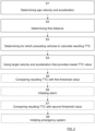
Figure 2-3 show flowcharts for methods according to the present disclosure. -
Figure 1 schematically shows a top view of anego vehicle 1 arranged to run in afirst lane 2a on aroad 2, where theego vehicle 1 comprises avehicle radar system 3. Thevehicle radar system 3 comprises aradar sensor arrangement 4 that is arranged to distinguish and/or resolve targets from the surroundings by transmittingsignal reflected signals signals - In front of the
ego vehicle 1 there is a first precedingtarget vehicle 10, and in front of the first precedingtarget vehicle 10 there is a second precedingtarget vehicle 11, thus preceding the first precedingtarget vehicle 10. - The
vehicle radar system 3 further comprises acontrol unit arrangement 8 that is connected to theradar sensor arrangement 4 and is arranged to provide azimuth angles, distance and radial velocity of possible target object detections by simultaneously sampling and analyzing phase and amplitude of the received signals in a previously well-known manner. Azimuth angles are determined relative aradar reference line 5 that for example is constituted by a radar sensor arrangement boresight direction. - The
control unit arrangement 8 is also arranged to determine vehicle data regarding the own vehicle's, the ego vehicle's, ego velocity v0 and ego acceleration a0. Thecontrol unit arrangement 8 is adapted to acquire these ego vehicle data from suitable sources, such as aspeedometer arrangement 21 and anaccelerometer arrangement 22 comprised in theego vehicle 1 in a previously well-known manner. - In
Figure 1 , afirst radar detection 9 of the first precedingtarget vehicle 10 and asecond radar detection 12 of the second precedingtarget vehicle 11 are shown. Thesecond radar detection 12 is acquired by having corresponding transmittedsignals 7a and receivedreflected signals 7b bounced beneath the first precedingtarget vehicle 10. According to some aspects, the sensorradar sensor arrangement 4 can be tilted vertically to achieve this, but it is also sufficient to have a radar sensor with a sufficient field of view in elevation direction. - According to some aspects, the second radar detection is acquired by having corresponding transmitted signals and received reflected signals reflected at guardrails or other structures along the
road 2. - For reasons of clarity, only one
radar detection target vehicle target vehicle - By means of the
radar detections vehicle radar system 3 is arranged perform tracking of the precedingvehicles - a first distance r1 between the
ego vehicle 1 and the first precedingtarget vehicle 10; - a first target velocity v1 and a first target acceleration a1 for the first preceding
target vehicle 10; - a second distance r2 between the
ego vehicle 1 and the second precedingtarget vehicle 11; and - a second target velocity v2 and a second target acceleration a2 for the second preceding
target vehicle 11. - The
control unit arrangement 8 is arranged to determine the first target acceleration a1 for the first precedingtarget vehicle 10 and the second target acceleration a2 for the second precedingtarget vehicle 11. - According to the present disclosure, the
control unit arrangement 8 is arranged to determine a resulting TTC (time to collision) between theego vehicle 1 and the first precedingtarget vehicle 10, based on the ego velocity v0, the ego acceleration a0, the first distance r1, and those of the target velocity v1, v2 and corresponding target acceleration a1, a2 that provides the lowest value for the resulting TTC. - According to some aspects, the
control unit arrangement 8 is arranged to compare the determined TTC values with a first threshold value and to initiate an alarm if any TTC falls below the first threshold value. Such an alarm is intended to encourage the driver of theego vehicle 1 to react in any suitable way, for example by appropriate steering and/or speed reduction. - According to some aspects, the
control unit arrangement 8 is arranged to compare the determined TTC values with a second threshold value, falling below the first threshold value. If any TTC falls below the second threshold value, thecontrol unit arrangement 8 is arranged to initiate an emergency system such as an automated brake of theego vehicle 1. - For this purpose, as indicated in
Figure 1 , theego vehicle 1 comprises asafety control unit 13 and safety means 14, for example comprising an emergency braking system, seatbelt pretensioners and an alarm signal device. Thesafety control unit 13 is arranged to control the safety means 14 in dependence of input from theradar system 3. Such input may be conferred via thecontrol unit arrangement 8. - According to some aspects, the
control unit arrangement 8 is arranged to determine a corresponding initial TTC between theego vehicle 1 and each one of the precedingvehicles - For this purpose, the
control unit arrangement 8 is arranged to compare the determined initial TTC:s with a TTC threshold, and only preceding vehicles that are associated with a corresponding initial TTC that falls below the TTC threshold are considered when determining the resulting TTC. - According to some aspects, the
control unit arrangement 8 is arranged to compare the determined initial TTC values that fall below the TTC threshold with a first initial threshold value and to initiate an alarm if any of these initial TTC values falls below the initial first threshold value. Such an alarm is intended to encourage the driver of theego vehicle 1 to react in any suitable way, for example by appropriate steering and/or speed reduction. - According to some aspects, the
control unit arrangement 8 is arranged to compare the determined initial TTC values that fall below the TTC threshold with a second initial threshold value, falling below the first initial threshold value. If any of these initial TTC values falls below the second initial threshold value, thecontrol unit arrangement 8 is arranged to initiate an emergency system such as an automated brake of theego vehicle 1. - According to some aspects, the first initial threshold value equals the first threshold value and the second initial threshold value equals the second threshold value.
- According to some aspects, the resulting TTC is determined irrespective of if any determined initial TTC value that falls below the TTC threshold also falls below any threshold value according to the above.
- In this example, the
control unit arrangement 8 is arranged to determine a first initial TTC between theego vehicle 1 and the first precedingtarget vehicle 10 based on the ego velocity v0, the ego acceleration a0, the first distance r1, the first target velocity v1 and the first target acceleration a1. Thecontrol unit arrangement 8 is also arranged to determine a second initial TTC between theego vehicle 1 and the second precedingtarget vehicle 11 based on the ego velocity v0, the ego acceleration a0, the second distance r2 the second target velocity v2 and the second target acceleration a2. - As an illustrating example of the above, if the second preceding
vehicle 11 suddenly brakes and this results in a resulting TTC that falls below the first threshold value or below both the first threshold value and the second threshold value, an alarm or an emergency system should be initiated according to the above. - However, according to some aspects, if the second preceding
vehicle 11 is relatively far away such that the second initial TTC exceeds the TTC threshold, the second precedingvehicle 11 is not considered when the resulting TTC is determined The sudden braking of the second precedingvehicle 11 will consequently not affect the resulting TTC and not initiate any alarm or emergency system. A braking preceding vehicle that is relatively far away from theego vehicle 1 does thus not have any impact on possible safety measures at theego vehicle 1. - The
control unit arrangement 8 is arranged to compare the resulting TTC value with at least one threshold value and to initiate a proper action if any TTC falls below said threshold value. - The present disclosure is also applicable for more than two preceding vehicles, but there are always at least two preceding
vehicles - According to the invention as claimed, for two or more preceding vehicles, for each pair of any two preceding vehicles that travel successively one after the other among said at least two preceding vehicles, the
control unit arrangement 8 is arranged to determine a further TTC between the vehicles in each such pair. Thecontrol unit arrangement 8 is arranged to compare at least one further TTC from said determined further TTC:s with at least one further threshold value, and to adjust at least one of said first threshold value and second threshold value accordingly. - This means that if two preceding vehicles have a relatively low mutual further TTC, at least one of said first threshold value and second threshold value can be temporarily increased, since the risk for collision between these preceding vehicles has increased.
- In order to avoid taking a
target vehicle 30 in asecond lane 2b into account in the above determining of TTC, a path prediction based on the driving state of theego vehicle 1 is performed. Alternatively, a lane detection based on a vision system could be used, or a combination of both. This is independent of in which direction such atarget vehicle 30 is travelling. - With reference to
Figure 2 , the present disclosure also relates to a method for determining TTC, time to collision, between anego vehicle 1 and a closest precedingtarget vehicle 10, where there are at least two precedingtarget vehicles - determining S1 an ego velocity v0 and an ego acceleration a0 for the
ego vehicle 1; - determining S2 a first distance r1 between the
ego vehicle 1 and the closest precedingtarget vehicle 10; and - determining S3 for which preceding vehicles a resulting TTC shall be calculated;
- determining S4 target velocity v1, v2 and corresponding target acceleration a1, a2; and
- using S4 that target velocity v1, v2 and corresponding target acceleration a1, a2 for a
preceding target vehicle target vehicles - With reference also to
Figure 3 , according to some aspects, the determining S3 for which preceding vehicles a resulting TTC shall be calculated comprises: - determining S30 a corresponding distance r2 between the
ego vehicle 1 and each further precedingtarget vehicle 11; - determining S31 an initial TTC between the
ego vehicle 1 and each one of said precedingtarget vehicles - comparing S32 the determined initial TTC:s with a TTC threshold; and
- only considering S33 preceding vehicles that are associated with a corresponding initial TTC that falls below the TTC threshold when determining the resulting TTC.
- According to some aspects, the determining S3 for which preceding vehicles a resulting TTC shall be calculated comprises:
- comparing S34 each initial TTC value that falls below the TTC threshold with a first initial threshold value; and
- initiating S35 an alarm if any of these initial TTC values falls below the first initial threshold value.
- According to some aspects, the determining S3 for which preceding vehicles a resulting TTC shall be calculated comprises:
- comparing S36 each initial TTC value that falls below the TTC threshold with a second initial threshold value, falling below the first initial threshold value; and
- initiating S37 an emergency system if any of these initial TTC values falls below the second initial threshold value.
- According to some aspects, the determining S3 for which preceding vehicles a resulting TTC shall be calculated comprises:
only considering S301 preceding vehicles that are associated with a corresponding initial TTC that falls below the TTC threshold and exceeds all threshold values when determining the resulting TTC. - The method further comprises:
- comparing S5 the resulting TTC with a first threshold value; and
- initiating S6 an alarm if the resulting TTC falls below the first threshold value.
- The method further comprises:
- comparing S7 the resulting TTC with a second threshold value, falling below the first threshold value; and
- initiating S8 an emergency system if the resulting TTC falls below the second threshold value.
- The present disclosure is not limited to the examples above but may vary freely within the scope of the appended claims. For example, the radar system may be implemented in any type of vehicle such as cars, trucks and buses as well as boats and aircraft.
- Exactly how data processing, such as calculations and determining procedures, is accomplished in practice may vary, the example disclosed above is only an example. The
control unit arrangement 8 may be comprised by one or more separate or integrated control units. Thesafety control unit 13 is according to some aspects comprised in thecontrol unit arrangement 8. - In the examples discussed there is a tracked target vehicle; generally, there can be any type of tracked target object such as for example a bicycle or a pedestrian.
- Other kinds of FMCW signals and FMCW signal configurations are also conceivable, as well as other types of Doppler radar signals. Other types of radar systems are also conceivable; not only FMCW radar systems are conceivable. Pulse radar, FSK (frequency-shift keying) or CW (continuous wave) waveform are also conceivable like all other kinds of suitable modulation techniques.
- The present disclosure does not only relate to vehicle radar systems but generally relates to any type of vehicle environment detection system such as ultrasonic or Lidar.
- The present disclosure relates to a vehicle
environment detection system 3 comprising acontrol unit arrangement 8 and at least onesensor arrangement 4 that is arranged to be mounted in anego vehicle 1 and to providesensor detections target vehicles control unit arrangement 8 is arranged to determine a resulting TTC (time to collision) between theego vehicle 1 and a closest precedingtarget vehicle 10, based on an ego velocity v0 and an ego acceleration a0 for theego vehicle 1, a first distance r1 between theego vehicle 1 and the closest precedingtarget vehicle 10, and that target velocity v1, v2 and corresponding target acceleration a1, a2 for apreceding target vehicle target vehicles - According to some aspects, the vehicle
environment detection system 3 is adapted to determine vehicle data regarding an ego velocity v0 and an ego acceleration a0 for theego vehicle 1, and, by means of saidsensor detections ego vehicle 1 and each further precedingtarget vehicle 11, and corresponding target velocity v1, v2 and target acceleration a1, a2 for eachpreceding target vehicle - According to some aspects, the
control unit arrangement 8 is adapted to determine a corresponding initial TTC between theego vehicle 1 and each one of said precedingtarget vehicles - According to some aspects, the
control unit arrangement 8 is arranged to compare each initial TTC value that falls below the TTC threshold with a first initial threshold value and to initiate an alarm if any of these initial TTC values falls below the first initial threshold value. - According to some aspects, the
control unit arrangement 8 is arranged to compare each initial TTC value that falls below the TTC threshold with a second initial threshold value, falling below the first initial threshold value, and to initiate an emergency system if any of these initial TTC values falls below the second initial threshold value. - According to the invention as claimed, the
control unit arrangement 8 is arranged to compare the resulting TTC with a first threshold value and to initiate an alarm if the resulting TTC falls below the first threshold value. - According to the invention as claimed, the
control unit arrangement 8 is arranged to compare the resulting TTC with a second threshold value, falling below the first threshold value, and to initiate an emergency system if the resulting TTC falls below the second threshold value. - According to the invention as claimed, for each pair of any two preceding vehicles that travel successively one after the other among said at least two preceding vehicles, the
control unit arrangement 8 is arranged to determine a corresponding further TTC between the vehicles in each such pair, where thecontrol unit arrangement 8 is arranged to compare at least one further TTC from said determined further TTC:s with at least one further threshold value, and to adjust at least one of said first threshold value and second threshold value accordingly.
Claims (3)
- A vehicle environment detection system (3) , being a radar, ultrasonic or Lidar system, comprising a control unit arrangement (8) and at least one sensor arrangement (4) that is arranged to be mounted in an ego vehicle (1) and to provide sensor detections (9, 12) for at least two preceding target vehicles (10, 11), wherein the control unit arrangement (8) is arranged to determine a resulting TTC, time to collision, between the ego vehicle (1) and the closest preceding target vehicle (10) of the at least two preceding target vehicles, based on an ego velocity (v0) and an ego acceleration (a0) for the ego vehicle (1), a first distance (r1) between the ego vehicle (1) and the closest preceding target vehicle (10), and that target velocity (v1, v2) and corresponding target acceleration (al, a2) for a preceding target vehicle (10, 11) among said target vehicles (10, 11) that provide a lowest TTC value, wherein the control unit arrangement (8) is configured to compare the resulting TTC with a first and second threshold value, the second threshold value falling below the first threshold value, wherein the control unit is configured to initiate an alarm if the resulting TTC falls below the first threshold value and initiate an emergency system if the resulting TTC falls below the second threshold value characterized in that
for each pair of any two preceding vehicles that travel successively one after the other among said at least two preceding vehicles, the control unit arrangement (8) is arranged to determine a corresponding further TTC between the vehicles in each such pair, where the control unit arrangement (8) is arranged to for each pair of vehicles compare the further TTC with a further threshold value, and to adjust at least one of a first and second threshold value accordingly. - The vehicle environment detection system (3) according to claim 1, wherein the vehicle environment detection system (3) is adapted to determine vehicle data regarding an ego velocity (v0) and an ego acceleration (a0) for the ego vehicle (1), and, by means of said sensor detections (9, 12), to determine further vehicle data comprising the first distance (r1) and a corresponding distance (r2) between the ego vehicle (1) and each further preceding target vehicle (11), and corresponding target velocity (v1, v2) and target acceleration (a2) for each preceding target vehicle (10, 11).
- A method for determining TTC, time to collision,between an ego vehicle (1) and a closest preceding target vehicle (10), where there are at least two preceding target vehicles (10, 11), the method, utilizing a detection system (3) being a radar,
ultrasonic or Lidar system, comprising:determining (S1) an ego velocity (v0) and an ego acceleration (a0) for the ego vehicle (1);determining (S2) a first distance (r1) between the ego vehicle (1) and the closest preceding target vehicle (10); and determining (S3) for which preceding vehicles a resulting TTC shall be calculated;for each one of the preceding vehicles for which the resulting TTC shall be calculated, the method further comprises:
determining (S4) target velocity (v1), andcorresponding target acceleration (al, a2); andusing (S4) that target velocity (v1, v1) and corresponding target acceleration (al, a2) for a preceding target vehicle (10, 11), among said target vehicles (10, 11), that provide the lowest TTC value, wherein the control unit arrangement (8) is configured to compare the resulting TTC with a first and second threshold value, the second threshold value falling below the first threshold value, wherein the control unit is configured to initiate an alarm if the resulting TTC falls below the first threshold value and initiate an emergency system if the resulting TTC falls below the second threshold valuecharacterized in thatthe method further comprises determining, for each pair of any two preceding vehicles that travel successively one after the other among said at least two preceding vehicles, a corresponding further TTC between the vehicles in each such pair, comparing for each pair of vehicles the further TTC with a further threshold value, and adjusting at least one of the first and second threshold values accordingly.
Priority Applications (3)
| Application Number | Priority Date | Filing Date | Title |
|---|---|---|---|
| EP19158200.6A EP3699632B8 (en) | 2019-02-20 | 2019-02-20 | A vehicle radar system for detecting preceding objects |
| PCT/EP2020/054169 WO2020169561A1 (en) | 2019-02-20 | 2020-02-18 | A vehicle radar system for detecting preceding objects |
| US17/432,207 US12411231B2 (en) | 2019-02-20 | 2020-02-18 | Vehicle radar system for detecting preceding objects |
Applications Claiming Priority (1)
| Application Number | Priority Date | Filing Date | Title |
|---|---|---|---|
| EP19158200.6A EP3699632B8 (en) | 2019-02-20 | 2019-02-20 | A vehicle radar system for detecting preceding objects |
Publications (3)
| Publication Number | Publication Date |
|---|---|
| EP3699632A1 EP3699632A1 (en) | 2020-08-26 |
| EP3699632B1 true EP3699632B1 (en) | 2024-12-25 |
| EP3699632B8 EP3699632B8 (en) | 2025-02-19 |
Family
ID=65657214
Family Applications (1)
| Application Number | Title | Priority Date | Filing Date |
|---|---|---|---|
| EP19158200.6A Active EP3699632B8 (en) | 2019-02-20 | 2019-02-20 | A vehicle radar system for detecting preceding objects |
Country Status (3)
| Country | Link |
|---|---|
| US (1) | US12411231B2 (en) |
| EP (1) | EP3699632B8 (en) |
| WO (1) | WO2020169561A1 (en) |
Families Citing this family (3)
| Publication number | Priority date | Publication date | Assignee | Title |
|---|---|---|---|---|
| FR3117978B1 (en) * | 2020-12-17 | 2022-12-23 | Psa Automobiles Sa | Method and device for regulating the speed of an autonomous vehicle. |
| DE102022112104A1 (en) * | 2022-05-13 | 2023-11-16 | Zf Cv Systems Global Gmbh | Method and device for preventing an ego vehicle from colliding with a vehicle in front, as well as vehicle and electronic processing unit |
| JP7784364B2 (en) * | 2022-09-20 | 2025-12-11 | 本田技研工業株式会社 | Attention warning system and attention warning method |
Family Cites Families (8)
| Publication number | Priority date | Publication date | Assignee | Title |
|---|---|---|---|---|
| JP4513662B2 (en) | 2005-06-15 | 2010-07-28 | 株式会社デンソー | In-vehicle radar device, vehicle control system |
| JP2009157472A (en) * | 2007-12-25 | 2009-07-16 | Mitsubishi Fuso Truck & Bus Corp | Collision damage reduction device for vehicle |
| US8527172B2 (en) * | 2010-10-20 | 2013-09-03 | GM Global Technology Operations LLC | Vehicle collision avoidance and warning system |
| US9633565B2 (en) * | 2012-11-15 | 2017-04-25 | GM Global Technology Operations LLC | Active safety system and method for operating the same |
| DE102013214233B4 (en) | 2013-07-19 | 2015-02-05 | Honda Motor Co., Ltd. | Intelligent forward collision warning system |
| JP6299208B2 (en) * | 2013-12-26 | 2018-03-28 | トヨタ自動車株式会社 | Vehicle surrounding situation estimation device |
| JP6361666B2 (en) * | 2016-01-26 | 2018-07-25 | トヨタ自動車株式会社 | Vehicle collision avoidance support system |
| JP6972744B2 (en) * | 2017-08-01 | 2021-11-24 | トヨタ自動車株式会社 | Driving support device |
-
2019
- 2019-02-20 EP EP19158200.6A patent/EP3699632B8/en active Active
-
2020
- 2020-02-18 WO PCT/EP2020/054169 patent/WO2020169561A1/en not_active Ceased
- 2020-02-18 US US17/432,207 patent/US12411231B2/en active Active
Also Published As
| Publication number | Publication date |
|---|---|
| US12411231B2 (en) | 2025-09-09 |
| EP3699632B8 (en) | 2025-02-19 |
| WO2020169561A1 (en) | 2020-08-27 |
| US20220187449A1 (en) | 2022-06-16 |
| EP3699632A1 (en) | 2020-08-26 |
Similar Documents
| Publication | Publication Date | Title |
|---|---|---|
| EP3539837B1 (en) | A vehicle radar system for detecting preceding vehicles | |
| EP3208165B1 (en) | Vehicle safety assist system | |
| US11731614B2 (en) | Apparatus and method for controlling vehicle to avoid or mitigate collision | |
| US10661792B2 (en) | System and method for performing autonomous emergency braking | |
| CN111137281B (en) | Vehicle and control method for vehicle | |
| EP2302412B1 (en) | System and method for evaluation of an automotive vehicle forward collision threat | |
| CA3011957C (en) | Driving assistance system | |
| EP3254918B1 (en) | Adaptive cruise control system and vehicle comprising an adaptive cruise control system | |
| US8615357B2 (en) | Method for assisting a user of a vehicle, control device for a driver-assistance system of a vehicle and vehicle having such a control device | |
| US9682689B2 (en) | Emergency braking system for a vehicle | |
| US11427166B2 (en) | Adaptive AEB system considering steerable path and control method thereof | |
| EP2484573B1 (en) | Method for reducing the risk of a collision between a vehicle and a first external object | |
| US9886858B2 (en) | Lane change detection | |
| EP1956574A2 (en) | Collision avoidance system | |
| US9771055B1 (en) | Front impact mitigation system for a vehicle and method | |
| KR101384710B1 (en) | Method for speed regulation of a motor vehicle in a complex traffic situation | |
| US12411231B2 (en) | Vehicle radar system for detecting preceding objects | |
| US7715275B2 (en) | Start assist system for motor vehicles | |
| JP2020083087A (en) | Driving support system | |
| KR20190011630A (en) | Smart cruise control apparatus and method with rear impact mitigation function | |
| JP7769304B2 (en) | Collision prevention device, collision prevention method, and collision prevention program | |
| CN120840609A (en) | Control method and device of adaptive cruise control system ACC | |
| KR20260043238A (en) | Driver assistance method and driver assistance system for preventing forward collision |
Legal Events
| Date | Code | Title | Description |
|---|---|---|---|
| PUAI | Public reference made under article 153(3) epc to a published international application that has entered the european phase |
Free format text: ORIGINAL CODE: 0009012 |
|
| STAA | Information on the status of an ep patent application or granted ep patent |
Free format text: STATUS: THE APPLICATION HAS BEEN PUBLISHED |
|
| AK | Designated contracting states |
Kind code of ref document: A1 Designated state(s): AL AT BE BG CH CY CZ DE DK EE ES FI FR GB GR HR HU IE IS IT LI LT LU LV MC MK MT NL NO PL PT RO RS SE SI SK SM TR |
|
| AX | Request for extension of the european patent |
Extension state: BA ME |
|
| STAA | Information on the status of an ep patent application or granted ep patent |
Free format text: STATUS: REQUEST FOR EXAMINATION WAS MADE |
|
| 17P | Request for examination filed |
Effective date: 20210225 |
|
| RBV | Designated contracting states (corrected) |
Designated state(s): AL AT BE BG CH CY CZ DE DK EE ES FI FR GB GR HR HU IE IS IT LI LT LU LV MC MK MT NL NO PL PT RO RS SE SI SK SM TR |
|
| RAP1 | Party data changed (applicant data changed or rights of an application transferred) |
Owner name: ARRIVER SOFTWARE AB |
|
| STAA | Information on the status of an ep patent application or granted ep patent |
Free format text: STATUS: EXAMINATION IS IN PROGRESS |
|
| 17Q | First examination report despatched |
Effective date: 20230119 |
|
| REG | Reference to a national code |
Ref country code: DE Ref legal event code: R079 Ref document number: 602019063862 Country of ref document: DE Free format text: PREVIOUS MAIN CLASS: G01S0013520000 Ipc: G01S0013931000 |
|
| GRAP | Despatch of communication of intention to grant a patent |
Free format text: ORIGINAL CODE: EPIDOSNIGR1 |
|
| STAA | Information on the status of an ep patent application or granted ep patent |
Free format text: STATUS: GRANT OF PATENT IS INTENDED |
|
| RIC1 | Information provided on ipc code assigned before grant |
Ipc: B60W 50/14 20200101ALN20240703BHEP Ipc: G01S 13/58 20060101ALN20240703BHEP Ipc: B60W 30/17 20200101ALI20240703BHEP Ipc: B60W 30/095 20120101ALI20240703BHEP Ipc: G01S 7/41 20060101ALI20240703BHEP Ipc: G01S 13/52 20060101ALI20240703BHEP Ipc: B60W 30/16 20200101ALI20240703BHEP Ipc: G01S 13/72 20060101ALI20240703BHEP Ipc: G01S 13/931 20200101AFI20240703BHEP |
|
| INTG | Intention to grant announced |
Effective date: 20240715 |
|
| RIC1 | Information provided on ipc code assigned before grant |
Ipc: B60W 50/14 20200101ALN20240708BHEP Ipc: G01S 13/58 20060101ALN20240708BHEP Ipc: B60W 30/17 20200101ALI20240708BHEP Ipc: B60W 30/095 20120101ALI20240708BHEP Ipc: G01S 7/41 20060101ALI20240708BHEP Ipc: G01S 13/52 20060101ALI20240708BHEP Ipc: B60W 30/16 20200101ALI20240708BHEP Ipc: G01S 13/72 20060101ALI20240708BHEP Ipc: G01S 13/931 20200101AFI20240708BHEP |
|
| GRAS | Grant fee paid |
Free format text: ORIGINAL CODE: EPIDOSNIGR3 |
|
| GRAA | (expected) grant |
Free format text: ORIGINAL CODE: 0009210 |
|
| STAA | Information on the status of an ep patent application or granted ep patent |
Free format text: STATUS: THE PATENT HAS BEEN GRANTED |
|
| REG | Reference to a national code |
Ref country code: DE Ref legal event code: R081 Ref document number: 602019063862 Country of ref document: DE Owner name: QUALCOMM AUTO LTD., GB Free format text: FORMER OWNER: ARRIVER SOFTWARE AB, LINKOEPING, SE |
|
| AK | Designated contracting states |
Kind code of ref document: B1 Designated state(s): AL AT BE BG CH CY CZ DE DK EE ES FI FR GB GR HR HU IE IS IT LI LT LU LV MC MK MT NL NO PL PT RO RS SE SI SK SM TR |
|
| REG | Reference to a national code |
Ref country code: GB Ref legal event code: FG4D |
|
| REG | Reference to a national code |
Ref country code: CH Ref legal event code: EP |
|
| RAP2 | Party data changed (patent owner data changed or rights of a patent transferred) |
Owner name: QUALCOMM AUTO LTD. |
|
| REG | Reference to a national code |
Ref country code: DE Ref legal event code: R096 Ref document number: 602019063862 Country of ref document: DE |
|
| REG | Reference to a national code |
Ref country code: IE Ref legal event code: FG4D |
|
| REG | Reference to a national code |
Ref country code: CH Ref legal event code: PK Free format text: BERICHTIGUNG B8 |
|
| REG | Reference to a national code |
Ref country code: LT Ref legal event code: MG9D |
|
| PG25 | Lapsed in a contracting state [announced via postgrant information from national office to epo] |
Ref country code: HR Free format text: LAPSE BECAUSE OF FAILURE TO SUBMIT A TRANSLATION OF THE DESCRIPTION OR TO PAY THE FEE WITHIN THE PRESCRIBED TIME-LIMIT Effective date: 20241225 |
|
| PGFP | Annual fee paid to national office [announced via postgrant information from national office to epo] |
Ref country code: DE Payment date: 20250326 Year of fee payment: 7 |
|
| PG25 | Lapsed in a contracting state [announced via postgrant information from national office to epo] |
Ref country code: FI Free format text: LAPSE BECAUSE OF FAILURE TO SUBMIT A TRANSLATION OF THE DESCRIPTION OR TO PAY THE FEE WITHIN THE PRESCRIBED TIME-LIMIT Effective date: 20241225 |
|
| PG25 | Lapsed in a contracting state [announced via postgrant information from national office to epo] |
Ref country code: BG Free format text: LAPSE BECAUSE OF FAILURE TO SUBMIT A TRANSLATION OF THE DESCRIPTION OR TO PAY THE FEE WITHIN THE PRESCRIBED TIME-LIMIT Effective date: 20241225 |
|
| PG25 | Lapsed in a contracting state [announced via postgrant information from national office to epo] |
Ref country code: NO Free format text: LAPSE BECAUSE OF FAILURE TO SUBMIT A TRANSLATION OF THE DESCRIPTION OR TO PAY THE FEE WITHIN THE PRESCRIBED TIME-LIMIT Effective date: 20250325 |
|
| PG25 | Lapsed in a contracting state [announced via postgrant information from national office to epo] |
Ref country code: LV Free format text: LAPSE BECAUSE OF FAILURE TO SUBMIT A TRANSLATION OF THE DESCRIPTION OR TO PAY THE FEE WITHIN THE PRESCRIBED TIME-LIMIT Effective date: 20241225 Ref country code: GR Free format text: LAPSE BECAUSE OF FAILURE TO SUBMIT A TRANSLATION OF THE DESCRIPTION OR TO PAY THE FEE WITHIN THE PRESCRIBED TIME-LIMIT Effective date: 20250326 |
|
| PG25 | Lapsed in a contracting state [announced via postgrant information from national office to epo] |
Ref country code: RS Free format text: LAPSE BECAUSE OF FAILURE TO SUBMIT A TRANSLATION OF THE DESCRIPTION OR TO PAY THE FEE WITHIN THE PRESCRIBED TIME-LIMIT Effective date: 20250325 |
|
| REG | Reference to a national code |
Ref country code: NL Ref legal event code: MP Effective date: 20241225 |
|
| PG25 | Lapsed in a contracting state [announced via postgrant information from national office to epo] |
Ref country code: NL Free format text: LAPSE BECAUSE OF FAILURE TO SUBMIT A TRANSLATION OF THE DESCRIPTION OR TO PAY THE FEE WITHIN THE PRESCRIBED TIME-LIMIT Effective date: 20241225 |
|
| REG | Reference to a national code |
Ref country code: AT Ref legal event code: MK05 Ref document number: 1754625 Country of ref document: AT Kind code of ref document: T Effective date: 20241225 |
|
| PG25 | Lapsed in a contracting state [announced via postgrant information from national office to epo] |
Ref country code: SM Free format text: LAPSE BECAUSE OF FAILURE TO SUBMIT A TRANSLATION OF THE DESCRIPTION OR TO PAY THE FEE WITHIN THE PRESCRIBED TIME-LIMIT Effective date: 20241225 |
|
| PG25 | Lapsed in a contracting state [announced via postgrant information from national office to epo] |
Ref country code: PL Free format text: LAPSE BECAUSE OF FAILURE TO SUBMIT A TRANSLATION OF THE DESCRIPTION OR TO PAY THE FEE WITHIN THE PRESCRIBED TIME-LIMIT Effective date: 20241225 |
|
| PG25 | Lapsed in a contracting state [announced via postgrant information from national office to epo] |
Ref country code: ES Free format text: LAPSE BECAUSE OF FAILURE TO SUBMIT A TRANSLATION OF THE DESCRIPTION OR TO PAY THE FEE WITHIN THE PRESCRIBED TIME-LIMIT Effective date: 20241225 |
|
| PG25 | Lapsed in a contracting state [announced via postgrant information from national office to epo] |
Ref country code: IS Free format text: LAPSE BECAUSE OF FAILURE TO SUBMIT A TRANSLATION OF THE DESCRIPTION OR TO PAY THE FEE WITHIN THE PRESCRIBED TIME-LIMIT Effective date: 20250425 |
|
| PG25 | Lapsed in a contracting state [announced via postgrant information from national office to epo] |
Ref country code: PT Free format text: LAPSE BECAUSE OF FAILURE TO SUBMIT A TRANSLATION OF THE DESCRIPTION OR TO PAY THE FEE WITHIN THE PRESCRIBED TIME-LIMIT Effective date: 20250428 |
|
| PG25 | Lapsed in a contracting state [announced via postgrant information from national office to epo] |
Ref country code: RO Free format text: LAPSE BECAUSE OF FAILURE TO SUBMIT A TRANSLATION OF THE DESCRIPTION OR TO PAY THE FEE WITHIN THE PRESCRIBED TIME-LIMIT Effective date: 20241225 Ref country code: AT Free format text: LAPSE BECAUSE OF FAILURE TO SUBMIT A TRANSLATION OF THE DESCRIPTION OR TO PAY THE FEE WITHIN THE PRESCRIBED TIME-LIMIT Effective date: 20241225 |
|
| PG25 | Lapsed in a contracting state [announced via postgrant information from national office to epo] |
Ref country code: SK Free format text: LAPSE BECAUSE OF FAILURE TO SUBMIT A TRANSLATION OF THE DESCRIPTION OR TO PAY THE FEE WITHIN THE PRESCRIBED TIME-LIMIT Effective date: 20241225 |
|
| PG25 | Lapsed in a contracting state [announced via postgrant information from national office to epo] |
Ref country code: CZ Free format text: LAPSE BECAUSE OF FAILURE TO SUBMIT A TRANSLATION OF THE DESCRIPTION OR TO PAY THE FEE WITHIN THE PRESCRIBED TIME-LIMIT Effective date: 20241225 |
|
| PG25 | Lapsed in a contracting state [announced via postgrant information from national office to epo] |
Ref country code: IT Free format text: LAPSE BECAUSE OF FAILURE TO SUBMIT A TRANSLATION OF THE DESCRIPTION OR TO PAY THE FEE WITHIN THE PRESCRIBED TIME-LIMIT Effective date: 20241225 |
|
| PG25 | Lapsed in a contracting state [announced via postgrant information from national office to epo] |
Ref country code: SE Free format text: LAPSE BECAUSE OF FAILURE TO SUBMIT A TRANSLATION OF THE DESCRIPTION OR TO PAY THE FEE WITHIN THE PRESCRIBED TIME-LIMIT Effective date: 20241225 |
|
| PG25 | Lapsed in a contracting state [announced via postgrant information from national office to epo] |
Ref country code: MC Free format text: LAPSE BECAUSE OF FAILURE TO SUBMIT A TRANSLATION OF THE DESCRIPTION OR TO PAY THE FEE WITHIN THE PRESCRIBED TIME-LIMIT Effective date: 20241225 |
|
| REG | Reference to a national code |
Ref country code: DE Ref legal event code: R097 Ref document number: 602019063862 Country of ref document: DE |
|
| REG | Reference to a national code |
Ref country code: CH Ref legal event code: PL |
|
| PG25 | Lapsed in a contracting state [announced via postgrant information from national office to epo] |
Ref country code: DK Free format text: LAPSE BECAUSE OF FAILURE TO SUBMIT A TRANSLATION OF THE DESCRIPTION OR TO PAY THE FEE WITHIN THE PRESCRIBED TIME-LIMIT Effective date: 20241225 |
|
| PG25 | Lapsed in a contracting state [announced via postgrant information from national office to epo] |
Ref country code: LU Free format text: LAPSE BECAUSE OF NON-PAYMENT OF DUE FEES Effective date: 20250220 |
|
| PG25 | Lapsed in a contracting state [announced via postgrant information from national office to epo] |
Ref country code: CH Free format text: LAPSE BECAUSE OF NON-PAYMENT OF DUE FEES Effective date: 20250228 |
|
| PLBE | No opposition filed within time limit |
Free format text: ORIGINAL CODE: 0009261 |
|
| STAA | Information on the status of an ep patent application or granted ep patent |
Free format text: STATUS: NO OPPOSITION FILED WITHIN TIME LIMIT |
|
| 26N | No opposition filed |
Effective date: 20250926 |
|
| REG | Reference to a national code |
Ref country code: BE Ref legal event code: MM Effective date: 20250228 |
|
| PG25 | Lapsed in a contracting state [announced via postgrant information from national office to epo] |
Ref country code: BE Free format text: LAPSE BECAUSE OF NON-PAYMENT OF DUE FEES Effective date: 20250228 |
|
| PG25 | Lapsed in a contracting state [announced via postgrant information from national office to epo] |
Ref country code: IE Free format text: LAPSE BECAUSE OF NON-PAYMENT OF DUE FEES Effective date: 20250220 |
|
| PGFP | Annual fee paid to national office [announced via postgrant information from national office to epo] |
Ref country code: GB Payment date: 20260113 Year of fee payment: 8 |
|
| PGFP | Annual fee paid to national office [announced via postgrant information from national office to epo] |
Ref country code: FR Payment date: 20260109 Year of fee payment: 8 |