EP3699601A1 - Reaction method - Google Patents
Reaction method Download PDFInfo
- Publication number
- EP3699601A1 EP3699601A1 EP18869352.7A EP18869352A EP3699601A1 EP 3699601 A1 EP3699601 A1 EP 3699601A1 EP 18869352 A EP18869352 A EP 18869352A EP 3699601 A1 EP3699601 A1 EP 3699601A1
- Authority
- EP
- European Patent Office
- Prior art keywords
- pipette tip
- preset temperature
- pipette
- distal end
- end position
- Prior art date
- Legal status (The legal status is an assumption and is not a legal conclusion. Google has not performed a legal analysis and makes no representation as to the accuracy of the status listed.)
- Granted
Links
Images




Classifications
-
- B—PERFORMING OPERATIONS; TRANSPORTING
- B01—PHYSICAL OR CHEMICAL PROCESSES OR APPARATUS IN GENERAL
- B01L—CHEMICAL OR PHYSICAL LABORATORY APPARATUS FOR GENERAL USE
- B01L3/00—Containers or dishes for laboratory use, e.g. laboratory glassware; Droppers
- B01L3/02—Burettes; Pipettes
- B01L3/021—Pipettes, i.e. with only one conduit for withdrawing and redistributing liquids
-
- B—PERFORMING OPERATIONS; TRANSPORTING
- B01—PHYSICAL OR CHEMICAL PROCESSES OR APPARATUS IN GENERAL
- B01L—CHEMICAL OR PHYSICAL LABORATORY APPARATUS FOR GENERAL USE
- B01L3/00—Containers or dishes for laboratory use, e.g. laboratory glassware; Droppers
- B01L3/02—Burettes; Pipettes
- B01L3/0275—Interchangeable or disposable dispensing tips
-
- B—PERFORMING OPERATIONS; TRANSPORTING
- B01—PHYSICAL OR CHEMICAL PROCESSES OR APPARATUS IN GENERAL
- B01L—CHEMICAL OR PHYSICAL LABORATORY APPARATUS FOR GENERAL USE
- B01L7/00—Heating or cooling apparatus; Heat insulating devices
-
- G—PHYSICS
- G01—MEASURING; TESTING
- G01N—INVESTIGATING OR ANALYSING MATERIALS BY DETERMINING THEIR CHEMICAL OR PHYSICAL PROPERTIES
- G01N1/00—Sampling; Preparing specimens for investigation
-
- G—PHYSICS
- G01—MEASURING; TESTING
- G01N—INVESTIGATING OR ANALYSING MATERIALS BY DETERMINING THEIR CHEMICAL OR PHYSICAL PROPERTIES
- G01N35/00—Automatic analysis not limited to methods or materials provided for in any single one of groups G01N1/00 - G01N33/00; Handling materials therefor
- G01N35/10—Devices for transferring samples or any liquids to, in, or from, the analysis apparatus, e.g. suction devices, injection devices
-
- B—PERFORMING OPERATIONS; TRANSPORTING
- B01—PHYSICAL OR CHEMICAL PROCESSES OR APPARATUS IN GENERAL
- B01L—CHEMICAL OR PHYSICAL LABORATORY APPARATUS FOR GENERAL USE
- B01L2200/00—Solutions for specific problems relating to chemical or physical laboratory apparatus
- B01L2200/14—Process control and prevention of errors
- B01L2200/143—Quality control, feedback systems
- B01L2200/147—Employing temperature sensors
-
- B—PERFORMING OPERATIONS; TRANSPORTING
- B01—PHYSICAL OR CHEMICAL PROCESSES OR APPARATUS IN GENERAL
- B01L—CHEMICAL OR PHYSICAL LABORATORY APPARATUS FOR GENERAL USE
- B01L2300/00—Additional constructional details
- B01L2300/18—Means for temperature control
- B01L2300/1805—Conductive heating, heat from thermostatted solids is conducted to receptacles, e.g. heating plates, blocks
-
- B—PERFORMING OPERATIONS; TRANSPORTING
- B01—PHYSICAL OR CHEMICAL PROCESSES OR APPARATUS IN GENERAL
- B01L—CHEMICAL OR PHYSICAL LABORATORY APPARATUS FOR GENERAL USE
- B01L2300/00—Additional constructional details
- B01L2300/18—Means for temperature control
- B01L2300/1805—Conductive heating, heat from thermostatted solids is conducted to receptacles, e.g. heating plates, blocks
- B01L2300/1827—Conductive heating, heat from thermostatted solids is conducted to receptacles, e.g. heating plates, blocks using resistive heater
Definitions
- the present invention relates to a reaction method that involves a reaction process of allowing two or more substances to cause a reaction by using a pipette tip for drawing and ejecting liquid attached to a pipette nozzle.
- a pipette nozzle and a pipette tip attached to the tip thereof are used for highly sensitive and quantitative detection of a trace amount of target substance such as a protein or a DNA.
- target substance such as a protein or a DNA.
- a pipette tip is used for supplying and removing a sample and a labeling liquid.
- a method described in Patent Document 2 involves correcting the distal end position of the pipette tip on the basis of the estimated temperature at the time of the reaction process or on the basis of the temperature of the pipette tip measured at the time of the reaction process, so as to control the distal end position of the pipette tip with respect to the bottom surface a flow path at the time of feeding or suctioning a liquid.
- Patent Document 2 a problem with the method described in Patent Document 2 is that when the distal end position of the pipette is corrected based on the estimated temperature at the time of the reaction process, a deviation may occur depending on ambient temperature.
- the distal end position of the pipette is corrected based on the temperature of the pipette tip measured at the time of the reaction process, it is necessary to provide a means for measuring the temperature of the pipette tip.
- it is complicated to correct and control the distal end position the pipette tip during the reaction process regardless of whether the control is based on the estimated temperature or the measured temperature.
- the present invention has been made in view of the above-described problems in the prior art, and it is an object of the present invention to provide a reaction method capable of accurately and quickly detecting before a reaction process the distal end position of a pipette tip during the reaction process.
- the invention of claim 1 is a reaction method that includes a reaction process of supplying and removing a liquid to and from a reaction site multiple times by using a pipette tip for drawing and ejecting a liquid attached to a pipette nozzle so as to allow two or more substances to cause a reaction, the method comprising:
- the invention of claim 2 is the reaction method according to claim 1, wherein the pipette tip is made of a resin, and a linear expansion coefficient of the pipette tip is equal to or greater than 5.8 ⁇ 10 -5 /°C.
- the invention of claim 3 is the reaction method according to claim 1 or 2, wherein the first preset temperature is 10°C to 15°C higher than the second preset temperature.
- the present invention of claim 4 is the reaction method according to claim 1 or 2 or 3, wherein the preset period is from 5 s to 10 s.
- the present invention of claim 5 is the reaction method according to any one of claims 1 to 4, wherein the distal end position of the pipette tip is detected 10 s to 20 s after the switching to the second preset temperature, and the reaction process is executed while controlling the distal end position of the pipette tip by controlling movement of the pipette nozzle with reference to the detected distal end position.
- the distal end position of the pipette tip is detected before the reaction process. Since the temperature of the pipette tip is maintained by the second preset temperature at the time of detection of the distal end position of the pipette tip and during the reaction process, the distal end position of the pipette tip during the reaction process can be accurately detected before the reaction process. Further, since there is a period of heating the pipette tip by the first preset temperature that is higher than the second preset temperature, the temperature can converge early after switching to the second preset temperature. Therefore, it is possible to detect the distal end position of the pipette tip shortly after the attachment of the pipette tip or the start of heating by the heater.
- a reaction method includes a reaction process of supplying and removing a liquid to and from a reaction site multiple times by using a pipette tip for drawing and ejecting a liquid attached to a pipette nozzle, so as to allow two or more substances to cause a reaction.
- a pipette tip 2 is attached to a tip portion of a pipette nozzle 1.
- the heater 3 is disposed close to the attaching position of the pipette tip 2 ahead of the tip of the pipette nozzle 1.
- the heater 3 is configured to heat the pipette tip 2 attached to the pipette nozzle 1.
- the control device 10 controls the operation of an analyzer that performs the reaction method of the present embodiment.
- the control device 10 controls movement in the axial direction Z of the pipette nozzle 1 by the nozzle movement actuator 11, so as to control the level of the distal end of the pipette tip 2 with respect to the bottom surface 21 of a flow path of a detection chip 20.
- the control device 10 controls the output of the heater 3 via the heater driving circuit 12.
- the control device 10 controls a distal end position detecting means 13 to detect the distal end position in the axial direction Z of the pipette tip 2, so as to obtain the Z-coordinate thereof.
- the distal end position detecting means 13 may be constituted by an optical sensor as described in Patent Document 1 or may be configured to measure the air pressure from the pipette tip 2 as described in Patent Document 2.
- the present invention is not limited with regard to the means or method for detecting the distal end position of the pipette tip 2.
- the linear expansion coefficient of the pipette tip 2 depends on the material of the pipette tip 2.
- the pipette tip 2 is preferably made of resin since such pipette tips can be produced readily at low cost.
- the linear expansion coefficient thereof ranges roughly from 5.8 ⁇ 10 -5 to 12 ⁇ 10 -5 /°C.
- the linear expansion coefficients thereof ranges roughly from 6.0 ⁇ 10 -5 to 8.0 ⁇ 10 -5 /°C.
- the linear expansion coefficient ranges roughly from 11 ⁇ 10 -5 to 15 ⁇ 10 -5 /°C.
- the line expansion coefficient thereof ranges roughly from is 16 ⁇ 10 -5 to 20 ⁇ 10 -5 /°C. Further, when the pipette chip 2 is made of fluororesin, the linear expansion coefficient thereof ranges roughly from 10 ⁇ 10 -5 to 12 ⁇ 10 -5 /°C.
- the control device 10 and the heater driving circuit 12 are configured to drive the heater 3 at a first preset temperature or a second preset temperature.
- the second preset temperature which is used during the reaction process, is determined according to the type of the reaction.
- the first preset temperature is used for preheating.
- the first preset temperature is higher than the second preset temperature.
- the pipette tip 2 is attached to the pipette nozzle 1.
- the output of the heater 3 is adjusted to the first preset temperature. This is because the method can proceed to a reaction process in a short time.
- Step S1 the pipette tip 2 starts to be heated by the first preset temperature of the heater 3 (Step S1).
- Step S3 When the heating time of the pipette tip 2 by the first preset temperature exceeds a first preset period (Yes in Step S2), the output of the heater 3 is switched to the second preset temperature so that the temperature of the pipette tip is kept by the second preset temperature (Step S3). The output of the heater 3 is maintained at a second preset temperature.
- the distal end position of the pipette tip 2 is detected by the distal end position detecting means 13 at or after switching to the second preset temperature.
- a second preset period starts from the time of switching to the second preset temperature. That is, when the second preset period has elapsed (Yes in Step S4), the distal end position of the pipette tip 2 is detected by the distal end position detecting means 13. If the second preset period is 0, the distal end position of the pipette tip 2 is detected at the time of switching to the second preset temperature. If the second preset period is 10 s, the distal end position of the pipette tip 2 is detected 10 s after switching to the second preset temperature.
- Step S6 the nozzle movement actuator 11 is controlled to control the movement of the pipette nozzle 1 in the axial direction so as to control the distal end position of the pipette tip 2 while the reaction process is executed (Step S6).
- a liquid is ejected through the distal end opening of the pipette tip 2 to the detection chip 20, or a liquid is drawn from the detection chip 20 through the distal end opening of the pipette tip 2.
- the level of the distal end of the pipette tip 2 with respect to the bottom surface 21 of the flow path of the detection chip 20 is suitably controlled with reference to the distal end position detected in Step S5 so that the ejection and draw are correctly performed.
- Step S3 After switching to the second preset temperature in Step S3, the output is maintained at the second preset temperature until this point. However, it is only necessary to continue heating the pipette tip 2 by the second preset temperature of the heater 3 at least until an operation using the pipette tip 2 in the reaction process. This is because it is not necessary to heat the pipette tip 2 any more after the operation using the pipette tip 2 is completed.
- the first preset temperature is 10°C to 15°C higher than the second preset temperature
- the first preset period is from 5 s to 10 s
- the second preset temperature is from 10 s to 20 s.
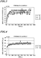
- FIG. 3 to FIG. 14 are graphs showing the change of the distal end position of the pipette tip 2 in the axial Z direction over time.
- FIG. 3 to FIG. 8 represent comparative examples
- FIG. 9 to FIG. 14 represent inventive examples.
- the distal end of the pipette tip 2 was detected at regular time intervals.
- N1, N2 and N3 in the graphs represent different samples of the pipette tip 2.
- the heater 3 is maintained at a constant preset temperature.
- the point when the pipette tip 2 is attached to the pipette nozzle 1, that is, the point when the heating by the heater 3 is started is represented by "0" on the time axis, which is the horizontal axis of each graph.
- the output of the heater 3 is changed from the first preset temperature to the second preset temperature.
- the point of switching to the second preset temperature is represented by "0" on the time axis, which is the horizontal axis of each graph.
- Comparative Example 1 shown in FIG. 3 the preset temperature is 40°C, and the ambient temperature is 10°C.
- the preset temperature is 40°C.
- the ambient temperature is 23°C.
- the preset temperature is 40°C
- the ambient temperature is 30°C.
- Comparative Example 5 shown in FIG. 7 the preset temperature is 45°C, and the ambient temperature is 23°C.
- the preset temperature is 45°C
- the ambient temperature is 30°C.
- the first preset temperature is 50°C
- the first preset period is 5 s
- the second preset temperature is 40°C
- the ambient temperature is 10°C.
- the first preset temperature is 50°C
- the first preset period is 5 s
- the second preset temperature is 40°C
- the ambient temperature is 23°C.
- the first preset temperature is 50°C
- the first preset period is 5 s
- the second preset temperature is 40°C
- the ambient temperature is 30°C.
- the first preset temperature is 50°C
- the first preset period is 10 s
- the second preset temperature is 40°C
- the ambient temperature is 10°C.
- the first preset temperature is 50°C
- the first preset period is 10 s
- the second preset temperature is 40°C
- the ambient temperature is 23°C.
- the first preset temperature is 50°C
- the first preset period is 10 s
- the second preset temperature is 40°C
- the ambient temperature is 30°C.
- the point (Tc) when the variation converges within the range of a convergence point ⁇ 10 ⁇ m was calculated as the average of multiple samples and shown in each graph and table I.
- the convergence point was the average value of the data from the last 10 points.
- Table I values obtained by adding the first preset times are also shown for the inventive examples.
- the temperature of the pipette tip is maintained by the second preset temperature at the time of detecting the distal end position of the pipette tip 2 and during the reaction process. Therefore, it is possible to accurately detect the distal end position of the pipette tip during the reaction process before the reaction process.
- a heating period at the first preset temperature is set as a high-temperature preheating period so that the pipette tip 2 is rapidly expanded to a convergence point under a thermal environment of the second preset temperature, whereby convergence can be achieved early. This allows earlier detection of the distal end position and proceeding to the reaction process.
- the present invention is applicable to a reaction method for detecting a trace amount of a target substance such as a protein or a DNA quantitatively with high sensitivity.
Landscapes
- Health & Medical Sciences (AREA)
- Chemical & Material Sciences (AREA)
- Clinical Laboratory Science (AREA)
- Chemical Kinetics & Catalysis (AREA)
- General Health & Medical Sciences (AREA)
- Biochemistry (AREA)
- Physics & Mathematics (AREA)
- General Physics & Mathematics (AREA)
- Immunology (AREA)
- Pathology (AREA)
- Analytical Chemistry (AREA)
- Life Sciences & Earth Sciences (AREA)
- Automatic Analysis And Handling Materials Therefor (AREA)
- Sampling And Sample Adjustment (AREA)
Abstract
Description
- The present invention relates to a reaction method that involves a reaction process of allowing two or more substances to cause a reaction by using a pipette tip for drawing and ejecting liquid attached to a pipette nozzle.
- As described in
Patent Documents - In a method of supplying and removing a liquid described in
Patent Document 1, the distal end position of a resin pipette tip attached to a pipette nozzle is detected by a photosensor. Then, the position of the pipette nozzle is adjusted based on the information on the distal end position of the pipette tip, which allows accurate supply and removal of the liquid. - However, after the pipette tip is attached to the pipette nozzle and the distal end position of the pipette tip is detected and before the reaction process is started, if the pipette tip undergoes a temperature change, the pipette tip expands so that the distal end of the pipette tip becomes lower than the level at the time of the detection. As a result, the distal end of the pipette tip gets too close to the bottom surface of the flow path in feeding a liquid, and the liquid cannot be fed correctly. Depending on the degree of expansion, the distal end of the pipette tip is blocked by the bottom surface of the flow path, and draw or ejection cannot be performed. This causes a problem that development of the reaction and measurement of the amount of reaction cannot be performed correctly.
- To cope with the problem that the distal end position is deviated due to thermal expansion of a pipette tip, a method described in
Patent Document 2 involves correcting the distal end position of the pipette tip on the basis of the estimated temperature at the time of the reaction process or on the basis of the temperature of the pipette tip measured at the time of the reaction process, so as to control the distal end position of the pipette tip with respect to the bottom surface a flow path at the time of feeding or suctioning a liquid. -
- Patent Document 1:
JP-A-2006-275820 - Patent Document 2:
WO-A-2017/082069 - However, a problem with the method described in
Patent Document 2 is that when the distal end position of the pipette is corrected based on the estimated temperature at the time of the reaction process, a deviation may occur depending on ambient temperature. When the distal end position of the pipette is corrected based on the temperature of the pipette tip measured at the time of the reaction process, it is necessary to provide a means for measuring the temperature of the pipette tip. In addition, it is complicated to correct and control the distal end position the pipette tip during the reaction process regardless of whether the control is based on the estimated temperature or the measured temperature. - The present invention has been made in view of the above-described problems in the prior art, and it is an object of the present invention to provide a reaction method capable of accurately and quickly detecting before a reaction process the distal end position of a pipette tip during the reaction process.
- The invention of
claim 1 is a reaction method that includes a reaction process of supplying and removing a liquid to and from a reaction site multiple times by using a pipette tip for drawing and ejecting a liquid attached to a pipette nozzle so as to allow two or more substances to cause a reaction, the method comprising: - providing a heater for heating and keeping the pipette tip at a temperature in accordance with a preset temperature in a position that is close to an attaching position of the pipette tip ahead of a tip of the pipette nozzle,
- attaching the pipette tip to the pipette nozzle and heating the pipette tip by a first preset temperature by the heater;
- when a period of heating the pipette tip by the first preset temperature exceeds a preset period, switching an output of the heater from the first preset temperature to a second preset temperature that is lower than the first preset temperature so as to keep a temperature of the pipette tip by the second preset temperature;
- detecting a distal end position of the pipette tip in an axial direction of the pipette nozzle at or after the switching to the second preset temperature; and
- executing the reaction process while controlling the distal end position of the pipette tip by controlling movement of the pipette nozzle in the axial direction with reference to the detected distal end position, in which the temperature of the pipette tip is kept by the second preset temperature by the heater at least until operation of the pipette tip in the reaction process.
- The invention of
claim 2 is the reaction method according toclaim 1, wherein the pipette tip is made of a resin, and a linear expansion coefficient of the pipette tip is equal to or greater than 5.8×10⁻⁵/°C. - The invention of
claim 3 is the reaction method according toclaim - The present invention of
claim 4 is the reaction method according to claim 1 or 2 or 3, wherein the preset period is from 5 s to 10 s. - The present invention of
claim 5 is the reaction method according to any one ofclaims 1 to 4, wherein the distal end position of the pipette tip is detected 10 s to 20 s after the switching to the second preset temperature, and the reaction process is executed while controlling the distal end position of the pipette tip by controlling movement of the pipette nozzle with reference to the detected distal end position. - According to the present invention, the distal end position of the pipette tip is detected before the reaction process. Since the temperature of the pipette tip is maintained by the second preset temperature at the time of detection of the distal end position of the pipette tip and during the reaction process, the distal end position of the pipette tip during the reaction process can be accurately detected before the reaction process. Further, since there is a period of heating the pipette tip by the first preset temperature that is higher than the second preset temperature, the temperature can converge early after switching to the second preset temperature. Therefore, it is possible to detect the distal end position of the pipette tip shortly after the attachment of the pipette tip or the start of heating by the heater.
- In this way, the distal end position of the pipette tip during the reaction process can be detected accurately and quickly before the reaction process.
-
-
FIG. 1 is a schematic diagram showing an overview of an apparatus for performing the reaction method of the present invention. -
FIG. 2 is a flowchart showing control steps of the control device, which are the steps of the reaction method of the present invention. -
FIG. 3 is a graph illustrating the change of the distal end position of a pipette tip over time in Comparative Example 1. -
FIG. 4 is a graph illustrating the change of the distal end position of a pipette tip over time in Comparative Example 2. -
FIG. 5 is a graph illustrating the change of the distal end position of a pipette tip over time in Comparative Example 3. -
FIG. 6 is a graph illustrating the change of the distal end position of a pipette tip over time in Comparative Example 4. -
FIG. 7 is a graph illustrating the change of the distal end position of a pipette tip over time in Comparative Example 5. -
FIG. 8 is a graph illustrating the change of the distal end position of a pipette tip over time in Comparative Example 6. -
FIG. 9 is a graph illustrating the change of the distal end position of a pipette tip over time in Inventive Example 1. -
FIG. 10 is a graph illustrating the change of the distal end position of a pipette tip over time in Inventive Example 2. -
FIG. 11 is a graph illustrating the change of the distal end position of a pipette tip over time in Inventive Example 3. -
FIG. 12 is a graph illustrating the change of the distal end position of a pipette tip over time in Inventive Example 4. -
FIG. 13 is a graph illustrating the change of the distal end position of a pipette tip over time in Inventive Example 5. -
FIG. 14 is a graph illustrating the change of the distal end position of a pipette tip over time in Inventive Example 6. - Hereinafter, an embodiment of the present invention will be described in detail with reference to the accompanying drawings. A reaction method according to an embodiment of the present invention includes a reaction process of supplying and removing a liquid to and from a reaction site multiple times by using a pipette tip for drawing and ejecting a liquid attached to a pipette nozzle, so as to allow two or more substances to cause a reaction.
- As shown in
FIG. 1 , apipette tip 2 is attached to a tip portion of apipette nozzle 1. Theheater 3 is disposed close to the attaching position of thepipette tip 2 ahead of the tip of thepipette nozzle 1. Theheater 3 is configured to heat thepipette tip 2 attached to thepipette nozzle 1. - The
control device 10 controls the operation of an analyzer that performs the reaction method of the present embodiment. With regard to the present invention, thecontrol device 10 controls movement in the axial direction Z of thepipette nozzle 1 by thenozzle movement actuator 11, so as to control the level of the distal end of thepipette tip 2 with respect to thebottom surface 21 of a flow path of adetection chip 20. Further, thecontrol device 10 controls the output of theheater 3 via theheater driving circuit 12. Further, thecontrol device 10 controls a distal end position detecting means 13 to detect the distal end position in the axial direction Z of thepipette tip 2, so as to obtain the Z-coordinate thereof. The distal end position detecting means 13 may be constituted by an optical sensor as described inPatent Document 1 or may be configured to measure the air pressure from thepipette tip 2 as described inPatent Document 2. The present invention is not limited with regard to the means or method for detecting the distal end position of thepipette tip 2. - The linear expansion coefficient of the
pipette tip 2 depends on the material of thepipette tip 2. Thepipette tip 2 is preferably made of resin since such pipette tips can be produced readily at low cost. When thepipette chip 2 is made of polypropylene, the linear expansion coefficient thereof ranges roughly from 5.8×10⁻⁵ to 12×10-5/°C. When the pipette chip A is made of polystyrene, the linear expansion coefficients thereof ranges roughly from 6.0×10⁻⁵ to 8.0×10⁻⁵/°C. When the pipette chip A is made of polyethylene, the linear expansion coefficient ranges roughly from 11×10-5 to 15×10-5/°C. When thepipette chip 2 is made of low-density polyethylene, the line expansion coefficient thereof ranges roughly from is 16×10-5 to 20×10-5/°C. Further, when thepipette chip 2 is made of fluororesin, the linear expansion coefficient thereof ranges roughly from 10×10-5 to 12×10-5/°C. - The
control device 10 and theheater driving circuit 12 are configured to drive theheater 3 at a first preset temperature or a second preset temperature. The second preset temperature, which is used during the reaction process, is determined according to the type of the reaction. The first preset temperature is used for preheating. The first preset temperature is higher than the second preset temperature. - Next, the steps of the reaction method of the present embodiment will be described referring to the flowchart of
FIG. 2 . The following steps are performed under the control of thecontrol device 10. - First, the
pipette tip 2 is attached to thepipette nozzle 1. As early as this step, the output of theheater 3 is adjusted to the first preset temperature. This is because the method can proceed to a reaction process in a short time. - That is, at the same time with attachment of the
pipette tip 2 to thepipette nozzle 1, thepipette tip 2 starts to be heated by the first preset temperature of the heater 3 (Step S1). - When the heating time of the
pipette tip 2 by the first preset temperature exceeds a first preset period (Yes in Step S2), the output of theheater 3 is switched to the second preset temperature so that the temperature of the pipette tip is kept by the second preset temperature (Step S3). The output of theheater 3 is maintained at a second preset temperature. - Next, the distal end position of the
pipette tip 2 is detected by the distal end position detecting means 13 at or after switching to the second preset temperature. In the embodiment, a second preset period starts from the time of switching to the second preset temperature. That is, when the second preset period has elapsed (Yes in Step S4), the distal end position of thepipette tip 2 is detected by the distal endposition detecting means 13. If the second preset period is 0, the distal end position of thepipette tip 2 is detected at the time of switching to the second preset temperature. If the second preset period is 10 s, the distal end position of thepipette tip 2 is detected 10 s after switching to the second preset temperature. - Next, with reference to the distal end position detected in step S5, the
nozzle movement actuator 11 is controlled to control the movement of thepipette nozzle 1 in the axial direction so as to control the distal end position of thepipette tip 2 while the reaction process is executed (Step S6). In the reaction process, a liquid is ejected through the distal end opening of thepipette tip 2 to thedetection chip 20, or a liquid is drawn from thedetection chip 20 through the distal end opening of thepipette tip 2. In such ejection and draw, the level of the distal end of thepipette tip 2 with respect to thebottom surface 21 of the flow path of thedetection chip 20 is suitably controlled with reference to the distal end position detected in Step S5 so that the ejection and draw are correctly performed. - After switching to the second preset temperature in Step S3, the output is maintained at the second preset temperature until this point. However, it is only necessary to continue heating the
pipette tip 2 by the second preset temperature of theheater 3 at least until an operation using thepipette tip 2 in the reaction process. This is because it is not necessary to heat thepipette tip 2 any more after the operation using thepipette tip 2 is completed. - For example, the first preset temperature is 10°C to 15°C higher than the second preset temperature, the first preset period is from 5 s to 10 s, and the second preset temperature is from 10 s to 20 s.
-
FIG. 3 to FIG. 14 are graphs showing the change of the distal end position of thepipette tip 2 in the axial Z direction over time.FIG. 3 to FIG. 8 represent comparative examples, andFIG. 9 to FIG. 14 represent inventive examples. However, instead of executing the reaction process and detecting the distal end for the reference in the reaction process, the distal end of thepipette tip 2 was detected at regular time intervals. - N1, N2 and N3 in the graphs represent different samples of the
pipette tip 2. - In the comparative examples, the
heater 3 is maintained at a constant preset temperature. In the comparative examples, the point when thepipette tip 2 is attached to thepipette nozzle 1, that is, the point when the heating by theheater 3 is started, is represented by "0" on the time axis, which is the horizontal axis of each graph. - In the inventive examples, the output of the
heater 3 is changed from the first preset temperature to the second preset temperature. In the inventive examples, the point of switching to the second preset temperature is represented by "0" on the time axis, which is the horizontal axis of each graph. - Detailed conditions of each example are as follows.
- In Comparative Example 1 shown in
FIG. 3 , the preset temperature is 40°C, and the ambient temperature is 10°C. - In Comparative Example 2 shown in
FIG. 4 , the preset temperature is 40°C., and the ambient temperature is 23°C. - In Comparative Example 3 shown in
FIG. 5 , the preset temperature is 40°C, and the ambient temperature is 30°C. - In Comparative Example 4 shown in
FIG. 6 , the preset temperature is 45°C, and the ambient temperature is 10°C. - In Comparative Example 5 shown in
FIG. 7 , the preset temperature is 45°C, and the ambient temperature is 23°C. - In Comparative Example 6 shown in
FIG. 8 , the preset temperature is 45°C, and the ambient temperature is 30°C. - In Inventive Example 1 shown in
FIG. 9 , the first preset temperature is 50°C, the first preset period is 5 s, the second preset temperature is 40°C, and the ambient temperature is 10°C. - In Inventive Example 2 shown in
FIG. 10 , the first preset temperature is 50°C, the first preset period is 5 s, the second preset temperature is 40°C, and the ambient temperature is 23°C. - In Inventive Example 3 shown in
FIG. 11 , the first preset temperature is 50°C, the first preset period is 5 s, the second preset temperature is 40°C, and the ambient temperature is 30°C. - In Inventive Example 4 shown in
FIG. 12 , the first preset temperature is 50°C, the first preset period is 10 s, the second preset temperature is 40°C, and the ambient temperature is 10°C. - In Inventive Example 5 in
FIG. 13 , the first preset temperature is 50°C, the first preset period is 10 s, the second preset temperature is 40°C, and the ambient temperature is 23°C. - In Inventive Example 6 shown in
FIG. 14 , the first preset temperature is 50°C, the first preset period is 10 s, the second preset temperature is 40°C, and the ambient temperature is 30°C. - As seen in the results in the graphs, the inventive examples converged to a certain variation range earlier than the comparative examples. This is further analyzed in detail as follows.
- The point (Tc) when the variation converges within the range of a convergence point ±10µm was calculated as the average of multiple samples and shown in each graph and table I. The convergence point was the average value of the data from the last 10 points. In Table I, values obtained by adding the first preset times are also shown for the inventive examples.
Table 1 Convergence Time Tc (s) First Preset Period (s) Total Heating Time Until Convergence (s) Comparative Example 1 29.1 - 29.1 Comparative Example 2 32.7 - 32.7 Comparative Example 3 44.1 - 44.1 Comparative Example 4 127.5 - 127.5 Comparative Example 5 83.4 - 83.4 Comparative Example 6 48.6 - 48.6 Inventive Example 1 8.4 5.0 13.4 Inventive Example 2 8.5 5.0 13.5 Inventive Example 3 8.4 5.0 13.4 Inventive Example 4 8.2 10.0 18.2 Inventive Example 5 0.0* 10.0 10.0* 1Inventive Example 6 0.0* 10.0 10.0* * Inventive Examples 5 and 6 might have been converged earlier since they were already in a converged state at the beginning of the period of data collection. - As shown in
FIG. 1 ,FIG. 2 , andFIG. 9 toFIG. 14 , in the inventive examples, the temperature of the pipette tip is maintained by the second preset temperature at the time of detecting the distal end position of thepipette tip 2 and during the reaction process. Therefore, it is possible to accurately detect the distal end position of the pipette tip during the reaction process before the reaction process. - In addition, in the inventive examples, there is a period of heating the
pipette tip 2 by the first preset temperature that is high than the second preset temperature. Therefore, the temperature can converge early after switching to the second preset temperature. Compared to Comparative Examples 1 to 6, it is possible to detect the distal end position of thepipette tip 2 shortly after the attachment of the pipette tip, or the start of heating by the heater. If the output were the second preset temperature (the preset temperature during the reaction process) from the time of attachment of thepipette tip 2, it would take a long time until the distal end position of thepipette tip 2 converges. In the present invention, a heating period at the first preset temperature is set as a high-temperature preheating period so that thepipette tip 2 is rapidly expanded to a convergence point under a thermal environment of the second preset temperature, whereby convergence can be achieved early. This allows earlier detection of the distal end position and proceeding to the reaction process. - According to the present embodiment as described above, it is possible to detect the distal end position of the pipette tip during the reaction process accurately and quickly before the reaction process.
- The present invention is applicable to a reaction method for detecting a trace amount of a target substance such as a protein or a DNA quantitatively with high sensitivity.
-
- 1
- Pipette nozzle
- 2
- Pipette tip
- 3
- Heater
- 10
- Control device
- 11
- Nozzle movement actuator
- 12
- Heater driving circuit
- 13
- Distal end position detecting means
- 20
- Detection chip
- Tc
- Convergence time
Claims (5)
- A reaction method that includes a reaction process of supplying and removing a liquid to and from a reaction site multiple times by using a pipette tip for drawing and ejecting a liquid attached to a pipette nozzle so as to allow two or more substances to cause a reaction, the method comprising:providing a heater for heating and keeping the pipette tip at a temperature in accordance with a preset temperature in a position that is close to an attaching position of the pipette tip ahead of a tip of the pipette nozzle;attaching the pipette tip to the pipette nozzle and heating the pipette tip by a first preset temperature by the heater;when a period of heating the pipette tip by the first preset temperature exceeds a preset period, switching an output of the heater from the first preset temperature to a second preset temperature that is lower than the first preset temperature so as to keep a temperature of the pipette tip by the second preset temperature;detecting a distal end position of the pipette tip in an axial direction of the pipette nozzle at or after the switching to the second preset temperature; andexecuting the reaction process while controlling the distal end position of the pipette tip by controlling movement of the pipette nozzle in the axial direction with reference to the detected distal end position, in which the temperature of the pipette tip is kept by the second preset temperature by the heater at least until operation of the pipette tip in the reaction process.
- The reaction method according to claim 1 wherein the pipette tip is made of a resin, and a linear expansion coefficient of the pipette tip is equal to or greater than 5.8×10⁻⁵/°C.
- The reaction method according to claim 1 or 2, wherein the first preset temperature is 10°C to 15°C higher than the second preset temperature.
- The reaction method according to claim 1 or 2 or 3, wherein the preset period is from 5 s to 10 s.
- The reaction method according to any one of claims 1 to 4, wherein the distal end position of the pipette tip is detected 10 s to 20 s after the switching to the second preset temperature, and the reaction process is executed while controlling the distal end position of the pipette tip by controlling movement of the pipette nozzle with reference to the detected distal end position.
Applications Claiming Priority (2)
| Application Number | Priority Date | Filing Date | Title |
|---|---|---|---|
| JP2017200001 | 2017-10-16 | ||
| PCT/JP2018/038299 WO2019078152A1 (en) | 2017-10-16 | 2018-10-15 | Reaction method |
Publications (3)
| Publication Number | Publication Date |
|---|---|
| EP3699601A1 true EP3699601A1 (en) | 2020-08-26 |
| EP3699601A4 EP3699601A4 (en) | 2020-12-09 |
| EP3699601B1 EP3699601B1 (en) | 2022-06-08 |
Family
ID=66174061
Family Applications (1)
| Application Number | Title | Priority Date | Filing Date |
|---|---|---|---|
| EP18869352.7A Active EP3699601B1 (en) | 2017-10-16 | 2018-10-15 | Reaction method |
Country Status (5)
| Country | Link |
|---|---|
| US (1) | US11241684B2 (en) |
| EP (1) | EP3699601B1 (en) |
| JP (1) | JP7170653B2 (en) |
| ES (1) | ES2925266T3 (en) |
| WO (1) | WO2019078152A1 (en) |
Families Citing this family (1)
| Publication number | Priority date | Publication date | Assignee | Title |
|---|---|---|---|---|
| TWI840043B (en) * | 2022-12-22 | 2024-04-21 | 緯創資通股份有限公司 | Multifuntional pipette and automatic detection machine |
Family Cites Families (23)
| Publication number | Priority date | Publication date | Assignee | Title |
|---|---|---|---|---|
| JPS5648055U (en) * | 1979-09-21 | 1981-04-28 | ||
| JPS57147761U (en) * | 1981-03-13 | 1982-09-17 | ||
| JPS5952760A (en) * | 1982-09-21 | 1984-03-27 | Toshiba Corp | Dispenser |
| JP3110056B2 (en) * | 1991-01-23 | 2000-11-20 | アークレイ株式会社 | Reagent heating method |
| JP3403229B2 (en) * | 1992-11-20 | 2003-05-06 | プレシジョン・システム・サイエンス株式会社 | Multi-item automatic immunoassay system |
| US7006143B1 (en) * | 1997-07-15 | 2006-02-28 | Silverbrook Research Pty Ltd | Arrangement of print media in a low-cost disposable camera |
| DE10004941A1 (en) | 2000-02-06 | 2001-08-09 | Reimer Offen | Tempered liquid sampler |
| WO2006050013A2 (en) * | 2004-11-01 | 2006-05-11 | Johnson Polymer, Llc | Fast-drying, radiofrequency-activatable inkjet inks and methods and systems for their use |
| JP4527582B2 (en) | 2005-03-29 | 2010-08-18 | 株式会社島津製作所 | Reaction vessel processing equipment |
| KR101223638B1 (en) * | 2007-08-03 | 2013-01-17 | 삼성전자주식회사 | Ink composition, ink catridge and inkjet recoding device comprising the same |
| CN102124351B (en) | 2008-09-30 | 2014-05-07 | 株式会社日立高新技术 | Automatic analysis device |
| US9517468B2 (en) * | 2011-03-18 | 2016-12-13 | Siemens Healthcare Diagnostics Inc. | Methods and systems for calibration of a positional orientation between a sample container and nozzle tip |
| US8475739B2 (en) * | 2011-09-25 | 2013-07-02 | Theranos, Inc. | Systems and methods for fluid handling |
| CN113413938B (en) * | 2015-04-06 | 2023-07-28 | 中尺度技术有限责任公司 | Method of operating an assay system and ECL immunoassay system |
| EP3130926B1 (en) * | 2015-08-11 | 2020-05-20 | Siemens Healthcare Diagnostics Products GmbH | Method for providing a reaction mixture and an automatic analysis device |
| JP6648764B2 (en) * | 2015-11-13 | 2020-02-14 | コニカミノルタ株式会社 | Reaction method |
| EP3487627A1 (en) * | 2016-07-20 | 2019-05-29 | T2 Biosystems, Inc. | Dispenser guides |
| JP6758227B2 (en) * | 2017-03-06 | 2020-09-23 | テラメックス株式会社 | Temperature control system |
| US20200124531A1 (en) * | 2017-03-17 | 2020-04-23 | Konica Minolta, Inc. | Sample detecting system |
| WO2019064754A1 (en) * | 2017-09-26 | 2019-04-04 | コニカミノルタ株式会社 | METHOD AND DEVICE FOR ANALYSIS |
| US12117460B2 (en) * | 2018-04-05 | 2024-10-15 | Otsuka Pharmaceutical Co., Ltd. | Temperature adjustment system and temperature adjustment method |
| CN113275053A (en) * | 2020-02-03 | 2021-08-20 | 帝肯基因组学公司 | Reagent storage system |
| WO2021174044A1 (en) * | 2020-02-28 | 2021-09-02 | Perkinelmer Health Sciences, Inc. | Multiplexed polymerase chain reaction in micropipette format |
-
2018
- 2018-10-15 WO PCT/JP2018/038299 patent/WO2019078152A1/en not_active Ceased
- 2018-10-15 EP EP18869352.7A patent/EP3699601B1/en active Active
- 2018-10-15 JP JP2019549264A patent/JP7170653B2/en active Active
- 2018-10-15 US US16/754,217 patent/US11241684B2/en active Active
- 2018-10-15 ES ES18869352T patent/ES2925266T3/en active Active
Also Published As
| Publication number | Publication date |
|---|---|
| JP7170653B2 (en) | 2022-11-14 |
| US11241684B2 (en) | 2022-02-08 |
| EP3699601B1 (en) | 2022-06-08 |
| EP3699601A4 (en) | 2020-12-09 |
| ES2925266T3 (en) | 2022-10-14 |
| WO2019078152A1 (en) | 2019-04-25 |
| JPWO2019078152A1 (en) | 2020-11-05 |
| US20200269231A1 (en) | 2020-08-27 |
Similar Documents
| Publication | Publication Date | Title |
|---|---|---|
| EP3594693B1 (en) | Device for detecting leading end of pipette tip, and program for detecting leading end of pipette tip | |
| EP1844342B1 (en) | Method and device for testing semiconductor wafers using a chuck device whose temperature can be regulated | |
| JP6830406B2 (en) | Dispenser | |
| US20030017256A1 (en) | Applying apparatus and method of controlling film thickness for enabling uniform thickness | |
| CN107209523B (en) | Temperature control method and temperature control device | |
| CN102117037B (en) | Heating device and abnormality judging method thereof, fixing device and image forming device | |
| US20090320568A1 (en) | Method and apparatus for measuring viscosity and surface tension | |
| EP3699601B1 (en) | Reaction method | |
| CN101737955B (en) | Water temperature control method and device | |
| US20180143654A1 (en) | Warm-up compensation system and method | |
| EP3819616A1 (en) | Improving, detecting and indicating stability in an industrial temperature dry block calibrator | |
| CN103834776B (en) | Method for online calibration of fixed type pyrometers of continuous type annealing furnace | |
| EP1932770A1 (en) | Steam - replacement deaeration apparatus and method for use in bag packaging | |
| US20190336974A1 (en) | Jet Flow Power Control for Object Sorting | |
| US20080000402A1 (en) | Thermal analyzer | |
| TW201727240A (en) | Probe misalignment compensation method and probe device | |
| CN117043605A (en) | Temperature regulation system of automatic analysis device | |
| JP2505562B2 (en) | Sensor characteristic compensation type temperature control method and apparatus | |
| KR101853882B1 (en) | Bio material test device and controlling method thereof | |
| US9766139B2 (en) | Compound calibrator for thermal sensors | |
| JP2018049001A (en) | Temperature control calibration method during thermal analysis of sample | |
| US20180328631A1 (en) | Thermal control apparatus using thermal model and temperature-inference mechanism | |
| JP6858099B2 (en) | Dispensing system and automatic analyzer equipped with it | |
| KR100980502B1 (en) | Surface energy measuring device and measuring method | |
| CN115803172A (en) | Control devices and programs for injection molding machines |
Legal Events
| Date | Code | Title | Description |
|---|---|---|---|
| STAA | Information on the status of an ep patent application or granted ep patent |
Free format text: STATUS: THE INTERNATIONAL PUBLICATION HAS BEEN MADE |
|
| PUAI | Public reference made under article 153(3) epc to a published international application that has entered the european phase |
Free format text: ORIGINAL CODE: 0009012 |
|
| STAA | Information on the status of an ep patent application or granted ep patent |
Free format text: STATUS: REQUEST FOR EXAMINATION WAS MADE |
|
| 17P | Request for examination filed |
Effective date: 20200327 |
|
| AK | Designated contracting states |
Kind code of ref document: A1 Designated state(s): AL AT BE BG CH CY CZ DE DK EE ES FI FR GB GR HR HU IE IS IT LI LT LU LV MC MK MT NL NO PL PT RO RS SE SI SK SM TR |
|
| AX | Request for extension of the european patent |
Extension state: BA ME |
|
| A4 | Supplementary search report drawn up and despatched |
Effective date: 20201111 |
|
| RIC1 | Information provided on ipc code assigned before grant |
Ipc: B01L 3/02 20060101ALI20201105BHEP Ipc: G01N 35/10 20060101AFI20201105BHEP Ipc: G01N 1/00 20060101ALI20201105BHEP |
|
| DAV | Request for validation of the european patent (deleted) | ||
| DAX | Request for extension of the european patent (deleted) | ||
| RIN1 | Information on inventor provided before grant (corrected) |
Inventor name: AOKI, YOUICHI Inventor name: SHOUJI, YUUYA Inventor name: NODA, TETSUYA Inventor name: IWASHITA, ATSUO |
|
| GRAP | Despatch of communication of intention to grant a patent |
Free format text: ORIGINAL CODE: EPIDOSNIGR1 |
|
| STAA | Information on the status of an ep patent application or granted ep patent |
Free format text: STATUS: GRANT OF PATENT IS INTENDED |
|
| RIC1 | Information provided on ipc code assigned before grant |
Ipc: B01L 7/00 20060101ALI20211215BHEP Ipc: B01L 3/02 20060101ALI20211215BHEP Ipc: G01N 1/00 20060101ALI20211215BHEP Ipc: G01N 35/10 20060101AFI20211215BHEP |
|
| INTG | Intention to grant announced |
Effective date: 20220105 |
|
| GRAS | Grant fee paid |
Free format text: ORIGINAL CODE: EPIDOSNIGR3 |
|
| GRAA | (expected) grant |
Free format text: ORIGINAL CODE: 0009210 |
|
| STAA | Information on the status of an ep patent application or granted ep patent |
Free format text: STATUS: THE PATENT HAS BEEN GRANTED |
|
| RAP1 | Party data changed (applicant data changed or rights of an application transferred) |
Owner name: OTSUKA PHARMACEUTICAL CO., LTD. |
|
| AK | Designated contracting states |
Kind code of ref document: B1 Designated state(s): AL AT BE BG CH CY CZ DE DK EE ES FI FR GB GR HR HU IE IS IT LI LT LU LV MC MK MT NL NO PL PT RO RS SE SI SK SM TR |
|
| REG | Reference to a national code |
Ref country code: AT Ref legal event code: REF Ref document number: 1497276 Country of ref document: AT Kind code of ref document: T Effective date: 20220615 Ref country code: CH Ref legal event code: PK Free format text: BERICHTIGUNGEN Ref country code: CH Ref legal event code: EP |
|
| REG | Reference to a national code |
Ref country code: DE Ref legal event code: R096 Ref document number: 602018036631 Country of ref document: DE |
|
| REG | Reference to a national code |
Ref country code: IE Ref legal event code: FG4D |
|
| RIN2 | Information on inventor provided after grant (corrected) |
Inventor name: IWASHITA, ATSUO Inventor name: NODA, TETSUYA Inventor name: SHOUJI, YUUYA Inventor name: AOKI, YOUICHI |
|
| REG | Reference to a national code |
Ref country code: LT Ref legal event code: MG9D |
|
| REG | Reference to a national code |
Ref country code: NL Ref legal event code: MP Effective date: 20220608 Ref country code: GB Ref legal event code: S117 Free format text: REQUEST FILED; REQUEST FOR CORRECTION UNDER SECTION 117 FILED ON 12 SEPTEMBER 2022 |
|
| REG | Reference to a national code |
Ref country code: ES Ref legal event code: FG2A Ref document number: 2925266 Country of ref document: ES Kind code of ref document: T3 Effective date: 20221014 |
|
| REG | Reference to a national code |
Ref country code: GB Ref legal event code: S117 Free format text: CORRECTIONS ALLOWED; REQUEST FOR CORRECTION UNDER SECTION 117 FILED ON 12 SEPTEMBER 2022 |
|
| PG25 | Lapsed in a contracting state [announced via postgrant information from national office to epo] |
Ref country code: SE Free format text: LAPSE BECAUSE OF FAILURE TO SUBMIT A TRANSLATION OF THE DESCRIPTION OR TO PAY THE FEE WITHIN THE PRESCRIBED TIME-LIMIT Effective date: 20220608 Ref country code: NO Free format text: LAPSE BECAUSE OF FAILURE TO SUBMIT A TRANSLATION OF THE DESCRIPTION OR TO PAY THE FEE WITHIN THE PRESCRIBED TIME-LIMIT Effective date: 20220908 Ref country code: LT Free format text: LAPSE BECAUSE OF FAILURE TO SUBMIT A TRANSLATION OF THE DESCRIPTION OR TO PAY THE FEE WITHIN THE PRESCRIBED TIME-LIMIT Effective date: 20220608 Ref country code: HR Free format text: LAPSE BECAUSE OF FAILURE TO SUBMIT A TRANSLATION OF THE DESCRIPTION OR TO PAY THE FEE WITHIN THE PRESCRIBED TIME-LIMIT Effective date: 20220608 Ref country code: GR Free format text: LAPSE BECAUSE OF FAILURE TO SUBMIT A TRANSLATION OF THE DESCRIPTION OR TO PAY THE FEE WITHIN THE PRESCRIBED TIME-LIMIT Effective date: 20220909 Ref country code: FI Free format text: LAPSE BECAUSE OF FAILURE TO SUBMIT A TRANSLATION OF THE DESCRIPTION OR TO PAY THE FEE WITHIN THE PRESCRIBED TIME-LIMIT Effective date: 20220608 Ref country code: BG Free format text: LAPSE BECAUSE OF FAILURE TO SUBMIT A TRANSLATION OF THE DESCRIPTION OR TO PAY THE FEE WITHIN THE PRESCRIBED TIME-LIMIT Effective date: 20220908 |
|
| REG | Reference to a national code |
Ref country code: AT Ref legal event code: MK05 Ref document number: 1497276 Country of ref document: AT Kind code of ref document: T Effective date: 20220608 |
|
| PG25 | Lapsed in a contracting state [announced via postgrant information from national office to epo] |
Ref country code: RS Free format text: LAPSE BECAUSE OF FAILURE TO SUBMIT A TRANSLATION OF THE DESCRIPTION OR TO PAY THE FEE WITHIN THE PRESCRIBED TIME-LIMIT Effective date: 20220608 Ref country code: LV Free format text: LAPSE BECAUSE OF FAILURE TO SUBMIT A TRANSLATION OF THE DESCRIPTION OR TO PAY THE FEE WITHIN THE PRESCRIBED TIME-LIMIT Effective date: 20220608 |
|
| PG25 | Lapsed in a contracting state [announced via postgrant information from national office to epo] |
Ref country code: NL Free format text: LAPSE BECAUSE OF FAILURE TO SUBMIT A TRANSLATION OF THE DESCRIPTION OR TO PAY THE FEE WITHIN THE PRESCRIBED TIME-LIMIT Effective date: 20220608 |
|
| PG25 | Lapsed in a contracting state [announced via postgrant information from national office to epo] |
Ref country code: SM Free format text: LAPSE BECAUSE OF FAILURE TO SUBMIT A TRANSLATION OF THE DESCRIPTION OR TO PAY THE FEE WITHIN THE PRESCRIBED TIME-LIMIT Effective date: 20220608 Ref country code: SK Free format text: LAPSE BECAUSE OF FAILURE TO SUBMIT A TRANSLATION OF THE DESCRIPTION OR TO PAY THE FEE WITHIN THE PRESCRIBED TIME-LIMIT Effective date: 20220608 Ref country code: RO Free format text: LAPSE BECAUSE OF FAILURE TO SUBMIT A TRANSLATION OF THE DESCRIPTION OR TO PAY THE FEE WITHIN THE PRESCRIBED TIME-LIMIT Effective date: 20220608 Ref country code: PT Free format text: LAPSE BECAUSE OF FAILURE TO SUBMIT A TRANSLATION OF THE DESCRIPTION OR TO PAY THE FEE WITHIN THE PRESCRIBED TIME-LIMIT Effective date: 20221010 Ref country code: EE Free format text: LAPSE BECAUSE OF FAILURE TO SUBMIT A TRANSLATION OF THE DESCRIPTION OR TO PAY THE FEE WITHIN THE PRESCRIBED TIME-LIMIT Effective date: 20220608 Ref country code: CZ Free format text: LAPSE BECAUSE OF FAILURE TO SUBMIT A TRANSLATION OF THE DESCRIPTION OR TO PAY THE FEE WITHIN THE PRESCRIBED TIME-LIMIT Effective date: 20220608 Ref country code: AT Free format text: LAPSE BECAUSE OF FAILURE TO SUBMIT A TRANSLATION OF THE DESCRIPTION OR TO PAY THE FEE WITHIN THE PRESCRIBED TIME-LIMIT Effective date: 20220608 |
|
| PG25 | Lapsed in a contracting state [announced via postgrant information from national office to epo] |
Ref country code: PL Free format text: LAPSE BECAUSE OF FAILURE TO SUBMIT A TRANSLATION OF THE DESCRIPTION OR TO PAY THE FEE WITHIN THE PRESCRIBED TIME-LIMIT Effective date: 20220608 Ref country code: IS Free format text: LAPSE BECAUSE OF FAILURE TO SUBMIT A TRANSLATION OF THE DESCRIPTION OR TO PAY THE FEE WITHIN THE PRESCRIBED TIME-LIMIT Effective date: 20221008 |
|
| REG | Reference to a national code |
Ref country code: DE Ref legal event code: R097 Ref document number: 602018036631 Country of ref document: DE |
|
| PG25 | Lapsed in a contracting state [announced via postgrant information from national office to epo] |
Ref country code: AL Free format text: LAPSE BECAUSE OF FAILURE TO SUBMIT A TRANSLATION OF THE DESCRIPTION OR TO PAY THE FEE WITHIN THE PRESCRIBED TIME-LIMIT Effective date: 20220608 |
|
| PLBE | No opposition filed within time limit |
Free format text: ORIGINAL CODE: 0009261 |
|
| STAA | Information on the status of an ep patent application or granted ep patent |
Free format text: STATUS: NO OPPOSITION FILED WITHIN TIME LIMIT |
|
| PG25 | Lapsed in a contracting state [announced via postgrant information from national office to epo] |
Ref country code: DK Free format text: LAPSE BECAUSE OF FAILURE TO SUBMIT A TRANSLATION OF THE DESCRIPTION OR TO PAY THE FEE WITHIN THE PRESCRIBED TIME-LIMIT Effective date: 20220608 |
|
| 26N | No opposition filed |
Effective date: 20230310 |
|
| PG25 | Lapsed in a contracting state [announced via postgrant information from national office to epo] |
Ref country code: SI Free format text: LAPSE BECAUSE OF FAILURE TO SUBMIT A TRANSLATION OF THE DESCRIPTION OR TO PAY THE FEE WITHIN THE PRESCRIBED TIME-LIMIT Effective date: 20220608 Ref country code: MC Free format text: LAPSE BECAUSE OF FAILURE TO SUBMIT A TRANSLATION OF THE DESCRIPTION OR TO PAY THE FEE WITHIN THE PRESCRIBED TIME-LIMIT Effective date: 20220608 |
|
| REG | Reference to a national code |
Ref country code: CH Ref legal event code: PL |
|
| P01 | Opt-out of the competence of the unified patent court (upc) registered |
Effective date: 20230512 |
|
| REG | Reference to a national code |
Ref country code: BE Ref legal event code: MM Effective date: 20221031 |
|
| PG25 | Lapsed in a contracting state [announced via postgrant information from national office to epo] |
Ref country code: LU Free format text: LAPSE BECAUSE OF NON-PAYMENT OF DUE FEES Effective date: 20221015 |
|
| PG25 | Lapsed in a contracting state [announced via postgrant information from national office to epo] |
Ref country code: LI Free format text: LAPSE BECAUSE OF NON-PAYMENT OF DUE FEES Effective date: 20221031 Ref country code: CH Free format text: LAPSE BECAUSE OF NON-PAYMENT OF DUE FEES Effective date: 20221031 |
|
| PG25 | Lapsed in a contracting state [announced via postgrant information from national office to epo] |
Ref country code: BE Free format text: LAPSE BECAUSE OF NON-PAYMENT OF DUE FEES Effective date: 20221031 |
|
| PG25 | Lapsed in a contracting state [announced via postgrant information from national office to epo] |
Ref country code: IE Free format text: LAPSE BECAUSE OF NON-PAYMENT OF DUE FEES Effective date: 20221015 |
|
| PG25 | Lapsed in a contracting state [announced via postgrant information from national office to epo] |
Ref country code: CY Free format text: LAPSE BECAUSE OF FAILURE TO SUBMIT A TRANSLATION OF THE DESCRIPTION OR TO PAY THE FEE WITHIN THE PRESCRIBED TIME-LIMIT Effective date: 20220608 |
|
| PG25 | Lapsed in a contracting state [announced via postgrant information from national office to epo] |
Ref country code: MK Free format text: LAPSE BECAUSE OF FAILURE TO SUBMIT A TRANSLATION OF THE DESCRIPTION OR TO PAY THE FEE WITHIN THE PRESCRIBED TIME-LIMIT Effective date: 20220608 Ref country code: HU Free format text: LAPSE BECAUSE OF FAILURE TO SUBMIT A TRANSLATION OF THE DESCRIPTION OR TO PAY THE FEE WITHIN THE PRESCRIBED TIME-LIMIT; INVALID AB INITIO Effective date: 20181015 |
|
| PG25 | Lapsed in a contracting state [announced via postgrant information from national office to epo] |
Ref country code: MT Free format text: LAPSE BECAUSE OF FAILURE TO SUBMIT A TRANSLATION OF THE DESCRIPTION OR TO PAY THE FEE WITHIN THE PRESCRIBED TIME-LIMIT Effective date: 20220608 |
|
| PG25 | Lapsed in a contracting state [announced via postgrant information from national office to epo] |
Ref country code: BG Free format text: LAPSE BECAUSE OF FAILURE TO SUBMIT A TRANSLATION OF THE DESCRIPTION OR TO PAY THE FEE WITHIN THE PRESCRIBED TIME-LIMIT Effective date: 20220608 |
|
| PG25 | Lapsed in a contracting state [announced via postgrant information from national office to epo] |
Ref country code: BG Free format text: LAPSE BECAUSE OF FAILURE TO SUBMIT A TRANSLATION OF THE DESCRIPTION OR TO PAY THE FEE WITHIN THE PRESCRIBED TIME-LIMIT Effective date: 20220608 |
|
| PGFP | Annual fee paid to national office [announced via postgrant information from national office to epo] |
Ref country code: IT Payment date: 20250923 Year of fee payment: 8 |
|
| PGFP | Annual fee paid to national office [announced via postgrant information from national office to epo] |
Ref country code: GB Payment date: 20250923 Year of fee payment: 8 |
|
| PGFP | Annual fee paid to national office [announced via postgrant information from national office to epo] |
Ref country code: FR Payment date: 20250923 Year of fee payment: 8 |
|
| PG25 | Lapsed in a contracting state [announced via postgrant information from national office to epo] |
Ref country code: TR Free format text: LAPSE BECAUSE OF FAILURE TO SUBMIT A TRANSLATION OF THE DESCRIPTION OR TO PAY THE FEE WITHIN THE PRESCRIBED TIME-LIMIT Effective date: 20220608 |
|
| PGFP | Annual fee paid to national office [announced via postgrant information from national office to epo] |
Ref country code: DE Payment date: 20250923 Year of fee payment: 8 |
|
| PGFP | Annual fee paid to national office [announced via postgrant information from national office to epo] |
Ref country code: ES Payment date: 20251103 Year of fee payment: 8 |