EP3699554B1 - Position sensor system, particularly for detecting rotary movement and method for detecting errors in a position sensor system - Google Patents
Position sensor system, particularly for detecting rotary movement and method for detecting errors in a position sensor system Download PDFInfo
- Publication number
- EP3699554B1 EP3699554B1 EP19157954.9A EP19157954A EP3699554B1 EP 3699554 B1 EP3699554 B1 EP 3699554B1 EP 19157954 A EP19157954 A EP 19157954A EP 3699554 B1 EP3699554 B1 EP 3699554B1
- Authority
- EP
- European Patent Office
- Prior art keywords
- output
- signal processing
- processing unit
- signal
- system output
- Prior art date
- Legal status (The legal status is an assumption and is not a legal conclusion. Google has not performed a legal analysis and makes no representation as to the accuracy of the status listed.)
- Active
Links
Images






Classifications
-
- G—PHYSICS
- G01—MEASURING; TESTING
- G01D—MEASURING NOT SPECIALLY ADAPTED FOR A SPECIFIC VARIABLE; ARRANGEMENTS FOR MEASURING TWO OR MORE VARIABLES NOT COVERED IN A SINGLE OTHER SUBCLASS; TARIFF METERING APPARATUS; MEASURING OR TESTING NOT OTHERWISE PROVIDED FOR
- G01D5/00—Mechanical means for transferring the output of a sensing member; Means for converting the output of a sensing member to another variable where the form or nature of the sensing member does not constrain the means for converting; Transducers not specially adapted for a specific variable
- G01D5/12—Mechanical means for transferring the output of a sensing member; Means for converting the output of a sensing member to another variable where the form or nature of the sensing member does not constrain the means for converting; Transducers not specially adapted for a specific variable using electric or magnetic means
- G01D5/14—Mechanical means for transferring the output of a sensing member; Means for converting the output of a sensing member to another variable where the form or nature of the sensing member does not constrain the means for converting; Transducers not specially adapted for a specific variable using electric or magnetic means influencing the magnitude of a current or voltage
- G01D5/142—Mechanical means for transferring the output of a sensing member; Means for converting the output of a sensing member to another variable where the form or nature of the sensing member does not constrain the means for converting; Transducers not specially adapted for a specific variable using electric or magnetic means influencing the magnitude of a current or voltage using Hall-effect devices
- G01D5/145—Mechanical means for transferring the output of a sensing member; Means for converting the output of a sensing member to another variable where the form or nature of the sensing member does not constrain the means for converting; Transducers not specially adapted for a specific variable using electric or magnetic means influencing the magnitude of a current or voltage using Hall-effect devices influenced by the relative movement between the Hall device and magnetic fields
-
- G—PHYSICS
- G01—MEASURING; TESTING
- G01B—MEASURING LENGTH, THICKNESS OR SIMILAR LINEAR DIMENSIONS; MEASURING ANGLES; MEASURING AREAS; MEASURING IRREGULARITIES OF SURFACES OR CONTOURS
- G01B7/00—Measuring arrangements characterised by the use of electric or magnetic techniques
- G01B7/003—Measuring arrangements characterised by the use of electric or magnetic techniques for measuring position, not involving coordinate determination
-
- G—PHYSICS
- G01—MEASURING; TESTING
- G01D—MEASURING NOT SPECIALLY ADAPTED FOR A SPECIFIC VARIABLE; ARRANGEMENTS FOR MEASURING TWO OR MORE VARIABLES NOT COVERED IN A SINGLE OTHER SUBCLASS; TARIFF METERING APPARATUS; MEASURING OR TESTING NOT OTHERWISE PROVIDED FOR
- G01D5/00—Mechanical means for transferring the output of a sensing member; Means for converting the output of a sensing member to another variable where the form or nature of the sensing member does not constrain the means for converting; Transducers not specially adapted for a specific variable
- G01D5/12—Mechanical means for transferring the output of a sensing member; Means for converting the output of a sensing member to another variable where the form or nature of the sensing member does not constrain the means for converting; Transducers not specially adapted for a specific variable using electric or magnetic means
- G01D5/244—Mechanical means for transferring the output of a sensing member; Means for converting the output of a sensing member to another variable where the form or nature of the sensing member does not constrain the means for converting; Transducers not specially adapted for a specific variable using electric or magnetic means influencing characteristics of pulses or pulse trains; generating pulses or pulse trains
- G01D5/24471—Error correction
- G01D5/24476—Signal processing
-
- G—PHYSICS
- G01—MEASURING; TESTING
- G01D—MEASURING NOT SPECIALLY ADAPTED FOR A SPECIFIC VARIABLE; ARRANGEMENTS FOR MEASURING TWO OR MORE VARIABLES NOT COVERED IN A SINGLE OTHER SUBCLASS; TARIFF METERING APPARATUS; MEASURING OR TESTING NOT OTHERWISE PROVIDED FOR
- G01D3/00—Indicating or recording apparatus with provision for the special purposes referred to in the subgroups
- G01D3/028—Indicating or recording apparatus with provision for the special purposes referred to in the subgroups mitigating undesired influences, e.g. temperature, pressure
- G01D3/036—Indicating or recording apparatus with provision for the special purposes referred to in the subgroups mitigating undesired influences, e.g. temperature, pressure on measuring arrangements themselves
-
- G—PHYSICS
- G06—COMPUTING OR CALCULATING; COUNTING
- G06F—ELECTRIC DIGITAL DATA PROCESSING
- G06F11/00—Error detection; Error correction; Monitoring
- G06F11/07—Responding to the occurrence of a fault, e.g. fault tolerance
- G06F11/14—Error detection or correction of the data by redundancy in operations
-
- H—ELECTRICITY
- H03—ELECTRONIC CIRCUITRY
- H03M—CODING; DECODING; CODE CONVERSION IN GENERAL
- H03M1/00—Analogue/digital conversion; Digital/analogue conversion
- H03M1/12—Analogue/digital converters
- H03M1/1205—Multiplexed conversion systems
Definitions
- the invention relates to a position sensor system, particularly for detecting rotary movement.
- the invention further relates to a method for detecting errors in a position sensor system, particularly for detecting rotary movement.
- a position sensor system particularly for detecting rotary movements, includes a position sensor, particularly for detecting rotary movements of the item being measured.
- the item to be measured is for example a rotor in an electric motor.
- the position sensor provides the raw sensor data in the form of a sinusoidal signal, where one period of the sensor signal represents a full turn or fractions of a full turn of the item being measured.
- a second sensor signal is introduced, which is again sinusoidal, but phase shifted by a quarter of a phase or 90 electrical degrees.
- the first sensor signal is designated as Sine-signal and the second sensor signal is designated as Cosine-signal.
- the first sensor signal is provided by a first sensor output and the second sensor signal is provided by a second sensor output.
- the position sensor system further comprises at least one signal processing unit, for processing the Sine-signal and Cosine-signal of the position sensor.
- the sensor signals are amplified and filtered by the signal processing unit.
- a signal path of the position sensor system may contain errors, which can be categorized into offset errors, gain mismatch errors and phase errors.
- Offset errors refer to a shifting of one or both of the sensor signals in the voltage domain to either positive or negative direction.
- Gain mismatch errors refer to different gains of the Sine-signal path and the Cosine-signal path and phase errors refer to a phase shift between the two sensor signals that is lower or higher than the nominal 90°.
- the output of the at least one signal processing unit, which corresponds to the output of the position sensor system, is afterwards processed by an electronic control unit, which for example comprises an analog-to-digital converter and a digital signal processing unit.
- the electronic control unit can be internal or external of the position sensor system.
- the signal processing unit comprises a multiplexer at the input of the signal processing unit.
- a block diagram of such a position sensor system is shown in Fig. 11 .
- the Sine-signal and the Cosine-signal of the position sensor are sequentially processed, i.e. amplified and filtered, by the signal processing unit and passed to the electronic control unit.
- the electronic control unit must provide a control signal to the multiplexer of the signal processing unit in order to distinguish which signal is being selected by the multiplexer.
- the advantage of this variant is, that both position sensor signals, i.e. Sine-signal and Cosine-signal, are processed (amplified and filtered) by the same signal processing unit. Thus, there is no gain mismatch as both are processed by the same signal processing unit, i.e. the same amplifier. Likewise, any parasitic phase shift aside from the intrinsic 90° phase shift between Sine-signal and Cosine-signal introduced by the signal processing unit will be the same for both position sensor signals. Offset errors are not cancelled by this variant, however both signals will have the same additional offset (if any) introduced by the signal processing unit.
- Another advantage of this variant is that the signal processing unit is only required once for both signals.
- a disadvantage of this variant is that in a rotating position sensor system, due to the sequential processing of both signals, both position sensor signals are not measured at the same position as the item to be measured will have moved by a certain amount between the measurements of the two position sensor signals, which is particularly disadvantageous for high speed systems, as this error increases with rotating speed.
- a further disadvantage of this variant is the required feedback from the electronic control unit to the multiplexer of the signal processing unit, requiring additional signal wires, which is the reason that this variant is typically used for position sensor systems where the electronic control unit is on the same chip as the position sensor system.
- the Sine-signal and Cosine-signal of the position sensor are processed in parallel by two signal processing units, i.e. each position sensor signal is amplified and filtered by a separate signal processing unit.
- This provides the fastest possible signal processing, but it requires two signal processing units, i.e. two amplifiers and two filters. There will always be some residual gain, offset and/or phase mismatch between these amplifiers. Since the position sensor signals are processed in parallel the position sensor system has two outputs, each corresponding to the output of one signal processing unit.
- the electronic control unit can process the two position sensor outputs in parallel by two analog-to-digital converters, which forward the digital signals to a common digital signal processing unit.
- two analog-to-digital converters which forward the digital signals to a common digital signal processing unit.
- the two position sensor system outputs can be processed by a control unit having a multiplexed analog-to-digital converter.
- the multiplexer is part of the control unit, which has full control of the multiplexer and is typically on the same chip.
- the limiting factor of this variant is the processing speed of the control unit, especially of the analog-to-digital converter.
- This variant poses the same issues with offset, gain and phase mismatch of the two signal processing units of the position sensor system, but eliminates non-linearity differences due to using only one analog-to-digital converter.
- It is an object of the present invention to detect any gain, offset and phase mismatch of a position sensor system comprising two signal processing units for processing the Sine-signal and Cosine-signal of a position sensor in parallel, especially for high speed position sensor systems.
- a position sensor system particularly for detecting rotary movement, comprising:
- the position sensor system has a first operating condition, in which the first sensor output is connected to the first signal processing unit and the output of the first signal processing unit is connected to the first system output and in which the second sensor output is connected to the second signal processing unit and the output of the second signal processing unit is connected to the second system output.
- the swapping unit for swapping the first signal processing unit from the first sensor output and first system output to the second sensor output and second system output and for simultaneously swapping the second signal processing unit from the second sensor output and second system output to the first sensor output and first system output transfers the position sensor system to a second operating condition.
- the swapping unit transfers the position sensor system from a first operating condition to a second operating condition and back to the first operating condition and so on.
- the position sensor signals are processed alternatingly by the first signal processing unit and the second signal processing unit.
- the first signal processing unit and the processing by the second signal processing unit By detecting any differences between the processing by the first signal processing unit and the processing by the second signal processing unit, it is possible to detect any gain, offset and phase mismatch of the position sensor system. Any mismatch between the first signal processing unit and second processing unit is measurable as a ripple on the outputs of the first signal processing unit and second processing unit.
- the position sensor system allows fast error detection at slow rotating speeds or at static positions of the position sensor.
- a gain mismatch can be compensated.
- the swapping unit swaps the first signal processing unit and second processing unit, i.e. between the first operating condition and the second operating condition, regularly, preferably in equal intervals.
- the first sensor output provides a sinusoidal signal and the second sensor output provides a sinusoidal signal, which is phase shifted by a quarter of one phase or 90 electrical degrees.
- a first sensor signal and second sensor signal are referred to as Sine-signal respectively Cosine-signal.
- the invention is not limited to sinusoidal sensor signals and/or phase shifts of a quarter of one phase or 90 electrical degrees.
- the first signal processing unit and the second signal processing unit each comprise an amplifier and a filter, for amplifying and filtering the first sensor output and second sensor output.
- the position sensor system further comprises a control unit for processing the first system output and the second system output.
- the control unit can be internal or external and especially on the same chip or a different chip as the position sensor system.
- control unit comprises a first analog-to-digital converter for the first system output, a second analog-to-digital converter for the second system output, and a digital signal processing unit for processing the signals of the first analog-to-digital converter and the second analog-to-digital converter.
- first analog-to-digital converter for the first system output
- second analog-to-digital converter for the second system output
- digital signal processing unit for processing the signals of the first analog-to-digital converter and the second analog-to-digital converter.
- control unit comprises a multiplexer for multiplexing between the first system output and the second system output and a common analog-to-digital converter connected to the output of the multiplexer, and a digital signal processing unit for processing the signal of the common analog-to-digital converter.
- This variant is limited by the processing speed of the analog-to-digital converter. Since the multiplexer and the control unit controlling the multiplexer are typically on the same chip, this is not excessively limiting the processing speed. Since only one analog-to-digital converter is used in this variant, the possible non-linearity differences due to the two analog-to-digital converters are avoided.
- the digital signal processing unit usually does not limit the processing speed due to the current processing speeds and available multi-core processors.
- the control unit is particularly designed to detect ripples in the first system output and/or second system output caused by swapping the first signal processing unit and the second signal processing unit, i.e. caused by alternating between the first operating condition and the second operating condition. If there is any gain, offset and/or phase mismatch the first system output and the second system output will change simultaneously with the swapping of the signal processing units. This change in the first system output and second system output is referred to as ripple, which is detected by the control unit. If the swapping occurs in regular intervals, the ripple will also change in these intervals.
- the position sensor is mounted on a non-moving part of the item to be measured.
- control unit further determines the magnitude of the ripples in the first system output and or second system output. This helps to measure and distinguish any offset errors, gain mismatch errors and phase errors.
- control unit determines the 2 nd derivate of the first system output and of the second system output and detects peaks in the calculated 2 nd derivates representing errors in the first signal processing unit respectively in the second signal processing unit.
- Ripple determination is negatively influenced by signal noise in the first signal processing unit, in the second signal processing unit and/or in case the item to be measured is rotating during ripple determination.
- Improved results can be achieved by determining the 2 nd derivate of the first system output and the second system output, representing their respective acceleration. Since the rate of change in a swapping step, i.e. switching between the first operating condition and the second operating condition, is significantly faster than a typical rotational movement of the item to be measured these cases can be easily distinguished. Likewise, the swapping step can be easily distinguished from the noise typically occurring in analog signal processing.
- control unit calculates the average of the first system output respectively of the second system output.
- any gain mismatch errors between the two signal processing units can be compensated.
- any phase errors can be reduced to a constant level over a full signal period and any offset errors can be reduced.
- the position sensor is a magnetic sensor, an inductive sensor or an eddy current sensor, particularly a Hall sensor, an anisotropic magneto resistance sensor, a tunnelling magneto resistance sensor or a giant magneto resistance sensor.
- the position sensor system can comprise more than one position sensor.
- the position sensor system comprises two separate signal processing units and a corresponding swapping unit for each position sensor.
- that data of the position sensors can be compared to each other, to detect errors in the data of the position sensors.
- By having more than two position sensors it is easier to detect the position sensor which provides signals with errors.
- a method for detecting errors in a position sensor system, particularly for detecting rotary movement comprising:
- the first sensor signal is processed by the first signal processing unit and provided to the first system output and the second system sensor output is processed by the second signal processing unit and provided to the second system output.
- the position sensor system is in the second operating state, in which the first sensor output is processed by the second signal processing unit and provided to the first system output and in which the second sensor output is processed by the first signal processing unit and provided to the second system output.
- the first and second operating states alternate.
- the position sensor system allows fast error detection at slow rotating speeds or at static positions of the position sensor.
- the first sensor output provides a sinusoidal signal and the second sensor output provides a sinusoidal signal, which is phase shifted by a quarter of one phase or 90 electrical degrees.
- a first sensor signal and second sensor signal are referred to as Sine-signal respectively Cosine-signal.
- the invention is not limited to sinusoidal sensor signals and/or phase shifts of a quarter of one phase or 90 electrical degrees.
- the first signal processing unit and the second signal processing unit each amplify and filter the first sensor output or second sensor out, depending on the current operating state. Therefore, the first signal processing unit and the second signal processing unit each comprise an amplifier and a filter.
- the first system output and the second system output are processed by a control unit.
- the control unit can be internal or external and especially on the same chip or a different chip as the position sensor system.
- the first system output is converted by a first analog-to-digital converter and the second system output is converted by a second analog-to-digital converter of the control unit.
- the signals of the first system output and the second system output are processed in parallel by the first analog-to-digital converter respectively the second analog-to-digital converter of the control unit.
- control unit multiplexes between the first system output and the second system output and converts the multiplexed signal by a common analog-to-digital converter.
- This variant is limited by the processing speed of the analog-to-digital converter. Since the multiplexer and the control unit controlling the multiplexer are typically on the same chip, this is not excessively limiting the processing speed. Since only one analog-to-digital converter is used in this variant, the possible non-linearity differences due to the two analog-to-digital converters are avoided.
- the signals of the first analog-to-digital converter and of the second analog-to-digital converter or of the common analog-to-digital converter are processed by a digital signal processing unit.
- the digital signal processing unit usually does not limit the processing speed due to the current processing speeds and available multi-core processors.
- the method comprises the step of determining the ripples in the first system output and/or second system output overtime for a static position sensor and/or over the position of the sensor.
- the method comprises the step of determining the magnitude for the ripples in the first system output and second system output. This helps to measure and distinguish any offset errors, gain mismatch errors and phase errors.
- the method comprises the step of calculating the 2 nd derivate of the first system output and of the second system output and detecting peaks in the calculated 2 nd derivates representing errors in the first signal processing unit respectively in the second signal processing unit.
- Improved results can be achieved by determining the 2 nd derivate of the first system output and the second system output, representing their respective acceleration. Since the rate of change in a swapping step, i.e. switching between the first operating condition and the second operating condition, is significantly faster than a typical rotational movement of the item to be measured these cases can be easily distinguished. Likewise, the swapping step can be easily distinguished from the noise typically occurring in analog signal processing.
- the method comprises the step of determining the average of the first system output and of the second system output.
- step of alternating between the first operating condition and the second operating condition is executed regularly, preferably in equal intervals.
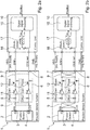
- Fig. 1a shows a block diagram of a first embodiment of a position sensor system 1, particularly for detecting rotary movement, in a first operating condition.
- the position sensor system 1 comprises a position sensor 2, particularly for detecting rotary movement, with a first sensor output 3 and a second sensor output 4.
- the position sensor system 1 further comprises a first signal processing unit 5 for processing, particularly amplifying and filtering, the signal of the first sensor output 3 or the second sensor output 4, and a second signal processing unit 6 for processing, particularly amplifying and filtering, the signal of the second sensor output 4 or the first sensor output 3.
- the signal of the first sensor output 3 and the second sensor output 4 are either processed by the first signal processing unit 5 or the second signal processing unit 6 at a time. Thus, if the first sensor output 3 is processed by the first signal processing unit 5 the second sensor output 4 is processed by the second signal processing unit 6 and if the first sensor output is processed by the second signal processing unit 6 the second sensor output 4 is processed by the first signal processing unit 5.
- the position sensor system 1 further comprises a first system output 7 providing the output of the first signal processing unit 5 or of the second signal processing unit 6 and a second system output 8 providing the output of the second signal processing unit 6 or of the first signal processing unit 5.
- a first system output 7 providing the output of the first signal processing unit 5 or of the second signal processing unit 6
- a second system output 8 providing the output of the second signal processing unit 6 or of the first signal processing unit 5.
- the position sensor system 1 further comprises a swapping unit 9 for swapping the first signal processing unit 5 from the first sensor output 3 and the first system output 7 to the second sensor output 4 and second system output 8 and for simultaneously swapping the second signal processing unit 6 from the second sensor output 4 and second system output 8 to the first sensor output 3 and first system output 7 and vice versa.
- the swapping unit 9 is identified by two dashed circles, one between the position sensor 2 and the signal processing units 5, 6 and the other between the signal processing units 5, 6 and the system outputs 7, 8, i.e. at the two locations where the swapping takes place.
- the first sensor output 3 is connected to the first signal processing unit 5 and the output of the first signal processing unit 5 is connected to the first system output 7. Consequently, the second sensor output 4 is connected to the second signal processing unit 6 and the output of the second signal processing unit 6 is connected to the second system output 8.
- the first signal processing unit 5 and the second signal processing unit 6 each comprise an amplifier 11 and a filter 12.
- the amplifier 12 is for example an operation amplifier (op-amp) and the filter 12 is for example a resistor-capacitor circuit (RC circuit).
- the first signal processing unit 5 and/or the second signal processing unit 6 can add some offset error, gain error and/or phase error, as indicated in Fig. 1a by the corresponding arrows.
- the position sensor system 1 of Fig. 1a further comprises a control unit 10.
- the control unit 10 can be either integral with the position sensor system 1, i.e. on the same chip, or external of the position sensor system 1 and connected to the position sensor system 1 by e.g. a cable.
- Fig. 1a refers to an external control unit 10, as indicated by the connection points and lines between the position sensor system 1 and the control unit 10.
- the control unit 10 in Fig. 1a comprises a first analog-to-digital converter 13 for the first system output 7 and a second analog-to-digital converter 14 for the second system output 8.
- the output of the first analog-to-digital converter 13 and of the second analog-to-digital converter 14 are processed by the same digital signal processing unit 15.
- the control unit 10, especially the digital signal processing unit 15, is designed to detect ripples 18 in the first system output7 and/or second system output 8, caused by swapping the first signal processing unit 5 and the second signal processing unit 6.
- control unit 10 especially the digital signal processing unit 15, is designed to determine the magnitude for the ripples 18 in the first system output 7 and second system output 8.
- control unit 10 can determine the 2 nd derivate of the first system output 7 and of the second system output 8 and detect peaks in the 2 nd derivates.
- the peaks represent errors in the first signal processing unit 5 respectively in the second signal processing unit 6, especially offset, gain and/or phase errors.
- control unit 10 can calculate the average of the first system output 7 respectively the second system output 8.
- Fig. 1b shows a block diagram of the position sensor system 1 of Fig. 1a in a second operating condition.
- the first sensor output 3 is connected to the second signal processing unit 6 and the second signal processing unit 6 is connected to the first system output 5.
- the second sensor output 4 is connected to the first signal processing unit 5 and the first signal processing unit 5 is connected to the second system output 8.
- the swapping unit 9 has swapped the first signal processing unit 5 from the first sensor output 3 and first system output 7 to the second sensor output 4 and second system output 8 and simultaneously swapped the second signal processing unit 6 from the second sensor output 4 and second system output 8 to the first sensor output 3 and first system output 7.
- the swapping unit 9 changes the operating condition of the position sensor system 1.
- the system outputs 7, 8 may contain ripples 18, which are detected by the control unit 10.
- Fig. 1b the swapping unit 9 is again identified by two dashed circles.
- the swapping of the signal processing units 5, 6 is identified by the crossings in the two dashed circles.
- the first sensor output 3 is processed by the first signal processing unit 5 and provided to the first system output 7 and the second sensor output 4 is processed by the second signal processing unit 6 and provided to the second system output 8.
- the first sensor output 3 is processed by the second signal processing unit 6 and provided to the first system output 7 and the second sensor output 4 is processed by the first signal processing unit 5 and provided to the second system output 8.
- the swapping unit 8 causes an alternation between the first operating condition and the second operating condition.
- the first signal processing unit 5 and the second processing unit 6 amplify and filter the first sensor output 3 and the second output 4 and thereby eventually adding offset errors, gain errors and/or phase errors.
- the first system output 7 and the second system output 8 are processed by the control unit 10.
- the first system output 7 is converted by the first analog-to-digital converter 13 of the control unit 10 and the second system output 8 is converted by the second analog-to-digital converter 14 of the control unit 10.
- the signals of the first analog-to-digital converter 10 and of the second analog-to-digital converter 14 are processed by the digital signal processing unit 15 of the control unit 10.
- the control unit 10 detects ripples 18 in the first system output 7 and/or the second system output 8, which are caused by alternating between the first operating condition and the second operating condition, i.e. by processing the sensor output signals 3, 4 by different signal processing nits 5, 6 in the two operating conditions.
- control unit 8 can determine the kind of error, i.e. offset error, gain error and/or phase error.
- the accuracy of the error detection can be enhanced by calculating the 2 nd derivate of the first system output 7 and of the second system output 8 and detecting peaks in the calculated 2 nd derivates.
- the peaks represent errors in the first signal processing unit 5 respectively in the second signal processing unit 6.
- the swapping unit 9 swaps the first signal processing unit 5 and second signal processing unit 6 regularly, preferably in equal intervals.
- Figs. 2a and 2b show a block diagram of a position sensor system 1 according to a second embodiment of the invention in a first operating condition respectively in a second operating condition.
- the second embodiment of the position sensor system 1 shown in Figs, 2a and 2b differs from the first embodiment of the position sensor system 1 shown in Figs. 1a and 1b in that the control unit 10 only comprises a common analog-to digital converter 17 instead of a first analog-to-digital converter 13 and a second analog-to-digital converter 18.
- the control unit 10 comprises a multiplexer 16 for multiplexing between the first system output 7 and the second system output 8.
- the multiplexer 16 is preferably by the control unit 10 and a corresponding information is used by the digital signalling processing unit 15, so that the digital signal processing unit 15 can assign the current received digital signals from the common analog-to-digital converter 17 to the first system output 7 respectively second system output 8.
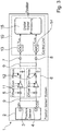
- Fig. 3 shows a third embodiment of a position sensor system 1 according to the invention in a first operating condition.
- the third embodiment of Fig. 3 differs from the first embodiment of Figs. 1a and 1b in that the control unit 10 is an internal control unit 10.
- the first system output 7 and the second system output 8 are internal to the position sensor system 1.
- the third embodiment is not shown in the second operating condition.
- the internal control unit 15 can also be used for the second embodiment shown in Figs. 2a and 2b accordingly.
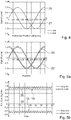
- Fig. 4 shows exemplary outputs of the first sensor output 3 and the second sensor output 4 in an error-free situation with no offset, ideal amplitude matching and ideal 90° phase shift between Sine-signal 20 and Cosine-signal 21, resulting in no swapping ripple.
- the horizontal axis of Fig. 4 represents the mechanical rotation, in this case 360° and the vertical axis represents the signal level of the first sensor output 3 and the second sensor output 4. In this case the maximum signal level is 1,0.
- the first sensor output 3 provides a sinusoidal signal, which starts with a signal level of 0 at 0°.
- the sinusoidal signal of the first sensor output 3 is referred to as Sine-signal 20.
- the second sensor output 4 also provides a sinusoidal signal, which is phase shifted by a quarter of a phase respectively 90°. Thus, the signal level of the second sensor output 4 is 1,0 at 0°.
- the sinusoidal signal of the second sensor output is referred to as Cosine-signal 21.
- the first sensor output is defined by: A * sin x ⁇ ⁇ 180 x in degree , or A * sin x x in radians
- the second sensor output is defined by: A * sin x + 90 ⁇ ⁇ 180 or A * cos x ⁇ ⁇ 180 x in degree , or A * sin x + ⁇ 2 or A * cos x x in radians .
- the peak amplitude respectively the signal level A is 1,0 in Fig. 4 .
- Fig. 5a shows an error case where the second signal processing unit 6 has an offset error of 10% relative to the maximum signal amplitude of 1,0.
- Fig. 5a shows the Sine-signal 22 and Cosine-signal 23 of the first system output 7 respectively the second system output 8 with the offset error over a full phase (0° to 360°).
- Fig. 5b shows the output of a static sensor located at 120° of Fig. 5a in the time domain.
- the horizontal time axis is a relative number, representing 40 swapping cycles (20 swapping periods).
- the deviation between the signals of the two operating conditions (swapped and un-swapped) is visible as a rectangular signal, toggling between two signal levels.
- This rectangular signal is referred to as ripples 18.
- the ripples of the swapped Sine-signal 22 are indicated by numeral 28 and the ripples of the swapped Cosine-signal 23 are indicated by numeral 29.
- Fig. 5b shows the averages for the ripples 28 of the swapped Sine-signal 22 and the ripples 29 of the swapped Cosine-signal 23.
- Fig. 5c shows the offset error for the Sine-signal 22 and Cosine-signal 23 of Fig. 5a and the magnitude both signals Sin ⁇ signal 22 2 + Cosine ⁇ signal 23 2 over a full phase (0° to 360°).
- An indication of an offset error is that at any position the error of the Sine-signal 22 and Cosine-signal 23 is constant and equal.
- Fig. 5d shows the total errors calculated from the un-swapped signal 31 and swapped signal 30 at the first system output 7 and the second system output 8 and the averaged total error.
- Fig. 6a shows an error case where the second signal processing unit has a gain error of 10% relative to the maximum signal amplitude of 1,0.
- Fig. 6a shows the Sine-signal 24 and Cosine-signal 25 of the first system output 7 respectively the second system output 8 with the gain error over a full phase (0° to 360°).
- Fig. 6b shows the output of a static sensor located at 120° of Fig. 6a in the time domain.
- the horizontal time axis is a relative number, representing 40 swapping cycles (20 swapping periods).
- the deviation between the signals of the two operating conditions (swapped and un-swapped) is visible as a rectangular signal, toggling between two signal levels.
- This rectangular signal is referred to as ripple 18.
- the ripples of the swapped Sine-signal 24 are indicated by numeral 28 and the ripples of the swapped Cosine-signal 25 are indicated by numeral 29.
- Fig. 6b shows the averages for the ripples 28 of the swapped Sine-signal 24 and the ripples 29 of the swapped Cosine-signal 25.
- Fig. 6c shows the gain error for the Sine-signal 24 and Cosine-signal 25 of Fig. 6a and the magnitude both signals Sin ⁇ signal 24 2 + Cosine ⁇ signal 25 2 over a full phase (0° to 360°).
- the largest error of the Sine-signal 24 respectively the Cosine-signal 25 occurs at the positive and negative peaks (90°,270° for Sine-signal 24, 0°,180° for Cosine-signal 25) and the minimum errors occurs at the zero crossings (0°,180° for Sine-signal 24, 90°,270° for Cosine-signal 25).
- An indication of a gain error is that the errors of the Sine-signal 24 and Cosine-signal 25 are not constant over a full phase, but the magnitude of both signals is constant.
- Fig. 6d shows the total errors calculated from the un-swapped signal 31 and swapped signal 30 at the first system output 7 and the second system output 8 and the averaged total error.
- Fig. 7a shows an error case where the second signal processing unit has a phase shift error of 6° compared to the first signal processing unit 7.
- Fig. 7a shows the Sine-signal 26 and Cosine-signal 27 of the first system output 7 respectively the second system output 8 having a phase shift error over a full phase (0° to 360°).
- Fig. 7b shows the output of a static sensor located at 120° of Fig. 7a in the time domain.
- the horizontal time axis is a relative number, representing 40 swapping cycles (20 swapping periods).
- the deviation between the signals of the two operating conditions (swapped and un-swapped) is visible as a rectangular signal, toggling between two signal levels. This rectangular signal is referred to as ripples 18.
- the ripples of the swapped Sine-signal 26 are indicated by numeral 28 and the ripples of the swapped Cosine-signal 27 are indicated by numeral 29.
- Fig. 7b shows the averages for the ripples 28 of the swapped Sine-signal 26 and the ripples 29 of the swapped Cosine-signal 27.
- Fig. 7c shows the phase shift error for the Sine-signal 26 and Cosine-signal 27 of Fig. 7a and the magnitude both signals Sin ⁇ signal 26 2 + Cosine ⁇ signal 27 2 over a full phase (0° to 360°).
- the largest error of the Sine-signal 26 respectively the cosine-signal 27 occurs at zero crossings (0°,180° for Sine-signal 26, 90°,270° for Cosine-signal 27) and the minimum errors occurs at the positive and negative peaks (90°,270° for Sine-signal 26, 0°,180° for Cosine-signal 27).
- An indication of a phase shift error is that the errors of the Sine-signal 26 and Cosine-signal 27 are not constant over a full phase, but the magnitude of both signals is constant.
- Fig. 7d shows the total errors calculated from the un-swapped signal 31 and swapped signal 30 at the first system output 7 and the second system output 8 and the averaged total error.
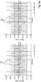
- Fig. 8a shows the 2 nd derivate of the Sine-signal 22 and Cosine-signal 23 of Fig. 5a referring to the offset error.
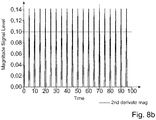
- Fig. 8b shows the magnitude of the 2 nd derivates of Fig. 8a f " Sine ⁇ Signal 22 2 + f " Cosine ⁇ Signal 23 2 .
- Fig. 8a is split into two graphs due to the overlapping of the 2 nd derivate of the Sine-Signal 22 and the 2 nd derivate of the Cosine-Signal 23.
- the vertical axis on both graphs is a relative number representing the 2 nd derivate of the signals. It depends on the time interval between measurements of the signal ripple 18 on the Sine-Signal 22 and Cosine-signal 24, representing the sample rate of the analog-to-digital converter 13, 14, 17 analysing the Sine-signal 22 and Cosine-signal 23. The larger the error, the larger will be these signal levels.
- the horizontal axis of Fig. 8a represents the position of the position sensor 2 in electrical degrees and the horizontal axis of Fig. 8b is a relative number representing 20 swapping cycles (10 swapping periods).
- An offset error in the first signal processing unit 5 and/or second signal processing unit 6 is indicated by a constant 2 nd derivate pulse over position.
- the 2 nd derivate magnitude is also constant over position.
- Fig. 9a shows the 2 nd derivate of the Sine-signal 24 and Cosine-signal 25 of Fig. 6a referring to the gain error.
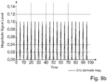
- Fig. 9b shows the magnitude of the 2 nd derivates of Fig. 9a f " Sine ⁇ Signal 24 2 + f " Cosine ⁇ Signal 25 2 .
- Fig. 9a is split into two graphs due to the partial overlapping of the 2 nd derivate of the Sine-Signal 24 and the 2 nd derivate of the Cosine-Signal 25.
- Fig. 9a and 9b otherwise correspond to Fig. 8a and 8b , especially with respect to the axis.
- a gain error in the first signal processing unit 5 and/or second signal processing unit 6 is indicated by a non-constant 2 nd derivate peak pulse pattern over position.
- the 2 nd derivate magnitude is constant over position and time.
- Fig. 10a shows the 2 nd derivate of the Sine-signal 26 and Cosine-signal 27 of Fig. 7a referring to the phase shift error.
- Fig. 10b shows the magnitude of the 2 nd derivates of Fig. 10a f " Sine ⁇ Signal 26 2 + f " Cosine ⁇ Signal 27 2 .
- Fig. 10a is split into two graphs due to the partial overlapping of the 2 nd derivate of the Sine-Signal 22 and the 2 nd derivate of the Cosine-Signal 23.
- Fig. 10a and 10b otherwise correspond to Fig. 8a and 8b , especially with respect to the axis.
- a phase shift error in the first signal processing unit 5 and/or second signal processing unit 6 is indicated by a non-constant 2 nd derivate peak pulse pattern over position.
- the 2 nd derivate magnitude is constant over position and time.
- Fig. 11 shows a block diagram of a position sensor system 1 according to the prior art.
- the position sensor system 1 comprises a position sensor 2 with a first sensor output 3 and a second sensor output 4.
- the position sensor system 1 further comprises a signal processing unit 32 for processing, particularly amplifying and filtering, the signal of the first sensor output 3 and the second sensor output 4.
- the signal processing unit 32 comprises a multiplexer 34 to multiplex between the first sensor output 3 and the second sensor output 4.
- the signal processing unit 32 further comprises an amplifier 11 and a filter 12.
- the position sensor system 1 comprises a system output 33 providing the output of the signal processing unit 32.
- the position sensor system 1 of Fig. 11 further comprises a control unit 10.
- the control unit 10 can be either integral with the position sensor system 1, i.e. on the same chip, or external of the position sensor system 1 and connected to the position sensor system 1 by e.g. a cable.
- Fig. 11 refers to an external control unit 10, as indicated by the connection points and lines between the position sensor system 1 and the control unit 10.
- the control unit 10 in Fig. 11 comprises an analog-to-digital converter 17 for the system output 33.
- the output of the analog-to-digital converter 17 is processed by digital signal processing unit 15.
- the control unit 10, especially the digital signal processing unit 15 must have knowledge which sensor output 3, 4 is currently processed by the signal processing unit 32. Therefore, the control unit 10, especially the digital signal processing unit 15 controls the multiplexer 34 of the signal processing unit 32 via a control line 35. This requires additional wiring between the position sensor system 1 and the external control unit 10.
- a further disadvantage of this variant is that in a rotating position sensor system 1, due to the sequential processing of both signals, both position sensor signals are not measured at the same position as the item to be measured will have moved by a certain amount between the measurements of the two position sensor signals, which is particularly disadvantageous for high speed systems, as this error increases with rotating speed.
Landscapes
- Engineering & Computer Science (AREA)
- Physics & Mathematics (AREA)
- General Physics & Mathematics (AREA)
- Theoretical Computer Science (AREA)
- Quality & Reliability (AREA)
- General Engineering & Computer Science (AREA)
- Signal Processing (AREA)
- Transmission And Conversion Of Sensor Element Output (AREA)
Description
- The invention relates to a position sensor system, particularly for detecting rotary movement. The invention further relates to a method for detecting errors in a position sensor system, particularly for detecting rotary movement.
- A position sensor system, particularly for detecting rotary movements, includes a position sensor, particularly for detecting rotary movements of the item being measured. The item to be measured is for example a rotor in an electric motor.
- The position sensor provides the raw sensor data in the form of a sinusoidal signal, where one period of the sensor signal represents a full turn or fractions of a full turn of the item being measured.
- In order to improve the signal quality and to allow unambiguous position calculation over a full phase, a second sensor signal is introduced, which is again sinusoidal, but phase shifted by a quarter of a phase or 90 electrical degrees. Typically, the first sensor signal is designated as Sine-signal and the second sensor signal is designated as Cosine-signal.
- The first sensor signal is provided by a first sensor output and the second sensor signal is provided by a second sensor output.
- The position sensor system further comprises at least one signal processing unit, for processing the Sine-signal and Cosine-signal of the position sensor. Typically, the sensor signals are amplified and filtered by the signal processing unit. In practice, such a signal path of the position sensor system may contain errors, which can be categorized into offset errors, gain mismatch errors and phase errors.
- Offset errors refer to a shifting of one or both of the sensor signals in the voltage domain to either positive or negative direction. Gain mismatch errors refer to different gains of the Sine-signal path and the Cosine-signal path and phase errors refer to a phase shift between the two sensor signals that is lower or higher than the nominal 90°.
- The output of the at least one signal processing unit, which corresponds to the output of the position sensor system, is afterwards processed by an electronic control unit, which for example comprises an analog-to-digital converter and a digital signal processing unit. The electronic control unit can be internal or external of the position sensor system.
- According to a variant of the prior art the signal processing unit comprises a multiplexer at the input of the signal processing unit. A block diagram of such a position sensor system is shown in
Fig. 11 . The Sine-signal and the Cosine-signal of the position sensor are sequentially processed, i.e. amplified and filtered, by the signal processing unit and passed to the electronic control unit. - The electronic control unit must provide a control signal to the multiplexer of the signal processing unit in order to distinguish which signal is being selected by the multiplexer. The advantage of this variant is, that both position sensor signals, i.e. Sine-signal and Cosine-signal, are processed (amplified and filtered) by the same signal processing unit. Thus, there is no gain mismatch as both are processed by the same signal processing unit, i.e. the same amplifier. Likewise, any parasitic phase shift aside from the intrinsic 90° phase shift between Sine-signal and Cosine-signal introduced by the signal processing unit will be the same for both position sensor signals. Offset errors are not cancelled by this variant, however both signals will have the same additional offset (if any) introduced by the signal processing unit. Another advantage of this variant is that the signal processing unit is only required once for both signals. A disadvantage of this variant is that in a rotating position sensor system, due to the sequential processing of both signals, both position sensor signals are not measured at the same position as the item to be measured will have moved by a certain amount between the measurements of the two position sensor signals, which is particularly disadvantageous for high speed systems, as this error increases with rotating speed. A further disadvantage of this variant is the required feedback from the electronic control unit to the multiplexer of the signal processing unit, requiring additional signal wires, which is the reason that this variant is typically used for position sensor systems where the electronic control unit is on the same chip as the position sensor system.
- Pursuant to another variant of the prior art the Sine-signal and Cosine-signal of the position sensor are processed in parallel by two signal processing units, i.e. each position sensor signal is amplified and filtered by a separate signal processing unit. This provides the fastest possible signal processing, but it requires two signal processing units, i.e. two amplifiers and two filters. There will always be some residual gain, offset and/or phase mismatch between these amplifiers. Since the position sensor signals are processed in parallel the position sensor system has two outputs, each corresponding to the output of one signal processing unit.
- The electronic control unit can process the two position sensor outputs in parallel by two analog-to-digital converters, which forward the digital signals to a common digital signal processing unit. However, there will be non-linearity differences in the two analog-to-digital converters.
- Alternatively, the two position sensor system outputs can be processed by a control unit having a multiplexed analog-to-digital converter. The multiplexer is part of the control unit, which has full control of the multiplexer and is typically on the same chip. The limiting factor of this variant is the processing speed of the control unit, especially of the analog-to-digital converter. This variant poses the same issues with offset, gain and phase mismatch of the two signal processing units of the position sensor system, but eliminates non-linearity differences due to using only one analog-to-digital converter.
- The document
US 2018/231396 A1 describes a system comprising a position sensor with two differential sensor outputs the polarity of which can be selectively inverted before being processed in parallel by two differential amplifiers with differential outputs that are subtracted from one another. The subtracted signals are then selectively inverted or not such as to restore the initial polarity. - It is an object of the present invention to detect any gain, offset and phase mismatch of a position sensor system comprising two signal processing units for processing the Sine-signal and Cosine-signal of a position sensor in parallel, especially for high speed position sensor systems.
- This object is solved according to the invention by a position sensor system, particularly for detecting rotary movement, comprising:
- a position sensor, particularly for detecting rotary movement, with a first sensor output and a second sensor output,
- a first signal processing unit for processing, particularly amplifying and filtering, the signal of the first sensor output or the second sensor output,
- a second signal processing unit for processing, particularly amplifying and filtering, the signal of the second sensor output or the first sensor output,
- a first system output providing the output of the first signal processing unit or of the second signal processing unit, and
- a second system output providing the output of the second signal processing unit or of the first signal processing unit,
- which is characterized in that
- the position sensor system further comprises a swapping unit for swapping the first signal processing unit from the first sensor output and first system output to the second sensor output and second system output and for simultaneously swapping the second signal processing unit from the second sensor output and second system output to the first sensor output and first system output and vice versa.
- The position sensor system according to the invention has a first operating condition, in which the first sensor output is connected to the first signal processing unit and the output of the first signal processing unit is connected to the first system output and in which the second sensor output is connected to the second signal processing unit and the output of the second signal processing unit is connected to the second system output. The swapping unit for swapping the first signal processing unit from the first sensor output and first system output to the second sensor output and second system output and for simultaneously swapping the second signal processing unit from the second sensor output and second system output to the first sensor output and first system output transfers the position sensor system to a second operating condition. In the second operating condition the first sensor output is connected to the second signal processing unit and the output of the second signal processing unit is connected to the first system output and in the second sensor output is connected to the first signal processing unit and the output of the first signal processing unit is connected to the second system output. Thus, the swapping unit transfers the position sensor system from a first operating condition to a second operating condition and back to the first operating condition and so on.
- By swapping the first signal processing unit and the second signal processing unit between the first sensor out and first system output and the second sensor output and second system output the position sensor signals are processed alternatingly by the first signal processing unit and the second signal processing unit. By detecting any differences between the processing by the first signal processing unit and the processing by the second signal processing unit, it is possible to detect any gain, offset and phase mismatch of the position sensor system. Any mismatch between the first signal processing unit and second processing unit is measurable as a ripple on the outputs of the first signal processing unit and second processing unit. Furthermore, the position sensor system allows fast error detection at slow rotating speeds or at static positions of the position sensor.
- Additionally, by averaging the swapped and un-swapped signals, i.e. the signals for a specific position sensor output processed by the first signal processing unit and the signals processed by the second processing unit, a gain mismatch can be compensated.
- Preferably, the swapping unit swaps the first signal processing unit and second processing unit, i.e. between the first operating condition and the second operating condition, regularly, preferably in equal intervals.
- In a preferred variant of the invention the first sensor output provides a sinusoidal signal and the second sensor output provides a sinusoidal signal, which is phase shifted by a quarter of one phase or 90 electrical degrees. Such a first sensor signal and second sensor signal are referred to as Sine-signal respectively Cosine-signal. However, the invention is not limited to sinusoidal sensor signals and/or phase shifts of a quarter of one phase or 90 electrical degrees.
- Pursuant to variant of the invention the first signal processing unit and the second signal processing unit each comprise an amplifier and a filter, for amplifying and filtering the first sensor output and second sensor output.
- According to a particularly preferred variant of the invention the position sensor system further comprises a control unit for processing the first system output and the second system output. The control unit can be internal or external and especially on the same chip or a different chip as the position sensor system.
- In accordance with a variant of the invention the control unit comprises a first analog-to-digital converter for the first system output, a second analog-to-digital converter for the second system output, and a digital signal processing unit for processing the signals of the first analog-to-digital converter and the second analog-to-digital converter. Thus, the signals of the first system output and the second system output are processed in parallel by the first analog-to-digital converter respectively the second analog-to-digital converter of the control unit. This provides the fastest possible signal processing but might add some non-linearity differences due to the two analog-to-digital converters.
- In an alternative variant of the invention the control unit comprises a multiplexer for multiplexing between the first system output and the second system output and a common analog-to-digital converter connected to the output of the multiplexer, and a digital signal processing unit for processing the signal of the common analog-to-digital converter. This variant is limited by the processing speed of the analog-to-digital converter. Since the multiplexer and the control unit controlling the multiplexer are typically on the same chip, this is not excessively limiting the processing speed. Since only one analog-to-digital converter is used in this variant, the possible non-linearity differences due to the two analog-to-digital converters are avoided.
- In either alternative the digital signal processing unit usually does not limit the processing speed due to the current processing speeds and available multi-core processors.
- The control unit is particularly designed to detect ripples in the first system output and/or second system output caused by swapping the first signal processing unit and the second signal processing unit, i.e. caused by alternating between the first operating condition and the second operating condition. If there is any gain, offset and/or phase mismatch the first system output and the second system output will change simultaneously with the swapping of the signal processing units. This change in the first system output and second system output is referred to as ripple, which is detected by the control unit. If the swapping occurs in regular intervals, the ripple will also change in these intervals.
- According to the invention the position sensor is mounted on a non-moving part of the item to be measured.
- Pursuant to a variant of the invention, the control unit further determines the magnitude of the ripples in the first system output and or second system output. This helps to measure and distinguish any offset errors, gain mismatch errors and phase errors.
- According to a preferred variant of the invention the control unit determines the 2nd derivate of the first system output and of the second system output and detects peaks in the calculated 2nd derivates representing errors in the first signal processing unit respectively in the second signal processing unit. Ripple determination is negatively influenced by signal noise in the first signal processing unit, in the second signal processing unit and/or in case the item to be measured is rotating during ripple determination. Improved results can be achieved by determining the 2nd derivate of the first system output and the second system output, representing their respective acceleration. Since the rate of change in a swapping step, i.e. switching between the first operating condition and the second operating condition, is significantly faster than a typical rotational movement of the item to be measured these cases can be easily distinguished. Likewise, the swapping step can be easily distinguished from the noise typically occurring in analog signal processing.
- In a variant of the invention the control unit calculates the average of the first system output respectively of the second system output. By determining the average of the system output signals, any gain mismatch errors between the two signal processing units can be compensated. Further, by determining the average any phase errors can be reduced to a constant level over a full signal period and any offset errors can be reduced.
- Preferably, the position sensor is a magnetic sensor, an inductive sensor or an eddy current sensor, particularly a Hall sensor, an anisotropic magneto resistance sensor, a tunnelling magneto resistance sensor or a giant magneto resistance sensor.
- The position sensor system can comprise more than one position sensor. Preferably the position sensor system comprises two separate signal processing units and a corresponding swapping unit for each position sensor. By providing more than one, further preferred at least three, position sensors, that data of the position sensors can be compared to each other, to detect errors in the data of the position sensors. By having more than two position sensors it is easier to detect the position sensor which provides signals with errors.
- The object is further solved according to the invention by a method for detecting errors in a position sensor system, particularly for detecting rotary movement, comprising:
- a first operating condition, in which a first sensor output is processed by a first signal processing unit and provided to a first system output and in which a second sensor output is processed by a second signal processing unit and provided to a second system output, and
- a second operating condition, in which the first sensor output is processed by the second signal processing unit and provided to the first system output and in which the second sensor output is processed by the first signal processing unit and provided to the second system output,
- and further comprising the step of alternating between the first operating condition and the second operating condition.
- In the first operating condition of the position sensor the first sensor signal is processed by the first signal processing unit and provided to the first system output and the second system sensor output is processed by the second signal processing unit and provided to the second system output. By swapping the signal processing units, the position sensor system is in the second operating state, in which the first sensor output is processed by the second signal processing unit and provided to the first system output and in which the second sensor output is processed by the first signal processing unit and provided to the second system output. According to inventive method the first and second operating states alternate.
- By detecting any differences between the processing by the first signal processing unit and the processing by the second signal processing unit, it is possible to detect any gain, offset and phase mismatch. Any mismatch between the first signal processing unit and second processing unit is measurable as a ripple on the outputs of the first signal processing unit and second processing unit. Furthermore, the position sensor system allows fast error detection at slow rotating speeds or at static positions of the position sensor.
- In a preferred variant of the invention the first sensor output provides a sinusoidal signal and the second sensor output provides a sinusoidal signal, which is phase shifted by a quarter of one phase or 90 electrical degrees. Such a first sensor signal and second sensor signal are referred to as Sine-signal respectively Cosine-signal. However, the invention is not limited to sinusoidal sensor signals and/or phase shifts of a quarter of one phase or 90 electrical degrees.
- Pursuant to variant of the invention the first signal processing unit and the second signal processing unit each amplify and filter the first sensor output or second sensor out, depending on the current operating state. Therefore, the first signal processing unit and the second signal processing unit each comprise an amplifier and a filter.
- According to a particularly preferred variant of the invention the first system output and the second system output are processed by a control unit. The control unit can be internal or external and especially on the same chip or a different chip as the position sensor system.
- In a variant of the invention the first system output is converted by a first analog-to-digital converter and the second system output is converted by a second analog-to-digital converter of the control unit. Thus, the signals of the first system output and the second system output are processed in parallel by the first analog-to-digital converter respectively the second analog-to-digital converter of the control unit. This provides the fastest possible signal processing but might add some non-linearity differences due to the two analog-to-digital converters.
- Alternatively, the control unit multiplexes between the first system output and the second system output and converts the multiplexed signal by a common analog-to-digital converter. This variant is limited by the processing speed of the analog-to-digital converter. Since the multiplexer and the control unit controlling the multiplexer are typically on the same chip, this is not excessively limiting the processing speed. Since only one analog-to-digital converter is used in this variant, the possible non-linearity differences due to the two analog-to-digital converters are avoided.
- Advantageously, the signals of the first analog-to-digital converter and of the second analog-to-digital converter or of the common analog-to-digital converter are processed by a digital signal processing unit. The digital signal processing unit usually does not limit the processing speed due to the current processing speeds and available multi-core processors.
- Pursuant to a variant of the invention the method comprises the step of determining the ripples in the first system output and/or second system output overtime for a static position sensor and/or over the position of the sensor.
- In a preferred variant of the invention the method comprises the step of determining the magnitude for the ripples in the first system output and second system output. This helps to measure and distinguish any offset errors, gain mismatch errors and phase errors.
- According to a particularly preferred variant of the invention the method comprises the step of calculating the 2nd derivate of the first system output and of the second system output and detecting peaks in the calculated 2nd derivates representing errors in the first signal processing unit respectively in the second signal processing unit. Improved results can be achieved by determining the 2nd derivate of the first system output and the second system output, representing their respective acceleration. Since the rate of change in a swapping step, i.e. switching between the first operating condition and the second operating condition, is significantly faster than a typical rotational movement of the item to be measured these cases can be easily distinguished. Likewise, the swapping step can be easily distinguished from the noise typically occurring in analog signal processing.
- In accordance with a variant of the invention the method comprises the step of determining the average of the first system output and of the second system output. By determining the average of the system output signals, any gain mismatch errors between the two signal processing units can be compensated. Further, by determining the average any phase errors can be reduced to a constant level over a full signal period and any offset errors can be reduced.
- Preferably, step of alternating between the first operating condition and the second operating condition is executed regularly, preferably in equal intervals.
- In the following the invention will be further explained with respect to the embodiments shown in the figures. It shows:
- Fig. 1a
- a block diagram of a position sensor system according to a first embodiment of the invention in a first operating condition,
- Fig. 1b
- a block diagram of the position sensor system of
Fig. 1a in a second operating condition, - Fig. 2a
- a block diagram of a position sensor system according to a second embodiment of the invention in a first operating condition,
- Fig. 2b
- a block diagram of the position sensor system of
Fig. 2a in a second operating condition, - Fig. 3
- a block diagram of a position sensor system according to a third embodiment of the invention in a first operating condition,
- Fig. 4
- a diagram showing output signals of a swapped position sensor system without error in the signal path,
- Fig. 5a
- a diagram showing output signals of a swapped position sensor system with an offset error,
- Fig. 5b
- a diagram showing an output of a static position sensor with the offset error of
Fig. 5a over time, - Fig. 5c
- a diagram showing the offset error of the signals of
Fig. 5a over position and the magnitude of the offset error over position, - Fig. 5d
- a diagram showing the total error of the signals of
Fig. 5a over position and the total average error, - Fig. 6a
- a diagram showing output signals of a swapped position sensor system with an amplitude error,
- Fig. 6b
- a diagram showing an output of a static position sensor with the amplitude error of
Fig. 6a over time, - Fig. 6c
- a diagram showing the amplitude error of the signals of
Fig. 6a over position and the magnitude of the amplitude error over position, - Fig. 6d
- a diagram showing the total error of the signals of
Fig. 6a over position and the total average error over position, - Fig. 7a
- a diagram showing output signals of a swapped position sensor system with a phase error,
- Fig. 7b
- a diagram showing an output of a static position sensor with the phase error of
Fig. 7a over time, - Fig. 7c
- a diagram showing the phase error of the signals of
Fig. 7a over position and the magnitude of the phase error over position, - Fig. 7d
- a diagram showing the total error of the signals of
Fig. 7a over position and the total average error over position, - Fig. 8a
- a diagram showing the second derivate for output signals of a position sensor system with an offset error over position,
- Fig. 8b
- a diagram showing the magnitude of the signals of
Fig. 8a over time, - Fig. 9a
- a diagram showing the second derivate for output signals of a position sensor system with an amplitude error over position ,
- Fig. 9b
- a diagram showing the magnitude of the signals of
Fig. 9a over time, - Fig. 10a
- a diagram showing the second derivate for output signals of a position sensor system with a phase error over position,
- Fig. 10b
- a diagram showing the magnitude of the signals of
Fig. 10a over time, and - Fig. 11
- a block diagram of a position sensor system according to the prior art.
-
Fig. 1a shows a block diagram of a first embodiment of aposition sensor system 1, particularly for detecting rotary movement, in a first operating condition. Theposition sensor system 1 comprises aposition sensor 2, particularly for detecting rotary movement, with afirst sensor output 3 and asecond sensor output 4. Theposition sensor system 1 further comprises a firstsignal processing unit 5 for processing, particularly amplifying and filtering, the signal of thefirst sensor output 3 or thesecond sensor output 4, and a secondsignal processing unit 6 for processing, particularly amplifying and filtering, the signal of thesecond sensor output 4 or thefirst sensor output 3. - The signal of the
first sensor output 3 and thesecond sensor output 4 are either processed by the firstsignal processing unit 5 or the secondsignal processing unit 6 at a time. Thus, if thefirst sensor output 3 is processed by the firstsignal processing unit 5 thesecond sensor output 4 is processed by the secondsignal processing unit 6 and if the first sensor output is processed by the secondsignal processing unit 6 thesecond sensor output 4 is processed by the firstsignal processing unit 5. - The
position sensor system 1 further comprises afirst system output 7 providing the output of the firstsignal processing unit 5 or of the secondsignal processing unit 6 and asecond system output 8 providing the output of the secondsignal processing unit 6 or of the firstsignal processing unit 5. Again, at a given time the output of the firstsignal processing unit 5 is provided by either thefirst system output 7 or thesecond system output 8 and the output of the secondsignal processing unit 6 is provided at that time by the other of thesecond system output 8 or thefirst system output 7. Thus, if the output of the firstsignal processing unit 5 is provided by thefirst system output 7 the output of the secondsignal processing unit 6 is provided by thesecond system output 8 and if the output of the firstsignal processing unit 5 is provided by thesecond system output 8 the output of the secondsignal processing unit 6 is provided by thefirst system output 7. - According to the invention the
position sensor system 1 further comprises aswapping unit 9 for swapping the firstsignal processing unit 5 from thefirst sensor output 3 and thefirst system output 7 to thesecond sensor output 4 andsecond system output 8 and for simultaneously swapping the secondsignal processing unit 6 from thesecond sensor output 4 andsecond system output 8 to thefirst sensor output 3 andfirst system output 7 and vice versa. InFig. 1a theswapping unit 9 is identified by two dashed circles, one between theposition sensor 2 and thesignal processing units signal processing units - In the first operating condition of
Fig. 1a thefirst sensor output 3 is connected to the firstsignal processing unit 5 and the output of the firstsignal processing unit 5 is connected to thefirst system output 7. Consequently, thesecond sensor output 4 is connected to the secondsignal processing unit 6 and the output of the secondsignal processing unit 6 is connected to thesecond system output 8. - The first
signal processing unit 5 and the secondsignal processing unit 6 each comprise anamplifier 11 and afilter 12. Theamplifier 12 is for example an operation amplifier (op-amp) and thefilter 12 is for example a resistor-capacitor circuit (RC circuit). The firstsignal processing unit 5 and/or the secondsignal processing unit 6 can add some offset error, gain error and/or phase error, as indicated inFig. 1a by the corresponding arrows. - The
position sensor system 1 ofFig. 1a further comprises acontrol unit 10. Thecontrol unit 10 can be either integral with theposition sensor system 1, i.e. on the same chip, or external of theposition sensor system 1 and connected to theposition sensor system 1 by e.g. a cable.Fig. 1a refers to anexternal control unit 10, as indicated by the connection points and lines between theposition sensor system 1 and thecontrol unit 10. - The
control unit 10 inFig. 1a comprises a first analog-to-digital converter 13 for thefirst system output 7 and a second analog-to-digital converter 14 for thesecond system output 8. The output of the first analog-to-digital converter 13 and of the second analog-to-digital converter 14 are processed by the same digitalsignal processing unit 15. - The
control unit 10, especially the digitalsignal processing unit 15, is designed to detectripples 18 in the first system output7 and/orsecond system output 8, caused by swapping the firstsignal processing unit 5 and the secondsignal processing unit 6. - Furthermore, the
control unit 10, especially the digitalsignal processing unit 15, is designed to determine the magnitude for theripples 18 in thefirst system output 7 andsecond system output 8. - To further increase the accuracy of the
position sensor system 1 thecontrol unit 10, especially the digitalsignal processing unit 15, can determine the 2nd derivate of thefirst system output 7 and of thesecond system output 8 and detect peaks in the 2nd derivates. The peaks represent errors in the firstsignal processing unit 5 respectively in the secondsignal processing unit 6, especially offset, gain and/or phase errors. - To reduce or compensate errors in the first
signal processing unit 5 and/or secondsignal processing unit 6 thecontrol unit 10, especially the digitalsignal processing unit 15, can calculate the average of thefirst system output 7 respectively thesecond system output 8. -
Fig. 1b shows a block diagram of theposition sensor system 1 ofFig. 1a in a second operating condition. In this second operating condition thefirst sensor output 3 is connected to the secondsignal processing unit 6 and the secondsignal processing unit 6 is connected to thefirst system output 5. Further, thesecond sensor output 4 is connected to the firstsignal processing unit 5 and the firstsignal processing unit 5 is connected to thesecond system output 8. Thus, theswapping unit 9 has swapped the firstsignal processing unit 5 from thefirst sensor output 3 andfirst system output 7 to thesecond sensor output 4 andsecond system output 8 and simultaneously swapped the secondsignal processing unit 6 from thesecond sensor output 4 andsecond system output 8 to thefirst sensor output 3 andfirst system output 7. By swapping thesignal processing units swapping unit 9 changes the operating condition of theposition sensor system 1. - Since the
sensor output signal processing units signal processing units ripples 18, which are detected by thecontrol unit 10. - In
Fig. 1b theswapping unit 9 is again identified by two dashed circles. The swapping of thesignal processing units - In the first operating condition shown in
Fig. 1a thefirst sensor output 3 is processed by the firstsignal processing unit 5 and provided to thefirst system output 7 and thesecond sensor output 4 is processed by the secondsignal processing unit 6 and provided to thesecond system output 8. - In the second operating condition shown in
Fig. 1b thefirst sensor output 3 is processed by the secondsignal processing unit 6 and provided to thefirst system output 7 and thesecond sensor output 4 is processed by the firstsignal processing unit 5 and provided to thesecond system output 8. - The
swapping unit 8 causes an alternation between the first operating condition and the second operating condition. - The first
signal processing unit 5 and thesecond processing unit 6 amplify and filter thefirst sensor output 3 and thesecond output 4 and thereby eventually adding offset errors, gain errors and/or phase errors. - The
first system output 7 and thesecond system output 8 are processed by thecontrol unit 10. Thefirst system output 7 is converted by the first analog-to-digital converter 13 of thecontrol unit 10 and thesecond system output 8 is converted by the second analog-to-digital converter 14 of thecontrol unit 10. The signals of the first analog-to-digital converter 10 and of the second analog-to-digital converter 14 are processed by the digitalsignal processing unit 15 of thecontrol unit 10. - The
control unit 10 detectsripples 18 in thefirst system output 7 and/or thesecond system output 8, which are caused by alternating between the first operating condition and the second operating condition, i.e. by processing thesensor output signals signal processing nits - By determining the magnitude for the
ripples 18 in thefirst system output 7 and thesecond system output 8 thecontrol unit 8 can determine the kind of error, i.e. offset error, gain error and/or phase error. - The accuracy of the error detection can be enhanced by calculating the 2nd derivate of the
first system output 7 and of thesecond system output 8 and detecting peaks in the calculated 2nd derivates. The peaks represent errors in the firstsignal processing unit 5 respectively in the secondsignal processing unit 6. - By determining the average of the
first system output 7 and of thesecond system output 8 the errors can be reduced or even compensated. - Advantageously, the
swapping unit 9 swaps the firstsignal processing unit 5 and secondsignal processing unit 6 regularly, preferably in equal intervals. -
Figs. 2a and 2b show a block diagram of aposition sensor system 1 according to a second embodiment of the invention in a first operating condition respectively in a second operating condition. The second embodiment of theposition sensor system 1 shown inFigs, 2a and 2b differs from the first embodiment of theposition sensor system 1 shown inFigs. 1a and 1b in that thecontrol unit 10 only comprises a common analog-todigital converter 17 instead of a first analog-to-digital converter 13 and a second analog-to-digital converter 18. In order to process thefirst system output 7 and thesecond system output 8, thecontrol unit 10 comprises amultiplexer 16 for multiplexing between thefirst system output 7 and thesecond system output 8. Themultiplexer 16 is preferably by thecontrol unit 10 and a corresponding information is used by the digitalsignalling processing unit 15, so that the digitalsignal processing unit 15 can assign the current received digital signals from the common analog-to-digital converter 17 to thefirst system output 7 respectivelysecond system output 8. -
Fig. 3 shows a third embodiment of aposition sensor system 1 according to the invention in a first operating condition. The third embodiment ofFig. 3 differs from the first embodiment ofFigs. 1a and 1b in that thecontrol unit 10 is aninternal control unit 10. Thus, thefirst system output 7 and thesecond system output 8 are internal to theposition sensor system 1. - Since all other features correspond to the first embodiment of
Figs. 1a and 1b the third embodiment is not shown in the second operating condition. Furthermore, theinternal control unit 15 can also be used for the second embodiment shown inFigs. 2a and 2b accordingly. -
Fig. 4 shows exemplary outputs of thefirst sensor output 3 and thesecond sensor output 4 in an error-free situation with no offset, ideal amplitude matching and ideal 90° phase shift between Sine-signal 20 and Cosine-signal 21, resulting in no swapping ripple. The horizontal axis ofFig. 4 represents the mechanical rotation, in thiscase 360° and the vertical axis represents the signal level of thefirst sensor output 3 and thesecond sensor output 4. In this case the maximum signal level is 1,0. - The
first sensor output 3 provides a sinusoidal signal, which starts with a signal level of 0 at 0°. The sinusoidal signal of thefirst sensor output 3 is referred to as Sine-signal 20. Thesecond sensor output 4 also provides a sinusoidal signal, which is phase shifted by a quarter of a phase respectively 90°. Thus, the signal level of thesecond sensor output 4 is 1,0 at 0°. The sinusoidal signal of the second sensor output is referred to as Cosine-signal 21. - The first sensor output is defined by:


- The peak amplitude respectively the signal level A is 1,0 in
Fig. 4 . -
Fig. 5a shows an error case where the secondsignal processing unit 6 has an offset error of 10% relative to the maximum signal amplitude of 1,0.Fig. 5a shows the Sine-signal 22 and Cosine-signal 23 of thefirst system output 7 respectively thesecond system output 8 with the offset error over a full phase (0° to 360°). -
Fig. 5b shows the output of a static sensor located at 120° ofFig. 5a in the time domain. The horizontal time axis is a relative number, representing 40 swapping cycles (20 swapping periods). The deviation between the signals of the two operating conditions (swapped and un-swapped) is visible as a rectangular signal, toggling between two signal levels. This rectangular signal is referred to as ripples 18. The ripples of the swapped Sine-signal 22 are indicated bynumeral 28 and the ripples of the swapped Cosine-signal 23 are indicated bynumeral 29. Furthermore,Fig. 5b shows the averages for theripples 28 of the swapped Sine-signal 22 and theripples 29 of the swapped Cosine-signal 23. -
Fig. 5c shows the offset error for the Sine-signal 22 and Cosine-signal 23 ofFig. 5a and the magnitude both signals
signal 22 and Cosine-signal 23 is constant and equal. -
Fig. 5d shows the total errors calculated from theun-swapped signal 31 and swappedsignal 30 at thefirst system output 7 and thesecond system output 8 and the averaged total error. By averaging the errors ofun-swapped signal 31 and swappedsignal 30 the total offset error can be reduced. -
Fig. 6a shows an error case where the second signal processing unit has a gain error of 10% relative to the maximum signal amplitude of 1,0.Fig. 6a shows the Sine-signal 24 and Cosine-signal 25 of thefirst system output 7 respectively thesecond system output 8 with the gain error over a full phase (0° to 360°). -
Fig. 6b shows the output of a static sensor located at 120° ofFig. 6a in the time domain. The horizontal time axis is a relative number, representing 40 swapping cycles (20 swapping periods). The deviation between the signals of the two operating conditions (swapped and un-swapped) is visible as a rectangular signal, toggling between two signal levels. This rectangular signal is referred to asripple 18. The ripples of the swapped Sine-signal 24 are indicated bynumeral 28 and the ripples of the swapped Cosine-signal 25 are indicated bynumeral 29. Furthermore,Fig. 6b shows the averages for theripples 28 of the swapped Sine-signal 24 and theripples 29 of the swapped Cosine-signal 25. - From
Fig. 6a and Fig. 6b it follows that thelargest ripple 18 occurs at the signal peaks and thesmallest ripple 18 occurs at the zero crossings of eachsignal -
Fig. 6c shows the gain error for the Sine-signal 24 and Cosine-signal 25 ofFig. 6a and the magnitude both signals
signal 24 respectively the Cosine-signal 25 occurs at the positive and negative peaks (90°,270° for Sine-signal signal signal 24 and Cosine-signal 25 are not constant over a full phase, but the magnitude of both signals is constant. -
Fig. 6d shows the total errors calculated from theun-swapped signal 31 and swappedsignal 30 at thefirst system output 7 and thesecond system output 8 and the averaged total error. By averaging the errors ofun-swapped signal 31 and swappedsignal 30 the total amplitude error can be eliminated. -
Fig. 7a shows an error case where the second signal processing unit has a phase shift error of 6° compared to the firstsignal processing unit 7.Fig. 7a shows the Sine-signal 26 and Cosine-signal 27 of thefirst system output 7 respectively thesecond system output 8 having a phase shift error over a full phase (0° to 360°). -
Fig. 7b shows the output of a static sensor located at 120° ofFig. 7a in the time domain. The horizontal time axis is a relative number, representing 40 swapping cycles (20 swapping periods). The deviation between the signals of the two operating conditions (swapped and un-swapped) is visible as a rectangular signal, toggling between two signal levels. This rectangular signal is referred to asripples 18.. The ripples of the swapped Sine-signal 26 are indicated bynumeral 28 and the ripples of the swapped Cosine-signal 27 are indicated bynumeral 29. Furthermore,Fig. 7b shows the averages for theripples 28 of the swapped Sine-signal 26 and theripples 29 of the swapped Cosine-signal 27. - From
Fig. 7a and Fig. 7b it follows that the largest ripple occurs at the zero crossings and the smallest ripple occurs at the signal peaks of eachsignal -
Fig. 7c shows the phase shift error for the Sine-signal 26 and Cosine-signal 27 ofFig. 7a and the magnitude both signals
signal 26 respectively the cosine-signal 27 occurs at zero crossings (0°,180° for Sine-signal signal signal 26 and Cosine-signal 27 are not constant over a full phase, but the magnitude of both signals is constant. -
Fig. 7d shows the total errors calculated from theun-swapped signal 31 and swappedsignal 30 at thefirst system output 7 and thesecond system output 8 and the averaged total error. By averaging the errors ofun-swapped signal 31 and swappedsignal 30 the total phase shift error can be reduced to a constant level over a full phase. -
Fig. 8a shows the 2nd derivate of the Sine-signal 22 and Cosine-signal 23 ofFig. 5a referring to the offset error.Fig. 8b shows the magnitude of the 2nd derivates ofFig. 8a 
Fig. 8a is split into two graphs due to the overlapping of the 2nd derivate of the Sine-Signal 22 and the 2nd derivate of the Cosine-Signal 23. - The vertical axis on both graphs is a relative number representing the 2nd derivate of the signals. It depends on the time interval between measurements of the
signal ripple 18 on the Sine-Signal 22 and Cosine-signal 24, representing the sample rate of the analog-to-digital converter signal 22 and Cosine-signal 23. The larger the error, the larger will be these signal levels. The horizontal axis ofFig. 8a represents the position of theposition sensor 2 in electrical degrees and the horizontal axis ofFig. 8b is a relative number representing 20 swapping cycles (10 swapping periods). - An offset error in the first
signal processing unit 5 and/or secondsignal processing unit 6 is indicated by a constant 2nd derivate pulse over position. The 2nd derivate magnitude is also constant over position. -
Fig. 9a shows the 2nd derivate of the Sine-signal 24 and Cosine-signal 25 ofFig. 6a referring to the gain error.Fig. 9b shows the magnitude of the 2nd derivates ofFig. 9a 
Fig. 9a is split into two graphs due to the partial overlapping of the 2nd derivate of the Sine-Signal 24 and the 2nd derivate of the Cosine-Signal 25. - The diagrams of
Fig. 9a and9b otherwise correspond toFig. 8a and8b , especially with respect to the axis. - A gain error in the first
signal processing unit 5 and/or secondsignal processing unit 6 is indicated by anon-constant 2nd derivate peak pulse pattern over position. The 2nd derivate magnitude is constant over position and time. -
Fig. 10a shows the 2nd derivate of the Sine-signal 26 and Cosine-signal 27 ofFig. 7a referring to the phase shift error.Fig. 10b shows the magnitude of the 2nd derivates ofFig. 10a 
Fig. 10a is split into two graphs due to the partial overlapping of the 2nd derivate of the Sine-Signal 22 and the 2nd derivate of the Cosine-Signal 23. - The diagrams of
Fig. 10a and10b otherwise correspond toFig. 8a and8b , especially with respect to the axis. - A phase shift error in the first
signal processing unit 5 and/or secondsignal processing unit 6 is indicated by anon-constant 2nd derivate peak pulse pattern over position. The 2nd derivate magnitude is constant over position and time. -
Fig. 11 shows a block diagram of aposition sensor system 1 according to the prior art. Theposition sensor system 1 comprises aposition sensor 2 with afirst sensor output 3 and asecond sensor output 4. Theposition sensor system 1 further comprises asignal processing unit 32 for processing, particularly amplifying and filtering, the signal of thefirst sensor output 3 and thesecond sensor output 4. - The
signal processing unit 32 comprises amultiplexer 34 to multiplex between thefirst sensor output 3 and thesecond sensor output 4. Thesignal processing unit 32 further comprises anamplifier 11 and afilter 12. - The
position sensor system 1 comprises asystem output 33 providing the output of thesignal processing unit 32. - The
position sensor system 1 ofFig. 11 further comprises acontrol unit 10. Thecontrol unit 10 can be either integral with theposition sensor system 1, i.e. on the same chip, or external of theposition sensor system 1 and connected to theposition sensor system 1 by e.g. a cable.Fig. 11 refers to anexternal control unit 10, as indicated by the connection points and lines between theposition sensor system 1 and thecontrol unit 10. - The
control unit 10 inFig. 11 comprises an analog-to-digital converter 17 for thesystem output 33. The output of the analog-to-digital converter 17 is processed by digitalsignal processing unit 15. - The
control unit 10, especially the digitalsignal processing unit 15 must have knowledge whichsensor output signal processing unit 32. Therefore, thecontrol unit 10, especially the digitalsignal processing unit 15 controls themultiplexer 34 of thesignal processing unit 32 via acontrol line 35. This requires additional wiring between theposition sensor system 1 and theexternal control unit 10. A further disadvantage of this variant is that in a rotatingposition sensor system 1, due to the sequential processing of both signals, both position sensor signals are not measured at the same position as the item to be measured will have moved by a certain amount between the measurements of the two position sensor signals, which is particularly disadvantageous for high speed systems, as this error increases with rotating speed. -
- 1
- position sensor system
- 2
- position sensor
- 3
- first sensor output
- 4
- second sensor output
- 5
- first signal processing unit
- 6
- second signal processing unit
- 7
- first system output
- 8
- second system output
- 9
- swapping unit
- 10
- control unit
- 11
- amplifier
- 12
- filter
- 13
- first analog-to-digital converter
- 14
- second analog-to-digital converter
- 15
- digital signal processing unit
- 16
- multiplexer
- 17
- common analog-to-digital converter
- 18
- ripple on Sine-signal
- 19
- signal peaks of Sine-signal and Cosine-
signal 2nd derivate - 20
- Error-free swapped Sine-signal (first sensor output)
- 21
- Error-free swapped Cosine-signal (second sensor output)
- 22
- Swapped Sine-signal (having offset error)
- 23
- Swapped Cosine-signal (having offset error)
- 24
- Swapped Sine-signal (having gain error)
- 25
- Swapped Cosine-signal (having gain error)
- 26
- Swapped Sine-signal (having phase shift error)
- 27
- Swapped Cosine-signal (having phase shift error)
- 28
- ripples swapped Sine-Signal
- 29
- ripples swapped Cosine-signal
- 30
- error swapped signal
- 31
- error unswapped signal
- 32
- signal processing unit
- 33
- system output
- 34
- multiplexer signal processing unit
- 35
- control line for multiplexer of signal processing unit
Claims (15)
- Position sensor system (1), particularly for detecting rotary movement, comprising:a position sensor (2), particularly for detecting rotary movement, with a first sensor output (3) and a second sensor output (4),a first signal processing unit (5) for processing, particularly amplifying and filtering, the signal of the first sensor output (3) or the second sensor output (4) ,a second signal processing unit (6) for processing, particularly amplifying and filtering, the signal of the second sensor output (4) or the first sensor output (3) ,a first system output (7) providing the output of the first signal processing unit (5) or of the second signal processing unit (6), anda second system output (8) providing the output of the second signal processing (6) unit or of the first signal processing unit (5),characterized in thatthe position sensor system (1) further comprises a swapping unit (9) for swapping the first signal processing unit (5) from the first sensor output (3) and first system output (7) to the second sensor output (4) and second system output (8) and for simultaneously swapping the second signal processing unit (6) from the second sensor output (4) and second system output (8) to the first sensor output (3) and first system output (7) and vice versa.
- Position sensor system (1) according to claim 1,
further comprising a control unit (10) for processing the first system output (7) and the second system output (8). - Position sensor system (1) according to claim 2,
wherein the control unit comprises a first analog-to-digital converter (13) for the first system output (7), a second analog-to-digital converter (14) for the second system output (8), and a digital signal processing unit (15) for processing the signals of the first analog-to-digital converter (13) and the second analog-to-digital converter (14). - Position sensor system (1) according to claim 2,
wherein the control unit (10) comprises a multiplexer (16) for multiplexing between the first system output (7) and the second system output (8) and a common analog-to-digital converter (17) connected to the output of the multiplexer (16), and a digital signal processing unit (15) for processing the signal of the common analog-to-digital converter (17). - Position sensor system (1) according to any of claims 2 to 4,
wherein the control unit (10) detects ripples (18) in the first system output (7) and/or second system output (8) caused by swapping the first signal processing unit (5) and the second signal processing unit (6). - Position sensor system (1) according to any of claims 2 to 5,
wherein the control unit (10) further determines magnitude for the ripples (18) in the first system output (7) and second system output (8). - Position sensor system (1) according to any of claims 2 to 6,
wherein the control unit (10) determines the 2nd derivate of the first system output (7) and of the second system output (8) and detects peaks (19) in the calculated 2nd derivates representing errors in the first signal processing unit (5) respectively in the second signal processing unit (6). - Position sensor system (1) according to claim 7,
wherein the control unit (10) calculates the average of the first system output (7) and of the second system output (8). - Method for detecting errors in a position sensor system (1), particularly for detecting rotary movement, comprising:a first operating condition, in which a first sensor output (3) is processed by a first signal processing unit (5) and provided to a first system output (7) and in which a second sensor output (4) is processed by a second signal processing unit (6) and provided to a second system output (8), anda second operating condition, in which the first sensor output (3) is processed by the second signal processing unit (6) and provided to the first system output (7) and in which the second sensor output (4) is processed by the first signal processing unit (5) and provided to the second system output (8),and further comprising the step of alternating between the first operating condition and the second operating condition.
- Method according to claim 9,
wherein the first system output (3) and the second system output (4) are processed by a control unit (10). - Method according to claim 10,
wherein the first system output (7) is converted by a first analog-to-digital converter (13) and the second system output (8) is converted by a second analog-to-digital converter (14) of the control unit (10) or wherein the control unit (10) multiplexes between the first system output (7) and the second system output (8) and converts the multiplexed signal by a common analog-to-digital converter (17). - Method according to any of claims 9 to 11,
comprising the step of detecting ripples (18) in the first system output (7) and/or second system output (8) caused by alternating between the first operating condition and the second operating condition, preferably over time for a static position sensor and/or over the position of the sensor. - Method according to claim 12,
comprising the step of determining the magnitude for the ripples (18) in the first system output (7) and second system output (8). - Method according to any of claims 9 to 13,
comprising the step of calculating the 2nd derivate of the first system output (7) and of the second system output (8) and detecting peaks (19) in the calculated 2nd derivates representing errors in the first signal processing unit (5) respectively in the second signal processing unit (6). - Method according to any of claims 9 to 14,
comprising the step of determining the average of the first system output (7) and of the second system output (8) .
Priority Applications (3)
| Application Number | Priority Date | Filing Date | Title |
|---|---|---|---|
| EP19157954.9A EP3699554B1 (en) | 2019-02-19 | 2019-02-19 | Position sensor system, particularly for detecting rotary movement and method for detecting errors in a position sensor system |
| US16/794,005 US11725964B2 (en) | 2019-02-19 | 2020-02-18 | Position sensor system, particularly for detecting rotary movement and method for detecting errors in a position sensor system |
| CN202010099628.7A CN111765839B (en) | 2019-02-19 | 2020-02-18 | Position sensor system and method of detecting errors in a position sensor system |
Applications Claiming Priority (1)
| Application Number | Priority Date | Filing Date | Title |
|---|---|---|---|
| EP19157954.9A EP3699554B1 (en) | 2019-02-19 | 2019-02-19 | Position sensor system, particularly for detecting rotary movement and method for detecting errors in a position sensor system |
Publications (2)
| Publication Number | Publication Date |
|---|---|
| EP3699554A1 EP3699554A1 (en) | 2020-08-26 |
| EP3699554B1 true EP3699554B1 (en) | 2021-07-28 |
Family
ID=65494006
Family Applications (1)
| Application Number | Title | Priority Date | Filing Date |
|---|---|---|---|
| EP19157954.9A Active EP3699554B1 (en) | 2019-02-19 | 2019-02-19 | Position sensor system, particularly for detecting rotary movement and method for detecting errors in a position sensor system |
Country Status (3)
| Country | Link |
|---|---|
| US (1) | US11725964B2 (en) |
| EP (1) | EP3699554B1 (en) |
| CN (1) | CN111765839B (en) |
Families Citing this family (3)
| Publication number | Priority date | Publication date | Assignee | Title |
|---|---|---|---|---|
| US11353337B2 (en) * | 2020-11-03 | 2022-06-07 | Semiconductor Components Industries, Llc | Offset cancel systems and methods for resolver-type sensors |
| EP4163600B1 (en) * | 2021-10-07 | 2024-01-31 | Renesas Electronics America Inc. | Method for error detection of a position sensor and position sensor |
| EP4215878A1 (en) | 2022-01-19 | 2023-07-26 | Renesas Electronics America Inc. | Position sensor system and method for detecting an error of a position sensor system |
Family Cites Families (11)
| Publication number | Priority date | Publication date | Assignee | Title |
|---|---|---|---|---|
| JP4294558B2 (en) * | 2004-08-23 | 2009-07-15 | ソニー株式会社 | Angle detection signal processor |
| JP2006201148A (en) * | 2004-12-22 | 2006-08-03 | Toshiba Mach Co Ltd | Signal processing device, signal processing method, signal processing program, recording medium with the signal processing program stored, speed detection device, and servo mechanism |
| JP2008532017A (en) * | 2005-03-04 | 2008-08-14 | ラビット・ジョイント・ベンチャー・リミテッド | Apparatus and method for signal processing and position determination |
| JP6363822B2 (en) * | 2013-05-15 | 2018-07-25 | ルネサスエレクトロニクス株式会社 | Signal processing circuit and resolver digital converter |
| EP3019830B1 (en) * | 2013-07-11 | 2019-03-27 | MPS Tech Switzerland Sàrl | Angular orientation sensor and corresponding methods and devices |
| DE102014109956B4 (en) * | 2013-07-17 | 2020-09-10 | Infineon Technologies Ag | Sensor with interface for functional reliability |
| KR20170043647A (en) * | 2014-09-26 | 2017-04-21 | 아사히 가세이 일렉트로닉스 가부시끼가이샤 | Hall electromotive force signal detection circuit and current sensor |
| EP3147631B1 (en) * | 2015-08-25 | 2019-10-23 | IDT Europe GmbH | 360° magnetic rotary position sensor system and method for calculating high precision 360-degrees absolute angle of a rotating body |
| US9897466B2 (en) * | 2016-07-18 | 2018-02-20 | Delphi Technologies, Inc. | Rotor position sensor signal correction |
| JP6865598B2 (en) * | 2017-02-15 | 2021-04-28 | エイブリック株式会社 | Magnetic sensor circuit |
| CN110542441B (en) * | 2019-10-10 | 2021-08-27 | 华北电力大学(保定) | Signal demodulation method of optical fiber Bragg grating sensing system |
-
2019
- 2019-02-19 EP EP19157954.9A patent/EP3699554B1/en active Active
-
2020
- 2020-02-18 US US16/794,005 patent/US11725964B2/en active Active
- 2020-02-18 CN CN202010099628.7A patent/CN111765839B/en active Active
Also Published As
| Publication number | Publication date |
|---|---|
| CN111765839A (en) | 2020-10-13 |
| EP3699554A1 (en) | 2020-08-26 |
| US11725964B2 (en) | 2023-08-15 |
| US20200264016A1 (en) | 2020-08-20 |
| CN111765839B (en) | 2025-02-25 |
Similar Documents
| Publication | Publication Date | Title |
|---|---|---|
| EP2999943B1 (en) | System and method for providing signal encoding representative of a signature region in a target and of a direction of rotation | |
| US10907994B2 (en) | Sensor devices, systems and methods | |
| US11725964B2 (en) | Position sensor system, particularly for detecting rotary movement and method for detecting errors in a position sensor system | |
| US9739637B2 (en) | Magnetic field motion sensor and related techniques | |
| EP2835616A1 (en) | Position sensor device to determine a position of a moving device | |
| CN107709933B (en) | Apparatus and method for analyzing the signal of a rotational angle sensor | |
| EP3147631B1 (en) | 360° magnetic rotary position sensor system and method for calculating high precision 360-degrees absolute angle of a rotating body | |
| WO2010100407A1 (en) | Position encoder apparatus | |
| US5174041A (en) | Method for measuring a length and electronic slide caliper | |
| US8229697B2 (en) | Method and device for the robust and efficient determination of the rotational direction and/or rotational speed of a wheel or a shaft | |
| US8271221B2 (en) | Phase detection device and position detection device | |
| JPH06147922A (en) | Displacement measuring device | |
| AU2008209904A1 (en) | Method and device for recognizing pulses | |
| CN110553625B (en) | Inclination angle sensor and detection method thereof | |
| US12176832B2 (en) | Position sensor system and method for detecting an error of a position sensor system | |
| EP3578928B1 (en) | Position encoder arrangement and method for determining a failure status of such arrangement | |
| JP4508103B2 (en) | Position detection method | |
| KR100792668B1 (en) | Wheel absolute angle detection method | |
| JP2006033903A (en) | Motor control device | |
| EP1072892B1 (en) | Revolution speed detecting apparatus | |
| EP4455616A1 (en) | Resolver quadrant detection | |
| EP1651967B1 (en) | Circuit arrangement and method for obtaining an output signal, and rotational speed measurement device comprising such a circuit arrangement | |
| US12460949B2 (en) | Angle sensor apparatus and method | |
| KR101062314B1 (en) | RDC Error Compensator in Multi-Speed Systems for High Resolution Applications | |
| KR100982696B1 (en) | Encoder and Encoder Output Converters |
Legal Events
| Date | Code | Title | Description |
|---|---|---|---|
| PUAI | Public reference made under article 153(3) epc to a published international application that has entered the european phase |
Free format text: ORIGINAL CODE: 0009012 |
|
| STAA | Information on the status of an ep patent application or granted ep patent |
Free format text: STATUS: THE APPLICATION HAS BEEN PUBLISHED |
|
| AK | Designated contracting states |
Kind code of ref document: A1 Designated state(s): AL AT BE BG CH CY CZ DE DK EE ES FI FR GB GR HR HU IE IS IT LI LT LU LV MC MK MT NL NO PL PT RO RS SE SI SK SM TR |
|
| AX | Request for extension of the european patent |
Extension state: BA ME |
|
| RAP1 | Party data changed (applicant data changed or rights of an application transferred) |
Owner name: INTEGRATED DEVICE TECHNOLOGY, INC. |
|
| STAA | Information on the status of an ep patent application or granted ep patent |
Free format text: STATUS: REQUEST FOR EXAMINATION WAS MADE |
|
| 17P | Request for examination filed |
Effective date: 20201215 |
|
| RBV | Designated contracting states (corrected) |
Designated state(s): AL AT BE BG CH CY CZ DE DK EE ES FI FR GB GR HR HU IE IS IT LI LT LU LV MC MK MT NL NO PL PT RO RS SE SI SK SM TR |
|
| GRAP | Despatch of communication of intention to grant a patent |
Free format text: ORIGINAL CODE: EPIDOSNIGR1 |
|
| STAA | Information on the status of an ep patent application or granted ep patent |
Free format text: STATUS: GRANT OF PATENT IS INTENDED |
|
| INTG | Intention to grant announced |
Effective date: 20210506 |
|
| GRAS | Grant fee paid |
Free format text: ORIGINAL CODE: EPIDOSNIGR3 |
|
| GRAA | (expected) grant |
Free format text: ORIGINAL CODE: 0009210 |
|
| STAA | Information on the status of an ep patent application or granted ep patent |
Free format text: STATUS: THE PATENT HAS BEEN GRANTED |
|
| AK | Designated contracting states |
Kind code of ref document: B1 Designated state(s): AL AT BE BG CH CY CZ DE DK EE ES FI FR GB GR HR HU IE IS IT LI LT LU LV MC MK MT NL NO PL PT RO RS SE SI SK SM TR |
|
| REG | Reference to a national code |
Ref country code: GB Ref legal event code: FG4D |
|
| REG | Reference to a national code |
Ref country code: CH Ref legal event code: EP |
|
| REG | Reference to a national code |
Ref country code: DE Ref legal event code: R096 Ref document number: 602019006329 Country of ref document: DE |
|
| REG | Reference to a national code |
Ref country code: AT Ref legal event code: REF Ref document number: 1415086 Country of ref document: AT Kind code of ref document: T Effective date: 20210815 |
|
| REG | Reference to a national code |
Ref country code: IE Ref legal event code: FG4D |
|
| REG | Reference to a national code |
Ref country code: LT Ref legal event code: MG9D |
|
| REG | Reference to a national code |
Ref country code: NL Ref legal event code: MP Effective date: 20210728 |
|
| REG | Reference to a national code |
Ref country code: AT Ref legal event code: MK05 Ref document number: 1415086 Country of ref document: AT Kind code of ref document: T Effective date: 20210728 |
|
| PG25 | Lapsed in a contracting state [announced via postgrant information from national office to epo] |
Ref country code: SE Free format text: LAPSE BECAUSE OF FAILURE TO SUBMIT A TRANSLATION OF THE DESCRIPTION OR TO PAY THE FEE WITHIN THE PRESCRIBED TIME-LIMIT Effective date: 20210728 Ref country code: RS Free format text: LAPSE BECAUSE OF FAILURE TO SUBMIT A TRANSLATION OF THE DESCRIPTION OR TO PAY THE FEE WITHIN THE PRESCRIBED TIME-LIMIT Effective date: 20210728 Ref country code: FI Free format text: LAPSE BECAUSE OF FAILURE TO SUBMIT A TRANSLATION OF THE DESCRIPTION OR TO PAY THE FEE WITHIN THE PRESCRIBED TIME-LIMIT Effective date: 20210728 Ref country code: ES Free format text: LAPSE BECAUSE OF FAILURE TO SUBMIT A TRANSLATION OF THE DESCRIPTION OR TO PAY THE FEE WITHIN THE PRESCRIBED TIME-LIMIT Effective date: 20210728 Ref country code: NL Free format text: LAPSE BECAUSE OF FAILURE TO SUBMIT A TRANSLATION OF THE DESCRIPTION OR TO PAY THE FEE WITHIN THE PRESCRIBED TIME-LIMIT Effective date: 20210728 Ref country code: PT Free format text: LAPSE BECAUSE OF FAILURE TO SUBMIT A TRANSLATION OF THE DESCRIPTION OR TO PAY THE FEE WITHIN THE PRESCRIBED TIME-LIMIT Effective date: 20211129 Ref country code: NO Free format text: LAPSE BECAUSE OF FAILURE TO SUBMIT A TRANSLATION OF THE DESCRIPTION OR TO PAY THE FEE WITHIN THE PRESCRIBED TIME-LIMIT Effective date: 20211028 Ref country code: HR Free format text: LAPSE BECAUSE OF FAILURE TO SUBMIT A TRANSLATION OF THE DESCRIPTION OR TO PAY THE FEE WITHIN THE PRESCRIBED TIME-LIMIT Effective date: 20210728 Ref country code: LT Free format text: LAPSE BECAUSE OF FAILURE TO SUBMIT A TRANSLATION OF THE DESCRIPTION OR TO PAY THE FEE WITHIN THE PRESCRIBED TIME-LIMIT Effective date: 20210728 Ref country code: BG Free format text: LAPSE BECAUSE OF FAILURE TO SUBMIT A TRANSLATION OF THE DESCRIPTION OR TO PAY THE FEE WITHIN THE PRESCRIBED TIME-LIMIT Effective date: 20211028 Ref country code: AT Free format text: LAPSE BECAUSE OF FAILURE TO SUBMIT A TRANSLATION OF THE DESCRIPTION OR TO PAY THE FEE WITHIN THE PRESCRIBED TIME-LIMIT Effective date: 20210728 |
|
| PG25 | Lapsed in a contracting state [announced via postgrant information from national office to epo] |
Ref country code: PL Free format text: LAPSE BECAUSE OF FAILURE TO SUBMIT A TRANSLATION OF THE DESCRIPTION OR TO PAY THE FEE WITHIN THE PRESCRIBED TIME-LIMIT Effective date: 20210728 Ref country code: LV Free format text: LAPSE BECAUSE OF FAILURE TO SUBMIT A TRANSLATION OF THE DESCRIPTION OR TO PAY THE FEE WITHIN THE PRESCRIBED TIME-LIMIT Effective date: 20210728 Ref country code: GR Free format text: LAPSE BECAUSE OF FAILURE TO SUBMIT A TRANSLATION OF THE DESCRIPTION OR TO PAY THE FEE WITHIN THE PRESCRIBED TIME-LIMIT Effective date: 20211029 |
|
| PG25 | Lapsed in a contracting state [announced via postgrant information from national office to epo] |
Ref country code: DK Free format text: LAPSE BECAUSE OF FAILURE TO SUBMIT A TRANSLATION OF THE DESCRIPTION OR TO PAY THE FEE WITHIN THE PRESCRIBED TIME-LIMIT Effective date: 20210728 |
|
| REG | Reference to a national code |
Ref country code: DE Ref legal event code: R097 Ref document number: 602019006329 Country of ref document: DE |
|
| PG25 | Lapsed in a contracting state [announced via postgrant information from national office to epo] |
Ref country code: SM Free format text: LAPSE BECAUSE OF FAILURE TO SUBMIT A TRANSLATION OF THE DESCRIPTION OR TO PAY THE FEE WITHIN THE PRESCRIBED TIME-LIMIT Effective date: 20210728 Ref country code: SK Free format text: LAPSE BECAUSE OF FAILURE TO SUBMIT A TRANSLATION OF THE DESCRIPTION OR TO PAY THE FEE WITHIN THE PRESCRIBED TIME-LIMIT Effective date: 20210728 Ref country code: RO Free format text: LAPSE BECAUSE OF FAILURE TO SUBMIT A TRANSLATION OF THE DESCRIPTION OR TO PAY THE FEE WITHIN THE PRESCRIBED TIME-LIMIT Effective date: 20210728 Ref country code: EE Free format text: LAPSE BECAUSE OF FAILURE TO SUBMIT A TRANSLATION OF THE DESCRIPTION OR TO PAY THE FEE WITHIN THE PRESCRIBED TIME-LIMIT Effective date: 20210728 Ref country code: CZ Free format text: LAPSE BECAUSE OF FAILURE TO SUBMIT A TRANSLATION OF THE DESCRIPTION OR TO PAY THE FEE WITHIN THE PRESCRIBED TIME-LIMIT Effective date: 20210728 Ref country code: AL Free format text: LAPSE BECAUSE OF FAILURE TO SUBMIT A TRANSLATION OF THE DESCRIPTION OR TO PAY THE FEE WITHIN THE PRESCRIBED TIME-LIMIT Effective date: 20210728 |
|
| PLBE | No opposition filed within time limit |
Free format text: ORIGINAL CODE: 0009261 |
|
| STAA | Information on the status of an ep patent application or granted ep patent |
Free format text: STATUS: NO OPPOSITION FILED WITHIN TIME LIMIT |
|
| 26N | No opposition filed |
Effective date: 20220429 |
|
| PG25 | Lapsed in a contracting state [announced via postgrant information from national office to epo] |
Ref country code: IT Free format text: LAPSE BECAUSE OF FAILURE TO SUBMIT A TRANSLATION OF THE DESCRIPTION OR TO PAY THE FEE WITHIN THE PRESCRIBED TIME-LIMIT Effective date: 20210728 |
|
| PG25 | Lapsed in a contracting state [announced via postgrant information from national office to epo] |
Ref country code: MC Free format text: LAPSE BECAUSE OF FAILURE TO SUBMIT A TRANSLATION OF THE DESCRIPTION OR TO PAY THE FEE WITHIN THE PRESCRIBED TIME-LIMIT Effective date: 20210728 |
|
| REG | Reference to a national code |
Ref country code: CH Ref legal event code: PL |
|
| REG | Reference to a national code |
Ref country code: BE Ref legal event code: MM Effective date: 20220228 |
|
| PG25 | Lapsed in a contracting state [announced via postgrant information from national office to epo] |
Ref country code: LU Free format text: LAPSE BECAUSE OF NON-PAYMENT OF DUE FEES Effective date: 20220219 |
|
| PG25 | Lapsed in a contracting state [announced via postgrant information from national office to epo] |
Ref country code: FR Free format text: LAPSE BECAUSE OF NON-PAYMENT OF DUE FEES Effective date: 20220228 |
|
| PG25 | Lapsed in a contracting state [announced via postgrant information from national office to epo] |
Ref country code: LI Free format text: LAPSE BECAUSE OF NON-PAYMENT OF DUE FEES Effective date: 20220228 Ref country code: IE Free format text: LAPSE BECAUSE OF NON-PAYMENT OF DUE FEES Effective date: 20220219 Ref country code: CH Free format text: LAPSE BECAUSE OF NON-PAYMENT OF DUE FEES Effective date: 20220228 |
|
| PG25 | Lapsed in a contracting state [announced via postgrant information from national office to epo] |
Ref country code: BE Free format text: LAPSE BECAUSE OF NON-PAYMENT OF DUE FEES Effective date: 20220228 |
|
| GBPC | Gb: european patent ceased through non-payment of renewal fee |
Effective date: 20230219 |
|
| PG25 | Lapsed in a contracting state [announced via postgrant information from national office to epo] |
Ref country code: GB Free format text: LAPSE BECAUSE OF NON-PAYMENT OF DUE FEES Effective date: 20230219 |
|
| PG25 | Lapsed in a contracting state [announced via postgrant information from national office to epo] |
Ref country code: GB Free format text: LAPSE BECAUSE OF NON-PAYMENT OF DUE FEES Effective date: 20230219 |
|
| PG25 | Lapsed in a contracting state [announced via postgrant information from national office to epo] |
Ref country code: MK Free format text: LAPSE BECAUSE OF FAILURE TO SUBMIT A TRANSLATION OF THE DESCRIPTION OR TO PAY THE FEE WITHIN THE PRESCRIBED TIME-LIMIT Effective date: 20210728 Ref country code: CY Free format text: LAPSE BECAUSE OF FAILURE TO SUBMIT A TRANSLATION OF THE DESCRIPTION OR TO PAY THE FEE WITHIN THE PRESCRIBED TIME-LIMIT Effective date: 20210728 |
|
| PG25 | Lapsed in a contracting state [announced via postgrant information from national office to epo] |
Ref country code: HU Free format text: LAPSE BECAUSE OF FAILURE TO SUBMIT A TRANSLATION OF THE DESCRIPTION OR TO PAY THE FEE WITHIN THE PRESCRIBED TIME-LIMIT; INVALID AB INITIO Effective date: 20190219 |
|
| PG25 | Lapsed in a contracting state [announced via postgrant information from national office to epo] |
Ref country code: TR Free format text: LAPSE BECAUSE OF FAILURE TO SUBMIT A TRANSLATION OF THE DESCRIPTION OR TO PAY THE FEE WITHIN THE PRESCRIBED TIME-LIMIT Effective date: 20210728 |
|
| PG25 | Lapsed in a contracting state [announced via postgrant information from national office to epo] |
Ref country code: MT Free format text: LAPSE BECAUSE OF FAILURE TO SUBMIT A TRANSLATION OF THE DESCRIPTION OR TO PAY THE FEE WITHIN THE PRESCRIBED TIME-LIMIT Effective date: 20210728 |
|
| PGFP | Annual fee paid to national office [announced via postgrant information from national office to epo] |
Ref country code: DE Payment date: 20260220 Year of fee payment: 8 |