EP3699519A1 - Refrigeration device with two temperature zones and method of operation for same - Google Patents
Refrigeration device with two temperature zones and method of operation for same Download PDFInfo
- Publication number
- EP3699519A1 EP3699519A1 EP20154870.8A EP20154870A EP3699519A1 EP 3699519 A1 EP3699519 A1 EP 3699519A1 EP 20154870 A EP20154870 A EP 20154870A EP 3699519 A1 EP3699519 A1 EP 3699519A1
- Authority
- EP
- European Patent Office
- Prior art keywords
- evaporator
- temperature
- compressor
- storage zone
- fan
- Prior art date
- Legal status (The legal status is an assumption and is not a legal conclusion. Google has not performed a legal analysis and makes no representation as to the accuracy of the status listed.)
- Pending
Links
- 238000005057 refrigeration Methods 0.000 title claims abstract description 22
- 238000000034 method Methods 0.000 title claims description 21
- 238000003860 storage Methods 0.000 claims abstract description 89
- 239000003507 refrigerant Substances 0.000 claims abstract description 36
- 238000001816 cooling Methods 0.000 claims abstract description 33
- 238000010257 thawing Methods 0.000 claims description 6
- 230000003247 decreasing effect Effects 0.000 claims description 3
- 238000001704 evaporation Methods 0.000 description 8
- 239000007788 liquid Substances 0.000 description 8
- 238000011144 upstream manufacturing Methods 0.000 description 7
- 230000008020 evaporation Effects 0.000 description 6
- 238000009826 distribution Methods 0.000 description 5
- 238000013459 approach Methods 0.000 description 3
- 238000005192 partition Methods 0.000 description 3
- 241000446313 Lamella Species 0.000 description 2
- 230000007423 decrease Effects 0.000 description 2
- 230000000694 effects Effects 0.000 description 2
- 239000006260 foam Substances 0.000 description 2
- 230000015572 biosynthetic process Effects 0.000 description 1
- 238000009835 boiling Methods 0.000 description 1
- 238000004364 calculation method Methods 0.000 description 1
- 238000010438 heat treatment Methods 0.000 description 1
- 238000009413 insulation Methods 0.000 description 1
- 238000004519 manufacturing process Methods 0.000 description 1
- 238000005259 measurement Methods 0.000 description 1
- 238000004088 simulation Methods 0.000 description 1
Images

Classifications
-
- F—MECHANICAL ENGINEERING; LIGHTING; HEATING; WEAPONS; BLASTING
- F25—REFRIGERATION OR COOLING; COMBINED HEATING AND REFRIGERATION SYSTEMS; HEAT PUMP SYSTEMS; MANUFACTURE OR STORAGE OF ICE; LIQUEFACTION SOLIDIFICATION OF GASES
- F25D—REFRIGERATORS; COLD ROOMS; ICE-BOXES; COOLING OR FREEZING APPARATUS NOT OTHERWISE PROVIDED FOR
- F25D11/00—Self-contained movable devices, e.g. domestic refrigerators
- F25D11/02—Self-contained movable devices, e.g. domestic refrigerators with cooling compartments at different temperatures
- F25D11/022—Self-contained movable devices, e.g. domestic refrigerators with cooling compartments at different temperatures with two or more evaporators
-
- F—MECHANICAL ENGINEERING; LIGHTING; HEATING; WEAPONS; BLASTING
- F25—REFRIGERATION OR COOLING; COMBINED HEATING AND REFRIGERATION SYSTEMS; HEAT PUMP SYSTEMS; MANUFACTURE OR STORAGE OF ICE; LIQUEFACTION SOLIDIFICATION OF GASES
- F25B—REFRIGERATION MACHINES, PLANTS OR SYSTEMS; COMBINED HEATING AND REFRIGERATION SYSTEMS; HEAT PUMP SYSTEMS
- F25B49/00—Arrangement or mounting of control or safety devices
- F25B49/02—Arrangement or mounting of control or safety devices for compression type machines, plants or systems
-
- F—MECHANICAL ENGINEERING; LIGHTING; HEATING; WEAPONS; BLASTING
- F25—REFRIGERATION OR COOLING; COMBINED HEATING AND REFRIGERATION SYSTEMS; HEAT PUMP SYSTEMS; MANUFACTURE OR STORAGE OF ICE; LIQUEFACTION SOLIDIFICATION OF GASES
- F25D—REFRIGERATORS; COLD ROOMS; ICE-BOXES; COOLING OR FREEZING APPARATUS NOT OTHERWISE PROVIDED FOR
- F25D11/00—Self-contained movable devices, e.g. domestic refrigerators
- F25D11/02—Self-contained movable devices, e.g. domestic refrigerators with cooling compartments at different temperatures
-
- F—MECHANICAL ENGINEERING; LIGHTING; HEATING; WEAPONS; BLASTING
- F25—REFRIGERATION OR COOLING; COMBINED HEATING AND REFRIGERATION SYSTEMS; HEAT PUMP SYSTEMS; MANUFACTURE OR STORAGE OF ICE; LIQUEFACTION SOLIDIFICATION OF GASES
- F25D—REFRIGERATORS; COLD ROOMS; ICE-BOXES; COOLING OR FREEZING APPARATUS NOT OTHERWISE PROVIDED FOR
- F25D29/00—Arrangement or mounting of control or safety devices
-
- F—MECHANICAL ENGINEERING; LIGHTING; HEATING; WEAPONS; BLASTING
- F25—REFRIGERATION OR COOLING; COMBINED HEATING AND REFRIGERATION SYSTEMS; HEAT PUMP SYSTEMS; MANUFACTURE OR STORAGE OF ICE; LIQUEFACTION SOLIDIFICATION OF GASES
- F25B—REFRIGERATION MACHINES, PLANTS OR SYSTEMS; COMBINED HEATING AND REFRIGERATION SYSTEMS; HEAT PUMP SYSTEMS
- F25B2600/00—Control issues
- F25B2600/02—Compressor control
-
- F—MECHANICAL ENGINEERING; LIGHTING; HEATING; WEAPONS; BLASTING
- F25—REFRIGERATION OR COOLING; COMBINED HEATING AND REFRIGERATION SYSTEMS; HEAT PUMP SYSTEMS; MANUFACTURE OR STORAGE OF ICE; LIQUEFACTION SOLIDIFICATION OF GASES
- F25B—REFRIGERATION MACHINES, PLANTS OR SYSTEMS; COMBINED HEATING AND REFRIGERATION SYSTEMS; HEAT PUMP SYSTEMS
- F25B2600/00—Control issues
- F25B2600/11—Fan speed control
- F25B2600/112—Fan speed control of evaporator fans
-
- F—MECHANICAL ENGINEERING; LIGHTING; HEATING; WEAPONS; BLASTING
- F25—REFRIGERATION OR COOLING; COMBINED HEATING AND REFRIGERATION SYSTEMS; HEAT PUMP SYSTEMS; MANUFACTURE OR STORAGE OF ICE; LIQUEFACTION SOLIDIFICATION OF GASES
- F25B—REFRIGERATION MACHINES, PLANTS OR SYSTEMS; COMBINED HEATING AND REFRIGERATION SYSTEMS; HEAT PUMP SYSTEMS
- F25B2700/00—Sensing or detecting of parameters; Sensors therefor
- F25B2700/21—Temperatures
- F25B2700/2117—Temperatures of an evaporator
- F25B2700/21171—Temperatures of an evaporator of the fluid cooled by the evaporator
-
- F—MECHANICAL ENGINEERING; LIGHTING; HEATING; WEAPONS; BLASTING
- F25—REFRIGERATION OR COOLING; COMBINED HEATING AND REFRIGERATION SYSTEMS; HEAT PUMP SYSTEMS; MANUFACTURE OR STORAGE OF ICE; LIQUEFACTION SOLIDIFICATION OF GASES
- F25D—REFRIGERATORS; COLD ROOMS; ICE-BOXES; COOLING OR FREEZING APPARATUS NOT OTHERWISE PROVIDED FOR
- F25D2700/00—Means for sensing or measuring; Sensors therefor
- F25D2700/10—Sensors measuring the temperature of the evaporator
-
- F—MECHANICAL ENGINEERING; LIGHTING; HEATING; WEAPONS; BLASTING
- F25—REFRIGERATION OR COOLING; COMBINED HEATING AND REFRIGERATION SYSTEMS; HEAT PUMP SYSTEMS; MANUFACTURE OR STORAGE OF ICE; LIQUEFACTION SOLIDIFICATION OF GASES
- F25D—REFRIGERATORS; COLD ROOMS; ICE-BOXES; COOLING OR FREEZING APPARATUS NOT OTHERWISE PROVIDED FOR
- F25D2700/00—Means for sensing or measuring; Sensors therefor
- F25D2700/12—Sensors measuring the inside temperature
- F25D2700/121—Sensors measuring the inside temperature of particular compartments
-
- Y—GENERAL TAGGING OF NEW TECHNOLOGICAL DEVELOPMENTS; GENERAL TAGGING OF CROSS-SECTIONAL TECHNOLOGIES SPANNING OVER SEVERAL SECTIONS OF THE IPC; TECHNICAL SUBJECTS COVERED BY FORMER USPC CROSS-REFERENCE ART COLLECTIONS [XRACs] AND DIGESTS
- Y02—TECHNOLOGIES OR APPLICATIONS FOR MITIGATION OR ADAPTATION AGAINST CLIMATE CHANGE
- Y02B—CLIMATE CHANGE MITIGATION TECHNOLOGIES RELATED TO BUILDINGS, e.g. HOUSING, HOUSE APPLIANCES OR RELATED END-USER APPLICATIONS
- Y02B30/00—Energy efficient heating, ventilation or air conditioning [HVAC]
- Y02B30/70—Efficient control or regulation technologies, e.g. for control of refrigerant flow, motor or heating
-
- Y—GENERAL TAGGING OF NEW TECHNOLOGICAL DEVELOPMENTS; GENERAL TAGGING OF CROSS-SECTIONAL TECHNOLOGIES SPANNING OVER SEVERAL SECTIONS OF THE IPC; TECHNICAL SUBJECTS COVERED BY FORMER USPC CROSS-REFERENCE ART COLLECTIONS [XRACs] AND DIGESTS
- Y02—TECHNOLOGIES OR APPLICATIONS FOR MITIGATION OR ADAPTATION AGAINST CLIMATE CHANGE
- Y02B—CLIMATE CHANGE MITIGATION TECHNOLOGIES RELATED TO BUILDINGS, e.g. HOUSING, HOUSE APPLIANCES OR RELATED END-USER APPLICATIONS
- Y02B40/00—Technologies aiming at improving the efficiency of home appliances, e.g. induction cooking or efficient technologies for refrigerators, freezers or dish washers
Definitions
- the present invention relates to a refrigeration device, in particular a household refrigeration device, with a first and a second storage zone, which are kept at different operating temperatures, typically a normal refrigerator compartment and a freezer compartment, and a method for operating such a refrigeration device.
- such refrigeration devices are often designed as so-called single-circuit devices in which the various storage zones are cooled by evaporators connected in series in a refrigerant circuit. Because of the series connection, the evaporators cannot be supplied with refrigerant independently of one another, and the operation of the refrigerant circuit can only be controlled on the basis of a single measured temperature, generally that of the warmer storage zone.
- the storage zone of the downstream evaporator can be kept at a lower temperature than that of the upstream one by a throttle point between the evaporators maintaining a pressure difference between the evaporators during operation and thus causing a lower evaporating temperature in the downstream evaporator than in the upstream one.
- a higher temperature in the storage zone of the downstream evaporator can be achieved by measuring the inflow of liquid refrigerant to the evaporator so that it just covers the needs of the upstream evaporator, so that only a small amount of what was originally transferred to the upstream evaporator fed liquid refrigerant reaches the downstream evaporator.
- the ratio in which the available cooling capacity is distributed over the storage zones is essentially fixed.
- the actually required distribution ratio is variable depending on the ambient temperature.
- the ambient temperature approaches the operating temperature of the warmer storage zone, its cooling requirement tends to zero, but that of the colder storage zone remains finite.
- the refrigeration device is operated in a cold environment, adequate cooling of the colder storage zone cannot be guaranteed.
- an evaporator In the case of no-frost refrigeration devices, an evaporator must be housed in a storage chamber separate from the storage zone it is cooling, so that the heat released does not spread in the storage zone when the evaporator is heated for defrosting. In order to ensure the cooling of the storage zone during normal operation, a fan is provided which circulates air between the storage zone and the evaporator chamber. In such no-frost refrigeration devices, a temperature sensor is attached to the evaporator to detect a rise in temperature above 0 ° C, which indicates that the evaporator has completely defrosted and the defrost heater can be switched off again.
- the object of the present invention is to achieve high energy efficiency in a single-circuit combination refrigerator with at least two storage zones at different temperatures using simple, inexpensive means.
- a refrigerant circuit for cooling the two storage zones to different temperatures which has a compressor for circulating a refrigerant and at least one first evaporator, which acts as a heat exchanger acts between the refrigerant as a first heat transfer medium and air as a second heat transfer medium, a fan which is arranged to circulate air between the first evaporator and at least the first storage zone, a first temperature sensor arranged on the first evaporator and one different from the first temperature sensor , arranged at the second storage zone second temperature sensor of a control unit is not only set up to control the performance of the compressor based on the temperature measured by the second temperature sensor, but is also set up to at least one throughput it of the heat transfer media through the To control the heat exchanger on the basis of the temperature measured by the first temperature sensor, preferably to choose between several non-zero values of the throughput.
- the control of the compressor output on the basis of the second temperature sensor can also take place when the compressor can be operated at several non-zero speeds or outputs, preferably by switching the compressor on and off.
- the throughput can be controlled by the control unit controlling the output of the fan on the basis of the temperature measured by the first temperature sensor.
- the attributes "first” or “second” do not contain any information about a series or ranking of the temperature sensors, storage zones or evaporators designated with them, but serve exclusively to clearly name and differentiate them.
- the use of the attribute "first” for an object does not justify the assumption that a second object of this type must also exist; The existence of such a second object can only be assumed in the following if it is expressly mentioned.
- the first temperature sensor is usually already present in a no-frost refrigeration device in order to bring about an automatic termination of a defrosting process. This temperature sensor can therefore be put to a new use within the scope of the present invention without this complicating the structure of the refrigeration device or otherwise increasing the manufacturing costs.
- the distribution of the available cooling output between the storage zones can be influenced, and the range of ambient temperatures can thereby be increased in which the desired temperatures can be maintained in both storage zones.
- the control circuit can influence the output of the fan via a pulse duty factor, ie a ratio of switch-on or switch-off times to the total operating time of the fan.
- a pulse duty factor ie a ratio of switch-on or switch-off times to the total operating time of the fan.
- the control circuit is arranged to select the speed of the fan from several non-zero values.
- switching the fan on and off is often associated with audible operating noises that do not occur during continuous operation; on the other hand, continuous operation of the fan makes it easier to estimate the temperature of the first storage zone, as will be explained in more detail below.
- control unit can be set up to control the throughput of a heat transfer medium, namely the refrigerant, via the output of the compressor.
- the speed of the compressor should also be selectable from several non-zero values.
- the generation of cold can be adapted to the requirements of the second storage zone;
- the distribution of the cooling capacity to the storage zones can be influenced, because the higher the speed, the greater the pressure drop in the refrigerant circuit and the lower the evaporating temperature in the evaporator. If evaporators from two storage zones are connected in series in the refrigerant circuit, the proportion of the cooling capacity that is allocated to the upstream evaporator can therefore be increased by increasing the compressor speed.
- the control unit should therefore be set up to estimate the temperature of the first storage zone based on the temperature measured by the first temperature sensor and the measured power of the fan and to increase a setpoint power of the fan if the estimated temperature is above a setpoint value or to reduce the setpoint power if the estimated one Temperature is below a setpoint.
- the setpoint can be the same in both cases; it is preferably slightly higher in the first-mentioned case than in the second-mentioned case, in order to enable the fan to be operated without constantly increasing and decreasing the output.
- a second evaporator for cooling the second storage zone in the refrigerant circuit is connected in series with the first evaporator.
- This second evaporator can be connected downstream of the first evaporator in the refrigerant circuit in order to receive from the latter the remainder of the liquid refrigerant which has not yet evaporated in the latter.
- both storage zones can be cooled by the same first evaporator.
- a second evaporator can then be omitted.
- a flap is preferably switchable by the control unit between a position in which it allows air to circulate between the first evaporator and the first storage zone, and a position in which it allows air to circulate between the first evaporator and the second storage zone, in each case after using the Temperature sensors determined the need to supply one of the storage zones with cold air from the evaporator chamber.
- the control unit is preferably set up to estimate the temperature of the first storage zone on the basis of the temperature measured by the first temperature sensor and the measured power of the fan. It can be assumed that the deviation between the measured temperature and the temperature of the first storage zone is greater, the greater the heat flow through the evaporator.
- a defrost heater can be assigned to the first evaporator.
- the control unit should then be set up to switch off the defrost heating when the temperature measured by the first temperature sensor rises above a limit value, typically just above 0 ° C.
- the control unit should therefore be set up to take into account an amount of the frost deposited on the first evaporator when estimating the temperature of the first storage zone. This can be done in various ways, e.g.
- a fixed rate of growth of the frost since the last defrosting can be assumed, a rate of growth linked to the number of door openings (and the associated supply of moisture to the first storage zone), the position of a surface of the frost layer can be determined optically, via a capacitive proximity switch or the like can be detected.
- the offset value in particular should be selected to be larger the longer it has been since the last defrosting of the first evaporator.
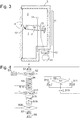
- Fig. 1 shows a combination refrigerator with a cold and a warm storage zone 1, 2, for example a freezer compartment 1 and a normal cooling compartment 2, which are cut out in a heat-insulated body 3 and can each be closed by a door 4.
- An evaporator 5, 6 is assigned to each of the storage zones 1, 2.
- the evaporator 5 of the freezer compartment 1 is a no-frost evaporator that is accommodated in an evaporator chamber 8 separated from the freezer compartment 1 by a partition 7.
- a fan 9 is attached to partition 7 in order to accelerate the exchange of air between the freezer compartment 1 and the evaporator chamber 8.
- the evaporator 6 of the normal refrigerator compartment can be of any type; preferably it is a plate evaporator which is embedded between an inner container of the body 3 and a heat-insulating foam layer surrounding the inner container.
- a refrigerant circuit of the refrigeration device starting from a pressure connection of a compressor 10, the following are connected in series in series: a condenser 11, a throttle point, the evaporator 5, the evaporator 6 and a suction connection of the compressor 10.
- An electronic control unit 12 controls the operation of the compressor 10 and the fan 9 on the basis of measured values that are supplied by temperature sensors 13, 14.
- the temperature sensor 13 is arranged on the warm storage zone 2 in order to deliver a measured value representative of the air temperature prevailing therein.
- the temperature sensor 13 can be mounted remote from the evaporator 6 on a wall of the storage zone; it is typically embedded on a side wall of the storage zone 2 between the inner container and the foam layer.
- the temperature sensor 14 is mounted inside the evaporator chamber 8, preferably in direct physical contact with the evaporator 5, in order to supply a measured value representative of the temperature of the evaporator 5.
- the temperature sensor 14 is mounted on a surface of the evaporator 5 that is swept over by the air circulating through the evaporator chamber 8, for example a lamella. It could also be located on a side of a lamella facing away from such a surface; In one case, as in the other, the temperature that the temperature sensor 14 detects lies between the evaporation temperature of the refrigerant in the interior of the evaporator 5 and the temperature of the air passing over the evaporator 5.
- the latter is generally colder the longer it has the opportunity to give off heat to the evaporator, ie the slower it is circulated by the fan 9.
- the measured temperature is closer to the evaporation temperature, the thicker the layer of frost that is deposited on the evaporator and isolates it from the circulating air.
- Fig. 2 describes a working method of the control unit 12. It is assumed that the compressor 10 is switched off at the beginning of the method. A current measured value T2 of the temperature sensor 13 is read in in step S1 and compared with a switch-on threshold value Tein in step S2. If T2 ⁇ Tein, the compressor 10 remains switched off, an estimated value d for the thickness of the frost layer on the evaporator 6 is updated in any known manner (S3), and after a predetermined waiting time the method returns to step S1.
- the speed of the compressor 10 can be variable; in that case, when the compressor 10 is put into operation, a rotational speed established in a previous iteration of the method is set.
- the fan 9 is put into operation at a speed established in a previous iteration of the method (S5).
- step S6 A check is then made in step S6 to determine whether a waiting time has elapsed since switching on.
- the duration of the waiting time can be fixed or proportional to the layer thickness estimated in step S3 in order to take into account the fact that the time between switching on the compressor and the formation of a stable temperature gradient between the evaporator 5 and the air flowing over it with the thickness the layer of frost increases. If not, the method goes directly to step S12, if so, then a current measured value T1 of the temperature sensor 13 as well as measured values of the speed or power of the fan 9 and, if the compressor 10 can be operated at different non-vanishing speeds, measured values of the speed or power of the compressor 10 is read in (S7).
- the temperature T1 is between the evaporation temperature of the refrigerant in the evaporator 5 and the temperature TI of the air sucked in from the cold storage zone 1. Its value depends on the air temperature TI, the throughput or mass flow of the air through the evaporator chamber (and thus ultimately on the power or speed of the fan 9) and on the throughput or mass flow of the refrigerant (and thus ultimately on the output or speed of the compressor 10), and possibly on the thickness d of Layer of frost on the evaporator 5.
- the relationship between these parameters and the temperature T1 is stored in a table which the control unit 12 accesses. The table can be created using simulation calculations or measurements on a prototype and enables the control unit to estimate the air temperature TI using the measured values read in in step S7 and possibly the layer thickness d (S8).
- T1 can also be measured continuously after switching on the compressor 10, and from a convergence of the measured value observed in the process, it can be concluded that the stable temperature gradient has been reached. At the same time the thickness d of the frost layer can be deduced from the time required for this.
- the air temperature TI calculated in step S8 is compared with a setpoint value or a setpoint interval of the temperature for the storage zone 1 in step S9. If they match the setpoint or interval, the speeds of compressor 10 and fan 9 are ideally matched to one another and remain unchanged. If the air temperature TI is below the setpoint or interval, then the temperature in storage zone 1 is obviously lower than necessary; in this case, in step S10, the cooling capacity allocated to storage zone 1 is reduced; If it is above the setpoint value or interval, then storage zone 1 is too warm and the cooling capacity is increased in step S11.
- step S12 the temperature of the warm storage zone 2 is measured again and compared with a switch-off threshold Tau. If the measured temperature is above the switch-off threshold, then the compressor 10 and fan 9 remain in operation and the method returns to S6. Otherwise, the compressor 10 and fan 9 are switched off in step S13.
- the estimated thickness d of the frost layer is compared with a limit value (S14). If this has not yet been reached, the method goes directly back to step S1; otherwise a defrosting process is carried out beforehand, ie a defrost heater 15 is operated until the temperature of the temperature sensor 14 exceeds a limit value just above 0 ° C., and then the method returns to output S1.
- One possibility of reducing or increasing the cooling output in steps S10 and S11 is to change the output or the speed of the fan 9. The higher this is, the shorter the time in which the air sweeps past the evaporator 10 , and the greater the temperature difference between the air and the boiling temperature of the refrigerant in the evaporator.
- the heat exchange capacity also increases in accordance with the high temperature gradient. I.e. in order to reduce or increase the cooling capacity, it is sufficient to reduce or increment the speed of the fan 9.
- Such a decrement or incrementation can be repeated one or more times during a switch-on phase of the fan 9 in order to adapt the distribution of the cooling capacity to the storage zones 1, 2 to their respective requirements; the speed adjustment can, however, also be distributed over several switch-on phases of the fan 9, since at the beginning of a switch-on phase the fan 9 is put into operation at the target speed that applied at the end of the previous switch-on phase.
- a simple compressor can be used as the compressor 10, which can only be switched between a switched-off state and a switched-on state with a fixed speed.
- the compressor 10 is a compressor with a variable speed
- a change in the cooling capacity can also be brought about by changing the compressor speed.
- An increase in the speed of the compressor leads on the one hand to an increase in the mass flow of the refrigerant, so that more liquid refrigerant is available per unit of time, on the other hand it leads to a reduction in the pressure - and thus the evaporation temperature - in the evaporators 5, 6 If it is assumed that the upstream evaporator 5 is not completely filled with liquid refrigerant, then an increase in the compressor speed leads on the one hand to an increased supply of liquid refrigerant and on the other hand to a reduction in the evaporation temperature.
- Fig. 3 shows a second embodiment of a refrigeration device according to the invention.
- the refrigeration device again has a cold and a warm storage zone 1, 2 in a heat-insulated body 3, but both storage zones are cooled by a common no-frost evaporator 16.
- a flap 17 can be moved under the control of the control unit between two positions in which air can circulate between the evaporator chamber 8 and only one of the storage zones 1, 2.
- Temperature sensors 13, 14 are as in the case of Fig.1 provided on the storage zone 2 or on the evaporator 16.
- Steps S1-S5 of an operation procedure executed by the control unit 12 are the same as in the case of FIG Fig. 2 and will not be described again.
- the flap 17 can assume any of the two positions when the compressor and the fan are started up in S4 and S5; In the following, it is assumed that the position assumed allows circulation only between the evaporator chamber 8 and the warm storage zone 2. By regularly incrementing a counter (S16), the time is measured which is required until the temperature in the storage zone has fallen below Tau again (S17).
- This time i is multiplied by a predetermined factor a in order to determine the subsequent running time of the compressor 10 when the flap 17 is switched to the other position (S18). Then the counter i is at regular time intervals decrements until it reaches the value 0 again (S20).
- the subsequent steps S7 of measuring the temperature T1 by the temperature sensor 14 (S21), calculating the air temperature TI (S8) and comparing (S9) are with those of FIG Fig. 2 identical.
- steps S10 or S11 there are the above-described possibilities of adapting the speed of the fan 9 and / or the compressor 10.
- steps S10, S11 to adapt the factor a, that is to say to increment it if the temperature TI is above the setpoint interval or to decrement it if the temperature TI is below the setpoint interval. Thereafter, the compressor 10 and the fan S9 are turned off for a long time (S13), and the process returns to step S1.
Abstract
Ein Kältegerät hat eine erste und eine zweite Lagerzone (1, 2), einen Kältemittelkreislauf zum Kühlen der beiden Lagerzonen (1, 2) auf unterschiedliche Temperaturen, der einen Verdichter (10) zum Umwälzen eines Kältemittels und wenigstens einen ersten Verdampfer (6; 16) aufweist, der als Wärmetauscher zwischen dem Kältemittel als einem ersten Wärmeträgermedium und Luft als einem zweiten Wärmeträgermedium fungiert, einen Ventilator (9), der angeordnet ist, um die Luft zwischen dem ersten Verdampfer (6; 16) und wenigstens der ersten Lagerzone (1) umzuwälzen, einen an dem ersten Verdampfer (6; 16) angeordneten ersten Temperaturfühler (14), einen von dem ersten Temperaturfühler (14) verschiedenen, an der zweiten Lagerzone (2) angeordneten zweiten Temperaturfühler (13) und eine Steuereinheit (12) zum Steuern der Leistung des Verdichters (10) anhand der vom zweiten Temperaturfühler (13) gemessenen Temperatur (T2) und des Durchsatzes wenigstens eines der Wärmeträgermedien durch den Wärmetauscher anhand der vom ersten Temperaturfühler (14) gemessenen Temperatur (T1).A refrigeration device has a first and a second storage zone (1, 2), a refrigerant circuit for cooling the two storage zones (1, 2) to different temperatures, the one compressor (10) for circulating a refrigerant and at least one first evaporator (6; 16) ), which acts as a heat exchanger between the refrigerant as a first heat transfer medium and air as a second heat transfer medium, a fan (9) which is arranged to circulate the air between the first evaporator (6; 16) and at least the first storage zone (1 ) to circulate, a first temperature sensor (14) arranged on the first evaporator (6; 16), a second temperature sensor (13) arranged on the second storage zone (2), which is different from the first temperature sensor (14) and a control unit (12) for Controlling the performance of the compressor (10) on the basis of the temperature (T2) measured by the second temperature sensor (13) and the throughput of at least one of the heat transfer media through the heat exchanger based on the temperature (T1) measured by the first temperature sensor (14).
Description
Die vorliegende Erfindung betrifft ein Kältegerät, insbesondere Haushaltskältegerät, mit einer ersten und einer zweiten Lagerzone, die auf unterschiedlichen Betriebstemperaturen gehalten werden, typischerweise einem Normalkühlfach und einem Gefrierfach, und ein Verfahren zum Betreiben eines solchen Kältegeräts.The present invention relates to a refrigeration device, in particular a household refrigeration device, with a first and a second storage zone, which are kept at different operating temperatures, typically a normal refrigerator compartment and a freezer compartment, and a method for operating such a refrigeration device.
Aus Kostengründen sind solche Kältegeräte oft als sogenannte Einkreisgeräte ausgeführt, bei denen die verschiedenen Lagerzonen durch in einem Kältemittelkreislauf in Reihe hintereinandergeschaltete Verdampfer gekühlt werden. Aufgrund der Hintereinanderschaltung können die Verdampfer nicht unabhängig voneinander mit Kältemittel versorgt werden, und der Betrieb des Kältemittelkreislaufs kann nur anhand einer einzigen gemessenen Temperatur, im Allgemeinen derjenigen der wärmeren Lagerzone, gesteuert werden. Die Lagerzone des stromabwärtigen Verdampfers kann auf einer niedrigeren Temperatur als die des stromaufwärtigen gehalten werden, indem eine Drosselstelle zwischen den Verdampfern im Betrieb eine Druckdifferenz zwischen den Verdampfern aufrechterhält und so im stromabwärtigen Verdampfer eine niedrigere Verdampfungstemperatur als im stromaufwärtigen bewirkt. Umgekehrt kann eine höhere Temperatur in der Lagerzone des stromabwärtigen Verdampfers erreicht werden, indem der Zufluss an flüssigem Kältemittel zu den Verdampfern so bemessen wird, dass er den Bedarf des stromaufwärtigen Verdampfers knapp deckt, so dass nur noch ein kleiner Rest des ursprünglich in den stromaufwärtigen Verdampfer eingespeisten flüssigen Kältemittels den stromabwärtigen Verdampfer erreicht.For reasons of cost, such refrigeration devices are often designed as so-called single-circuit devices in which the various storage zones are cooled by evaporators connected in series in a refrigerant circuit. Because of the series connection, the evaporators cannot be supplied with refrigerant independently of one another, and the operation of the refrigerant circuit can only be controlled on the basis of a single measured temperature, generally that of the warmer storage zone. The storage zone of the downstream evaporator can be kept at a lower temperature than that of the upstream one by a throttle point between the evaporators maintaining a pressure difference between the evaporators during operation and thus causing a lower evaporating temperature in the downstream evaporator than in the upstream one. Conversely, a higher temperature in the storage zone of the downstream evaporator can be achieved by measuring the inflow of liquid refrigerant to the evaporator so that it just covers the needs of the upstream evaporator, so that only a small amount of what was originally transferred to the upstream evaporator fed liquid refrigerant reaches the downstream evaporator.
Im einen wie im anderen Fall ist das Verhältnis, in dem sich die verfügbare Kühlleistung auf die Lagerzonen verteilt, im Wesentlichen fest. Das tatsächlich benötigte Verteilungsverhältnis ist jedoch in Abhängigkeit von der Umgebungstemperatur variabel. Wenn sich die Umgebungstemperatur der Betriebstemperatur der wärmeren Lagerzone nähert, geht deren Kühlbedarf gegen Null, derjenige der kälteren Lagerzone bleibt aber endlich. Dies hat zur Folge, dass wenn das Kältegerät in einer kalten Umgebung betrieben wird, eine ausreichende Kühlung der kälteren Lagerzone nicht gewährleistet werden kann.In one case as in the other, the ratio in which the available cooling capacity is distributed over the storage zones is essentially fixed. The actually required distribution ratio, however, is variable depending on the ambient temperature. When the ambient temperature approaches the operating temperature of the warmer storage zone, its cooling requirement tends to zero, but that of the colder storage zone remains finite. As a result, if the refrigeration device is operated in a cold environment, adequate cooling of the colder storage zone cannot be guaranteed.
Um diesem Problem abzuhelfen, ist bekannt, eine Heizung in der wärmeren Lagerzone anzubringen und diese bei niedriger Umgebungstemperatur zu betreiben, um so eine zum Kühlen auch der kälteren Lagerzone ausreichende Kühlleistung bereitzustellen. Eine solche Vorgehensweise ist mit den Anforderungen an die Energieeffizienz moderner Kältegeräte nicht mehr vereinbar.In order to remedy this problem, it is known to install a heater in the warmer storage zone and to operate it at a low ambient temperature in order to provide a cooling capacity which is sufficient to also cool the colder storage zone. Such an approach is no longer compatible with the energy efficiency requirements of modern refrigeration appliances.
Bei No-Frost-Kältegeräten muss ein Verdampfer in einer von der von ihm gekühlten Lagerzone abgesetzten Lagerkammer untergebracht sein, damit, wenn der Verdampfer zum Abtauen beheizt wird, die freigesetzte Wärme sich nicht in der Lagerzone ausbreitet. Um im Normalbetrieb die Kühlung der Lagerzone zu gewährleisten, ist ein Ventilator vorgesehen, der Luft zwischen der Lagerzone und der Verdampferkammer umwälzt. Bei derartigen No-Frost-Kältegeräten ist ein Temperaturfühler am Verdampfer angebracht, um einen Anstieg der Temperatur über 0°C zu erfassen, der darauf schließen lässt, dass der Verdampfer vollständig abgetaut ist und die Abtauheizung wieder ausgeschaltet werden kann.In the case of no-frost refrigeration devices, an evaporator must be housed in a storage chamber separate from the storage zone it is cooling, so that the heat released does not spread in the storage zone when the evaporator is heated for defrosting. In order to ensure the cooling of the storage zone during normal operation, a fan is provided which circulates air between the storage zone and the evaporator chamber. In such no-frost refrigeration devices, a temperature sensor is attached to the evaporator to detect a rise in temperature above 0 ° C, which indicates that the evaporator has completely defrosted and the defrost heater can be switched off again.
Aufgabe der vorliegenden Erfindung ist, bei einem Einkreis-Kombinationskältegerät mit wenigstens zwei unterschiedlich temperierten Lagerzonen mit einfachen, preiswerten Mitteln eine hohe Energieeffizienz zu erreichen.The object of the present invention is to achieve high energy efficiency in a single-circuit combination refrigerator with at least two storage zones at different temperatures using simple, inexpensive means.
Die Aufgabe wird gelöst, indem bei einem Kältegerät, insbesondere einem Haushaltskältegerät, mit einer ersten und einer zweiten Lagerzone, einem Kältemittelkreislauf zum Kühlen der beiden Lagerzonen auf unterschiedliche Temperaturen, der einen Verdichter zum Umwälzen eines Kältemittels und wenigstens einen ersten Verdampfer aufweist, der als Wärmetauscher zwischen dem Kältemittel als einem ersten Wärmeträgermedium und Luft als einem zweiten Wärmeträgermedium fungiert, einem Ventilator, der angeordnet ist, um Luft zwischen dem ersten Verdampfer und wenigstens der ersten Lagerzone umzuwälzen, einem an dem ersten Verdampfer angeordneten ersten Temperaturfühler und einem von dem ersten Temperaturfühler verschiedenen, an der zweiten Lagerzone angeordneten zweiten Temperaturfühler einer Steuereinheit nicht nur zum Steuern der Leistung des Verdichters anhand der vom zweiten Temperaturfühler gemessenen Temperatur eingerichtet ist, sondern außerdem eingerichtet ist, den Durchsatz wenigstens eines der Wärmeträgermedien durch den Wärmetauscher anhand der vom ersten Temperaturfühler gemessenen Temperatur zu steuern, und zwar vorzugsweise zwischen mehreren nichtverschwindenden Werten des Durchsatzes zu wählen.The object is achieved in that in a refrigeration device, in particular a domestic refrigeration device, with a first and a second storage zone, a refrigerant circuit for cooling the two storage zones to different temperatures, which has a compressor for circulating a refrigerant and at least one first evaporator, which acts as a heat exchanger acts between the refrigerant as a first heat transfer medium and air as a second heat transfer medium, a fan which is arranged to circulate air between the first evaporator and at least the first storage zone, a first temperature sensor arranged on the first evaporator and one different from the first temperature sensor , arranged at the second storage zone second temperature sensor of a control unit is not only set up to control the performance of the compressor based on the temperature measured by the second temperature sensor, but is also set up to at least one throughput it of the heat transfer media through the To control the heat exchanger on the basis of the temperature measured by the first temperature sensor, preferably to choose between several non-zero values of the throughput.
Die Steuerung der Verdichterleistung anhand des zweiten Temperaturfühlers kann auch dann, wenn der Verdichter bei mehreren nichtverschwindenden Drehzahlen oder Leistungen betreibbar ist, vorzugsweise durch Ein- und Ausschalten des Verdichters erfolgen.The control of the compressor output on the basis of the second temperature sensor can also take place when the compressor can be operated at several non-zero speeds or outputs, preferably by switching the compressor on and off.
Einer ersten Ausgestaltung zufolge kann die Durchsatzsteuerung erfolgen, indem die Steuereinheit die Leistung des Ventilators anhand der vom ersten Temperaturfühler gemessenen Temperatur steuert.According to a first embodiment, the throughput can be controlled by the control unit controlling the output of the fan on the basis of the temperature measured by the first temperature sensor.
Die Attribute "erster" bzw. "zweiter" beinhalten hier wohlgemerkt keine Aussage über eine Reihen- oder Rangfolge der damit bezeichneten Temperaturfühler, Lagerzonen oder Verdampfer, sondern dienen ausschließlich deren eindeutiger Benennung und Unterscheidung. Insbesondere rechtfertigt die Verwendung des Attributs "erster" für einen Gegenstand nicht die Annahme, dass auch ein zweiter Gegenstand dieser Art existieren müsste; von der Existenz eines solchen zweiten Gegenstandes ist im Folgenden nur dann auszugehen, wenn dieser ausdrücklich genannt ist.The attributes "first" or "second" do not contain any information about a series or ranking of the temperature sensors, storage zones or evaporators designated with them, but serve exclusively to clearly name and differentiate them. In particular, the use of the attribute "first" for an object does not justify the assumption that a second object of this type must also exist; The existence of such a second object can only be assumed in the following if it is expressly mentioned.
Der erste Temperaturfühler ist bei einem No-Frost-Kältegerät in der Regel ohnehin vorhanden, um eine automatische Beendigung eines Abtauvorgangs zu bewirken. Dieser Temperaturfühler kann daher im Rahmen der vorliegenden Erfindung einer neuen Nutzung zugeführt werden, ohne dass dies den Aufbau des Kältegeräts verkompliziert oder anderweitig den Fertigungsaufwand erhöht. Indem anhand des Messwerts des ersten Temperaturfühlers die Leistung des Ventilators gesteuert wird, kann die Aufteilung der verfügbaren Kühlleistung auf die Lagerzonen beeinflusst werden, und dadurch kann der Bereich der Umgebungstemperaturen vergrößert werden, in dem gewünschte Temperaturen in beiden Lagerzonen aufrechterhalten werden können.The first temperature sensor is usually already present in a no-frost refrigeration device in order to bring about an automatic termination of a defrosting process. This temperature sensor can therefore be put to a new use within the scope of the present invention without this complicating the structure of the refrigeration device or otherwise increasing the manufacturing costs. By controlling the output of the fan on the basis of the measured value of the first temperature sensor, the distribution of the available cooling output between the storage zones can be influenced, and the range of ambient temperatures can thereby be increased in which the desired temperatures can be maintained in both storage zones.
Um eine gewünschte Kühlleistungsverteilung einzustellen, kann die Steuerschaltung die Leistung des Ventilators über ein Tastverhältnis, d.h. ein Verhältnis von Ein- oder Ausschaltzeiten zur Gesamtbetriebszeit des Ventilators beeinflussen. Bevorzugt ist allerdings, dass die Steuerschaltung eingerichtet ist, die Drehzahl des Ventilators unter mehreren nichtverschwindenden Werten auszuwählen. Zum einen ist das Ein- und Ausschalten des Ventilators oft mit hörbaren Betriebsgeräuschen verbunden, die bei kontinuierlichem Betrieb nicht auftreten, zum anderen erleichtert ein kontinuierlicher Betrieb des Ventilators die Abschätzung der Temperatur der ersten Lagerzone, wie im Folgenden noch genauer erläutert wird.In order to set a desired cooling output distribution, the control circuit can influence the output of the fan via a pulse duty factor, ie a ratio of switch-on or switch-off times to the total operating time of the fan. Is preferred however, that the control circuit is arranged to select the speed of the fan from several non-zero values. On the one hand, switching the fan on and off is often associated with audible operating noises that do not occur during continuous operation; on the other hand, continuous operation of the fan makes it easier to estimate the temperature of the first storage zone, as will be explained in more detail below.
Einer zweiten Ausgestaltung zufolge kann die Steuereinheit eingerichtet sein, den Durchsatz eines Wärmeträgermediums, nämlich des Kältemittels, über die Leistung des Verdichters zu steuern.According to a second embodiment, the control unit can be set up to control the throughput of a heat transfer medium, namely the refrigerant, via the output of the compressor.
Auch die Drehzahl des Verdichters sollte unter mehreren nichtverschwindenden Werten auswählbar sein. So kann zum einen durch Ein- und Ausschalten des Verdichters anhand von Messwerten des zweiten Temperaturfühlers die Kälteerzeugung an den Bedarf der zweiten Lagerzone angepasst werden; indem dann, wenn der Verdichter eingeschaltet ist, eine Auswahl zwischen verschiedenen nichtverschwindenden Drehzahlen stattfindet, kann die Aufteilung der Kühlleistung auf die Lagerzonen beeinflusst werden, denn je höher die Drehzahl, umso größer ist der Druckabfall im Kältemittelkreis und umso niedriger ist die Verdampfungstemperatur im Verdampfer. Wenn Verdampfer von zwei Lagerzonen im Kältemittelkreislauf in Reihe hintereinandergeschaltet sind, kann daher durch Heraufsetzen der Verdichterdrehzahl der Anteil der Kühlleistung, der auf den stromaufwärtigen Verdampfer entfällt, erhöht werden. Solange dieser Verdampfer nicht überläuft, gelangt im Wesentlichen nur Kältemitteldampf in den nachgeschalteten Verdampfer, so dass dessen Kühlleistung nur wenig zunimmt. Ist hingegen der stromaufwärtige Verdampfer so dimensioniert, dass er bei Erhöhen der Verdichterdrehzahl alsbald überläuft, so nimmt der Anteil der verfügbaren Kühlleistung, die auf den stromabwärtigen Verdampfer entfällt, stark zu. D.h. während beim Ventilator eine Drehzahlsteigerung grundsätzlich zu einer stärkeren Kühlung der ersten Lagerzone führt, hängt beim Verdichter die Auswirkung einer Drehzahlsteigerung von den Proportionen der Verdampfer ab.The speed of the compressor should also be selectable from several non-zero values. On the one hand, by switching the compressor on and off using measured values from the second temperature sensor, the generation of cold can be adapted to the requirements of the second storage zone; When the compressor is switched on, a selection takes place between different non-vanishing speeds, the distribution of the cooling capacity to the storage zones can be influenced, because the higher the speed, the greater the pressure drop in the refrigerant circuit and the lower the evaporating temperature in the evaporator. If evaporators from two storage zones are connected in series in the refrigerant circuit, the proportion of the cooling capacity that is allocated to the upstream evaporator can therefore be increased by increasing the compressor speed. As long as this evaporator does not overflow, essentially only refrigerant vapor reaches the downstream evaporator, so that its cooling capacity increases only slightly. If, on the other hand, the upstream evaporator is dimensioned in such a way that it overflows immediately when the compressor speed is increased, then the proportion of the available cooling capacity that is allotted to the downstream evaporator increases sharply. I.e. While an increase in the speed of the fan generally leads to greater cooling of the first storage zone, the effect of an increase in speed on the compressor depends on the proportions of the evaporator.
Auch wenn die vom ersten Temperaturfühler gemessene Temperatur nicht mit der tatsächlichen Temperatur der ersten Lagerzone übereinstimmt, ist sie doch an letztere insoweit gekoppelt, dass sie mit zunehmender Temperatur der Lagerzone zunimmt bzw. bei abnehmender Temperatur der Lagerzone abnimmt. Deswegen sollte die Steuereinheit eingerichtet sein, die Temperatur der ersten Lagerzone anhand der vom ersten Temperaturfühler gemessenen Temperatur und der gemessenen Leistung des Ventilators abzuschätzen und eine Sollleistung des Ventilators heraufzusetzen, wenn die abgeschätzte Temperatur über einem Sollwert liegt bzw. die Solleistung herabzusetzen, wenn die abgeschätzte Temperatur unter einem Sollwert liegt. Der Sollwert kann in beiden Fällen der gleiche sein; vorzugsweise ist er im erstgenannten Fall geringfügig höher als im zweitgenannten, um einen Betrieb des Ventilators ohne ständiges Auf- und Abregeln der Leistung zu ermöglichen.Even if the temperature measured by the first temperature sensor does not match the actual temperature of the first storage zone, it is still linked to the latter in that it increases or decreases with increasing temperature of the storage zone. decreases with decreasing temperature of the storage zone. The control unit should therefore be set up to estimate the temperature of the first storage zone based on the temperature measured by the first temperature sensor and the measured power of the fan and to increase a setpoint power of the fan if the estimated temperature is above a setpoint value or to reduce the setpoint power if the estimated one Temperature is below a setpoint. The setpoint can be the same in both cases; it is preferably slightly higher in the first-mentioned case than in the second-mentioned case, in order to enable the fan to be operated without constantly increasing and decreasing the output.
Je höher die Leistung des Ventilators, umso schneller wird die Luft zwischen der ersten Lagerzone und dem ersten Verdampfer umgewälzt, und umso höher ist deshalb die zu erwartende Abweichung zwischen der vom ersten Temperaturfühler gemessenen Temperatur und der wahren Temperatur der ersten Lagerzone. Dem kann Rechnung getragen werden, indem beim Abschätzen der Temperatur der ersten Lagerzone eine Differenz zwischen dieser und der vom ersten Temperaturfühler gemessenen Temperatur um so höher angenommen wird, je höher die Leistung des Ventilators und/oder des Verdichters ist.The higher the power of the fan, the faster the air is circulated between the first storage zone and the first evaporator, and the higher the expected deviation between the temperature measured by the first temperature sensor and the true temperature of the first storage zone. This can be taken into account in that when estimating the temperature of the first storage zone, a difference between this and the temperature measured by the first temperature sensor is assumed to be higher, the higher the output of the fan and / or the compressor.
Einer bevorzugten Ausgestaltung der Erfindung zufolge ist ein zweiter Verdampfer zum Kühlen der zweiten Lagerzone im Kältemittelkreislauf mit dem ersten Verdampfer in Reihe verbunden.According to a preferred embodiment of the invention, a second evaporator for cooling the second storage zone in the refrigerant circuit is connected in series with the first evaporator.
Dieser zweite Verdampfer kann dem ersten Verdampfer im Kältemittelkreislauf nachgeschaltet sein, um von letzterem den Rest an flüssigem Kältemittel zu empfangen, der in letzterem noch nicht verdampft ist.This second evaporator can be connected downstream of the first evaporator in the refrigerant circuit in order to receive from the latter the remainder of the liquid refrigerant which has not yet evaporated in the latter.
Einer zweiten Ausgestaltung zufolge können beide Lagerzonen durch denselben ersten Verdampfer gekühlt sein. Ein zweiter Verdampfer kann dann entfallen. Stattdessen ist vorzugsweise eine Klappe durch die Steuereinheit zwischen einer Stellung, in der sie die Luftumwälzung zwischen dem ersten Verdampfer und der ersten Lagerzone erlaubt, und einer Stellung, in der sie eine Luftumwälzung zwischen dem ersten Verdampfer und der zweiten Lagerzone erlaubt, umschaltbar, um jeweils nach entsprechend dem mit Hilfe der Temperaturfühler ermittelten Bedarf eine der Lagerzonen mit Kaltluft aus der Verdampferkammer zu versorgen.According to a second embodiment, both storage zones can be cooled by the same first evaporator. A second evaporator can then be omitted. Instead, a flap is preferably switchable by the control unit between a position in which it allows air to circulate between the first evaporator and the first storage zone, and a position in which it allows air to circulate between the first evaporator and the second storage zone, in each case after using the Temperature sensors determined the need to supply one of the storage zones with cold air from the evaporator chamber.
Die Steuereinheit ist vorzugsweise eingerichtet, die Temperatur der ersten Lagerzone anhand der vom ersten Temperaturfühler gemessenen Temperatur und der gemessenen Leistung des Ventilators abzuschätzen. Dabei kann davon ausgegangen werden, dass die Abweichung zwischen der gemessenen Temperatur und der Temperatur der ersten Lagerzone umso größer ist, je stärker der Wärmefluss über den Verdampfer ist.The control unit is preferably set up to estimate the temperature of the first storage zone on the basis of the temperature measured by the first temperature sensor and the measured power of the fan. It can be assumed that the deviation between the measured temperature and the temperature of the first storage zone is greater, the greater the heat flow through the evaporator.
Dem ersten Verdampfer kann eine Abtauheizung zugeordnet sein.A defrost heater can be assigned to the first evaporator.
Die Steuereinheit sollte dann eingerichtet sein, die Abtauheizung abzuschalten, wenn die vom ersten Temperaturfühler gemessene Temperatur über einen Grenzwert, typischerweise knapp über 0°C, steigt.The control unit should then be set up to switch off the defrost heating when the temperature measured by the first temperature sensor rises above a limit value, typically just above 0 ° C.
Da die Platzierung des ersten Temperaturfühlers am ersten Verdampfer fest ist, der Wärmefluss zwischen dem ersten Verdampfer und der umgewälzten Luft aber je nach Menge des Reifs auf dem Verdampfer variiert, wird die Reifmenge auch einen Einfluss auf die vom ersten Temperaturfühler gemessene Temperatur haben. Deswegen sollte die Steuereinheit eingerichtet sein, beim Abschätzen der Temperatur der ersten Lagerzone eine Menge des auf dem ersten Verdampfer abgeschiedenen Reifs zu berücksichtigen. Dies kann auf diversen Wegen geschehen, z.B. kann eine feste Zuwachsrate des Reifs seit dem letzten Abtauen angenommen werden, eine von der Anzahl an Türöffnungen (und der damit verbundenen Zufuhr von Feuchtigkeit zur ersten Lagerzone) verknüpfte Zuwachsrate, die Position einer Oberfläche der Reifschicht kann auf optischem Wege, über einen kapazitiven Näherungsschalter oder dergleichen erfasst werden.Since the placement of the first temperature sensor on the first evaporator is fixed, but the heat flow between the first evaporator and the circulated air varies depending on the amount of frost on the evaporator, the amount of frost will also have an influence on the temperature measured by the first temperature sensor. The control unit should therefore be set up to take into account an amount of the frost deposited on the first evaporator when estimating the temperature of the first storage zone. This can be done in various ways, e.g. A fixed rate of growth of the frost since the last defrosting can be assumed, a rate of growth linked to the number of door openings (and the associated supply of moisture to the first storage zone), the position of a surface of the frost layer can be determined optically, via a capacitive proximity switch or the like can be detected.
Um die mit zunehmender Schichtdicke des Reifs zunehmende Isolationswirkung zu berücksichtigen, sollte insbesondere der Offsetwert umso größer gewählt werden, je länger ein letztes Abtauen des ersten Verdampfers zurückliegt.In order to take into account the increasing insulation effect with increasing layer thickness of the hoop, the offset value in particular should be selected to be larger the longer it has been since the last defrosting of the first evaporator.
Die Aufgabe wird ferner gelöst durch ein Verfahren zum Betreiben eines Kältegeräts mit einer ersten und einer zweiten Lagerzone, einem Kältemittelkreislauf zum Kühlen der beiden Lagerzonen auf unterschiedliche Temperaturen, der einen Verdichter und wenigstens einen ersten Verdampfer aufweist, einem Ventilator, der angeordnet ist, um Luft zwischen dem ersten Verdampfer und wenigstens der ersten Lagerzone umzuwälzen, mit den Schritten:
- a) Messen der Leistung des Ventilators,
- b) anhand der gemessenen Leistung, Abschätzen eines Sollwerts für die vom ersten Temperaturfühler gemessene Temperatur;
- c) Vergleichen der tatsächlich vom ersten Temperaturfühler gemessenen Temperatur mit dem Sollwert; und
- d) Heraufsetzen der Leistung des Ventilators, wenn die gemessene Temperatur höher als der Sollwert ist, und/oder Herabsetzen der Leistung des Ventilators, wenn die gemessene Temperatur niedriger als der Sollwert ist.
- a) measuring the power of the fan,
- b) on the basis of the measured power, estimating a setpoint value for the temperature measured by the first temperature sensor;
- c) comparing the temperature actually measured by the first temperature sensor with the nominal value; and
- d) increasing the output of the fan if the measured temperature is higher than the target value and / or reducing the output of the fan if the measured temperature is lower than the target value.
Weitere Merkmale und Vorteile der Erfindung ergeben sich aus der nachfolgenden Beschreibung von Ausführungsbeispielen unter Bezugnahme auf die beigefügten Zeichnungen. Es zeigen:
- Fig. 1
- einen schematischen Schnitt durch ein Haushaltskältegerät gemäß einer ersten Ausgestaltung der Erfindung;
- Fig. 2
- ein Flussdiagramm eines von einer Steuereinheit des Geräts aus
Fig. 1 ausgeführten Arbeitsverfahrens; - Fig. 3
- einen schematischen Schnitt durch ein Haushaltskältegerät gemäß einer zweiten Ausgestaltung der Erfindung; und
- Fig. 4
- ein Flussdiagramm eines von einer Steuereinheit des Geräts aus
Fig. 3 ausgeführten Arbeitsverfahrens.
- Fig. 1
- a schematic section through a household refrigerator according to a first embodiment of the invention;
- Fig. 2
- a flow chart of one from a control unit of the device
Fig. 1 the work process carried out; - Fig. 3
- a schematic section through a household refrigerator according to a second embodiment of the invention; and
- Fig. 4
- a flow chart of one from a control unit of the device
Fig. 3 performed work process.
In einem Kältemittelkreislauf des Kältegeräts sind ausgehend von einem Druckanschluss eines Verdichters 10 in Reihe hintereinandergeschaltet: ein Verflüssiger 11, eine Drosselstelle, der Verdampfer 5, der Verdampfer 6 und ein Sauganschluss des Verdichters 10.In a refrigerant circuit of the refrigeration device, starting from a pressure connection of a
Eine elektronische Steuereinheit 12 steuert den Betrieb des Verdichters 10 und des Ventilators 9 anhand von Messwerten, die von Temperaturfühlern 13, 14 geliefert werden. Der Temperaturfühler 13 ist an der warmen Lagerzone 2 angeordnet, um einen für die darin herrschende Lufttemperatur repräsentativen Messwert zu liefern. Zu diesem Zweck kann der Temperaturfühler 13 entfernt vom Verdampfer 6 an einer Wand der Lagerzone montiert sein; typischerweise ist er an einer Seitenwand der Lagerzone 2 zwischen Innenbehälter und Schaumstoffschicht eingebettet.An
Der Temperaturfühler 14 ist innerhalb der Verdampferkammer 8, vorzugsweise in unmittelbarem physischem Kontakt mit dem Verdampfer 5, montiert, um einen für die Temperatur des Verdampfers 5 repräsentativen Messwert zu liefern. Typischerweise ist der Temperaturfühler 14 an einer von der durch die Verdampferkammer 8 zirkulierenden Luft überstrichenen Oberfläche, z.B. einer Lamelle, des Verdampfers 5 montiert. Er könnte sich auch an einer von einer solchen Oberfläche abgewandten Seite einer Lamelle befinden; im einen wie im anderen Fall ist liegt die Temperatur, die der Temperaturfühler 14 erfasst, zwischen der Verdampfungstemperatur des Kältemittels im Innern des Verdampfers 5 und der Temperatur der über den Verdampfer 5 hinwegstreichenden Luft. Letztere ist im Allgemeinen umso kälter, je länger sie Gelegenheit hat, Wärme an den Verdampfer abzugeben, d.h. je langsamer sie vom Ventilator 9 umgewälzt wird. Die gemessene Temperatur liegt umso näher an der Verdampfungstemperatur, je dicker eine auf dem Verdampfer niedergeschlagene und ihn von der zirkulierenden Luft isolierende Reifschicht ist.The
Wenn T2>Tein, dann besteht Kühlbedarf in der warmen Lagerzone 2, und der Verdichter 10 wird in Schritt S4 eingeschaltet. Die Drehzahl des Verdichters 10 kann variabel sein; in dem Fall wird bei Inbetriebnahme des Verdichters 10 eine in einer vorhergehenden Iteration des Verfahrens festgelegte Drehzahl eingestellt.If T2> Ton, then there is a need for cooling in the
Gleichzeitig mit dem Verdichter 10 oder kurz danach wird der Ventilator 9 mit einer in einer vorhergehenden Iteration des Verfahrens festgelegten Drehzahl in Betrieb genommen (S5).Simultaneously with the
Anschließend wird in Schritt S6 überprüft, ob seit dem Einschalten eine Wartezeit verstrichen ist. Die Dauer der Wartezeit kann fest vorgegeben oder proportional zur in Schritt S3 abgeschätzten Schichtdicke sein, um der Tatsache Rechnung zu tragen, dass die Zeit zwischen dem Einschalten des Verdichters und der Ausbildung eines stabilen Temperaturgradienten zwischen dem Verdampfer 5 und der darüber strömenden Luft mit der Dicke der Reifschicht zunimmt. Wenn nicht, geht das Verfahren unmittelbar weiter zu Schritt S12, wenn ja, dann werden ein aktueller Messwert T1 des Temperaturfühlers 13 sowie Messwerte von Drehzahl oder Leistung des Ventilators 9 und, sofern der Verdichter 10bei unterschiedlichen nichtverschwindenden Drehzahlen betreibbar ist, Messwerte von Drehzahl oder Leistung des Verdichters 10 eingelesen (S7).A check is then made in step S6 to determine whether a waiting time has elapsed since switching on. The duration of the waiting time can be fixed or proportional to the layer thickness estimated in step S3 in order to take into account the fact that the time between switching on the compressor and the formation of a stable temperature gradient between the
Die Temperatur T1 liegt zwischen der Verdampfungstemperatur des Kältemittels im Verdampfer 5 und der Temperatur TI der aus der kalten Lagerzone 1 angesaugten Luft. Ihr Wert hängt ab von der Lufttemperatur TI, dem Durchsatz oder Massenstrom der Luft durch die Verdampferkammer (und damit letztlich von Leistung oder Drehzahl des Ventilators 9) sowie vom Durchsatz oder Massenstrom des Kältemittels (und damit letztlich von Leistung oder Drehzahl des Verdichters 10), sowie ggf. von der Dicke d der Reifschicht auf dem Verdampfer 5. Der Zusammenhang zwischen diesen Parametern und der Temperatur T1 ist in einer Tabelle hinterlegt, auf die die Steuereinheit 12 zugreift. Die Tabelle kann anhand von Simulationsrechnungen oder von Messungen an einem Prototyp erstellt sein und ermöglicht der Steuereinheit eine Abschätzung der Lufttemperatur TI anhand der in Schritt S7 eingelesenen Messwerte und ggf. der Schichtdicke d (S8).The temperature T1 is between the evaporation temperature of the refrigerant in the
Anstatt zwischen dem Einschalten des Verdichters 10 und dem Erfassen des Messwerts T1 eine Wartezeit einzuhalten, kann T1 auch nach dem Einschalten des Verdichters 10 fortlaufend gemessen werden, und aus einem dabei beobachteten Konvergieren des Messwerts kann gefolgert werden, dass der stabile Temperaturgradient erreicht ist. Gleichzeitig aus der dafür benötigten Zeit auf die Dicke d der Reifschicht geschlossen werden.Instead of observing a waiting time between switching on the
Die in Schritt S8 berechnete Lufttemperatur TI wird in Schritt S9 mit einem Sollwert oder einem Sollintervall der Temperatur für die Lagerzone 1 verglichen. Bei Übereinstimmung mit dem Sollwert oder-intervall sind die Drehzahlen von Verdichter 10 und Ventilator 9 ideal aufeinander abgestimmt und bleiben unverändert. Liegt die Lufttemperatur TI unter dem Sollwert oder-intervall, dann ist offenbar die Temperatur in der Lagerzone 1 niedriger als nötig; in diesem Fall wird in Schritt S10 die auf die Lagerzone 1 entfallende Kühlleistung herabgesetzt; liegt sie über dem Sollwert oder-intervall, dann ist die Lagerzone 1 zu warm, und die Kühlleistung wird in Schritt S11 heraufgesetzt.The air temperature TI calculated in step S8 is compared with a setpoint value or a setpoint interval of the temperature for the
In Schritt S12 wird die Temperatur der warmen Lagerzone 2 erneut gemessen und mit einer Ausschaltschwelle Taus verglichen. Liegt die gemessene Temperatur über der Ausschaltschwelle, dann bleiben Verdichter 10 und Ventilator 9 in Betrieb, und das Verfahren kehrt zurück zu S6 zurück. Anderenfalls werden Verdichter 10 und Ventilator 9 in Schritt S13 ausgeschaltet.In step S12, the temperature of the
Die abgeschätzte Dicke d der Reifschicht wird mit einem Grenzwert verglichen (S14). Ist dieser noch nicht erreicht, geht das Verfahren direkt zurück zu Schritt S1; anderenfalls wird vorher ein Abtauvorgang durchgeführt, d.h. eine Abtauheizung 15 wird solange betrieben, bis die Temperatur des Temperaturfühlers 14 einen Grenzwert knapp über 0°C überschreitet, und anschließend kehrt das Verfahren zum Ausgang S1 zurück.The estimated thickness d of the frost layer is compared with a limit value (S14). If this has not yet been reached, the method goes directly back to step S1; otherwise a defrosting process is carried out beforehand, ie a
Eine Möglichkeit, die Kühlleistung in den Schritten S10 und S11 herab- bzw. heraufzusetzen, ist das Verändern der Leistung bzw. der Drehzahl des Ventilators 9. Je höher diese ist, um so kürzer ist die Zeit, in der die Luft am Verdampfer 10 vorbeistreicht, und umso größer ist die Temperaturdifferenz zwischen der Luft und der Siedetemperatur des Kältemittels im Verdampfer. Entsprechend dem hohen Temperaturgefälle nimmt auch die Wärmeaustauschleistung zu. D.h. um die Kühlleistung herab- bzw. heraufzusetzen, genügt es, die Drehzahl des Ventilators 9 zu de- bzw. inkrementieren. Eine solche De- oder Inkrementierung kann während einer Einschaltphase des Ventilators 9 ein- oder mehrmals wiederholt werden, um die Verteilung der Kühlleistung auf die Lagerzonen 1, 2 an deren jeweiligen Bedarf anzupassen; die Drehzahlanpassung kann sich aber auch auf mehrere Einschaltphasen des Ventilators 9 verteilen, da dieser zu Beginn einer Einschaltphase jeweils mit derjenigen Soll-Drehzahl in Betrieb genommen wird, die an Ende der vorhergehenden Einschaltphase gegolten hat. Als Verdichter 10 kann in diesem Fall ein einfacher Verdichter verwendet werden, der nur zwischen einem Ausschaltzustand und einem Einschaltzustand mit fester Drehzahl umschaltbar ist.One possibility of reducing or increasing the cooling output in steps S10 and S11 is to change the output or the speed of the
Wenn der Verdichter 10 ein Verdichter mit variabler Drehzahl ist, dann kann eine Veränderung der Kühlleistung auch über eine Veränderung der Verdichterdrehzahl herbeigeführt werden. Eine Steigerung der Drehzahl des Verdichters führt einerseits zu einer Erhöhung des Massenstroms des Kältemittels, so dass pro Zeiteinheit mehr flüssiges Kältemittel zur Verfügung steht, zum anderen führt sie zu einer Verringerung des Drucks - und damit der Verdampfungstemperatur - in den Verdampfern 5, 6. D.h., wenn man davon ausgeht, dass der stromaufwärtige Verdampfer 5 nicht vollständig mit flüssigem Kältemittel gefüllt ist, dann führt eine Steigerung der Verdichterdrehzahl einerseits zu einem Mehrangebot an flüssigem Kältemittel, andererseits zu einer Absenkung der Verdampfungstemperatur. Beides hat zur Folge, dass die Kühlleistung des Verdampfers 5 wesentlich schneller mit der Drehzahl des Verdichters 10 zunimmt als die des Verdampfers 6. Deswegen kann das Verfahren der
Wenn allerdings das Mehrangebot an flüssigem Kältemittel so groß wird, dass es den Verdampfer 5 komplett füllt und in den Verdampfer 6 überläuft, dann hat eine weitere Steigerung der Verdichterdrehzahl keinen nennenswerten Einfluss mehr auf die Kühlleistung des Verdampfers 5; stattdessen nimmt die des Verdampfers 6 stark zu. Würde man in diesem Fall bei zu hoher Temperatur T1 die Drehzahl weiter erhöhen, dann würde dies zu einem "Umkippen" des Systems führen; weil immer mehr flüssiges Kältemittel den Verdampfer 6 erreicht und so zu immer kürzeren Einschaltphasen des Verdichters 10 und einer dadurch immer unzureichenderen Kühlung der kalten Lagerzone 1 führt.If, however, the excess supply of liquid refrigerant becomes so great that it completely fills the
Deswegen ist es bevorzugt, beide Ansätze zu kombinieren, indem eine Anpassung der Drehzahl solange beim Ventilator 9 vorgenommen wird, wie dessen Drehzahl in einem vorgegebenen Intervall liegt, und nur bei Erreichen einer Grenze dieses Intervalls auf eine Drehzahlanpassung am Verdichter 10 ausgewichen wird.It is therefore preferred to combine both approaches by adapting the speed of the
Die Schritte S1-S5 eines von der Steuereinheit 12 ausgeführten Arbeitsverfahrens sind dieselben wie im Falle der
Diese Zeit i wird mit einem vorgegebenen Faktor a multipliziert, um die anschließende Laufzeit des Verdichters 10 bei in die jeweils andere Stellung umgeschalteter Klappe 17 festzulegen (S18). Anschließend wird der Zähler i in regelmäßigen Zeitabständen dekrementiert, bis er wieder den Wert 0 erreicht (S20). Die darauf folgenden Schritte S7 des Messens der Temperatur T1 durch den Temperaturfühler 14 (S21), des Berechnens der Lufttemperatur TI (S8) und des Vergleichens (S9) sind mit denen der
- 11
- (kalte) Lagerzone(cold) storage zone
- 22
- (warme) Lagerzone(warm) storage zone
- 33
- KorpusBody
- 44th
- Türdoor
- 55
- VerdampferEvaporator
- 66th
- VerdampferEvaporator
- 77th
- ZwischenwandPartition
- 88th
- VerdampferkammerEvaporation chamber
- 99
- Ventilatorfan
- 1010
- Verdichtercompressor
- 1111
- VerflüssigerCondenser
- 1212
- SteuereinheitControl unit
- 1313
- TemperaturfühlerTemperature sensor
- 1414th
- TemperaturfühlerTemperature sensor
- 1515th
- AbtauheizungDefrost heater
- 1616
- VerdampferEvaporator
- 1717th
- Klappeflap
Claims (14)
Applications Claiming Priority (1)
| Application Number | Priority Date | Filing Date | Title |
|---|---|---|---|
| DE102019202415.7A DE102019202415A1 (en) | 2019-02-22 | 2019-02-22 | Refrigeration device with two temperature zones and operating procedures for them |
Publications (1)
| Publication Number | Publication Date |
|---|---|
| EP3699519A1 true EP3699519A1 (en) | 2020-08-26 |
Family
ID=69423162
Family Applications (1)
| Application Number | Title | Priority Date | Filing Date |
|---|---|---|---|
| EP20154870.8A Pending EP3699519A1 (en) | 2019-02-22 | 2020-01-31 | Refrigeration device with two temperature zones and method of operation for same |
Country Status (2)
| Country | Link |
|---|---|
| EP (1) | EP3699519A1 (en) |
| DE (1) | DE102019202415A1 (en) |
Cited By (1)
| Publication number | Priority date | Publication date | Assignee | Title |
|---|---|---|---|---|
| EP4306887A1 (en) * | 2022-07-13 | 2024-01-17 | Liebherr-Hausgeräte Ochsenhausen GmbH | Refrigeration and/or freezer device |
Citations (3)
| Publication number | Priority date | Publication date | Assignee | Title |
|---|---|---|---|---|
| US6167712B1 (en) * | 1999-02-05 | 2001-01-02 | Samsung Electronics Co., Ltd. | Method for controlling a refrigerator having a direction control valve |
| WO2006124004A1 (en) * | 2005-05-19 | 2006-11-23 | Gorenje Gospodinjski Aparati, D.D. | Regulation of a cooling/freezing apparatus |
| DE102015218452A1 (en) * | 2015-09-25 | 2017-03-30 | BSH Hausgeräte GmbH | Refrigerating appliance with several storage chambers |
-
2019
- 2019-02-22 DE DE102019202415.7A patent/DE102019202415A1/en active Pending
-
2020
- 2020-01-31 EP EP20154870.8A patent/EP3699519A1/en active Pending
Patent Citations (3)
| Publication number | Priority date | Publication date | Assignee | Title |
|---|---|---|---|---|
| US6167712B1 (en) * | 1999-02-05 | 2001-01-02 | Samsung Electronics Co., Ltd. | Method for controlling a refrigerator having a direction control valve |
| WO2006124004A1 (en) * | 2005-05-19 | 2006-11-23 | Gorenje Gospodinjski Aparati, D.D. | Regulation of a cooling/freezing apparatus |
| DE102015218452A1 (en) * | 2015-09-25 | 2017-03-30 | BSH Hausgeräte GmbH | Refrigerating appliance with several storage chambers |
Cited By (1)
| Publication number | Priority date | Publication date | Assignee | Title |
|---|---|---|---|---|
| EP4306887A1 (en) * | 2022-07-13 | 2024-01-17 | Liebherr-Hausgeräte Ochsenhausen GmbH | Refrigeration and/or freezer device |
Also Published As
| Publication number | Publication date |
|---|---|
| DE102019202415A1 (en) | 2020-08-27 |
Similar Documents
| Publication | Publication Date | Title |
|---|---|---|
| EP1636530B1 (en) | Refrigeration device comprising controlled de-humidification | |
| EP2104811B1 (en) | Refrigeration device and method for controlling a refrigeration device | |
| EP3601906A1 (en) | Refrigeration appliance and method for the operation thereof | |
| DE102013223737A1 (en) | Single-circuit refrigerating appliance | |
| DE10235783A1 (en) | Refrigerator with fan and control method therefor | |
| WO2016206938A1 (en) | Refrigeration unit with air humidity monitoring | |
| EP3699519A1 (en) | Refrigeration device with two temperature zones and method of operation for same | |
| EP1332325B1 (en) | Refrigerating device with an automatic defrosting system | |
| EP3601902B1 (en) | Refrigeration appliance and method for the operation thereof | |
| EP2705312A1 (en) | Single-circuit refrigeration device | |
| EP2841856B1 (en) | Single-circuit refrigerator and operating method therefor | |
| EP1813897A2 (en) | Method for regulating a cooling appliance | |
| DE2557794A1 (en) | Refrigerator automatic defrosting control circuit - has series connected phase cutting economiser with frequency reducing counter for reduced energy consumption | |
| EP4051972A1 (en) | Refrigeration appliance comprising a compartment that can be heated and cooled | |
| DE102015218452A1 (en) | Refrigerating appliance with several storage chambers | |
| EP1613907A1 (en) | Method for power regulation of a defroster heater and refrigeration device with integrated defroster heating | |
| EP4168723B1 (en) | Cooling device with a suction tube heat exchanger and method for operating a cooling device with a suction tube heat exchanger | |
| DE2623879A1 (en) | Domestic refrigerator with compartments at different temps. - has single refrigerator plant with non interacting heat absorbers in compartments | |
| DE102010038381A1 (en) | Cold apparatus i.e. household cold apparatus, has storage chambers arranged between inner container and insulation layer, and thermal mass thermally contacted with vaporizer, where thermal mass is designed as plate-like solid body | |
| DE102015211961A1 (en) | Refrigeration appliance and operating method for it | |
| DE102020210411A1 (en) | Defrosting an evaporator of a refrigerator | |
| DE102016202568A1 (en) | Refrigerating appliance with heatable storage chamber | |
| DE2802774A1 (en) | DEFROST DEVICE FOR A REFRIGERATOR WITH A COMPRESSOR DRIVEN REFRIGERATOR | |
| DE102021208510A1 (en) | Method for operating a refrigeration device and refrigeration device with a defrost heater | |
| DE102011085959A1 (en) | Single-circuit refrigerating appliance |
Legal Events
| Date | Code | Title | Description |
|---|---|---|---|
| PUAI | Public reference made under article 153(3) epc to a published international application that has entered the european phase |
Free format text: ORIGINAL CODE: 0009012 |
|
| STAA | Information on the status of an ep patent application or granted ep patent |
Free format text: STATUS: THE APPLICATION HAS BEEN PUBLISHED |
|
| AK | Designated contracting states |
Kind code of ref document: A1 Designated state(s): AL AT BE BG CH CY CZ DE DK EE ES FI FR GB GR HR HU IE IS IT LI LT LU LV MC MK MT NL NO PL PT RO RS SE SI SK SM TR |
|
| AX | Request for extension of the european patent |
Extension state: BA ME |
|
| STAA | Information on the status of an ep patent application or granted ep patent |
Free format text: STATUS: REQUEST FOR EXAMINATION WAS MADE |
|
| 17P | Request for examination filed |
Effective date: 20210226 |
|
| RBV | Designated contracting states (corrected) |
Designated state(s): AL AT BE BG CH CY CZ DE DK EE ES FI FR GB GR HR HU IE IS IT LI LT LU LV MC MK MT NL NO PL PT RO RS SE SI SK SM TR |
|
| STAA | Information on the status of an ep patent application or granted ep patent |
Free format text: STATUS: EXAMINATION IS IN PROGRESS |
|
| 17Q | First examination report despatched |
Effective date: 20231201 |