EP3699516A2 - Method of decomposing cold head and lifting-up jig - Google Patents
Method of decomposing cold head and lifting-up jig Download PDFInfo
- Publication number
- EP3699516A2 EP3699516A2 EP20155519.0A EP20155519A EP3699516A2 EP 3699516 A2 EP3699516 A2 EP 3699516A2 EP 20155519 A EP20155519 A EP 20155519A EP 3699516 A2 EP3699516 A2 EP 3699516A2
- Authority
- EP
- European Patent Office
- Prior art keywords
- lifting
- displacer
- cold head
- jig
- drive unit
- Prior art date
- Legal status (The legal status is an assumption and is not a legal conclusion. Google has not performed a legal analysis and makes no representation as to the accuracy of the status listed.)
- Granted
Links
Images




Classifications
-
- B—PERFORMING OPERATIONS; TRANSPORTING
- B23—MACHINE TOOLS; METAL-WORKING NOT OTHERWISE PROVIDED FOR
- B23P—METAL-WORKING NOT OTHERWISE PROVIDED FOR; COMBINED OPERATIONS; UNIVERSAL MACHINE TOOLS
- B23P15/00—Making specific metal objects by operations not covered by a single other subclass or a group in this subclass
- B23P15/26—Making specific metal objects by operations not covered by a single other subclass or a group in this subclass heat exchangers or the like
-
- F—MECHANICAL ENGINEERING; LIGHTING; HEATING; WEAPONS; BLASTING
- F25—REFRIGERATION OR COOLING; COMBINED HEATING AND REFRIGERATION SYSTEMS; HEAT PUMP SYSTEMS; MANUFACTURE OR STORAGE OF ICE; LIQUEFACTION SOLIDIFICATION OF GASES
- F25B—REFRIGERATION MACHINES, PLANTS OR SYSTEMS; COMBINED HEATING AND REFRIGERATION SYSTEMS; HEAT PUMP SYSTEMS
- F25B9/00—Compression machines, plants or systems, in which the refrigerant is air or other gas of low boiling point
- F25B9/14—Compression machines, plants or systems, in which the refrigerant is air or other gas of low boiling point characterised by the cycle used, e.g. Stirling cycle
- F25B9/145—Compression machines, plants or systems, in which the refrigerant is air or other gas of low boiling point characterised by the cycle used, e.g. Stirling cycle pulse-tube cycle
-
- B—PERFORMING OPERATIONS; TRANSPORTING
- B25—HAND TOOLS; PORTABLE POWER-DRIVEN TOOLS; MANIPULATORS
- B25B—TOOLS OR BENCH DEVICES NOT OTHERWISE PROVIDED FOR, FOR FASTENING, CONNECTING, DISENGAGING, OR HOLDING
- B25B27/00—Hand tools, specially adapted for fitting together or separating parts or objects whether or not involving some deformation, not otherwise provided for
- B25B27/02—Hand tools, specially adapted for fitting together or separating parts or objects whether or not involving some deformation, not otherwise provided for for connecting objects by press fit or detaching same
-
- B—PERFORMING OPERATIONS; TRANSPORTING
- B66—HOISTING; LIFTING; HAULING
- B66C—CRANES; LOAD-ENGAGING ELEMENTS OR DEVICES FOR CRANES, CAPSTANS, WINCHES, OR TACKLES
- B66C1/00—Load-engaging elements or devices attached to lifting or lowering gear of cranes or adapted for connection therewith for transmitting lifting forces to articles or groups of articles
- B66C1/10—Load-engaging elements or devices attached to lifting or lowering gear of cranes or adapted for connection therewith for transmitting lifting forces to articles or groups of articles by mechanical means
- B66C1/22—Rigid members, e.g. L-shaped members, with parts engaging the under surface of the loads; Crane hooks
-
- F—MECHANICAL ENGINEERING; LIGHTING; HEATING; WEAPONS; BLASTING
- F25—REFRIGERATION OR COOLING; COMBINED HEATING AND REFRIGERATION SYSTEMS; HEAT PUMP SYSTEMS; MANUFACTURE OR STORAGE OF ICE; LIQUEFACTION SOLIDIFICATION OF GASES
- F25B—REFRIGERATION MACHINES, PLANTS OR SYSTEMS; COMBINED HEATING AND REFRIGERATION SYSTEMS; HEAT PUMP SYSTEMS
- F25B9/00—Compression machines, plants or systems, in which the refrigerant is air or other gas of low boiling point
- F25B9/14—Compression machines, plants or systems, in which the refrigerant is air or other gas of low boiling point characterised by the cycle used, e.g. Stirling cycle
-
- F—MECHANICAL ENGINEERING; LIGHTING; HEATING; WEAPONS; BLASTING
- F25—REFRIGERATION OR COOLING; COMBINED HEATING AND REFRIGERATION SYSTEMS; HEAT PUMP SYSTEMS; MANUFACTURE OR STORAGE OF ICE; LIQUEFACTION SOLIDIFICATION OF GASES
- F25B—REFRIGERATION MACHINES, PLANTS OR SYSTEMS; COMBINED HEATING AND REFRIGERATION SYSTEMS; HEAT PUMP SYSTEMS
- F25B2309/00—Gas cycle refrigeration machines
- F25B2309/14—Compression machines, plants or systems characterised by the cycle used
- F25B2309/1414—Pulse-tube cycles characterised by pulse tube details
-
- F—MECHANICAL ENGINEERING; LIGHTING; HEATING; WEAPONS; BLASTING
- F25—REFRIGERATION OR COOLING; COMBINED HEATING AND REFRIGERATION SYSTEMS; HEAT PUMP SYSTEMS; MANUFACTURE OR STORAGE OF ICE; LIQUEFACTION SOLIDIFICATION OF GASES
- F25D—REFRIGERATORS; COLD ROOMS; ICE-BOXES; COOLING OR FREEZING APPARATUS NOT OTHERWISE PROVIDED FOR
- F25D19/00—Arrangement or mounting of refrigeration units with respect to devices or objects to be refrigerated, e.g. infrared detectors
- F25D19/006—Thermal coupling structure or interface
Definitions
- a certain embodiment of the present invention relates to a method of decomposing a cold head and to a lifting-up jig.
- a technique in which a mounting structure provided with a sleeve is used in order to mount a cryocooler onto a cryogenic temperature vacuum chamber such as a cryostat has been known.
- a cryogenic temperature vacuum chamber for example, an object to be cooled such as a superconducting coil is accommodated and the object to be cooled is in thermal contact with an end of a sleeve.
- a cold head of the cryocooler is mounted into the sleeve and cools the object to be cooled via the sleeve (for example, Japanese Patent No. 4749661 ).
- cryocooler In a case where the cryocooler is operated for a long period of time, maintenance of the cryocooler may need to be performed periodically. Since the cold head is somewhat movable relative to the sleeve, the cold head and the sleeve being in thermal contact with each other can be separated from each other. The object to be cooled can be maintained at a cryogenic temperature with the temperature of the cold head increased to a temperature suitable for a maintenance operation (for example, room temperature). Since it is not necessary to increase the temperature of the object to be cooled and cool the object to be cooled again for the maintenance of the cryocooler, a time taken for the maintenance of the cryocooler is shortened.
- a maintenance operation for example, room temperature
- a cold head is decomposed.
- a displacer is lifted up together with a displacer drive unit such as a motor and is extracted from a cylinder.
- a main component extracted in such a manner is subjected to maintenance such as replacement of consumable components or the entire component is replaced with a new component.
- the cold head is assembled again.
- the weight of a component to be detached is large.
- a method of decomposing a cold head is provided with a displacer that extends in an axial direction, a cylinder that accommodates the displacer, and a displacer drive unit that is fastened to the cylinder and is connected to the displacer such that the displacer is driven in the axial direction.
- the method includes mounting a lifting-up jig onto the displacer drive unit, unfastening the displacer drive unit and the cylinder from each other, and operating the lifting-up jig such that the displacer drive unit is lifted up from the cylinder together with the displacer.
- a lifting-up jig which is used to discompose a cold head.
- the lifting-up jig includes a lifting-up jig main body that includes a lifting-up bolt hole and a lifting-up bolt that is screwed into the lifting-up bolt hole.
- the lifting-up jig main body is mountable onto a displacer drive unit of the cold head such that the lifting-up bolt is disposed to be parallel to an axial direction of the cold head.
- the lifting-up jig main body is mounted onto the displacer drive unit, the lifting-up bolt is rotatable relative to the lifting-up jig main body with the lifting-up bolt not moving in the axial direction.
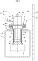
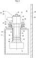
- Figs. 1 and 2 are schematic views for describing an exemplary cryocooler 10 and a mounting structure.
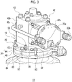
- Figs. 3 and 4 are schematic perspective views illustrating a room temperature portion of the cryocooler 10 shown in Figs. 1 and 2 .
- Figs. 1 and 3 illustrate a state where, for example, the cryocooler 10 is thermally coupled to an object 12 to be cooled such as a superconducting coil and
- Figs. 2 and 4 illustrate a state where the cryocooler 10 and the object 12 to be cooled are thermally uncoupled from each other.
- the mounting structure is a tool for mounting the cryocooler 10 onto a vacuum chamber 14 (for example, cryogenic temperature vacuum chamber such as cryostat) .
- a cooling device that cools the object 12 to be cooled is composed of the cryocooler 10 and the mounting structure.
- the mounting structure may be provided to a buyer together with the cryocooler 10 by a manufacturer of the cryocooler 10.
- the mounting structure is provided with a cold head accommodation sleeve (hereinafter, may be simply referred to as sleeve) 16, a flange interval adjustment mechanism 18, and a flange fastening mechanism 20.
- the cryocooler 10 is provided with a cold head 22 and a compressor 24.
- the sleeve 16 is installed in the vacuum chamber 14 such that a hermetic region 28 isolated from a surrounding environment 26 is formed between the cold head 22 and the sleeve 16.
- the surrounding environment 26 is, for example, an atmospheric pressure environment at a room temperature.
- the hermetic region 28 may be exhausted to form a vacuum and may be filled with an inactive gas such as a helium gas which is not liquefied at a cryogenic temperature.
- the sleeve 16 is installed in the vacuum chamber 14 while being combined with the vacuum chamber 14 such that a vacuum region 30 is defined in the vacuum chamber 14.
- a vacuum region 30 is defined in the vacuum chamber 14.
- an upper end portion of the sleeve 16 is attached to an opening portion formed in a top plate of the vacuum chamber 14 and the sleeve 16 extends to the inside of the vacuum chamber 14 from the opening portion.
- a lower end of the sleeve 16 is attached to the object 12 to be cooled directly or via a predetermined heat transfer member.
- the object 12 to be cooled is disposed in the vacuum region 30.
- the cryocooler 10 is, for example, a single-stage Gifford-McMahon cryocooler (hereinafter, may be referred to as GM cryocooler) . Therefore, the mounting structure is configured such that a single-stage GM cryocooler is mounted onto the vacuum chamber 14.
- the cryocooler 10 is not limited to the single-stage GM cryocooler and may be a two-stage GM cryocooler. In this case, the mounting structure may be configured such that a two-stage GM cryocooler is mounted onto the vacuum chamber 14.
- the cryocooler 10 may be other cryocoolers such as a sterling cryocooler and a pulse tube cryocooler.
- the cold head 22 of the cryocooler 10 is provided with a cold head side cooling stage 32, a cold head side flange 34, and a cylinder 36.
- the cylinder 36 extends along a center axis 38 and connects the cold head side flange 34 to the cold head side cooling stage 32.
- the cold head side flange 34 and the cold head side cooling stage 32 are disposed to be coaxial with the cylinder 36.
- the cold head side flange 34 is provided at an upper end of the cylinder 36 and the cold head side cooling stage 32 is provided at a lower end of the cylinder 36.
- the cylinder 36 is, for example, a hollow cylindrical member.
- the compressor 24 of the cryocooler 10 is provided to circulate a working gas (for example, helium gas) in the cryocooler 10.
- the compressor 24 is configured to supply a high-pressure working gas to the cold head 22, collect a low-pressure working gas, of which the pressure is lowered due to adiabatic expansion at an expansion space in the cold head 22, from the cold head 22, and increase the pressure thereof again.
- the cold head 22 is provided with a high-pressure port 23a serving as a working gas inlet to the cylinder 36 and a low-pressure port 23b serving as a working gas outlet from the cylinder 36.
- the high-pressure port 23a and the low-pressure port 23b are respectively connected to a discharge port and a suction port of the compressor 24 via, for example, pipes such as flexible hoses.
- the cold head 22 is provided with a displacer 40 and a displacer drive unit 42.
- the displacer 40 is disposed in the cylinder 36 to be coaxial with the cylinder 36 and can reciprocate along the cylinder 36 in a direction along the center axis 38.
- the displacer drive unit 42 is fastened to the cylinder 36 and is connected to the displacer 40 to drive the displacer 40 in an axial direction.
- the compressor 24 and the displacer drive unit 42 are disposed in the surrounding environment 26.
- a working gas expansion space is formed between the displacer 40 and the cold head side cooling stage 32.
- the displacer drive unit 42 is configured to alternately switch between supply of a high-pressure working gas from the compressor 24 to the expansion space and collection of a low-pressure working gas from the expansion space to the compressor 24.
- a valve that controls the pressure in the expansion space is built into the displacer drive unit 42. Such a pressure control valve connects the high-pressure port 23a and the low-pressure port 23b to the expansion space in the cylinder 36 alternately.
- a regenerator is built into the displacer 40 and a working gas flows between the compressor 24 and the expansion space via the regenerator.
- the displacer drive unit 42 is configured to appropriately synchronize a change in volume of the expansion space caused by axial reciprocation of the displacer 40 and a change in pressure in the expansion space caused by the pressure control valve with each other. Therefore, the cold head 22 can cool the cold head side cooling stage 32.
- the displacer drive unit 42 is provided with a motor 42a, a drive unit housing 42b, and a front surface cover 42c.
- the drive unit housing 42b has an approximately rectangular parallelepiped shape as a whole.
- the motor 42a is attached to one side surface of the drive unit housing 42b and the front surface cover 42c is attached to a side surface opposite to the one side surface.
- the high-pressure port 23a is connected to the front surface cover 42c.
- the low-pressure port 23b is connected to a side surface different from the above-described two side surfaces.
- the displacer drive unit 42 is fixed to the cold head side flange 34 via fastening members 43 such as bolts, for example. Fastening holes into which the fastening members 43 are inserted penetrate the drive unit housing 42b in a direction from an upper surface to a lower surface and reach the cold head side flange 34.
- the displacer drive unit 42 includes a scotch yoke mechanism that is connected to an output shaft of the motor 42a and is accommodated in the drive unit housing 42b and a displacer driving shaft that connects the scotch yoke mechanism to the displacer 40.
- Rotation of the output shaft of the motor 42a is converted into axial reciprocation of the displacer driving shaft by the scotch yoke mechanism such that the displacer 40 reciprocates in the axial direction.
- the cold head side flange 34 is obtained by coupling two flanges. That is, the cold head side flange 34 is provided with a cylinder top flange 44 that is formed at an upper end opening circumferential edge of the cylinder 36 while being integrated with the cylinder 36 and a transition flange 46 that is attached to a lower surface of the cylinder top flange 44.
- the cylinder top flange 44 can be regarded as a portion of the cylinder 36.
- the transition flange 46 is a member different from the cylinder 36.
- the transition flange 46 includes a flange portion and a short tubular portion that extends downward in the direction along the center axis 38.
- the flange portion is fixed to the lower surface of the cylinder top flange 44 via fastening members such as bolts and the short tubular portion surrounds the upper end of the cylinder 36.
- the inner diameter of the transition flange 46 is slightly larger than the diameter of the cylinder 36 and an inner circumferential surface of the transition flange 46 and an outer circumferential surface of the cylinder 36 are not in contact with each other with a gap interposed therebetween.
- the cold head side cooling stage 32 is a circular plate-shaped member or a short columnar member that is fixed to the cylinder 36 such that a lower end opening of the cylinder 36 is closed.
- the cold head side cooling stage 32 is formed of high thermal conductivity metal such as copper (for example, native copper) or another heat conductive material.
- the cold head side flange 34 and the cylinder 36 are formed of metal such as stainless steel, for example.
- the thermal conductivity of a heat conductive material with which the cold head side cooling stage 32 is formed is higher than the thermal conductivity of a material with which the cylinder 36 (or cold head side flange 34) is formed.
- the sleeve 16 is disposed to be coaxial with the cylinder 36 such that the cylinder 36 is surrounded by the sleeve 16.
- the sleeve 16 is provided with a sleeve side cooling stage 48, a sleeve side flange 50, and a sleeve body 52.
- the sleeve side cooling stage 48 comes into physical contact with the cold head side cooling stage 32 such that the sleeve side cooling stage 48 comes into thermal contact with the cold head side cooling stage 32.
- the plane of contact between the sleeve side cooling stage 48 and the cold head side cooling stage 32 is flat but the shape thereof is not limited thereto.
- the cold head side cooling stage 32 may include a non-planar surface such as a tapered surface, an inclined surface, or an uneven surface and an inner surface of the sleeve side cooling stage 48 that is exposed to the hermetic region 28 may include a non-planar surface corresponding to the non-planar surface described above.
- the object 12 to be cooled is attached to an outer surface of the sleeve side cooling stage 48 that is exposed to the vacuum region 30.
- the cold head side cooling stage 32 comes into physical contact with the sleeve side cooling stage 48, the cold head side cooling stage 32 is thermally coupled to the object 12 to be cooled via the sleeve side cooling stage 48. Accordingly, it is possible to cool the object 12 to be cooled by cooling the cold head side cooling stage 32.
- the cryocooler 10 can cool the object 12 to be cooled to a cryogenic temperature equal to or lower than the critical temperature of a superconducting material.
- the sleeve side flange 50 is coupled to the cold head side flange 34 and is disposed in the surrounding environment 26.
- the sleeve side flange 50 is a short tube that includes flange portions at opposite ends thereof, of which a flange portion on a lower side is fixed to an upper surface of the vacuum chamber 14, and of which a flange portion on an upper side faces the flange portion of the transition flange 46 with an interval of several millimeters provided therebetween, for example.
- a cylindrical portion of the sleeve side flange 50 is disposed outward of a cylindrical portion of the transition flange 46 while being positioned adjacent to the cylindrical portion of the transition flange 46 and both of the cylindrical portions are in contact with each other.
- a sealing member 54 for maintaining the airtightness of the hermetic region 28 is disposed between the cylindrical portion of the sleeve side flange 50 and the cylindrical portion of the transition flange 46.
- the sealing member 54 is, a sealing member such as an O-ring disposed at a circumferential groove formed in a tubular portion of the sleeve side flange 50.
- the sleeve body 52 is a hollow cylindrical member, extends along the center axis 38 to be coaxial with the cylinder 36, and connects the sleeve side flange 50 and the sleeve side cooling stage 48 to each other.
- the sleeve side flange 50 is provided at an upper end of the sleeve body 52 and the sleeve side cooling stage 48 is provided at a lower end of the sleeve body 52.
- the sleeve side flange 50 is an annular member that extends outward in a radial direction perpendicular to the center axis 38 from an upper end opening circumferential edge of the sleeve body 52.
- the sleeve side cooling stage 48 is a circular plate-shaped member or a short columnar member that is fixed to the sleeve body 52 such that a lower end opening of the sleeve body 52 is closed.
- the sleeve side cooling stage 48 is formed of high thermal conductivity metal such as copper (for example, native copper) or another heat conductive material.
- the sleeve side flange 50 and the sleeve body 52 are formed of metal such as stainless steel, for example.
- the thermal conductivity of a heat conductive material with which the sleeve side cooling stage 48 is formed is higher than the thermal conductivity of a material with which the sleeve body 52 (or sleeve side flange 50) is formed.
- the cold head side flange 34 can slide relative to the sleeve side flange 50 in the axial direction and thus the cold head 22 can move relative to the sleeve 16 in the axial direction.
- the movable range thereof is a range of about several millimeters (for example, 2 to 3 millimeters). Since the sealing member 54 is provided, the hermetic region 28 remains isolated from the surrounding environment 26 even at the time of movement of the cold head 22.
- Figs. 1 and 3 illustrate a state where the cold head 22 is positioned at a lower end of the movable range and the cold head side cooling stage 32 and the sleeve side cooling stage 48 are in thermal contact with each other .
- Figs. 2 and 4 illustrate a state where the cold head 22 is positioned at an upper end of the movable range, the cold head side cooling stage 32 and the sleeve side cooling stage 48 are separate from each other such that the cold head side cooling stage 32 and the sleeve side cooling stage 48 are not in thermal contact with each other.
- the flange interval adjustment mechanism 18 is configured to adjust an interval between the sleeve side flange 50 and the cold head side flange 34 such that the cold head side cooling stage 32 and the sleeve side cooling stage 48 come into physical contact with each other or are separated from each other while maintaining isolation of the hermetic region 28 from the surrounding environment 26. A worker can raise or lower the cold head 22 within the movable range by operating the flange interval adjustment mechanism 18.
- the flange interval adjustment mechanism 18 is provided with lifting-up bolt holes 56, formed in the cold head side flange 34 and lifting-up bolts 58 screwed into the lifting-up bolt holes 56.
- the lifting-up bolt holes 56 penetrate the cold head side flange 34 and when the lifting-up bolts 58 are rotated, tip ends of the lifting-up bolts 58 come into contact with the sleeve side flange 50.
- the lifting-up bolts 58 are further rotated in a state where the lifting-up bolts 58 in contact with the sleeve side flange 50, an interval between the sleeve side flange 50 and the cold head side flange 34 is widened.
- the cold head 22 is raised from the sleeve 16 and thus the cold head side cooling stage 32 and the sleeve side cooling stage 48 being in thermal contact with each other are separated from each other as shown in Fig. 2 .
- the lifting-up bolts 58 are rotated reversely, the cold head side cooling stage 32 and the sleeve side cooling stage 48 come into thermal contact with each other again as shown in Fig. 1 .
- the flange fasteningmechanism20 is provided with fastening bolt holes 60 formed in the sleeve side flange 50 and fastening bolts 62 screwed into the fastening bolt holes 60.
- the fastening bolts 62 penetrate both of the cold head side flange 34 and the sleeve side flange 50. However, the fastening bolts 62 are freely fitted into the cold head side flange 34 and thus the fastening bolts 62 are not screwed into the cold head side flange 34.
- the fastening bolts 62 are accommodated into cutout portions 64 formed in the cold head side flange 34.
- the cutout portions 64 are U-shaped grooves that are formed at an outer circumferential edge of the cold head side flange 34 and extend in the axial direction. Head portions of the fastening bolts 62 may come into contact with an upper surface of the cold head side flange 34, that is, the cylinder top flange 44.
- the cold head side flange 34 is fastened to the sleeve side flange 50.
- the fastening bolts 62 are fastened at an appropriate fastening torque, the cold head side cooling stage 32 is pressed against the sleeve side cooling stage 48 tightly such that favorably heat transfer can be made.
- a wall 66 is installed in the vicinity of the cold head 22.
- the wall 66 includes a maintenance window 68.
- the maintenance window 68 is positioned close to the displacer drive unit 42 (for example, positioned laterally close to displacer drive unit 42). Since the wall 66 is present, the worker cannot directly enter a space near the cryocooler 10. However, the worker can insert a hand toward the cryocooler 10 through the maintenance window 68 from the outside of the wall 66. In a situation where a maintenance operation or the like needs to be performed, the worker can manipulate the cryocooler 10 by reaching out to the cryocooler 10 via the maintenance window 68.
- Fig. 5 is a flowchart illustrating a maintenance method for the cryocooler 10.
- a timing at which maintenance of the cryocooler 10 is allowed is reached, a cooling operation of the cryocooler 10 is stopped (S10).
- the worker operates the flange interval adjustment mechanism 18 and the flange fastening mechanism 20 such that the cryocooler 10 and the object 12 to be cooled are thermally uncoupled from each other.
- the cold head side flange 34 and the sleeve side flange 50 coupled to each other by means of the flange fastening mechanism 20 are uncoupled from each other and the cold head 22 is raised by means of the flange interval adjustment mechanism 18. Since the cold head side cooling stage 32 is separated from the sleeve side cooling stage 48, it is possible to increase the temperature of the cold head 22 while maintaining the object 12 to be cooled at a low temperature . Since the sealing member 54 is provided between the cold head side flange 34 and the sleeve side flange 50, isolation of the hermetic region 28 from the surrounding environment 26 is maintained.
- the cooling operation of the cryocooler 10 is restarted (S30).
- the worker operates the flange interval adjustment mechanism 18 and the flange fastening mechanism 20 again such that the cryocooler 10 and the object 12 to be cooled are thermally coupled to each other again. Accordingly, the cryocooler 10 can cool the object 12 to be cooled again.
- a large cold head 22 may be used although depending on the purpose of use of the cryocooler 10.
- the weights of components such as the displacer 40 and the displacer drive unit 42, which are to be detached at the time of maintenance, may also become large and it may not be easy to perform an operation of decomposing the cold head 22.
- the set of jigs includes a lifting-up jig 70.
- the set of jigs may include one or both of a displacer holding jig 80 and a displacer extraction jig 90.
- Fig. 6 is a schematic plan view illustrating the lifting-up jig 70 according to the embodiment.
- the lifting-up jig 70 is provided with a lifting-up jig main body 71 and a lifting-up bolt 72.
- the lifting-up jig main body 71 includes a lifting-up bolt hole 73.
- the lifting-up bolt 72 is screwed into the lifting-up bolt hole 73.
- the lifting-up jig main body 71 is, for example, a plate or a block formed of appropriate metal such as stainless steel or aluminum alloy and has a rectangular shape with an opening provided at the center thereof.
- the lifting-up bolt hole 73 penetrates the lifting-up jig main body 71 in a direction from an upper surface to a lower surface. Accordingly, the lifting-up bolt 72 is inserted in a direction from the upper surface to the lower surface of the lifting-up jig main body 71 and a bolt head portion is positioned above the lifting-up jig main body 71.
- the lifting-up bolt 72 is formed of appropriate metal such as stainless steel.
- a grip portion 74 is fixed to the bolt head portion.
- the grip portion 74 is formed of, for example, resin and the diameter thereof is considerably larger than a bolt diameter. The worker can easily rotate the lifting-up bolt 72 by holding the grip portion 74.
- the lifting-up jig main body 71 is mountable onto the displacer drive unit 42 of the cold head 22 such that the lifting-up bolt 72 is disposed parallel to the axial direction of the cold head 22.
- fastening holes 75 are formed in corner portions of the lifting-up jig main body 71.
- the fastening holes 75 penetrate the lifting-up jig main body 71 in a direction from a front surface to a rear surface. It is possible to fasten the lifting-up jig main body 71 to the displacer drive unit 42 by means of the fastening holes 75 and fastening members (for example, bolts) corresponding thereto.
- the lifting-up jig main body 71 When the lifting-up jig main body 71 is mounted onto the displacer drive unit 42, the lifting-up bolt 72 is rotatable relative to the lifting-up jig main body 71 with the lifting-up bolt 72 not moving in the axial direction.
- the lifting-up jig 70 is provided with a guide portion 76.
- the guide portion 76 is provided with at least one guide rod 77 (for example, two guide rods 77) and a rod support body 78. Two guide rods 77 extend in parallel from the rod support body 78.
- the lifting-up jig main body 71 includes guide holes 79 into which the guide rods 77 are inserted.
- the guide holes 79 are positioned with the lifting-up bolt hole 73 interposed therebetween and penetrate the lifting-up jig main body 71 in a direction from the upper surface to the lower surface.
- the guide rods 77 are inserted into the lifting-up jig main body 71 in a direction from the lower surface to the upper surface and the guide rods 77 extend to be parallel with the lifting-up bolt 72 with the lifting-up bolt 72 interposed therebetween.
- the lifting-up jig main body 71 can slide upward and downward along the guide rods 77.
- the guide portion 76 is formed of a metal material, for example.
- the rod support body 78 is positioned below the lifting-up jig main body 71 and a tip end of the lifting-up bolt 72 abuts the rod support body 78.
- the lifting-up bolt 72 does not move relative to the lifting-up jig main body 71 in the axial direction.
- the lifting-up bolt 72 is rotated in a fastening direction (for example, clockwise direction)
- the lifting-up jigmain body 71 moves upward along the guide rods 77.
- the lifting-up bolt 72 is rotated in a loosening direction (for example, counter-clockwise direction)
- the lifting-up jig main body 71 moves downward along the guide rods 77.
- Fig. 7 is a schematic perspective view illustrating the displacer holding jig 80 according to the embodiment.
- the displacer holding jig 80 is a kind of clamp and is provided with a pair of clamp plates 81 and plate fastening tools 82 such as bolts.
- the displacer holding jig 80 is formed of appropriate metal such as stainless steel or aluminum alloy.
- the clamp plate 81 has an elongated rectangular shape.
- the clamp plate 81 includes fastening holes at opposite ends thereof, with which the plate fastening tools 82 are engaged.
- the plate fastening tools 82 fasten end portions of two clamp plates 81 to each other.
- a central portion of one long side of the clamp plate 81 has an ark shape and a holding material 83 is attached to the ark-shaped portion.
- the holding material 83 comes into contact with a surface of the displacer 40 and is formed of a resin shock absorbing material like a piece of rubber.
- the two clamp plates 81 are disposed to be parallel with each other such that the holding materials 83 face each other.
- Two plate fastening tools 82 fasten the two clamp plates 81 to each other while being positioned with the holding materials 83 interposed therebetween.
- the displacer holding jig 80 is mounted onto the displacer 40. Since the holding materials 83 come into contact with the surface of the displacer 40, the displacer holding jig 80 is less likely to damage the displacer 40. In addition, a frictional force acting between the holding materials 83 and the displacer 40 becomes relatively large and a holding force of the displacer holding jig 80 is also increased.
- Fig. 8 is a schematic perspective view illustrating the displacer extraction jig 90 according to the embodiment.
- the displacer extraction jig 90 is provided with, for example, a rectangular raising plate 91 and several fastening holes 92 are in a central portion thereof .
- the raising plate 91 can be fastened to the displacer 40 by means of corresponding fastening members (for example, bolts).
- the displacer extraction jig 90 is formed of appropriate metal such as stainless steel or aluminum alloy.
- Handles 93 are fixed to the raising plate 91.
- the worker can hold the handles 93 and raise the displacer extraction jig 90 together with the displacer 40.
- the number of the handles 93 is two and the handles 93 are fixed to two facing sides of the raising plate 91, respectively.
- Each handle 93 is positioned above and outward of a side of the raising plate 91 and extends along the side. Since the number of the handles 93 is two, it is easy for the worker to grip the handles 93 with both hands. Alternatively, it is easy for two workers to grip the handles 93 respectively.
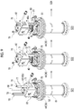
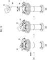
- Figs. 9 and 10 are schematic views illustrating a method of decomposing the cold head 22 according to the embodiment.
- Fig. 9 illustrates the first half of the method of decomposing the cold head 22
- Fig. 10 illustrates the second half of the method of decomposing the cold head 22.
- a lifting-up jig mounting step (S21) includes attaching the lifting-up jig main bodies 71 to the displacer drive unit 42 such that the lifting-up bolts 72 are disposed to be parallel with the axial direction of the cold head 22.
- the motor 42a and the front surface cover 42c are in a state of being attached to the drive unit housing 42b.
- the motor 42a is detached from the drive unit housing 42b and lifting-up jig main body 71 of the lifting-up jig 70 is mounted instead of the motor 42a.
- the front surface cover 42c is detached from the drive unit housing 42b and the lifting-up jig main body 71 of another lifting-up jig 70 is mounted instead of the front surface cover 42c.
- two lifting-up jigs 70 are mounted onto opposite sides of the displacer drive unit 42.
- the guide portion 76 (rod support body 78) of each lifting-up jig 70 is placed on an upper surface of the cylinder top flange 44.
- a lifting-up jig operating step (S22) includes rotating the lifting-up bolts 72 relative to the lifting-up jig main bodies 71 with the lifting-up bolts 72 not moving in the axial direction.
- the lifting-up bolts 72 do not move in the axial direction. Since the lifting-up bolts 72 are screwed into the lifting-up jig main bodies 71, when the lifting-up bolts 72 are rotated in the fastening direction (for example, clockwise direction), the lifting-up jig main bodies 71 move upward along the guide rods 77. Since the lifting-up jig main bodies 71 are attached to the drive unit housing 42b, the displacer drive unit 42 is lifted up from the cylinder 36 together with the displacer 40. By uniformly operating the right and left two lifting-up jigs 70, it is possible to restrain the displacer 40 from being inclined with respect to the cylinder 36 while the displacer 40 is being lifted up.
- the displacer holding jig 80 is mounted onto the displacer 40 (S23).
- the displacer holding jig 80 is mounted onto the displacer 40 such that the displacer 40 is interposed between the two clamp plates 81.
- the clamp plates 81 are placed on the cylinder top flange 44.
- An upper lid 40a of the displacer 40 which is also called an upper cover, is fixed to an end of a displacer drive shaft of the displacer drive unit 42.
- the displacer drive unit 42 is detached from the displacer 40 together with the lifting-up jigs 70 (S24).
- the upper lid 40a of the displacer 40 and the displacer 40 are unfastened from each other and thus it becomes possible to detach the displacer drive unit 42 from the displacer 40.
- the displacer 40 is held by the displacer holding jig 80 in a state of being lifted up from the cylinder 36. Even when the displacer drive unit 42 is detached from the displacer 40, the displacer 40 does not fall into the cylinder 36.
- the displacer extraction jig 90 is mounted onto the displacer 40 (S25). Instead of the upper lid 40a, the displacer extraction jig 90 is attached to the displacer 40. In an example shown in the drawing, the displacer holding jig 80 is detached at this time. However, the displacer holding jig 80 may remain mounted onto the displacer 40.
- the displacer extraction jig 90 is raised together with the displacer 40 and the displacer 40 is extracted from the cylinder 36 (S26).
- the worker can hold the handles 93 and raise the displacer extraction jig 90 together with the displacer 40. In this manner, the displacer 40 is detached from the cold head 22 and the method of decomposing the cold head 22 according to the embodiment is terminated.
- the displacer 40 is subjected to maintenance such as replacement of consumable components.
- the extracted displacer 40 may be replaced with a new displacer.
- the cold head 22 is assembled again.
- the assembly may be performed by performing the above-described operation of decomposing the cold head in a reverse order.
- Fig. 11 is a schematic perspective view illustrating another example of the lifting-up jig 70 according to the embodiment.
- Fig. 12 is a schematic perspective view illustrating a state where the lifting-up jig 70 shown in Fig. 11 is mounted onto the cold head 22.
- the lifting-up jig 70 is provided with the lifting-up jig main body 71 that includes the lifting-up bolt hole 73 and the lifting-up bolt 72 that is screwed into the lifting-up bolt hole 73.
- the lifting-up jig main body 71 is mountable onto the displacer drive unit 42 of the cold head 22 such that the lifting-up bolt 72 is disposed parallel to the axial direction of the cold head 22.
- the lifting-up bolt 72 is rotatable relative to the lifting-up jig main body 71 with the lifting-up bolt 72 not moving in the axial direction.
- the lifting-up jig 70 does not include a guide portion such as a guide rod.
- a guide member 95 for example, may be bolt
- a protection cap 96 is attached to the tip end of the lifting-up bolt 72.
- the protection cap 96 is formed of, for example, resin. The protection cap 96 is caused to abut the cylinder top flange 44 or a surface of a structure near the cylinder top flange 44. Accordingly, the lifting-up bolt 72 does not move in the axial direction. By rotating the lifting-up bolt 72, it is possible to lift up the lifting-up jig main body 71 and the displacer drive unit 42.
- the lifting-up jig 70 is not used. If there is no lifting-up jig 70, it is necessary for the worker to continuously support the weights of the displacer 40 and the displacer drive unit 42 himself or herself when the displacer drive unit 42 is lifted up. In a case where the cold head 22 is large and the displacer 40 or the displacer drive unit 42 is heavy or in a case where a working space is narrow, a burden on the worker performing an operation of decomposing the cold head 22 becomes large.
- the lifting-up jigs 70 are mounted onto the displacer drive unit 42. Therefore, it is possible to support the displacer drive unit 42 with the lifting-up jigs 70 when the displacer drive unit 42 is lifted up. Accordingly, a burden on the worker in an operation of decomposing the cold head 22 is reduced and a workability for maintenance of the cold head 22 is improved.
- the displacer holding jig 80 is used. Even when the displacer 40 and the displacer drive unit 42 are disconnected from each other, the displacer 40 can be maintained in a state of being lifted up from the cylinder 36. Accordingly, the worker does not need to support the displacer 40 by human power such that the displacer 40 does not fall into the cylinder 36. Therefore, a burden on the worker is reduced and a workability for maintenance of the cold head 22 is improved.
- the displacer extraction jig 90 since the displacer extraction jig 90 is used, it is also easy to perform an operation of extracting the displacer 40 from the cylinder 36.
- two lifting-up jigs 70 are used.
- the present invention is not limited thereto. Only one lifting-up jig 70 may also be used. In this case, for example, the lifting-up jig 70 may be mounted onto the drive unit housing 42b instead of the front surface cover 42c and the motor 42a may remain attached to the drive unit housing 42b.
Landscapes
- Engineering & Computer Science (AREA)
- Mechanical Engineering (AREA)
- Physics & Mathematics (AREA)
- Thermal Sciences (AREA)
- General Engineering & Computer Science (AREA)
- Containers, Films, And Cooling For Superconductive Devices (AREA)
- Compressors, Vaccum Pumps And Other Relevant Systems (AREA)
- Cylinder Crankcases Of Internal Combustion Engines (AREA)
- Compressor (AREA)
Abstract
Description
- A certain embodiment of the present invention relates to a method of decomposing a cold head and to a lifting-up jig.
- A technique in which a mounting structure provided with a sleeve is used in order to mount a cryocooler onto a cryogenic temperature vacuum chamber such as a cryostat has been known. In the cryogenic temperature vacuum chamber, for example, an object to be cooled such as a superconducting coil is accommodated and the object to be cooled is in thermal contact with an end of a sleeve. A cold head of the cryocooler is mounted into the sleeve and cools the object to be cooled via the sleeve (for example, Japanese Patent No.
4749661 - In a case where the cryocooler is operated for a long period of time, maintenance of the cryocooler may need to be performed periodically. Since the cold head is somewhat movable relative to the sleeve, the cold head and the sleeve being in thermal contact with each other can be separated from each other. The object to be cooled can be maintained at a cryogenic temperature with the temperature of the cold head increased to a temperature suitable for a maintenance operation (for example, room temperature). Since it is not necessary to increase the temperature of the object to be cooled and cool the object to be cooled again for the maintenance of the cryocooler, a time taken for the maintenance of the cryocooler is shortened.
- At the time of maintenance, a cold head is decomposed. For example, in the case of a GM cryocooler, a displacer is lifted up together with a displacer drive unit such as a motor and is extracted from a cylinder. A main component extracted in such a manner is subjected to maintenance such as replacement of consumable components or the entire component is replaced with a new component. Thereafter, the cold head is assembled again. In the case of a large cold head, the weight of a component to be detached is large. In addition, although depending on an installation environment for the cold head, there may be no sufficient space around the cold head. In such a case, it is difficult to perform an operation of decomposing the cold head and an operation of assembling the cold head.
- It is desirable to improve a workability for maintenance of a cold head.
- According to an aspect of the present invention, there is provided a method of decomposing a cold head. The cold head is provided with a displacer that extends in an axial direction, a cylinder that accommodates the displacer, and a displacer drive unit that is fastened to the cylinder and is connected to the displacer such that the displacer is driven in the axial direction. The method includes mounting a lifting-up jig onto the displacer drive unit, unfastening the displacer drive unit and the cylinder from each other, and operating the lifting-up jig such that the displacer drive unit is lifted up from the cylinder together with the displacer.
- According to another aspect of the present invention, there is provided a lifting-up jig which is used to discompose a cold head. The lifting-up jig includes a lifting-up jig main body that includes a lifting-up bolt hole and a lifting-up bolt that is screwed into the lifting-up bolt hole. The lifting-up jig main body is mountable onto a displacer drive unit of the cold head such that the lifting-up bolt is disposed to be parallel to an axial direction of the cold head. When the lifting-up jig main body is mounted onto the displacer drive unit, the lifting-up bolt is rotatable relative to the lifting-up jig main body with the lifting-up bolt not moving in the axial direction.
- Note that, any combinations of the above constituent elements, and those obtained by substituting the constituent elements or expressions in the invention with each other between methods, devices, systems, or the like are also effective as an aspect of the present invention.
- According to the embodiment of the present invention, it is possible to improve a workability for maintenance of a cold head.
-
-
Fig. 1 is a schematic view for describing an exemplary cryocooler and a mounting structure. -
Fig. 2 is a schematic view for describing the exemplary cryocooler and the mounting structure. -
Fig. 3 is a schematic perspective view illustrating a room temperature portion of the cryocooler shown inFig. 1 . -
Fig. 4 is a schematic perspective view illustrating the room temperature portion of the cryocooler shown inFig. 2 . -
Fig. 5 is a flowchart illustrating a maintenance method for the cryocooler. -
Fig. 6 is a schematic plan view illustrating a lifting-up jig according to an embodiment. -
Fig. 7 is a schematic perspective view illustrating a displacer holding jig according to the embodiment. -
Fig. 8 is a schematic perspective view illustrating a displacer extraction jig according to the embodiment. -
Fig. 9 is a schematic view illustrating a method of decomposing a cold head according to the embodiment. -
Fig. 10 is a schematic view illustrating the method of decomposing the cold head according to the embodiment. -
Fig. 11 is a schematic perspective view illustrating another example of the lifting-up jig according to the embodiment. -
Fig. 12 is a schematic perspective view illustrating a state where the lifting-up jig shown inFig. 11 is mounted onto the cold head. - Hereinafter, an embodiment of the present invention will be described in detail with reference to drawings. Note that, the same reference numerals are assigned to the same or similar constituent elements, members, and processes in the following description and the drawings and repetitive descriptions thereof will be omitted. In addition, the scale or shape of each part in the drawings is set for the sake of convenience of the description and is not to be limitedly interpreted unless otherwise noted. In addition, the embodiment is merely an example and does not limit the scope of the present invention. All of the features described in the embodiment and combinations thereof are not necessarily essential to the invention.
-
Figs. 1 and2 are schematic views for describing anexemplary cryocooler 10 and a mounting structure.Figs. 3 and4 are schematic perspective views illustrating a room temperature portion of thecryocooler 10 shown inFigs. 1 and2 .Figs. 1 and3 illustrate a state where, for example, thecryocooler 10 is thermally coupled to anobject 12 to be cooled such as a superconducting coil andFigs. 2 and4 illustrate a state where thecryocooler 10 and theobject 12 to be cooled are thermally uncoupled from each other. - The mounting structure is a tool for mounting the
cryocooler 10 onto a vacuum chamber 14 (for example, cryogenic temperature vacuum chamber such as cryostat) . A cooling device that cools theobject 12 to be cooled is composed of thecryocooler 10 and the mounting structure. The mounting structure may be provided to a buyer together with thecryocooler 10 by a manufacturer of thecryocooler 10. - The mounting structure is provided with a cold head accommodation sleeve (hereinafter, may be simply referred to as sleeve) 16, a flange
interval adjustment mechanism 18, and aflange fastening mechanism 20. Thecryocooler 10 is provided with acold head 22 and acompressor 24. - The
sleeve 16 is installed in thevacuum chamber 14 such that ahermetic region 28 isolated from a surroundingenvironment 26 is formed between thecold head 22 and thesleeve 16. The surroundingenvironment 26 is, for example, an atmospheric pressure environment at a room temperature. Thehermetic region 28 may be exhausted to form a vacuum and may be filled with an inactive gas such as a helium gas which is not liquefied at a cryogenic temperature. - In addition, the
sleeve 16 is installed in thevacuum chamber 14 while being combined with thevacuum chamber 14 such that avacuum region 30 is defined in thevacuum chamber 14. For example, an upper end portion of thesleeve 16 is attached to an opening portion formed in a top plate of thevacuum chamber 14 and thesleeve 16 extends to the inside of thevacuum chamber 14 from the opening portion. A lower end of thesleeve 16 is attached to theobject 12 to be cooled directly or via a predetermined heat transfer member. Theobject 12 to be cooled is disposed in thevacuum region 30. - The
cryocooler 10 is, for example, a single-stage Gifford-McMahon cryocooler (hereinafter, may be referred to as GM cryocooler) . Therefore, the mounting structure is configured such that a single-stage GM cryocooler is mounted onto thevacuum chamber 14. Thecryocooler 10 is not limited to the single-stage GM cryocooler and may be a two-stage GM cryocooler. In this case, the mounting structure may be configured such that a two-stage GM cryocooler is mounted onto thevacuum chamber 14. Thecryocooler 10 may be other cryocoolers such as a sterling cryocooler and a pulse tube cryocooler. - The
cold head 22 of thecryocooler 10 is provided with a cold headside cooling stage 32, a coldhead side flange 34, and acylinder 36. Thecylinder 36 extends along acenter axis 38 and connects the cold head side flange 34 to the cold headside cooling stage 32. The coldhead side flange 34 and the cold headside cooling stage 32 are disposed to be coaxial with thecylinder 36. The coldhead side flange 34 is provided at an upper end of thecylinder 36 and the cold headside cooling stage 32 is provided at a lower end of thecylinder 36. Thecylinder 36 is, for example, a hollow cylindrical member. - The
compressor 24 of thecryocooler 10 is provided to circulate a working gas (for example, helium gas) in thecryocooler 10. Thecompressor 24 is configured to supply a high-pressure working gas to thecold head 22, collect a low-pressure working gas, of which the pressure is lowered due to adiabatic expansion at an expansion space in thecold head 22, from thecold head 22, and increase the pressure thereof again. Thecold head 22 is provided with a high-pressure port 23a serving as a working gas inlet to thecylinder 36 and a low-pressure port 23b serving as a working gas outlet from thecylinder 36. The high-pressure port 23a and the low-pressure port 23b are respectively connected to a discharge port and a suction port of thecompressor 24 via, for example, pipes such as flexible hoses. - Furthermore, the
cold head 22 is provided with adisplacer 40 and adisplacer drive unit 42. Thedisplacer 40 is disposed in thecylinder 36 to be coaxial with thecylinder 36 and can reciprocate along thecylinder 36 in a direction along thecenter axis 38. Thedisplacer drive unit 42 is fastened to thecylinder 36 and is connected to thedisplacer 40 to drive thedisplacer 40 in an axial direction. Thecompressor 24 and thedisplacer drive unit 42 are disposed in the surroundingenvironment 26. - In the
cylinder 36, a working gas expansion space is formed between thedisplacer 40 and the cold headside cooling stage 32. Thedisplacer drive unit 42 is configured to alternately switch between supply of a high-pressure working gas from thecompressor 24 to the expansion space and collection of a low-pressure working gas from the expansion space to thecompressor 24. A valve that controls the pressure in the expansion space is built into thedisplacer drive unit 42. Such a pressure control valve connects the high-pressure port 23a and the low-pressure port 23b to the expansion space in thecylinder 36 alternately. A regenerator is built into thedisplacer 40 and a working gas flows between thecompressor 24 and the expansion space via the regenerator. - The
displacer drive unit 42 is configured to appropriately synchronize a change in volume of the expansion space caused by axial reciprocation of thedisplacer 40 and a change in pressure in the expansion space caused by the pressure control valve with each other. Therefore, thecold head 22 can cool the cold headside cooling stage 32. - As shown in
Fig. 3 , thedisplacer drive unit 42 is provided with amotor 42a, adrive unit housing 42b, and afront surface cover 42c. Thedrive unit housing 42b has an approximately rectangular parallelepiped shape as a whole. Themotor 42a is attached to one side surface of thedrive unit housing 42b and thefront surface cover 42c is attached to a side surface opposite to the one side surface. The high-pressure port 23a is connected to thefront surface cover 42c. The low-pressure port 23b is connected to a side surface different from the above-described two side surfaces. Thedisplacer drive unit 42 is fixed to the coldhead side flange 34 viafastening members 43 such as bolts, for example. Fastening holes into which thefastening members 43 are inserted penetrate thedrive unit housing 42b in a direction from an upper surface to a lower surface and reach the coldhead side flange 34. - Although not shown, the
displacer drive unit 42 includes a scotch yoke mechanism that is connected to an output shaft of themotor 42a and is accommodated in thedrive unit housing 42b and a displacer driving shaft that connects the scotch yoke mechanism to thedisplacer 40. Rotation of the output shaft of themotor 42a is converted into axial reciprocation of the displacer driving shaft by the scotch yoke mechanism such that thedisplacer 40 reciprocates in the axial direction. - The cold
head side flange 34 is obtained by coupling two flanges. That is, the coldhead side flange 34 is provided with a cylindertop flange 44 that is formed at an upper end opening circumferential edge of thecylinder 36 while being integrated with thecylinder 36 and atransition flange 46 that is attached to a lower surface of the cylindertop flange 44. The cylindertop flange 44 can be regarded as a portion of thecylinder 36. Thetransition flange 46 is a member different from thecylinder 36. - The
transition flange 46 includes a flange portion and a short tubular portion that extends downward in the direction along thecenter axis 38. The flange portion is fixed to the lower surface of the cylindertop flange 44 via fastening members such as bolts and the short tubular portion surrounds the upper end of thecylinder 36. The inner diameter of thetransition flange 46 is slightly larger than the diameter of thecylinder 36 and an inner circumferential surface of thetransition flange 46 and an outer circumferential surface of thecylinder 36 are not in contact with each other with a gap interposed therebetween. - The cold head
side cooling stage 32 is a circular plate-shaped member or a short columnar member that is fixed to thecylinder 36 such that a lower end opening of thecylinder 36 is closed. The cold headside cooling stage 32 is formed of high thermal conductivity metal such as copper (for example, native copper) or another heat conductive material. The coldhead side flange 34 and thecylinder 36 are formed of metal such as stainless steel, for example. The thermal conductivity of a heat conductive material with which the cold headside cooling stage 32 is formed is higher than the thermal conductivity of a material with which the cylinder 36 (or cold head side flange 34) is formed. - The
sleeve 16 is disposed to be coaxial with thecylinder 36 such that thecylinder 36 is surrounded by thesleeve 16. Thesleeve 16 is provided with a sleeveside cooling stage 48, asleeve side flange 50, and asleeve body 52. - The sleeve
side cooling stage 48 comes into physical contact with the cold headside cooling stage 32 such that the sleeveside cooling stage 48 comes into thermal contact with the cold headside cooling stage 32. For example, the plane of contact between the sleeveside cooling stage 48 and the cold headside cooling stage 32 is flat but the shape thereof is not limited thereto. The cold headside cooling stage 32 may include a non-planar surface such as a tapered surface, an inclined surface, or an uneven surface and an inner surface of the sleeveside cooling stage 48 that is exposed to thehermetic region 28 may include a non-planar surface corresponding to the non-planar surface described above. Theobject 12 to be cooled is attached to an outer surface of the sleeveside cooling stage 48 that is exposed to thevacuum region 30. - Therefore, when the cold head
side cooling stage 32 comes into physical contact with the sleeveside cooling stage 48, the cold headside cooling stage 32 is thermally coupled to theobject 12 to be cooled via the sleeveside cooling stage 48. Accordingly, it is possible to cool theobject 12 to be cooled by cooling the cold headside cooling stage 32. For example, in a case where theobject 12 to be cooled is superconducting equipment such as a superconducting coil, thecryocooler 10 can cool theobject 12 to be cooled to a cryogenic temperature equal to or lower than the critical temperature of a superconducting material. - The
sleeve side flange 50 is coupled to the coldhead side flange 34 and is disposed in the surroundingenvironment 26. For example, thesleeve side flange 50 is a short tube that includes flange portions at opposite ends thereof, of which a flange portion on a lower side is fixed to an upper surface of thevacuum chamber 14, and of which a flange portion on an upper side faces the flange portion of thetransition flange 46 with an interval of several millimeters provided therebetween, for example. - A cylindrical portion of the
sleeve side flange 50 is disposed outward of a cylindrical portion of thetransition flange 46 while being positioned adjacent to the cylindrical portion of thetransition flange 46 and both of the cylindrical portions are in contact with each other. A sealingmember 54 for maintaining the airtightness of thehermetic region 28 is disposed between the cylindrical portion of thesleeve side flange 50 and the cylindrical portion of thetransition flange 46. The sealingmember 54 is, a sealing member such as an O-ring disposed at a circumferential groove formed in a tubular portion of thesleeve side flange 50. - The
sleeve body 52 is a hollow cylindrical member, extends along thecenter axis 38 to be coaxial with thecylinder 36, and connects thesleeve side flange 50 and the sleeveside cooling stage 48 to each other. Thesleeve side flange 50 is provided at an upper end of thesleeve body 52 and the sleeveside cooling stage 48 is provided at a lower end of thesleeve body 52. Thesleeve side flange 50 is an annular member that extends outward in a radial direction perpendicular to thecenter axis 38 from an upper end opening circumferential edge of thesleeve body 52. The sleeveside cooling stage 48 is a circular plate-shaped member or a short columnar member that is fixed to thesleeve body 52 such that a lower end opening of thesleeve body 52 is closed. - The sleeve
side cooling stage 48 is formed of high thermal conductivity metal such as copper (for example, native copper) or another heat conductive material. Thesleeve side flange 50 and thesleeve body 52 are formed of metal such as stainless steel, for example. The thermal conductivity of a heat conductive material with which the sleeveside cooling stage 48 is formed is higher than the thermal conductivity of a material with which the sleeve body 52 (or sleeve side flange 50) is formed. - The cold
head side flange 34 can slide relative to thesleeve side flange 50 in the axial direction and thus thecold head 22 can move relative to thesleeve 16 in the axial direction. The movable range thereof is a range of about several millimeters (for example, 2 to 3 millimeters). Since the sealingmember 54 is provided, thehermetic region 28 remains isolated from the surroundingenvironment 26 even at the time of movement of thecold head 22. -
Figs. 1 and3 illustrate a state where thecold head 22 is positioned at a lower end of the movable range and the cold headside cooling stage 32 and the sleeveside cooling stage 48 are in thermal contact with each other .Figs. 2 and4 illustrate a state where thecold head 22 is positioned at an upper end of the movable range, the cold headside cooling stage 32 and the sleeveside cooling stage 48 are separate from each other such that the cold headside cooling stage 32 and the sleeveside cooling stage 48 are not in thermal contact with each other. - The flange
interval adjustment mechanism 18 is configured to adjust an interval between thesleeve side flange 50 and the coldhead side flange 34 such that the cold headside cooling stage 32 and the sleeveside cooling stage 48 come into physical contact with each other or are separated from each other while maintaining isolation of thehermetic region 28 from the surroundingenvironment 26. A worker can raise or lower thecold head 22 within the movable range by operating the flangeinterval adjustment mechanism 18. - As shown in
Figs. 3 and4 , the flangeinterval adjustment mechanism 18 is provided with lifting-up bolt holes 56, formed in the coldhead side flange 34 and lifting-upbolts 58 screwed into the lifting-up bolt holes 56. The lifting-up bolt holes 56 penetrate the coldhead side flange 34 and when the lifting-upbolts 58 are rotated, tip ends of the lifting-upbolts 58 come into contact with thesleeve side flange 50. When the lifting-upbolts 58 are further rotated in a state where the lifting-upbolts 58 in contact with thesleeve side flange 50, an interval between thesleeve side flange 50 and the coldhead side flange 34 is widened. Thecold head 22 is raised from thesleeve 16 and thus the cold headside cooling stage 32 and the sleeveside cooling stage 48 being in thermal contact with each other are separated from each other as shown inFig. 2 . When the lifting-upbolts 58 are rotated reversely, the cold headside cooling stage 32 and the sleeveside cooling stage 48 come into thermal contact with each other again as shown inFig. 1 . - The flange fasteningmechanism20 is provided with fastening bolt holes 60 formed in the
sleeve side flange 50 andfastening bolts 62 screwed into the fastening bolt holes 60. Thefastening bolts 62 penetrate both of the coldhead side flange 34 and thesleeve side flange 50. However, thefastening bolts 62 are freely fitted into the coldhead side flange 34 and thus thefastening bolts 62 are not screwed into the coldhead side flange 34. Thefastening bolts 62 are accommodated intocutout portions 64 formed in the coldhead side flange 34. Thecutout portions 64 are U-shaped grooves that are formed at an outer circumferential edge of the coldhead side flange 34 and extend in the axial direction. Head portions of thefastening bolts 62 may come into contact with an upper surface of the coldhead side flange 34, that is, the cylindertop flange 44. - When the
fastening bolts 62 are fastened, the coldhead side flange 34 is fastened to thesleeve side flange 50. At this time, when thefastening bolts 62 are fastened at an appropriate fastening torque, the cold headside cooling stage 32 is pressed against the sleeveside cooling stage 48 tightly such that favorably heat transfer can be made. - In addition, in an exemplary place of use of the
cryocooler 10, as shown inFig. 1 , awall 66 is installed in the vicinity of thecold head 22. Thewall 66 includes amaintenance window 68. Themaintenance window 68 is positioned close to the displacer drive unit 42 (for example, positioned laterally close to displacer drive unit 42). Since thewall 66 is present, the worker cannot directly enter a space near thecryocooler 10. However, the worker can insert a hand toward thecryocooler 10 through themaintenance window 68 from the outside of thewall 66. In a situation where a maintenance operation or the like needs to be performed, the worker can manipulate thecryocooler 10 by reaching out to thecryocooler 10 via themaintenance window 68. -
Fig. 5 is a flowchart illustrating a maintenance method for thecryocooler 10. When a timing at which maintenance of thecryocooler 10 is allowed is reached, a cooling operation of thecryocooler 10 is stopped (S10). - Immediately before the cooling operation of the
cryocooler 10 is stopped or after the cooling operation of thecryocooler 10 is stopped, the worker operates the flangeinterval adjustment mechanism 18 and theflange fastening mechanism 20 such that thecryocooler 10 and theobject 12 to be cooled are thermally uncoupled from each other. The coldhead side flange 34 and thesleeve side flange 50 coupled to each other by means of theflange fastening mechanism 20 are uncoupled from each other and thecold head 22 is raised by means of the flangeinterval adjustment mechanism 18. Since the cold headside cooling stage 32 is separated from the sleeveside cooling stage 48, it is possible to increase the temperature of thecold head 22 while maintaining theobject 12 to be cooled at a low temperature . Since the sealingmember 54 is provided between the coldhead side flange 34 and thesleeve side flange 50, isolation of thehermetic region 28 from the surroundingenvironment 26 is maintained. - Maintenance of the
cold head 22 is performed (S20). Although details thereof will be described later, thedisplacer drive unit 42 and thedisplacer 40 are detached from thecold head 22. Thecylinder 36 and the cold headside cooling stage 32 remain in thesleeve 16. Then, thedisplacer drive unit 42 and thedisplacer 40 after being subjected to the maintenance (or newdisplacer drive unit 42 and new displacer 40) are attached to thecold head 22. - Then, the cooling operation of the
cryocooler 10 is restarted (S30). After thecryocooler 10 is cooled to a target cooling temperature, the worker operates the flangeinterval adjustment mechanism 18 and theflange fastening mechanism 20 again such that thecryocooler 10 and theobject 12 to be cooled are thermally coupled to each other again. Accordingly, thecryocooler 10 can cool theobject 12 to be cooled again. - Meanwhile, a large
cold head 22 may be used although depending on the purpose of use of thecryocooler 10. The weights of components such as thedisplacer 40 and thedisplacer drive unit 42, which are to be detached at the time of maintenance, may also become large and it may not be easy to perform an operation of decomposing thecold head 22. In addition, there may be no sufficient space around thecold head 22 although depending on an installation environment for thecold head 22. For example, there is a case where it is not easy to access thecold head 22 like a case where the worker needs to insert a hand into themaintenance window 68 to manipulate thecold head 22 as described above. This point also makes an operation of decomposing thecold head 22 difficult. - Therefore, in the present specification, a set of jigs to be used at the time of maintenance of the
cold head 22 will be proposed and description thereof will be made below. In the embodiment, the set of jigs includes a lifting-upjig 70. In addition, the set of jigs may include one or both of adisplacer holding jig 80 and adisplacer extraction jig 90. -
Fig. 6 is a schematic plan view illustrating the lifting-upjig 70 according to the embodiment. The lifting-upjig 70 is provided with a lifting-up jigmain body 71 and a lifting-upbolt 72. The lifting-up jigmain body 71 includes a lifting-upbolt hole 73. The lifting-upbolt 72 is screwed into the lifting-upbolt hole 73. - The lifting-up jig
main body 71 is, for example, a plate or a block formed of appropriate metal such as stainless steel or aluminum alloy and has a rectangular shape with an opening provided at the center thereof. The lifting-upbolt hole 73 penetrates the lifting-up jigmain body 71 in a direction from an upper surface to a lower surface. Accordingly, the lifting-upbolt 72 is inserted in a direction from the upper surface to the lower surface of the lifting-up jigmain body 71 and a bolt head portion is positioned above the lifting-up jigmain body 71. The lifting-upbolt 72 is formed of appropriate metal such as stainless steel. - A
grip portion 74 is fixed to the bolt head portion. Thegrip portion 74 is formed of, for example, resin and the diameter thereof is considerably larger than a bolt diameter. The worker can easily rotate the lifting-upbolt 72 by holding thegrip portion 74. - The lifting-up jig
main body 71 is mountable onto thedisplacer drive unit 42 of thecold head 22 such that the lifting-upbolt 72 is disposed parallel to the axial direction of thecold head 22. As an exemplary configuration for this point, fastening holes 75 are formed in corner portions of the lifting-up jigmain body 71. The fastening holes 75 penetrate the lifting-up jigmain body 71 in a direction from a front surface to a rear surface. It is possible to fasten the lifting-up jigmain body 71 to thedisplacer drive unit 42 by means of the fastening holes 75 and fastening members (for example, bolts) corresponding thereto. - When the lifting-up jig
main body 71 is mounted onto thedisplacer drive unit 42, the lifting-upbolt 72 is rotatable relative to the lifting-up jigmain body 71 with the lifting-upbolt 72 not moving in the axial direction. As an exemplary configuration for this point, the lifting-upjig 70 is provided with aguide portion 76. Theguide portion 76 is provided with at least one guide rod 77 (for example, two guide rods 77) and arod support body 78. Twoguide rods 77 extend in parallel from therod support body 78. The lifting-up jigmain body 71 includes guide holes 79 into which theguide rods 77 are inserted. - The guide holes 79 are positioned with the lifting-up
bolt hole 73 interposed therebetween and penetrate the lifting-up jigmain body 71 in a direction from the upper surface to the lower surface. Theguide rods 77 are inserted into the lifting-up jigmain body 71 in a direction from the lower surface to the upper surface and theguide rods 77 extend to be parallel with the lifting-upbolt 72 with the lifting-upbolt 72 interposed therebetween. The lifting-up jigmain body 71 can slide upward and downward along theguide rods 77. As with the lifting-upjigmain body 71, theguide portion 76 is formed of a metal material, for example. - The
rod support body 78 is positioned below the lifting-up jigmain body 71 and a tip end of the lifting-upbolt 72 abuts therod support body 78. When therod support body 78 is supported by an appropriate supporting surface such as the coldhead side flange 34, the lifting-upbolt 72 does not move relative to the lifting-up jigmain body 71 in the axial direction. When the lifting-upbolt 72 is rotated in a fastening direction (for example, clockwise direction), the lifting-upjigmain body 71 moves upward along theguide rods 77. On the contrary, when the lifting-upbolt 72 is rotated in a loosening direction (for example, counter-clockwise direction), the lifting-up jigmain body 71 moves downward along theguide rods 77. -
Fig. 7 is a schematic perspective view illustrating thedisplacer holding jig 80 according to the embodiment. Thedisplacer holding jig 80 is a kind of clamp and is provided with a pair ofclamp plates 81 andplate fastening tools 82 such as bolts. As with the lifting-upjig 70, thedisplacer holding jig 80 is formed of appropriate metal such as stainless steel or aluminum alloy. For example, theclamp plate 81 has an elongated rectangular shape. Theclamp plate 81 includes fastening holes at opposite ends thereof, with which theplate fastening tools 82 are engaged. Theplate fastening tools 82 fasten end portions of twoclamp plates 81 to each other. - A central portion of one long side of the
clamp plate 81 has an ark shape and a holdingmaterial 83 is attached to the ark-shaped portion. The holdingmaterial 83 comes into contact with a surface of thedisplacer 40 and is formed of a resin shock absorbing material like a piece of rubber. The twoclamp plates 81 are disposed to be parallel with each other such that the holdingmaterials 83 face each other. Twoplate fastening tools 82 fasten the twoclamp plates 81 to each other while being positioned with the holdingmaterials 83 interposed therebetween. - As will be described later, when the
clamp plates 81 are fastened to each other by means of theplate fastening tools 82 such that thedisplacer 40 is interposed between theclamp plates 81, thedisplacer holding jig 80 is mounted onto thedisplacer 40. Since the holdingmaterials 83 come into contact with the surface of thedisplacer 40, thedisplacer holding jig 80 is less likely to damage thedisplacer 40. In addition, a frictional force acting between the holdingmaterials 83 and thedisplacer 40 becomes relatively large and a holding force of thedisplacer holding jig 80 is also increased. -
Fig. 8 is a schematic perspective view illustrating thedisplacer extraction jig 90 according to the embodiment. Thedisplacer extraction jig 90 is provided with, for example, arectangular raising plate 91 andseveral fastening holes 92 are in a central portion thereof . The raisingplate 91 can be fastened to thedisplacer 40 by means of corresponding fastening members (for example, bolts). As with the lifting-upjig 70, thedisplacer extraction jig 90 is formed of appropriate metal such as stainless steel or aluminum alloy. -
Handles 93 are fixed to the raisingplate 91. The worker can hold thehandles 93 and raise thedisplacer extraction jig 90 together with thedisplacer 40. For example, the number of thehandles 93 is two and thehandles 93 are fixed to two facing sides of the raisingplate 91, respectively. Each handle 93 is positioned above and outward of a side of the raisingplate 91 and extends along the side. Since the number of thehandles 93 is two, it is easy for the worker to grip thehandles 93 with both hands. Alternatively, it is easy for two workers to grip thehandles 93 respectively. - Next, a method of decomposing the
cold head 22 by using the above-described jigs will be described. When the cooling operation of thecryocooler 10 is stopped, working gas pipes are detached from the high-pressure port 23a and the low-pressure port 23b. Although the inside of thecold head 22 is filled with working gas, the filling pressure thereof is considerably lower than the atmospheric pressure. Therefore, a gas collection tool is mounted into any of the high-pressure port 23a and the low-pressure port 23b such that the working gas in thecold head 22 is collected and the pressure is decreased to be approximately equal to the atmospheric pressure. Then, as will be described later, the lifting-upjig 70 is mounted onto thedisplacer drive unit 42 and an operation of detaching thedisplacer 40 is started. At this time, thecold head 22 is mounted into thesleeve 16. -
Figs. 9 and10 are schematic views illustrating a method of decomposing thecold head 22 according to the embodiment.Fig. 9 illustrates the first half of the method of decomposing thecold head 22 andFig. 10 illustrates the second half of the method of decomposing thecold head 22. - As shown in
Fig. 9 , the method of decomposing thecold head 22 is started from a step of mounting the lifting-upjigs 70 onto the displacer drive unit 42 (S21). A lifting-up jig mounting step (S21) includes attaching the lifting-up jigmain bodies 71 to thedisplacer drive unit 42 such that the lifting-upbolts 72 are disposed to be parallel with the axial direction of thecold head 22. - As described above, while the
cryocooler 10 is being operated, themotor 42a and thefront surface cover 42c are in a state of being attached to thedrive unit housing 42b. Themotor 42a is detached from thedrive unit housing 42b and lifting-up jigmain body 71 of the lifting-upjig 70 is mounted instead of themotor 42a. In addition, thefront surface cover 42c is detached from thedrive unit housing 42b and the lifting-up jigmain body 71 of another lifting-upjig 70 is mounted instead of thefront surface cover 42c. In this manner, two lifting-upjigs 70 are mounted onto opposite sides of thedisplacer drive unit 42. At this time, the guide portion 76 (rod support body 78) of each lifting-upjig 70 is placed on an upper surface of the cylindertop flange 44. - When the lifting-up
jigs 70 are mounted, thedisplacer drive unit 42 and thecylinder 36 are unfastened from each other. The fastening members 43 (refer toFig. 1 ) are detached and thus thedrive unit housing 42b and the cylindertop flange 44 are unfastened from each other. - Next, the lifting-up
jigs 70 are operated such that thedisplacer drive unit 42 is lifted up from thecylinder 36 together with the displacer 40 (S22). A lifting-up jig operating step (S22) includes rotating the lifting-upbolts 72 relative to the lifting-up jigmain bodies 71 with the lifting-upbolts 72 not moving in the axial direction. - Since the tip ends of the lifting-up
bolts 72 abut therod support bodies 78, the lifting-upbolts 72 do not move in the axial direction. Since the lifting-upbolts 72 are screwed into the lifting-up jigmain bodies 71, when the lifting-upbolts 72 are rotated in the fastening direction (for example, clockwise direction), the lifting-up jigmain bodies 71 move upward along theguide rods 77. Since the lifting-up jigmain bodies 71 are attached to thedrive unit housing 42b, thedisplacer drive unit 42 is lifted up from thecylinder 36 together with thedisplacer 40. By uniformly operating the right and left two lifting-upjigs 70, it is possible to restrain thedisplacer 40 from being inclined with respect to thecylinder 36 while thedisplacer 40 is being lifted up. - Then, the
displacer holding jig 80 is mounted onto the displacer 40 (S23). Thedisplacer holding jig 80 is mounted onto thedisplacer 40 such that thedisplacer 40 is interposed between the twoclamp plates 81. Theclamp plates 81 are placed on the cylindertop flange 44. Anupper lid 40a of thedisplacer 40, which is also called an upper cover, is fixed to an end of a displacer drive shaft of thedisplacer drive unit 42. - As shown in
Fig. 10 , thedisplacer drive unit 42 is detached from thedisplacer 40 together with the lifting-up jigs 70 (S24). Theupper lid 40a of thedisplacer 40 and thedisplacer 40 are unfastened from each other and thus it becomes possible to detach thedisplacer drive unit 42 from thedisplacer 40. - At this time, the
displacer 40 is held by thedisplacer holding jig 80 in a state of being lifted up from thecylinder 36. Even when thedisplacer drive unit 42 is detached from thedisplacer 40, thedisplacer 40 does not fall into thecylinder 36. - The
displacer extraction jig 90 is mounted onto the displacer 40 (S25). Instead of theupper lid 40a, thedisplacer extraction jig 90 is attached to thedisplacer 40. In an example shown in the drawing, thedisplacer holding jig 80 is detached at this time. However, thedisplacer holding jig 80 may remain mounted onto thedisplacer 40. - The
displacer extraction jig 90 is raised together with thedisplacer 40 and thedisplacer 40 is extracted from the cylinder 36 (S26). The worker can hold thehandles 93 and raise thedisplacer extraction jig 90 together with thedisplacer 40. In this manner, thedisplacer 40 is detached from thecold head 22 and the method of decomposing thecold head 22 according to the embodiment is terminated. - The
displacer 40 is subjected to maintenance such as replacement of consumable components. Alternatively, the extracteddisplacer 40 may be replaced with a new displacer. Then, thecold head 22 is assembled again. The assembly may be performed by performing the above-described operation of decomposing the cold head in a reverse order. -
Fig. 11 is a schematic perspective view illustrating another example of the lifting-upjig 70 according to the embodiment.Fig. 12 is a schematic perspective view illustrating a state where the lifting-upjig 70 shown inFig. 11 is mounted onto thecold head 22. - The lifting-up
jig 70 is provided with the lifting-up jigmain body 71 that includes the lifting-upbolt hole 73 and the lifting-upbolt 72 that is screwed into the lifting-upbolt hole 73. The lifting-up jigmain body 71 is mountable onto thedisplacer drive unit 42 of thecold head 22 such that the lifting-upbolt 72 is disposed parallel to the axial direction of thecold head 22. When the lifting-up jigmain body 71 is mounted onto thedisplacer drive unit 42, the lifting-upbolt 72 is rotatable relative to the lifting-up jigmain body 71 with the lifting-upbolt 72 not moving in the axial direction. - However, the lifting-up
jig 70 does not include a guide portion such as a guide rod. Instead, a guide member 95 (for example, may be bolt) functioning as a guide rod is inserted into a fastening hole of thedrive unit housing 42b. In addition, aprotection cap 96 is attached to the tip end of the lifting-upbolt 72. Theprotection cap 96 is formed of, for example, resin. Theprotection cap 96 is caused to abut the cylindertop flange 44 or a surface of a structure near the cylindertop flange 44. Accordingly, the lifting-upbolt 72 does not move in the axial direction. By rotating the lifting-upbolt 72, it is possible to lift up the lifting-up jigmain body 71 and thedisplacer drive unit 42. - In a cold head decomposing method in the related art, the lifting-up
jig 70 is not used. If there is no lifting-upjig 70, it is necessary for the worker to continuously support the weights of thedisplacer 40 and thedisplacer drive unit 42 himself or herself when thedisplacer drive unit 42 is lifted up. In a case where thecold head 22 is large and thedisplacer 40 or thedisplacer drive unit 42 is heavy or in a case where a working space is narrow, a burden on the worker performing an operation of decomposing thecold head 22 becomes large. - However, according to the method of decomposing the
cold head 22 in the embodiment, the lifting-upjigs 70 are mounted onto thedisplacer drive unit 42. Therefore, it is possible to support thedisplacer drive unit 42 with the lifting-upjigs 70 when thedisplacer drive unit 42 is lifted up. Accordingly, a burden on the worker in an operation of decomposing thecold head 22 is reduced and a workability for maintenance of thecold head 22 is improved. - In addition, according to the method of decomposing the
cold head 22 in the embodiment, it is possible to easily lift up thedisplacer 40 and thedisplacer drive unit 42 from thecylinder 36 by means of a simple operation of rotating the lifting-upbolts 72. - Furthermore, the
displacer holding jig 80 is used. Even when thedisplacer 40 and thedisplacer drive unit 42 are disconnected from each other, thedisplacer 40 can be maintained in a state of being lifted up from thecylinder 36. Accordingly, the worker does not need to support thedisplacer 40 by human power such that thedisplacer 40 does not fall into thecylinder 36. Therefore, a burden on the worker is reduced and a workability for maintenance of thecold head 22 is improved. - In addition, since the
displacer extraction jig 90 is used, it is also easy to perform an operation of extracting thedisplacer 40 from thecylinder 36. - Hereinabove, the present invention has been describedbased on the examples. The present invention is not limited to the embodiment and it will be understood by those skilled in the art that various design changes can be made, various modification examples can be implemented, and the modification examples also fall within the scope of the present invention. Various features described in relation to a certain embodiment can be applied to other embodiments. New embodiments resulting from combinations of embodiments and will provide the advantages of the embodiments combined.
- In the above-described embodiment, two lifting-up
jigs 70 are used. However, the present invention is not limited thereto. Only one lifting-upjig 70 may also be used. In this case, for example, the lifting-upjig 70 may be mounted onto thedrive unit housing 42b instead of thefront surface cover 42c and themotor 42a may remain attached to thedrive unit housing 42b. - Based on the embodiment, the present invention has been described with specific words and phrases. However, the embodiment merely shows one aspect of the principles and applications of the present invention and regarding the embodiment, various modification examples and changes of arrangement can be made without departing from the idea of the present invention defined in claims.
-
- 10
- cryocooler
- 22
- cold head
- 36
- cylinder
- 40
- displacer
- 42
- displacer drive unit
- 70
- lifting-up jig
- 71
- lifting-up jig main body
- 72
- lifting-up bolt
- 73
- lifting-up bolt hole
- 80
- displacer holding jig
- 90
- displacer extraction jig
Claims (5)
- A method of decomposing a cold head (22) provided with a displacer (40) that extends in an axial direction, a cylinder (36) that accommodates the displacer (40), and a displacer drive unit (42) that is fastened to the cylinder (36) and is connected to the displacer (40) such that the displacer (40) is driven in the axial direction, the method comprising:mounting a lifting-up jig (70) onto the displacer drive unit (42);unfastening the displacer drive unit (42) and the cylinder (36) from each other; andoperating the lifting-up jig (70) such that the displacer drive unit (42) is lifted up from the cylinder (36) together with the displacer (40).
- The method according to claim 1,wherein the lifting-up jig (70) is provided with a lifting-up jig main body (71) that includes a lifting-up bolt hole (73) and a lifting-up bolt (72) that is screwed into the lifting-up bolt hole (73),wherein the mounting of the lifting-up jig (70) includes attaching the lifting-up jig main body (71) to the displacer drive unit (42) such that the lifting-up bolt (72) is disposed to be parallel to the axial direction of the cold head (22), andwherein the operating of the lifting-up jig (70) includes rotating the lifting-up bolt (72) relative to the lifting-up jig main body (71) with the lifting-up bolt (72) not moving in the axial direction.
- The method according to claim 1 or 2, further comprising:mounting a displacer holding jig (80) onto the displacer (40); anddetaching the displacer drive unit (42) from the displacer (40) together with the lifting-up jig (70),wherein the displacer (40) is held by the displacer holding jig (80) in a state of being lifted up from the cylinder (36) .
- The method according to any one of claims 1 to 3, further comprising:mounting a displacer extraction jig (90) onto the displacer (40); andraising the displacer extraction jig (90) together with the displacer (40) such that the displacer (40) is extracted from the cylinder (36).
- A lifting-up jig (70) which is used to discompose a cold head (22), the lifting-up jig (70) comprising:a lifting-up jig main body (71) that includes a lifting-up bolt hole (73); anda lifting-up bolt (72) that is screwed into the lifting-up bolt hole (73),wherein the lifting-up jig main body (71) is mountable onto a displacer drive unit (42) of the cold head (22) such that the lifting-up bolt (72) is disposed to be parallel to an axial direction of the cold head (22), andwherein, when the lifting-up jig main body (71) is mounted onto the displacer drive unit (42), the lifting-up bolt (72) is rotatable relative to the lifting-up jig main body (71) with the lifting-up bolt (72) not moving in the axial direction.
Applications Claiming Priority (1)
| Application Number | Priority Date | Filing Date | Title |
|---|---|---|---|
| JP2019027743A JP7311275B2 (en) | 2019-02-19 | 2019-02-19 | Cold head disassembly method and jig set |
Publications (3)
| Publication Number | Publication Date |
|---|---|
| EP3699516A2 true EP3699516A2 (en) | 2020-08-26 |
| EP3699516A3 EP3699516A3 (en) | 2020-11-04 |
| EP3699516B1 EP3699516B1 (en) | 2024-05-01 |
Family
ID=69468516
Family Applications (1)
| Application Number | Title | Priority Date | Filing Date |
|---|---|---|---|
| EP20155519.0A Active EP3699516B1 (en) | 2019-02-19 | 2020-02-05 | Method of decomposing cold head |
Country Status (4)
| Country | Link |
|---|---|
| US (1) | US11278994B2 (en) |
| EP (1) | EP3699516B1 (en) |
| JP (1) | JP7311275B2 (en) |
| CN (1) | CN111571517B (en) |
Cited By (2)
| Publication number | Priority date | Publication date | Assignee | Title |
|---|---|---|---|---|
| CN115611135A (en) * | 2022-09-20 | 2023-01-17 | 山西江淮重工有限责任公司 | Heat treatment lifting appliance for automatically injecting cooling liquid into inner cavity |
| EP4579142A4 (en) * | 2022-08-24 | 2025-12-10 | Sumitomo Heavy Industries | DISASSEMBLY PROCEDURE FOR A TWO-STAGE COLD HEAD AND DISPLACER REMOVAL DEVICE |
Families Citing this family (4)
| Publication number | Priority date | Publication date | Assignee | Title |
|---|---|---|---|---|
| WO2022060913A2 (en) * | 2020-09-15 | 2022-03-24 | Clemenzi Richard A | Modular encapsulated heat pumps |
| US12313320B2 (en) | 2021-07-08 | 2025-05-27 | Maybell Quantum Industries, Inc. | Integrated dilution refrigerators |
| CN113526324B (en) * | 2021-07-09 | 2023-06-16 | 铜陵铁科轨道装备有限公司 | Lifting appliance for dismounting and mounting large-caliber piston cylinder of automatic dumping car and use method thereof |
| JP2024006360A (en) * | 2022-07-01 | 2024-01-17 | 住友重機械工業株式会社 | cryogenic refrigerator |
Citations (1)
| Publication number | Priority date | Publication date | Assignee | Title |
|---|---|---|---|---|
| JP4749661B2 (en) | 2003-10-15 | 2011-08-17 | 住友重機械工業株式会社 | Refrigerator mounting structure and maintenance method of superconducting magnet device for single crystal pulling device |
Family Cites Families (13)
| Publication number | Priority date | Publication date | Assignee | Title |
|---|---|---|---|---|
| US5072981A (en) * | 1990-10-26 | 1991-12-17 | The United States Of America, As Represented By The Secretary Of Agriculture | Soil moisture tube extraction device |
| CN2163719Y (en) * | 1993-05-26 | 1994-05-04 | 孙桃园 | Multi-functional top-grasping combination tool |
| CN2598978Y (en) * | 2003-01-27 | 2004-01-14 | 周秋平 | Jack |
| JP5014097B2 (en) | 2007-12-10 | 2012-08-29 | 中国電力株式会社 | Packing follower removal tool |
| JP5819582B2 (en) | 2009-09-17 | 2015-11-24 | 株式会社泉精器製作所 | Pipe drawing tool |
| CN202174544U (en) * | 2011-02-25 | 2012-03-28 | 宝山钢铁股份有限公司 | Dismounting tool for laser source RF polar tube |
| JP5784517B2 (en) * | 2012-02-01 | 2015-09-24 | 住友重機械工業株式会社 | Refrigerator mounting structure |
| JP6180349B2 (en) * | 2014-03-18 | 2017-08-16 | 住友重機械工業株式会社 | Cryogenic refrigerator and control method of cryogenic refrigerator |
| EP3037746B1 (en) * | 2014-12-22 | 2020-08-12 | Sumitomo Heavy Industries, Ltd. | Cryocooler and operation method of cryocooler |
| CN204414004U (en) * | 2015-01-14 | 2015-06-24 | 宁波市鄞州东宁工具有限公司 | The drawbench of the auxiliary boosting-rod of band |
| JP2016179519A (en) | 2015-03-23 | 2016-10-13 | 佐藤工業株式会社 | Knock pin removal jig |
| CN207953737U (en) * | 2018-03-12 | 2018-10-12 | 邢台晶龙电子材料有限公司 | Horse is drawn in bearing housing handling |
| JP6902004B2 (en) * | 2018-09-03 | 2021-07-14 | ジャパンスーパーコンダクタテクノロジー株式会社 | Cooling container to which the refrigerator is installed |
-
2019
- 2019-02-19 JP JP2019027743A patent/JP7311275B2/en active Active
-
2020
- 2020-02-05 EP EP20155519.0A patent/EP3699516B1/en active Active
- 2020-02-11 CN CN202010086484.1A patent/CN111571517B/en active Active
- 2020-02-18 US US16/794,202 patent/US11278994B2/en active Active
Patent Citations (1)
| Publication number | Priority date | Publication date | Assignee | Title |
|---|---|---|---|---|
| JP4749661B2 (en) | 2003-10-15 | 2011-08-17 | 住友重機械工業株式会社 | Refrigerator mounting structure and maintenance method of superconducting magnet device for single crystal pulling device |
Cited By (2)
| Publication number | Priority date | Publication date | Assignee | Title |
|---|---|---|---|---|
| EP4579142A4 (en) * | 2022-08-24 | 2025-12-10 | Sumitomo Heavy Industries | DISASSEMBLY PROCEDURE FOR A TWO-STAGE COLD HEAD AND DISPLACER REMOVAL DEVICE |
| CN115611135A (en) * | 2022-09-20 | 2023-01-17 | 山西江淮重工有限责任公司 | Heat treatment lifting appliance for automatically injecting cooling liquid into inner cavity |
Also Published As
| Publication number | Publication date |
|---|---|
| CN111571517B (en) | 2022-07-26 |
| US20200262013A1 (en) | 2020-08-20 |
| JP2020134006A (en) | 2020-08-31 |
| US11278994B2 (en) | 2022-03-22 |
| EP3699516B1 (en) | 2024-05-01 |
| EP3699516A3 (en) | 2020-11-04 |
| JP7311275B2 (en) | 2023-07-19 |
| CN111571517A (en) | 2020-08-25 |
Similar Documents
| Publication | Publication Date | Title |
|---|---|---|
| EP3699516B1 (en) | Method of decomposing cold head | |
| US8756941B2 (en) | Apparatus and methods for improving vibration isolation, thermal dampening, and optical access in cryogenic refrigerators | |
| CN111183326B (en) | Installation structure and installation method of ultra-low temperature refrigerator | |
| CN110858509A (en) | Superconducting magnet cooling device and superconducting magnet cooling method | |
| CN113375359A (en) | Cryogenic refrigerator and cryogenic system | |
| US4979368A (en) | Miniature integral stirling cryocooler | |
| US20230104504A1 (en) | Cooling device and cold head replacement method | |
| EP4549838A1 (en) | Cryogenic refrigerator | |
| JP2007080698A (en) | Sample analyzer | |
| WO2023276856A1 (en) | Cold head mounting structure and cryogenic device | |
| EP3699426B1 (en) | Linear compressor for cryocooler | |
| JP2021169874A (en) | Fitting structure for cryogenic refrigeration machine and cryogenic refrigeration machine | |
| EP4579142A1 (en) | Disassembly method for two-stage cold head, and displacer removal jig | |
| EP4446671B1 (en) | Method for disassembling cryogenic freezer | |
| EP4481300A1 (en) | Gas replacement method for expander of cryocooler, cryocooler, and gas replacement pipe | |
| EP4502499B1 (en) | Method for operating cryogenic refrigerator | |
| WO2019098128A1 (en) | Cryogenic refrigerator | |
| JP2024056390A (en) | Cold head attachment structure, cryogenic temperature device, cold head and maintenance method of cold head | |
| JP7654508B2 (en) | Cryogenic Equipment | |
| JP2025099297A (en) | Temperature rise method for cryogenic device, and cryogenic device |
Legal Events
| Date | Code | Title | Description |
|---|---|---|---|
| PUAI | Public reference made under article 153(3) epc to a published international application that has entered the european phase |
Free format text: ORIGINAL CODE: 0009012 |
|
| STAA | Information on the status of an ep patent application or granted ep patent |
Free format text: STATUS: REQUEST FOR EXAMINATION WAS MADE |
|
| 17P | Request for examination filed |
Effective date: 20200205 |
|
| AK | Designated contracting states |
Kind code of ref document: A2 Designated state(s): AL AT BE BG CH CY CZ DE DK EE ES FI FR GB GR HR HU IE IS IT LI LT LU LV MC MK MT NL NO PL PT RO RS SE SI SK SM TR |
|
| AX | Request for extension of the european patent |
Extension state: BA ME |
|
| PUAL | Search report despatched |
Free format text: ORIGINAL CODE: 0009013 |
|
| STAA | Information on the status of an ep patent application or granted ep patent |
Free format text: STATUS: EXAMINATION IS IN PROGRESS |
|
| AK | Designated contracting states |
Kind code of ref document: A3 Designated state(s): AL AT BE BG CH CY CZ DE DK EE ES FI FR GB GR HR HU IE IS IT LI LT LU LV MC MK MT NL NO PL PT RO RS SE SI SK SM TR |
|
| AX | Request for extension of the european patent |
Extension state: BA ME |
|
| RIC1 | Information provided on ipc code assigned before grant |
Ipc: F25B 9/14 20060101AFI20200930BHEP Ipc: F25D 19/00 20060101ALN20200930BHEP |
|
| 17Q | First examination report despatched |
Effective date: 20201016 |
|
| GRAP | Despatch of communication of intention to grant a patent |
Free format text: ORIGINAL CODE: EPIDOSNIGR1 |
|
| STAA | Information on the status of an ep patent application or granted ep patent |
Free format text: STATUS: GRANT OF PATENT IS INTENDED |
|
| RIC1 | Information provided on ipc code assigned before grant |
Ipc: F25D 19/00 20060101ALN20231122BHEP Ipc: F25B 9/14 20060101AFI20231122BHEP |
|
| INTG | Intention to grant announced |
Effective date: 20231211 |
|
| GRAS | Grant fee paid |
Free format text: ORIGINAL CODE: EPIDOSNIGR3 |
|
| GRAA | (expected) grant |
Free format text: ORIGINAL CODE: 0009210 |
|
| STAA | Information on the status of an ep patent application or granted ep patent |
Free format text: STATUS: THE PATENT HAS BEEN GRANTED |
|
| AK | Designated contracting states |
Kind code of ref document: B1 Designated state(s): AL AT BE BG CH CY CZ DE DK EE ES FI FR GB GR HR HU IE IS IT LI LT LU LV MC MK MT NL NO PL PT RO RS SE SI SK SM TR |
|
| REG | Reference to a national code |
Ref country code: GB Ref legal event code: FG4D |
|
| REG | Reference to a national code |
Ref country code: CH Ref legal event code: EP |
|
| REG | Reference to a national code |
Ref country code: IE Ref legal event code: FG4D |
|
| REG | Reference to a national code |
Ref country code: DE Ref legal event code: R096 Ref document number: 602020029863 Country of ref document: DE |
|
| REG | Reference to a national code |
Ref country code: NL Ref legal event code: FP |
|
| REG | Reference to a national code |
Ref country code: LT Ref legal event code: MG9D |
|
| PG25 | Lapsed in a contracting state [announced via postgrant information from national office to epo] |
Ref country code: IS Free format text: LAPSE BECAUSE OF FAILURE TO SUBMIT A TRANSLATION OF THE DESCRIPTION OR TO PAY THE FEE WITHIN THE PRESCRIBED TIME-LIMIT Effective date: 20240901 |
|
| PG25 | Lapsed in a contracting state [announced via postgrant information from national office to epo] |
Ref country code: BG Free format text: LAPSE BECAUSE OF FAILURE TO SUBMIT A TRANSLATION OF THE DESCRIPTION OR TO PAY THE FEE WITHIN THE PRESCRIBED TIME-LIMIT Effective date: 20240501 |
|
| PG25 | Lapsed in a contracting state [announced via postgrant information from national office to epo] |
Ref country code: FI Free format text: LAPSE BECAUSE OF FAILURE TO SUBMIT A TRANSLATION OF THE DESCRIPTION OR TO PAY THE FEE WITHIN THE PRESCRIBED TIME-LIMIT Effective date: 20240501 Ref country code: HR Free format text: LAPSE BECAUSE OF FAILURE TO SUBMIT A TRANSLATION OF THE DESCRIPTION OR TO PAY THE FEE WITHIN THE PRESCRIBED TIME-LIMIT Effective date: 20240501 |
|
| PG25 | Lapsed in a contracting state [announced via postgrant information from national office to epo] |
Ref country code: GR Free format text: LAPSE BECAUSE OF FAILURE TO SUBMIT A TRANSLATION OF THE DESCRIPTION OR TO PAY THE FEE WITHIN THE PRESCRIBED TIME-LIMIT Effective date: 20240802 |
|
| PG25 | Lapsed in a contracting state [announced via postgrant information from national office to epo] |
Ref country code: PT Free format text: LAPSE BECAUSE OF FAILURE TO SUBMIT A TRANSLATION OF THE DESCRIPTION OR TO PAY THE FEE WITHIN THE PRESCRIBED TIME-LIMIT Effective date: 20240902 |
|
| REG | Reference to a national code |
Ref country code: AT Ref legal event code: MK05 Ref document number: 1682847 Country of ref document: AT Kind code of ref document: T Effective date: 20240501 |
|
| PG25 | Lapsed in a contracting state [announced via postgrant information from national office to epo] |
Ref country code: ES Free format text: LAPSE BECAUSE OF FAILURE TO SUBMIT A TRANSLATION OF THE DESCRIPTION OR TO PAY THE FEE WITHIN THE PRESCRIBED TIME-LIMIT Effective date: 20240501 |
|
| PG25 | Lapsed in a contracting state [announced via postgrant information from national office to epo] |
Ref country code: AT Free format text: LAPSE BECAUSE OF FAILURE TO SUBMIT A TRANSLATION OF THE DESCRIPTION OR TO PAY THE FEE WITHIN THE PRESCRIBED TIME-LIMIT Effective date: 20240501 |
|
| PG25 | Lapsed in a contracting state [announced via postgrant information from national office to epo] |
Ref country code: PL Free format text: LAPSE BECAUSE OF FAILURE TO SUBMIT A TRANSLATION OF THE DESCRIPTION OR TO PAY THE FEE WITHIN THE PRESCRIBED TIME-LIMIT Effective date: 20240501 |
|
| PG25 | Lapsed in a contracting state [announced via postgrant information from national office to epo] |
Ref country code: LV Free format text: LAPSE BECAUSE OF FAILURE TO SUBMIT A TRANSLATION OF THE DESCRIPTION OR TO PAY THE FEE WITHIN THE PRESCRIBED TIME-LIMIT Effective date: 20240501 |
|
| PG25 | Lapsed in a contracting state [announced via postgrant information from national office to epo] |
Ref country code: PT Free format text: LAPSE BECAUSE OF FAILURE TO SUBMIT A TRANSLATION OF THE DESCRIPTION OR TO PAY THE FEE WITHIN THE PRESCRIBED TIME-LIMIT Effective date: 20240902 Ref country code: PL Free format text: LAPSE BECAUSE OF FAILURE TO SUBMIT A TRANSLATION OF THE DESCRIPTION OR TO PAY THE FEE WITHIN THE PRESCRIBED TIME-LIMIT Effective date: 20240501 Ref country code: NO Free format text: LAPSE BECAUSE OF FAILURE TO SUBMIT A TRANSLATION OF THE DESCRIPTION OR TO PAY THE FEE WITHIN THE PRESCRIBED TIME-LIMIT Effective date: 20240801 Ref country code: LV Free format text: LAPSE BECAUSE OF FAILURE TO SUBMIT A TRANSLATION OF THE DESCRIPTION OR TO PAY THE FEE WITHIN THE PRESCRIBED TIME-LIMIT Effective date: 20240501 Ref country code: IS Free format text: LAPSE BECAUSE OF FAILURE TO SUBMIT A TRANSLATION OF THE DESCRIPTION OR TO PAY THE FEE WITHIN THE PRESCRIBED TIME-LIMIT Effective date: 20240901 Ref country code: HR Free format text: LAPSE BECAUSE OF FAILURE TO SUBMIT A TRANSLATION OF THE DESCRIPTION OR TO PAY THE FEE WITHIN THE PRESCRIBED TIME-LIMIT Effective date: 20240501 Ref country code: GR Free format text: LAPSE BECAUSE OF FAILURE TO SUBMIT A TRANSLATION OF THE DESCRIPTION OR TO PAY THE FEE WITHIN THE PRESCRIBED TIME-LIMIT Effective date: 20240802 Ref country code: FI Free format text: LAPSE BECAUSE OF FAILURE TO SUBMIT A TRANSLATION OF THE DESCRIPTION OR TO PAY THE FEE WITHIN THE PRESCRIBED TIME-LIMIT Effective date: 20240501 Ref country code: ES Free format text: LAPSE BECAUSE OF FAILURE TO SUBMIT A TRANSLATION OF THE DESCRIPTION OR TO PAY THE FEE WITHIN THE PRESCRIBED TIME-LIMIT Effective date: 20240501 Ref country code: BG Free format text: LAPSE BECAUSE OF FAILURE TO SUBMIT A TRANSLATION OF THE DESCRIPTION OR TO PAY THE FEE WITHIN THE PRESCRIBED TIME-LIMIT Effective date: 20240501 Ref country code: AT Free format text: LAPSE BECAUSE OF FAILURE TO SUBMIT A TRANSLATION OF THE DESCRIPTION OR TO PAY THE FEE WITHIN THE PRESCRIBED TIME-LIMIT Effective date: 20240501 Ref country code: RS Free format text: LAPSE BECAUSE OF FAILURE TO SUBMIT A TRANSLATION OF THE DESCRIPTION OR TO PAY THE FEE WITHIN THE PRESCRIBED TIME-LIMIT Effective date: 20240801 |
|
| PG25 | Lapsed in a contracting state [announced via postgrant information from national office to epo] |
Ref country code: DK Free format text: LAPSE BECAUSE OF FAILURE TO SUBMIT A TRANSLATION OF THE DESCRIPTION OR TO PAY THE FEE WITHIN THE PRESCRIBED TIME-LIMIT Effective date: 20240501 |
|
| PG25 | Lapsed in a contracting state [announced via postgrant information from national office to epo] |
Ref country code: EE Free format text: LAPSE BECAUSE OF FAILURE TO SUBMIT A TRANSLATION OF THE DESCRIPTION OR TO PAY THE FEE WITHIN THE PRESCRIBED TIME-LIMIT Effective date: 20240501 |
|
| PG25 | Lapsed in a contracting state [announced via postgrant information from national office to epo] |
Ref country code: CZ Free format text: LAPSE BECAUSE OF FAILURE TO SUBMIT A TRANSLATION OF THE DESCRIPTION OR TO PAY THE FEE WITHIN THE PRESCRIBED TIME-LIMIT Effective date: 20240501 |
|
| PG25 | Lapsed in a contracting state [announced via postgrant information from national office to epo] |
Ref country code: SK Free format text: LAPSE BECAUSE OF FAILURE TO SUBMIT A TRANSLATION OF THE DESCRIPTION OR TO PAY THE FEE WITHIN THE PRESCRIBED TIME-LIMIT Effective date: 20240501 Ref country code: RO Free format text: LAPSE BECAUSE OF FAILURE TO SUBMIT A TRANSLATION OF THE DESCRIPTION OR TO PAY THE FEE WITHIN THE PRESCRIBED TIME-LIMIT Effective date: 20240501 |
|
| PG25 | Lapsed in a contracting state [announced via postgrant information from national office to epo] |
Ref country code: SM Free format text: LAPSE BECAUSE OF FAILURE TO SUBMIT A TRANSLATION OF THE DESCRIPTION OR TO PAY THE FEE WITHIN THE PRESCRIBED TIME-LIMIT Effective date: 20240501 |
|
| PG25 | Lapsed in a contracting state [announced via postgrant information from national office to epo] |
Ref country code: SM Free format text: LAPSE BECAUSE OF FAILURE TO SUBMIT A TRANSLATION OF THE DESCRIPTION OR TO PAY THE FEE WITHIN THE PRESCRIBED TIME-LIMIT Effective date: 20240501 Ref country code: SK Free format text: LAPSE BECAUSE OF FAILURE TO SUBMIT A TRANSLATION OF THE DESCRIPTION OR TO PAY THE FEE WITHIN THE PRESCRIBED TIME-LIMIT Effective date: 20240501 Ref country code: RO Free format text: LAPSE BECAUSE OF FAILURE TO SUBMIT A TRANSLATION OF THE DESCRIPTION OR TO PAY THE FEE WITHIN THE PRESCRIBED TIME-LIMIT Effective date: 20240501 Ref country code: EE Free format text: LAPSE BECAUSE OF FAILURE TO SUBMIT A TRANSLATION OF THE DESCRIPTION OR TO PAY THE FEE WITHIN THE PRESCRIBED TIME-LIMIT Effective date: 20240501 Ref country code: DK Free format text: LAPSE BECAUSE OF FAILURE TO SUBMIT A TRANSLATION OF THE DESCRIPTION OR TO PAY THE FEE WITHIN THE PRESCRIBED TIME-LIMIT Effective date: 20240501 Ref country code: CZ Free format text: LAPSE BECAUSE OF FAILURE TO SUBMIT A TRANSLATION OF THE DESCRIPTION OR TO PAY THE FEE WITHIN THE PRESCRIBED TIME-LIMIT Effective date: 20240501 |
|
| REG | Reference to a national code |
Ref country code: DE Ref legal event code: R097 Ref document number: 602020029863 Country of ref document: DE |
|
| PG25 | Lapsed in a contracting state [announced via postgrant information from national office to epo] |
Ref country code: IT Free format text: LAPSE BECAUSE OF FAILURE TO SUBMIT A TRANSLATION OF THE DESCRIPTION OR TO PAY THE FEE WITHIN THE PRESCRIBED TIME-LIMIT Effective date: 20240501 |
|
| PLBE | No opposition filed within time limit |
Free format text: ORIGINAL CODE: 0009261 |
|
| STAA | Information on the status of an ep patent application or granted ep patent |
Free format text: STATUS: NO OPPOSITION FILED WITHIN TIME LIMIT |
|
| 26N | No opposition filed |
Effective date: 20250204 |
|
| PG25 | Lapsed in a contracting state [announced via postgrant information from national office to epo] |
Ref country code: SI Free format text: LAPSE BECAUSE OF FAILURE TO SUBMIT A TRANSLATION OF THE DESCRIPTION OR TO PAY THE FEE WITHIN THE PRESCRIBED TIME-LIMIT Effective date: 20240501 |
|
| PG25 | Lapsed in a contracting state [announced via postgrant information from national office to epo] |
Ref country code: SE Free format text: LAPSE BECAUSE OF FAILURE TO SUBMIT A TRANSLATION OF THE DESCRIPTION OR TO PAY THE FEE WITHIN THE PRESCRIBED TIME-LIMIT Effective date: 20240501 |
|
| PG25 | Lapsed in a contracting state [announced via postgrant information from national office to epo] |
Ref country code: MC Free format text: LAPSE BECAUSE OF FAILURE TO SUBMIT A TRANSLATION OF THE DESCRIPTION OR TO PAY THE FEE WITHIN THE PRESCRIBED TIME-LIMIT Effective date: 20240501 |
|
| REG | Reference to a national code |
Ref country code: CH Ref legal event code: PL |
|
| PG25 | Lapsed in a contracting state [announced via postgrant information from national office to epo] |
Ref country code: LU Free format text: LAPSE BECAUSE OF NON-PAYMENT OF DUE FEES Effective date: 20250205 |
|
| PG25 | Lapsed in a contracting state [announced via postgrant information from national office to epo] |
Ref country code: CH Free format text: LAPSE BECAUSE OF NON-PAYMENT OF DUE FEES Effective date: 20250228 |
|
| REG | Reference to a national code |
Ref country code: BE Ref legal event code: MM Effective date: 20250228 |
|
| PG25 | Lapsed in a contracting state [announced via postgrant information from national office to epo] |
Ref country code: FR Free format text: LAPSE BECAUSE OF NON-PAYMENT OF DUE FEES Effective date: 20250228 |
|
| PG25 | Lapsed in a contracting state [announced via postgrant information from national office to epo] |
Ref country code: BE Free format text: LAPSE BECAUSE OF NON-PAYMENT OF DUE FEES Effective date: 20250228 |
|
| PG25 | Lapsed in a contracting state [announced via postgrant information from national office to epo] |
Ref country code: IE Free format text: LAPSE BECAUSE OF NON-PAYMENT OF DUE FEES Effective date: 20250205 |
|
| PGFP | Annual fee paid to national office [announced via postgrant information from national office to epo] |
Ref country code: NL Payment date: 20260106 Year of fee payment: 7 |
|
| PGFP | Annual fee paid to national office [announced via postgrant information from national office to epo] |
Ref country code: GB Payment date: 20260106 Year of fee payment: 7 |
|
| PGFP | Annual fee paid to national office [announced via postgrant information from national office to epo] |
Ref country code: DE Payment date: 20251230 Year of fee payment: 7 |