EP3699435A1 - Pump, pump device, and method of disassembling pump device - Google Patents
Pump, pump device, and method of disassembling pump device Download PDFInfo
- Publication number
- EP3699435A1 EP3699435A1 EP18868678.6A EP18868678A EP3699435A1 EP 3699435 A1 EP3699435 A1 EP 3699435A1 EP 18868678 A EP18868678 A EP 18868678A EP 3699435 A1 EP3699435 A1 EP 3699435A1
- Authority
- EP
- European Patent Office
- Prior art keywords
- main shaft
- pump
- pump main
- motor
- hub
- Prior art date
- Legal status (The legal status is an assumption and is not a legal conclusion. Google has not performed a legal analysis and makes no representation as to the accuracy of the status listed.)
- Granted
Links
Images


Classifications
-
- F—MECHANICAL ENGINEERING; LIGHTING; HEATING; WEAPONS; BLASTING
- F04—POSITIVE - DISPLACEMENT MACHINES FOR LIQUIDS; PUMPS FOR LIQUIDS OR ELASTIC FLUIDS
- F04D—NON-POSITIVE-DISPLACEMENT PUMPS
- F04D29/00—Details, component parts, or accessories
- F04D29/60—Mounting; Assembling; Disassembling
- F04D29/62—Mounting; Assembling; Disassembling of radial or helico-centrifugal pumps
- F04D29/628—Mounting; Assembling; Disassembling of radial or helico-centrifugal pumps especially adapted for liquid pumps
-
- F—MECHANICAL ENGINEERING; LIGHTING; HEATING; WEAPONS; BLASTING
- F04—POSITIVE - DISPLACEMENT MACHINES FOR LIQUIDS; PUMPS FOR LIQUIDS OR ELASTIC FLUIDS
- F04D—NON-POSITIVE-DISPLACEMENT PUMPS
- F04D13/00—Pumping installations or systems
- F04D13/02—Units comprising pumps and their driving means
- F04D13/021—Units comprising pumps and their driving means containing a coupling
-
- F—MECHANICAL ENGINEERING; LIGHTING; HEATING; WEAPONS; BLASTING
- F04—POSITIVE - DISPLACEMENT MACHINES FOR LIQUIDS; PUMPS FOR LIQUIDS OR ELASTIC FLUIDS
- F04D—NON-POSITIVE-DISPLACEMENT PUMPS
- F04D13/00—Pumping installations or systems
- F04D13/02—Units comprising pumps and their driving means
- F04D13/06—Units comprising pumps and their driving means the pump being electrically driven
-
- F—MECHANICAL ENGINEERING; LIGHTING; HEATING; WEAPONS; BLASTING
- F16—ENGINEERING ELEMENTS AND UNITS; GENERAL MEASURES FOR PRODUCING AND MAINTAINING EFFECTIVE FUNCTIONING OF MACHINES OR INSTALLATIONS; THERMAL INSULATION IN GENERAL
- F16D—COUPLINGS FOR TRANSMITTING ROTATION; CLUTCHES; BRAKES
- F16D13/00—Friction clutches
- F16D13/58—Details
- F16D13/60—Clutching elements
- F16D13/64—Clutch-plates; Clutch-lamellae
- F16D13/644—Hub construction
-
- F—MECHANICAL ENGINEERING; LIGHTING; HEATING; WEAPONS; BLASTING
- F16—ENGINEERING ELEMENTS AND UNITS; GENERAL MEASURES FOR PRODUCING AND MAINTAINING EFFECTIVE FUNCTIONING OF MACHINES OR INSTALLATIONS; THERMAL INSULATION IN GENERAL
- F16D—COUPLINGS FOR TRANSMITTING ROTATION; CLUTCHES; BRAKES
- F16D2250/00—Manufacturing; Assembly
- F16D2250/0061—Joining
-
- F—MECHANICAL ENGINEERING; LIGHTING; HEATING; WEAPONS; BLASTING
- F16—ENGINEERING ELEMENTS AND UNITS; GENERAL MEASURES FOR PRODUCING AND MAINTAINING EFFECTIVE FUNCTIONING OF MACHINES OR INSTALLATIONS; THERMAL INSULATION IN GENERAL
- F16D—COUPLINGS FOR TRANSMITTING ROTATION; CLUTCHES; BRAKES
- F16D2250/00—Manufacturing; Assembly
- F16D2250/0061—Joining
- F16D2250/0076—Welding, brazing
Definitions
- the present invention relates to a pump, a pump device, and a method for disassembling a pump device.
- a motor integrated pump in which a motor main shaft is coupled to a pump main shaft is known.
- the main shaft extends up to a position to which an impeller of the pump is attached.
- the present invention was made in view of the aforementioned problems, and one of objects thereof is to provide a pump that facilitates separation from a motor while curbing degradation of pump performance.
- a pump includes: an impeller; a pump main shaft to which the impeller is attached; and a pump main shaft hub that is detachably attached to an end of the pump main shaft.
- the pump main shaft hub is a tubular member, into which a motor main shaft is able to be inserted, which is configured to be coupled to the motor main shaft via transition fitting.
- a method for disassembling a pump device in which a pump main shaft and a motor main shaft are connected via a pump main shaft hub fitted to the motor main shaft.
- the method for disassembling a pump includes: a first process of detaching the pump main shaft from the pump main shaft hub; and a second process of pulling the pump main shaft hub out of the motor main shaft after the first process.
- transverse-type land pump will be described as an example of the pump device according to the present invention in the embodiment described below.
- Fig. 1 is a partial side sectional view of a pump device according to an embodiment.
- a pump device 10 has a motor 20, a base 30, and a pump 40.
- the pump 40 and the motor 20 are secured onto the base 30.
- the motor 20 has a motor main body 21 and a rotatable motor main shaft 22.
- a pump main shaft hub 60 with a substantially cylindrical shape is fitted to the motor main shaft 22, and the pump main shaft hub 60 is pressed against and secured to the motor main shaft 22 in a radial direction with a screw 72.
- the pump 40 has a casing 41 configured to accommodate an impeller 46 and a pump main shaft 80 to which the impeller 46 is attached.
- the impeller 46 is fitted to the pump main shaft 80 and is secured to the pump main shaft 80 with a blade stopper nut 51 such that the impeller 46 does not move in the axial direction.
- the pump main shaft 80 is secured to the pump main shaft hub 60 with stud bolts 70 and nuts 71 and is coupled to the motor main shaft 22 via the pump main shaft hub 60. Since a drive force of the motor main shaft 22 in a rotation direction is transferred to the pump main shaft 80 in this manner, the motor main shaft 22 is configured to be able to rotate along with the impeller 46.
- the pump 40 according to the embodiment is a horizontal-shaft pump and is coupled such that the motor main shaft 22 of the motor 20 and the pump main shaft 80 of the pump 40 extend in a substantially horizontal direction.
- the casing 41 has a suctioning pipe 43 for suctioning a liquid and an ejection pipe 42 for ejecting a liquid with a pressure boosted by the impeller 46.
- a casing cover 44 is attached to the casing 41 on the side of the motor 20.
- the casing 41 and the casing cover 44 define a space accommodating the impeller 46 and a flow path of the liquid.
- the casing cover 44 has a pore 44a through which the pump main shaft 80 passes.
- a mechanical seal 48 (corresponding to an example of the sealing mechanism) that seals a clearance between the pump main shaft 80 and the pore 44a of the casing cover 44 is provided therebetween to curb flowing-out of a liquid from the space in the casing 41 and the casing cover 44 through the pore 44a.
- Liner rings 50 are provided at portions of the casing 41 and the casing cover 44 that face the impeller 46.
- the liner rings 50 form minute clearances with the impeller 46 therebetween, curb returning of the liquid with a pressure boosted by the impeller 46 to a low-pressure side, and improve pump efficiency.
- the pump device 10 has a bracket 49 that connects the casing cover 44 to the motor 20.
- the bracket 49 internally accommodates a coupling portion between the pump main shaft 80 and the motor main shaft 22.
- the bracket 49 is configured to internally accommodate the pump main shaft hub 60.
- the bracket 49 has an opening 52 for detaching the nuts 71 from the stud bolts 70.
- the opening 52 is provided at a position at which an operator can visually recognize the mechanical seal 48.
- the opening 52 is preferably provided closer to the mechanical seal 48 than to the motor 20 in an axial direction of the pump main shaft 80, for example.
- the opening 52 is preferably provided on the side of the mechanical seal 48 beyond the center of the bracket in the axial direction. In this manner, the operator can easily look into the mechanical seal 48 from the opening 52 for inspection of the mechanical seal 48.
- a protection plate which is not illustrated, is attached to the opening 52 during an operation of the pump device 10.
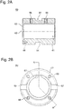
- Fig. 2A is a sectional view of the pump main shaft hub 60.
- Fig. 2B is a plan view of the end surface of the pump main shaft hub 60 that is brought into contact with the pump main shaft 80.
- the pump main shaft hub 60 is a tubular member into which the motor main shaft 22 can be inserted.
- the pump main shaft hub 60 is configured such that the pump main shaft hub 60 is coupled to the motor main shaft 22 via transition fitting when the pump main shaft hub 60 is fitted to the motor main shaft 22.
- the transition fitting means fitting that creates either a gap or a fastening margin between a hole and a shaft when the shaft is fitted into the hole.
- the transition fitting means fitting in a case in which a maximum allowable dimension of the shaft is greater than a minimum allowable dimension of the hole and a minimum allowable dimension of the shaft is smaller than a maximum allowable dimension of the hole.
- the pump main shaft hub 60 has a through-hole 61 into which the motor main shaft 22 is inserted. Also, as illustrated in Fig. 2B , the pump main shaft hub 60 has a key groove 67 in an inner surface thereof. When the pump main shaft hub 60 is fitted to the motor main shaft 22, a key formed in the motor main shaft 22, which is not illustrated, is inserted into the key groove 67 in the pump main shaft hub 60. In this manner, a drive force of the motor main shaft 22 in a rotation direction is delivered to the pump main shaft hub 60.
- an end surface 63 of the pump main shaft hub 60 that abuts on the pump main shaft 80 has holes 66 for securing the stud bolts 70 illustrated in Fig. 1 .
- the holes 66 extend substantially in parallel to the through-hole 61 into which the motor main shaft 22 is inserted.
- the stud bolts 70 secured to the holes 66 are disposed so as to extend substantially in parallel to the pump main shaft 80 and the motor main shaft 22 as illustrated in Fig. 1 .
- four holes 66 are provided at equal intervals in the example illustrated in Fig. 2B , the present invention is not limited thereto, and the number of holes 66 that can be provided is any number which is one or more. Note that in Fig.
- a notch portion 62 is formed in the end surface 63. Although the notch portion 62 extends from an inner peripheral surface to an outer peripheral surface of the pump main shaft hub 60 in the embodiment, the present invention is not limited thereto, and it is only necessary for the notch portion 62 to reach at least the outer peripheral surface.
- a locked portion 64 with a recessed shape is formed in the outer peripheral surface of the pump main shaft hub 60.
- the locked portion 64 is configured such that the locking portion of the pulley removing device is engaged therewith when the pump main shaft hub 60 is pulled out of the motor main shaft 22 as will be described later.
- the locked portion 64 can have any shape with which the locking portion of the pulley removing device can be engaged and may have a recessed shape as illustrated in Fig. 2A , for example, or may have a projecting shape.
- the pump main shaft hub 60 has a hole 65 into which the screw 72 (see Fig.
- Fig. 3A is a side view of the pump main shaft 80.
- Fig. 3B is a plan view of the end surface of the pump main shaft 80 that abuts on the end surface 63 of the pump main shaft hub 60.
- the pump main shaft 80 has a flange portion 81, a large diameter portion 82, a small diameter portion 83, and a bolt attachment portion 84.
- the flange portion 81 has an end surface 88 that abuts on the end surface 63 of the pump main shaft hub 60 illustrated in Figs. 2A and 2B .
- Fig. 1 is a side view of the pump main shaft 80.
- Fig. 3B is a plan view of the end surface of the pump main shaft 80 that abuts on the end surface 63 of the pump main shaft hub 60.
- the pump main shaft 80 has a flange portion 81, a large diameter portion 82, a small diameter portion 83, and a bolt attachment portion 84.
- the end surface 88 has holes 89 through which the stud bolts 70 secured to the pump main shaft hub 60 pass.
- the pump main shaft 80 and the motor main shaft 22 are coupled via the pup main shaft hub 60 by fastening the nuts 71 in a state in which the stud bolts 70 secured to the pump main shaft hub 60 pass through the holes 89 in the flange portion 81 of the pump main shaft 80.
- the large diameter portion 82 is a portion that extends from the flange portion 81 and passes through the pore 44a in the casing cover 44 as illustrated in Fig. 1 .
- the mechanical seal 48 is located at an outer periphery of the large diameter portion 82 and applies sealing between the pore 44a of the casing cover 44 and the large diameter portion 82 of the pump main shaft 80.
- the small diameter portion 83 extends from the large diameter portion 82 and has a smaller outer diameter than the outer diameter of the large diameter portion 82.
- a key groove 85 is formed in an outer peripheral surface of the small diameter portion 83.
- the bolt attachment portion 84 is a portion that extends from the small diameter portion 83 and is located at the furthest end and has a smaller outer diameter than the outer diameter of the small diameter portion 83.
- a screw groove 86 is formed in an outer peripheral surface of the bolt attachment portion 84, and the impeller 46 is prevented from dropping out of the pump main shaft 80 by screwing the blade stopper nut 51 illustrated in Fig. 1 into the screw groove 86 in a state in which the impeller 46 is attached to the small diameter portion 83.
- the pump main shaft hub 60 is coupled to the motor main shaft 22 via transition fitting in the embodiment. Therefore, it is possible to pull the pump main shaft hub 60 out of the motor main shaft 22 using a pulley removing device and to reduce the clearance between the pump main shaft hub 60 and the motor main shaft 22.
- the pump main shaft 80 and the impeller 46 connected to the pump main shaft hub 60 also similarly deviate from the axial center of the motor main shaft, and as a result, there is a concern that the impeller 46 comes into contact with the liner ring 50.
- the inner diameter of the liner ring 50 increases, the clearance between the liner ring 50 and the impeller 46 increases, the amount of a fluid flowing from the clearance to the low-pressure side thus increases, and pump efficiency is degraded.
- the pump main shaft hub 60 is coupled to the motor main shaft 22 via transition fitting, it is possible to reduce the deviation between the axial centers of the pump main shaft hub 60 and the motor main shaft, and as a result, it is possible to prevent the contact between the liner ring 50 and the impeller 46, and it is not necessary to increase the inner diameter of the liner ring 50.
- the pump device 10 according to the embodiment can curb the degradation of pump efficiency as compared with a case in which the pump main shaft hub 60 can easily be pulled out (with a hand, for example) out of the motor main shaft 22.
- the motor 20 and the pump 40 may be disassembled when the motor 20 is replaced, when maintenance for a bearing of the motor 20 is carried out, when maintenance for the pump device 10 is carried out, and the like.
- the pump main shaft 80 is secured to the pump main shaft hub 60 by fastening the nuts 71 to the stud bolts 70 secured to the pump main shaft hub 60. Therefore, it is possible to separate the pump main shaft 80 from the pump main shaft hub 60 by detaching the nuts 71 from the stud bolts 70 when the motor 20 and the pump 40 are disassembled.
- the pump main shaft 80 is secured to the pump main shaft hub 60 with a hexagon bolt instead of the stud bolts 70 and the nuts 71.
- a hexagon bolt instead of the stud bolts 70 and the nuts 71.
- a space that is larger in the axial direction than a pulling margin for detaching the nuts 71 from the stud bolts 70 (the length of exposed portions of the stud bolts 70 and the length of the nuts 71) is required.
- the motor 20 is pulled out of the pump main shaft hub 60 with the pump main shaft 80 and the pump main shaft hub 60 coupled to each other, in order to separate the pump 40 from the motor 20 in the case in which the pump main shaft 80 is secured to the pump main shaft hub 60 with the hexagon bolt.
- a nut 53 coupling the bracket 49 to the motor 20 and the screw 72 are detached, and the motor 20 is pulled out of the pump main shaft hub 60.
- a pulley removing device cannot be used in this case, it is necessary to couple the motor main shaft 22 to the pump main shaft hub 60 with clearance fitting rather than transition fitting, in order to pull the motor 20 out of the pump main shaft hub 60.
- the bracket 49 has the opening 52 for detaching the nuts 71 from the stud bolts 70. Specifically, it is possible to insert a tool into the opening 52 and thereby to detach the nuts 71 without disassembling the bracket 49 from the pump 40 and the motor 20. As a result, it is possible to detach the nuts 71 from the stud bolts 70 and to detach the pump main shaft 80 from the pump main shaft hub 60. Also, since the opening 52 is provided closer to the mechanical seal 48 than to the motor 20 in the axial direction of the pump main shaft 80, the opening 52 can be used as a window for inspecting the mechanical seal 48.
- the pump main shaft hub 60 has, in the outer peripheral surface thereof, the locked portion 64 engaged with the locking portion of the pulley removing device. Therefore, it is possible to pull the pump main shaft hub 60 out of the motor main shaft 22 using the pulley removing device after detaching the pump main shaft 80 from the pump main shaft hub 60.
- the pump main shaft hub 60 has the notch portion 62 extending up to the outer peripheral surface in the end surface 63 that abuts on the flange portion 81 of the pump main shaft 80. In this manner, it is possible to easily separate the pump main shaft 80 from the pump main shaft hub 60 by inserting a tool such as a flathead screwdriver into the notch portion 62 when the pump main shaft 80 is detached from the pump main shaft hub 60.
- the pump main shaft 80 is detached from the pump main shaft hub 60 (first process). Specifically, the protection plate attached to the opening 52 of the bracket 49, which is not illustrated, is detached, and the nuts 71 are detached from the stud bolts 70 through the opening 52. Then, a tool such as a flathead screwdriver is inserted into the notch portion 62 formed in the end surface 63 of the pump main shaft hub 60 to separate the pump main shaft 80 from the pump main shaft hub 60.
- the pump main shaft hub 60 is pulled out of the motor main shaft 22 (second process). Specifically, the nut 53 connecting the bracket 49 to the motor 20 is detached, and the motor 20 is pulled out of the pump 40 along with the pump main shaft hub 60. Thereafter, the screw 72 is detached from the pump main shaft hub 60. Next, the locking portion of the pulley removing device is engaged with the locked portion 64 formed in the outer peripheral surface of the pump main shaft hub 60, and the pump main shaft hub 60 is pulled out of the motor main shaft 22. At this time, the pump main shaft hub 60 is preferably heated with a burner or the like. In this manner, it is possible to easily detach the motor 20 from the pump 40.
- a pump includes: an impeller; a pump main shaft to which the impeller is attached; and a pump main shaft hub that is detachably attached to an end of the pump main shaft, and the pump main shaft hub is a tubular member, into which a motor main shaft is able to be inserted, which is configured to be coupled to the motor main shaft via transition fitting.
- the pump main shaft has a flange portion at the end
- the pump further has a stud bolt and a nut for detachably attaching an end surface of the pump main shaft hub to the flange portion of the pump main shaft
- the end surface of the pump main shaft hub has a hole for securing the stud bolt
- the pump according to the second aspect includes: a casing and a casing cover that accommodate the impeller; and a bracket that couples the casing cover to a motor and internally accommodates the pump main shaft hub, and the bracket has an opening for detaching the nut from the stud bolt.
- the casing cover has a pore through which the pump main shaft passes
- the pump further has a sealing mechanism that applies sealing between the pump main shaft and the casing cover, and the opening is provided closer to the sealing mechanism than to the motor in an axial direction of the pump main shaft.
- the pump main shaft hub has, in an outer peripheral surface, a locked portion that is engaged with a locking portion of a pulley removing device.
- the pump main shaft has a flange portion at the end
- the pump main shaft hub has, in an end surface that abuts on the flange portion of the pump main shaft, a notch portion extending up to the outer peripheral surface.
- a pump device includes: the pump according to any one of the first to sixth aspects; and a motor that has the motor main shaft coupled to the pump main shaft hub of the pump via transition fitting.
- a method for disassembling a pump device in which a pump main shaft and a motor main shaft are connected via a pump main shaft hub fitted to the motor main shaft.
- the method for disassembling a pump device includes: a first process of detaching the pump main shaft from the pump main shaft hub; and a second process of pulling the pump main shaft hub out of the motor main shaft after the first process.
- the first process includes a process of detaching a nut screwed onto a stud bolt attached to the pump main shaft hub.
- the process of detaching the nut includes coupling a casing cover to a motor and detaching the nut through an opening formed in a bracket that internally accommodates the pump main shaft hub.
- the first process includes inserting a tool into a notch portion formed in an end surface of the pump main shaft hub that abuts on a flange portion of the pump main shaft and separating the flange portion of the pump main shaft from the pump main shaft hub.
- the second process includes engaging a locking portion of a pulley removing device with a locked portion formed in an outer peripheral surface of the pump main shaft hub and pulling the pump main shaft hub out of the motor main shaft.
Landscapes
- Engineering & Computer Science (AREA)
- General Engineering & Computer Science (AREA)
- Mechanical Engineering (AREA)
- Structures Of Non-Positive Displacement Pumps (AREA)
Abstract
Description
- The present invention relates to a pump, a pump device, and a method for disassembling a pump device.
- A motor integrated pump in which a motor main shaft is coupled to a pump main shaft is known. In such a motor integrated pump, the main shaft extends up to a position to which an impeller of the pump is attached.
- As a method for coupling the motor main shaft to the pump main shaft, inserting and coupling a distal end of the pump main shaft into a pore of the motor main shaft in a wedge-shaped manner is known (see PTL 1). Also, coupling the motor main shaft to the pump main shaft with a claw coupling with an elastic element interposed therebetween is also known (see PTL 2).
-
- PTL 1: Japanese Utility Model Publication No.
45-11746 - PTL 2: Japanese Utility Model Laid-Open No.
61-116192 - However, with the coupling method described in PTL 1, there is a concern that the pump main shaft cannot be pulled out of the pore of the motor main shaft when the pump is separated from the motor, for example, since the distal end of the pump main shaft is press-fitted into the pore of the motor main shaft in a wedge-shaped manner. Thus, there is a problem that it is difficult to carry out maintenance of the pump. Also, with the coupling method described in PTL 2, manufacturing costs increase since the claw coupling with a complicated shape is used to couple the pump main shaft to the motor main shaft. Also, operability when the pump is separated from the motor is not satisfactory.
- The present invention was made in view of the aforementioned problems, and one of objects thereof is to provide a pump that facilitates separation from a motor while curbing degradation of pump performance.
- According to an aspect of the present invention, a pump is provided. The pump includes: an impeller; a pump main shaft to which the impeller is attached; and a pump main shaft hub that is detachably attached to an end of the pump main shaft. The pump main shaft hub is a tubular member, into which a motor main shaft is able to be inserted, which is configured to be coupled to the motor main shaft via transition fitting.
- According to another aspect of the present invention, there is provided a method for disassembling a pump device in which a pump main shaft and a motor main shaft are connected via a pump main shaft hub fitted to the motor main shaft. The method for disassembling a pump includes: a first process of detaching the pump main shaft from the pump main shaft hub; and a second process of pulling the pump main shaft hub out of the motor main shaft after the first process.
-
- [
Fig. 1] Fig. 1 is a partial side sectional view of a pump device according to an embodiment. - [
Fig. 2A] Fig. 2A is a sectional view of a pump main shaft hub. - [
Fig. 2B] Fig. 2B is a plan view of an end surface of the pump main shaft hub, which is brought into contact with a pump main shaft. - [
Fig. 3A] Fig. 3A is a side view of the pump main shaft. - [
Fig. 3B] Fig. 3B is a plan view of an end surface of the pump main shaft, which abuts on the end surface of the pump main shaft hub. - Hereinafter, an embodiment of the present invention will be described with reference to drawings. The same reference signs will be applied to the same or corresponding components in the drawings described below, and repeated description will be omitted. Note that a transverse-type land pump will be described as an example of the pump device according to the present invention in the embodiment described below.
-
Fig. 1 is a partial side sectional view of a pump device according to an embodiment. InFig. 1 , portions except for a motor are illustrated in the sectional view. As illustrated inFig. 1 , apump device 10 has amotor 20, abase 30, and apump 40. Thepump 40 and themotor 20 are secured onto thebase 30. Themotor 20 has a motormain body 21 and a rotatable motormain shaft 22. A pumpmain shaft hub 60 with a substantially cylindrical shape is fitted to the motormain shaft 22, and the pumpmain shaft hub 60 is pressed against and secured to the motormain shaft 22 in a radial direction with ascrew 72. - The
pump 40 has acasing 41 configured to accommodate animpeller 46 and a pumpmain shaft 80 to which theimpeller 46 is attached. Theimpeller 46 is fitted to the pumpmain shaft 80 and is secured to the pumpmain shaft 80 with ablade stopper nut 51 such that theimpeller 46 does not move in the axial direction. The pumpmain shaft 80 is secured to the pumpmain shaft hub 60 withstud bolts 70 andnuts 71 and is coupled to the motormain shaft 22 via the pumpmain shaft hub 60. Since a drive force of the motormain shaft 22 in a rotation direction is transferred to the pumpmain shaft 80 in this manner, the motormain shaft 22 is configured to be able to rotate along with theimpeller 46. Thepump 40 according to the embodiment is a horizontal-shaft pump and is coupled such that the motormain shaft 22 of themotor 20 and the pumpmain shaft 80 of thepump 40 extend in a substantially horizontal direction. - The
casing 41 has a suctioningpipe 43 for suctioning a liquid and anejection pipe 42 for ejecting a liquid with a pressure boosted by theimpeller 46. Acasing cover 44 is attached to thecasing 41 on the side of themotor 20. Thecasing 41 and thecasing cover 44 define a space accommodating theimpeller 46 and a flow path of the liquid. Thecasing cover 44 has apore 44a through which the pumpmain shaft 80 passes. A mechanical seal 48 (corresponding to an example of the sealing mechanism) that seals a clearance between the pumpmain shaft 80 and thepore 44a of thecasing cover 44 is provided therebetween to curb flowing-out of a liquid from the space in thecasing 41 and thecasing cover 44 through thepore 44a. -
Liner rings 50 are provided at portions of thecasing 41 and thecasing cover 44 that face theimpeller 46. The liner rings 50 form minute clearances with theimpeller 46 therebetween, curb returning of the liquid with a pressure boosted by theimpeller 46 to a low-pressure side, and improve pump efficiency. - The
pump device 10 has abracket 49 that connects thecasing cover 44 to themotor 20. Thebracket 49 internally accommodates a coupling portion between the pumpmain shaft 80 and the motormain shaft 22. In other words, thebracket 49 is configured to internally accommodate the pumpmain shaft hub 60. Thebracket 49 has an opening 52 for detaching thenuts 71 from thestud bolts 70. Theopening 52 is provided at a position at which an operator can visually recognize themechanical seal 48. Specifically, theopening 52 is preferably provided closer to themechanical seal 48 than to themotor 20 in an axial direction of the pumpmain shaft 80, for example. In other words, theopening 52 is preferably provided on the side of themechanical seal 48 beyond the center of the bracket in the axial direction. In this manner, the operator can easily look into themechanical seal 48 from theopening 52 for inspection of themechanical seal 48. Note that a protection plate, which is not illustrated, is attached to theopening 52 during an operation of thepump device 10. - Next, details of the pump
main shaft hub 60 will be described.Fig. 2A is a sectional view of the pumpmain shaft hub 60. Also,Fig. 2B is a plan view of the end surface of the pumpmain shaft hub 60 that is brought into contact with the pumpmain shaft 80. As illustrated inFig. 2A , the pumpmain shaft hub 60 is a tubular member into which the motormain shaft 22 can be inserted. Here, the pumpmain shaft hub 60 is configured such that the pumpmain shaft hub 60 is coupled to the motormain shaft 22 via transition fitting when the pumpmain shaft hub 60 is fitted to the motormain shaft 22. Here, the transition fitting means fitting that creates either a gap or a fastening margin between a hole and a shaft when the shaft is fitted into the hole. In other words, the transition fitting means fitting in a case in which a maximum allowable dimension of the shaft is greater than a minimum allowable dimension of the hole and a minimum allowable dimension of the shaft is smaller than a maximum allowable dimension of the hole. When the pumpmain shaft hub 60 is fitted to the motormain shaft 22, shrinkage fitting, for example, is performed. Also, since the pumpmain shaft hub 60 is fitted to the motormain shaft 22 via the transition fitting, it is possible to pull the pumpmain shaft hub 60 out of the motormain shaft 22 using a pulley removing device (gear puller). Thus, it is possible to reduce the clearance between the pumpmain shaft hub 60 and the motormain shaft 22 within a range in which it is possible to pull the pumpmain shaft hub 60 out of the motormain shaft 22 if the pulley removing device is used in the embodiment. - As illustrated in
Fig. 2A , the pumpmain shaft hub 60 has a through-hole 61 into which the motormain shaft 22 is inserted. Also, as illustrated inFig. 2B , the pumpmain shaft hub 60 has akey groove 67 in an inner surface thereof. When the pumpmain shaft hub 60 is fitted to the motormain shaft 22, a key formed in the motormain shaft 22, which is not illustrated, is inserted into thekey groove 67 in the pumpmain shaft hub 60. In this manner, a drive force of the motormain shaft 22 in a rotation direction is delivered to the pumpmain shaft hub 60. - As illustrated in
Figs. 2A and 2B , anend surface 63 of the pumpmain shaft hub 60 that abuts on the pumpmain shaft 80 hasholes 66 for securing thestud bolts 70 illustrated inFig. 1 . Theholes 66 extend substantially in parallel to the through-hole 61 into which the motormain shaft 22 is inserted. Thus, thestud bolts 70 secured to theholes 66 are disposed so as to extend substantially in parallel to the pumpmain shaft 80 and the motormain shaft 22 as illustrated inFig. 1 . Although fourholes 66 are provided at equal intervals in the example illustrated inFig. 2B , the present invention is not limited thereto, and the number ofholes 66 that can be provided is any number which is one or more. Note that inFig. 2A , only onehole 66 is illustrated while theother holes 66 are omitted. Anotch portion 62 is formed in theend surface 63. Although thenotch portion 62 extends from an inner peripheral surface to an outer peripheral surface of the pumpmain shaft hub 60 in the embodiment, the present invention is not limited thereto, and it is only necessary for thenotch portion 62 to reach at least the outer peripheral surface. - As illustrated in
Fig. 2A , a lockedportion 64 with a recessed shape is formed in the outer peripheral surface of the pumpmain shaft hub 60. The lockedportion 64 is configured such that the locking portion of the pulley removing device is engaged therewith when the pumpmain shaft hub 60 is pulled out of the motormain shaft 22 as will be described later. The lockedportion 64 can have any shape with which the locking portion of the pulley removing device can be engaged and may have a recessed shape as illustrated inFig. 2A , for example, or may have a projecting shape. Also,the pumpmain shaft hub 60 has ahole 65 into which the screw 72 (seeFig. 1 ) for pressing the pumpmain shaft hub 60 against the motormain shaft 22 and securing the pumpmain shaft hub 60 to the motormain shaft 22 in the radial direction is screwed. Although twoholes 65 are provided at separate locations in the axial direction in the example illustrated inFig. 2A , it is possible to provide any number ofholes 65. - Next, details of the pump
main shaft 80 illustrated inFig. 1 will be described.Fig. 3A is a side view of the pumpmain shaft 80.Fig. 3B is a plan view of the end surface of the pumpmain shaft 80 that abuts on theend surface 63 of the pumpmain shaft hub 60. As illustrated inFig. 3A , the pumpmain shaft 80 has aflange portion 81, alarge diameter portion 82, asmall diameter portion 83, and abolt attachment portion 84. Theflange portion 81 has anend surface 88 that abuts on theend surface 63 of the pumpmain shaft hub 60 illustrated inFigs. 2A and 2B . As illustrated inFig. 3B , theend surface 88 hasholes 89 through which thestud bolts 70 secured to the pumpmain shaft hub 60 pass. In the illustrated example, fourholes 89 corresponding to the number ofholes 66 in the pumpmain shaft hub 60 to which thestud bolts 70 are secured, that is, the number ofstud bolts 70 are provided in theend surface 88 of the pumpmain shaft 80. As illustrated inFig. 1 , the pumpmain shaft 80 and the motormain shaft 22 are coupled via the pupmain shaft hub 60 by fastening the nuts 71 in a state in which thestud bolts 70 secured to the pumpmain shaft hub 60 pass through theholes 89 in theflange portion 81 of the pumpmain shaft 80. - The
large diameter portion 82 is a portion that extends from theflange portion 81 and passes through thepore 44a in thecasing cover 44 as illustrated inFig. 1 . As illustrated inFig. 1 , themechanical seal 48 is located at an outer periphery of thelarge diameter portion 82 and applies sealing between thepore 44a of thecasing cover 44 and thelarge diameter portion 82 of the pumpmain shaft 80. - The
small diameter portion 83 extends from thelarge diameter portion 82 and has a smaller outer diameter than the outer diameter of thelarge diameter portion 82. Akey groove 85 is formed in an outer peripheral surface of thesmall diameter portion 83. When theimpeller 46 is attached to the pumpmain shaft 80 as illustrated inFig. 1 , one key, which is not illustrated, is inserted into a key groove formed in the inner peripheral surface of theimpeller 46, which is not illustrated, and thekey groove 85 of the pumpmain shaft 80. In this manner, a drive force of the pumpmain shaft 80 in the rotation direction is delivered to theimpeller 46. - The
bolt attachment portion 84 is a portion that extends from thesmall diameter portion 83 and is located at the furthest end and has a smaller outer diameter than the outer diameter of thesmall diameter portion 83. Ascrew groove 86 is formed in an outer peripheral surface of thebolt attachment portion 84, and theimpeller 46 is prevented from dropping out of the pumpmain shaft 80 by screwing theblade stopper nut 51 illustrated inFig. 1 into thescrew groove 86 in a state in which theimpeller 46 is attached to thesmall diameter portion 83. - Effects and advantages of the
pump device 10 according to the embodiment described above will be described in detail. As described above, the pumpmain shaft hub 60 is coupled to the motormain shaft 22 via transition fitting in the embodiment. Therefore, it is possible to pull the pumpmain shaft hub 60 out of the motormain shaft 22 using a pulley removing device and to reduce the clearance between the pumpmain shaft hub 60 and the motormain shaft 22. On the other hand, in a case in which a clearance is formed between the pumpmain shaft hub 60 and the motormain shaft 22 to such an extent that the pumpmain shaft hub 60 can be pulled easily (with a hand, for example) out of the motormain shaft 22, specifically, in a case in which the pumpmain shaft hub 60 and the motormain shaft 22 are connected via clearance fitting, for example, an axial center of the pumpmain shaft hub 60 deviates from the axial center of the motormain shaft 22 by the amount corresponding to the aforementioned clearance due the pumpmain shaft hub 60 secured to the motormain shaft 22 with thescrew 72. In this case, the pumpmain shaft 80 and theimpeller 46 connected to the pumpmain shaft hub 60 also similarly deviate from the axial center of the motor main shaft, and as a result, there is a concern that theimpeller 46 comes into contact with theliner ring 50. In order to avoid the contact between theimpeller 46 and theliner ring 50, it is necessary to further increase the inner diameter of theliner ring 50. However, if the inner diameter of theliner ring 50 increases, the clearance between theliner ring 50 and theimpeller 46 increases, the amount of a fluid flowing from the clearance to the low-pressure side thus increases, and pump efficiency is degraded. In the embodiment, since the pumpmain shaft hub 60 is coupled to the motormain shaft 22 via transition fitting, it is possible to reduce the deviation between the axial centers of the pumpmain shaft hub 60 and the motor main shaft, and as a result, it is possible to prevent the contact between theliner ring 50 and theimpeller 46, and it is not necessary to increase the inner diameter of theliner ring 50. Thus, thepump device 10 according to the embodiment can curb the degradation of pump efficiency as compared with a case in which the pumpmain shaft hub 60 can easily be pulled out (with a hand, for example) out of the motormain shaft 22. - In the
pump device 10, themotor 20 and thepump 40 may be disassembled when themotor 20 is replaced, when maintenance for a bearing of themotor 20 is carried out, when maintenance for thepump device 10 is carried out, and the like. In the embodiment, the pumpmain shaft 80 is secured to the pumpmain shaft hub 60 by fastening the nuts 71 to thestud bolts 70 secured to the pumpmain shaft hub 60. Therefore, it is possible to separate the pumpmain shaft 80 from the pumpmain shaft hub 60 by detaching the nuts 71 from thestud bolts 70 when themotor 20 and thepump 40 are disassembled. - On the other hand, it is also conceivable that the pump
main shaft 80 is secured to the pumpmain shaft hub 60 with a hexagon bolt instead of thestud bolts 70 and the nuts 71. However, in this case, it is necessary to form a space corresponding to a pulling margin of the hexagon bolt (the length corresponding to the entire length of the hexagon bolt) between theflange portion 81 of the pumpmain shaft 80 and thecasing cover 44 in order to separate the pumpmain shaft 80 from the pump main shaft hub 60 (seeFig. 1 ). In this case, a space that is larger in the axial direction than a pulling margin for detaching the nuts 71 from the stud bolts 70 (the length of exposed portions of thestud bolts 70 and the length of the nuts 71) is required. Thus, since it is necessary to increase the length of the pumpmain shaft 80, an overhang of thepump device 10 is elongated, and the amount of deflection of the pumpmain shaft 80 increases. As a result, swinging of the pumpmain shaft 80 increases. Also, since it is also necessary to increase the length of thebracket 49 in the axial direction with the increase in length of the pumpmain shaft 80, this leads to an increase in weight and costs of thepump device 10. On the other hand, thestud bolts 70 and the nuts 71 are used in the embodiment, and it is thus possible to reduce the lengths of the overhang of thepump device 10 and thebracket 49 in the axial direction as compared with the case in which the hexagon bolt is used. - Also, it is also conceivable that the
motor 20 is pulled out of the pumpmain shaft hub 60 with the pumpmain shaft 80 and the pumpmain shaft hub 60 coupled to each other, in order to separate thepump 40 from themotor 20 in the case in which the pumpmain shaft 80 is secured to the pumpmain shaft hub 60 with the hexagon bolt. Specifically, inFig. 1 , anut 53 coupling thebracket 49 to themotor 20 and thescrew 72 are detached, and themotor 20 is pulled out of the pumpmain shaft hub 60. However, since a pulley removing device cannot be used in this case, it is necessary to couple the motormain shaft 22 to the pumpmain shaft hub 60 with clearance fitting rather than transition fitting, in order to pull themotor 20 out of the pumpmain shaft hub 60. Thus, since the clearance between the motormain shaft 22 and the pumpmain shaft hub 60 increases as described above, deviation between the axial centers of the motormain shaft 22 and the pumpmain shaft 80 increases when the pumpmain shaft hub 60 is secured to the motormain shaft 22 with thescrew 72. On the other hand, since thestud bolts 70 and the nuts 71 are used in the embodiment, it is possible to disassemble thepump 40 and themotor 20 by separating the pumpmain shaft 80 from the pumpmain shaft hub 60. As a result, it is possible to pull the pumpmain shaft hub 60 out of the motormain shaft 22 using a pulley removing device after separating the pumpmain shaft 80 from the pumpmain shaft hub 60 even if the pumpmain shaft hub 60 is transition-fitted to the pumpmain shaft 80. - In the embodiment, the
bracket 49 has theopening 52 for detaching the nuts 71 from thestud bolts 70. Specifically, it is possible to insert a tool into theopening 52 and thereby to detach thenuts 71 without disassembling thebracket 49 from thepump 40 and themotor 20. As a result, it is possible to detach the nuts 71 from thestud bolts 70 and to detach the pumpmain shaft 80 from the pumpmain shaft hub 60. Also, since theopening 52 is provided closer to themechanical seal 48 than to themotor 20 in the axial direction of the pumpmain shaft 80, theopening 52 can be used as a window for inspecting themechanical seal 48. - The pump
main shaft hub 60 according to the embodiment has, in the outer peripheral surface thereof, the lockedportion 64 engaged with the locking portion of the pulley removing device. Therefore, it is possible to pull the pumpmain shaft hub 60 out of the motormain shaft 22 using the pulley removing device after detaching the pumpmain shaft 80 from the pumpmain shaft hub 60. - Further, the pump
main shaft hub 60 according to the embodiment has thenotch portion 62 extending up to the outer peripheral surface in theend surface 63 that abuts on theflange portion 81 of the pumpmain shaft 80. In this manner, it is possible to easily separate the pumpmain shaft 80 from the pumpmain shaft hub 60 by inserting a tool such as a flathead screwdriver into thenotch portion 62 when the pumpmain shaft 80 is detached from the pumpmain shaft hub 60. - Next, a method for disassembling the pump device according to the embodiment will be described. First, securing the
motor 20 and thepump 40 to thebase 30 is released. Next, the pumpmain shaft 80 is detached from the pump main shaft hub 60 (first process). Specifically, the protection plate attached to theopening 52 of thebracket 49, which is not illustrated, is detached, and the nuts 71 are detached from thestud bolts 70 through theopening 52. Then, a tool such as a flathead screwdriver is inserted into thenotch portion 62 formed in theend surface 63 of the pumpmain shaft hub 60 to separate the pumpmain shaft 80 from the pumpmain shaft hub 60. - Next, the pump
main shaft hub 60 is pulled out of the motor main shaft 22 (second process). Specifically, thenut 53 connecting thebracket 49 to themotor 20 is detached, and themotor 20 is pulled out of thepump 40 along with the pumpmain shaft hub 60. Thereafter, thescrew 72 is detached from the pumpmain shaft hub 60. Next, the locking portion of the pulley removing device is engaged with the lockedportion 64 formed in the outer peripheral surface of the pumpmain shaft hub 60, and the pumpmain shaft hub 60 is pulled out of the motormain shaft 22. At this time, the pumpmain shaft hub 60 is preferably heated with a burner or the like. In this manner, it is possible to easily detach themotor 20 from thepump 40. - Although the embodiment of the present invention has been described above, the aforementioned embodiment of the present invention is intended to facilitate understanding of the present invention and is not intended to limit the present invention. It is a matter of course that the present invention can be modified and improved without departing from the gist thereof and includes the equivalents. Also, it is possible to optionally combine or omit components described in the claims and the specification within a range in which at least some of the aforementioned problems can be solved or within a range in which at least some of the advantages can be achieved.
- Hereinafter, some of the aspects that the specification discloses will be described below.
- According to a first aspect, a pump is provided. The pump includes: an impeller; a pump main shaft to which the impeller is attached; and a pump main shaft hub that is detachably attached to an end of the pump main shaft, and the pump main shaft hub is a tubular member, into which a motor main shaft is able to be inserted, which is configured to be coupled to the motor main shaft via transition fitting.
- According to a second aspect, in the pump according to the first aspect, the pump main shaft has a flange portion at the end, the pump further has a stud bolt and a nut for detachably attaching an end surface of the pump main shaft hub to the flange portion of the pump main shaft, and the end surface of the pump main shaft hub has a hole for securing the stud bolt.
- According to a third aspect, the pump according to the second aspect includes: a casing and a casing cover that accommodate the impeller; and a bracket that couples the casing cover to a motor and internally accommodates the pump main shaft hub, and the bracket has an opening for detaching the nut from the stud bolt.
- According to a fourth aspect, in the pump according to the third aspect, the casing cover has a pore through which the pump main shaft passes, the pump further has a sealing mechanism that applies sealing between the pump main shaft and the casing cover, and the opening is provided closer to the sealing mechanism than to the motor in an axial direction of the pump main shaft.
- According to a fifth aspect, in the pump according to any one of the first to fourth aspects, the pump main shaft hub has, in an outer peripheral surface, a locked portion that is engaged with a locking portion of a pulley removing device.
- According to a sixth aspect, in the pump according to any one of the first to fifth aspects, the pump main shaft has a flange portion at the end, and the pump main shaft hub has, in an end surface that abuts on the flange portion of the pump main shaft, a notch portion extending up to the outer peripheral surface.
- According to a seventh aspect, a pump device is provided. The pump device includes: the pump according to any one of the first to sixth aspects; and a motor that has the motor main shaft coupled to the pump main shaft hub of the pump via transition fitting.
- According to an eighth aspect, there is provided a method for disassembling a pump device in which a pump main shaft and a motor main shaft are connected via a pump main shaft hub fitted to the motor main shaft. The method for disassembling a pump device includes: a first process of detaching the pump main shaft from the pump main shaft hub; and a second process of pulling the pump main shaft hub out of the motor main shaft after the first process.
- According to a ninth aspect, in the method for disassembling a pump device according to the eighth aspect, the first process includes a process of detaching a nut screwed onto a stud bolt attached to the pump main shaft hub.
- According to a tenth aspect, in the method for disassembling a pump device according to the ninth aspect, the process of detaching the nut includes coupling a casing cover to a motor and detaching the nut through an opening formed in a bracket that internally accommodates the pump main shaft hub.
- According to an eleventh aspect, in the method for disassembling a pump device according to any one of the eighth to tenth aspects, the first process includes inserting a tool into a notch portion formed in an end surface of the pump main shaft hub that abuts on a flange portion of the pump main shaft and separating the flange portion of the pump main shaft from the pump main shaft hub.
- According to a twelfth aspect, in the method for disassembling a pump device according to any one of the eighth to eleventh aspects, the second process includes engaging a locking portion of a pulley removing device with a locked portion formed in an outer peripheral surface of the pump main shaft hub and pulling the pump main shaft hub out of the motor main shaft.
-
- 10
- Pump device
- 20
- Motor
- 22
- Motor main shaft
- 40
- Pump
- 41
- Casing
- 44
- Casing cover
- 44a
- Pore
- 46
- Impeller
- 48
- Mechanical seal
- 49
- Bracket
- 52
- Opening
- 60
- Pump main shaft hub
- 62
- Notch portion
- 63
- End surface
- 64
- Locked portion
- 66
- Hole
- 70
- Stud bolt
- 71
- Nut
- 80
- Pump main shaft
- 81
- Flange portion
- 88
- End surface
Claims (12)
- A pump comprising:an impeller;a pump main shaft to which the impeller is attached; anda pump main shaft hub that is detachably attached to an end of the pump main shaft,wherein the pump main shaft hub is a tubular member, into which a motor main shaft is able to be inserted, which is configured to be coupled to the motor main shaft via transition fitting.
- The pump according to claim 1,
wherein the pump main shaft has a flange portion at the end,
the pump further comprises a stud bolt and a nut for detachably attaching an end surface of the pump main shaft hub to the flange portion of the pump main shaft, and
the end surface of the pump main shaft hub has a hole for securing the stud bolt. - The pump according to claim 2, comprising:a casing and a casing cover that accommodate the impeller; anda bracket that couples the casing cover to a motor and internally accommodates the pump main shaft hub,wherein the bracket has an opening for detaching the nut from the stud bolt.
- The pump according to claim 3,
wherein the casing cover has a pore through which the pump main shaft passes,
the pump further has a sealing mechanism that applies sealing between the pump main shaft and the casing cover, and
the opening is provided closer to the sealing mechanism than to the motor in an axial direction of the pump main shaft. - The pump according to any one of claims 1 to 4,
wherein the pump main shaft hub has, in an outer peripheral surface, a locked portion that is engaged with a locking portion of a pulley removing device. - The pump according to any one of claims 1 to 5,
wherein the pump main shaft has a flange portion at the end, and
the pump main shaft hub has, in an end surface that abuts on the flange portion of the pump main shaft, a notch portion extending up to the outer peripheral surface. - A pump device comprising:the pump according to any one of claims 1 to 6; anda motor that has the motor main shaft coupled to the pump main shaft hub of the pump via transition fitting.
- A method for disassembling a pump device in which a pump main shaft and a motor main shaft are connected via a pump main shaft hub fitted to the motor main shaft, the method comprising:a first process of detaching the pump main shaft from the pump main shaft hub; anda second process of pulling the pump main shaft hub out of the motor main shaft after the first process.
- The method for disassembling a pump device according to claim 8,
wherein the first process includes a process of detaching a nut screwed onto a stud bolt attached to the pump main shaft hub. - The method for disassembling a pump device according to claim 9,
wherein the process of detaching the nut includes coupling a casing cover to a motor and detaching the nut through an opening formed in a bracket that internally accommodates the pump main shaft hub. - The method for disassembling a pump device according to any one of clams 8 to 10,
wherein the first process includes inserting a tool into a notch portion formed in an end surface of the pump main shaft hub that abuts on a flange portion of the pump main shaft and separating the flange portion of the pump main shaft from the pump main shaft hub. - The method for disassembling a pump device according to any one of claims 8 to 11,
wherein the second process includes engaging a locking portion of a pulley removing device with a locked portion formed in an outer peripheral surface of the pump main shaft hub and pulling the pump main shaft hub out of the motor main shaft.
Applications Claiming Priority (2)
| Application Number | Priority Date | Filing Date | Title |
|---|---|---|---|
| JP2017203632A JP6949657B2 (en) | 2017-10-20 | 2017-10-20 | Pumps, pumping equipment, and how to disassemble the pumping equipment |
| PCT/JP2018/038912 WO2019078316A1 (en) | 2017-10-20 | 2018-10-19 | Pump, pump device, and method of disassembling pump device |
Publications (3)
| Publication Number | Publication Date |
|---|---|
| EP3699435A1 true EP3699435A1 (en) | 2020-08-26 |
| EP3699435A4 EP3699435A4 (en) | 2021-07-14 |
| EP3699435B1 EP3699435B1 (en) | 2023-09-13 |
Family
ID=66173740
Family Applications (1)
| Application Number | Title | Priority Date | Filing Date |
|---|---|---|---|
| EP18868678.6A Active EP3699435B1 (en) | 2017-10-20 | 2018-10-19 | Pump, pump device, and method of disassembling pump device |
Country Status (6)
| Country | Link |
|---|---|
| EP (1) | EP3699435B1 (en) |
| JP (1) | JP6949657B2 (en) |
| CN (1) | CN111226043A (en) |
| AU (1) | AU2018353673B2 (en) |
| ES (1) | ES2963338T3 (en) |
| WO (1) | WO2019078316A1 (en) |
Families Citing this family (1)
| Publication number | Priority date | Publication date | Assignee | Title |
|---|---|---|---|---|
| DE202019105336U1 (en) * | 2019-09-26 | 2021-01-05 | Evoguard Gmbh | Pump shaft with fastening bolts |
Family Cites Families (15)
| Publication number | Priority date | Publication date | Assignee | Title |
|---|---|---|---|---|
| JPS4511746Y1 (en) | 1966-10-26 | 1970-05-25 | ||
| JPS518600U (en) * | 1974-07-08 | 1976-01-22 | ||
| JPS61116192U (en) | 1984-12-29 | 1986-07-22 | ||
| JPH02243230A (en) * | 1989-03-13 | 1990-09-27 | Toshiba Eng & Constr Co Ltd | Removing device for pulley of rotating machine |
| US5051071A (en) * | 1990-02-09 | 1991-09-24 | Haentjens Walter D | Heat dissipating coupling for rotary shafts |
| JPH0942193A (en) * | 1995-07-27 | 1997-02-10 | Hitachi Ltd | Rotary pump and rotary impeller fixing method |
| JP4131597B2 (en) * | 1999-05-24 | 2008-08-13 | 三菱重工業株式会社 | Extractor |
| CN2451786Y (en) * | 2000-11-28 | 2001-10-03 | 何良贵 | Unit construction centrifugal pump with easy-to-disassemble axil |
| CN201149041Y (en) * | 2008-01-25 | 2008-11-12 | 长沙天鹅工业泵股份有限公司 | Sleeve coupling and disassembling tool thereof |
| WO2016053333A1 (en) * | 2014-10-01 | 2016-04-07 | Ge Oil & Gas Esp, Inc. | Shrink disk connection for surface pump thrust carrying shafts |
| CN105508283A (en) * | 2014-10-09 | 2016-04-20 | 株式会社荏原制作所 | A turbopump |
| CN205047448U (en) * | 2015-09-24 | 2016-02-24 | 山东壮发泵业有限公司 | No bearing pump |
| JP6590622B2 (en) * | 2015-10-01 | 2019-10-16 | 株式会社荏原製作所 | Turbo pump |
| CN106762834A (en) * | 2015-11-25 | 2017-05-31 | 天津市明奥泵业有限公司 | The horizontal pipeline pump of novel belt reinforcing plate |
| US10280931B2 (en) * | 2016-01-27 | 2019-05-07 | Pentair Flow Technologies, Llc | Systems and methods for split coupled pump and jacking gland |
-
2017
- 2017-10-20 JP JP2017203632A patent/JP6949657B2/en active Active
-
2018
- 2018-10-19 ES ES18868678T patent/ES2963338T3/en active Active
- 2018-10-19 WO PCT/JP2018/038912 patent/WO2019078316A1/en not_active Ceased
- 2018-10-19 CN CN201880067940.9A patent/CN111226043A/en active Pending
- 2018-10-19 AU AU2018353673A patent/AU2018353673B2/en active Active
- 2018-10-19 EP EP18868678.6A patent/EP3699435B1/en active Active
Also Published As
| Publication number | Publication date |
|---|---|
| JP6949657B2 (en) | 2021-10-13 |
| CN111226043A (en) | 2020-06-02 |
| JP2019078187A (en) | 2019-05-23 |
| AU2018353673B2 (en) | 2024-05-23 |
| ES2963338T3 (en) | 2024-03-26 |
| AU2018353673A1 (en) | 2020-05-28 |
| EP3699435A4 (en) | 2021-07-14 |
| EP3699435B1 (en) | 2023-09-13 |
| WO2019078316A1 (en) | 2019-04-25 |
Similar Documents
| Publication | Publication Date | Title |
|---|---|---|
| CA2891050C (en) | Eccentric screw pump | |
| US8186031B2 (en) | Bushing replacement kit | |
| US12560223B2 (en) | System and method for a captive sprocket in an engine | |
| CN103827507B (en) | Linkage mechanism and there is the variable quiet wing drive unit of this linkage mechanism | |
| CN106994660A (en) | Replacing instrument for driving yoke bushing | |
| EP3006741A1 (en) | Turbopump with shaft coupling | |
| CN112236261A (en) | Method and tool for repairing damaged threads | |
| CN201291372Y (en) | Hydraulic disassembly and assembly of tapered hole bearing device | |
| AU2018353673B2 (en) | Pump, pump device, and method of disassembling pump device | |
| HK1222216A1 (en) | Turbopump | |
| WO2017086345A1 (en) | Shaft coupling and pump device | |
| WO2016053333A1 (en) | Shrink disk connection for surface pump thrust carrying shafts | |
| US20060035746A1 (en) | Drive shaft assembly and method of separation | |
| WO2007043143A1 (en) | Liquid pressure device | |
| CN116733741A (en) | Single-shaft eccentric screw pump | |
| CN108138782B (en) | Pitot tube stabilizing device | |
| JP2021169776A (en) | Pump device and method for assembling pump device | |
| CN101258331B (en) | Eccentric pump with clean-out assembly | |
| US10145475B2 (en) | Mechanical seal device | |
| CN116733740A (en) | Single-shaft eccentric screw pump | |
| JP7105664B2 (en) | rotary fluid machine | |
| JP2021169777A (en) | Pump device and method for disassembling pump device | |
| WO2016076856A1 (en) | Threaded combustor housing with union nut | |
| CN102644741A (en) | A locking mechanism for stirring and sealing and its disassembly method | |
| CN102671575A (en) | A locking device for stirring and sealing and its disassembling method |
Legal Events
| Date | Code | Title | Description |
|---|---|---|---|
| STAA | Information on the status of an ep patent application or granted ep patent |
Free format text: STATUS: THE INTERNATIONAL PUBLICATION HAS BEEN MADE |
|
| PUAI | Public reference made under article 153(3) epc to a published international application that has entered the european phase |
Free format text: ORIGINAL CODE: 0009012 |
|
| STAA | Information on the status of an ep patent application or granted ep patent |
Free format text: STATUS: REQUEST FOR EXAMINATION WAS MADE |
|
| 17P | Request for examination filed |
Effective date: 20200508 |
|
| AK | Designated contracting states |
Kind code of ref document: A1 Designated state(s): AL AT BE BG CH CY CZ DE DK EE ES FI FR GB GR HR HU IE IS IT LI LT LU LV MC MK MT NL NO PL PT RO RS SE SI SK SM TR |
|
| AX | Request for extension of the european patent |
Extension state: BA ME |
|
| DAV | Request for validation of the european patent (deleted) | ||
| DAX | Request for extension of the european patent (deleted) | ||
| REG | Reference to a national code |
Ref country code: DE Free format text: PREVIOUS MAIN CLASS: F04D0029044000 Ref country code: DE Ref legal event code: R079 Ref document number: 602018057682 Country of ref document: DE Free format text: PREVIOUS MAIN CLASS: F04D0029044000 Ipc: F04D0013020000 |
|
| A4 | Supplementary search report drawn up and despatched |
Effective date: 20210611 |
|
| RIC1 | Information provided on ipc code assigned before grant |
Ipc: F04D 13/02 20060101AFI20210607BHEP Ipc: F04D 29/62 20060101ALI20210607BHEP Ipc: F04D 13/06 20060101ALI20210607BHEP Ipc: F16D 1/076 20060101ALI20210607BHEP |
|
| GRAP | Despatch of communication of intention to grant a patent |
Free format text: ORIGINAL CODE: EPIDOSNIGR1 |
|
| STAA | Information on the status of an ep patent application or granted ep patent |
Free format text: STATUS: GRANT OF PATENT IS INTENDED |
|
| INTG | Intention to grant announced |
Effective date: 20230330 |
|
| GRAS | Grant fee paid |
Free format text: ORIGINAL CODE: EPIDOSNIGR3 |
|
| RAP3 | Party data changed (applicant data changed or rights of an application transferred) |
Owner name: EBARA CORPORATION |
|
| GRAA | (expected) grant |
Free format text: ORIGINAL CODE: 0009210 |
|
| STAA | Information on the status of an ep patent application or granted ep patent |
Free format text: STATUS: THE PATENT HAS BEEN GRANTED |
|
| AK | Designated contracting states |
Kind code of ref document: B1 Designated state(s): AL AT BE BG CH CY CZ DE DK EE ES FI FR GB GR HR HU IE IS IT LI LT LU LV MC MK MT NL NO PL PT RO RS SE SI SK SM TR |
|
| P01 | Opt-out of the competence of the unified patent court (upc) registered |
Effective date: 20230807 |
|
| REG | Reference to a national code |
Ref country code: CH Ref legal event code: EP |
|
| REG | Reference to a national code |
Ref country code: DE Ref legal event code: R096 Ref document number: 602018057682 Country of ref document: DE |
|
| REG | Reference to a national code |
Ref country code: IE Ref legal event code: FG4D |
|
| REG | Reference to a national code |
Ref country code: LT Ref legal event code: MG9D |
|
| REG | Reference to a national code |
Ref country code: NL Ref legal event code: MP Effective date: 20230913 |
|
| PG25 | Lapsed in a contracting state [announced via postgrant information from national office to epo] |
Ref country code: GR Free format text: LAPSE BECAUSE OF FAILURE TO SUBMIT A TRANSLATION OF THE DESCRIPTION OR TO PAY THE FEE WITHIN THE PRESCRIBED TIME-LIMIT Effective date: 20231214 |
|
| PG25 | Lapsed in a contracting state [announced via postgrant information from national office to epo] |
Ref country code: SE Free format text: LAPSE BECAUSE OF FAILURE TO SUBMIT A TRANSLATION OF THE DESCRIPTION OR TO PAY THE FEE WITHIN THE PRESCRIBED TIME-LIMIT Effective date: 20230913 Ref country code: RS Free format text: LAPSE BECAUSE OF FAILURE TO SUBMIT A TRANSLATION OF THE DESCRIPTION OR TO PAY THE FEE WITHIN THE PRESCRIBED TIME-LIMIT Effective date: 20230913 Ref country code: NO Free format text: LAPSE BECAUSE OF FAILURE TO SUBMIT A TRANSLATION OF THE DESCRIPTION OR TO PAY THE FEE WITHIN THE PRESCRIBED TIME-LIMIT Effective date: 20231213 Ref country code: LV Free format text: LAPSE BECAUSE OF FAILURE TO SUBMIT A TRANSLATION OF THE DESCRIPTION OR TO PAY THE FEE WITHIN THE PRESCRIBED TIME-LIMIT Effective date: 20230913 Ref country code: LT Free format text: LAPSE BECAUSE OF FAILURE TO SUBMIT A TRANSLATION OF THE DESCRIPTION OR TO PAY THE FEE WITHIN THE PRESCRIBED TIME-LIMIT Effective date: 20230913 Ref country code: HR Free format text: LAPSE BECAUSE OF FAILURE TO SUBMIT A TRANSLATION OF THE DESCRIPTION OR TO PAY THE FEE WITHIN THE PRESCRIBED TIME-LIMIT Effective date: 20230913 Ref country code: GR Free format text: LAPSE BECAUSE OF FAILURE TO SUBMIT A TRANSLATION OF THE DESCRIPTION OR TO PAY THE FEE WITHIN THE PRESCRIBED TIME-LIMIT Effective date: 20231214 Ref country code: FI Free format text: LAPSE BECAUSE OF FAILURE TO SUBMIT A TRANSLATION OF THE DESCRIPTION OR TO PAY THE FEE WITHIN THE PRESCRIBED TIME-LIMIT Effective date: 20230913 |
|
| REG | Reference to a national code |
Ref country code: AT Ref legal event code: MK05 Ref document number: 1611554 Country of ref document: AT Kind code of ref document: T Effective date: 20230913 |
|
| PG25 | Lapsed in a contracting state [announced via postgrant information from national office to epo] |
Ref country code: NL Free format text: LAPSE BECAUSE OF FAILURE TO SUBMIT A TRANSLATION OF THE DESCRIPTION OR TO PAY THE FEE WITHIN THE PRESCRIBED TIME-LIMIT Effective date: 20230913 |
|
| REG | Reference to a national code |
Ref country code: ES Ref legal event code: FG2A Ref document number: 2963338 Country of ref document: ES Kind code of ref document: T3 Effective date: 20240326 |
|
| PG25 | Lapsed in a contracting state [announced via postgrant information from national office to epo] |
Ref country code: IS Free format text: LAPSE BECAUSE OF FAILURE TO SUBMIT A TRANSLATION OF THE DESCRIPTION OR TO PAY THE FEE WITHIN THE PRESCRIBED TIME-LIMIT Effective date: 20240113 |
|
| PG25 | Lapsed in a contracting state [announced via postgrant information from national office to epo] |
Ref country code: AT Free format text: LAPSE BECAUSE OF FAILURE TO SUBMIT A TRANSLATION OF THE DESCRIPTION OR TO PAY THE FEE WITHIN THE PRESCRIBED TIME-LIMIT Effective date: 20230913 |
|
| PG25 | Lapsed in a contracting state [announced via postgrant information from national office to epo] |
Ref country code: SM Free format text: LAPSE BECAUSE OF FAILURE TO SUBMIT A TRANSLATION OF THE DESCRIPTION OR TO PAY THE FEE WITHIN THE PRESCRIBED TIME-LIMIT Effective date: 20230913 Ref country code: RO Free format text: LAPSE BECAUSE OF FAILURE TO SUBMIT A TRANSLATION OF THE DESCRIPTION OR TO PAY THE FEE WITHIN THE PRESCRIBED TIME-LIMIT Effective date: 20230913 Ref country code: IS Free format text: LAPSE BECAUSE OF FAILURE TO SUBMIT A TRANSLATION OF THE DESCRIPTION OR TO PAY THE FEE WITHIN THE PRESCRIBED TIME-LIMIT Effective date: 20240113 Ref country code: EE Free format text: LAPSE BECAUSE OF FAILURE TO SUBMIT A TRANSLATION OF THE DESCRIPTION OR TO PAY THE FEE WITHIN THE PRESCRIBED TIME-LIMIT Effective date: 20230913 Ref country code: CZ Free format text: LAPSE BECAUSE OF FAILURE TO SUBMIT A TRANSLATION OF THE DESCRIPTION OR TO PAY THE FEE WITHIN THE PRESCRIBED TIME-LIMIT Effective date: 20230913 Ref country code: AT Free format text: LAPSE BECAUSE OF FAILURE TO SUBMIT A TRANSLATION OF THE DESCRIPTION OR TO PAY THE FEE WITHIN THE PRESCRIBED TIME-LIMIT Effective date: 20230913 Ref country code: SK Free format text: LAPSE BECAUSE OF FAILURE TO SUBMIT A TRANSLATION OF THE DESCRIPTION OR TO PAY THE FEE WITHIN THE PRESCRIBED TIME-LIMIT Effective date: 20230913 Ref country code: PT Free format text: LAPSE BECAUSE OF FAILURE TO SUBMIT A TRANSLATION OF THE DESCRIPTION OR TO PAY THE FEE WITHIN THE PRESCRIBED TIME-LIMIT Effective date: 20240115 |
|
| REG | Reference to a national code |
Ref country code: DE Ref legal event code: R119 Ref document number: 602018057682 Country of ref document: DE |
|
| PG25 | Lapsed in a contracting state [announced via postgrant information from national office to epo] |
Ref country code: PL Free format text: LAPSE BECAUSE OF FAILURE TO SUBMIT A TRANSLATION OF THE DESCRIPTION OR TO PAY THE FEE WITHIN THE PRESCRIBED TIME-LIMIT Effective date: 20230913 |
|
| REG | Reference to a national code |
Ref country code: CH Ref legal event code: PL |
|
| REG | Reference to a national code |
Ref country code: BE Ref legal event code: MM Effective date: 20231031 |
|
| PG25 | Lapsed in a contracting state [announced via postgrant information from national office to epo] |
Ref country code: LU Free format text: LAPSE BECAUSE OF NON-PAYMENT OF DUE FEES Effective date: 20231019 |
|
| PG25 | Lapsed in a contracting state [announced via postgrant information from national office to epo] |
Ref country code: LU Free format text: LAPSE BECAUSE OF NON-PAYMENT OF DUE FEES Effective date: 20231019 |
|
| PG25 | Lapsed in a contracting state [announced via postgrant information from national office to epo] |
Ref country code: MC Free format text: LAPSE BECAUSE OF FAILURE TO SUBMIT A TRANSLATION OF THE DESCRIPTION OR TO PAY THE FEE WITHIN THE PRESCRIBED TIME-LIMIT Effective date: 20230913 |
|
| PG25 | Lapsed in a contracting state [announced via postgrant information from national office to epo] |
Ref country code: DK Free format text: LAPSE BECAUSE OF FAILURE TO SUBMIT A TRANSLATION OF THE DESCRIPTION OR TO PAY THE FEE WITHIN THE PRESCRIBED TIME-LIMIT Effective date: 20230913 |
|
| PG25 | Lapsed in a contracting state [announced via postgrant information from national office to epo] |
Ref country code: CH Free format text: LAPSE BECAUSE OF NON-PAYMENT OF DUE FEES Effective date: 20231031 |
|
| PLBE | No opposition filed within time limit |
Free format text: ORIGINAL CODE: 0009261 |
|
| STAA | Information on the status of an ep patent application or granted ep patent |
Free format text: STATUS: NO OPPOSITION FILED WITHIN TIME LIMIT |
|
| PG25 | Lapsed in a contracting state [announced via postgrant information from national office to epo] |
Ref country code: MC Free format text: LAPSE BECAUSE OF FAILURE TO SUBMIT A TRANSLATION OF THE DESCRIPTION OR TO PAY THE FEE WITHIN THE PRESCRIBED TIME-LIMIT Effective date: 20230913 Ref country code: DK Free format text: LAPSE BECAUSE OF FAILURE TO SUBMIT A TRANSLATION OF THE DESCRIPTION OR TO PAY THE FEE WITHIN THE PRESCRIBED TIME-LIMIT Effective date: 20230913 Ref country code: DE Free format text: LAPSE BECAUSE OF NON-PAYMENT OF DUE FEES Effective date: 20240501 Ref country code: CH Free format text: LAPSE BECAUSE OF NON-PAYMENT OF DUE FEES Effective date: 20231031 |
|
| 26N | No opposition filed |
Effective date: 20240614 |
|
| GBPC | Gb: european patent ceased through non-payment of renewal fee |
Effective date: 20231213 |
|
| PG25 | Lapsed in a contracting state [announced via postgrant information from national office to epo] |
Ref country code: BE Free format text: LAPSE BECAUSE OF NON-PAYMENT OF DUE FEES Effective date: 20231031 |
|
| PG25 | Lapsed in a contracting state [announced via postgrant information from national office to epo] |
Ref country code: IE Free format text: LAPSE BECAUSE OF NON-PAYMENT OF DUE FEES Effective date: 20231019 |
|
| PG25 | Lapsed in a contracting state [announced via postgrant information from national office to epo] |
Ref country code: GB Free format text: LAPSE BECAUSE OF NON-PAYMENT OF DUE FEES Effective date: 20231213 |
|
| PG25 | Lapsed in a contracting state [announced via postgrant information from national office to epo] |
Ref country code: FR Free format text: LAPSE BECAUSE OF NON-PAYMENT OF DUE FEES Effective date: 20231113 |
|
| PG25 | Lapsed in a contracting state [announced via postgrant information from national office to epo] |
Ref country code: SI Free format text: LAPSE BECAUSE OF FAILURE TO SUBMIT A TRANSLATION OF THE DESCRIPTION OR TO PAY THE FEE WITHIN THE PRESCRIBED TIME-LIMIT Effective date: 20230913 |
|
| PG25 | Lapsed in a contracting state [announced via postgrant information from national office to epo] |
Ref country code: SI Free format text: LAPSE BECAUSE OF FAILURE TO SUBMIT A TRANSLATION OF THE DESCRIPTION OR TO PAY THE FEE WITHIN THE PRESCRIBED TIME-LIMIT Effective date: 20230913 Ref country code: IE Free format text: LAPSE BECAUSE OF NON-PAYMENT OF DUE FEES Effective date: 20231019 Ref country code: GB Free format text: LAPSE BECAUSE OF NON-PAYMENT OF DUE FEES Effective date: 20231213 Ref country code: FR Free format text: LAPSE BECAUSE OF NON-PAYMENT OF DUE FEES Effective date: 20231113 |
|
| PG25 | Lapsed in a contracting state [announced via postgrant information from national office to epo] |
Ref country code: BG Free format text: LAPSE BECAUSE OF FAILURE TO SUBMIT A TRANSLATION OF THE DESCRIPTION OR TO PAY THE FEE WITHIN THE PRESCRIBED TIME-LIMIT Effective date: 20230913 |
|
| PG25 | Lapsed in a contracting state [announced via postgrant information from national office to epo] |
Ref country code: BG Free format text: LAPSE BECAUSE OF FAILURE TO SUBMIT A TRANSLATION OF THE DESCRIPTION OR TO PAY THE FEE WITHIN THE PRESCRIBED TIME-LIMIT Effective date: 20230913 |
|
| PG25 | Lapsed in a contracting state [announced via postgrant information from national office to epo] |
Ref country code: CY Free format text: LAPSE BECAUSE OF FAILURE TO SUBMIT A TRANSLATION OF THE DESCRIPTION OR TO PAY THE FEE WITHIN THE PRESCRIBED TIME-LIMIT; INVALID AB INITIO Effective date: 20181019 |
|
| PG25 | Lapsed in a contracting state [announced via postgrant information from national office to epo] |
Ref country code: HU Free format text: LAPSE BECAUSE OF FAILURE TO SUBMIT A TRANSLATION OF THE DESCRIPTION OR TO PAY THE FEE WITHIN THE PRESCRIBED TIME-LIMIT; INVALID AB INITIO Effective date: 20181019 |
|
| PGFP | Annual fee paid to national office [announced via postgrant information from national office to epo] |
Ref country code: IT Payment date: 20250922 Year of fee payment: 8 |
|
| PG25 | Lapsed in a contracting state [announced via postgrant information from national office to epo] |
Ref country code: TR Free format text: LAPSE BECAUSE OF FAILURE TO SUBMIT A TRANSLATION OF THE DESCRIPTION OR TO PAY THE FEE WITHIN THE PRESCRIBED TIME-LIMIT Effective date: 20230913 |
|
| PGFP | Annual fee paid to national office [announced via postgrant information from national office to epo] |
Ref country code: ES Payment date: 20251103 Year of fee payment: 8 |