EP3699419B1 - Internal combustion engine - Google Patents
Internal combustion engine Download PDFInfo
- Publication number
- EP3699419B1 EP3699419B1 EP20156322.8A EP20156322A EP3699419B1 EP 3699419 B1 EP3699419 B1 EP 3699419B1 EP 20156322 A EP20156322 A EP 20156322A EP 3699419 B1 EP3699419 B1 EP 3699419B1
- Authority
- EP
- European Patent Office
- Prior art keywords
- carburetor
- cover member
- internal combustion
- combustion engine
- outlet end
- Prior art date
- Legal status (The legal status is an assumption and is not a legal conclusion. Google has not performed a legal analysis and makes no representation as to the accuracy of the status listed.)
- Not-in-force
Links
Images




Classifications
-
- F—MECHANICAL ENGINEERING; LIGHTING; HEATING; WEAPONS; BLASTING
- F02—COMBUSTION ENGINES; HOT-GAS OR COMBUSTION-PRODUCT ENGINE PLANTS
- F02M—SUPPLYING COMBUSTION ENGINES IN GENERAL WITH COMBUSTIBLE MIXTURES OR CONSTITUENTS THEREOF
- F02M17/00—Carburettors having pertinent characteristics not provided for in, or of interest apart from, the apparatus of preceding main groups F02M1/00 - F02M15/00
- F02M17/30—Carburettors with fire-protecting devices, e.g. combined with fire-extinguishing apparatus
-
- F—MECHANICAL ENGINEERING; LIGHTING; HEATING; WEAPONS; BLASTING
- F02—COMBUSTION ENGINES; HOT-GAS OR COMBUSTION-PRODUCT ENGINE PLANTS
- F02M—SUPPLYING COMBUSTION ENGINES IN GENERAL WITH COMBUSTIBLE MIXTURES OR CONSTITUENTS THEREOF
- F02M7/00—Carburettors with means for influencing, e.g. enriching or keeping constant, fuel/air ratio of charge under varying conditions
- F02M7/12—Other installations, with moving parts, for influencing fuel/air ratio, e.g. having valves
- F02M7/14—Other installations, with moving parts, for influencing fuel/air ratio, e.g. having valves with means for controlling cross-sectional area of fuel spray nozzle
- F02M7/16—Other installations, with moving parts, for influencing fuel/air ratio, e.g. having valves with means for controlling cross-sectional area of fuel spray nozzle operated automatically, e.g. dependent on exhaust-gas analysis
- F02M7/17—Other installations, with moving parts, for influencing fuel/air ratio, e.g. having valves with means for controlling cross-sectional area of fuel spray nozzle operated automatically, e.g. dependent on exhaust-gas analysis by a pneumatically adjustable piston-like element, e.g. constant depression carburettors
-
- F—MECHANICAL ENGINEERING; LIGHTING; HEATING; WEAPONS; BLASTING
- F02—COMBUSTION ENGINES; HOT-GAS OR COMBUSTION-PRODUCT ENGINE PLANTS
- F02M—SUPPLYING COMBUSTION ENGINES IN GENERAL WITH COMBUSTIBLE MIXTURES OR CONSTITUENTS THEREOF
- F02M15/00—Carburettors with heating, cooling or thermal insulating means for combustion-air, fuel, or fuel-air mixture
- F02M15/06—Heat shieldings, e.g. from engine radiations
-
- F—MECHANICAL ENGINEERING; LIGHTING; HEATING; WEAPONS; BLASTING
- F02—COMBUSTION ENGINES; HOT-GAS OR COMBUSTION-PRODUCT ENGINE PLANTS
- F02M—SUPPLYING COMBUSTION ENGINES IN GENERAL WITH COMBUSTIBLE MIXTURES OR CONSTITUENTS THEREOF
- F02M25/00—Engine-pertinent apparatus for adding non-fuel substances or small quantities of secondary fuel to combustion-air, main fuel or fuel-air mixture
- F02M25/06—Engine-pertinent apparatus for adding non-fuel substances or small quantities of secondary fuel to combustion-air, main fuel or fuel-air mixture adding lubricant vapours
-
- F—MECHANICAL ENGINEERING; LIGHTING; HEATING; WEAPONS; BLASTING
- F02—COMBUSTION ENGINES; HOT-GAS OR COMBUSTION-PRODUCT ENGINE PLANTS
- F02M—SUPPLYING COMBUSTION ENGINES IN GENERAL WITH COMBUSTIBLE MIXTURES OR CONSTITUENTS THEREOF
- F02M35/00—Combustion-air cleaners, air intakes, intake silencers, or induction systems specially adapted for, or arranged on, internal-combustion engines
- F02M35/10—Air intakes; Induction systems
- F02M35/10006—Air intakes; Induction systems characterised by the position of elements of the air intake system in direction of the air intake flow, i.e. between ambient air inlet and supply to the combustion chamber
- F02M35/10013—Means upstream of the air filter; Connection to the ambient air
-
- F—MECHANICAL ENGINEERING; LIGHTING; HEATING; WEAPONS; BLASTING
- F02—COMBUSTION ENGINES; HOT-GAS OR COMBUSTION-PRODUCT ENGINE PLANTS
- F02M—SUPPLYING COMBUSTION ENGINES IN GENERAL WITH COMBUSTIBLE MIXTURES OR CONSTITUENTS THEREOF
- F02M35/00—Combustion-air cleaners, air intakes, intake silencers, or induction systems specially adapted for, or arranged on, internal-combustion engines
- F02M35/10—Air intakes; Induction systems
- F02M35/10006—Air intakes; Induction systems characterised by the position of elements of the air intake system in direction of the air intake flow, i.e. between ambient air inlet and supply to the combustion chamber
- F02M35/10019—Means upstream of the fuel injection system, carburettor or plenum chamber
-
- F—MECHANICAL ENGINEERING; LIGHTING; HEATING; WEAPONS; BLASTING
- F02—COMBUSTION ENGINES; HOT-GAS OR COMBUSTION-PRODUCT ENGINE PLANTS
- F02M—SUPPLYING COMBUSTION ENGINES IN GENERAL WITH COMBUSTIBLE MIXTURES OR CONSTITUENTS THEREOF
- F02M35/00—Combustion-air cleaners, air intakes, intake silencers, or induction systems specially adapted for, or arranged on, internal-combustion engines
- F02M35/10—Air intakes; Induction systems
- F02M35/1015—Air intakes; Induction systems characterised by the engine type
- F02M35/1017—Small engines, e.g. for handheld tools, or model engines; Single cylinder engines
-
- F—MECHANICAL ENGINEERING; LIGHTING; HEATING; WEAPONS; BLASTING
- F02—COMBUSTION ENGINES; HOT-GAS OR COMBUSTION-PRODUCT ENGINE PLANTS
- F02M—SUPPLYING COMBUSTION ENGINES IN GENERAL WITH COMBUSTIBLE MIXTURES OR CONSTITUENTS THEREOF
- F02M35/00—Combustion-air cleaners, air intakes, intake silencers, or induction systems specially adapted for, or arranged on, internal-combustion engines
- F02M35/10—Air intakes; Induction systems
- F02M35/1015—Air intakes; Induction systems characterised by the engine type
- F02M35/10196—Carburetted engines
-
- F—MECHANICAL ENGINEERING; LIGHTING; HEATING; WEAPONS; BLASTING
- F02—COMBUSTION ENGINES; HOT-GAS OR COMBUSTION-PRODUCT ENGINE PLANTS
- F02M—SUPPLYING COMBUSTION ENGINES IN GENERAL WITH COMBUSTIBLE MIXTURES OR CONSTITUENTS THEREOF
- F02M35/00—Combustion-air cleaners, air intakes, intake silencers, or induction systems specially adapted for, or arranged on, internal-combustion engines
- F02M35/10—Air intakes; Induction systems
- F02M35/10209—Fluid connections to the air intake system; their arrangement of pipes, valves or the like
- F02M35/10222—Exhaust gas recirculation [EGR]; Positive crankcase ventilation [PCV]; Additional air admission, lubricant or fuel vapour admission
-
- F—MECHANICAL ENGINEERING; LIGHTING; HEATING; WEAPONS; BLASTING
- F02—COMBUSTION ENGINES; HOT-GAS OR COMBUSTION-PRODUCT ENGINE PLANTS
- F02M—SUPPLYING COMBUSTION ENGINES IN GENERAL WITH COMBUSTIBLE MIXTURES OR CONSTITUENTS THEREOF
- F02M35/00—Combustion-air cleaners, air intakes, intake silencers, or induction systems specially adapted for, or arranged on, internal-combustion engines
- F02M35/10—Air intakes; Induction systems
- F02M35/10242—Devices or means connected to or integrated into air intakes; Air intakes combined with other engine or vehicle parts
- F02M35/10275—Means to avoid a change in direction of incoming fluid, e.g. all intake ducts diverging from plenum chamber at acute angles; Check valves; Flame arrestors for backfire prevention
-
- F—MECHANICAL ENGINEERING; LIGHTING; HEATING; WEAPONS; BLASTING
- F02—COMBUSTION ENGINES; HOT-GAS OR COMBUSTION-PRODUCT ENGINE PLANTS
- F02M—SUPPLYING COMBUSTION ENGINES IN GENERAL WITH COMBUSTIBLE MIXTURES OR CONSTITUENTS THEREOF
- F02M35/00—Combustion-air cleaners, air intakes, intake silencers, or induction systems specially adapted for, or arranged on, internal-combustion engines
- F02M35/10—Air intakes; Induction systems
- F02M35/10314—Materials for intake systems
- F02M35/10327—Metals; Alloys
-
- F—MECHANICAL ENGINEERING; LIGHTING; HEATING; WEAPONS; BLASTING
- F02—COMBUSTION ENGINES; HOT-GAS OR COMBUSTION-PRODUCT ENGINE PLANTS
- F02M—SUPPLYING COMBUSTION ENGINES IN GENERAL WITH COMBUSTIBLE MIXTURES OR CONSTITUENTS THEREOF
- F02M35/00—Combustion-air cleaners, air intakes, intake silencers, or induction systems specially adapted for, or arranged on, internal-combustion engines
- F02M35/10—Air intakes; Induction systems
- F02M35/1034—Manufacturing and assembling intake systems
- F02M35/10367—Machining, e.g. milling, grinding, punching, sanding; Bending; Surface treatments
-
- F—MECHANICAL ENGINEERING; LIGHTING; HEATING; WEAPONS; BLASTING
- F01—MACHINES OR ENGINES IN GENERAL; ENGINE PLANTS IN GENERAL; STEAM ENGINES
- F01P—COOLING OF MACHINES OR ENGINES IN GENERAL; COOLING OF INTERNAL-COMBUSTION ENGINES
- F01P5/00—Pumping cooling-air or liquid coolants
- F01P5/02—Pumping cooling-air; Arrangements of cooling-air pumps, e.g. fans or blowers
- F01P5/06—Guiding or ducting air to, or from, ducted fans
-
- F—MECHANICAL ENGINEERING; LIGHTING; HEATING; WEAPONS; BLASTING
- F02—COMBUSTION ENGINES; HOT-GAS OR COMBUSTION-PRODUCT ENGINE PLANTS
- F02B—INTERNAL-COMBUSTION PISTON ENGINES; COMBUSTION ENGINES IN GENERAL
- F02B75/00—Other engines
- F02B75/02—Engines characterised by their cycles, e.g. six-stroke
- F02B2075/022—Engines characterised by their cycles, e.g. six-stroke having less than six strokes per cycle
- F02B2075/027—Engines characterised by their cycles, e.g. six-stroke having less than six strokes per cycle four
-
- F—MECHANICAL ENGINEERING; LIGHTING; HEATING; WEAPONS; BLASTING
- F02—COMBUSTION ENGINES; HOT-GAS OR COMBUSTION-PRODUCT ENGINE PLANTS
- F02B—INTERNAL-COMBUSTION PISTON ENGINES; COMBUSTION ENGINES IN GENERAL
- F02B75/00—Other engines
- F02B75/16—Engines characterised by number of cylinders, e.g. single-cylinder engines
- F02B75/18—Multi-cylinder engines
- F02B2075/1804—Number of cylinders
- F02B2075/1808—Number of cylinders two
-
- F—MECHANICAL ENGINEERING; LIGHTING; HEATING; WEAPONS; BLASTING
- F02—COMBUSTION ENGINES; HOT-GAS OR COMBUSTION-PRODUCT ENGINE PLANTS
- F02B—INTERNAL-COMBUSTION PISTON ENGINES; COMBUSTION ENGINES IN GENERAL
- F02B2275/00—Other engines, components or details, not provided for in other groups of this subclass
- F02B2275/34—Lateral camshaft position
-
- F—MECHANICAL ENGINEERING; LIGHTING; HEATING; WEAPONS; BLASTING
- F02—COMBUSTION ENGINES; HOT-GAS OR COMBUSTION-PRODUCT ENGINE PLANTS
- F02B—INTERNAL-COMBUSTION PISTON ENGINES; COMBUSTION ENGINES IN GENERAL
- F02B75/00—Other engines
- F02B75/16—Engines characterised by number of cylinders, e.g. single-cylinder engines
-
- F—MECHANICAL ENGINEERING; LIGHTING; HEATING; WEAPONS; BLASTING
- F02—COMBUSTION ENGINES; HOT-GAS OR COMBUSTION-PRODUCT ENGINE PLANTS
- F02F—CYLINDERS, PISTONS OR CASINGS, FOR COMBUSTION ENGINES; ARRANGEMENTS OF SEALINGS IN COMBUSTION ENGINES
- F02F1/00—Cylinders; Cylinder heads
- F02F1/002—Integrally formed cylinders and cylinder heads
Definitions
- the present invention relates to an internal combustion engine.
- the intake pipe, the air cleaner, and the muffler of an internal combustion engine are designed in different ways for different applications.
- the surrounding air may be directly drawn into an air inlet port of the carburetor for a certain application, instead of using an air cleaner and an intake pipe.
- US 3889649 discloses an internal combustion engine, comprising: a carburetor connected to an intake port of an internal combustion engine; an intake unit having a cylindrical metal top cover facing an air inlet port of the carburetor; and a rubber feed tube having an input end connected to a crank chamber of the internal combustion engine main body, and a tubing section supported by an element of the intake unit.
- the tubing section is located between the carburetor and the top cover.
- an intake passage of the carburetor extends in the up and down direction and an air inlet port faces upward.
- the top cover is located above the air inlet port of the carburetor, and the tube section is located above the air inlet port of the carburetor. Therefore, any liquid that leaks from the tube section enters the air inlet port and is not expelled from the intake unit.
- JP 2000 345 930 A shows an internal combustion engine in accordance with the preamble of claim 1.
- JP S50 20014 U6 discloses an air cleaner for an internal combustion engine comprising an air outlet connected to a carburetor, a breather gas inlet connected to a breather gas pipe, and a ventilating plate having a plurality of small holes and facing to the air outlet.
- US 2013/098325 A1 discloses an air supply device having a preventive plate attached to a mixture-side opening communicated with the carburetor mixture passage of the carburetor.
- the preventive plate traps the blow-back fuel from the mixture-side opening.
- a primary object of the present invention is to provide an internal combustion engine which allows an outlet end of a breather tube to be connected to an upstream side of a carburetor without requiring an intake pipe and without requiring a major modification of the carburetor.
- the present invention provides an internal combustion engine (10) according to claim 1.
- the internal combustion engine comprises: a carburetor (40) connected to an intake port (32) of an internal combustion engine main body (26); a fire-resistant cover member (62) having a front wall (65A) facing an air inlet port (44) of the carburetor; and a breather tube (60) having an inlet end (60A) connected to a crank chamber (28) of the internal combustion engine main body, and an outlet end (60B) supported by the cover member at a position located between the front wall and the carburetor.
- the cover member has the function of protecting other components surrounding the carburetor from the backfire which may issue from the air inlet port of the carburetor.
- the cover member is conveniently used for supporting the outlet end of the breather tube.
- the outlet end of the breather tube can be communicated with the air inlet port of the carburetor without requiring any major additional member or component.
- the outlet end of the breather tube is simply positioned between the front wall of the cover member and the carburetor without using any air tight fitting or the like, owing to the existence of the flow of the fresh intake air into the air inlet port of the carburetor, the blow-by gas flowing out of the outlet end of the breather tube can be entirely drawn into the air inlet port of the carburetor without the risk of releasing the blow-by gas to the atmosphere.
- the cover member further includes a lower wall (65B) extending from a lower edge of the front wall toward the carburetor, and having a cover member opening (74) passed vertically through the lower wall.
- the fresh air can be drawn into the air inlet port of the carburetor via the cover member opening in the lower wall, and any liquid such as moisture and oil which may deposit inside the cover member can be expelled from the cover member opening.
- an open space (81) is defined under the cover member.
- the lower wall is provided with a tube supporting portion (75) receiving the outlet end of the breather tube therein, and the outlet end of the breather tube is located higher than the inlet end of the breather tube, the outlet end of the breather tube having an outlet end opening facing upward.
- the liquid such as oil that may be present in the breather tube flows toward the inlet end of the breather tube under the gravitational force so that the liquid is prevented from reaching the interior of the cover member or into the air inlet port of the carburetor.
- the outlet end of the breather tube projects upward from an upper surface of the lower wall.
- the outlet end of the breather tube is placed near the intake port of the carburetor so that the blow-gas is prevented from being released to the atmosphere.
- the outlet end opening of the breather tube is located lower than a center of the air inlet port of the carburetor.
- a center (C1) of the air inlet port of the carburetor is located, as viewed from an axial direction of the air inlet port, between a second line (L2) which is orthogonal to a first line (L1) extending between a center (C2) of the outlet end opening of the outlet end of the breather tube and a center (C3) of the cover member opening and extends through the center (C2) of the outlet end opening of the breather tube, and a third line (L3) orthogonal to the first line (L1) and extending through the center (C3) of the cover member opening.
- blow-by gas expelled from the outlet end of the breather tube passes by the air inlet port of the carburetor, and is drawn into the air inlet port of the carburetor before reaching the cover member opening so that the blow-by gas is prevented from being released to the atmosphere via the cover member opening.
- a distance (D1) between a center (C2) of the outlet end opening of the breather tube and a center (C1) of the air inlet opening of the carburetor is smaller than a distance (D2) between the center (C2) the outlet end opening of the breather tube and a center (C3) of the cover member opening.
- the blow-by gas is drawn into the air inlet opening of the carburetor without being released to the atmosphere via the cover member opening in a particularly reliable manner.
- the air inlet port of the carburetor and the cover member opening are dimensioned so that a space defined by the cover member jointly with an outer surface of the carburetor is placed under a negative pressure due to a reciprocating movement of a piston (31) of the internal combustion engine.
- blow-by gas is drawn into the air inlet opening of the carburetor without being released to the atmosphere in a particularly reliable manner.
- the internal combustion engine further includes an outer cover (11) covering the internal combustion engine main body, and the carburetor, the cover member and the breather tube are placed inside the outer cover.
- the breather tube is protected from influences of the surrounding temperature since the interior of the outer cover is maintained at a raised temperature owing to the heat of the engine. Therefore, the moisture contained in the blow-by gas is prevented from freezing inside the breather tube.
- the cover member is made of stamp formed sheet metal.
- the cover member is provided with a pair of legs (65C) extending from lateral sides of the front wall and attached to the carburetor, and an upper wall (64B) extending from an upper edge of the front wall to a part at least adjoining an outer surface of the carburetor or from the carburetor to a part at least adjoining the front wall.
- a pair of legs (65C) extending from lateral sides of the front wall and attached to the carburetor
- an upper wall (64B) extending from an upper edge of the front wall to a part at least adjoining an outer surface of the carburetor or from the carburetor to a part at least adjoining the front wall.
- the space defined between the front wall and the outer surface of the carburetor can be closed from above with the upper wall which can be formed simply by bending the sheet metal or adding a strip of sheet metal.
- the air inlet port of the carburetor faces in a lateral direction
- the cover member includes a first member (64) and a second member (65) fastened to the first member
- the first member includes a base plate (64A) secured to an end surface of the carburetor and having a through hole (67) communicating with the air inlet port of the carburetor, and an upper wall extending from an upper edge of the base plate away from the carburetor
- the second member includes the front wall (65A) opposing the base plate, a lower wall (65B) extending from a lower edge of the front wall toward the base plate, and a pair of legs (65C) extending from either side edge of the front wall and attached to the base plate, the lower wall being provided with a cover member opening (74) passed vertically therethrough.
- the cover member for defining the space for placing the outlet end of the breather tube can be manufactured both easily and economically.
- the present invention thus provides an internal combustion engine which allows an outlet end of a breather tube to be connected to an upstream side of a carburetor without requiring an intake pipe and without requiring a major modification of the carburetor.
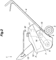
- the snow blower 1 includes a main body 2, a pair of wheels 3 provided at a lower rear part of the main body 2, and a handle bar 4 extending rearward and upward from the main body 2.
- the main body 2 includes a main body frame 5, an auger housing 6 provided in a front part of the main body frame 5, an auger 7 rotatably supported by the auger housing 6 therein, and an internal combustion engine 10 mounted on an upper rear part of the main body frame 5 to drive the auger 7.
- the snow blower 1 further includes an outer cover 11 provided on the upper part of the main body frame 5 to cover the internal combustion engine 10, a chute 12 extending upward from the auger housing 6 through the outer cover 11, and a guide cone 13 provided in an upper end of the chute 12.
- the auger housing 6 has an open side facing forward and downward.
- the auger 7 is rotatably supported by the auger housing 6 about a laterally extending rotary shaft, and is exposed in the forward and downward direction from the auger housing 6.
- the auger 7 is connected to a crankshaft 15 of the internal combustion engine 10 via a belt and pulley mechanism 16.
- the auger 7 rotates under the driving force of the internal combustion engine 10. As the auger 7 rotates, the snow is scraped into the auger housing 6.
- a rotating impeller (not shown) provided in the chute 12 discharges the snow scraped into the auger housing 6 to the outside through the chute 12.
- the guide cone 13 adjusts the direction in which the snow is discharged from the chute 12.
- the internal combustion engine 10 consists of a single-cylinder four-stroke engine, and is provided with an internal combustion engine main body 26 that includes a crankcase 21, a cylinder block 22 provided on top of the crankcase 21, a cylinder head 23 provided on top of the cylinder block 22, and a head cover 24 provided on top of the cylinder head 23.
- the crankcase 21 internally defines a crank chamber 28 that houses the crankshaft 15.
- the cylinder block 22 internally defines a cylinder 29 communicating with the crank chamber 28.
- a piston 31 is slidably received in the cylinder 29.
- the piston 31 is connected to the crankshaft 15 via a connecting rod.
- the cylinder head 23 that closes the upper end of the cylinder 29 is provided with an intake port 32 and an exhaust port 33 that communicate with the combustion chamber formed by the cylinder 29.
- the head cover 24 defines a valve actuation chamber jointly with the cylinder head 23.
- the internal combustion engine 10 is a single cylinder engine, but may also be a multi-cylinder engine.
- the crankcase 21 consists of a first case half 21A and a second case half 21B that are joined to each other about a surface obliquely intersecting the axis of the crankshaft 15.
- the first case half 21A, the cylinder block 22, and the cylinder head 23 form an integrally cast member or an upper block 35.
- the second case half 21B and the head cover 24 consist of separate members fastened to the upper block 35.
- the internal combustion engine main body 26 is attached to the main body frame 5 such that the cylinder axis thereof is substantially parallel to the vertical direction and the crank axis extends laterally. Note that the cylinder axis of the internal combustion engine 10 may be slightly inclined backward depending on the operating condition of the snow blower 1.
- the intake port 32 is provided on the rear side of the cylinder head 23, and the exhaust port 33 is provided on the front side of the cylinder head 23.
- a carburetor 40 is provided on the rear side of the cylinder head 23. As shown in Figure 4B , the carburetor 40 is provided with a carburetor body 43 that internally defines an intake passage 41 extending in the fore and aft direction, and a fuel chamber 42 positioned under the intake passage 41. The rear end of the intake passage 41 opens rearward at a rear wall 43A of a carburetor body 43 of the carburetor 40, and forms an air inlet port 44.
- the carburetor body 43 is fastened to the cylinder block 22, and the front end of the intake passage 41 is connected to the intake port 32.
- the carburetor body 43 is connected to the cylinder block 22 via an intake pipe or a passage member, instead of being directly connected to the intake port 32.
- a venturi 46 is formed in a middle part of the intake passage 41.
- a fuel supply passage 47 extending from the fuel chamber 42 has an open end located in the venturi 46.
- a pair of butterfly valves 48 are provided before and after the venturi 46 of the intake passage 41, respectively.
- a muffler 51 connected to the exhaust port 33 is provided on the front side surface of the cylinder head 23.
- the right end of the crankshaft 15 projecting rightward from the right end surface of the crankcase 21 is fitted with a flywheel, a cooling fan, and a recoil starter in a per se known manner.
- An engine cover 53 is provided on the right side of the crankcase 21 to cover the flywheel, the cooling fan, and the recoil starter.
- the engine cover 53 forms a cooling air passage jointly with the internal combustion engine main body 26.
- the cooling air drawn into the cooling air passage by the cooling fan cools the internal combustion engine main body 26.
- the left end of the crankshaft 15 projecting leftward from the left side surface of the crankcase 21 is fitted with a pulley forming a part of the belt and pulley mechanism 16.
- a breather chamber 55 communicating with the crank chamber 28 is formed on the rear side of the crankcase 21.
- the breather chamber 55 is formed by a recess formed on the rear side of the crankcase 21 and a lid 56 closing the recess.
- a plurality of partition walls (baffle plates) are provided in the breather chamber 55 so that a meandering flow path is defined.
- the lid 56 is provided with an outlet hole 57 that is passed through the lid 56 and communicates with the breather chamber 55.
- An inlet end 60A of a breather tube 60 is connected to the outlet hole 57.
- a cover member 62 is fastened to the rear wall 43A of the carburetor body 43.
- the cover member 62 is formed of a fire-resistant resin material or metal material.
- the cover member 62 may be formed of a sheet metal member.
- the cover member 62 has a front wall 65A that faces the air inlet port 44 of the carburetor 40 via a certain gap.
- the cover member 62 has a function of protecting other members from backfire that may issue from the air inlet port 44 of the carburetor 40.
- the cover member 62 includes a first member 64 and a second member 65 fastened to the first member 64.
- the first member 64 includes a base plate 64A fastened to the rear surface of the carburetor body 43.
- the base plate 64A has a major plane facing in the fore and aft direction, and extends along the rear wall 43A of the carburetor body 43.
- the base plate 64A is provided with a through hole 67 at a part thereof facing the air inlet port 44.
- the through hole 67 is formed substantially in the same shape (conformal) as the air inlet port 44 and is connected to the air inlet port 44.
- the base plate 64A is fastened to the rear wall 43A of the carburetor body 43 by a pair of bolts 68 arranged on the left and right of the through hole 67.
- the left end of the base plate 64A protrudes leftward from the left end of the rear wall 43A of the carburetor body 43, and the right end of the base plate 64A protrudes rightward from the right end of the rear wall 43A of the carburetor body 43.
- the first member 64 has an upper wall 64B protruding from the upper edge of the base plate 64A in a direction (rearward) facing away from the carburetor body 43.
- the upper wall 64B is formed in a plate shape, and has a major plane facing vertically.
- the base plate 64A and the upper wall 64B may be formed by bending a continuous piece of metal plate.
- the upper wall 64B is bent relative to the base plate 64A by about 90 degrees, and extends laterally along the upper edge of the base plate 64A.
- the second member 65 includes the front wall 65A facing the base plate 64A via a gap, a lower wall 65B extending from the lower edge of the front wall 65A toward the base plate 64A, and a pair of legs 65C extending from the lateral sides of the front wall 65A toward the base plate 64A and fastened to the base plate 64A.
- the free end of the upper wall 64B of the first member 64 extends beyond the upper edge of the front wall 65A, and the upper edge of the front wall 65A abuts against or in close proximity to the upper wall 64B.
- the front wall 65A, the lower wall 65B, and the legs 65C are formed by bending a continuous piece of metal plate.
- the front wall 65A has a plate shape having a major plane facing in the fore and aft direction, and opposes the air inlet port 44 and the through hole 67.
- the front wall 65A When viewed from the axial direction of the air inlet port 44, the front wall 65A is larger than the air inlet port 44. In other words, when viewed from the axial direction of the air inlet port 44, the entire area of the air inlet port 44 overlaps the front wall 65A.
- Each leg 65C includes a side wall 65D extending substantially perpendicular from the corresponding side edge of the front wall 65A toward the base plate 64A, and a flange 65E extending substantially perpendicular from the free end edge of the side wall 65D and abutting onto the base plate 64A.
- the flange 65E is provided with a mounting hole, and is fastened to the base plate 64A (or the part thereof extending laterally beyond the corresponding side end of the carburetor body 43) by a fastener such as a bolt 71.
- Each side wall 65D has a laterally facing major plane, and has a substantially same vertical expanse as the front wall 65A.
- the lower wall 65B is formed in a plate shape having a vertically facing major plane.
- the lower wall 65B extends substantially perpendicularly to the front wall 65A toward the base plate 64A, and also extends laterally along the lower edge of the front wall 65A.
- the lower wall 65B is formed by being bent from the front wall 65A.
- a reinforcing rib 73 is formed at a boundary between the lower wall 65B and the front wall 65A so that the relative angle between the lower wall 65B and the front wall 65A may remain fixed.
- the lower wall 65B has a cover member opening 74 that is passed thorough vertically, and a tube support portion 75 that supports the outlet end 60B of the breather tube 60.
- the cover member opening 74 is formed as a rectangular cutout extending from the side edge of the lower wall 65B, and is positioned on the left hand side of the lower wall 65B.
- the tube support portion 75 is disposed on the part of the lower wall 65B located on the right side of the cover member opening 74.
- the tube support portion 75 includes a support hole 75A vertically passed through the lower wall 65B, and a cylindrical boss portion 75B protruding upward from the peripheral edge of the support hole 75A.
- the tube support portion 75 may be formed by burring.
- the tube support portion 75 may also be provided on the front wall 65A or the side wall 65D.
- a space 77 surrounded by the base plate 64A, the front wall 65A, the upper wall 64B, the two legs 65C, and the lower wall 65B is defined.
- the space 77 is located between the rear wall 43A of the carburetor body 43 and the front wall 65A.
- the upper wall 64B covers the gap between the front wall 65A and the carburetor 40 from above. It is preferable that the free end of the upper wall 64B is in contact with the front wall 65A and the legs 65C, but a slight gap may be formed between the upper wall 64B and the front wall 65A and/or between upper wall 64B and the legs 65C.
- the lower wall 65B is in contact with the base plate 64A and/or one of the legs 65C, but a slight gap may be formed between the lower wall 65B and the base plate 64A and/or between the lower wall 65B and one of the legs 65C.
- the outlet end 60B of the breather tube 60 is inserted into the tube support portion 75 from below and fixed therein.
- the outlet end 60B of the breather tube 60 is supported by the cover member 62.
- the outlet end 60B of the breather tube 60 is fixed to the tube support portion 75 by its own elasticity.
- the outlet end 60B of the breather tube 60 is fixed to the tube support portion 75 by an adhesive, a stopper, or the like.
- the breather tube 60 is placed substantially vertically along the cylinder block 22 with a slightly spaced relationship to the cylinder block 22.
- the breather tube 60 has a bent portion 60C between the inlet end 60A and the outlet end 60B.
- the section of the breather tube 60 downstream of the bent portion 60C (on the side of the inlet end 60A) may be referred to as a downstream portion 60D
- the section of the breather tube 60 upstream of the bent portion 60C on the side of the outlet end 60B
- the gap between the breather tube 60 and the cylinder block 22 is larger in the downstream portion 60D than in the upstream portion 60E.
- the downstream portion 60D receives less heat from the cylinder block 22 than the upstream portion 60E so that the temperature of the blow-by gas drawn into the carburetor 40 decreases so that the volumetric efficiency of the internal combustion engine 10 increases, and the combustion efficiency improves.
- the bent portion 60C may be omitted.
- the carburetor 40, the cover member 62 and the breather tube 60 are arranged inside the outer cover 11.
- the outlet end 60B of the breather tube 60 is passed through the tube support portion 75 and the outlet end opening of the breather tube 60 faces upward.
- the outlet end 60B of the breather tube 60 projects above the upper surface of the lower wall 65B.
- the outlet end 60B of the breather tube 60 is disposed in the space 77 defined between the front wall 65A and the rear wall 43A of the carburetor 40.
- the outlet end 60B or, more precisely, the outlet end opening of the breather tube 60 is disposed below the center of the air inlet port 44.
- the center C1 of the air inlet port 44 of the carburetor 40 is located, as viewed from an axial direction of the air inlet port 44, between a second line L2 which is orthogonal to a first line L1 extending between the center C2 of an outlet end opening of the outlet end 60B of the breather tube 60 and the center C3 of the cover member opening 74 and extends through the center C2 of the outlet end opening of the breather tube 60, and a third line L3 orthogonal to the first line L1 and extending through the center C3 of the cover member opening 74.
- the distance D1 between the center C2 of the outlet end opening of the outlet end 60B of the breather tube 60 and the center C1 of the air inlet port 44 is shorter than the distance D2 between the center C2 of the outlet end opening of the outlet end 60B of the breather tube 60 and the center C3 of the cover member opening 74.
- the air inlet port 44 of the carburetor 40 and the cover member opening 74 are dimensioned so that the space 77 defined by the cover member 62 jointly with an outer surface of the carburetor body 43 is placed under a negative pressure due to a reciprocating movement of a piston 31 of the internal combustion engine 10.
- an open space 81 is formed under the cover member 62 so that liquid that could be discharged from the cover member 62 may not contaminate or otherwise adversely affect a component part or a part of the internal combustion engine 10.
- components or parts of the internal combustion engine 10 which are required to avoid contact with the liquid that could be discharged from the cover member 62 are positioned outside of this open space 81.
- a notch 84 is formed in the upper edge of the side wall 65D of one of the legs 65C of the second member 65 remote from the tube support portion 75.
- the notch 84 defines a hole through which a vent tube 83 is passed in cooperation with the upper wall 64B of the first member 64.
- the vent tube 83 extends vertically along the rear side of the cylinder block 22, and has an upper end which is passed through this notch 84 and connected to an upper part of a fuel chamber of the carburetor 40, and a lower end which communicates with the atmosphere.
- the mode of operation of this internal combustion engine 10 is described in the following.
- the blow-by gas generated in the crank chamber 28 is discharged therefrom via the breather chamber 55 and the inlet end of the breather tube 60, and is then expelled into the space 77 defined by the cover member 62 via the outlet end 60B of the breather tube 60. Thereafter, the blow-by gas is drawn into the air inlet port 44 by the negative pressure generated at the air inlet port 44, and is supplied to the cylinder 29 through the carburetor 40 and the intake port 32.
- the cover member 62 which has the primary function of protecting other members from backfire that can issue from the air inlet port 44 of the carburetor 40 supports the outlet end of the breather tube 60 as the secondary function thereof.
- the outlet end of the breather tube 60 can be positioned on the upstream side of the carburetor 40 without forming an intake passage by using various component parts. Further, since the outlet end 60B of the breather tube 60 is disposed between the front wall 65A of the cover member 62 and the carburetor body 43, the blow-by gas flowing out of the outlet end of the breather tube 60 is prevented from being released to the atmosphere.
- the cover member opening 74 is formed in the lower wall 65B, the air can be supplied to the carburetor 40 through the cover member opening 74, and the liquid such as oil that may be deposited inside the cover member 62 is discharged to the outside through the cover member opening 74. Since an open space 81 in which no essential device such as an electric device is placed is formed below the cover member 62, even if liquid should drip down from the cover member 62, essential devices are protected from the deposition of such liquid.
- the outlet end 60B of the breather tube 60 is disposed higher than the inlet end 60A thereof, and supported by the tube support portion 75 in such a manner that the opening of the outlet end 60B of the breather tube 60 faces upward, liquid such as oil which may be deposited in the breather tube 60 is caused to flow downward toward the inlet end 60A of the breather tube 60 under the gravitational force. As a result, liquid such as oil is prevented from being discharged from the outlet end 60B of the breather tube 60 to the interior of the cover member 62.
- the outlet end 60B of the breather tube 60 protrudes above the upper surface of the lower wall 65B, and is positioned near the air inlet port 44. As a result, the blow-by gas can be prevented from flowing out of the space 77 defined in the cover member 62. Further, since the outlet end 60B of the breather tube 60 is disposed below the center of the air inlet port 44, liquid which may be discharged from the outlet end 60B of the breather tube 60 is prevented from being drawn into the air inlet port 44.
- the center C1 of the air inlet port 44 of the carburetor 40 is located, as viewed from an axial direction of the air inlet port 44, between a second line L2 which is orthogonal to a first line L1 extending between the center C2 of the outlet end opening of the outlet end 60B of the breather tube 60 and the center C3 of the cover member opening 74 and extends through the center C2 of the outlet end opening of the breather tube 60, and a third line L3 orthogonal to the first line L1 and extending through the center C3 of the cover member opening 74.
- the distance D1 between the center C2 of the outlet end opening of the breather tube 60 and the center C1 of the air inlet port 44 is shorter than the distance D2 between the center C2 of the outlet end opening of the outlet end 60B of the breather tube 60 and the center C3 of the cover member opening 74. Therefore, the blow-by gas is prevented from being released to the outside of the cover member 62 through the cover member opening 74.
- the breather tube 60 is arranged inside the outer cover 11, the breather tube 60 is protected from the influences of the outside air temperature. Therefore, it is possible to prevent the moisture contained in the blow-by gas from freezing in the breather tube 60.
- the cover member 62 can be attached to the carburetor body 43 to define the space 77 for positioning the outlet end 60B of the breather tube 60.
- Figure 9 show a cover member 62 according to a second embodiment of the present invention.
- the cover member 62 consists solely of the second member 65.
- the legs 65C are directly fastened to the rear wall 43A of the carburetor body 43.
- the upper wall 64B in this case extends from the carburetor body 43 to fill the gap between the upper edge of the front wall 65A and the rear wall 43A of the carburetor body 43.
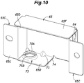
- FIG. 10 shows a cover member 62 according to a third embodiment of the present invention.
- the cover member 62 consists solely of the second member 65.
- an upper wall 65F extends from the upper edge of the front wall 65A toward the rear wall 43A of the carburetor body 43.
- the internal combustion engine 10 according to the present invention was applied to a snow blower 1.
- the internal combustion engine 10 can also be applied to other work devices such as cultivators, weed cutters, sprayers, so on.
Landscapes
- Engineering & Computer Science (AREA)
- Chemical & Material Sciences (AREA)
- Combustion & Propulsion (AREA)
- Mechanical Engineering (AREA)
- General Engineering & Computer Science (AREA)
- Manufacturing & Machinery (AREA)
- Lubrication Details And Ventilation Of Internal Combustion Engines (AREA)
Description
- The present invention relates to an internal combustion engine.
- In an internal combustion engine, it is known to return blow-by gas generated in a crank chamber to an intake pipe via a breather tube (see
JPH10-159534A - The intake pipe, the air cleaner, and the muffler of an internal combustion engine are designed in different ways for different applications. For instance, the surrounding air may be directly drawn into an air inlet port of the carburetor for a certain application, instead of using an air cleaner and an intake pipe. In such a case, there is a need to create an intake passage within the carburetor to allow the blow-by gas to be drawn into the intake system of the internal combustion engine. This requires the carburetor to be re-designed specifically for this particular application.
-
US 3889649 discloses an internal combustion engine, comprising: a carburetor connected to an intake port of an internal combustion engine; an intake unit having a cylindrical metal top cover facing an air inlet port of the carburetor; and a rubber feed tube having an input end connected to a crank chamber of the internal combustion engine main body, and a tubing section supported by an element of the intake unit. The tubing section is located between the carburetor and the top cover. There, an intake passage of the carburetor extends in the up and down direction and an air inlet port faces upward. And the top cover is located above the air inlet port of the carburetor, and the tube section is located above the air inlet port of the carburetor. Therefore, any liquid that leaks from the tube section enters the air inlet port and is not expelled from the intake unit. -
JP 2000 345 930 A claim 1. -
JP S50 20014 U6 -
US 2013/098325 A1 discloses an air supply device having a preventive plate attached to a mixture-side opening communicated with the carburetor mixture passage of the carburetor. The preventive plate traps the blow-back fuel from the mixture-side opening. - In view of such a problem of the prior art, a primary object of the present invention is to provide an internal combustion engine which allows an outlet end of a breather tube to be connected to an upstream side of a carburetor without requiring an intake pipe and without requiring a major modification of the carburetor.
- To achieve such an object, the present invention provides an internal combustion engine (10) according to
claim 1. - The internal combustion engine comprises: a carburetor (40) connected to an intake port (32) of an internal combustion engine main body (26); a fire-resistant cover member (62) having a front wall (65A) facing an air inlet port (44) of the carburetor; and a breather tube (60) having an inlet end (60A) connected to a crank chamber (28) of the internal combustion engine main body, and an outlet end (60B) supported by the cover member at a position located between the front wall and the carburetor.
- The cover member has the function of protecting other components surrounding the carburetor from the backfire which may issue from the air inlet port of the carburetor. According to the present invention, the cover member is conveniently used for supporting the outlet end of the breather tube. Thus, the outlet end of the breather tube can be communicated with the air inlet port of the carburetor without requiring any major additional member or component. Further, even though the outlet end of the breather tube is simply positioned between the front wall of the cover member and the carburetor without using any air tight fitting or the like, owing to the existence of the flow of the fresh intake air into the air inlet port of the carburetor, the blow-by gas flowing out of the outlet end of the breather tube can be entirely drawn into the air inlet port of the carburetor without the risk of releasing the blow-by gas to the atmosphere.
- The cover member further includes a lower wall (65B) extending from a lower edge of the front wall toward the carburetor, and having a cover member opening (74) passed vertically through the lower wall.
- The fresh air can be drawn into the air inlet port of the carburetor via the cover member opening in the lower wall, and any liquid such as moisture and oil which may deposit inside the cover member can be expelled from the cover member opening.
- Preferably, an open space (81) is defined under the cover member.
- Thereby, the liquid which may drip down from the cover member opening is prevented from contaminating any auxiliary device or the engine main body.
- Preferably, the lower wall is provided with a tube supporting portion (75) receiving the outlet end of the breather tube therein, and the outlet end of the breather tube is located higher than the inlet end of the breather tube, the outlet end of the breather tube having an outlet end opening facing upward.
- The liquid such as oil that may be present in the breather tube flows toward the inlet end of the breather tube under the gravitational force so that the liquid is prevented from reaching the interior of the cover member or into the air inlet port of the carburetor.
- Preferably, the outlet end of the breather tube projects upward from an upper surface of the lower wall.
- Thereby, the outlet end of the breather tube is placed near the intake port of the carburetor so that the blow-gas is prevented from being released to the atmosphere.
- Preferably, the outlet end opening of the breather tube is located lower than a center of the air inlet port of the carburetor.
- Thereby, the liquid which could be released from the outlet end of the breather tube is prevented from being drawn into the air inlet port of the carburetor.
- Preferably, a center (C1) of the air inlet port of the carburetor is located, as viewed from an axial direction of the air inlet port, between a second line (L2) which is orthogonal to a first line (L1) extending between a center (C2) of the outlet end opening of the outlet end of the breather tube and a center (C3) of the cover member opening and extends through the center (C2) of the outlet end opening of the breather tube, and a third line (L3) orthogonal to the first line (L1) and extending through the center (C3) of the cover member opening.
- Thereby, the blow-by gas expelled from the outlet end of the breather tube passes by the air inlet port of the carburetor, and is drawn into the air inlet port of the carburetor before reaching the cover member opening so that the blow-by gas is prevented from being released to the atmosphere via the cover member opening.
- Preferably, a distance (D1) between a center (C2) of the outlet end opening of the breather tube and a center (C1) of the air inlet opening of the carburetor is smaller than a distance (D2) between the center (C2) the outlet end opening of the breather tube and a center (C3) of the cover member opening.
- Since the air inlet opening of the carburetor is nearer to the outlet end opening of the breather tube than the cover member opening, the blow-by gas is drawn into the air inlet opening of the carburetor without being released to the atmosphere via the cover member opening in a particularly reliable manner.
- Preferably, the air inlet port of the carburetor and the cover member opening are dimensioned so that a space defined by the cover member jointly with an outer surface of the carburetor is placed under a negative pressure due to a reciprocating movement of a piston (31) of the internal combustion engine.
- Thereby, the blow-by gas is drawn into the air inlet opening of the carburetor without being released to the atmosphere in a particularly reliable manner.
- Preferably, the internal combustion engine further includes an outer cover (11) covering the internal combustion engine main body, and the carburetor, the cover member and the breather tube are placed inside the outer cover.
- Thereby, the breather tube is protected from influences of the surrounding temperature since the interior of the outer cover is maintained at a raised temperature owing to the heat of the engine. Therefore, the moisture contained in the blow-by gas is prevented from freezing inside the breather tube.
- Preferably, the cover member is made of stamp formed sheet metal.
- Thereby, the manufacturing process is simplified, and the manufacturing cost is minimized.
- Preferably, the cover member is provided with a pair of legs (65C) extending from lateral sides of the front wall and attached to the carburetor, and an upper wall (64B) extending from an upper edge of the front wall to a part at least adjoining an outer surface of the carburetor or from the carburetor to a part at least adjoining the front wall.
- Thereby, the space defined between the front wall and the outer surface of the carburetor can be closed from above with the upper wall which can be formed simply by bending the sheet metal or adding a strip of sheet metal.
- According to a preferred embodiment of the present invention, the air inlet port of the carburetor faces in a lateral direction, and the cover member includes a first member (64) and a second member (65) fastened to the first member, wherein the first member includes a base plate (64A) secured to an end surface of the carburetor and having a through hole (67) communicating with the air inlet port of the carburetor, and an upper wall extending from an upper edge of the base plate away from the carburetor, and the second member includes the front wall (65A) opposing the base plate, a lower wall (65B) extending from a lower edge of the front wall toward the base plate, and a pair of legs (65C) extending from either side edge of the front wall and attached to the base plate, the lower wall being provided with a cover member opening (74) passed vertically therethrough.
- Thereby, even when the carburetor is small in size, the cover member for defining the space for placing the outlet end of the breather tube can be manufactured both easily and economically.
- The present invention thus provides an internal combustion engine which allows an outlet end of a breather tube to be connected to an upstream side of a carburetor without requiring an intake pipe and without requiring a major modification of the carburetor.
-
-
Figure 1 is a perspective view of a snow blower to which an internal combustion engine according to a first embodiment of the present invention is applied: -
Figure 2 is a side view of the snow blower; -
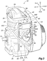
Figure 3 is a perspective view of the internal combustion engine; -
Figure 4A is a schematic sectional view of the internal combustion engine; -
Figure 4B is an enlarged view of a part indicated by letter B inFigure 4A ; -
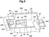
Figure 5 is a perspective view of a carburetor and a cover member of the internal combustion engine as viewed from below; -
Figure 6 is a fragmentary rear view of the internal combustion engine partly in section; -
Figure 7 is an enlarged sectional view of the cover member; -
Figure 8 is a perspective view of a second member of the cover member; -
Figure 9 is a view similar toFigure 5 showing a cover member according to a second embodiment of the present invention; and -
Figure 10 is a view similar toFigure 8 showing a cover member according to a third embodiment of the present invention. - An internal combustion engine according to the present invention as applied to a snow blower is described in the following with reference to the appended drawings.
- As shown in
Figures 1 and2 , thesnow blower 1 includes amain body 2, a pair ofwheels 3 provided at a lower rear part of themain body 2, and ahandle bar 4 extending rearward and upward from themain body 2. Themain body 2 includes amain body frame 5, anauger housing 6 provided in a front part of themain body frame 5, anauger 7 rotatably supported by theauger housing 6 therein, and aninternal combustion engine 10 mounted on an upper rear part of themain body frame 5 to drive theauger 7. Thesnow blower 1 further includes anouter cover 11 provided on the upper part of themain body frame 5 to cover theinternal combustion engine 10, achute 12 extending upward from theauger housing 6 through theouter cover 11, and aguide cone 13 provided in an upper end of thechute 12. - The
auger housing 6 has an open side facing forward and downward. Theauger 7 is rotatably supported by theauger housing 6 about a laterally extending rotary shaft, and is exposed in the forward and downward direction from theauger housing 6. Theauger 7 is connected to acrankshaft 15 of theinternal combustion engine 10 via a belt andpulley mechanism 16. Theauger 7 rotates under the driving force of theinternal combustion engine 10. As theauger 7 rotates, the snow is scraped into theauger housing 6. A rotating impeller (not shown) provided in thechute 12 discharges the snow scraped into theauger housing 6 to the outside through thechute 12. Theguide cone 13 adjusts the direction in which the snow is discharged from thechute 12. - As shown in
Figures 3 and4A , theinternal combustion engine 10 consists of a single-cylinder four-stroke engine, and is provided with an internal combustion enginemain body 26 that includes acrankcase 21, acylinder block 22 provided on top of thecrankcase 21, acylinder head 23 provided on top of thecylinder block 22, and ahead cover 24 provided on top of thecylinder head 23. Thecrankcase 21 internally defines acrank chamber 28 that houses thecrankshaft 15. - The
cylinder block 22 internally defines acylinder 29 communicating with thecrank chamber 28. Apiston 31 is slidably received in thecylinder 29. Thepiston 31 is connected to thecrankshaft 15 via a connecting rod. Thecylinder head 23 that closes the upper end of thecylinder 29 is provided with anintake port 32 and anexhaust port 33 that communicate with the combustion chamber formed by thecylinder 29. Thehead cover 24 defines a valve actuation chamber jointly with thecylinder head 23. In the present embodiment, theinternal combustion engine 10 is a single cylinder engine, but may also be a multi-cylinder engine. - In the present embodiment, the
crankcase 21 consists of afirst case half 21A and asecond case half 21B that are joined to each other about a surface obliquely intersecting the axis of thecrankshaft 15. Thefirst case half 21A, thecylinder block 22, and thecylinder head 23 form an integrally cast member or anupper block 35. Thesecond case half 21B and thehead cover 24 consist of separate members fastened to theupper block 35. - The internal combustion engine
main body 26 is attached to themain body frame 5 such that the cylinder axis thereof is substantially parallel to the vertical direction and the crank axis extends laterally. Note that the cylinder axis of theinternal combustion engine 10 may be slightly inclined backward depending on the operating condition of thesnow blower 1. Theintake port 32 is provided on the rear side of thecylinder head 23, and theexhaust port 33 is provided on the front side of thecylinder head 23. - A
carburetor 40 is provided on the rear side of thecylinder head 23. As shown inFigure 4B , thecarburetor 40 is provided with acarburetor body 43 that internally defines anintake passage 41 extending in the fore and aft direction, and afuel chamber 42 positioned under theintake passage 41. The rear end of theintake passage 41 opens rearward at arear wall 43A of acarburetor body 43 of thecarburetor 40, and forms anair inlet port 44. Thecarburetor body 43 is fastened to thecylinder block 22, and the front end of theintake passage 41 is connected to theintake port 32. In another embodiment, thecarburetor body 43 is connected to thecylinder block 22 via an intake pipe or a passage member, instead of being directly connected to theintake port 32. - A
venturi 46 is formed in a middle part of theintake passage 41. Afuel supply passage 47 extending from thefuel chamber 42 has an open end located in theventuri 46. A pair ofbutterfly valves 48 are provided before and after theventuri 46 of theintake passage 41, respectively. - As shown in
Figures 3 and4A , amuffler 51 connected to theexhaust port 33 is provided on the front side surface of thecylinder head 23. The right end of thecrankshaft 15 projecting rightward from the right end surface of thecrankcase 21 is fitted with a flywheel, a cooling fan, and a recoil starter in a per se known manner. Anengine cover 53 is provided on the right side of thecrankcase 21 to cover the flywheel, the cooling fan, and the recoil starter. The engine cover 53 forms a cooling air passage jointly with the internal combustion enginemain body 26. The cooling air drawn into the cooling air passage by the cooling fan cools the internal combustion enginemain body 26. The left end of thecrankshaft 15 projecting leftward from the left side surface of thecrankcase 21 is fitted with a pulley forming a part of the belt andpulley mechanism 16. - A
breather chamber 55 communicating with thecrank chamber 28 is formed on the rear side of thecrankcase 21. Thebreather chamber 55 is formed by a recess formed on the rear side of thecrankcase 21 and alid 56 closing the recess. A plurality of partition walls (baffle plates) are provided in thebreather chamber 55 so that a meandering flow path is defined. Thelid 56 is provided with anoutlet hole 57 that is passed through thelid 56 and communicates with thebreather chamber 55. Aninlet end 60A of abreather tube 60 is connected to theoutlet hole 57. - A
cover member 62 is fastened to therear wall 43A of thecarburetor body 43. Thecover member 62 is formed of a fire-resistant resin material or metal material. For example, thecover member 62 may be formed of a sheet metal member. Thecover member 62 has afront wall 65A that faces theair inlet port 44 of thecarburetor 40 via a certain gap. Thecover member 62 has a function of protecting other members from backfire that may issue from theair inlet port 44 of thecarburetor 40. - In the present embodiment, as shown in
Figures 5 and6 , thecover member 62 includes afirst member 64 and asecond member 65 fastened to thefirst member 64. Thefirst member 64 includes abase plate 64A fastened to the rear surface of thecarburetor body 43. Thebase plate 64A has a major plane facing in the fore and aft direction, and extends along therear wall 43A of thecarburetor body 43. Thebase plate 64A is provided with a throughhole 67 at a part thereof facing theair inlet port 44. The throughhole 67 is formed substantially in the same shape (conformal) as theair inlet port 44 and is connected to theair inlet port 44. Thebase plate 64A is fastened to therear wall 43A of thecarburetor body 43 by a pair ofbolts 68 arranged on the left and right of the throughhole 67. The left end of thebase plate 64A protrudes leftward from the left end of therear wall 43A of thecarburetor body 43, and the right end of thebase plate 64A protrudes rightward from the right end of therear wall 43A of thecarburetor body 43. - The
first member 64 has anupper wall 64B protruding from the upper edge of thebase plate 64A in a direction (rearward) facing away from thecarburetor body 43. Theupper wall 64B is formed in a plate shape, and has a major plane facing vertically. Thebase plate 64A and theupper wall 64B may be formed by bending a continuous piece of metal plate. Theupper wall 64B is bent relative to thebase plate 64A by about 90 degrees, and extends laterally along the upper edge of thebase plate 64A. - As shown in
Figures 5 to 8 , thesecond member 65 includes thefront wall 65A facing thebase plate 64A via a gap, alower wall 65B extending from the lower edge of thefront wall 65A toward thebase plate 64A, and a pair oflegs 65C extending from the lateral sides of thefront wall 65A toward thebase plate 64A and fastened to thebase plate 64A. The free end of theupper wall 64B of thefirst member 64 extends beyond the upper edge of thefront wall 65A, and the upper edge of thefront wall 65A abuts against or in close proximity to theupper wall 64B. Thefront wall 65A, thelower wall 65B, and thelegs 65C are formed by bending a continuous piece of metal plate. - The
front wall 65A has a plate shape having a major plane facing in the fore and aft direction, and opposes theair inlet port 44 and the throughhole 67. When viewed from the axial direction of theair inlet port 44, thefront wall 65A is larger than theair inlet port 44. In other words, when viewed from the axial direction of theair inlet port 44, the entire area of theair inlet port 44 overlaps thefront wall 65A. - Each
leg 65C includes aside wall 65D extending substantially perpendicular from the corresponding side edge of thefront wall 65A toward thebase plate 64A, and aflange 65E extending substantially perpendicular from the free end edge of theside wall 65D and abutting onto thebase plate 64A. Theflange 65E is provided with a mounting hole, and is fastened to thebase plate 64A (or the part thereof extending laterally beyond the corresponding side end of the carburetor body 43) by a fastener such as abolt 71. Eachside wall 65D has a laterally facing major plane, and has a substantially same vertical expanse as thefront wall 65A. - As shown in
Figure 8 , thelower wall 65B is formed in a plate shape having a vertically facing major plane. Thelower wall 65B extends substantially perpendicularly to thefront wall 65A toward thebase plate 64A, and also extends laterally along the lower edge of thefront wall 65A. Thelower wall 65B is formed by being bent from thefront wall 65A. A reinforcingrib 73 is formed at a boundary between thelower wall 65B and thefront wall 65A so that the relative angle between thelower wall 65B and thefront wall 65A may remain fixed. - The
lower wall 65B has acover member opening 74 that is passed thorough vertically, and atube support portion 75 that supports theoutlet end 60B of thebreather tube 60. In the present embodiment, thecover member opening 74 is formed as a rectangular cutout extending from the side edge of thelower wall 65B, and is positioned on the left hand side of thelower wall 65B. Thetube support portion 75 is disposed on the part of thelower wall 65B located on the right side of thecover member opening 74. Thetube support portion 75 includes asupport hole 75A vertically passed through thelower wall 65B, and acylindrical boss portion 75B protruding upward from the peripheral edge of thesupport hole 75A. When thesecond member 65 is formed from a metal plate, thetube support portion 75 may be formed by burring. Thetube support portion 75 may also be provided on thefront wall 65A or theside wall 65D. - By fastening the
first member 64 and thesecond member 65 to each other, aspace 77 surrounded by thebase plate 64A, thefront wall 65A, theupper wall 64B, the twolegs 65C, and thelower wall 65B is defined. Thespace 77 is located between therear wall 43A of thecarburetor body 43 and thefront wall 65A. Theupper wall 64B covers the gap between thefront wall 65A and thecarburetor 40 from above. It is preferable that the free end of theupper wall 64B is in contact with thefront wall 65A and thelegs 65C, but a slight gap may be formed between theupper wall 64B and thefront wall 65A and/or betweenupper wall 64B and thelegs 65C. Similarly, it is preferable that thelower wall 65B is in contact with thebase plate 64A and/or one of thelegs 65C, but a slight gap may be formed between thelower wall 65B and thebase plate 64A and/or between thelower wall 65B and one of thelegs 65C. - As shown in
Figure 6 , theoutlet end 60B of thebreather tube 60 is inserted into thetube support portion 75 from below and fixed therein. Thus, theoutlet end 60B of thebreather tube 60 is supported by thecover member 62. In the present embodiment, theoutlet end 60B of thebreather tube 60 is fixed to thetube support portion 75 by its own elasticity. In another embodiment, theoutlet end 60B of thebreather tube 60 is fixed to thetube support portion 75 by an adhesive, a stopper, or the like. - The
breather tube 60 is placed substantially vertically along thecylinder block 22 with a slightly spaced relationship to thecylinder block 22. Thebreather tube 60 has abent portion 60C between the inlet end 60A and theoutlet end 60B. The section of thebreather tube 60 downstream of thebent portion 60C (on the side of theinlet end 60A) may be referred to as adownstream portion 60D, and the section of thebreather tube 60 upstream of thebent portion 60C (on the side of theoutlet end 60B) may be referred to as anupstream portion 60E. The gap between thebreather tube 60 and thecylinder block 22 is larger in thedownstream portion 60D than in theupstream portion 60E. Therefore, thedownstream portion 60D receives less heat from thecylinder block 22 than theupstream portion 60E so that the temperature of the blow-by gas drawn into thecarburetor 40 decreases so that the volumetric efficiency of theinternal combustion engine 10 increases, and the combustion efficiency improves. In order to minimize the length of thebreather tube 60, thebent portion 60C may be omitted. In this embodiment, thecarburetor 40, thecover member 62 and thebreather tube 60 are arranged inside theouter cover 11. - The
outlet end 60B of thebreather tube 60 is passed through thetube support portion 75 and the outlet end opening of thebreather tube 60 faces upward. Theoutlet end 60B of thebreather tube 60 projects above the upper surface of thelower wall 65B. Theoutlet end 60B of thebreather tube 60 is disposed in thespace 77 defined between thefront wall 65A and therear wall 43A of thecarburetor 40. Theoutlet end 60B or, more precisely, the outlet end opening of thebreather tube 60 is disposed below the center of theair inlet port 44. - As shown in
Figure 7 , the center C1 of theair inlet port 44 of thecarburetor 40 is located, as viewed from an axial direction of theair inlet port 44, between a second line L2 which is orthogonal to a first line L1 extending between the center C2 of an outlet end opening of theoutlet end 60B of thebreather tube 60 and the center C3 of thecover member opening 74 and extends through the center C2 of the outlet end opening of thebreather tube 60, and a third line L3 orthogonal to the first line L1 and extending through the center C3 of thecover member opening 74. The distance D1 between the center C2 of the outlet end opening of theoutlet end 60B of thebreather tube 60 and the center C1 of theair inlet port 44 is shorter than the distance D2 between the center C2 of the outlet end opening of theoutlet end 60B of thebreather tube 60 and the center C3 of thecover member opening 74. - Preferably, the
air inlet port 44 of thecarburetor 40 and thecover member opening 74 are dimensioned so that thespace 77 defined by thecover member 62 jointly with an outer surface of thecarburetor body 43 is placed under a negative pressure due to a reciprocating movement of apiston 31 of theinternal combustion engine 10. - As shown in
Figure 3 , anopen space 81 is formed under thecover member 62 so that liquid that could be discharged from thecover member 62 may not contaminate or otherwise adversely affect a component part or a part of theinternal combustion engine 10. In other words, components or parts of theinternal combustion engine 10 which are required to avoid contact with the liquid that could be discharged from thecover member 62 are positioned outside of thisopen space 81. - As shown in
Figures 6 and8 , anotch 84 is formed in the upper edge of theside wall 65D of one of thelegs 65C of thesecond member 65 remote from thetube support portion 75. Thenotch 84 defines a hole through which avent tube 83 is passed in cooperation with theupper wall 64B of thefirst member 64. Thevent tube 83 extends vertically along the rear side of thecylinder block 22, and has an upper end which is passed through thisnotch 84 and connected to an upper part of a fuel chamber of thecarburetor 40, and a lower end which communicates with the atmosphere. - The mode of operation of this
internal combustion engine 10 is described in the following. The blow-by gas generated in thecrank chamber 28 is discharged therefrom via thebreather chamber 55 and the inlet end of thebreather tube 60, and is then expelled into thespace 77 defined by thecover member 62 via theoutlet end 60B of thebreather tube 60. Thereafter, the blow-by gas is drawn into theair inlet port 44 by the negative pressure generated at theair inlet port 44, and is supplied to thecylinder 29 through thecarburetor 40 and theintake port 32. Thecover member 62 which has the primary function of protecting other members from backfire that can issue from theair inlet port 44 of thecarburetor 40 supports the outlet end of thebreather tube 60 as the secondary function thereof. Thus, the outlet end of thebreather tube 60 can be positioned on the upstream side of thecarburetor 40 without forming an intake passage by using various component parts. Further, since theoutlet end 60B of thebreather tube 60 is disposed between thefront wall 65A of thecover member 62 and thecarburetor body 43, the blow-by gas flowing out of the outlet end of thebreather tube 60 is prevented from being released to the atmosphere. - Since the
cover member opening 74 is formed in thelower wall 65B, the air can be supplied to thecarburetor 40 through thecover member opening 74, and the liquid such as oil that may be deposited inside thecover member 62 is discharged to the outside through thecover member opening 74. Since anopen space 81 in which no essential device such as an electric device is placed is formed below thecover member 62, even if liquid should drip down from thecover member 62, essential devices are protected from the deposition of such liquid. - Since the
outlet end 60B of thebreather tube 60 is disposed higher than the inlet end 60A thereof, and supported by thetube support portion 75 in such a manner that the opening of theoutlet end 60B of thebreather tube 60 faces upward, liquid such as oil which may be deposited in thebreather tube 60 is caused to flow downward toward theinlet end 60A of thebreather tube 60 under the gravitational force. As a result, liquid such as oil is prevented from being discharged from theoutlet end 60B of thebreather tube 60 to the interior of thecover member 62. - The
outlet end 60B of thebreather tube 60 protrudes above the upper surface of thelower wall 65B, and is positioned near theair inlet port 44. As a result, the blow-by gas can be prevented from flowing out of thespace 77 defined in thecover member 62. Further, since theoutlet end 60B of thebreather tube 60 is disposed below the center of theair inlet port 44, liquid which may be discharged from theoutlet end 60B of thebreather tube 60 is prevented from being drawn into theair inlet port 44. - The center C1 of the
air inlet port 44 of thecarburetor 40 is located, as viewed from an axial direction of theair inlet port 44, between a second line L2 which is orthogonal to a first line L1 extending between the center C2 of the outlet end opening of theoutlet end 60B of thebreather tube 60 and the center C3 of thecover member opening 74 and extends through the center C2 of the outlet end opening of thebreather tube 60, and a third line L3 orthogonal to the first line L1 and extending through the center C3 of thecover member opening 74. The distance D1 between the center C2 of the outlet end opening of thebreather tube 60 and the center C1 of theair inlet port 44 is shorter than the distance D2 between the center C2 of the outlet end opening of theoutlet end 60B of thebreather tube 60 and the center C3 of thecover member opening 74. Therefore, the blow-by gas is prevented from being released to the outside of thecover member 62 through thecover member opening 74. - Since the
breather tube 60 is arranged inside theouter cover 11, thebreather tube 60 is protected from the influences of the outside air temperature. Therefore, it is possible to prevent the moisture contained in the blow-by gas from freezing in thebreather tube 60. - Even when the
carburetor body 43 is so small that there is no available surface area to which thesecond member 65 can be fastened, owing to the use of thefirst member 64, thecover member 62 can be attached to thecarburetor body 43 to define thespace 77 for positioning theoutlet end 60B of thebreather tube 60. -
Figure 9 show acover member 62 according to a second embodiment of the present invention. In this embodiment, thecover member 62 consists solely of thesecond member 65. Thelegs 65C are directly fastened to therear wall 43A of thecarburetor body 43. Theupper wall 64B in this case extends from thecarburetor body 43 to fill the gap between the upper edge of thefront wall 65A and therear wall 43A of thecarburetor body 43. -
Figure 10 shows acover member 62 according to a third embodiment of the present invention. In this embodiment also, thecover member 62 consists solely of thesecond member 65. Instead of theupper wall 43B extending from thecarburetor body 43, anupper wall 65F extends from the upper edge of thefront wall 65A toward therear wall 43A of thecarburetor body 43. - In the foregoing embodiments, the
internal combustion engine 10 according to the present invention was applied to asnow blower 1. However, theinternal combustion engine 10 can also be applied to other work devices such as cultivators, weed cutters, sprayers, so on.
Claims (12)
- An internal combustion engine (10) comprising an internal combustion engine main body (26) that includes a crankcase (21), a cylinder block (22) provided on top of the crankcase, a cylinder head (23) provided on top of the cylinder block, and a head cover (24) provided on top of the cylinder head,wherein an upper and lower direction is along a vertical direction, a front and rear direction is perpendicular to the vertical direction, and a left and right direction is perpendicular to the vertical direction and the front and rear direction,wherein the internal combustion engine main body is attached to a main body frame (5) such that a cylinder axis thereof is substantially parallel to the vertical direction and a crank axis extends in the left and right direction, wherein the internal combustion engine further comprises:a carburetor (40) provided on a rear side of the cylinder head, the carburetor is provided with a carburetor body (43) internally having an intake passage (41) extending in the front and rear direction, a front end of the intake passage being connected to an intake port (32) of the cylinder head (23) and a rear end of the intake passage forming an air inlet port (44); anda fire-resistant cover member (62) having a front wall (65A) provided on the rear side of the cylinder head and wall facing the air inlet port via a gap, the front wall having a plate shape having a major plane facing in the front and rear direction;wherein the cover member (62) further includes a lower wall (65B) extending from a lower edge of the front wall (65A) of the cover member (62) toward the carburetor (40), and having a cover member opening (74) passed vertically through the lower wall (65B),characterized in that the engine (10) further comprises a breather tube (60) having an inlet end (60A) connected to a crank chamber (28) of the internal combustion engine main body, and an outlet end (60B) supported by the cover member at a position located between the front wall (65A) of the cover member (62) and the carburetor (40).
- The internal combustion engine according to claim 1, wherein an open space (81) is defined under the cover member.
- The internal combustion engine according to claim 1 or 2, wherein the lower wall is provided with a tube supporting portion (75) receiving the outlet end of the breather tube therein, and the outlet end of the breather tube is located higher than the inlet end of the breather tube, the outlet end of the breather tube having an outlet end opening facing upward.
- The internal combustion engine according to claim 3, wherein the outlet end of the breather tube projects upward from an upper surface of the lower wall.
- The internal combustion engine according to claim 4, wherein the outlet end opening of the breather tube is located lower than a center (C1) of the air inlet port of the carburetor.
- The internal combustion engine according to any one of claims 3 to 5, wherein a center (C1) of the air inlet port of the carburetor is located, as viewed from an axial direction of the air inlet port, between a second line (L2) which is orthogonal to a first line (L1) extending between a center (C2) of the outlet end opening of the outlet end of the breather tube and a center (C3) of the cover member opening and extends through the center (C2) of the outlet end opening of the breather tube, and a third line (L3) orthogonal to the first line (L1) and extending through the center (C3) of the cover member opening.
- The internal combustion engine according to any one of claims 3 to 6, wherein a distance (D1) between a center (C2) of the outlet end opening of the breather tube and a center (C1) of the air inlet opening of the carburetor is smaller than a distance (D2) between the center (C2) of the outlet end opening of the breather tube and a center (C3) of the cover member opening.
- The internal combustion engine according to any one of claims 1 to 7, wherein the air inlet port of the carburetor and the cover member opening are dimensioned so that a space defined by the cover member jointly with an outer surface of the carburetor is placed under a negative pressure due to a reciprocating movement of a piston (31) of the internal combustion engine.
- The internal combustion engine according to any one of claims 1 to 8, further comprising an outer cover (11) covering the internal combustion engine main body, wherein the carburetor, the cover member and the breather tube are placed inside the outer cover.
- The internal combustion engine according to any one of claims 1 to 9, wherein the cover member is made of stamp formed sheet metal.
- The internal combustion engine according to claim 10, wherein the cover member is provided with a pair of legs (65C) extending from lateral sides of the front wall (65A) provided on the rear side of the cylinder head and of the cover member (62) and attached to the carburetor (40), and an upper wall (64B) extending from an upper edge of the front wall (65A) of the cover member (62) to a part at least adjoining an outer surface of the carburetor or from the carburetor to a part at least adjoining the front wall (65A).
- The internal combustion engine according to claim 10, wherein the air inlet port of the carburetor faces in a lateral direction, and the cover member includes a first member (64) and a second member (65) fastened to the first member, wherein the first member includes a base plate (64A) secured to an end surface of the carburetor and having a through hole (67) communicating with the air inlet port of the carburetor, and an upper wall (64B) extending from an upper edge of the base plate away from the carburetor, and the second member includes the front wall (65A) provided on the rear side of the cylinder head and opposing the base plate, and a pair of legs (65C) extending from either side edge of the rear wall and attached to the base plate.
Applications Claiming Priority (1)
| Application Number | Priority Date | Filing Date | Title |
|---|---|---|---|
| JP2019031499A JP6811269B2 (en) | 2019-02-25 | 2019-02-25 | Internal combustion engine |
Publications (2)
| Publication Number | Publication Date |
|---|---|
| EP3699419A1 EP3699419A1 (en) | 2020-08-26 |
| EP3699419B1 true EP3699419B1 (en) | 2021-09-29 |
Family
ID=69528695
Family Applications (1)
| Application Number | Title | Priority Date | Filing Date |
|---|---|---|---|
| EP20156322.8A Not-in-force EP3699419B1 (en) | 2019-02-25 | 2020-02-10 | Internal combustion engine |
Country Status (4)
| Country | Link |
|---|---|
| US (1) | US10907581B2 (en) |
| EP (1) | EP3699419B1 (en) |
| JP (1) | JP6811269B2 (en) |
| CA (1) | CA3072498A1 (en) |
Families Citing this family (1)
| Publication number | Priority date | Publication date | Assignee | Title |
|---|---|---|---|---|
| US11993902B2 (en) * | 2022-07-18 | 2024-05-28 | Honda Motor Co., Ltd. | Work machine having a breather device for gear case |
Family Cites Families (16)
| Publication number | Priority date | Publication date | Assignee | Title |
|---|---|---|---|---|
| US1925684A (en) | 1929-08-24 | 1933-09-05 | Protectoseal Co | Carburetor fire baffle |
| US3889649A (en) * | 1971-09-02 | 1975-06-17 | Barbron Corp | Feed tube flame arrester |
| JPS5337155Y2 (en) | 1973-06-01 | 1978-09-08 | ||
| JPS5020014U (en) | 1973-06-21 | 1975-03-06 | ||
| JPS5168948U (en) | 1974-11-26 | 1976-05-31 | ||
| JPS5840244Y2 (en) | 1975-10-25 | 1983-09-10 | 川崎重工業株式会社 | Breather Souch |
| JPH0442517Y2 (en) | 1986-06-20 | 1992-10-07 | ||
| JP3879943B2 (en) | 1996-11-28 | 2007-02-14 | ヤマハマリン株式会社 | Outboard motor |
| US5937816A (en) | 1998-07-27 | 1999-08-17 | Wincewicz; John Garfield | Combination carburetor backing plate and crankcase breather |
| JP3059722B1 (en) | 1999-06-02 | 2000-07-04 | 川崎重工業株式会社 | Engine intake system |
| JP2002098014A (en) | 2000-09-26 | 2002-04-05 | Kubota Corp | Engine air cleaner |
| JP2004144010A (en) | 2002-10-24 | 2004-05-20 | Kioritz Corp | 4-cycle internal combustion engine |
| ITRE20080003A1 (en) | 2008-01-10 | 2009-07-11 | Emak Spa | '' DEVICE FOR POWERING AN INTERNAL COMBUSTION ENGINE '' |
| WO2012001731A1 (en) | 2010-06-28 | 2012-01-05 | Husqvarna Zenoah Co., Ltd. | Air supply device |
| JP2014034941A (en) | 2012-08-09 | 2014-02-24 | Honda Motor Co Ltd | Air cleaner of engine for working machine |
| JP2017072078A (en) | 2015-10-07 | 2017-04-13 | 株式会社マキタ | Work machine and engine device used for the same |
-
2019
- 2019-02-25 JP JP2019031499A patent/JP6811269B2/en not_active Expired - Fee Related
-
2020
- 2020-01-30 US US16/776,969 patent/US10907581B2/en active Active
- 2020-02-10 EP EP20156322.8A patent/EP3699419B1/en not_active Not-in-force
- 2020-02-12 CA CA3072498A patent/CA3072498A1/en not_active Abandoned
Also Published As
| Publication number | Publication date |
|---|---|
| JP6811269B2 (en) | 2021-01-13 |
| US20200271076A1 (en) | 2020-08-27 |
| JP2020133572A (en) | 2020-08-31 |
| EP3699419A1 (en) | 2020-08-26 |
| US10907581B2 (en) | 2021-02-02 |
| CA3072498A1 (en) | 2020-08-25 |
Similar Documents
| Publication | Publication Date | Title |
|---|---|---|
| CN103180557B (en) | Pcv valve installation structure | |
| US9322370B2 (en) | Hand-held work implement having an internal combustion engine and an air filter | |
| US20130098325A1 (en) | Air supply device for 2 stroke engine | |
| JP3537554B2 (en) | Outboard motor blow-by gas reduction system | |
| US20170002704A1 (en) | Breather device for internal combustion engine | |
| EP3699419B1 (en) | Internal combustion engine | |
| US8454401B2 (en) | Outboard motor | |
| US7503302B2 (en) | Intake device for outboard motors | |
| EP0915249A1 (en) | Idle air bypass valve silencer | |
| US8051846B2 (en) | Two-cycle engine | |
| US7377252B2 (en) | Internal combustion engine provided with oil filter | |
| US9854746B2 (en) | Backpack power tool with a drive motor and a blower driven by the drive motor | |
| JP3784508B2 (en) | Air vent device for auxiliary fuel tank in power unit | |
| EP3839222B1 (en) | Ventilator-equipped engine | |
| KR20190130476A (en) | Engine that includes blow-by-gas returning system | |
| CN101052796B (en) | Flexible intake system for two-stroke internal combustion engines with auxiliary gas supply, including baffles for securing ducts to cylinder walls | |
| US20050011482A1 (en) | Cover plate for a crank case | |
| US20060118069A1 (en) | Carburetor and intake air heating arrangements for V-twin engines | |
| CA2513777A1 (en) | Heater box for an engine | |
| JPWO2013129556A1 (en) | Blow-by gas reduction device | |
| JP7232055B2 (en) | Engine with blow-by gas recirculation device | |
| JP7081976B2 (en) | Engine with blow-by gas recirculation device | |
| US7487746B2 (en) | Engine-driven tool | |
| JPH04311666A (en) | Fuel cock fitting structure for lawn tractor | |
| JPH10288025A (en) | Engine crankcase decompression device |
Legal Events
| Date | Code | Title | Description |
|---|---|---|---|
| PUAI | Public reference made under article 153(3) epc to a published international application that has entered the european phase |
Free format text: ORIGINAL CODE: 0009012 |
|
| STAA | Information on the status of an ep patent application or granted ep patent |
Free format text: STATUS: REQUEST FOR EXAMINATION WAS MADE |
|
| 17P | Request for examination filed |
Effective date: 20200210 |
|
| AK | Designated contracting states |
Kind code of ref document: A1 Designated state(s): AL AT BE BG CH CY CZ DE DK EE ES FI FR GB GR HR HU IE IS IT LI LT LU LV MC MK MT NL NO PL PT RO RS SE SI SK SM TR |
|
| AX | Request for extension of the european patent |
Extension state: BA ME |
|
| STAA | Information on the status of an ep patent application or granted ep patent |
Free format text: STATUS: EXAMINATION IS IN PROGRESS |
|
| 17Q | First examination report despatched |
Effective date: 20201217 |
|
| GRAP | Despatch of communication of intention to grant a patent |
Free format text: ORIGINAL CODE: EPIDOSNIGR1 |
|
| STAA | Information on the status of an ep patent application or granted ep patent |
Free format text: STATUS: GRANT OF PATENT IS INTENDED |
|
| INTG | Intention to grant announced |
Effective date: 20210602 |
|
| GRAS | Grant fee paid |
Free format text: ORIGINAL CODE: EPIDOSNIGR3 |
|
| GRAA | (expected) grant |
Free format text: ORIGINAL CODE: 0009210 |
|
| STAA | Information on the status of an ep patent application or granted ep patent |
Free format text: STATUS: THE PATENT HAS BEEN GRANTED |
|
| AK | Designated contracting states |
Kind code of ref document: B1 Designated state(s): AL AT BE BG CH CY CZ DE DK EE ES FI FR GB GR HR HU IE IS IT LI LT LU LV MC MK MT NL NO PL PT RO RS SE SI SK SM TR |
|
| REG | Reference to a national code |
Ref country code: GB Ref legal event code: FG4D |
|
| REG | Reference to a national code |
Ref country code: CH Ref legal event code: EP Ref country code: AT Ref legal event code: REF Ref document number: 1434395 Country of ref document: AT Kind code of ref document: T Effective date: 20211015 |
|
| REG | Reference to a national code |
Ref country code: DE Ref legal event code: R096 Ref document number: 602020000611 Country of ref document: DE |
|
| REG | Reference to a national code |
Ref country code: IE Ref legal event code: FG4D |
|
| REG | Reference to a national code |
Ref country code: SE Ref legal event code: TRGR |
|
| REG | Reference to a national code |
Ref country code: LT Ref legal event code: MG9D |
|
| PG25 | Lapsed in a contracting state [announced via postgrant information from national office to epo] |
Ref country code: RS Free format text: LAPSE BECAUSE OF FAILURE TO SUBMIT A TRANSLATION OF THE DESCRIPTION OR TO PAY THE FEE WITHIN THE PRESCRIBED TIME-LIMIT Effective date: 20210929 Ref country code: HR Free format text: LAPSE BECAUSE OF FAILURE TO SUBMIT A TRANSLATION OF THE DESCRIPTION OR TO PAY THE FEE WITHIN THE PRESCRIBED TIME-LIMIT Effective date: 20210929 Ref country code: FI Free format text: LAPSE BECAUSE OF FAILURE TO SUBMIT A TRANSLATION OF THE DESCRIPTION OR TO PAY THE FEE WITHIN THE PRESCRIBED TIME-LIMIT Effective date: 20210929 Ref country code: NO Free format text: LAPSE BECAUSE OF FAILURE TO SUBMIT A TRANSLATION OF THE DESCRIPTION OR TO PAY THE FEE WITHIN THE PRESCRIBED TIME-LIMIT Effective date: 20211229 Ref country code: LT Free format text: LAPSE BECAUSE OF FAILURE TO SUBMIT A TRANSLATION OF THE DESCRIPTION OR TO PAY THE FEE WITHIN THE PRESCRIBED TIME-LIMIT Effective date: 20210929 Ref country code: BG Free format text: LAPSE BECAUSE OF FAILURE TO SUBMIT A TRANSLATION OF THE DESCRIPTION OR TO PAY THE FEE WITHIN THE PRESCRIBED TIME-LIMIT Effective date: 20211229 |
|
| REG | Reference to a national code |
Ref country code: NL Ref legal event code: MP Effective date: 20210929 |
|
| REG | Reference to a national code |
Ref country code: AT Ref legal event code: MK05 Ref document number: 1434395 Country of ref document: AT Kind code of ref document: T Effective date: 20210929 |
|
| PG25 | Lapsed in a contracting state [announced via postgrant information from national office to epo] |
Ref country code: LV Free format text: LAPSE BECAUSE OF FAILURE TO SUBMIT A TRANSLATION OF THE DESCRIPTION OR TO PAY THE FEE WITHIN THE PRESCRIBED TIME-LIMIT Effective date: 20210929 Ref country code: GR Free format text: LAPSE BECAUSE OF FAILURE TO SUBMIT A TRANSLATION OF THE DESCRIPTION OR TO PAY THE FEE WITHIN THE PRESCRIBED TIME-LIMIT Effective date: 20211230 |
|
| PG25 | Lapsed in a contracting state [announced via postgrant information from national office to epo] |
Ref country code: AT Free format text: LAPSE BECAUSE OF FAILURE TO SUBMIT A TRANSLATION OF THE DESCRIPTION OR TO PAY THE FEE WITHIN THE PRESCRIBED TIME-LIMIT Effective date: 20210929 |
|
| PG25 | Lapsed in a contracting state [announced via postgrant information from national office to epo] |
Ref country code: IS Free format text: LAPSE BECAUSE OF FAILURE TO SUBMIT A TRANSLATION OF THE DESCRIPTION OR TO PAY THE FEE WITHIN THE PRESCRIBED TIME-LIMIT Effective date: 20220129 Ref country code: SK Free format text: LAPSE BECAUSE OF FAILURE TO SUBMIT A TRANSLATION OF THE DESCRIPTION OR TO PAY THE FEE WITHIN THE PRESCRIBED TIME-LIMIT Effective date: 20210929 Ref country code: RO Free format text: LAPSE BECAUSE OF FAILURE TO SUBMIT A TRANSLATION OF THE DESCRIPTION OR TO PAY THE FEE WITHIN THE PRESCRIBED TIME-LIMIT Effective date: 20210929 Ref country code: PT Free format text: LAPSE BECAUSE OF FAILURE TO SUBMIT A TRANSLATION OF THE DESCRIPTION OR TO PAY THE FEE WITHIN THE PRESCRIBED TIME-LIMIT Effective date: 20220131 Ref country code: PL Free format text: LAPSE BECAUSE OF FAILURE TO SUBMIT A TRANSLATION OF THE DESCRIPTION OR TO PAY THE FEE WITHIN THE PRESCRIBED TIME-LIMIT Effective date: 20210929 Ref country code: NL Free format text: LAPSE BECAUSE OF FAILURE TO SUBMIT A TRANSLATION OF THE DESCRIPTION OR TO PAY THE FEE WITHIN THE PRESCRIBED TIME-LIMIT Effective date: 20210929 Ref country code: ES Free format text: LAPSE BECAUSE OF FAILURE TO SUBMIT A TRANSLATION OF THE DESCRIPTION OR TO PAY THE FEE WITHIN THE PRESCRIBED TIME-LIMIT Effective date: 20210929 Ref country code: EE Free format text: LAPSE BECAUSE OF FAILURE TO SUBMIT A TRANSLATION OF THE DESCRIPTION OR TO PAY THE FEE WITHIN THE PRESCRIBED TIME-LIMIT Effective date: 20210929 Ref country code: CZ Free format text: LAPSE BECAUSE OF FAILURE TO SUBMIT A TRANSLATION OF THE DESCRIPTION OR TO PAY THE FEE WITHIN THE PRESCRIBED TIME-LIMIT Effective date: 20210929 Ref country code: AL Free format text: LAPSE BECAUSE OF FAILURE TO SUBMIT A TRANSLATION OF THE DESCRIPTION OR TO PAY THE FEE WITHIN THE PRESCRIBED TIME-LIMIT Effective date: 20210929 |
|
| PGFP | Annual fee paid to national office [announced via postgrant information from national office to epo] |
Ref country code: SE Payment date: 20220216 Year of fee payment: 3 Ref country code: FR Payment date: 20220216 Year of fee payment: 3 |
|
| REG | Reference to a national code |
Ref country code: DE Ref legal event code: R097 Ref document number: 602020000611 Country of ref document: DE |
|
| PG25 | Lapsed in a contracting state [announced via postgrant information from national office to epo] |
Ref country code: DK Free format text: LAPSE BECAUSE OF FAILURE TO SUBMIT A TRANSLATION OF THE DESCRIPTION OR TO PAY THE FEE WITHIN THE PRESCRIBED TIME-LIMIT Effective date: 20210929 |
|
| REG | Reference to a national code |
Ref country code: DE Ref legal event code: R084 Ref document number: 602020000611 Country of ref document: DE |
|
| PLBE | No opposition filed within time limit |
Free format text: ORIGINAL CODE: 0009261 |
|
| STAA | Information on the status of an ep patent application or granted ep patent |
Free format text: STATUS: NO OPPOSITION FILED WITHIN TIME LIMIT |
|
| 26N | No opposition filed |
Effective date: 20220630 |
|
| PG25 | Lapsed in a contracting state [announced via postgrant information from national office to epo] |
Ref country code: MC Free format text: LAPSE BECAUSE OF FAILURE TO SUBMIT A TRANSLATION OF THE DESCRIPTION OR TO PAY THE FEE WITHIN THE PRESCRIBED TIME-LIMIT Effective date: 20210929 |
|
| REG | Reference to a national code |
Ref country code: BE Ref legal event code: MM Effective date: 20220228 |
|
| PG25 | Lapsed in a contracting state [announced via postgrant information from national office to epo] |
Ref country code: LU Free format text: LAPSE BECAUSE OF NON-PAYMENT OF DUE FEES Effective date: 20220210 |
|
| PG25 | Lapsed in a contracting state [announced via postgrant information from national office to epo] |
Ref country code: SI Free format text: LAPSE BECAUSE OF FAILURE TO SUBMIT A TRANSLATION OF THE DESCRIPTION OR TO PAY THE FEE WITHIN THE PRESCRIBED TIME-LIMIT Effective date: 20210929 |
|
| PG25 | Lapsed in a contracting state [announced via postgrant information from national office to epo] |
Ref country code: IT Free format text: LAPSE BECAUSE OF FAILURE TO SUBMIT A TRANSLATION OF THE DESCRIPTION OR TO PAY THE FEE WITHIN THE PRESCRIBED TIME-LIMIT Effective date: 20210929 Ref country code: IE Free format text: LAPSE BECAUSE OF NON-PAYMENT OF DUE FEES Effective date: 20220210 |
|
| PG25 | Lapsed in a contracting state [announced via postgrant information from national office to epo] |
Ref country code: BE Free format text: LAPSE BECAUSE OF NON-PAYMENT OF DUE FEES Effective date: 20220228 |
|
| REG | Reference to a national code |
Ref country code: CH Ref legal event code: PL |
|
| REG | Reference to a national code |
Ref country code: SE Ref legal event code: EUG |
|
| PG25 | Lapsed in a contracting state [announced via postgrant information from national office to epo] |
Ref country code: SE Free format text: LAPSE BECAUSE OF NON-PAYMENT OF DUE FEES Effective date: 20230211 Ref country code: LI Free format text: LAPSE BECAUSE OF NON-PAYMENT OF DUE FEES Effective date: 20230228 Ref country code: CH Free format text: LAPSE BECAUSE OF NON-PAYMENT OF DUE FEES Effective date: 20230228 |
|
| PG25 | Lapsed in a contracting state [announced via postgrant information from national office to epo] |
Ref country code: FR Free format text: LAPSE BECAUSE OF NON-PAYMENT OF DUE FEES Effective date: 20230228 |
|
| PG25 | Lapsed in a contracting state [announced via postgrant information from national office to epo] |
Ref country code: SM Free format text: LAPSE BECAUSE OF FAILURE TO SUBMIT A TRANSLATION OF THE DESCRIPTION OR TO PAY THE FEE WITHIN THE PRESCRIBED TIME-LIMIT Effective date: 20210929 Ref country code: MK Free format text: LAPSE BECAUSE OF FAILURE TO SUBMIT A TRANSLATION OF THE DESCRIPTION OR TO PAY THE FEE WITHIN THE PRESCRIBED TIME-LIMIT Effective date: 20210929 Ref country code: CY Free format text: LAPSE BECAUSE OF FAILURE TO SUBMIT A TRANSLATION OF THE DESCRIPTION OR TO PAY THE FEE WITHIN THE PRESCRIBED TIME-LIMIT Effective date: 20210929 |
|
| PGFP | Annual fee paid to national office [announced via postgrant information from national office to epo] |
Ref country code: DE Payment date: 20240123 Year of fee payment: 5 |
|
| PG25 | Lapsed in a contracting state [announced via postgrant information from national office to epo] |
Ref country code: HU Free format text: LAPSE BECAUSE OF FAILURE TO SUBMIT A TRANSLATION OF THE DESCRIPTION OR TO PAY THE FEE WITHIN THE PRESCRIBED TIME-LIMIT; INVALID AB INITIO Effective date: 20200210 |
|
| PG25 | Lapsed in a contracting state [announced via postgrant information from national office to epo] |
Ref country code: TR Free format text: LAPSE BECAUSE OF FAILURE TO SUBMIT A TRANSLATION OF THE DESCRIPTION OR TO PAY THE FEE WITHIN THE PRESCRIBED TIME-LIMIT Effective date: 20210929 |
|
| PG25 | Lapsed in a contracting state [announced via postgrant information from national office to epo] |
Ref country code: MT Free format text: LAPSE BECAUSE OF FAILURE TO SUBMIT A TRANSLATION OF THE DESCRIPTION OR TO PAY THE FEE WITHIN THE PRESCRIBED TIME-LIMIT Effective date: 20210929 |
|
| GBPC | Gb: european patent ceased through non-payment of renewal fee |
Effective date: 20240210 |
|
| PG25 | Lapsed in a contracting state [announced via postgrant information from national office to epo] |
Ref country code: GB Free format text: LAPSE BECAUSE OF NON-PAYMENT OF DUE FEES Effective date: 20240210 |
|
| PG25 | Lapsed in a contracting state [announced via postgrant information from national office to epo] |
Ref country code: GB Free format text: LAPSE BECAUSE OF NON-PAYMENT OF DUE FEES Effective date: 20240210 |
|
| REG | Reference to a national code |
Ref country code: DE Ref legal event code: R119 Ref document number: 602020000611 Country of ref document: DE |
|
| PG25 | Lapsed in a contracting state [announced via postgrant information from national office to epo] |
Ref country code: DE Free format text: LAPSE BECAUSE OF NON-PAYMENT OF DUE FEES Effective date: 20250902 |