EP3699350B1 - Wireless handheld device - Google Patents
Wireless handheld device Download PDFInfo
- Publication number
- EP3699350B1 EP3699350B1 EP19206970.6A EP19206970A EP3699350B1 EP 3699350 B1 EP3699350 B1 EP 3699350B1 EP 19206970 A EP19206970 A EP 19206970A EP 3699350 B1 EP3699350 B1 EP 3699350B1
- Authority
- EP
- European Patent Office
- Prior art keywords
- contacts
- connector
- wireless handheld
- handheld device
- bottom plate
- Prior art date
- Legal status (The legal status is an assumption and is not a legal conclusion. Google has not performed a legal analysis and makes no representation as to the accuracy of the status listed.)
- Active
Links
Images




Classifications
-
- H—ELECTRICITY
- H02—GENERATION; CONVERSION OR DISTRIBUTION OF ELECTRIC POWER
- H02J—ELECTRIC POWER NETWORKS; CIRCUIT ARRANGEMENTS OR SYSTEMS FOR SUPPLYING OR DISTRIBUTING ELECTRIC POWER; SYSTEMS FOR STORING ELECTRIC ENERGY
- H02J7/00—Circuit arrangements for charging or discharging batteries or for supplying loads from batteries
-
- A—HUMAN NECESSITIES
- A45—HAND OR TRAVELLING ARTICLES
- A45D—HAIRDRESSING OR SHAVING EQUIPMENT; EQUIPMENT FOR COSMETICS OR COSMETIC TREATMENTS, e.g. FOR MANICURING OR PEDICURING
- A45D1/00—Curling-tongs, i.e. tongs for use when hot; Curling-irons, i.e. irons for use when hot; Accessories therefor
- A45D1/02—Curling-tongs, i.e. tongs for use when hot; Curling-irons, i.e. irons for use when hot; Accessories therefor with means for internal heating, e.g. by liquid fuel
- A45D1/04—Curling-tongs, i.e. tongs for use when hot; Curling-irons, i.e. irons for use when hot; Accessories therefor with means for internal heating, e.g. by liquid fuel by electricity
-
- A—HUMAN NECESSITIES
- A45—HAND OR TRAVELLING ARTICLES
- A45D—HAIRDRESSING OR SHAVING EQUIPMENT; EQUIPMENT FOR COSMETICS OR COSMETIC TREATMENTS, e.g. FOR MANICURING OR PEDICURING
- A45D1/00—Curling-tongs, i.e. tongs for use when hot; Curling-irons, i.e. irons for use when hot; Accessories therefor
- A45D1/18—Curling-tongs, i.e. tongs for use when hot; Curling-irons, i.e. irons for use when hot; Accessories therefor with combs
-
- A—HUMAN NECESSITIES
- A46—BRUSHWARE
- A46B—BRUSHES
- A46B13/00—Brushes with driven brush bodies or carriers
- A46B13/02—Brushes with driven brush bodies or carriers power-driven carriers
-
- D—TEXTILES; PAPER
- D06—TREATMENT OF TEXTILES OR THE LIKE; LAUNDERING; FLEXIBLE MATERIALS NOT OTHERWISE PROVIDED FOR
- D06F—LAUNDERING, DRYING, IRONING, PRESSING OR FOLDING TEXTILE ARTICLES
- D06F75/00—Hand irons
- D06F75/08—Hand irons internally heated by electricity
-
- D—TEXTILES; PAPER
- D06—TREATMENT OF TEXTILES OR THE LIKE; LAUNDERING; FLEXIBLE MATERIALS NOT OTHERWISE PROVIDED FOR
- D06F—LAUNDERING, DRYING, IRONING, PRESSING OR FOLDING TEXTILE ARTICLES
- D06F75/00—Hand irons
- D06F75/08—Hand irons internally heated by electricity
- D06F75/24—Arrangements of the heating means within the iron; Arrangements for distributing, conducting or storing the heat
-
- D—TEXTILES; PAPER
- D06—TREATMENT OF TEXTILES OR THE LIKE; LAUNDERING; FLEXIBLE MATERIALS NOT OTHERWISE PROVIDED FOR
- D06F—LAUNDERING, DRYING, IRONING, PRESSING OR FOLDING TEXTILE ARTICLES
- D06F75/00—Hand irons
- D06F75/34—Handles; Handle mountings
-
- D—TEXTILES; PAPER
- D06—TREATMENT OF TEXTILES OR THE LIKE; LAUNDERING; FLEXIBLE MATERIALS NOT OTHERWISE PROVIDED FOR
- D06F—LAUNDERING, DRYING, IRONING, PRESSING OR FOLDING TEXTILE ARTICLES
- D06F75/00—Hand irons
- D06F75/38—Sole plates
-
- H—ELECTRICITY
- H01—ELECTRIC ELEMENTS
- H01M—PROCESSES OR MEANS, e.g. BATTERIES, FOR THE DIRECT CONVERSION OF CHEMICAL ENERGY INTO ELECTRICAL ENERGY
- H01M10/00—Secondary cells; Manufacture thereof
- H01M10/05—Accumulators with non-aqueous electrolyte
- H01M10/052—Li-accumulators
-
- H—ELECTRICITY
- H01—ELECTRIC ELEMENTS
- H01M—PROCESSES OR MEANS, e.g. BATTERIES, FOR THE DIRECT CONVERSION OF CHEMICAL ENERGY INTO ELECTRICAL ENERGY
- H01M10/00—Secondary cells; Manufacture thereof
- H01M10/42—Methods or arrangements for servicing or maintenance of secondary cells or secondary half-cells
- H01M10/46—Accumulators structurally combined with charging apparatus
-
- A—HUMAN NECESSITIES
- A46—BRUSHWARE
- A46B—BRUSHES
- A46B2200/00—Brushes characterized by their functions, uses or applications
- A46B2200/10—For human or animal care
- A46B2200/104—Hair brush
-
- D—TEXTILES; PAPER
- D06—TREATMENT OF TEXTILES OR THE LIKE; LAUNDERING; FLEXIBLE MATERIALS NOT OTHERWISE PROVIDED FOR
- D06F—LAUNDERING, DRYING, IRONING, PRESSING OR FOLDING TEXTILE ARTICLES
- D06F58/00—Domestic laundry dryers
- D06F58/20—General details of domestic laundry dryers
- D06F58/203—Laundry conditioning arrangements
-
- H—ELECTRICITY
- H01—ELECTRIC ELEMENTS
- H01M—PROCESSES OR MEANS, e.g. BATTERIES, FOR THE DIRECT CONVERSION OF CHEMICAL ENERGY INTO ELECTRICAL ENERGY
- H01M2220/00—Batteries for particular applications
- H01M2220/30—Batteries in portable systems, e.g. mobile phone, laptop
-
- Y—GENERAL TAGGING OF NEW TECHNOLOGICAL DEVELOPMENTS; GENERAL TAGGING OF CROSS-SECTIONAL TECHNOLOGIES SPANNING OVER SEVERAL SECTIONS OF THE IPC; TECHNICAL SUBJECTS COVERED BY FORMER USPC CROSS-REFERENCE ART COLLECTIONS [XRACs] AND DIGESTS
- Y02—TECHNOLOGIES OR APPLICATIONS FOR MITIGATION OR ADAPTATION AGAINST CLIMATE CHANGE
- Y02E—REDUCTION OF GREENHOUSE GAS [GHG] EMISSIONS, RELATED TO ENERGY GENERATION, TRANSMISSION OR DISTRIBUTION
- Y02E60/00—Enabling technologies; Technologies with a potential or indirect contribution to GHG emissions mitigation
- Y02E60/10—Energy storage using batteries
Definitions
- handheld electric devices such as electric irons, lint ball trimmers and hair brushes, etc.
- the handheld electric devices are powered by trailing cables, so that consumers' need for wirelessly using the handheld electric devices may not be met.
- a heating structure of the electric iron is heated by an electric heating tube, in which the electric heating tube needs to be pre-cast into an evaporator by die-casting technique. Such a complicated process is inconvenient to implement, and the scrap rate is high.
- the present invention provides an integrated wireless handheld device as claimed in claim 1.
- a wireless handheld device comprising:
- the device structure is an electric iron
- the driving mechanism is a heating structure
- the heating structure comprises, as fixably disposed parts in a sequence from top to bottom: a top cover, a middle cover, a pressing plate, a ceramic heating piece, and a bottom plate, wherein the top cover is of a conical shape; an upper end of the top cover extends upward to form the connector; a periphery of the pressing plate is fixedly connected to the bottom plate; a lower surface of the pressing plate rests against the ceramic heating piece; and a lower surface of the ceramic heating piece rests against the bottom plate.
- the bottom plate is provided with a bottom plate groove, and both the ceramic heating piece and the pressing plate are disposed in the bottom plate groove.
- an upper surface of the middle cover may be further provided with a plurality of fins, and the plurality of fins are arranged in a circumferential array.
- the electronic board may be further provided with a charging interface and a USB output interface.
- side walls of the slot may have a plurality of positioning ribs
- side surfaces of the connector may have a plurality of positioning grooves
- each of the positioning ribs may be fitted with each of the positioning grooves.
- the plurality of positioning grooves may extend from an upper end of the connector to a middle portion of the connector.
- the above-mentioned wireless handheld device may further comprise: a bottom plate sleeve having a teardrop shape fitted to the shape of the bottom plate.
- Another wireless handheld device not forming an aspect of the invention, comprises:
- the device structure is an electric iron
- the driving mechanism is a heating structure
- the heating structure comprises, as fixably disposed parts in a sequence from top to bottom: a top cover, a middle cover, a pressing plate, a ceramic heating piece, and a bottom plate, wherein the top cover is of a conical shape; an upper end of the top cover extends upward to form the connector; a periphery of the pressing plate is fixedly connected to the bottom plate; a lower surface of the pressing plate rests against the ceramic heating piece; and a lower surface of the ceramic heating piece rests against the bottom plate.
- an upper surface of the middle cover is further provided with a plurality of fins, and the plurality of fins are arranged in a circumferential array.
- the handle comprises an upper shell and a lower shell, wherein the upper shell is fixedly connected to the lower shell; an electronic board is arranged inside the upper shell and the lower shell; the plurality of second contacts, a display screen and the lithium battery are disposed on the electronic board; one side of a lower surface of the lower shell is provided with a slot in which the plurality of second contacts are located.
- the above-mentioned wireless handheld device further comprises: a bottom plate sleeve having a teardrop shape fitted to the shape of the bottom plate.
- the term "plurality” means a number greater than one.
- a wireless handheld device which comprises a device structure 1 and a handle 2, wherein the device structure 1 is detachably connected to the handle 2 by a magnetic type structure; a lithium battery is disposed in the handle 2; and a driving mechanism is disposed in the device structure 1.
- the magnetic type structure comprises a slot 21 and a connector 11, wherein the slot 21 is fitted with the connector 11; the slot 21 is arranged on a lower surface of the handle 2; the connector 11 is arranged on an upper surface of the device structure 1; a first magnetic structure 22 is disposed in the slot 21; a second magnetic structure 12 is disposed in the connector 11; and the first magnetic structure 22 matches with the second magnetic structure 12.
- both the first magnetic structure 22 and the second magnetic structure 12 are iron sheets, or the first magnetic structure 22 is an iron sheet and the second magnetic structure 12 is a magnet, or both the first magnetic structure 22 and the second magnetic structure 12 are magnets.
- the first magnetic structure 22 and the second magnetic structure 12 provide a detachable connection which is achieved by magnetic attraction, so as to facilitate the disassembly and storage of wireless iron devices.
- the magnet and the iron sheet are of rectangular shapes for alignment of magnetic attraction.
- the magnetic type structure further comprises a plurality of first contacts 13 and a plurality of second contacts 23, wherein each of the plurality of first contacts 13 matches with each of the plurality of second contacts 23; the plurality of first contacts 13 are electrically connected to the driving mechanism and the plurality of second contacts 23 are electrically connected to the lithium battery; and each of the plurality of first contacts 13 is detachably electrically connected to each of the plurality of second contacts 23.
- the plurality of first contacts 13 and the plurality of second contacts 23 provide means for connection of circuit, allowing the ceramic heating piece 33 to be electrically conducted via the first contacts to enter the operating state.
- the number of the plurality of first contacts is 4.
- the device structure 1 is an electric iron, and the driving mechanism is a heating structure.
- the heating structure comprises, as fixably disposed parts in a sequence from top to bottom, a top cover 30, a middle cover 31, a pressing plate 32, a ceramic heating piece 33, and a bottom plate 34, wherein the top cover 30 is of a conical shape; an upper end of the top cover 30 extends upward to form the connector 11; a periphery of the pressing plate 32 is fixedly connected to the bottom plate 34; a lower surface of the pressing plate 32 rests against the ceramic heating piece 33; and a lower surface of the ceramic heating piece 33 rests against the bottom plate 34.
- a lower surface of the bottom plate 34 is of a teardrop shape.
- a periphery of the teardrop-shaped structure of the bottom plate 34 comprises a sharp-angled portion on the left side of Figure 3 and a circular arc portion on the right side of Figure 3 , wherein the sharp-angled portion is particularly suitable for ironing some clothes, such as shirts and trousers having folds.
- the bottom plate 34 is provided with a bottom plate groove, and both the ceramic heating piece 33 and the pressing plate 34 are disposed in the bottom plate groove.
- An upper surface of the middle cover 31 is further provided with a plurality of fins 311, and the plurality of fins 311 are arranged in a circumferential array.
- the device structure 1 may be an electric lint ball trimmer shown in Figure 8 or an electric hair brush shown in Figure 7 .
- the electric iron, the electric lint ball trimmer or the electric hair brush may be connected with or detached from the handle 2 by a quick rotation, insertion or disconnection for switching functions as desired.
- the handle 2 comprises an upper shell 40 and a lower shell 41, wherein the upper shell 40 is fixedly connected to the lower shell 41; an electronic board 42 is arranged inside the upper shell 40 and the lower shell 41; the plurality of second contacts 23, a display screen 43 and the lithium battery are disposed on the electronic board 42; one side of a lower surface of the lower shell 41 is provided with a slot 21 in which the plurality of second contacts 23 are located.
- the electronic board 42 is further provided with a charging interface 44 and a USB output interface 45.
- the presence of the USB output interface 45 makes it possible for the handle 2 to serve as power bank (i.e., a portable charger) when it is not used with the heating structure.
- Side walls of the slot 21 have a plurality of positioning ribs
- side surfaces of the connector 11 have a plurality of positioning grooves 111
- each of the positioning ribs 211 is fitted with each of the positioning grooves 111.
- the plurality of positioning grooves 111 extend from an upper end of the connector 11 to a middle portion of the connector 11.
- the handheld device further comprises: a bottom plate sleeve 5 having a teardrop shape fitted to the shape of the bottom plate 34.
- the bottom plate sleeve 5 is made of high-temperature resistant silicone material.
- the bottom plate sleeve 5 functions as a storage component for the bottom plate 34.
- the bottom plate sleeve 5 when in regular use, the bottom plate sleeve 5 functions as an iron stand for shelving the iron in the case of the non-use of the iron, such that a table top or the clothes may not be burnt and damaged.
- Example 2 not being part of the invention, presented for illustrative purpose.
- Figure 9 is a schematic exploded view showing a wireless handheld device.
- Figure 10 is a schematic view showing the wireless handheld device.
- Figure 11 is a sectional view showing the wireless handheld device. With reference to Figures 9 to 11 , a wireless handheld is shown.
- the clamping type structure comprises a slot 6 and a connector 7, wherein the slot 6 is fitted with the connector 7; the slot 6 is arranged on a lower surface of the handle 2; the connector 7 is arranged on an upper surface of the device structure 1; a lower end of the slot 6 extends inward to form a first clamping block 61, an upper end of the connector 7 extends outward to form a second clamping block 71; the slot 6 and the connector 7 are rotated and connected by the first clamping block 61 and the second clamping block 71.
- the device structure 1 is rotated in one direction such that the second clamping block 71 is positioned in a gap between two first clamping blocks 61, and the connector 7 is then inserted into the slot 6; afterwards, the device structure 1 is rotated in an opposite direction such that the second clamping block 71 is positioned above the first clamping block 61.
- the device structure 1 is fixedly connected with the handle 2.
- the clamping type structure further comprises a plurality of first contacts 13 and a plurality of second contacts 23, wherein each of the plurality of first contacts 13 matches with each of the plurality of second contacts 23; the plurality of first contacts 13 are electrically connected to the driving mechanism and the plurality of second contacts 23 are electrically connected to the lithium battery; and each of the plurality of first contacts 13 is detachably electrically connected to each of the plurality of second contacts 23.
Landscapes
- Engineering & Computer Science (AREA)
- Textile Engineering (AREA)
- Electrochemistry (AREA)
- Manufacturing & Machinery (AREA)
- Chemical & Material Sciences (AREA)
- Chemical Kinetics & Catalysis (AREA)
- General Chemical & Material Sciences (AREA)
- Power Engineering (AREA)
- Telephone Set Structure (AREA)
- Battery Mounting, Suspending (AREA)
- Treatment Of Fiber Materials (AREA)
- Irons (AREA)
- Charge And Discharge Circuits For Batteries Or The Like (AREA)
Description
- The invention relates to the field of household appliances, and more particularly, to a wireless handheld device.
- Conventional household products, handheld electric devices such as electric irons, lint ball trimmers and hair brushes, etc., are usually larger in size, heavy in weight, and inconvenient to use and carry. And the handheld electric devices are powered by trailing cables, so that consumers' need for wirelessly using the handheld electric devices may not be met. In addition, in the handheld electric devices, a heating structure of the electric iron is heated by an electric heating tube, in which the electric heating tube needs to be pre-cast into an evaporator by die-casting technique. Such a complicated process is inconvenient to implement, and the scrap rate is high. Moreover, there are difficulties in producing a type of electric heating tube which is operated by using low-voltage direct current, owning to the fact that materials for producing such electric heating tubes are limited, generating a limitation on making the wireless handheld electric iron. Furthermore, a handle of the handheld electric device is often fixedly connected to its heating structure, that is, it is undetachable. Therefore, it is difficult to be carried and stored by a user. The handle is usually carried with a trailing cable, thus it is necessary to insert the plug into a socket for operation. It should be understood that the trailing cable makes its deployment defined within a limited distance and application scenarios.
- On the other hand, conventional household products, such as electric irons, lint ball trimmers and hair brushes, etc., implement only one function, so it is impossible to transfer from one device to another to implement different functions. Thus, users have to purpose a various products for meet their demand for different functions.
- Conventional household products are disclosed for example in the publications
US4050003A ,US3533119A orUS2018/313025A1 . - Given that the foregoing problems exist in the prior art, the present invention provides an integrated wireless handheld device as claimed in
claim 1. - To that end, the present invention adopts the following technical solutions:
A wireless handheld device, comprising: - a device structure and a handle, the device structure being connected to the handle by a detachable structure, a lithium battery being disposed in the handle, a driving mechanism being disposed in the device structure; the detachable structure is a magnetic type structure;
- wherein the detachable structure comprises a slot and a connector, the slot is fitted with the connector, the slot is arranged on a lower surface of the handle, the connector is arranged on an upper surface of the device structure,
- wherein, a first magnetic structure is disposed in the slot, a second magnetic structure is disposed in the connector, and the first magnetic structure matches with the second magnetic structure;
- the magnetic type structure further comprises a plurality of first contacts and a plurality of second contacts, wherein each of the plurality of first contacts matches with each of the plurality of second contacts, the plurality of first contacts are electrically connected to the driving mechanism and the plurality of second contacts are electrically connected to the lithium battery, and each of the plurality of first contacts is detachably electrically connected to each of the plurality of second contacts.
- In the above-mentioned wireless handheld device, the device structure is an electric iron, and the driving mechanism is a heating structure;
wherein the heating structure comprises, as fixably disposed parts in a sequence from top to bottom: a top cover, a middle cover, a pressing plate, a ceramic heating piece, and a bottom plate, wherein the top cover is of a conical shape; an upper end of the top cover extends upward to form the connector; a periphery of the pressing plate is fixedly connected to the bottom plate; a lower surface of the pressing plate rests against the ceramic heating piece; and a lower surface of the ceramic heating piece rests against the bottom plate. - In the above-mentioned wireless handheld device, the bottom plate is provided with a bottom plate groove, and both the ceramic heating piece and the pressing plate are disposed in the bottom plate groove.
- In the above-mentioned wireless handheld device, wherein an upper surface of the middle cover may be further provided with a plurality of fins, and the plurality of fins are arranged in a circumferential array.
- In the above-mentioned wireless handheld device, wherein the handle may comprise an upper shell and a lower shell, wherein the upper shell may be fixedly connected to the lower shell; an electronic board may be arranged inside the upper shell and the lower shell; the plurality of second contacts, a display screen and the lithium battery may be disposed on the electronic board; one side of a lower surface of the lower shell may be provided with a slot in which the plurality of second contacts are located.
- In the above-mentioned wireless handheld device, wherein the electronic board may be further provided with a charging interface and a USB output interface.
- In the above-mentioned wireless handheld device, wherein side walls of the slot may have a plurality of positioning ribs, side surfaces of the connector may have a plurality of positioning grooves, and each of the positioning ribs may be fitted with each of the positioning grooves.
- In the above-mentioned wireless handheld device, wherein the plurality of positioning grooves may extend from an upper end of the connector to a middle portion of the connector.
- The above-mentioned wireless handheld device may further comprise: a bottom plate sleeve having a teardrop shape fitted to the shape of the bottom plate.
- Another wireless handheld device, not forming an aspect of the invention, comprises:
- a device structure and a handle, the device structure being detachably connected to the handle by a clamping type structure, a lithium battery being disposed in the handle, a driving mechanism being disposed in the device structure;
- wherein the clamping type structure comprises a slot and a connector, the slot is fitted with the connector, the slot is arranged on a lower surface of the handle, the connector is arranged on an upper surface of the device structure, wherein a lower end of the slot extends inward to form a first clamping block, an upper end of the connector extends outward to form a second clamping block, the slot and the connector are rotated and connected by the first clamping block and the second clamping block;
- the clamping type structure further comprises a plurality of first contacts and a plurality of second contacts, wherein each of the plurality of first contacts matches with each of the plurality of second contacts, the plurality of first contacts are electrically connected to the driving mechanism and the plurality of second contacts are electrically connected to the lithium battery, and each of the plurality of first contacts is detachably electrically connected to each of the plurality of second contacts.
- In the above-mentioned another wireless handheld device, wherein the device structure is an electric iron, and the driving mechanism is a heating structure;
wherein the heating structure comprises, as fixably disposed parts in a sequence from top to bottom: a top cover, a middle cover, a pressing plate, a ceramic heating piece, and a bottom plate, wherein the top cover is of a conical shape; an upper end of the top cover extends upward to form the connector; a periphery of the pressing plate is fixedly connected to the bottom plate; a lower surface of the pressing plate rests against the ceramic heating piece; and a lower surface of the ceramic heating piece rests against the bottom plate. - In the above-mentioned another wireless handheld device, wherein the bottom plate is provided with a bottom plate groove, and both the ceramic heating piece and the pressing plate are disposed in the bottom plate groove.
- In the above-mentioned another wireless handheld device, wherein an upper surface of the middle cover is further provided with a plurality of fins, and the plurality of fins are arranged in a circumferential array.
- In the above-mentioned another wireless handheld device, wherein the device structure is an electric lint ball trimmer or an electric hair brush.
- In the above-mentioned another wireless handheld device, wherein the handle comprises an upper shell and a lower shell, wherein the upper shell is fixedly connected to the lower shell; an electronic board is arranged inside the upper shell and the lower shell; the plurality of second contacts, a display screen and the lithium battery are disposed on the electronic board; one side of a lower surface of the lower shell is provided with a slot in which the plurality of second contacts are located.
- In the above-mentioned another wireless handheld device, wherein the electronic board is further provided with a charging interface and a USB output interface.
- The above-mentioned wireless handheld device further comprises: a bottom plate sleeve having a teardrop shape fitted to the shape of the bottom plate.
- The above-mentioned technical solutions may lead to the following advantageous effects as compared to the prior art.
- 1. The advantages of small volume, light weight, so that it is easy to carry and occupies less space for storage, making it possible to make the handheld device act as a wireless device.
- 2. Different functions may be obtained by switching from one device structure to another device structure in a quick and convenient manner; and the handle may serve as a power bank (i.e., a portable charger) when the device structure is not operated.
- The accompanying drawings, together with the specification, illustrate exemplary embodiments of the present disclosure, and, together with the description, serve to explain the principles of the present invention.
-
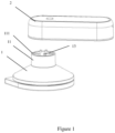
Figure 1 is a schematic view showing a wireless handheld device. -
Figure 2 is a sectional view showing the wireless handheld device. -
Figure 3 is an exploded view showing a device structure of the wireless handheld device. -
Figure 4 is a schematic view showing the wireless handheld device. -
Figure 5 is an exploded view showing a handle of the wireless handheld device. -
Figure 6 is a schematic view showing a handle of the wireless handheld device. -
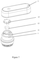
Figure 7 is a schematic view showing an electric hair brush of the wireless handheld device. -
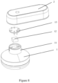
Figure 8 is a schematic view showing a lint ball trimmer of the wireless handheld device. -
Figure 9 is a schematic exploded view showing a wireless handheld device. -
Figure 10 is a schematic view showing the wireless handheld device -
Figure 11 is a sectional view showing the wireless handheld device. - In the drawings: 1. Device structure, 11. Connector, 111. Positioning groove, 12. Second magnetic structure, 13. First contact, 2. Handle, 21. Slot, 211. Positioning rib, 22. First magnetic structure, 23. Second contact, 30. Top cover, 31. Middle cover, 311. Fin, 32. Pressing plate, 33. Ceramic heating piece, 34. Bottom plate, 40. Upper shell, 41. Lower shell, 42. Electronic board, 43. Display screen, 44. Charging interface, 45. USB output interface; 5. Bottom plate sleeve, 6. Slot, 61. First clamping block, 7. Connector, 71. Second clamping block.
- Like reference numerals refer to like elements throughout.
- The terminology used herein is for the purpose of describing particular embodiments only and is not intended to be limiting of the invention. As used herein, the singular forms "a", "an" and "the" are intended to include the plural forms as well, unless the context clearly indicates otherwise. It will be further understood that the terms "comprises" and/or "comprising," or "includes" and/or "including" or "has" and/or "having" when used herein, specify the presence of stated features, regions, integers, steps, operations, elements, and/or components, but do not preclude the presence or addition of one or more other features, regions, integers, steps, operations, elements, components, and/or groups thereof.
- Unless otherwise defined, all terms (including technical and scientific terms) used herein have the same meaning as commonly understood by one of ordinary skill in the art to which this invention belongs. It will be further understood that terms, such as those defined in commonly used dictionaries, should be interpreted as having a meaning that is consistent with their meaning in the context of the relevant art and the present disclosure, and will not be interpreted in an idealized or overly formal sense unless expressly so defined herein.
- As used herein, "around", "about" or "approximately" shall generally mean within 20 percent, preferably within 10 percent, and more preferably within 5 percent of a given value or range. Numerical quantities given herein are approximate, meaning that the term "around", "about" or "approximately" can be inferred if not expressly stated.
- As used herein, the term "plurality" means a number greater than one.
- Hereinafter, certain exemplary embodiments according to the present disclosure will be described with reference to the accompanying drawings.
-
-
Figure 1 is a schematic view showing a wireless handheld device. -
Figure 2 is a sectional view showing the wireless handheld device. -
Figure 3 is an exploded view showing a device structure of the wireless handheld device. -
Figure 4 is a schematic view showing the wireless handheld device. -
Figure 5 is an exploded view showing a handle of the wireless handheld device. -
Figure 6 is a schematic view showing a handle of the wireless handheld device. -
Figure 7 is a schematic view showing an electric hair brush of the wireless handheld device. -
Figure 8 is a schematic view showing a lint ball trimmer of the wireless handheld device. - With reference to
Figures 1 to 8 , a wireless handheld device is shown which comprises adevice structure 1 and ahandle 2, wherein thedevice structure 1 is detachably connected to thehandle 2 by a magnetic type structure; a lithium battery is disposed in thehandle 2; and a driving mechanism is disposed in thedevice structure 1. - Furthermore, the magnetic type structure comprises a
slot 21 and aconnector 11, wherein theslot 21 is fitted with theconnector 11; theslot 21 is arranged on a lower surface of thehandle 2; theconnector 11 is arranged on an upper surface of thedevice structure 1; a firstmagnetic structure 22 is disposed in theslot 21; a secondmagnetic structure 12 is disposed in theconnector 11; and the firstmagnetic structure 22 matches with the secondmagnetic structure 12. - Preferably, both the first
magnetic structure 22 and the secondmagnetic structure 12 are iron sheets, or the firstmagnetic structure 22 is an iron sheet and the secondmagnetic structure 12 is a magnet, or both the firstmagnetic structure 22 and the secondmagnetic structure 12 are magnets. The firstmagnetic structure 22 and the secondmagnetic structure 12 provide a detachable connection which is achieved by magnetic attraction, so as to facilitate the disassembly and storage of wireless iron devices. Preferably, the magnet and the iron sheet are of rectangular shapes for alignment of magnetic attraction. - Furthermore, the magnetic type structure further comprises a plurality of
first contacts 13 and a plurality ofsecond contacts 23, wherein each of the plurality offirst contacts 13 matches with each of the plurality ofsecond contacts 23; the plurality offirst contacts 13 are electrically connected to the driving mechanism and the plurality ofsecond contacts 23 are electrically connected to the lithium battery; and each of the plurality offirst contacts 13 is detachably electrically connected to each of the plurality ofsecond contacts 23. The plurality offirst contacts 13 and the plurality ofsecond contacts 23 provide means for connection of circuit, allowing the ceramic heating piece 33 to be electrically conducted via the first contacts to enter the operating state. Preferably, the number of the plurality of first contacts is 4. - Furthermore, the
device structure 1 is an electric iron, and the driving mechanism is a heating structure. - Furthermore, the heating structure comprises, as fixably disposed parts in a sequence from top to bottom, a
top cover 30, amiddle cover 31, a pressing plate 32, a ceramic heating piece 33, and abottom plate 34, wherein thetop cover 30 is of a conical shape; an upper end of thetop cover 30 extends upward to form theconnector 11; a periphery of the pressing plate 32 is fixedly connected to thebottom plate 34; a lower surface of the pressing plate 32 rests against the ceramic heating piece 33; and a lower surface of the ceramic heating piece 33 rests against thebottom plate 34. A lower surface of thebottom plate 34 is of a teardrop shape. A periphery of the teardrop-shaped structure of thebottom plate 34 comprises a sharp-angled portion on the left side ofFigure 3 and a circular arc portion on the right side ofFigure 3 , wherein the sharp-angled portion is particularly suitable for ironing some clothes, such as shirts and trousers having folds. - Furthermore, the
bottom plate 34 is provided with a bottom plate groove, and both the ceramic heating piece 33 and thepressing plate 34 are disposed in the bottom plate groove. - An upper surface of the
middle cover 31 is further provided with a plurality offins 311, and the plurality offins 311 are arranged in a circumferential array. - The
device structure 1 may be an electric lint ball trimmer shown inFigure 8 or an electric hair brush shown inFigure 7 . The electric iron, the electric lint ball trimmer or the electric hair brush may be connected with or detached from thehandle 2 by a quick rotation, insertion or disconnection for switching functions as desired. - The
handle 2 comprises anupper shell 40 and alower shell 41, wherein theupper shell 40 is fixedly connected to thelower shell 41; anelectronic board 42 is arranged inside theupper shell 40 and thelower shell 41; the plurality ofsecond contacts 23, adisplay screen 43 and the lithium battery are disposed on theelectronic board 42; one side of a lower surface of thelower shell 41 is provided with aslot 21 in which the plurality ofsecond contacts 23 are located. - The
electronic board 42 is further provided with a charginginterface 44 and aUSB output interface 45. The presence of theUSB output interface 45 makes it possible for thehandle 2 to serve as power bank (i.e., a portable charger) when it is not used with the heating structure. - Side walls of the
slot 21 have a plurality of positioning ribs, side surfaces of theconnector 11 have a plurality ofpositioning grooves 111, and each of the positioning ribs 211is fitted with each of thepositioning grooves 111. - The plurality of
positioning grooves 111 extend from an upper end of theconnector 11 to a middle portion of theconnector 11. - The handheld device, further comprises: a
bottom plate sleeve 5 having a teardrop shape fitted to the shape of thebottom plate 34. Thebottom plate sleeve 5 is made of high-temperature resistant silicone material. When the device is stored, thebottom plate sleeve 5 functions as a storage component for thebottom plate 34. Referring toFigure 5 , when in regular use, thebottom plate sleeve 5 functions as an iron stand for shelving the iron in the case of the non-use of the iron, such that a table top or the clothes may not be burnt and damaged. - Example 2 not being part of the invention, presented for illustrative purpose.
-
Figure 9 is a schematic exploded view showing a wireless handheld device.Figure 10 is a schematic view showing the wireless handheld device.Figure 11 is a sectional view showing the wireless handheld device. With reference toFigures 9 to 11 , a wireless handheld is shown. - The clamping type structure comprises a
slot 6 and aconnector 7, wherein theslot 6 is fitted with theconnector 7; theslot 6 is arranged on a lower surface of thehandle 2; theconnector 7 is arranged on an upper surface of thedevice structure 1; a lower end of theslot 6 extends inward to form afirst clamping block 61, an upper end of theconnector 7 extends outward to form asecond clamping block 71; theslot 6 and theconnector 7 are rotated and connected by thefirst clamping block 61 and thesecond clamping block 71. Thedevice structure 1 is rotated in one direction such that thesecond clamping block 71 is positioned in a gap between two first clamping blocks 61, and theconnector 7 is then inserted into theslot 6; afterwards, thedevice structure 1 is rotated in an opposite direction such that thesecond clamping block 71 is positioned above thefirst clamping block 61. Thus, thedevice structure 1 is fixedly connected with thehandle 2. - The clamping type structure further comprises a plurality of
first contacts 13 and a plurality ofsecond contacts 23, wherein each of the plurality offirst contacts 13 matches with each of the plurality ofsecond contacts 23; the plurality offirst contacts 13 are electrically connected to the driving mechanism and the plurality ofsecond contacts 23 are electrically connected to the lithium battery; and each of the plurality offirst contacts 13 is detachably electrically connected to each of the plurality ofsecond contacts 23.
Claims (7)
- A wireless handheld device, comprising:a device structure (1) and a handle (2), the device structure (1) being connected to the handle (2) by a detachable structure, a lithium battery being disposed in the handle (2), a driving mechanism being disposed in the device structure (1);the detachable structure is a magnetic type structure;wherein the detachable structure comprises a slot (21), a connector (11), a plurality of first contacts (13) and a plurality of second contacts (23), the slot (21) is fitted with the connector (11), the slot (21) is arranged on a lower surface of the handle (2), the connector (11) is arranged on an upper surface of the device structure (1), wherein each of the plurality of first contacts (13) matches with each of the plurality of second contacts (23), the plurality of first contacts (13) are electrically connected to the driving mechanism and the plurality of second contacts (23) are electrically connected to the lithium battery, and each of the plurality of first contacts (13) is detachably electrically connected to each of the plurality of second contacts (23);wherein, a first magnetic structure (22) is disposed in the slot (21), a second magnetic structure (12) is disposed in the connector (11), and the first magnetic structure (22) matches with the second magnetic structure (12);wherein the device structure (1) is an electric iron, and the driving mechanism is a heating structure;wherein the heating structure comprises, as fixably disposed parts in a sequence from top to bottom, a top cover (30), a middle cover (31), a pressing plate (32), a ceramic heating piece (33), and a bottom plate (34), wherein the top cover (30) is of a conical shape; an upper end of the top cover (30) extends upward to form the connector (11); a periphery of the pressing plate (32) is fixedly connected to the bottom plate (34); a lower surface of the pressing plate (32) rests against the ceramic heating piece (33); and a lower surface of the ceramic heating piece (33) rests against the bottom plate (34);wherein the bottom plate (34) is provided with a bottom plate groove, and both the ceramic heating piece (33) and the pressing plate (32) are disposed in the bottom plate groove.
- The wireless handheld device of claim 1, wherein an upper surface of the middle cover (31) is further provided with a plurality of fins (311), and the plurality of fins (311) are arranged in a circumferential array.
- The wireless handheld device of claim 1, wherein the handle comprises an upper shell (40) and a lower shell (41), wherein the upper shell (40) is fixedly connected to the lower shell (41); an electronic board (42) is arranged inside the upper shell (40) and the lower shell (41); the plurality of second contacts (23), a display screen (43) and the lithium battery are disposed on the electronic board (42); one side of a lower surface of the lower shell (41) is provided with a slot (21) in which the plurality of second contacts (23) are located.
- The wireless handheld device of claim 3, wherein the electronic board (42) is further provided with a charging interface (44) and a USB output interface (45).
- The wireless handheld device of claim 1, wherein side walls of the slot (21) have a plurality of positioning ribs (211), side surfaces of the connector (11) have a plurality of positioning grooves (111), and each of the positioning ribs (211) is fitted with each of the positioning grooves (111).
- The wireless handheld device of claim 5, wherein the plurality of positioning grooves (111) extend from an upper end of the connector (11) to a middle portion of the connector (11).
- The wireless handheld device of claim 1, further comprising: a bottom plate sleeve (5) having a teardrop shape fitted to the shape of the bottom plate (34).
Applications Claiming Priority (6)
| Application Number | Priority Date | Filing Date | Title |
|---|---|---|---|
| CN201920217977.7U CN209907071U (en) | 2019-02-19 | 2019-02-19 | Iron with protective sleeve |
| CN201920210297.2U CN209759857U (en) | 2019-02-19 | 2019-02-19 | take flatiron of emergent function |
| CN201920888552.9U CN210506910U (en) | 2019-06-13 | 2019-06-13 | A handle of a new type of wireless ironing equipment |
| CN201920888534.0U CN210506909U (en) | 2019-06-13 | 2019-06-13 | Heating structure of a new type of wireless ironing equipment |
| CN201910512685.0A CN110176693A (en) | 2019-06-13 | 2019-06-13 | A kind of connection structure of novel hand-held equipment |
| CN201910512683.1A CN110130082A (en) | 2019-06-13 | 2019-06-13 | A kind of novel radio ironing class equipment |
Publications (3)
| Publication Number | Publication Date |
|---|---|
| EP3699350A1 EP3699350A1 (en) | 2020-08-26 |
| EP3699350B1 true EP3699350B1 (en) | 2025-05-21 |
| EP3699350C0 EP3699350C0 (en) | 2025-05-21 |
Family
ID=68426341
Family Applications (1)
| Application Number | Title | Priority Date | Filing Date |
|---|---|---|---|
| EP19206970.6A Active EP3699350B1 (en) | 2019-02-19 | 2019-11-04 | Wireless handheld device |
Country Status (4)
| Country | Link |
|---|---|
| US (1) | US11545837B2 (en) |
| EP (1) | EP3699350B1 (en) |
| JP (1) | JP6888066B2 (en) |
| KR (1) | KR102625919B1 (en) |
Families Citing this family (3)
| Publication number | Priority date | Publication date | Assignee | Title |
|---|---|---|---|---|
| CN113769131A (en) * | 2021-09-30 | 2021-12-10 | 华引芯(武汉)科技有限公司 | Handheld sterilizing device |
| US20250230604A1 (en) * | 2024-01-15 | 2025-07-17 | Hcl Technologies Limited | Multipurpose garment care device |
| CN119411364A (en) * | 2025-01-06 | 2025-02-11 | 宁波爱佳电器有限公司 | Combined accessories for steam ironing equipment and steam ironing equipment |
Family Cites Families (20)
| Publication number | Priority date | Publication date | Assignee | Title |
|---|---|---|---|---|
| US974137A (en) * | 1909-09-22 | 1910-11-01 | Sarah A Haring | Flat-iron heater. |
| JPS447913Y1 (en) * | 1965-01-23 | 1969-03-26 | ||
| US3533119A (en) * | 1968-03-06 | 1970-10-13 | Sunbeam Corp | Cordless portable electric appliance |
| US4050003A (en) * | 1974-08-23 | 1977-09-20 | The Black And Decker Manufacturing Company | Modular cordless tools |
| JPS6016278B2 (en) * | 1980-01-21 | 1985-04-24 | テ−ルソン | Fabric wrinkle removal device |
| JPS58115200U (en) * | 1982-01-30 | 1983-08-06 | 松下電工株式会社 | iron |
| JPS6321100A (en) * | 1986-07-15 | 1988-01-28 | 東芝ホームテクノ株式会社 | Iron |
| JPH0233296U (en) * | 1988-08-25 | 1990-03-01 | ||
| JPH07116026A (en) * | 1993-10-26 | 1995-05-09 | Meito:Kk | Brush attachment for hair |
| CA2576509A1 (en) * | 2004-08-10 | 2006-03-02 | Powerpulse Technologies, L.P. | Portable energy consuming device |
| GB2422047B (en) * | 2005-01-10 | 2007-07-18 | Nanjing Chervon Ind Co Ltd | Power tool with battery power supply |
| CN2762964Y (en) * | 2005-01-10 | 2006-03-08 | 南京德朔实业有限公司 | Electric tool power supplied by battery |
| TW200831034A (en) * | 2007-01-17 | 2008-08-01 | Tsann Kuen Entpr Co Ltd | Electrical iron |
| JP6475972B2 (en) * | 2014-12-19 | 2019-02-27 | ツインバード工業株式会社 | Steam iron |
| CN110268191A (en) * | 2016-11-04 | 2019-09-20 | 卢米内德实验室有限责任公司 | Multi-Powered Solar Lighting |
| US20180313025A1 (en) * | 2017-04-26 | 2018-11-01 | Farhad Moalem | Cordless steam iron system |
| KR102076714B1 (en) * | 2018-05-02 | 2020-02-12 | (주)오앤케이테크 | Ceramic heating element composition and Ceramic heating element |
| CN108708154B (en) | 2018-06-13 | 2020-07-03 | 广东美的环境电器制造有限公司 | Electric iron |
| CN108914520B (en) | 2018-07-17 | 2020-12-08 | 宁波市聚梦智能科技有限公司 | Electric iron |
| CN109162077A (en) | 2018-09-25 | 2019-01-08 | 何永 | intelligent electric iron |
-
2019
- 2019-10-28 KR KR1020190134379A patent/KR102625919B1/en active Active
- 2019-10-30 JP JP2019197428A patent/JP6888066B2/en active Active
- 2019-10-30 US US16/668,270 patent/US11545837B2/en active Active
- 2019-11-04 EP EP19206970.6A patent/EP3699350B1/en active Active
Also Published As
| Publication number | Publication date |
|---|---|
| JP2020131011A (en) | 2020-08-31 |
| US20200266646A1 (en) | 2020-08-20 |
| KR102625919B1 (en) | 2024-01-16 |
| EP3699350C0 (en) | 2025-05-21 |
| KR20200101822A (en) | 2020-08-28 |
| JP6888066B2 (en) | 2021-06-16 |
| US11545837B2 (en) | 2023-01-03 |
| EP3699350A1 (en) | 2020-08-26 |
Similar Documents
| Publication | Publication Date | Title |
|---|---|---|
| EP3699350B1 (en) | Wireless handheld device | |
| US3710224A (en) | Display stand for rechargeable battery operated appliance | |
| JP2017519348A (en) | Battery with USB terminal | |
| US10145060B1 (en) | Portable rechargeable iron | |
| CN110130082A (en) | A kind of novel radio ironing class equipment | |
| CN223023681U (en) | An integrated AC charging and discharging gun | |
| JP2010178516A (en) | Plug-in battery charger | |
| CN211171325U (en) | Handle of ironing device | |
| CN214362392U (en) | Hand-held garment steamer | |
| CN212395470U (en) | Champignon machine | |
| TWI727682B (en) | Wireless handheld device | |
| CN110176693A (en) | A kind of connection structure of novel hand-held equipment | |
| CN222256709U (en) | Portable lithium electric stove | |
| CN207691538U (en) | A kind of game paddle | |
| CN222397391U (en) | Wireless blower | |
| CN211320977U (en) | A detachable electric iron | |
| CN212834667U (en) | Mini wireless electric iron | |
| CN215070543U (en) | Shell of power adapter plug and power adapter plug with shell | |
| CN220253386U (en) | Battery unit and small household appliance | |
| CN211284978U (en) | Wireless electric iron with mobile power supply | |
| CN215077677U (en) | Frying and baking machine convenient to operate | |
| CN202830590U (en) | Iron | |
| CN210506909U (en) | Heating structure of a new type of wireless ironing equipment | |
| CN212771612U (en) | Wireless charging iron | |
| CN213114012U (en) | Detachable connecting device of wireless electric iron |
Legal Events
| Date | Code | Title | Description |
|---|---|---|---|
| PUAI | Public reference made under article 153(3) epc to a published international application that has entered the european phase |
Free format text: ORIGINAL CODE: 0009012 |
|
| STAA | Information on the status of an ep patent application or granted ep patent |
Free format text: STATUS: THE APPLICATION HAS BEEN PUBLISHED |
|
| AK | Designated contracting states |
Kind code of ref document: A1 Designated state(s): AL AT BE BG CH CY CZ DE DK EE ES FI FR GB GR HR HU IE IS IT LI LT LU LV MC MK MT NL NO PL PT RO RS SE SI SK SM TR |
|
| AX | Request for extension of the european patent |
Extension state: BA ME |
|
| RIN1 | Information on inventor provided before grant (corrected) |
Inventor name: LI, YONGBO |
|
| STAA | Information on the status of an ep patent application or granted ep patent |
Free format text: STATUS: REQUEST FOR EXAMINATION WAS MADE |
|
| 17P | Request for examination filed |
Effective date: 20210201 |
|
| RBV | Designated contracting states (corrected) |
Designated state(s): AL AT BE BG CH CY CZ DE DK EE ES FI FR GB GR HR HU IE IS IT LI LT LU LV MC MK MT NL NO PL PT RO RS SE SI SK SM TR |
|
| STAA | Information on the status of an ep patent application or granted ep patent |
Free format text: STATUS: EXAMINATION IS IN PROGRESS |
|
| 17Q | First examination report despatched |
Effective date: 20230504 |
|
| GRAP | Despatch of communication of intention to grant a patent |
Free format text: ORIGINAL CODE: EPIDOSNIGR1 |
|
| STAA | Information on the status of an ep patent application or granted ep patent |
Free format text: STATUS: GRANT OF PATENT IS INTENDED |
|
| INTG | Intention to grant announced |
Effective date: 20241022 |
|
| GRAJ | Information related to disapproval of communication of intention to grant by the applicant or resumption of examination proceedings by the epo deleted |
Free format text: ORIGINAL CODE: EPIDOSDIGR1 |
|
| STAA | Information on the status of an ep patent application or granted ep patent |
Free format text: STATUS: EXAMINATION IS IN PROGRESS |
|
| INTC | Intention to grant announced (deleted) | ||
| GRAP | Despatch of communication of intention to grant a patent |
Free format text: ORIGINAL CODE: EPIDOSNIGR1 |
|
| STAA | Information on the status of an ep patent application or granted ep patent |
Free format text: STATUS: GRANT OF PATENT IS INTENDED |
|
| INTG | Intention to grant announced |
Effective date: 20250217 |
|
| GRAS | Grant fee paid |
Free format text: ORIGINAL CODE: EPIDOSNIGR3 |
|
| GRAA | (expected) grant |
Free format text: ORIGINAL CODE: 0009210 |
|
| STAA | Information on the status of an ep patent application or granted ep patent |
Free format text: STATUS: THE PATENT HAS BEEN GRANTED |
|
| AK | Designated contracting states |
Kind code of ref document: B1 Designated state(s): AL AT BE BG CH CY CZ DE DK EE ES FI FR GB GR HR HU IE IS IT LI LT LU LV MC MK MT NL NO PL PT RO RS SE SI SK SM TR |
|
| REG | Reference to a national code |
Ref country code: GB Ref legal event code: FG4D |
|
| REG | Reference to a national code |
Ref country code: CH Ref legal event code: EP |
|
| REG | Reference to a national code |
Ref country code: DE Ref legal event code: R096 Ref document number: 602019070183 Country of ref document: DE |
|
| REG | Reference to a national code |
Ref country code: IE Ref legal event code: FG4D |
|
| U01 | Request for unitary effect filed |
Effective date: 20250612 |
|
| U07 | Unitary effect registered |
Designated state(s): AT BE BG DE DK EE FI FR IT LT LU LV MT NL PT RO SE SI Effective date: 20250624 |
|
| PG25 | Lapsed in a contracting state [announced via postgrant information from national office to epo] |
Ref country code: ES Free format text: LAPSE BECAUSE OF FAILURE TO SUBMIT A TRANSLATION OF THE DESCRIPTION OR TO PAY THE FEE WITHIN THE PRESCRIBED TIME-LIMIT Effective date: 20250521 |
|
| PG25 | Lapsed in a contracting state [announced via postgrant information from national office to epo] |
Ref country code: NO Free format text: LAPSE BECAUSE OF FAILURE TO SUBMIT A TRANSLATION OF THE DESCRIPTION OR TO PAY THE FEE WITHIN THE PRESCRIBED TIME-LIMIT Effective date: 20250821 Ref country code: GR Free format text: LAPSE BECAUSE OF FAILURE TO SUBMIT A TRANSLATION OF THE DESCRIPTION OR TO PAY THE FEE WITHIN THE PRESCRIBED TIME-LIMIT Effective date: 20250822 |
|
| PG25 | Lapsed in a contracting state [announced via postgrant information from national office to epo] |
Ref country code: PL Free format text: LAPSE BECAUSE OF FAILURE TO SUBMIT A TRANSLATION OF THE DESCRIPTION OR TO PAY THE FEE WITHIN THE PRESCRIBED TIME-LIMIT Effective date: 20250521 |
|
| PG25 | Lapsed in a contracting state [announced via postgrant information from national office to epo] |
Ref country code: HR Free format text: LAPSE BECAUSE OF FAILURE TO SUBMIT A TRANSLATION OF THE DESCRIPTION OR TO PAY THE FEE WITHIN THE PRESCRIBED TIME-LIMIT Effective date: 20250521 |
|
| PG25 | Lapsed in a contracting state [announced via postgrant information from national office to epo] |
Ref country code: RS Free format text: LAPSE BECAUSE OF FAILURE TO SUBMIT A TRANSLATION OF THE DESCRIPTION OR TO PAY THE FEE WITHIN THE PRESCRIBED TIME-LIMIT Effective date: 20250821 |
|
| PG25 | Lapsed in a contracting state [announced via postgrant information from national office to epo] |
Ref country code: IS Free format text: LAPSE BECAUSE OF FAILURE TO SUBMIT A TRANSLATION OF THE DESCRIPTION OR TO PAY THE FEE WITHIN THE PRESCRIBED TIME-LIMIT Effective date: 20250921 |
|
| U20 | Renewal fee for the european patent with unitary effect paid |
Year of fee payment: 7 Effective date: 20251003 |
|
| PG25 | Lapsed in a contracting state [announced via postgrant information from national office to epo] |
Ref country code: SM Free format text: LAPSE BECAUSE OF FAILURE TO SUBMIT A TRANSLATION OF THE DESCRIPTION OR TO PAY THE FEE WITHIN THE PRESCRIBED TIME-LIMIT Effective date: 20250521 |
|
| PG25 | Lapsed in a contracting state [announced via postgrant information from national office to epo] |
Ref country code: CZ Free format text: LAPSE BECAUSE OF FAILURE TO SUBMIT A TRANSLATION OF THE DESCRIPTION OR TO PAY THE FEE WITHIN THE PRESCRIBED TIME-LIMIT Effective date: 20250521 |
|
| PG25 | Lapsed in a contracting state [announced via postgrant information from national office to epo] |
Ref country code: SK Free format text: LAPSE BECAUSE OF FAILURE TO SUBMIT A TRANSLATION OF THE DESCRIPTION OR TO PAY THE FEE WITHIN THE PRESCRIBED TIME-LIMIT Effective date: 20250521 |
|
| PLBE | No opposition filed within time limit |
Free format text: ORIGINAL CODE: 0009261 |
|
| STAA | Information on the status of an ep patent application or granted ep patent |
Free format text: STATUS: NO OPPOSITION FILED WITHIN TIME LIMIT |
|
| REG | Reference to a national code |
Ref country code: CH Ref legal event code: L10 Free format text: ST27 STATUS EVENT CODE: U-0-0-L10-L00 (AS PROVIDED BY THE NATIONAL OFFICE) Effective date: 20260402 |
|
| 26N | No opposition filed |
Effective date: 20260224 |