EP3698995A1 - Vtol fixed-wing flying platform system - Google Patents
Vtol fixed-wing flying platform system Download PDFInfo
- Publication number
- EP3698995A1 EP3698995A1 EP20158443.0A EP20158443A EP3698995A1 EP 3698995 A1 EP3698995 A1 EP 3698995A1 EP 20158443 A EP20158443 A EP 20158443A EP 3698995 A1 EP3698995 A1 EP 3698995A1
- Authority
- EP
- European Patent Office
- Prior art keywords
- cabin
- flying platform
- recited
- disposed
- propeller
- Prior art date
- Legal status (The legal status is an assumption and is not a legal conclusion. Google has not performed a legal analysis and makes no representation as to the accuracy of the status listed.)
- Granted
Links
Images










Classifications
-
- B—PERFORMING OPERATIONS; TRANSPORTING
- B64—AIRCRAFT; AVIATION; COSMONAUTICS
- B64C—AEROPLANES; HELICOPTERS
- B64C29/00—Aircraft capable of landing or taking-off vertically, e.g. vertical take-off and landing [VTOL] aircraft
-
- B—PERFORMING OPERATIONS; TRANSPORTING
- B64—AIRCRAFT; AVIATION; COSMONAUTICS
- B64C—AEROPLANES; HELICOPTERS
- B64C37/00—Convertible aircraft
-
- B—PERFORMING OPERATIONS; TRANSPORTING
- B60—VEHICLES IN GENERAL
- B60F—VEHICLES FOR USE BOTH ON RAIL AND ON ROAD; VEHICLES CAPABLE OF TRAVELLING IN OR ON DIFFERENT MEDIA, e.g. AMPHIBIOUS VEHICLES
- B60F5/00—Other vehicles capable of travelling in or on different media
-
- B—PERFORMING OPERATIONS; TRANSPORTING
- B64—AIRCRAFT; AVIATION; COSMONAUTICS
- B64C—AEROPLANES; HELICOPTERS
- B64C25/00—Alighting gear
- B64C25/32—Alighting gear characterised by elements which contact the ground or similar surface
- B64C25/54—Floats
-
- B—PERFORMING OPERATIONS; TRANSPORTING
- B64—AIRCRAFT; AVIATION; COSMONAUTICS
- B64C—AEROPLANES; HELICOPTERS
- B64C25/00—Alighting gear
- B64C25/32—Alighting gear characterised by elements which contact the ground or similar surface
- B64C25/54—Floats
- B64C25/56—Floats inflatable
-
- B—PERFORMING OPERATIONS; TRANSPORTING
- B64—AIRCRAFT; AVIATION; COSMONAUTICS
- B64C—AEROPLANES; HELICOPTERS
- B64C27/00—Rotorcraft; Rotors peculiar thereto
- B64C27/22—Compound rotorcraft, i.e. aircraft using in flight the features of both aeroplane and rotorcraft
-
- B—PERFORMING OPERATIONS; TRANSPORTING
- B64—AIRCRAFT; AVIATION; COSMONAUTICS
- B64C—AEROPLANES; HELICOPTERS
- B64C27/00—Rotorcraft; Rotors peculiar thereto
- B64C27/22—Compound rotorcraft, i.e. aircraft using in flight the features of both aeroplane and rotorcraft
- B64C27/26—Compound rotorcraft, i.e. aircraft using in flight the features of both aeroplane and rotorcraft characterised by provision of fixed wings
-
- B—PERFORMING OPERATIONS; TRANSPORTING
- B64—AIRCRAFT; AVIATION; COSMONAUTICS
- B64C—AEROPLANES; HELICOPTERS
- B64C29/00—Aircraft capable of landing or taking-off vertically, e.g. vertical take-off and landing [VTOL] aircraft
- B64C29/0008—Aircraft capable of landing or taking-off vertically, e.g. vertical take-off and landing [VTOL] aircraft having its flight directional axis horizontal when grounded
- B64C29/0016—Aircraft capable of landing or taking-off vertically, e.g. vertical take-off and landing [VTOL] aircraft having its flight directional axis horizontal when grounded the lift during taking-off being created by free or ducted propellers or by blowers
- B64C29/0025—Aircraft capable of landing or taking-off vertically, e.g. vertical take-off and landing [VTOL] aircraft having its flight directional axis horizontal when grounded the lift during taking-off being created by free or ducted propellers or by blowers the propellers being fixed relative to the fuselage
-
- B—PERFORMING OPERATIONS; TRANSPORTING
- B64—AIRCRAFT; AVIATION; COSMONAUTICS
- B64C—AEROPLANES; HELICOPTERS
- B64C35/00—Flying-boats; Seaplanes
- B64C35/005—Flying-boats; Seaplanes with propellers, rudders or brakes acting in the water
-
- B—PERFORMING OPERATIONS; TRANSPORTING
- B64—AIRCRAFT; AVIATION; COSMONAUTICS
- B64C—AEROPLANES; HELICOPTERS
- B64C37/00—Convertible aircraft
- B64C37/02—Flying units formed by separate aircraft
-
- B—PERFORMING OPERATIONS; TRANSPORTING
- B64—AIRCRAFT; AVIATION; COSMONAUTICS
- B64C—AEROPLANES; HELICOPTERS
- B64C39/00—Aircraft not otherwise provided for
- B64C39/04—Aircraft not otherwise provided for having multiple fuselages or tail booms
-
- B—PERFORMING OPERATIONS; TRANSPORTING
- B64—AIRCRAFT; AVIATION; COSMONAUTICS
- B64C—AEROPLANES; HELICOPTERS
- B64C39/00—Aircraft not otherwise provided for
- B64C39/06—Aircraft not otherwise provided for having disc- or ring-shaped wings
- B64C39/068—Aircraft not otherwise provided for having disc- or ring-shaped wings having multiple wings joined at the tips
-
- B—PERFORMING OPERATIONS; TRANSPORTING
- B64—AIRCRAFT; AVIATION; COSMONAUTICS
- B64C—AEROPLANES; HELICOPTERS
- B64C39/00—Aircraft not otherwise provided for
- B64C39/12—Canard-type aircraft
-
- B—PERFORMING OPERATIONS; TRANSPORTING
- B64—AIRCRAFT; AVIATION; COSMONAUTICS
- B64D—EQUIPMENT FOR FITTING IN OR TO AIRCRAFT; FLIGHT SUITS; PARACHUTES; ARRANGEMENT OR MOUNTING OF POWER PLANTS OR PROPULSION TRANSMISSIONS IN AIRCRAFT
- B64D9/00—Equipment for handling freight; Equipment for facilitating passenger embarkation or the like
-
- B—PERFORMING OPERATIONS; TRANSPORTING
- B64—AIRCRAFT; AVIATION; COSMONAUTICS
- B64U—UNMANNED AERIAL VEHICLES [UAV]; EQUIPMENT THEREFOR
- B64U10/00—Type of UAV
- B64U10/20—Vertical take-off and landing [VTOL] aircraft
-
- B—PERFORMING OPERATIONS; TRANSPORTING
- B64—AIRCRAFT; AVIATION; COSMONAUTICS
- B64U—UNMANNED AERIAL VEHICLES [UAV]; EQUIPMENT THEREFOR
- B64U10/00—Type of UAV
- B64U10/70—Convertible aircraft, e.g. convertible into land vehicles
-
- B—PERFORMING OPERATIONS; TRANSPORTING
- B64—AIRCRAFT; AVIATION; COSMONAUTICS
- B64U—UNMANNED AERIAL VEHICLES [UAV]; EQUIPMENT THEREFOR
- B64U30/00—Means for producing lift; Empennages; Arrangements thereof
- B64U30/10—Wings
-
- B—PERFORMING OPERATIONS; TRANSPORTING
- B64—AIRCRAFT; AVIATION; COSMONAUTICS
- B64U—UNMANNED AERIAL VEHICLES [UAV]; EQUIPMENT THEREFOR
- B64U50/00—Propulsion; Power supply
- B64U50/10—Propulsion
- B64U50/19—Propulsion using electrically powered motors
-
- B—PERFORMING OPERATIONS; TRANSPORTING
- B60—VEHICLES IN GENERAL
- B60F—VEHICLES FOR USE BOTH ON RAIL AND ON ROAD; VEHICLES CAPABLE OF TRAVELLING IN OR ON DIFFERENT MEDIA, e.g. AMPHIBIOUS VEHICLES
- B60F5/00—Other vehicles capable of travelling in or on different media
- B60F5/02—Other vehicles capable of travelling in or on different media convertible into aircraft
-
- B—PERFORMING OPERATIONS; TRANSPORTING
- B63—SHIPS OR OTHER WATERBORNE VESSELS; RELATED EQUIPMENT
- B63B—SHIPS OR OTHER WATERBORNE VESSELS; EQUIPMENT FOR SHIPPING
- B63B7/00—Collapsible, foldable, inflatable or like vessels
- B63B7/06—Collapsible, foldable, inflatable or like vessels having parts of non-rigid material
- B63B7/08—Inflatable
-
- B—PERFORMING OPERATIONS; TRANSPORTING
- B64—AIRCRAFT; AVIATION; COSMONAUTICS
- B64C—AEROPLANES; HELICOPTERS
- B64C2211/00—Modular constructions of airplanes or helicopters
-
- B—PERFORMING OPERATIONS; TRANSPORTING
- B64—AIRCRAFT; AVIATION; COSMONAUTICS
- B64D—EQUIPMENT FOR FITTING IN OR TO AIRCRAFT; FLIGHT SUITS; PARACHUTES; ARRANGEMENT OR MOUNTING OF POWER PLANTS OR PROPULSION TRANSMISSIONS IN AIRCRAFT
- B64D25/00—Emergency apparatus or devices, not otherwise provided for
- B64D25/08—Ejecting or escaping means
- B64D25/18—Flotation gear
-
- B—PERFORMING OPERATIONS; TRANSPORTING
- B64—AIRCRAFT; AVIATION; COSMONAUTICS
- B64U—UNMANNED AERIAL VEHICLES [UAV]; EQUIPMENT THEREFOR
- B64U2101/00—UAVs specially adapted for particular uses or applications
- B64U2101/60—UAVs specially adapted for particular uses or applications for transporting passengers; for transporting goods other than weapons
-
- B—PERFORMING OPERATIONS; TRANSPORTING
- B64—AIRCRAFT; AVIATION; COSMONAUTICS
- B64U—UNMANNED AERIAL VEHICLES [UAV]; EQUIPMENT THEREFOR
- B64U30/00—Means for producing lift; Empennages; Arrangements thereof
- B64U30/20—Rotors; Rotor supports
- B64U30/29—Constructional aspects of rotors or rotor supports; Arrangements thereof
- B64U30/294—Rotors arranged in the UAV body
-
- B—PERFORMING OPERATIONS; TRANSPORTING
- B64—AIRCRAFT; AVIATION; COSMONAUTICS
- B64U—UNMANNED AERIAL VEHICLES [UAV]; EQUIPMENT THEREFOR
- B64U40/00—On-board mechanical arrangements for adjusting control surfaces or rotors; On-board mechanical arrangements for in-flight adjustment of the base configuration
- B64U40/10—On-board mechanical arrangements for adjusting control surfaces or rotors; On-board mechanical arrangements for in-flight adjustment of the base configuration for adjusting control surfaces or rotors
-
- B—PERFORMING OPERATIONS; TRANSPORTING
- B64—AIRCRAFT; AVIATION; COSMONAUTICS
- B64U—UNMANNED AERIAL VEHICLES [UAV]; EQUIPMENT THEREFOR
- B64U50/00—Propulsion; Power supply
- B64U50/10—Propulsion
- B64U50/13—Propulsion using external fans or propellers
-
- B—PERFORMING OPERATIONS; TRANSPORTING
- B64—AIRCRAFT; AVIATION; COSMONAUTICS
- B64U—UNMANNED AERIAL VEHICLES [UAV]; EQUIPMENT THEREFOR
- B64U60/00—Undercarriages
- B64U60/30—Undercarriages detachable from the body
Definitions
- the present disclosure relates to a vertical takeoff and landing (VTOL) aerial drone, and more particularly, a VTOL flying platform having interchangeable and detachable cabins.
- VTOL vertical takeoff and landing
- aerial drones are known to carry people, and some aerial drones are known to carry cargo. Each of these two types of drones has its unique challenges to perform effectively and efficiently.
- VTOL vertical take-off and landing
- aerial drone is contemplated to include interchangeable cabins.
- the aerial drone can have a flying platform.
- the flying platform can have a left main wing and a right main wing.
- the flying platform can have a left canard wing and a right canard wing.
- the flying platform can have a main body disposed between the left main wing and the right main wing.
- the flying platform can have a left linear support connecting the left main wing to the left canard wing, a right linear support connecting the right main wing to the right canard wing.
- the left linear support can have a first, a second, a third lifting propellers
- the right linear support can have a fourth, a fifth, a sixth lifting propellers
- the flying platform can have at least one vertical stabilizer.
- the flying platform can have at least two vertical stabilizers, each of which can be disposed at the rear end of each linear support.
- the flying platform can have at least one pushing propeller.
- the flying platform can have at least two pushing propellers, each of which can be disposed at the rear end of each linear support.
- the flying platform can have at least two pushing propellers, each of which can be disposed on a vertical stabilizer, at various distance from the linear support.
- the aerial drone can have a cargo cabin detachably coupled to the flying platform.
- the aerial drone can have a passenger cabin detachably coupled to the flying platform.
- the aerial drone can interchangeably couple to a cargo cabin and a passenger cabin.
- the flying platform can have an energy storage unit disposed within its main body.
- the flying platform can have a hybrid engine to produce electricity.
- each of the two linear supports can have a total of four lifting propellers attached, wherein at least two lifting propellers are disposed at the same lengthwise location on the same linear support, but on opposite sides (i.e., top side and bottom side) of the linear support.
- the flying platform can have a left wing-tip propeller disposed on the distal end of the left main wing, and a right wing-tip propeller disposed on the distal end of the right main wing,
- the pushing propeller is horizontally located at substantially the same level with the cargo cabin or the passenger cabin.
- the pushing propeller can be coupled to a rear end of the main body and is extended downward via a connector so that the pushing propeller is physically away from the main body and vertically offset from the main body.
- the flying platform can have autonomous flight functions to transport passengers and/or cargo.
- the passenger cabin can include user control interface allowing the passenger to control flight path, regardless of whether or not the aerial drone has autonomous flight capabilities.
- the passenger cabin and/or cargo cabin can be attached to either on the top side of the flying platform, the bottom side of the flying platform, or both.
- the flying platform can have at least one single-blade leaf spring as a landing gear.
- the flying platform can use at least one vertical stabilizer as a landing gear.
- At least one vertical stabilizer can have a landing gear attached to its distal end.
- the flying platform is equipped with motorized wheels such that the flying platform can move about freely on the ground or on the landing pad.
- the passenger cabin and/or the cargo cabin is equipped with motorized wheels such that the cabins can move about freely on the ground or on the landing pad.
- the landing gear can be an inflatable floatation device.
- the present disclosure is directed to an aerial drone that transports goods and people using detachable cabins.
- one embodiment of the aerial drone is one that has an overall flat configuration being attachable to separable passenger and/or cargo cabins.
- This overall flat configuration can be defined as a flying platform, a flying trellis, a flying framework, a flying scaffold, and a flying lattice work.
- this flying platform has a canard design having two main wings and two canard wings.
- Contemplated main wings can each have a wing-tip lifting propellers disposed on the distal tip of each main wing.
- the wing-tip lifting propellers can be located on a vertical stabilizer or a vertical lifter which is located at the distal end of each main wing. In this way, the wing-tip lifting propeller could be somewhat position vertically away from the top surface of the main wing.
- each linear support there can be a foldable leg.
- the foldable leg is retracted into the linear support.
- the foldable leg is extended to act as a landing gear, or to support a landing gear.
- Another aspect of the embodiments is directed to a method of minimizing the weight of an aerial drone by using single-blade leaf spring as a landing gear.
- such single-blade leaf spring can be attached to the distal end of a downward-extending vertical stabilizer, effectively using the downward-extending vertical stabilizer as a support for the landing gear.
- example operations, methods, or processes described herein may include more steps or fewer steps than those described. Further, the steps in such example operations, methods, or processes may be performed in different successions than that described or illustrated in the figures.
- drone is defined as a flying transportation system having at least one propeller as one source of propulsion.
- the term “drone” can include “manned” and “unmanned” flying transportation system.
- a manned drone can mean a flying transportation system that carries human passengers all of who has no control over the drone.
- a manned drone can also mean a flying transportation system that carries human passengers some or one of who has some control over the drone.
- Fig. 1 generally depicts an embodiment of VTOL aerial drone 100 having a canard configuration.
- the drone 100 can have two main wings 104A, 104B, and two canard wings 105A, 105B.
- the two main wings 104A, 104B and the two canard wings 105A, 105B can be attached to a main body 102, wherein the main body can be located alone a center longitudinal line of the drone 100.
- the drone 100 does not have a canard configuration. Instead, the drone 100 can have two main wings and two secondary wings, all of which are coupled together forming a flying platform.
- the left and right linear supports 103A, 103B are contemplated to improve the structural integrity of the drone 100.
- the left and right linear supports 103A and 103B can house driving motors (not shown) that drives each of the lifting propellers 108A, 108B, 108C, 108D, 108E, 108F.
- the left and right linear supports 103A and 103B can also house folding legs 111 each of which is retrievable within the left and right linear supports 103A and 103B.
- left and right linear supports 103A, 103B are attached to the distal ends of left and right canard wings 105A, 105B, respectively. In yet another embodiment, the left and right linear supports 103A, 103B extend beyond the canard wings 105A, 105B.
- the left and right linear supports 103A, 103B are attached to near the mid-section of left and right main wings 104A, 104B, respectively. In yet another embodiment, the left and right linear supports 103A, 103B extend in a rearward direction beyond the main wings 104A, 104B.
- the left linear support 103A is contemplated to be relatively narrow in diameter and may have a plurality of lifting propellers 108A, 108B, 108C disposed on either the top side, bottom side, or both, of the left linear support 103A.
- These lifting propellers 108A, 108B, 108C can be driven by low profile motors disposed within the hollow interior of the left linear support 103A.
- lifting propellers 108A, 108B, 108C are disposed only on the top side of the left linear support 103A.
- the right linear support 103B is contemplated to be relatively narrow in diameter and may have a plurality of lifting propellers 108D, 108E, 108F disposed on either the top side, bottom side, or both, of the right linear support 103B.
- These lifting propellers 108D, 108E, 108F can be driven by low profile motors disposed within the hollow interior of the right linear support. In the embodiment shown in Fig. 1 , lifting propellers 108D, 108E, 108F are disposed only the top side of the right linear support 103B.
- the drone 100 may have at least one pushing propeller to pushing the drone 100 in a forward direction.
- the two pushing propellers 107A, 107B can be disposed, respectively, on the rear distal ends of linear supports 103A, 103B.
- the flying platform 101 can have no pushing propeller.
- the flying platform 101 can attach to a passenger cabin or a cargo cabin that has a pushing propeller disposed thereon.
- Fig. 32 illustrates an embodiment of a passenger cabin having a pushing propeller disposed on its rear end. When this passenger cabin is attached to the flying platform 101 of Fig. 31 , the pushing propeller pushes the flying platform 101 forward.
- each linear support 103A, 103B can be provided two vertical stabilizers 106A, 106B, respectively. While they are shown pointing downwards, there can also be an embodiment where they point upwards.
- each of the main wings 104A, 104B can have an additional lifting propeller 109A, 109B, respectively, disposed at its distal end.
- This can be achieved by providing wing-tip vertical stabilizers 110A, 110B at the distal ends of the main wings 104A, 104B, respectively, and have the lifting propellers 109A, 109B disposed at the upper tip of each wing-tip vertical stabilizers 110A, 110B.
- These wing-tip lifting propellers 109A, 109B can be relatively smaller than the lifting propellers disposed on the linear supports 103A, 103B.
- These wing-tip lifting propellers 109A, 109B can be used to effectively and efficiently control the roll of the drone 100. Being located at a most distal position away from the center axis of the drone 100, these wing-tip lifting propellers 109A, 109B are effective in adjusting the roll of drone 100, and can do so with a diameter smaller than that of other lifting propellers.
- a cabin 130 generally attached under the main body 102 of the drone 100.
- the drone 100 is contemplated to use any type of landing gear.
- the drone 100 can have four single-blade leaf springs 112A, 112B, 112C, 112D as its landing gear.
- the front two single-blade leaf springs 112A, 112C are respectively disposed on the distal ends of folding legs 11IA, 111B. Folding legs 111A, 111B can be respectively retracted into the interior space of the left and right linear supports 103A, 103B during flight.
- the rear two single-blade left springs 112B, 112D are contemplated to be disposed at the bottom distal ends of vertical stabilizers 106A, 106B, respectively.
- the contemplated single-blade leaf springs 112A, 112B, 112C, 112D can be made of suitable materials to provide sufficient resiliency and integrity, such materials include natural and synthetic polymers, various metals and metal alloys, naturally occurring materials, textile fibers, and all reasonable combinations thereof. In one embodiment, carbon fiber is used.
- Fig. 3 shows the cabin as a cargo cabin 130.
- the cargo cabin 130 can have single-blade leaf springs 135A, 135B, 135C, 135D as its landing gear.
- it can have other types of landing gear such as skids, leg stands, and wheels.
- the cargo cabin 130 is detachable from the rest of the drone 100.
- the remaining portion of the drone can be called a flying platform 101.
- the flying platform 101 can fly without carrying a cabin, and it can interchangeably carry different cabins. As will be described later, the flying platform 101 can also carry passenger cabins.
- cabins 130, 140 are carried underneath the flying platform 101.
- Cabins 130, 140 are contemplated to be loaded on the ground, and the loading process can be done prior to or after the flying platform 101 is attached to the cabin 130, 140.
- Fig. 5 shows a top view of the flying platform 101. It can have a generally flat configuration, capable of carrying a load underneath it, or above it. During high speed flying, all six lifting propellers 108A, 108B, 108C, 108D, 108E, 108F can be locked into position so each blade is parallel to the main body 102.
- Fig. 5 shows one embodiment of the flying platform 101 where the canard wings 105A, 105B each has a length no longer than half the length of each of the main wings 104A, 104B.
- Fig. 6 generally depicts the frontal view of the flying platform 101 with a detachably attached cargo cabin 130. Whether it is a cargo cabin 130, passenger cabin 140, or any other types of load, it is especially contemplated that there can be an energy storage unit 150 disposed within the main body 102 of the flying platform.
- the energy stored can be used to power other components of the flying platform, such as the lifting propellers 108A, 108B, 108C, 108D and pushing propellers 107A, 107B.
- the energy stored can be electricity, and the storage unit is a battery. In another embodiment, this energy storage 150 can be used to power accessories within the cabin 130, 140.
- These batteries 150 can also be disposed in other parts of the flying platform 101, such as within the linear supports 103A, 103B.
- an energy storage unit 155 disposed within the cabin 130, 140.
- the energy stored in storage unit 155 can be used to power the lifting propellers 108A, 108B, 108C, 108D and pushing propellers 107A, 107B.
- the energy stored can be electricity, and the storage unit is a battery.
- the flying platform 101 would have replenished energy sources every time the flying platform 101 picks up a new cabin 130, 140.
- the flying platform 101 itself may be emergency energy storage, or a smaller capacity battery 150 necessary to power the flying platform 101 for shorter amount of time while it flies without a cabin 130, 140.
- the main source of electricity for the flying platform 101 comes from battery 150 located in the cabin 130, 140.
- the flying platform 101 swaps an old cabin 130, 140 out for a new cabin 130, 140, the flying platform 101 or the entire VTOL drone system 100 would have a fully charged energy source.
- This is a beneficial method that eliminates the need for a VTOL drone to charge itself.
- the flying platform 101 can work/fly continuously, picking up cargo cabin/passengers cabin, drop off cargo cabin/passengers cabin, for many hours, even days, without the need to stop for charging its battery.
- a passenger cabin 150 is provided.
- This passenger cabin 150 can use any type of landing gear, such as stiff legs 145A, 145B, 145C, 145D as shown.
- Fig. 10 generally depicts one aspect of the disclosure where the cabin (whether cargo cabin or passenger cabin) is detachable.
- passenger cabin 140 can be selectively detached from the flying platform 101.
- the engagement and disengagement between the flying platform 101 and the cabin 140 can be performed autonomously (without simultaneous user intervention) by a computer and/or other sensors and computing devices. Alternatively or optionally, the user can actively control and direct the engagement and disengagement between the flying platform 101 and the cabin 140.
- engaging mechanism 147 can be used to secure the cabin 140 to the flying platform 101.
- the engaging mechanism can be mechanical catches, magnetic catches, tracks and grooves, or a combination of any known engagement means.
- a center pushing propeller 117 coupled to the rear end of the main body 102 (as shown in Fig. 12 ).
- a center pushing propeller 117 is connected to the rear end of the main body 102 via a vertical extender 116.
- the vertical extender 116 can be any structure of any shape to physically couple to pushing propeller 117 such that the center of rotation for the pushing propeller 117 is vertically offset from the main body 102.
- the pushing propeller 117 is vertically offset from the main body 102 such that the center of rotation for the pushing propeller 117 is vertically located at a position to the rear of the cabin 140, or vertically level with the cabin 140. In yet another embodiment, the pushing propeller 117 is vertically level with the top portion of the cabin 140. In still yet another embodiment, the pushing propeller 117 is vertically level with the middle portion of the cabin 140. In a further embodiment, the pushing propeller 117 is vertically level with the bottom portion of the cabin 140.
- each linear support 103A, 103B can contain more than three lifting propellers by providing a longer linear support to contain more lifting propellers, by using smaller diameter lifting propellers, or by placing lifting propellers on both the top side and the bottom side of the linear support.
- Fig. 13 shows one embodiment where two additional lifting propellers 108G, 108H are provided at the bottom front ends of linear support 103A, 103B.
- pushing propellers 107A, 107B has been shown in previous figures to locate at the rear distal ends of the linear supports 103A, 103B, it is specifically contemplated that these pushing propellers 107A, 107B can be disposed at a horizontal level that is lower than the main wings 104A, 104B such as those shown in Fig. 13 . In one aspect, these pushing propellers 107A, 107B can be disposed at a horizontal level substantially equal to the horizontal level of the cabin 130, 140 being carried by the flying platform 101. In another aspect, these pushing propellers 107A, 107B can be disposed about mid-way down the vertical stabilizers 106A, 106B. One contemplated reason to lower the disposition of the pushing propellers 107A, 107B is to minimize a head-dipping effect during flight, which can be caused by aerodynamic effects caused by the cabin 130, 140.
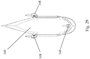
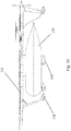
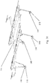
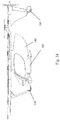
- Figs. 14 to 30 illustrate embodiments where the flying platform 101 or the cabin 130, 140, or both, may each have motorized wheels 148 attached thereon.
- the flying platform 101 has motorized wheels 148; the cabin 130, 140 also has motorized wheels.
- a single unit of motorized wheel 148 can have a motor enclosed in a housing 149, and the motor can be driven by electricity supplied by the energy storage unit 150 disposed in the cabin 130, 140.
- the contemplated motorized wheel 148 can move the flying platform 101 and the cabin 130 across the ground, when they are resting on the ground. This allows a cabin 130, 140 to wheel away from the flying platform 101, and allows another cabin 130, 140 to wheel itself to the flying platform 101 for coupling.
- every cabin 130, 140 can have an energy storage unit 155 so that when the flying platform 101 couples to a new and fully charged cabin 130, 140, the flying platform 101 essentially has replenished its source of energy.
- the contemplate floatation device 160 can be a type that requires actuation, that is, active inflation with gas or upon material when needed.
- the floatation device 160 can remain in a deflated state and is inflated only when certain conditions triggers the inflation.
- the floatation device 160 can be automatically inflated during emergency landing; it can be inflated automatically during water landing; it can be inflated when any of the landing gears malfunction in some ways.
- the contemplated floatation device 160 may be a type that can be reused, re-inflated, re-deflated, over and over.
- the contemplated floatation device 160 can also be of one-time use only.
- the act of inflation can be user activated.
- the operator of the drone system determines a need for inflating the floatation device 160, he or she may send a signal to initiate inflation.
- the floatation device 160 does not require the existence of motorized wheels 148. In other embodiments, the floatation device 160 is part of the housing for the motorized wheel 148.
- a passenger cabin 140 can have an elongated floatation device 160 disposed on either sides of the cabin 140 that can perform as a water landing gear.
- these floatation devices 160 are shown as deflated.
- Fig. 32 shows a side view of a deflated floatation device 160.
- the floatation device 160 coupled to the passenger cabin 140 are shown as inflated.
- a flying platform 101 can have four floatation devices 160 disposed on top of each of the four motorized wheels 148. These floatation devices 160 may alternatively attach to or near the motorized wheels 148 at other locations. In Fig. 31 , these floatation devices 160 that are coupled to the motorized wheels 148 are shown as deflated. Figs. 33 and 34 show floatation devices 160 of the flying platform 101 being inflated.
- This disclosure also provides a method of managing a system of aerial drone transport and drone energy charging.
- one contemplated method can include attaching a first cabin 130, 140 to a flying platform 101 to transport the first cabin (whether the first cabin is a cargo cabin 130 or a passenger cabin 140) by flying using the flying platform 101 as a primary source of propulsion.
- one embodiment of the disclosed methods can also include the step of providing at least one set of propellers on the flying platform 101. These can be pushing propellers or lifting propellers as described above.
- the method further includes landing the flying platform 101 on a ground while the first cabin 130, 140 is still attached to the flying platform 101.
- the method can further include a detaching step after the landing step, by detaching the first cabin 130, 140 from the flying platform 101. This is typically done while the flying platform 101 has landed on the ground.
- the method includes wheeling the first cabin 130, 140 away from the flying platform 101 using at least a first set of motorized wheels disposed on the first cabin 130, 140. At this point, there may be many other loaded or empty cabins 130, 140 resting on or near the landing pad, ready to couple to the flying platform 101. This allows a single flying platform 101 to quickly drop off and pick up different cabins 130, 140 without spending time to load and unload a cabin 130, 140.
- a method can have a coupling step after the wheeling step, by coupling a second cabin 130, 140 to the flying platform 101.
- the second cabin 130, 140 can have at least a second set of motorized wheels 148 and a second energy storage unit 155 disposed therein.
- the wheeling away step is controlled by a microprocessor, sensors, and is performed automatically in a robotic fashion.
- the second energy storage unit 155 can supply a second unit of energy to the flying platform 101 to drive the flying platform's propeller as a primary source of energy, thereby allowing the flying platform 101 to continue flying without directly charging the flying platform 101. In other words, continuous flight of the flying platform 101 and non-stop transport of cargos and passengers can now be possible.
Landscapes
- Engineering & Computer Science (AREA)
- Aviation & Aerospace Engineering (AREA)
- Mechanical Engineering (AREA)
- Remote Sensing (AREA)
- Chemical & Material Sciences (AREA)
- Combustion & Propulsion (AREA)
- Transportation (AREA)
- Toys (AREA)
- Other Liquid Machine Or Engine Such As Wave Power Use (AREA)
Abstract
Description
- This application shall have
U.S. Patent Application No. 15/950,123 andU.S. Provisional Pat. No. 62/623,413 - The present disclosure relates to a vertical takeoff and landing (VTOL) aerial drone, and more particularly, a VTOL flying platform having interchangeable and detachable cabins.
- Generally, some aerial drones are known to carry people, and some aerial drones are known to carry cargo. Each of these two types of drones has its unique challenges to perform effectively and efficiently.
- There is a continuing need for new ways to carry people and/or cargo effectively and efficiently.
- All referenced patents, applications and literatures are incorporated herein by reference in their entirety. Furthermore, where a definition or use of a term in a reference, which is incorporated by reference herein, is inconsistent or contrary to the definition of that term provided herein, the definition of that term provided herein applies and the definition of that term in the reference does not apply. The disclosed embodiments may seek to satisfy one or more of the above-mentioned desires. Although the present embodiments may obviate one or more of the above-mentioned desires, it should be understood that some aspects of the embodiments might not necessarily obviate them.
- In a general implementation, a VTOL (vertical take-off and landing) aerial drone is contemplated to include interchangeable cabins.
- In one aspect combinable with the general implementation, the aerial drone can have a flying platform.
- In another aspect combinable with the general implementation, the flying platform can have a left main wing and a right main wing.
- In another aspect combinable with the general implementation, the flying platform can have a left canard wing and a right canard wing.
- In yet another aspect combinable with the general implementation, the flying platform can have a main body disposed between the left main wing and the right main wing.
- In still another aspect combinable with the general implementation, the flying platform can have a left linear support connecting the left main wing to the left canard wing, a right linear support connecting the right main wing to the right canard wing.
In another aspect combinable with the general implementation, the left linear support can have a first, a second, a third lifting propellers, the right linear support can have a fourth, a fifth, a sixth lifting propellers - In another aspect combinable with the general implementation, the flying platform can have at least one vertical stabilizer.
- In another aspect combinable with the general implementation, the flying platform can have at least two vertical stabilizers, each of which can be disposed at the rear end of each linear support.
- In another aspect combinable with the general implementation, the flying platform can have at least one pushing propeller.
- In another aspect combinable with the general implementation, the flying platform can have at least two pushing propellers, each of which can be disposed at the rear end of each linear support.
- In yet another aspect combinable with the general implementation, the flying platform can have at least two pushing propellers, each of which can be disposed on a vertical stabilizer, at various distance from the linear support.
- In another aspect combinable with the general implementation, the aerial drone can have a cargo cabin detachably coupled to the flying platform.
- In yet another aspect combinable with the general implementation, the aerial drone can have a passenger cabin detachably coupled to the flying platform.
- In still another aspect combinable with the general implementation, the aerial drone can interchangeably couple to a cargo cabin and a passenger cabin.
- In still yet another aspect combinable with the general implementation, the flying platform can have an energy storage unit disposed within its main body. Alternatively and optionally, there can be an energy storage unit disposed within the passenger cabin and/or the cargo cabin to supply energy to the flying platform. In this way, whenever the flying platform picks up a new cabin, its energy source/storage is also replenished.
- In another aspect combinable with the general implementation, the flying platform can have a hybrid engine to produce electricity.
- In yet another aspect combinable with the general implementation, each of the two linear supports can have a total of four lifting propellers attached, wherein at least two lifting propellers are disposed at the same lengthwise location on the same linear support, but on opposite sides (i.e., top side and bottom side) of the linear support.
In another aspect combinable with the general implementation, the flying platform can have a left wing-tip propeller disposed on the distal end of the left main wing, and a right wing-tip propeller disposed on the distal end of the right main wing,
In yet another aspect combinable with the general implementation, wherein the pushing propeller is horizontally located at substantially the same level with the cargo cabin or the passenger cabin. - In still another aspect combinable with the general implementation, the pushing propeller can be coupled to a rear end of the main body and is extended downward via a connector so that the pushing propeller is physically away from the main body and vertically offset from the main body.
- In a further aspect combinable with the general implementation, there can be a left pushing propellers disposed in a mid-section of the left vertical stabilizer, and a right pushing propeller disposed in a mid-section of the right vertical stabilizer.
- In another aspect combinable with the general implementation, the flying platform can have autonomous flight functions to transport passengers and/or cargo.
- In another aspect combinable with the general implementation, the passenger cabin can include user control interface allowing the passenger to control flight path, regardless of whether or not the aerial drone has autonomous flight capabilities.
- In still another aspect combinable with the general implementation, the passenger cabin and/or cargo cabin can be attached to either on the top side of the flying platform, the bottom side of the flying platform, or both.
- In another aspect combinable with the general implementation, the flying platform can have at least one single-blade leaf spring as a landing gear.
- In a further aspect combinable with the general implementation, the flying platform can use at least one vertical stabilizer as a landing gear.
- In yet another aspect combinable with the general implementation, at least one vertical stabilizer can have a landing gear attached to its distal end.
- In other aspects of the disclosure, the flying platform is equipped with motorized wheels such that the flying platform can move about freely on the ground or on the landing pad.
- In still other aspects of the disclosure, the passenger cabin and/or the cargo cabin is equipped with motorized wheels such that the cabins can move about freely on the ground or on the landing pad.
- Another aspect of the disclosure provides water landing gear to the passenger cabin, cargo cabin, and the flying platform. The landing gear can be an inflatable floatation device.
- Further contemplated in this disclosure is a novel method of managing aerial drone transport where downtime for recharge/refuel is minimized and/or eliminated by using interchangeable and detachable cabins as the main or sole source of energy for the flying platform.
- Accordingly, the present disclosure is directed to an aerial drone that transports goods and people using detachable cabins.
- Among the many possible implementations of an aerial drone, one embodiment of the aerial drone is one that has an overall flat configuration being attachable to separable passenger and/or cargo cabins. This overall flat configuration can be defined as a flying platform, a flying trellis, a flying framework, a flying scaffold, and a flying lattice work.
- Further, it is contemplated that this flying platform has a canard design having two main wings and two canard wings.
- Contemplated main wings can each have a wing-tip lifting propellers disposed on the distal tip of each main wing. Optionally, the wing-tip lifting propellers can be located on a vertical stabilizer or a vertical lifter which is located at the distal end of each main wing. In this way, the wing-tip lifting propeller could be somewhat position vertically away from the top surface of the main wing.
- In one embodiment, within each linear support there can be a foldable leg. During flight, the foldable leg is retracted into the linear support. During vertical takeoff and landing, the foldable leg is extended to act as a landing gear, or to support a landing gear.
- Another aspect of the embodiments is directed to a method of minimizing the weight of an aerial drone by using single-blade leaf spring as a landing gear. There may be more than one such single-blade leaf spring to act as landing gears. In yet another embodiment, such single-blade leaf spring can be attached to the distal end of a downward-extending vertical stabilizer, effectively using the downward-extending vertical stabilizer as a support for the landing gear.
- While this specification contains many specific implementation details, these should not be construed as limitations on the scope of any inventions or of what may be claimed, but rather as descriptions of features specific to particular implementations of particular embodiments. Certain features that are described in this specification in the context of separate implementations can also be implemented in combination in a single implementation. Conversely, various features that are described in the context of a single implementation can also be implemented in multiple implementations separately or in any suitable subcombination. Moreover, although features may be described above and below as acting in certain combinations and even initially described as such, one or more features from a described/claimed combination can in some cases be excised from the combination, and the described/claimed combination may be directed to a subcombination or variation of a subcombination.
- A number of implementations have been described. Nevertheless, it will be understood that various modifications may be made without departing from the spirit and scope of the disclosure. For example, example operations, methods, or processes described herein may include more steps or fewer steps than those described. Further, the steps in such example operations, methods, or processes may be performed in different successions than that described or illustrated in the figures.
- The details of one or more implementations of the subject matter described in this disclosure are set forth in the accompanying drawings and the description below. Other features, aspects, and advantages of the subject matter will become apparent from the description, the drawings, and the claims.
- It should be noted that the drawing figures may be in simplified form and might not be to precise scale. In reference to the disclosure herein, for purposes of convenience and clarity only, directional terms such as top, bottom, left, right, up, down, over, above, below, beneath, rear, front, distal, and proximal are used with respect to the accompanying drawings. Such directional terms should not be construed to limit the scope of the embodiment in any manner.
-
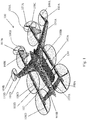
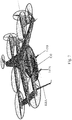
Fig. 1 is a top perspective view of an embodiment of a VTOL drone system having a flying platform and a cargo cabin detachably attached, according to an aspect of the embodiment. -
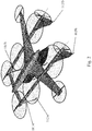
Fig. 2 is a top rear perspective view of the drone system ofFig. 1 . -
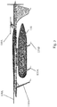
Fig. 3 is a side view of the drone system ofFig. 1 . -
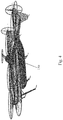
Fig. 4 is a top perspective view of another embodiment of a VTOL drone system having a flying platform and a cabin detachably attached, according to an aspect of the embodiment. -
Fig. 5 is a top view of the drone system ofFig. 4 , according to an aspect of the embodiment. -
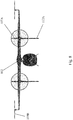
Fig. 6 is a front view of the drone system ofFig. 4 , according to an aspect of the embodiment. -
Fig. 7 is a top perspective view of an embodiment of a VTOL drone system having a flying platform and a passenger cabin detachably attached, according to an aspect of the embodiment. -
Fig. 8 is a front view of the drone system ofFig. 7 , according to an aspect of the embodiment. -
Fig. 9 is a rear perspective view of the drone system ofFig. 7 , according to an aspect of the embodiment. -
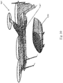
Fig. 10 is a side perspective view of the drone system ofFig. 7 with the passenger cabin detached from the flying platform and resting on the ground, according to an aspect of the embodiment. -
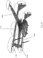
Fig. 11 is a rear perspective view of the embodiment ofFig. 7 , according to an aspect of the embodiment. -
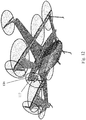
Fig. 12 is a rear perspective view of another embodiment, according to an aspect of the disclosure. -
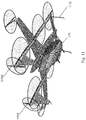
Fig. 13 is a side bottom perspective view of still yet another embodiment of the drone system, according to an aspect of the embodiment. -
Fig. 14 is a perspective view of one embodiment of the drone system, according to another aspect of the embodiment. -
Fig. 15 is a close-up view of the encircled area inFig. 14 , according to another aspect of the embodiment. -
Fig. 16 is a side view of one embodiment of the drone system, according to another aspect of the embodiment. -
Fig. 17 is a front view of one embodiment of the drone system, according to another aspect of the embodiment. -
Fig. 18 is a rear view of one embodiment of the drone system, according to another aspect of the embodiment. -
Fig. 19 is a bottom view of one embodiment of the drone system, according to another aspect of the embodiment. -
Fig. 20 is a perspective view of another embodiment of the flying platform, according to another aspect of the embodiment. -
Fig. 21 is a side view of another embodiment of the flying platform, according to another aspect of the embodiment. -
Fig. 22 is a front view of another embodiment of the flying platform, according to another aspect of the embodiment. -
Fig. 23 is a rear view of another embodiment of the flying platform, according to another aspect of the embodiment. -
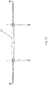
Fig. 24 is a bottom view of another embodiment of the flying platform, according to another aspect of the embodiment. -
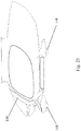
Fig. 25 is a side view of another embodiment of the passenger cabin, according to another aspect of the embodiment. -
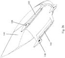
Fig. 26 is a bottom perspective view of another embodiment of the passenger cabin, according to another aspect of the embodiment. -
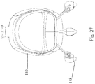
Fig. 27 is a front view of another embodiment of the passenger cabin, according to another aspect of the embodiment. -
Fig. 28 is a rear view of another embodiment of the passenger cabin, according to another aspect of the embodiment. -
Fig. 29 is a bottom view of another embodiment of the passenger cabin, according to another aspect of the embodiment. -
Fig. 30 is a side view of another embodiment of the flying platform attached to a cargo cabin, according to another aspect of the embodiment. -
Fig. 31 is a perspective view of another embodiment of the flying platform having no pushing propellers, according to another aspect of the embodiment. -
Fig. 32 is a side view of another embodiment of the passenger cabin having a pushing propeller, according to another aspect of the embodiment. -
Fig. 33 is a perspective view of yet another embodiment of the flying drone system where six floatation devices are inflated. -
Fig. 34 is a side view of the flying drone offig. 33 . -
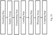
Fig. 35 is a flow diagram showing one embodiment of disclosed methods. - The following call out list of elements in the drawing can be a useful guide when referencing the elements of the drawing figures:
- 100
- Drone
- 101
- Flying platform
- 102
- Main body
- 103A
- Left linear support
- 103B
- Right linear support
- 104A
- Left main wing
- 104B
- Right main wing
- 105A
- Left canard wing
- 105B
- Right canard wing
- 106A
- Left vertical stabilizer
- 106B
- Right vertical stabilizer
- 107
- Pushing propeller
- 107A
- Left pushing propeller
- 107B
- Right pushing propeller
- 108A
- First lifting propeller
- 108B
- Second lifting propeller
- 108C
- Third lifting propeller
- 108D
- Fourth lifting propeller
- 108E
- Fifth lifting propeller
- 108F
- Sixth lifting propeller
- 109A
- Left wing-tip propeller
- 109B
- Right wing-tip propeller
- 110A
- Left wing-tip vertical stabilizer
- 110B
- Right wing-tip vertical stabilizer
- 111A
- Left folding leg
- 111B
- Right folding leg
- 112A
- First leaf spring blade
- 112B
- Second leaf spring blade
- 112C
- Third leaf spring blade
- 112D
- Fourth leaf spring blade
- 116
- Vertical extender
- 117
- Center pushing propeller
- 130
- Cargo cabin
- 135A
- First cabin leaf spring blade
- 135B
- Second cabin leaf spring blade
- 135C
- Third cabin leaf spring blade
- 135D
- Fourth cabin leaf spring blade
- 140
- Passenger cabin
- 145A
- Cabin leg
- 145B
- Cabin leg
- 145C
- Cabin leg
- 145D
- Cabin leg
- 147
- Cabin attachment catch
- 148
- Motorized wheel
- 149
- Housing
- 150
- Energy storage unit in the flying platform
- 155
- Energy storage unit in the cabin
- 160
- Floatation device
- The different aspects of the various embodiments can now be better understood by turning to the following detailed description of the embodiments, which are presented as illustrated examples of the embodiments defined in the claims. It is expressly understood that the embodiments as defined by the claims may be broader than the illustrated embodiments described below.
- The words used in this specification to describe the various embodiments are to be understood not only in the sense of their commonly defined meanings, but to include by special definition in this specification structure, material or acts beyond the scope of the commonly defined meanings. Thus if an element can be understood in the context of this specification as including more than one meaning, then its use in a claim must be understood as being generic to all possible meanings supported by the specification and by the word itself.
- The term "drone" is defined as a flying transportation system having at least one propeller as one source of propulsion. The term "drone" can include "manned" and "unmanned" flying transportation system. A manned drone can mean a flying transportation system that carries human passengers all of who has no control over the drone. A manned drone can also mean a flying transportation system that carries human passengers some or one of who has some control over the drone.
-
Fig. 1 generally depicts an embodiment of VTOLaerial drone 100 having a canard configuration. Thedrone 100 can have twomain wings canard wings main wings canard wings main body 102, wherein the main body can be located alone a center longitudinal line of thedrone 100. There can also be a leftlinear support 103A disposed parallel to themain body 102, and can connect the leftmain wing 104A to theleft canard wing 105A. Similarly, there can also be a rightlinear support 103B disposed parallel to themain body 102, and can connect the rightmain wing 104B to theright canard wing 105B. - In yet another embodiment, the
drone 100 does not have a canard configuration. Instead, thedrone 100 can have two main wings and two secondary wings, all of which are coupled together forming a flying platform. - The left and right
linear supports drone 100. In other embodiments, the left and rightlinear supports propellers linear supports linear supports - In one embodiment, the left and right
linear supports right canard wings linear supports canard wings - In one embodiment, the left and right
linear supports main wings linear supports main wings - The left
linear support 103A is contemplated to be relatively narrow in diameter and may have a plurality of liftingpropellers linear support 103A. These liftingpropellers linear support 103A. In the embodiment shown inFig. 1 , liftingpropellers linear support 103A. - Likewise, the right
linear support 103B is contemplated to be relatively narrow in diameter and may have a plurality of liftingpropellers linear support 103B. These liftingpropellers Fig. 1 , liftingpropellers linear support 103B. - The
drone 100 may have at least one pushing propeller to pushing thedrone 100 in a forward direction. In one embodiment as shown inFig. 1 , there can be two pushingpropellers propellers linear supports - In still yet another embodiment such as one illustrated in
Fig. 31 , the flyingplatform 101 can have no pushing propeller. In such embodiment, the flyingplatform 101 can attach to a passenger cabin or a cargo cabin that has a pushing propeller disposed thereon.Fig. 32 illustrates an embodiment of a passenger cabin having a pushing propeller disposed on its rear end. When this passenger cabin is attached to the flyingplatform 101 ofFig. 31 , the pushing propeller pushes the flyingplatform 101 forward. - Near the rear ends of each
linear support vertical stabilizers - In another embodiment, each of the
main wings additional lifting propeller vertical stabilizers main wings lifting propellers vertical stabilizers tip lifting propellers linear supports - These wing-
tip lifting propellers drone 100. Being located at a most distal position away from the center axis of thedrone 100, these wing-tip lifting propellers drone 100, and can do so with a diameter smaller than that of other lifting propellers. - As shown further in
Fig. 1 , there is acabin 130 generally attached under themain body 102 of thedrone 100. - Referring now to the details of
FIG. 2 , thedrone 100 is contemplated to use any type of landing gear. In one embodiment, thedrone 100 can have four single-blade leaf springs blade leaf springs legs linear supports - The rear two single-blade left springs 112B, 112D are contemplated to be disposed at the bottom distal ends of
vertical stabilizers - The contemplated single-
blade leaf springs - Turning now to
Fig. 3 , which shows the cabin as acargo cabin 130. Thecargo cabin 130 can have single-blade leaf springs - In the contemplated embodiments, the
cargo cabin 130 is detachable from the rest of thedrone 100. The remaining portion of the drone can be called aflying platform 101. The flyingplatform 101 can fly without carrying a cabin, and it can interchangeably carry different cabins. As will be described later, the flyingplatform 101 can also carry passenger cabins. - In the examples shown, all of the
cabins platform 101.Cabins platform 101 is attached to thecabin -
Fig. 5 shows a top view of the flyingplatform 101. It can have a generally flat configuration, capable of carrying a load underneath it, or above it. During high speed flying, all sixlifting propellers main body 102. -
Fig. 5 shows one embodiment of the flyingplatform 101 where thecanard wings main wings -
Fig. 6 generally depicts the frontal view of the flyingplatform 101 with a detachably attachedcargo cabin 130. Whether it is acargo cabin 130,passenger cabin 140, or any other types of load, it is especially contemplated that there can be anenergy storage unit 150 disposed within themain body 102 of the flying platform. The energy stored can be used to power other components of the flying platform, such as the liftingpropellers propellers energy storage 150 can be used to power accessories within thecabin - These
batteries 150 can also be disposed in other parts of the flyingplatform 101, such as within thelinear supports - Alternatively or optionally, there can be an
energy storage unit 155 disposed within thecabin storage unit 155 can be used to power the liftingpropellers propellers energy storage unit 155 in thecabin platform 101 would have replenished energy sources every time the flyingplatform 101 picks up anew cabin platform 101 itself may be emergency energy storage, or asmaller capacity battery 150 necessary to power the flyingplatform 101 for shorter amount of time while it flies without acabin platform 101 comes frombattery 150 located in thecabin platform 101 swaps anold cabin new cabin platform 101 or the entireVTOL drone system 100 would have a fully charged energy source. This is a beneficial method that eliminates the need for a VTOL drone to charge itself. In a preferred embodiment, the flyingplatform 101 can work/fly continuously, picking up cargo cabin/passengers cabin, drop off cargo cabin/passengers cabin, for many hours, even days, without the need to stop for charging its battery. - Referring now to the details of
Fig. 7 , apassenger cabin 150 is provided. Thispassenger cabin 150 can use any type of landing gear, such asstiff legs -
Fig. 10 generally depicts one aspect of the disclosure where the cabin (whether cargo cabin or passenger cabin) is detachable. Here,passenger cabin 140 can be selectively detached from the flyingplatform 101. The engagement and disengagement between the flyingplatform 101 and thecabin 140 can be performed autonomously (without simultaneous user intervention) by a computer and/or other sensors and computing devices. Alternatively or optionally, the user can actively control and direct the engagement and disengagement between the flyingplatform 101 and thecabin 140. - As those of ordinary skill in the art will recognize, various different types of engaging
mechanism 147 can be used to secure thecabin 140 to the flyingplatform 101. For example, the engaging mechanism can be mechanical catches, magnetic catches, tracks and grooves, or a combination of any known engagement means. - It is important to appreciate that besides having the two pushing
propellers Fig. 11 ), alternatively or optionally, there can be acenter pushing propeller 117 coupled to the rear end of the main body 102 (as shown inFig. 12 ). As illustrated inFig. 12 , acenter pushing propeller 117 is connected to the rear end of themain body 102 via avertical extender 116. Thevertical extender 116 can be any structure of any shape to physically couple to pushingpropeller 117 such that the center of rotation for the pushingpropeller 117 is vertically offset from themain body 102. In yet another embodiment, the pushingpropeller 117 is vertically offset from themain body 102 such that the center of rotation for the pushingpropeller 117 is vertically located at a position to the rear of thecabin 140, or vertically level with thecabin 140. In yet another embodiment, the pushingpropeller 117 is vertically level with the top portion of thecabin 140. In still yet another embodiment, the pushingpropeller 117 is vertically level with the middle portion of thecabin 140. In a further embodiment, the pushingpropeller 117 is vertically level with the bottom portion of thecabin 140. - Not shown in any of the figures is an embodiment where there are no pushing
propellers linear supports propeller 117 coupled to the rear end of themain body 102. - It is also contemplated that each
linear support Fig. 13 shows one embodiment where twoadditional lifting propellers 108G, 108H are provided at the bottom front ends oflinear support - While the pushing
propellers linear supports propellers main wings Fig. 13 . In one aspect, these pushingpropellers cabin platform 101. In another aspect, these pushingpropellers vertical stabilizers propellers cabin -
Figs. 14 to 30 illustrate embodiments where the flyingplatform 101 or thecabin wheels 148 attached thereon. In the embodiment ofFig. 14 , the flyingplatform 101 has motorizedwheels 148; thecabin Fig. 15 , a single unit ofmotorized wheel 148 can have a motor enclosed in ahousing 149, and the motor can be driven by electricity supplied by theenergy storage unit 150 disposed in thecabin - The contemplated
motorized wheel 148 can move the flyingplatform 101 and thecabin 130 across the ground, when they are resting on the ground. This allows acabin platform 101, and allows anothercabin platform 101 for coupling. - Alternatively, this can allow a
flying platform 101 to wheel away from thecabin 130 and towards another cabin for coupling. In one embodiment, everycabin energy storage unit 155 so that when the flyingplatform 101 couples to a new and fully chargedcabin platform 101 essentially has replenished its source of energy. - In some embodiments of the disclosed drone system there can be provided at least one
floatation device 160 coupled to at least one of thecargo cabin 130,passenger cabin 140, and the flyingplatform 101. The contemplate floatation device can be a type that requires actuation, that is, active inflation with gas or upon material when needed. In other words, in this particular embodiment, thefloatation device 160 can remain in a deflated state and is inflated only when certain conditions triggers the inflation. For example, thefloatation device 160 can be automatically inflated during emergency landing; it can be inflated automatically during water landing; it can be inflated when any of the landing gears malfunction in some ways. - Many known types of inflation mechanism or air bag mechanism may be implemented to achieve the needs and constructions of the disclosed
floatation device 160. The contemplatedfloatation device 160 may be a type that can be reused, re-inflated, re-deflated, over and over. The contemplatedfloatation device 160 can also be of one-time use only. - Alternatively or optionally, the act of inflation can be user activated. For example, when the operator of the drone system determines a need for inflating the
floatation device 160, he or she may send a signal to initiate inflation. - It should be particularly noted in some embodiments, the
floatation device 160 does not require the existence ofmotorized wheels 148. In other embodiments, thefloatation device 160 is part of the housing for themotorized wheel 148. - Referring to
Fig. 26 as one example, apassenger cabin 140 can have anelongated floatation device 160 disposed on either sides of thecabin 140 that can perform as a water landing gear. InFig. 26 , thesefloatation devices 160 are shown as deflated.Fig. 32 shows a side view of a deflatedfloatation device 160. InFigs. 33 and34 , thefloatation device 160 coupled to thepassenger cabin 140 are shown as inflated. - Referring to
Fig. 31 as another example, a flyingplatform 101 can have fourfloatation devices 160 disposed on top of each of the fourmotorized wheels 148. Thesefloatation devices 160 may alternatively attach to or near themotorized wheels 148 at other locations. InFig. 31 , thesefloatation devices 160 that are coupled to themotorized wheels 148 are shown as deflated.Figs. 33 and34 show floatation devices 160 of the flyingplatform 101 being inflated. - This disclosure also provides a method of managing a system of aerial drone transport and drone energy charging. Referring now to
Fig. 35 , one contemplated method can include attaching afirst cabin platform 101 to transport the first cabin (whether the first cabin is acargo cabin 130 or a passenger cabin 140) by flying using the flyingplatform 101 as a primary source of propulsion. - Of the many contemplated methods possible, one embodiment of the disclosed methods can also include the step of providing at least one set of propellers on the flying
platform 101. These can be pushing propellers or lifting propellers as described above. - It is also contemplated to include a step of supplying a first unit of energy from a first energy storage unit disposed within the
first cabin platform 101 to drive the at least one set of propeller when thefirst cabin - In one embodiment, the method further includes landing the flying
platform 101 on a ground while thefirst cabin platform 101. - The method can further include a detaching step after the landing step, by detaching the
first cabin platform 101. This is typically done while the flyingplatform 101 has landed on the ground. - Further contemplated is a wheeling step after the detaching step. In this embodiment, the method includes wheeling the
first cabin platform 101 using at least a first set of motorized wheels disposed on thefirst cabin empty cabins platform 101. This allows asingle flying platform 101 to quickly drop off and pick updifferent cabins cabin - In one embodiment, a method can have a coupling step after the wheeling step, by coupling a
second cabin platform 101. Thesecond cabin motorized wheels 148 and a secondenergy storage unit 155 disposed therein. - In one other embodiment, the wheeling away step is controlled by a microprocessor, sensors, and is performed automatically in a robotic fashion.
- In yet another embodiment, the second
energy storage unit 155 can supply a second unit of energy to the flyingplatform 101 to drive the flying platform's propeller as a primary source of energy, thereby allowing the flyingplatform 101 to continue flying without directly charging the flyingplatform 101. In other words, continuous flight of the flyingplatform 101 and non-stop transport of cargos and passengers can now be possible. - Many alterations and modifications may be made by those having ordinary skill in the art without departing from the spirit and scope of the disclosed embodiments. Therefore, it must be understood that the illustrated embodiments have been set forth only for the purposes of example and that it should not be taken as limiting the embodiments as defined by the following claims. For example, notwithstanding the fact that the elements of a claim are set forth below in a certain combination, it must be expressly understood that the embodiment includes other combinations of fewer, more or different elements, which are disclosed herein even when not initially claimed in such combinations.
- Thus, specific embodiments and applications of VTOL flying platform with interchangeable cabins have been disclosed. It should be apparent, however, to those skilled in the art that many more modifications besides those already described are possible without departing from the disclosed concepts herein. The disclosed embodiments, therefore, is not to be restricted except in the spirit of the appended claims. Moreover, in interpreting both the specification and the claims, all terms should be interpreted in the broadest possible manner consistent with the context. In particular, the terms "comprises" and "comprising" should be interpreted as referring to elements, components, or steps in a non-exclusive manner, indicating that the referenced elements, components, or steps may be present, or utilized, or combined with other elements, components, or steps that are not expressly referenced. Insubstantial changes from the claimed subject matter as viewed by a person with ordinary skill in the art, now known or later devised, are expressly contemplated as being equivalent within the scope of the claims. Therefore, obvious substitutions now or later known to one with ordinary skill in the art are defined to be within the scope of the defined elements. The claims are thus to be understood to include what is specifically illustrated and described above, what is conceptually equivalent, what can be obviously substituted and also what essentially incorporates the essential idea of the embodiments. In addition, where the specification and claims refer to at least one of something selected from the group consisting of A, B, C .... and N, the text should be interpreted as requiring at least one element from the group which includes N, not A plus N, or B plus N, etc.
Claims (20)
- A VTOL (vertical take-off and landing) aerial drone comprising:a flying platform (101) having:a left main wing (104A) and a right main wing (104B);a left secondary wing (105A) and a right secondary wing (105B);a main body (102) coupled to the left main wing (104A) and the right main wing (104B);a left linear support (103A) connecting the left main wing (104A) to the left secondary wing (105A);a right linear support (103B) connecting the right main wing (104B) to the right secondary wing (105B);the left linear support (103A) has a first, a second, a third lifting propellers, and a left vertical stabilizer (106A);the right linear support (103B) has a fourth, a fifth, a sixth lifting propellers and a right vertical stabilizer (106B);a cargo cabin (130) or a passenger cabin (140) being detachably coupled to the flying platform (101); andat least one pushing propeller (107A, 107B; 117) coupled to either the platform (101) or the cabin (130; 140).
- The aerial drone as recited in claim 1 further comprising a first energy storage unit (155) disposed in the cargo cabin (130) and/or the passenger cabin (140) configured to supply energy to the flying platform (101).
- The aerial drone as recited in claim 1 further comprising an inflatable floatation device (160) coupled to at least one of the passenger cabin (140), cargo cabin (130), and flying platform (101).
- The aerial drone as recited in claim 1, wherein the left linear support (103A) has a seventh lifting propeller (108G) disposed on an underside of the left linear support (103A), and the right linear support (103B) has an eighth lifting propeller (108H) disposed on an underside of the right linear support (103B).
- The aerial drone as recited in claim 1 the further comprising a left wing-tip propeller (109A) disposed on the distal end of the left main wing (104A), and a right wing-tip propeller (109B) disposed on the distal end of the right main wing (104B),
- The aerial drone as recited in claim 1, wherein the at least one pushing propeller (107A, 107B; 117) is disposed so as to be horizontally level with the cargo cabin (130) or the passenger cabin (140).
- The aerial drone as recited in claim 6, wherein the at least one pushing propeller includes a left pushing propeller (107A) disposed in a mid-section of the left vertical stabilizer (106A), and a right pushing propeller (107B) disposed in a mid-section of the right vertical stabilizer (106B).
- The aerial drone as recited in claim 6, wherein the at least one pushing propeller (117) is coupled to a rear end of the main body (102) and is extended downward away from the main body (102).
- The aerial drone as recited in claim 6, wherein the at least one pushing propeller (107) is disposed on a rear end of the said cargo cabin (130) or said passenger cabin (140).
- The aerial drone as recited in claim 1 further comprising autonomous flight functions and the passenger cabin (140) includes user control interface to manually control flight functions.
- The aerial drone as recited in claim 1, wherein the passenger cabin (140) and the cargo cabin (130) can be detachably attached to the bottom of the flying platform (101).
- The aerial drone as recited in claim 11 further comprising a second energy storage unit (150) disposed within the flying platform (101), and the flying platform (101) is configured to fly on its own without being attached to any one of said passenger cabin (140) and cargo cabin (130).
- The aerial drone as recited in claim 1, wherein the flying platform (101) has at least one motorized wheel (148) configured to move the flying platform (101) across a surface of a ground.
- The aerial drone as recited in claim 13, wherein the at least one motorized wheel (148) is disposed at a distal end of a folding leg (111), which is retrievable within the linear support (103A; 103B).
- The aerial drone as recited in claim 1, wherein both the passenger cabin (140) and the cargo cabin (130) each has at least one motorized wheel (148) configured to move the passenger cabin (140) and the cargo cabin (130) across a surface of a ground.
- A method of managing a system of aerial drone transport and energy charging, the method comprising:attaching a first cabin (130; 140) to a flying platform (101) to transport said first cabin (130; 140) via flight using said flying platform (101) as a primary source of propulsion;providing at least one set of propeller on the flying platform (101);supplying a first unit of energy from a first energy storage unit (155) disposed within the first cabin (130; 140), to the flying platform (101) to drive the at least one set of propeller when the first cabin (130; 140) is attached to the flying platform (101);landing the flying platform (101) on a ground wherein the first cabin (130; 140) is attached to the flying platform (101); andwherein the first cabin (130; 140) contains a passenger and/or a cargo.
- The method as recited in claim 16, wherein after the landing step, detaching the first cabin (130; 140) from the flying platform (101).
- The method as recited in claim 17, wherein after the detaching step, wheeling the first cabin (130; 140) away from the flying platform (101) using at least a first set of motorized wheels (148) disposed on the first cabin (130; 140).
- The method as recited in claim 18, wherein after the wheeling step, coupling a second cabin (130; 140) to the flying platform (101), and wherein the second cabin (130; 140) has at least a second set of motorized wheels (148) and a second energy storage unit (155) disposed therein; wherein the second cabin (130; 140) contains another passenger and/or another cargo.
- The method as recited in claim 19, wherein the second energy storage unit (155) supplies a second unit of energy to the platform (101) to drive the at least one set of propeller as an primary source of energy, thereby allowing the flying platform (101) to continue flying without directly charging the flying platform (101).
Applications Claiming Priority (1)
| Application Number | Priority Date | Filing Date | Title |
|---|---|---|---|
| US16/281,020 US20190233077A1 (en) | 2018-01-29 | 2019-02-20 | Vtol fixed-wing flying platform system |
Publications (2)
| Publication Number | Publication Date |
|---|---|
| EP3698995A1 true EP3698995A1 (en) | 2020-08-26 |
| EP3698995B1 EP3698995B1 (en) | 2022-04-20 |
Family
ID=69779744
Family Applications (1)
| Application Number | Title | Priority Date | Filing Date |
|---|---|---|---|
| EP20158443.0A Active EP3698995B1 (en) | 2019-02-20 | 2020-02-20 | Vtol fixed-wing flying platform system |
Country Status (4)
| Country | Link |
|---|---|
| US (1) | US11440654B2 (en) |
| EP (1) | EP3698995B1 (en) |
| CN (1) | CN111688920B (en) |
| ES (1) | ES2916077T3 (en) |
Cited By (2)
| Publication number | Priority date | Publication date | Assignee | Title |
|---|---|---|---|---|
| CN116674774A (en) * | 2023-06-29 | 2023-09-01 | 哈尔滨工业大学 | Ground deployment device and method for Mars aircraft |
| RU2827271C1 (en) * | 2024-02-27 | 2024-09-23 | Сергей Васильевич Григорьев | Convertible three-medium vehicle with fifteen seats |
Families Citing this family (15)
| Publication number | Priority date | Publication date | Assignee | Title |
|---|---|---|---|---|
| US20180162525A1 (en) * | 2016-12-08 | 2018-06-14 | Aurora Flight Sciences Corporation | Double-Blown Wing Vertical Takeoff and Landing Aircraft |
| US11753146B1 (en) * | 2018-07-09 | 2023-09-12 | Pinto Geoffrey P | VTOL aircraft having modular payload |
| US12012187B2 (en) * | 2021-03-18 | 2024-06-18 | The United States Of America, As Represented By The Secretary Of The Navy | Maritime overboard locator and response system |
| US11760474B2 (en) * | 2021-06-06 | 2023-09-19 | Xi Wang | VTOL box-wing multirotor aerial vehicle |
| KR20220166117A (en) * | 2021-06-09 | 2022-12-16 | 현대자동차주식회사 | Mobility vehicle transfer platform |
| JP1714479S (en) * | 2021-09-27 | 2022-05-11 | Manned aircraft | |
| CN216805836U (en) * | 2021-11-22 | 2022-06-24 | 上海峰飞航空科技有限公司 | Modular unmanned aerial vehicle that hangs down |
| TWI814260B (en) * | 2022-02-23 | 2023-09-01 | 國立陽明交通大學 | Triple-purposes unmanned vehicle |
| USD1035547S1 (en) * | 2022-06-17 | 2024-07-16 | Autel Robotics Co., Ltd. | Aerial vehicle |
| USD1031516S1 (en) * | 2022-09-13 | 2024-06-18 | Autel Robotics Co., Ltd. | Drone |
| USD1030555S1 (en) * | 2022-09-13 | 2024-06-11 | Autel Robotics Co., Ltd. | Drone |
| CN115571327B (en) * | 2022-12-07 | 2023-03-17 | 北京启时智航科技有限公司 | Distributed electric propulsion ultra-short take-off and landing fixed-wing aircraft platform |
| WO2025116895A1 (en) * | 2023-11-28 | 2025-06-05 | Spydar Sensors Incorporated | A vertical takeoff and landing assistance aircraft using fixed angle ducted motors |
| CN118544743A (en) * | 2024-04-30 | 2024-08-27 | 清华大学 | Flying vehicle and control method for flying vehicle |
| US20250375991A1 (en) * | 2025-08-22 | 2025-12-11 | Guanhao Wu | Dual-Mode Vehicle with Selectively Attachable Flight Module and Energy Transmission Control |
Citations (7)
| Publication number | Priority date | Publication date | Assignee | Title |
|---|---|---|---|---|
| DE19745492A1 (en) * | 1997-10-15 | 1999-04-22 | Aloys Wobben | Vertical take off aircraft |
| US20060151666A1 (en) * | 2005-01-13 | 2006-07-13 | Vandermey Timothy | Vertical take-off and landing (VTOL) aircraft with distributed thrust and control |
| US8876057B2 (en) * | 2006-07-27 | 2014-11-04 | Sikorsky Aircraft Corporation | Aerodynamic integration of a payload container with a vertical take-off and landing aircraft |
| CN207346074U (en) * | 2017-11-03 | 2018-05-11 | 西安冰果智能航空科技有限公司 | A kind of double shoe VTOL fixed-wing unmanned planes of normal arrangement |
| US20180305005A1 (en) * | 2017-04-24 | 2018-10-25 | AFS-DV VTOL Technologies Corporation | Vertical Take-Off and Landing Aircraft |
| US20180320402A1 (en) * | 2016-09-09 | 2018-11-08 | Michael Steward Evans | Intelligent POD Management and Transport |
| US20190009899A1 (en) * | 2017-07-06 | 2019-01-10 | Autoflightx International Limited | Hybrid vtol fixed-wing drone having wing-tip propellers |
Family Cites Families (47)
| Publication number | Priority date | Publication date | Assignee | Title |
|---|---|---|---|---|
| GB1472950A (en) * | 1974-07-23 | 1977-05-11 | Goodrich Co B F | Inflatable escape slide raft |
| US4298177A (en) * | 1979-11-09 | 1981-11-03 | Berlongieri John J | Aircraft safety apparatus |
| US6409122B1 (en) * | 2001-01-17 | 2002-06-25 | Lockheed Martin Corporation | Anti-submarine warfare UAV and method of use thereof |
| US7156033B2 (en) * | 2002-08-19 | 2007-01-02 | Floatlogic, Inc. | Inflating aircraft flotation device |
| US9493235B2 (en) * | 2002-10-01 | 2016-11-15 | Dylan T X Zhou | Amphibious vertical takeoff and landing unmanned device |
| US20110226174A1 (en) * | 2008-06-16 | 2011-09-22 | Aurora Flight Sciences Corporation | Combined submersible vessel and unmanned aerial vehicle |
| EP2576342A4 (en) * | 2010-05-26 | 2014-08-20 | Aerovironment Inc | RECONFIGURABLE VEHICLE SYSTEM OPERATING ON BATTERY |
| TWI538852B (en) * | 2011-07-19 | 2016-06-21 | 季航空股份有限公司 | Personal aircraft |
| FR3017107A1 (en) * | 2014-01-31 | 2015-08-07 | Airbus Helicopters | FLOATING SYSTEM FOR AIRCRAFT AND AIRCRAFT |
| FR3030451A1 (en) * | 2014-12-22 | 2016-06-24 | Parrot | ACCESSORY TO MAKE AN AMPHIBIOUS DRONE |
| WO2017185378A1 (en) * | 2016-04-29 | 2017-11-02 | SZ DJI Technology Co., Ltd. | Systems and methods for uav transport and data acquisition |
| CN106976367B (en) * | 2016-06-16 | 2019-02-12 | 姜忠昱 | One kind three is dwelt unmanned plane |
| CN106005434B (en) * | 2016-06-30 | 2018-12-11 | 河南正大航空科技股份有限公司 | A kind of boat-carrying unmanned plane based on Internet of Things traveling waterborne protects system |
| CN205971824U (en) * | 2016-07-28 | 2017-02-22 | 顺丰科技有限公司 | Unmanned aerial vehicle |
| US10065738B2 (en) * | 2016-08-22 | 2018-09-04 | Harris Corporation | Tethered unmanned aerial vehicle |
| IL247772B (en) * | 2016-09-12 | 2022-05-01 | Israel Aerospace Ind Ltd | Modular vehicle system |
| CN106564349A (en) * | 2016-10-31 | 2017-04-19 | 广东工业大学 | Triphibian unmanned aerial vehicle |
| US11548633B2 (en) * | 2016-12-31 | 2023-01-10 | Jayant Ratti | High endurance unmanned aerial vehicle |
| CN206857012U (en) * | 2017-05-02 | 2018-01-09 | 韩文级 | Aircraft and pilot save oneself equipment |
| US10053213B1 (en) * | 2017-05-08 | 2018-08-21 | Pinnacle Vista, LLC | Multi-copter lift body aircraft with tail pusher |
| CN107097952A (en) * | 2017-05-10 | 2017-08-29 | 郑州航空工业管理学院 | A kind of novel and multifunctional boxlike connection wing aquatic unmanned aerial vehicle |
| CN107696811A (en) * | 2017-09-03 | 2018-02-16 | 佛山市龙远科技有限公司 | A kind of VTOL amphibious unmanned plane of more power |
| US11628933B2 (en) * | 2017-10-27 | 2023-04-18 | Elroy Air, Inc. | Compound multi-copter aircraft |
| CN107933914B (en) * | 2017-11-08 | 2020-11-10 | 上海交通大学 | Water-air amphibious sightseeing electric rotor aircraft |
| US10472064B2 (en) * | 2018-01-29 | 2019-11-12 | Yu Tian | VTOL fixed-wing aerial drone with interchangeable cabins |
| US20210380235A1 (en) * | 2018-05-15 | 2021-12-09 | Evangelos Livieratos | Breaching for submergible fixed wing aircraft |
| CN108725778B (en) * | 2018-05-29 | 2020-11-03 | 北京航空航天大学 | Amphibious unmanned aerial vehicle with duck wings and variable wing dihedral angles |
| US11136096B2 (en) * | 2018-07-25 | 2021-10-05 | Thomas Lawrence Moses | Unmanned aerial vehicle search and rescue system |
| CN109353500A (en) * | 2018-11-08 | 2019-02-19 | 南京航空航天大学 | A hydrofoil-mounted multi-roof aircraft |
| KR102128678B1 (en) * | 2019-01-31 | 2020-07-01 | 부산대학교 산학협력단 | Unmanned aerial vehicle for rescue |
| KR102128677B1 (en) * | 2019-01-31 | 2020-07-01 | 부산대학교 산학협력단 | Maritime Propulsion Unmanned Aerial Vehicle |
| CN110154658B (en) * | 2019-05-29 | 2022-06-07 | 吉林大学 | Combined bionic cross-medium variant unmanned aircraft based on shapes of kingfishers and psyllids |
| CN110282129A (en) * | 2019-06-13 | 2019-09-27 | 广东工业大学 | A kind of cross coaxial amphibious unmanned plane of tilting rotor |
| CN112572702A (en) * | 2019-09-29 | 2021-03-30 | 刘春梅 | Flight detection ship |
| EP3798124B1 (en) * | 2019-09-30 | 2023-01-18 | Shanghai Autoflight Co., Ltd. | Amphibious drone |
| US11542004B2 (en) * | 2019-10-11 | 2023-01-03 | Textron Systems Corporation | Maneuverability involving a fixed-wing aircraft and an aerial vehicle having vertical takeoff and landing capabilities |
| CN110667838A (en) * | 2019-11-06 | 2020-01-10 | 珠海市高新区家有飞行器科技有限公司 | Solar energy telescopic wing water-air dual-purpose unmanned aerial vehicle |
| US11511832B2 (en) * | 2020-02-04 | 2022-11-29 | They | Amphibious aircraft taxiing and docking systems |
| US11702201B2 (en) * | 2020-06-18 | 2023-07-18 | They | Amphibious aircraft taxiing systems |
| US12043419B2 (en) * | 2020-02-27 | 2024-07-23 | Liviu Giurca | Aircraft with vertical take-off and landing—VTOL |
| US11453493B2 (en) * | 2020-04-14 | 2022-09-27 | Aurora Flight Sciences Corporation | Submergible aerial vehicle |
| CN112124583B (en) * | 2020-08-27 | 2022-10-25 | 杨嘉鹏 | H-shaped four-rotor amphibious unmanned aerial vehicle with Magnus anti-rolling device |
| US11066145B1 (en) * | 2020-08-28 | 2021-07-20 | H2 Clipper, Inc. | Method and apparatus for lighter-than-air airship with improved structure and delivery system |
| KR102225588B1 (en) * | 2020-10-22 | 2021-03-09 | 주식회사 아스트로엑스 | Personal air veihcle |
| CN112758314B (en) * | 2020-12-15 | 2022-07-26 | 北京交通大学 | Deformable composite wing cross-medium flying submersible vehicle |
| CN113306354A (en) * | 2021-06-17 | 2021-08-27 | 中国人民解放军海军工程大学 | Air-water integrated propulsion system of amphibious aircraft |
| CN113247250B (en) * | 2021-06-28 | 2022-08-30 | 天津大学 | Ferry airship |
-
2019
- 2019-07-25 CN CN201910678334.7A patent/CN111688920B/en active Active
-
2020
- 2020-02-20 EP EP20158443.0A patent/EP3698995B1/en active Active
- 2020-02-20 ES ES20158443T patent/ES2916077T3/en active Active
-
2021
- 2021-08-08 US US17/396,733 patent/US11440654B2/en active Active
Patent Citations (7)
| Publication number | Priority date | Publication date | Assignee | Title |
|---|---|---|---|---|
| DE19745492A1 (en) * | 1997-10-15 | 1999-04-22 | Aloys Wobben | Vertical take off aircraft |
| US20060151666A1 (en) * | 2005-01-13 | 2006-07-13 | Vandermey Timothy | Vertical take-off and landing (VTOL) aircraft with distributed thrust and control |
| US8876057B2 (en) * | 2006-07-27 | 2014-11-04 | Sikorsky Aircraft Corporation | Aerodynamic integration of a payload container with a vertical take-off and landing aircraft |
| US20180320402A1 (en) * | 2016-09-09 | 2018-11-08 | Michael Steward Evans | Intelligent POD Management and Transport |
| US20180305005A1 (en) * | 2017-04-24 | 2018-10-25 | AFS-DV VTOL Technologies Corporation | Vertical Take-Off and Landing Aircraft |
| US20190009899A1 (en) * | 2017-07-06 | 2019-01-10 | Autoflightx International Limited | Hybrid vtol fixed-wing drone having wing-tip propellers |
| CN207346074U (en) * | 2017-11-03 | 2018-05-11 | 西安冰果智能航空科技有限公司 | A kind of double shoe VTOL fixed-wing unmanned planes of normal arrangement |
Non-Patent Citations (2)
| Title |
|---|
| ANONYMOUS: "Airbus' new concept is a car, a drone, and a train all in one - The Verge", 7 March 2017 (2017-03-07), XP055625021, Retrieved from the Internet <URL:https://www.theverge.com/2017/3/7/14841324/airbus-concept-car-drone-train-geneva-motor-show> [retrieved on 20190923] * |
| MARCO MARGARITOFF: "Elroy Air's 'Aluminum Falcon' VTOL Drone Can Carry Up to 150 Pounds - The Drive", 22 December 2017 (2017-12-22), XP055624700, Retrieved from the Internet <URL:https://www.thedrive.com/aerial/17176/elroy-airs-aluminum-falcon-vtol-drone-can-carry-up-to-150-pounds> [retrieved on 20190920] * |
Cited By (2)
| Publication number | Priority date | Publication date | Assignee | Title |
|---|---|---|---|---|
| CN116674774A (en) * | 2023-06-29 | 2023-09-01 | 哈尔滨工业大学 | Ground deployment device and method for Mars aircraft |
| RU2827271C1 (en) * | 2024-02-27 | 2024-09-23 | Сергей Васильевич Григорьев | Convertible three-medium vehicle with fifteen seats |
Also Published As
| Publication number | Publication date |
|---|---|
| US11440654B2 (en) | 2022-09-13 |
| US20220041280A1 (en) | 2022-02-10 |
| CN111688920B (en) | 2024-02-02 |
| CN111688920A (en) | 2020-09-22 |
| EP3698995B1 (en) | 2022-04-20 |
| ES2916077T3 (en) | 2022-06-28 |
Similar Documents
| Publication | Publication Date | Title |
|---|---|---|
| EP3698995A1 (en) | Vtol fixed-wing flying platform system | |
| US20190233077A1 (en) | Vtol fixed-wing flying platform system | |
| US10472064B2 (en) | VTOL fixed-wing aerial drone with interchangeable cabins | |
| CN213974458U (en) | Vertical take-off and landing aerial unmanned aerial vehicle and cooling system for aerial unmanned aerial vehicle | |
| CN213974457U (en) | Vertical take-off and landing aerial unmanned aerial vehicle | |
| US11535372B2 (en) | Method of navigating an amphibious aerial vehicle on water | |
| US10472058B2 (en) | VTOL aircraft with step-up overlapping propellers | |
| US11745866B2 (en) | Fixed-wing UAV with lifting propellers and traction propellers | |
| EP3708492B1 (en) | Vtol aircraft with step-up overlapping propellers | |
| US20210362866A1 (en) | Unmanned Aerial Vehicle Power System for Minimizing Propulsion Failure | |
| US11407508B2 (en) | Vertical takeoff and landing aerial vehicle | |
| EP3560828B1 (en) | Vtol fixed-wing aerial drone with interchangeable cabins | |
| CN213384708U (en) | Vertical take-off and landing aerial unmanned aerial vehicle and cooling system for aerial unmanned aerial vehicle | |
| CN213384709U (en) | Vertical take-off and landing aerial unmanned aerial vehicle | |
| CN214029130U (en) | Fixed-wing UAV | |
| CN213974456U (en) | Vertical take-off and landing aerial unmanned aerial vehicle | |
| CN213974454U (en) | Vertical take-off and landing aerial unmanned aerial vehicle and cooling system for aerial unmanned aerial vehicle | |
| CN213974455U (en) | Unmanned aerial vehicle and driving system thereof, system for minimizing unmanned aerial vehicle fault |
Legal Events
| Date | Code | Title | Description |
|---|---|---|---|
| PUAI | Public reference made under article 153(3) epc to a published international application that has entered the european phase |
Free format text: ORIGINAL CODE: 0009012 |
|
| STAA | Information on the status of an ep patent application or granted ep patent |
Free format text: STATUS: REQUEST FOR EXAMINATION WAS MADE |
|
| 17P | Request for examination filed |
Effective date: 20200331 |
|
| AK | Designated contracting states |
Kind code of ref document: A1 Designated state(s): AL AT BE BG CH CY CZ DE DK EE ES FI FR GB GR HR HU IE IS IT LI LT LU LV MC MK MT NL NO PL PT RO RS SE SI SK SM TR |
|
| AX | Request for extension of the european patent |
Extension state: BA ME |
|
| GRAP | Despatch of communication of intention to grant a patent |
Free format text: ORIGINAL CODE: EPIDOSNIGR1 |
|
| STAA | Information on the status of an ep patent application or granted ep patent |
Free format text: STATUS: GRANT OF PATENT IS INTENDED |
|
| INTG | Intention to grant announced |
Effective date: 20211105 |
|
| GRAS | Grant fee paid |
Free format text: ORIGINAL CODE: EPIDOSNIGR3 |
|
| GRAA | (expected) grant |
Free format text: ORIGINAL CODE: 0009210 |
|
| STAA | Information on the status of an ep patent application or granted ep patent |
Free format text: STATUS: THE PATENT HAS BEEN GRANTED |
|
| AK | Designated contracting states |
Kind code of ref document: B1 Designated state(s): AL AT BE BG CH CY CZ DE DK EE ES FI FR GB GR HR HU IE IS IT LI LT LU LV MC MK MT NL NO PL PT RO RS SE SI SK SM TR |
|
| REG | Reference to a national code |
Ref country code: GB Ref legal event code: FG4D |
|
| REG | Reference to a national code |
Ref country code: CH Ref legal event code: EP |
|
| REG | Reference to a national code |
Ref country code: IE Ref legal event code: FG4D |
|
| REG | Reference to a national code |
Ref country code: DE Ref legal event code: R096 Ref document number: 602020002697 Country of ref document: DE |
|
| REG | Reference to a national code |
Ref country code: AT Ref legal event code: REF Ref document number: 1484904 Country of ref document: AT Kind code of ref document: T Effective date: 20220515 |
|
| REG | Reference to a national code |
Ref country code: ES Ref legal event code: FG2A Ref document number: 2916077 Country of ref document: ES Kind code of ref document: T3 Effective date: 20220628 |
|
| REG | Reference to a national code |
Ref country code: LT Ref legal event code: MG9D |
|
| REG | Reference to a national code |
Ref country code: NL Ref legal event code: MP Effective date: 20220420 |
|
| REG | Reference to a national code |
Ref country code: AT Ref legal event code: MK05 Ref document number: 1484904 Country of ref document: AT Kind code of ref document: T Effective date: 20220420 |
|
| PG25 | Lapsed in a contracting state [announced via postgrant information from national office to epo] |
Ref country code: NL Free format text: LAPSE BECAUSE OF FAILURE TO SUBMIT A TRANSLATION OF THE DESCRIPTION OR TO PAY THE FEE WITHIN THE PRESCRIBED TIME-LIMIT Effective date: 20220420 |
|
| PG25 | Lapsed in a contracting state [announced via postgrant information from national office to epo] |
Ref country code: SE Free format text: LAPSE BECAUSE OF FAILURE TO SUBMIT A TRANSLATION OF THE DESCRIPTION OR TO PAY THE FEE WITHIN THE PRESCRIBED TIME-LIMIT Effective date: 20220420 Ref country code: PT Free format text: LAPSE BECAUSE OF FAILURE TO SUBMIT A TRANSLATION OF THE DESCRIPTION OR TO PAY THE FEE WITHIN THE PRESCRIBED TIME-LIMIT Effective date: 20220822 Ref country code: NO Free format text: LAPSE BECAUSE OF FAILURE TO SUBMIT A TRANSLATION OF THE DESCRIPTION OR TO PAY THE FEE WITHIN THE PRESCRIBED TIME-LIMIT Effective date: 20220720 Ref country code: LT Free format text: LAPSE BECAUSE OF FAILURE TO SUBMIT A TRANSLATION OF THE DESCRIPTION OR TO PAY THE FEE WITHIN THE PRESCRIBED TIME-LIMIT Effective date: 20220420 Ref country code: HR Free format text: LAPSE BECAUSE OF FAILURE TO SUBMIT A TRANSLATION OF THE DESCRIPTION OR TO PAY THE FEE WITHIN THE PRESCRIBED TIME-LIMIT Effective date: 20220420 Ref country code: GR Free format text: LAPSE BECAUSE OF FAILURE TO SUBMIT A TRANSLATION OF THE DESCRIPTION OR TO PAY THE FEE WITHIN THE PRESCRIBED TIME-LIMIT Effective date: 20220721 Ref country code: FI Free format text: LAPSE BECAUSE OF FAILURE TO SUBMIT A TRANSLATION OF THE DESCRIPTION OR TO PAY THE FEE WITHIN THE PRESCRIBED TIME-LIMIT Effective date: 20220420 Ref country code: BG Free format text: LAPSE BECAUSE OF FAILURE TO SUBMIT A TRANSLATION OF THE DESCRIPTION OR TO PAY THE FEE WITHIN THE PRESCRIBED TIME-LIMIT Effective date: 20220720 Ref country code: AT Free format text: LAPSE BECAUSE OF FAILURE TO SUBMIT A TRANSLATION OF THE DESCRIPTION OR TO PAY THE FEE WITHIN THE PRESCRIBED TIME-LIMIT Effective date: 20220420 |
|
| PG25 | Lapsed in a contracting state [announced via postgrant information from national office to epo] |
Ref country code: RS Free format text: LAPSE BECAUSE OF FAILURE TO SUBMIT A TRANSLATION OF THE DESCRIPTION OR TO PAY THE FEE WITHIN THE PRESCRIBED TIME-LIMIT Effective date: 20220420 Ref country code: PL Free format text: LAPSE BECAUSE OF FAILURE TO SUBMIT A TRANSLATION OF THE DESCRIPTION OR TO PAY THE FEE WITHIN THE PRESCRIBED TIME-LIMIT Effective date: 20220420 Ref country code: LV Free format text: LAPSE BECAUSE OF FAILURE TO SUBMIT A TRANSLATION OF THE DESCRIPTION OR TO PAY THE FEE WITHIN THE PRESCRIBED TIME-LIMIT Effective date: 20220420 Ref country code: IS Free format text: LAPSE BECAUSE OF FAILURE TO SUBMIT A TRANSLATION OF THE DESCRIPTION OR TO PAY THE FEE WITHIN THE PRESCRIBED TIME-LIMIT Effective date: 20220820 |
|
| REG | Reference to a national code |
Ref country code: DE Ref legal event code: R097 Ref document number: 602020002697 Country of ref document: DE |
|
| PG25 | Lapsed in a contracting state [announced via postgrant information from national office to epo] |
Ref country code: SM Free format text: LAPSE BECAUSE OF FAILURE TO SUBMIT A TRANSLATION OF THE DESCRIPTION OR TO PAY THE FEE WITHIN THE PRESCRIBED TIME-LIMIT Effective date: 20220420 Ref country code: SK Free format text: LAPSE BECAUSE OF FAILURE TO SUBMIT A TRANSLATION OF THE DESCRIPTION OR TO PAY THE FEE WITHIN THE PRESCRIBED TIME-LIMIT Effective date: 20220420 Ref country code: RO Free format text: LAPSE BECAUSE OF FAILURE TO SUBMIT A TRANSLATION OF THE DESCRIPTION OR TO PAY THE FEE WITHIN THE PRESCRIBED TIME-LIMIT Effective date: 20220420 Ref country code: EE Free format text: LAPSE BECAUSE OF FAILURE TO SUBMIT A TRANSLATION OF THE DESCRIPTION OR TO PAY THE FEE WITHIN THE PRESCRIBED TIME-LIMIT Effective date: 20220420 Ref country code: DK Free format text: LAPSE BECAUSE OF FAILURE TO SUBMIT A TRANSLATION OF THE DESCRIPTION OR TO PAY THE FEE WITHIN THE PRESCRIBED TIME-LIMIT Effective date: 20220420 Ref country code: CZ Free format text: LAPSE BECAUSE OF FAILURE TO SUBMIT A TRANSLATION OF THE DESCRIPTION OR TO PAY THE FEE WITHIN THE PRESCRIBED TIME-LIMIT Effective date: 20220420 |
|
| PLBE | No opposition filed within time limit |
Free format text: ORIGINAL CODE: 0009261 |
|
| STAA | Information on the status of an ep patent application or granted ep patent |
Free format text: STATUS: NO OPPOSITION FILED WITHIN TIME LIMIT |
|
| 26N | No opposition filed |
Effective date: 20230123 |
|
| PG25 | Lapsed in a contracting state [announced via postgrant information from national office to epo] |
Ref country code: AL Free format text: LAPSE BECAUSE OF FAILURE TO SUBMIT A TRANSLATION OF THE DESCRIPTION OR TO PAY THE FEE WITHIN THE PRESCRIBED TIME-LIMIT Effective date: 20220420 |
|
| PG25 | Lapsed in a contracting state [announced via postgrant information from national office to epo] |
Ref country code: SI Free format text: LAPSE BECAUSE OF FAILURE TO SUBMIT A TRANSLATION OF THE DESCRIPTION OR TO PAY THE FEE WITHIN THE PRESCRIBED TIME-LIMIT Effective date: 20220420 |
|
| P01 | Opt-out of the competence of the unified patent court (upc) registered |
Effective date: 20230811 |
|
| PG25 | Lapsed in a contracting state [announced via postgrant information from national office to epo] |
Ref country code: MC Free format text: LAPSE BECAUSE OF FAILURE TO SUBMIT A TRANSLATION OF THE DESCRIPTION OR TO PAY THE FEE WITHIN THE PRESCRIBED TIME-LIMIT Effective date: 20220420 |
|
| REG | Reference to a national code |
Ref country code: CH Ref legal event code: PL |
|
| REG | Reference to a national code |
Ref country code: BE Ref legal event code: MM Effective date: 20230228 |
|
| PG25 | Lapsed in a contracting state [announced via postgrant information from national office to epo] |
Ref country code: LU Free format text: LAPSE BECAUSE OF NON-PAYMENT OF DUE FEES Effective date: 20230220 Ref country code: LI Free format text: LAPSE BECAUSE OF NON-PAYMENT OF DUE FEES Effective date: 20230228 Ref country code: CH Free format text: LAPSE BECAUSE OF NON-PAYMENT OF DUE FEES Effective date: 20230228 |
|
| REG | Reference to a national code |
Ref country code: IE Ref legal event code: MM4A |
|
| PG25 | Lapsed in a contracting state [announced via postgrant information from national office to epo] |
Ref country code: IE Free format text: LAPSE BECAUSE OF NON-PAYMENT OF DUE FEES Effective date: 20230220 |
|
| PG25 | Lapsed in a contracting state [announced via postgrant information from national office to epo] |
Ref country code: BE Free format text: LAPSE BECAUSE OF NON-PAYMENT OF DUE FEES Effective date: 20230228 |
|
| PG25 | Lapsed in a contracting state [announced via postgrant information from national office to epo] |
Ref country code: BG Free format text: LAPSE BECAUSE OF FAILURE TO SUBMIT A TRANSLATION OF THE DESCRIPTION OR TO PAY THE FEE WITHIN THE PRESCRIBED TIME-LIMIT Effective date: 20220420 |
|
| PG25 | Lapsed in a contracting state [announced via postgrant information from national office to epo] |
Ref country code: BG Free format text: LAPSE BECAUSE OF FAILURE TO SUBMIT A TRANSLATION OF THE DESCRIPTION OR TO PAY THE FEE WITHIN THE PRESCRIBED TIME-LIMIT Effective date: 20220420 |
|
| PG25 | Lapsed in a contracting state [announced via postgrant information from national office to epo] |
Ref country code: CY Free format text: LAPSE BECAUSE OF FAILURE TO SUBMIT A TRANSLATION OF THE DESCRIPTION OR TO PAY THE FEE WITHIN THE PRESCRIBED TIME-LIMIT; INVALID AB INITIO Effective date: 20200220 |
|
| PG25 | Lapsed in a contracting state [announced via postgrant information from national office to epo] |
Ref country code: HU Free format text: LAPSE BECAUSE OF FAILURE TO SUBMIT A TRANSLATION OF THE DESCRIPTION OR TO PAY THE FEE WITHIN THE PRESCRIBED TIME-LIMIT; INVALID AB INITIO Effective date: 20200220 |
|
| PG25 | Lapsed in a contracting state [announced via postgrant information from national office to epo] |
Ref country code: TR Free format text: LAPSE BECAUSE OF FAILURE TO SUBMIT A TRANSLATION OF THE DESCRIPTION OR TO PAY THE FEE WITHIN THE PRESCRIBED TIME-LIMIT Effective date: 20220420 |
|
| PGFP | Annual fee paid to national office [announced via postgrant information from national office to epo] |
Ref country code: GB Payment date: 20260219 Year of fee payment: 7 |
|
| PGFP | Annual fee paid to national office [announced via postgrant information from national office to epo] |
Ref country code: ES Payment date: 20260319 Year of fee payment: 7 |
|
| PGFP | Annual fee paid to national office [announced via postgrant information from national office to epo] |
Ref country code: DE Payment date: 20260228 Year of fee payment: 7 |
|
| PGFP | Annual fee paid to national office [announced via postgrant information from national office to epo] |
Ref country code: IT Payment date: 20260227 Year of fee payment: 7 |
|
| PGFP | Annual fee paid to national office [announced via postgrant information from national office to epo] |
Ref country code: FR Payment date: 20260223 Year of fee payment: 7 |