EP3698982A1 - Drehbares zierelement - Google Patents
Drehbares zierelement Download PDFInfo
- Publication number
- EP3698982A1 EP3698982A1 EP20152178.8A EP20152178A EP3698982A1 EP 3698982 A1 EP3698982 A1 EP 3698982A1 EP 20152178 A EP20152178 A EP 20152178A EP 3698982 A1 EP3698982 A1 EP 3698982A1
- Authority
- EP
- European Patent Office
- Prior art keywords
- decorative
- decorative element
- shaft
- housing
- rotatable
- Prior art date
- Legal status (The legal status is an assumption and is not a legal conclusion. Google has not performed a legal analysis and makes no representation as to the accuracy of the status listed.)
- Granted
Links
Images


Classifications
-
- B—PERFORMING OPERATIONS; TRANSPORTING
- B60—VEHICLES IN GENERAL
- B60B—VEHICLE WHEELS; CASTORS; AXLES FOR WHEELS OR CASTORS; INCREASING WHEEL ADHESION
- B60B7/00—Wheel cover discs, rings, or the like, for ornamenting, protecting, venting, or obscuring, wholly or in part, the wheel body, rim, hub, or tyre sidewall, e.g. wheel cover discs, wheel cover discs with cooling fins
- B60B7/20—Wheel cover discs, rings, or the like, for ornamenting, protecting, venting, or obscuring, wholly or in part, the wheel body, rim, hub, or tyre sidewall, e.g. wheel cover discs, wheel cover discs with cooling fins having an element mounted for rotation independently of wheel rotation
-
- B—PERFORMING OPERATIONS; TRANSPORTING
- B60—VEHICLES IN GENERAL
- B60B—VEHICLE WHEELS; CASTORS; AXLES FOR WHEELS OR CASTORS; INCREASING WHEEL ADHESION
- B60B7/00—Wheel cover discs, rings, or the like, for ornamenting, protecting, venting, or obscuring, wholly or in part, the wheel body, rim, hub, or tyre sidewall, e.g. wheel cover discs, wheel cover discs with cooling fins
- B60B7/0013—Hub caps
-
- B—PERFORMING OPERATIONS; TRANSPORTING
- B60—VEHICLES IN GENERAL
- B60B—VEHICLE WHEELS; CASTORS; AXLES FOR WHEELS OR CASTORS; INCREASING WHEEL ADHESION
- B60B7/00—Wheel cover discs, rings, or the like, for ornamenting, protecting, venting, or obscuring, wholly or in part, the wheel body, rim, hub, or tyre sidewall, e.g. wheel cover discs, wheel cover discs with cooling fins
- B60B7/04—Wheel cover discs, rings, or the like, for ornamenting, protecting, venting, or obscuring, wholly or in part, the wheel body, rim, hub, or tyre sidewall, e.g. wheel cover discs, wheel cover discs with cooling fins built-up of several main parts
-
- B—PERFORMING OPERATIONS; TRANSPORTING
- B60—VEHICLES IN GENERAL
- B60B—VEHICLE WHEELS; CASTORS; AXLES FOR WHEELS OR CASTORS; INCREASING WHEEL ADHESION
- B60B2310/00—Manufacturing methods
- B60B2310/20—Shaping
- B60B2310/204—Shaping by moulding, e.g. injection moulding, i.e. casting of plastics material
-
- B—PERFORMING OPERATIONS; TRANSPORTING
- B60—VEHICLES IN GENERAL
- B60B—VEHICLE WHEELS; CASTORS; AXLES FOR WHEELS OR CASTORS; INCREASING WHEEL ADHESION
- B60B2310/00—Manufacturing methods
- B60B2310/30—Manufacturing methods joining
- B60B2310/323—Manufacturing methods joining by coextrusion
-
- B—PERFORMING OPERATIONS; TRANSPORTING
- B60—VEHICLES IN GENERAL
- B60B—VEHICLE WHEELS; CASTORS; AXLES FOR WHEELS OR CASTORS; INCREASING WHEEL ADHESION
- B60B2360/00—Materials; Physical forms thereof
- B60B2360/10—Metallic materials
-
- B—PERFORMING OPERATIONS; TRANSPORTING
- B60—VEHICLES IN GENERAL
- B60B—VEHICLE WHEELS; CASTORS; AXLES FOR WHEELS OR CASTORS; INCREASING WHEEL ADHESION
- B60B2360/00—Materials; Physical forms thereof
- B60B2360/30—Synthetic materials
-
- B—PERFORMING OPERATIONS; TRANSPORTING
- B60—VEHICLES IN GENERAL
- B60B—VEHICLE WHEELS; CASTORS; AXLES FOR WHEELS OR CASTORS; INCREASING WHEEL ADHESION
- B60B2900/00—Purpose of invention
- B60B2900/10—Reduction of
- B60B2900/112—Costs
-
- B—PERFORMING OPERATIONS; TRANSPORTING
- B60—VEHICLES IN GENERAL
- B60B—VEHICLE WHEELS; CASTORS; AXLES FOR WHEELS OR CASTORS; INCREASING WHEEL ADHESION
- B60B2900/00—Purpose of invention
- B60B2900/10—Reduction of
- B60B2900/115—Complexity
-
- B—PERFORMING OPERATIONS; TRANSPORTING
- B60—VEHICLES IN GENERAL
- B60B—VEHICLE WHEELS; CASTORS; AXLES FOR WHEELS OR CASTORS; INCREASING WHEEL ADHESION
- B60B2900/00—Purpose of invention
- B60B2900/10—Reduction of
- B60B2900/141—Corrosions
-
- B—PERFORMING OPERATIONS; TRANSPORTING
- B60—VEHICLES IN GENERAL
- B60B—VEHICLE WHEELS; CASTORS; AXLES FOR WHEELS OR CASTORS; INCREASING WHEEL ADHESION
- B60B2900/00—Purpose of invention
- B60B2900/20—Avoidance of
- B60B2900/211—Soiling
-
- B—PERFORMING OPERATIONS; TRANSPORTING
- B60—VEHICLES IN GENERAL
- B60B—VEHICLE WHEELS; CASTORS; AXLES FOR WHEELS OR CASTORS; INCREASING WHEEL ADHESION
- B60B2900/00—Purpose of invention
- B60B2900/50—Improvement of
- B60B2900/572—Visual appearance
Definitions
- the invention relates to a rotatable decorative element according to the preamble of claim 1, a rotatable decorative element according to the preamble of claim 3, a rotatable decorative element according to the preamble of claim 7 and a vehicle according to the preamble of claim 10.
- Rotatable decorative elements are known to those skilled in the art of vehicles, for example motor vehicles. Such decorative elements are used in the area of the wheels of vehicles and can, for example, bear an emblem, such as a manufacturer's logo. The aim is to orientate the decorative element in a clearly recognizable manner even when the wheel is rotating, or to compensate for the rotation of the wheel.
- the invention is now based on the object of creating an improved technical solution for a rotatable decorative element, which offers better protection against dirt and moisture and is at the same time simply constructed.
- a superordinate idea is to reduce the areas of the technical system into which dirt or water can penetrate or in which dirt and water can collect.
- At least the decorative section and the eccentric weight form a composite component.
- the eccentric weight is not only inserted into the decorative section, as in conventional solutions, but is manufactured integrally with it, assembly gaps are advantageously avoided. At the same time, the systematic complexity is reduced.
- the composite component comprises the decorative section, the shaft and the eccentric weight.
- the housing and the decorative section are designed on one another in such a way that a cavity formed between them in the radial direction of the shaft is separated from the outside world by at least one material undercut and the material undercut has a gradient so that water flows through the Cavity can be transported in the direction of the outside world.
- such a material undercut is provided at a boundary between the cavity and the outside world.
- the material undercut at the boundary to the outside world is designed in such a way that the water, when it is transported from the cavity into the outside world, takes an S-like course.
- the water due to the material undercut, the water must change its flow direction at least twice in order to be able to exit the cavity radially across the boundary into the outside world.
- the water can initially flow radially in the cavity, the direction of flow can then shift in the direction of a longitudinal direction of the shaft and can then flow again radially in relation to the shaft or exit the cavity.
- rotatable decorative element of the invention it is provided that, starting from the shaft in the direction of a boundary of the cavity to the outside world, at least one further material undercut is provided along the cavity, which has a gradient so that water flows through the cavity in the direction the outside world is transportable.
- At least the decorative section and the eccentric weight form a composite component and that the housing and the composite component are designed on one another in such a way that a cavity formed between them, in the radial direction of the shaft, is separated from the outside world by at least one material undercut and the material undercut has a gradient so that water can be transported through the cavity in the direction of the outside world.
- this relates to a rotatable decorative element that combines the features of the rotatable decorative elements of the invention described above.
- the decorative section comprises an injection molded part which is connected by injection molding to at least one of the following elements: to the eccentric weight; with the wave; in sections with a bearing of the shaft; with the decorative element.
- the production of the decorative section in the injection molding process is particularly advantageous in terms of effort and flexibility and the avoidance of assembly gaps.
- the elements are preferably injected in such a way that they can no longer be detached without being destroyed, in order to make the connection as tight as possible.
- the injection molded part is preferably a plastic part.
- the decorative element can advantageously be back-injected directly with the injection-molded part.
- the decorative element can for example comprise aluminum.
- Stainless steel is the preferred material for the shaft, the bearing and the eccentric weight.
- Plastic is the preferred material for the housing.
- the rotatable decorative elements of the invention have particularly good protection against dirt and moisture, they are particularly suitable for implementing embedded electrical functions.
- additional illuminated decorative elements can also be implemented in this way.
- magnets and coils can be provided in order to use the relative movement between the housing and the decorative section for electrical induction.
- LEDs or electroluminescent foils can be used to make the decorative element glow or illuminate.
- Another aspect of the invention relates to a vehicle, preferably a motor vehicle, comprising a rotatable decorative element according to the invention according to the preceding description.
- the rotatable decorative element is preferably provided on a wheel of the vehicle, preferably a rim.
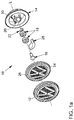
- FIGS. 1a and 1b show a rotatable decorative element 10 according to the invention, for a vehicle 12 (cf. Figure 2 ).
- Figure 1b includes an additional detail view D.
- FIG. 10 shows, in an exploded view, components comprised by the rotatable decorative element 10.
- Figure 1a is kept schematic, whereas the more detailed design of the components from the sectional view in Figure 1b can be found.
- the rotatable decorative element 10 comprises a housing 14, a shaft 16 and a bearing 18.
- the housing 14 is made of plastic, for example injection molded.
- the shaft 16 and the bearing 18 are components made of stainless steel.
- the housing 14 comprises a receiving space 20 for the bearing 18.
- the shaft 16 can be coupled to the bearing 18 along its longitudinal axis L and can be stored in the receiving space 20. It is then mounted on the housing 14 so as to be rotatable about the longitudinal axis L relative to the latter.
- a locking ring 22 with which the shaft 16 can be secured in the bearing 18. In the assembled state, the longitudinal axis L thus corresponds to the longitudinal axis L of all these components.
- the rotatable decorative element 10 comprises a decorative portion 24.
- the decorative section 24 comprises an injection molded part 26. Even if in FIG Figure 1a If an exploded view is selected for illustration, the injection-molded part 26 is connected to the shaft 16 by injection molding and is thus cantilevered on the shaft 16 (on this later with reference to FIG Figure 1b ). For this purpose, the shaft 16 is encapsulated with the injection molded part 26. Furthermore, a decorative element 10 ′ is provided on the decorative section 24. This is also connected to the injection-molded part 26 in that it is back-injected with the injection-molded part 26.
- the decorative section 24 furthermore comprises an eccentric weight 28, which is encapsulated by the injection-molded part 26.
- the decorative section 24, the shaft 16, the eccentric weight 28 and the decorative element 10 'thus form a composite component.
- Figure 1b received is a sectional view through the rotatable decorative element 10 from Figure 1a shows when this is configured.
- the cutting plane runs perpendicularly through the longitudinal axis L, with the longitudinal axis L lying completely in the cutting plane.
- the eccentric weight 28 causes the decorative section 24 to stand still when the housing 14 is rotated.
- the bearing 18 is inserted into the receiving space 20 and secured via a latching connection.
- the latching connection is implemented via a holding device 50 which is injected into the housing 14.
- the bearing 18 is enclosed in the housing 14 in an open, semi-encapsulated design. This is only possible because of the protection against dirt and water achieved by the invention, which will be discussed in more detail below.
- the housing 14 and the decorative section 24 form a cavity 30 due to their relative arrangement.
- the cavity 30 extends from the bearing 18 between the housing 14 and the decorative section 24 to the outside world 32.
- the housing 14 and the decorative section 24 are designed on one another in such a way that the cavity 30, in the radial direction R of the shaft 14, is separated from the outside world 32 by a plurality of material undercuts 34.
- the cavity 30 does not extend continuously linearly from the bearing 18 in the radial direction R to the outside world 32, but runs around the material undercuts 34 like a labyrinth.
- the material undercuts 34 each have a gradient 36, which will be explained below with reference to detail view D. Via the gradient 36, water, for example condensation water 38, which can form in the cavity 30 for climatic reasons, can be transported through the cavity 30 in the direction of the outside world 32, as shown.
- a gradient 36 at a material undercut 34 is shown on the basis of an auxiliary longitudinal axis HL, which is only used for illustration.
- Material undercut 34 is formed by the housing 14 with respect to the trim portion 24.
- the auxiliary longitudinal axis HL is oriented parallel to the longitudinal axis L.
- the gradient 36 can be inclined, for example, 3 ° with respect to the longitudinal axis L.
- further slopes 40 can be provided.
- Detailed view D shows that such a material undercut 34 is provided at a boundary 42 of the cavity 30 to the outside world 32.
- the material undercut 34 at the boundary 42 to the outside world 32 is designed in such a way that water, such as condensation water 38, takes an S-like course 44 when it is transported from the cavity 30 into the outside world 32. Exiting purely in the radial direction R is not possible. Conversely, no dirt or water, for example splash water, can enter the cavity 30 from the outside world 32 in the radial direction R.
- FIG Figure 2 shows a vehicle 12 according to the invention that has a rotatable decorative element 10 according to the invention, for example as in FIG Figure 1a and 1b shown includes.
- the vehicle 12 is a motor vehicle 46.
- the motor vehicle 46 comprises wheels with rims 48 which are provided with the rotatable decorative element 10.
Landscapes
- Engineering & Computer Science (AREA)
- Mechanical Engineering (AREA)
- Vehicle Interior And Exterior Ornaments, Soundproofing, And Insulation (AREA)
- Vehicle Waterproofing, Decoration, And Sanitation Devices (AREA)
Abstract
Description
- Die Erfindung betrifft ein drehbares Zierelement gemäß dem Oberbegriff des Patentanspruchs 1, ein drehbares Zierelement gemäß dem Oberbegriff des Patentanspruchs 3, ein drehbares Zierelement gemäß dem Oberbegriff des Patentanspruchs 7 sowie eine Fahrzeug gemäß dem Oberbegriff des Patentanspruchs 10.
- Drehbare Zierelemente sind dem Fachmann auf dem Gebiet von Fahrzeugen, beispielsweise Kraftfahrzeugen, bekannt. Derartige Zierelemente kommen im Bereich von Rädern von Fahrzeugen zum Einsatz und können beispielsweise ein Emblem, wie ein Herstellerlogo tragen. Ziel ist es dabei, das Zierelement auch bei sich drehendem Rad noch gut erkennbar zu orientieren, beziehungsweise die Drehung des Rades zu kompensieren.
- Aus dem Stand der Technik sind im Zusammenhang damit unterschiedliche technische Lösungen bekannt.
- So zeigt das US-amerikanische Patentdokument
US 5659989 A beispielsweise eine Radabdeckung mit einer drehbaren Scheibe, die ein exzentrisches Gewicht umfasst. - Weiterhin geht aus der europäischen Patentanmeldung
EP 2 607 096 A1 eine ähnliche Radnabenabdeckung hervor, bei der Schmutzpartikel fliehkraftgetrieben aus der Radnabenabdeckung ausgetragen werden können. - Der Erfindung liegt nun die Aufgabe zugrunde, eine verbesserte technische Lösung für ein drehbares Zierelement zu schaffen, die einen besseren Schutz vor Schmutz und Feuchtigkeit bietet und zugleich einfach aufgebaut ist.
- Die Aufgabe wird durch die Gegenstände der unabhängigen Patentansprüche 1, 3, 7 und 10 gelöst. Weitere bevorzugte Ausgestaltungen der Erfindung ergeben sich aus den übrigen, in den Unteransprüchen genannten Merkmalen.
- Gemäß der Erfindung besteht ein übergeordneter Gedanke darin, die Bereiche des technischen Systems, in die Schmutz oder Wasser eindringen können oder in denen sich Schmutz und Wasser ansammeln können, zu reduzieren.
- Vor diesem Hintergrund betrifft ein erster Aspekt der Erfindung ein drehbares Zierelement für ein Fahrzeug umfassend:
- ein Gehäuse;
- eine Welle, die an dem Gehäuse relativ zu diesem drehbar gelagert ist;
- einen Zierabschnitt, der das Zierelement aufweist und der fliegend an der Welle gelagert ist und sich dabei stirnseitig entlang des Gehäuses erstreckt; sowie
- ein exzentrisches Gewicht, das von dem Zierabschnitt umfasst ist.
- Gemäß der Erfindung ist vorgesehen, dass zumindest der Zierabschnitt und das exzentrische Gewicht ein Verbundbauteil bilden.
- Dadurch, dass das exzentrische Gewicht nicht wie bei konventionellen Lösungen lediglich in den Zierabschnitt eingesetzt wird, sondern mit diesem integral gefertigt wird, werden Montagespalte vorteilhaft vermieden. Zugleich wird die systematische Komplexität reduziert.
- In bevorzugter Ausgestaltung des drehbaren Zierelements der Erfindung ist vorgesehen, dass das Verbundbauteil den Zierabschnitt, die Welle und das exzentrische Gewicht umfasst.
- Somit werden zusätzliche Montagespalte vermieden. Ferner wird, neben einer weiteren Vereinfachung der Konstruktion erreicht, dass mehrere relativ zu dem Gehäuse rotierenden Elemente integriert sind. Somit lässt sich das System dynamisch besser auslegen.
- Es ist auch vom Gedanken der Erfindung umfasst, beispielsweise einen Innenring einer Lagerung der Welle in das Verbundbauteil zu integrieren, um so den Grad der Integration zu maximieren.
- Vor dem Hintergrund des eingangs erörterten übergeordneten Erfindungsgedankens betrifft ein weiterer Aspekt der Erfindung ein drehbares Zierelement für ein Fahrzeug, umfassend:
- ein Gehäuse;
- eine Welle, die an dem Gehäuse relativ zu diesem drehbar gelagert ist;
- einen Zierabschnitt, der das Zierelement aufweist und der fliegend an der Welle gelagert ist und sich dabei stirnseitig entlang des Gehäuses erstreckt; sowie
- ein exzentrisches Gewicht, das von dem Zierabschnitt umfasst ist.
- Gemäß der Erfindung ist vorgesehen, dass das Gehäuse und der Zierabschnitt derart aufeinander ausgelegt sind, dass eine zwischen diesen gebildete Kavität in radialer Richtung der Welle, durch wenigstens eine Materialhinterschneidung von der Außenwelt getrennt ist und die Materialhinterschneidung ein Gefälle aufweist, so dass Wasser durch die Kavität in Richtung der Außenwelt transportierbar ist.
- Mit anderen Worten ist, ausgehend von der Welle, somit keine geradlinige Verbindung durch die Kavität in die Außenwelt gegeben, da zumindest einmal das Gehäuse den Zierabschnitt hinterschneidet oder umgekehrt.
- Somit können Wasser oder Schmutz von der Außenwelt her nicht in die Kavität eindringen und in den Bereich der Lagerung gelangen. Zugleich kann in der Kavität befindliches Wasser, beispielsweise Kondenswasser, über das Gefälle sicher in die Außenwelt gelangen. Wenn sich das Gehäuse des drehbaren Zierelements mit dem Rad dreht, wird der Abtransport von Wasser durch Fliehkräfte unterstützt.
- In bevorzugter Ausgestaltung des drehbaren Zierelements der Erfindung ist vorgesehen, dass eine solche Materialhinterschneidung an einer Grenze der Kavität zur Außenwelt vorgesehen ist.
- An der Grenze zur Außenwelt ist die vorteilhafte Wirkung der Materialhinterschneidung besonders groß, da so der gesamte weiter innen liegende Bereich der Kavität geschützt wird.
- In weiter bevorzugter Ausgestaltung des drehbaren Zierelements der Erfindung ist vorgesehen, dass die Materialhinterschneidung an der Grenze zur Außenwelt derart gestaltet ist, dass das Wasser, wenn dieses aus der Kavität in die Außenwelt transportiert wird, einen S-artigen Verlauf nimmt.
- Mit anderen Worten muss das Wasser aufgrund der Materialhinterschneidung seine Flussrichtung zumindest zweimal ändern, um aus der Kavität über die Grenze radial in die Außenwelt austreten zu können. Reinexemplarisch kann das Wasser zunächst radial in der Kavität fließen, kann die Flussrichtung sich dann in Richtung einer Längsrichtung der Welle verlagern und kann dann wieder radial bezogen auf die Welle fließen beziehungsweise aus der Kavität austreten.
- Auf diese Weise ist die Materialhinterschneidung besonders einfach und effektiv realisierbar.
- In weiter bevorzugter Ausgestaltung des drehbaren Zierelements der Erfindung ist vorgesehen, dass, ausgehend von der Welle in Richtung einer Grenze der Kavität zur Außenwelt, entlang der Kavität wenigstens eine weitere Materialhinterschneidung vorgesehen ist, die ein Gefälle aufweist, so dass Wasser durch die Kavität in Richtung der Außenwelt transportierbar ist.
- Je mehr solcher Materialhinterschneidungen vorgesehen sind, umso besser kann das Wasser radial auch über größere Distanzen abtransportiert werden, wobei der Bauraum des drehbaren Zierelements in Längsrichtung der Welle gering gehalten werden kann.
- Vor dem Hintergrund des eingangs erörterten übergeordneten Erfindungsgedankens betrifft ein weiterer Aspekt der Erfindung ein drehbares Zierelement für ein Fahrzeug, umfassend:
- ein Gehäuse;
- eine Welle, die an dem Gehäuse relativ zu diesem drehbar gelagert ist;
- einen Zierabschnitt, der das Zierelement aufweist und der fliegend an der Welle gelagert ist und sich dabei stirnseitig entlang des Gehäuses erstreckt; sowie
- ein exzentrisches Gewicht, das von dem Zierabschnitt umfasst ist.
- Gemäß der Erfindung ist vorgesehen, dass zumindest der Zierabschnitt und das exzentrische Gewicht ein Verbundbauteil bilden und dass das Gehäuse und das Verbundbauteil derart aufeinander ausgelegt sind, dass eine zwischen diesen gebildete Kavität, in radialer Richtung der Welle, durch wenigstens eine Materialhinterschneidung von der Außenwelt getrennt ist und die Materialhinterschneidung ein Gefälle aufweist, so dass Wasser durch die Kavität in Richtung der Außenwelt transportierbar ist.
- Mit anderen Worten betrifft dies also ein drehbares Zierelement, das die Merkmale der vorangehend beschriebenen drehbaren Zierelemente der Erfindung vereint.
- Entsprechend sind die offenbarten Weiterbildungen der vorangehend beschriebenen drehbaren Zierelemente der Erfindung auch auf dieses drehbare Zierelemente der Erfindung übertragbar.
- In weiter bevorzugter Ausgestaltung eines der drehbaren Zierelemente der Erfindung ist vorgesehen, dass der Zierabschnitt ein Spritzgussteil umfasst, das durch Spritzgießen mit zumindest einem der folgenden Elemente verbunden ist: mit dem exzentrischen Gewicht; mit der Welle; abschnittsweise mit einer Lagerung der Welle; mit dem Zierelement.
- Die Herstellung des Zierabschnitts in dem Spritzgießverfahren ist besonders vorteilhaft mit Hinblick auf Aufwand und Flexibilität sowie die Vermeidung von Montagespalten. Vorzugsweise werden die Elemente derart eingespritzt, dass sie nicht mehr zerstörungsfrei lösbar sind, um die Verbindung so dicht wie möglich zu gestalten.
- Vorzugsweise handelt es sich bei dem Spritzgussteil um ein Kunststoffteil. Das Zierelement kann vorteilhaft direkt mit dem Spritzgussteil hinterspritzt werden. Das Zierelement kann beispielsweise Aluminium umfassen. Für die Welle, die Lagerung und das exzentrisches Gewicht wird Edelstahl als Werkstoff bevorzugt. Für das Gehäuse wird Kunststoff als Werkstoff bevorzugt.
- Da die drehbaren Zierelemente der Erfindung über einen besonders guten Schutz vor Schmutz und Feuchtigkeit verfügen, bieten sie sich insbesondere zur Realisierung von eingebetteten elektrischen Funktionen an. Beispielsweise können so auch zusätzlich beleuchtete Zierelemente realisiert werden. Beispielsweise können Magnete und Spulen vorgesehen werden, um die relative Bewegung zwischen Gehäuse und Zierabschnitt für elektrische Induktion nutzen. Beispielsweise können LEDs oder auch Elektrolumineszensfolien verwendet werden, um das Zierelement zum Leuchten zu bringen oder zu beleuchten.
- Ein weiterer Aspekt der Erfindung betrifft ein Fahrzeug, vorzugsweise ein Kraftfahrzeug, umfassend ein erfindungsgemäßes drehbares Zierelement gemäß der vorhergehenden Beschreibung.
- Vorzugsweise ist das drehbare Zierelement an einem Rad des Fahrzeugs, vorzugsweise einer Felge, vorgesehen.
- Die verschiedenen in dieser Anmeldung genannten Ausführungsformen der Erfindung sind, sofern im Einzelfall nicht anders ausgeführt, mit Vorteil miteinander kombinierbar.
- Die Erfindung wird nachfolgend in Ausführungsbeispielen anhand der zugehörigen Zeichnungen erläutert. Es zeigen:
- Figuren 1a/1b
- ein erfindungsgemäßes drehbares Zierelement in verschiedenen Ansichten; und
- Figur 2
- ein erfindungsgemäßes Fahrzeug.
- Die
Figuren 1a und1b zeigen ein drehbares Zierelement 10 gemäß der Erfindung, für ein Fahrzeug 12 (vergleicheFigur 2 ).Figur 1b umfasst eine zusätzliche Detailansichten D. -
Figur 1a zeigt in einer Explosionsansicht Komponenten, die von dem drehbaren Zierelement 10 umfasst sind.Figur 1a ist dabei schematisch gehalten, wohingegen die genauere Gestaltung der Komponenten aus der Schnittansicht inFigur 1b zu entnehmen ist. - Zunächst ist in
Figur 1a ersichtlich, dass das drehbare Zierelement 10 ein Gehäuse 14, eine Welle 16 und eine Lagerung 18 umfasst. Das Gehäuse 14 ist aus Kunststoff hergestellt, beispielsweise spritzgegossen. Bei der Welle 16 und der Lagerung 18 handelt es sich um Komponenten aus Edelstahl. Das Gehäuse 14 umfasst einen Aufnahmeraum 20 für die Lagerung 18. Die Welle 16 ist entlang ihrer Längsachse L mit der Lagerung 18 koppelbar und in dem Aufnahmeraum 20 lagerbar. Sie ist dann an dem Gehäuse 14 relativ zu diesem um die Längsachse L drehbar gelagert. Gezeigt ist ferner ein Sicherungsring 22, mit dem die Welle 16 in der Lagerung 18 sicherbar ist. Im montierten Zustand entspricht die Längsachse L somit der Längsachse L aller dieser Komponenten. - Weiterhin zeigt
Figur 1a , dass das drehbare Zierelement 10 einen Zierabschnitt 24 umfasst. Der Zierabschnitt 24 umfasst ein Spritzgussteil 26. Auch wenn inFigur 1a zur Veranschaulichung eine Explosionsdarstellung gewählt ist, ist das Spritzgussteil 26 durch Spritzgießen mit der Welle 16 verbunden und somit fliegend an der Welle 16 gelagert (dazu später in Bezug aufFigur 1b ). Die Welle 16 ist dafür mit dem Spritzgussteil 26 umspritzt. Ferner ist an dem Zierabschnitt 24 ein Zierelement 10' vorgesehen. Dieses ist ebenfalls mit dem Spritzgussteil 26 verbunden, indem es mit dem Spritzgussteil 26 hinterspritzt ist. Das Zierabschnitt 24 umfasst weiterhin ein exzentrisches Gewicht 28, das von dem Spritzgussteil 26 umspritzt ist. Somit bilden der Zierabschnitt 24, die Welle 16, das exzentrische Gewicht 28 und das Zierelement 10' ein Verbundbauteil. - Zur weiteren Erläuterung wird auf
Figur 1b eingegangen, die eine Schnittansicht durch das drehbare Zierelement 10 ausFigur 1a darstellt, wenn dieses zusammengebaut ist. Die Schnittebene verläuft dabei senkrecht durch die Längsachse L, wobei die Längsachse L vollständig in der Schnittebene liegt. - Aus
Figur 1b ist ersichtlich, dass der Zierabschnitt 24 sich stirnseitig entlang des Gehäuses 14 erstreckt und dabei über die Lagerung 18 relativ zu diesem um die Längsachse L drehbar ist. - Das exzentrische Gewicht 28 bewirkt aufgrund der Schwerkraft, dass der Zierabschnitt 24 stillsteht, wenn das Gehäuse 14 gedreht wird.
- Die Lagerung 18 ist in den Aufnahmeraum 20 eingesetzt und über eine Rastverbindung gesichert. Die Rastverbindung wird über eine Haltevorrichtung 50 realisiert, die in das Gehäuse 14 eingespritzt ist. Die Lagerung 18 ist in einer offenen, halbgekapselten Bauweise in dem Gehäuse 14 eingefasst. Dies ist nur auf Grund des durch die Erfindung erreichten Schutzes vor Schmutz und Wasser möglich, worauf im Folgenden noch näher eingegangen wird.
- Das Gehäuse 14 und der Zierabschnitt 24 bilden auf Grund ihrer relativen Anordnung eine Kavität 30 aus. Die Kavität 30 erstreckt sich von der Lagerung 18 zwischen dem Gehäuse 14 und dem Zierabschnitt 24 bis hin zur Außenwelt 32.
- Dabei sind das Gehäuse 14 und der Zierabschnitt 24 derart aufeinander ausgelegt, dass die Kavität 30, in radialer Richtung R der Welle 14, durch eine Mehrzahl von Materialhinterschneidungen 34 von der Außenwelt 32 getrennt ist. Mit anderen Worten erstreckt sich Kavität 30 von der Lagerung 18 in radialer Richtung R nicht durchgehend linear bis zur Außenwelt 32, sondern verläuft um die Materialhinterschneidungen 34 labyrinthartig herum. Die Materialhinterschneidungen 34 weisen dabei jeweils ein Gefälle 36 auf, was im Folgenden in Bezug auf Detailansicht D noch erläutert wird. Über das Gefälle 36 kann Wasser, beispielsweise Kondenswasser 38, das sich aus klimatischen Gründen in der Kavität 30 bilden kann, wie dargestellt durch die Kavität 30 in Richtung der Außenwelt 32 transportiert werden.
- In Detailansicht D ist ein Detailbereich gezeigt, gemäß der Kennzeichnung D in
Figur 1b . - Dort ist anhand einer Hilfslängsachse HL, die nur der Illustration dient, ein Gefälle 36 an einer Materialhinterschneidung 34 gezeigt. Materialhinterschneidung 34 wird von dem Gehäuse 14 in Bezug auf den Zierabschnitt 24 gebildet. Die Hilfslängsachse HL ist parallel zur Längsachse L orientiert. Das Gefälle 36 kann beispielsweise 3° gegenüber der Längsachse L geneigt sein. Um den Abtransport von beispielsweise Kondenswasser 38 zu unterstützen, können weitere Schrägen 40 vorgesehen sein.
- Auch wenn vorliegend die Materialhinterschneidungen 34 mit gleichen Bezugszeichen versehen sind, so können sie im Detail doch nach Ermessen des Fachmannes ausgestaltet werden, der sich dabei nach dem hierin offenbarten Sinn und Zweck der Materialhinterschneidung 34 richtet.
- So zeigt Detailansicht D, dass eine solche Materialhinterschneidung 34 an einer Grenze 42 der Kavität 30 zur Außenwelt 32 vorgesehen ist. Die Materialhinterschneidung 34 an der Grenze 42 zur Außenwelt 32 ist derart gestaltet, dass Wasser wie Kondenswasser 38, wenn dieses aus der Kavität 30 in die Außenwelt 32 transportiert wird, einen S-artigen Verlauf 44 nimmt. Ein Austritt rein in radialer Richtung R ist nicht möglich. Im Umkehrschluss kann somit aus der Außenwelt 32 in radialer Richtung R auch kein Schmutz oder Wasser, beispielsweise Spritzwasser, in die Kavität 30 eintreten.
-
Figur 2 zeigt ein erfindungsgemäßes Fahrzeug 12, dass ein erfindungsgemäßes drehbares Zierelement 10, beispielsweise wie inFigur 1a und1b gezeigt, umfasst. - Bei dem Fahrzeug 12 handelt es sich um ein Kraftfahrzeug 46. Das Kraftfahrzeug 46 umfasst Räder mit Felgen 48, die mit dem drehbaren Zierelement 10 versehen sind.
-
- 10
- drehbares Zierelement
- 10'
- Zierelement
- 12
- Fahrzeug
- 14
- Gehäuse
- 16
- Welle
- 18
- Lagerung
- 20
- Aufnahmeraum
- 22
- Sicherungsring
- 24
- Zierabschnitt
- 26
- Spritzgussteil
- 28
- exzentrisches Gewicht
- 30
- Kavität
- 32
- Außenwelt
- 34
- Materialhinterschneidung
- 36
- Gefälle
- 38
- Kondenswasser
- 40
- Schräge
- 42
- Grenze
- 44
- S-artiger Verlauf
- 46
- Kraftfahrzeug
- 48
- Felge
- 50
- Haltevorrichtung
- HL
- Hilfslängsachse
- L
- Längsachse
- R
- radiale Richtung
Claims (10)
- Drehbares Zierelement (10) für ein Fahrzeug (12), umfassend:- ein Gehäuse (14);- eine Welle (16), die an dem Gehäuse relativ zu diesem drehbar gelagert ist;- einen Zierabschnitt (24), der ein Zierelement (10') aufweist und der fliegend an der Welle gelagert ist und sich dabei stirnseitig entlang des Gehäuses erstreckt;- ein exzentrisches Gewicht (28), das von dem Zierabschnitt umfasst ist,dadurch gekennzeichnet, dass
zumindest der Zierabschnitt und das exzentrische Gewicht ein Verbundbauteil bilden. - Drehbares Zierelement nach Anspruch 1, dadurch gekennzeichnet, dass das Verbundbauteil den Zierabschnitt, die Welle und das exzentrische Gewicht umfasst.
- Drehbares Zierelement (10) für ein Fahrzeug (12), umfassend:- ein Gehäuse (14);- eine Welle (16), die an dem Gehäuse relativ zu diesem drehbar gelagert ist;- einen Zierabschnitt (24), der ein Zierelement (10') aufweist und der fliegend an der Welle gelagert ist und sich dabei stirnseitig entlang des Gehäuses erstreckt;- ein exzentrisches Gewicht (28), das von dem Zierabschnitt umfasst ist,dadurch gekennzeichnet, dass
das Gehäuse und der Zierabschnitt derart aufeinander ausgelegt sind, dass eine zwischen diesen gebildete Kavität (30), in radialer Richtung (R) der Welle, durch wenigstens eine Materialhinterschneidung (34) von der Außenwelt (32) getrennt ist und die Materialhinterschneidung ein Gefälle (36) aufweist, so dass Wasser (38) durch die Kavität in Richtung der Außenwelt transportierbar ist. - Drehbares Zierelement nach Anspruch 3, dadurch gekennzeichnet, dass eine solche Materialhinterschneidung an einer Grenze (42) der Kavität zur Außenwelt vorgesehen ist.
- Drehbares Zierelement nach Anspruch 4, dadurch gekennzeichnet, dass die Materialhinterschneidung an der Grenze zur Außenwelt derart gestaltet ist, dass das Wasser, wenn dieses aus der Kavität in die Außenwelt transportiert wird, einen S-artigen Verlauf (44) nimmt.
- Drehbares Zierelement nach einem der Ansprüche 3 bis 5, dadurch gekennzeichnet, dass, ausgehend von der Welle in Richtung einer Grenze (42) der Kavität zur Außenwelt, entlang der Kavität wenigstens eine weitere Materialhinterschneidung (34) vorgesehen ist, die ein Gefälle (36) aufweist, so dass Wasser (38) durch die Kavität in Richtung der Außenwelt transportierbar ist.
- Drehbares Zierelement (10) für ein Fahrzeug (12), umfassend:- ein Gehäuse (14);- eine Welle (16), die an dem Gehäuse relativ zu diesem drehbar gelagert ist;- einen Zierabschnitt (24), der ein Zierelement (10') aufweist und der fliegend an der Welle gelagert ist und sich dabei stirnseitig entlang des Gehäuses erstreckt;- ein exzentrisches Gewicht (28), das von dem Zierabschnitt umfasst ist,dadurch gekennzeichnet, dass
zumindest der Zierabschnitt und das exzentrische Gewicht ein Verbundbauteil bilden und dass das Gehäuse und das Verbundbauteil derart aufeinander ausgelegt sind, dass eine zwischen diesen gebildete Kavität (30), in radialer Richtung (R) der Welle, durch wenigstens eine Materialhinterschneidung (34) von der Außenwelt (32) getrennt ist und die Materialhinterschneidung ein Gefälle (36) aufweist, so dass Wasser (38) durch die Kavität in Richtung der Außenwelt transportierbar ist. - Drehbares Zierelement nach Anspruch 7, dadurch gekennzeichnet, dass das Zierelement (10) weiterhin die Merkmale von wenigstens einem der Ansprüche 2 oder 4 bis 6 umfasst.
- Drehbares Zierelement nach einem der Ansprüche 1 bis 8, dadurch gekennzeichnet, dass der Zierabschnitt ein Spritzgussteil (26) umfasst, das durch Spritzgießen mit zumindest einem der folgenden Elemente verbunden ist: mit dem exzentrischen Gewicht; mit der Welle; abschnittsweise mit einer Lagerung (18) der Welle; mit dem Zierelement (10').
- Fahrzeug (12), umfassend ein drehbares Zierelement (10) nach einem der vorhergehenden Ansprüche.
Applications Claiming Priority (1)
| Application Number | Priority Date | Filing Date | Title |
|---|---|---|---|
| DE102019202507.2A DE102019202507B4 (de) | 2019-02-25 | 2019-02-25 | Drehbares Zierelement |
Publications (2)
| Publication Number | Publication Date |
|---|---|
| EP3698982A1 true EP3698982A1 (de) | 2020-08-26 |
| EP3698982B1 EP3698982B1 (de) | 2023-05-24 |
Family
ID=69174378
Family Applications (1)
| Application Number | Title | Priority Date | Filing Date |
|---|---|---|---|
| EP20152178.8A Active EP3698982B1 (de) | 2019-02-25 | 2020-01-16 | Drehbares zierelement |
Country Status (2)
| Country | Link |
|---|---|
| EP (1) | EP3698982B1 (de) |
| DE (1) | DE102019202507B4 (de) |
Cited By (1)
| Publication number | Priority date | Publication date | Assignee | Title |
|---|---|---|---|---|
| DE102023000448A1 (de) | 2023-02-13 | 2023-08-10 | Mercedes-Benz Group AG | Radnabenabdeckung für ein Fahrzeug |
Citations (7)
| Publication number | Priority date | Publication date | Assignee | Title |
|---|---|---|---|---|
| DE8807263U1 (de) * | 1987-08-18 | 1988-12-15 | Jang, Chan Soo, Seoul | Automobil-Radkappe |
| US5659989A (en) | 1994-07-13 | 1997-08-26 | Hsiao; Leslie | Wheel cover |
| EP2380748A1 (de) * | 2010-04-26 | 2011-10-26 | Chih-Hao Yin | Drehende Radabdeckung |
| EP2607096A1 (de) | 2011-12-22 | 2013-06-26 | Heinz Wilhelm | Radnabenabdeckung |
| EP3132946A1 (de) * | 2014-04-14 | 2017-02-22 | Yoo, Chung Sup | Bildplatte für drehrad und drehrad damit |
| US20180022149A1 (en) * | 2015-03-27 | 2018-01-25 | Bosswell Korea Inc. | Light emitting device for automobile wheel |
| EP3628508A1 (de) * | 2018-09-27 | 2020-04-01 | ROTECH Antriebselemente GmbH | Radnabenabdeckung |
Family Cites Families (4)
| Publication number | Priority date | Publication date | Assignee | Title |
|---|---|---|---|---|
| US2014058A (en) * | 1934-05-01 | 1935-09-10 | Tonai Hideo | Hub cap |
| GB0300553D0 (en) * | 2003-01-10 | 2003-02-12 | Bentley Motors Ltd | Apparatus for maintaining the orientation of a badge or other insignia |
| JP5325064B2 (ja) * | 2009-09-29 | 2013-10-23 | ダイハツ工業株式会社 | 車輪支持装置 |
| US9555665B2 (en) * | 2013-09-09 | 2017-01-31 | Michael Burton | Bicycle spinner mounting |
-
2019
- 2019-02-25 DE DE102019202507.2A patent/DE102019202507B4/de active Active
-
2020
- 2020-01-16 EP EP20152178.8A patent/EP3698982B1/de active Active
Patent Citations (7)
| Publication number | Priority date | Publication date | Assignee | Title |
|---|---|---|---|---|
| DE8807263U1 (de) * | 1987-08-18 | 1988-12-15 | Jang, Chan Soo, Seoul | Automobil-Radkappe |
| US5659989A (en) | 1994-07-13 | 1997-08-26 | Hsiao; Leslie | Wheel cover |
| EP2380748A1 (de) * | 2010-04-26 | 2011-10-26 | Chih-Hao Yin | Drehende Radabdeckung |
| EP2607096A1 (de) | 2011-12-22 | 2013-06-26 | Heinz Wilhelm | Radnabenabdeckung |
| EP3132946A1 (de) * | 2014-04-14 | 2017-02-22 | Yoo, Chung Sup | Bildplatte für drehrad und drehrad damit |
| US20180022149A1 (en) * | 2015-03-27 | 2018-01-25 | Bosswell Korea Inc. | Light emitting device for automobile wheel |
| EP3628508A1 (de) * | 2018-09-27 | 2020-04-01 | ROTECH Antriebselemente GmbH | Radnabenabdeckung |
Cited By (2)
| Publication number | Priority date | Publication date | Assignee | Title |
|---|---|---|---|---|
| DE102023000448A1 (de) | 2023-02-13 | 2023-08-10 | Mercedes-Benz Group AG | Radnabenabdeckung für ein Fahrzeug |
| DE102023000448B4 (de) | 2023-02-13 | 2024-06-06 | Mercedes-Benz Group AG | Radnabenabdeckung für ein Fahrzeug |
Also Published As
| Publication number | Publication date |
|---|---|
| EP3698982B1 (de) | 2023-05-24 |
| DE102019202507B4 (de) | 2021-02-18 |
| DE102019202507A1 (de) | 2020-08-27 |
Similar Documents
| Publication | Publication Date | Title |
|---|---|---|
| EP1609996B1 (de) | Laufrad, insbesondere für einen Axialventilator | |
| DE2046486C3 (de) | Schaufelrad für Lüfter | |
| DE102013105524B4 (de) | Radiallüfter | |
| EP2401518B1 (de) | Innenbelüftete bremsscheibe | |
| WO2011038884A1 (de) | Diagonalventilator | |
| WO2006136585A1 (de) | Rotor mit lüfterrad für einen elektronisch kommutierten elektromotor | |
| EP4073389B1 (de) | Lüfterrad für einen rotor und elektrische maschine | |
| WO2016095915A1 (de) | Axialventilator | |
| EP3698982B1 (de) | Drehbares zierelement | |
| DE69601959T2 (de) | Montagevorrichtung für Rad und mit Laufrädern versehener, mit solcher Vorrichtung ausgerüsteter, Müllsammelbehälter | |
| EP1816729A2 (de) | Elektromotor | |
| DE102011088644A1 (de) | Schmiervorrichtung für ein Getriebe sowie elektrische Antriebseinrichtung mit der Schmiervorrichtung | |
| DE202010011378U1 (de) | Ventilator-Laufrad | |
| WO2010034567A1 (de) | Elektrische maschine mit einer verdrehsicherung für ein stromkabel | |
| EP1503479B1 (de) | Aussenläufermotor mit Dichtung | |
| DE102014216501A1 (de) | Bürstendichtung mit Förderwirkung | |
| EP1258636B1 (de) | Lüfterrad sowie Lüfter, insbesondere Radiallüfter | |
| DE19544997C1 (de) | Drehsensor | |
| DE102013221119A1 (de) | Luftschaufelrad zum Transport von Luft mit einem Luftlager und Radialverdichter mit einem Luftschaufelrad | |
| CH672700A5 (de) | ||
| DE102009026984A1 (de) | Anordnung mit einem Gehäuse und einem Deckel | |
| DE102023122243A1 (de) | Wellenfeder für eine Wellenlageranordnung, Gehäuse für eine Wellenlageranordnung, Wellenlageranordnung, Maschine und Kraftfahrzeug | |
| DE102015004084A1 (de) | Elektrischer Antriebsmotor, insbesondere Drehtellerantrieb | |
| DE202012001225U1 (de) | Pumpenaggregat | |
| EP0640767A1 (de) | Pumpe für Flüssigkeiten |
Legal Events
| Date | Code | Title | Description |
|---|---|---|---|
| PUAI | Public reference made under article 153(3) epc to a published international application that has entered the european phase |
Free format text: ORIGINAL CODE: 0009012 |
|
| STAA | Information on the status of an ep patent application or granted ep patent |
Free format text: STATUS: THE APPLICATION HAS BEEN PUBLISHED |
|
| AK | Designated contracting states |
Kind code of ref document: A1 Designated state(s): AL AT BE BG CH CY CZ DE DK EE ES FI FR GB GR HR HU IE IS IT LI LT LU LV MC MK MT NL NO PL PT RO RS SE SI SK SM TR |
|
| AX | Request for extension of the european patent |
Extension state: BA ME |
|
| STAA | Information on the status of an ep patent application or granted ep patent |
Free format text: STATUS: REQUEST FOR EXAMINATION WAS MADE |
|
| 17P | Request for examination filed |
Effective date: 20210226 |
|
| RBV | Designated contracting states (corrected) |
Designated state(s): AL AT BE BG CH CY CZ DE DK EE ES FI FR GB GR HR HU IE IS IT LI LT LU LV MC MK MT NL NO PL PT RO RS SE SI SK SM TR |
|
| GRAP | Despatch of communication of intention to grant a patent |
Free format text: ORIGINAL CODE: EPIDOSNIGR1 |
|
| STAA | Information on the status of an ep patent application or granted ep patent |
Free format text: STATUS: GRANT OF PATENT IS INTENDED |
|
| INTG | Intention to grant announced |
Effective date: 20230309 |
|
| GRAS | Grant fee paid |
Free format text: ORIGINAL CODE: EPIDOSNIGR3 |
|
| GRAA | (expected) grant |
Free format text: ORIGINAL CODE: 0009210 |
|
| STAA | Information on the status of an ep patent application or granted ep patent |
Free format text: STATUS: THE PATENT HAS BEEN GRANTED |
|
| AK | Designated contracting states |
Kind code of ref document: B1 Designated state(s): AL AT BE BG CH CY CZ DE DK EE ES FI FR GB GR HR HU IE IS IT LI LT LU LV MC MK MT NL NO PL PT RO RS SE SI SK SM TR |
|
| REG | Reference to a national code |
Ref country code: GB Ref legal event code: FG4D Free format text: NOT ENGLISH |
|
| REG | Reference to a national code |
Ref country code: CH Ref legal event code: EP |
|
| REG | Reference to a national code |
Ref country code: DE Ref legal event code: R096 Ref document number: 502020003305 Country of ref document: DE |
|
| REG | Reference to a national code |
Ref country code: AT Ref legal event code: REF Ref document number: 1569294 Country of ref document: AT Kind code of ref document: T Effective date: 20230615 |
|
| REG | Reference to a national code |
Ref country code: IE Ref legal event code: FG4D Free format text: LANGUAGE OF EP DOCUMENT: GERMAN |
|
| REG | Reference to a national code |
Ref country code: LT Ref legal event code: MG9D |
|
| REG | Reference to a national code |
Ref country code: NL Ref legal event code: MP Effective date: 20230524 |
|
| PG25 | Lapsed in a contracting state [announced via postgrant information from national office to epo] |
Ref country code: SE Free format text: LAPSE BECAUSE OF FAILURE TO SUBMIT A TRANSLATION OF THE DESCRIPTION OR TO PAY THE FEE WITHIN THE PRESCRIBED TIME-LIMIT Effective date: 20230524 Ref country code: PT Free format text: LAPSE BECAUSE OF FAILURE TO SUBMIT A TRANSLATION OF THE DESCRIPTION OR TO PAY THE FEE WITHIN THE PRESCRIBED TIME-LIMIT Effective date: 20230925 Ref country code: NO Free format text: LAPSE BECAUSE OF FAILURE TO SUBMIT A TRANSLATION OF THE DESCRIPTION OR TO PAY THE FEE WITHIN THE PRESCRIBED TIME-LIMIT Effective date: 20230824 Ref country code: NL Free format text: LAPSE BECAUSE OF FAILURE TO SUBMIT A TRANSLATION OF THE DESCRIPTION OR TO PAY THE FEE WITHIN THE PRESCRIBED TIME-LIMIT Effective date: 20230524 Ref country code: ES Free format text: LAPSE BECAUSE OF FAILURE TO SUBMIT A TRANSLATION OF THE DESCRIPTION OR TO PAY THE FEE WITHIN THE PRESCRIBED TIME-LIMIT Effective date: 20230524 |
|
| PG25 | Lapsed in a contracting state [announced via postgrant information from national office to epo] |
Ref country code: RS Free format text: LAPSE BECAUSE OF FAILURE TO SUBMIT A TRANSLATION OF THE DESCRIPTION OR TO PAY THE FEE WITHIN THE PRESCRIBED TIME-LIMIT Effective date: 20230524 Ref country code: PL Free format text: LAPSE BECAUSE OF FAILURE TO SUBMIT A TRANSLATION OF THE DESCRIPTION OR TO PAY THE FEE WITHIN THE PRESCRIBED TIME-LIMIT Effective date: 20230524 Ref country code: LV Free format text: LAPSE BECAUSE OF FAILURE TO SUBMIT A TRANSLATION OF THE DESCRIPTION OR TO PAY THE FEE WITHIN THE PRESCRIBED TIME-LIMIT Effective date: 20230524 Ref country code: LT Free format text: LAPSE BECAUSE OF FAILURE TO SUBMIT A TRANSLATION OF THE DESCRIPTION OR TO PAY THE FEE WITHIN THE PRESCRIBED TIME-LIMIT Effective date: 20230524 Ref country code: IS Free format text: LAPSE BECAUSE OF FAILURE TO SUBMIT A TRANSLATION OF THE DESCRIPTION OR TO PAY THE FEE WITHIN THE PRESCRIBED TIME-LIMIT Effective date: 20230924 Ref country code: HR Free format text: LAPSE BECAUSE OF FAILURE TO SUBMIT A TRANSLATION OF THE DESCRIPTION OR TO PAY THE FEE WITHIN THE PRESCRIBED TIME-LIMIT Effective date: 20230524 Ref country code: GR Free format text: LAPSE BECAUSE OF FAILURE TO SUBMIT A TRANSLATION OF THE DESCRIPTION OR TO PAY THE FEE WITHIN THE PRESCRIBED TIME-LIMIT Effective date: 20230825 |
|
| PG25 | Lapsed in a contracting state [announced via postgrant information from national office to epo] |
Ref country code: FI Free format text: LAPSE BECAUSE OF FAILURE TO SUBMIT A TRANSLATION OF THE DESCRIPTION OR TO PAY THE FEE WITHIN THE PRESCRIBED TIME-LIMIT Effective date: 20230524 |
|
| PG25 | Lapsed in a contracting state [announced via postgrant information from national office to epo] |
Ref country code: SK Free format text: LAPSE BECAUSE OF FAILURE TO SUBMIT A TRANSLATION OF THE DESCRIPTION OR TO PAY THE FEE WITHIN THE PRESCRIBED TIME-LIMIT Effective date: 20230524 |
|
| PG25 | Lapsed in a contracting state [announced via postgrant information from national office to epo] |
Ref country code: SM Free format text: LAPSE BECAUSE OF FAILURE TO SUBMIT A TRANSLATION OF THE DESCRIPTION OR TO PAY THE FEE WITHIN THE PRESCRIBED TIME-LIMIT Effective date: 20230524 Ref country code: SK Free format text: LAPSE BECAUSE OF FAILURE TO SUBMIT A TRANSLATION OF THE DESCRIPTION OR TO PAY THE FEE WITHIN THE PRESCRIBED TIME-LIMIT Effective date: 20230524 Ref country code: RO Free format text: LAPSE BECAUSE OF FAILURE TO SUBMIT A TRANSLATION OF THE DESCRIPTION OR TO PAY THE FEE WITHIN THE PRESCRIBED TIME-LIMIT Effective date: 20230524 Ref country code: EE Free format text: LAPSE BECAUSE OF FAILURE TO SUBMIT A TRANSLATION OF THE DESCRIPTION OR TO PAY THE FEE WITHIN THE PRESCRIBED TIME-LIMIT Effective date: 20230524 Ref country code: DK Free format text: LAPSE BECAUSE OF FAILURE TO SUBMIT A TRANSLATION OF THE DESCRIPTION OR TO PAY THE FEE WITHIN THE PRESCRIBED TIME-LIMIT Effective date: 20230524 Ref country code: CZ Free format text: LAPSE BECAUSE OF FAILURE TO SUBMIT A TRANSLATION OF THE DESCRIPTION OR TO PAY THE FEE WITHIN THE PRESCRIBED TIME-LIMIT Effective date: 20230524 |
|
| REG | Reference to a national code |
Ref country code: DE Ref legal event code: R097 Ref document number: 502020003305 Country of ref document: DE |
|
| PLBE | No opposition filed within time limit |
Free format text: ORIGINAL CODE: 0009261 |
|
| STAA | Information on the status of an ep patent application or granted ep patent |
Free format text: STATUS: NO OPPOSITION FILED WITHIN TIME LIMIT |
|
| 26N | No opposition filed |
Effective date: 20240227 |
|
| PG25 | Lapsed in a contracting state [announced via postgrant information from national office to epo] |
Ref country code: SI Free format text: LAPSE BECAUSE OF FAILURE TO SUBMIT A TRANSLATION OF THE DESCRIPTION OR TO PAY THE FEE WITHIN THE PRESCRIBED TIME-LIMIT Effective date: 20230524 |
|
| PG25 | Lapsed in a contracting state [announced via postgrant information from national office to epo] |
Ref country code: SI Free format text: LAPSE BECAUSE OF FAILURE TO SUBMIT A TRANSLATION OF THE DESCRIPTION OR TO PAY THE FEE WITHIN THE PRESCRIBED TIME-LIMIT Effective date: 20230524 Ref country code: IT Free format text: LAPSE BECAUSE OF FAILURE TO SUBMIT A TRANSLATION OF THE DESCRIPTION OR TO PAY THE FEE WITHIN THE PRESCRIBED TIME-LIMIT Effective date: 20230524 |
|
| PG25 | Lapsed in a contracting state [announced via postgrant information from national office to epo] |
Ref country code: MC Free format text: LAPSE BECAUSE OF FAILURE TO SUBMIT A TRANSLATION OF THE DESCRIPTION OR TO PAY THE FEE WITHIN THE PRESCRIBED TIME-LIMIT Effective date: 20230524 |
|
| PG25 | Lapsed in a contracting state [announced via postgrant information from national office to epo] |
Ref country code: MC Free format text: LAPSE BECAUSE OF FAILURE TO SUBMIT A TRANSLATION OF THE DESCRIPTION OR TO PAY THE FEE WITHIN THE PRESCRIBED TIME-LIMIT Effective date: 20230524 |
|
| REG | Reference to a national code |
Ref country code: CH Ref legal event code: PL |
|
| PG25 | Lapsed in a contracting state [announced via postgrant information from national office to epo] |
Ref country code: LU Free format text: LAPSE BECAUSE OF NON-PAYMENT OF DUE FEES Effective date: 20240116 |
|
| PG25 | Lapsed in a contracting state [announced via postgrant information from national office to epo] |
Ref country code: LU Free format text: LAPSE BECAUSE OF NON-PAYMENT OF DUE FEES Effective date: 20240116 |
|
| PG25 | Lapsed in a contracting state [announced via postgrant information from national office to epo] |
Ref country code: BE Free format text: LAPSE BECAUSE OF NON-PAYMENT OF DUE FEES Effective date: 20240131 |
|
| PG25 | Lapsed in a contracting state [announced via postgrant information from national office to epo] |
Ref country code: CH Free format text: LAPSE BECAUSE OF NON-PAYMENT OF DUE FEES Effective date: 20240131 |
|
| PG25 | Lapsed in a contracting state [announced via postgrant information from national office to epo] |
Ref country code: CH Free format text: LAPSE BECAUSE OF NON-PAYMENT OF DUE FEES Effective date: 20240131 Ref country code: BE Free format text: LAPSE BECAUSE OF NON-PAYMENT OF DUE FEES Effective date: 20240131 |
|
| REG | Reference to a national code |
Ref country code: BE Ref legal event code: MM Effective date: 20240131 |
|
| PG25 | Lapsed in a contracting state [announced via postgrant information from national office to epo] |
Ref country code: BG Free format text: LAPSE BECAUSE OF FAILURE TO SUBMIT A TRANSLATION OF THE DESCRIPTION OR TO PAY THE FEE WITHIN THE PRESCRIBED TIME-LIMIT Effective date: 20230524 |
|
| P01 | Opt-out of the competence of the unified patent court (upc) registered |
Free format text: CASE NUMBER: UPC_APP_325895/2023 Effective date: 20230524 |
|
| PG25 | Lapsed in a contracting state [announced via postgrant information from national office to epo] |
Ref country code: BG Free format text: LAPSE BECAUSE OF FAILURE TO SUBMIT A TRANSLATION OF THE DESCRIPTION OR TO PAY THE FEE WITHIN THE PRESCRIBED TIME-LIMIT Effective date: 20230524 |
|
| PG25 | Lapsed in a contracting state [announced via postgrant information from national office to epo] |
Ref country code: IE Free format text: LAPSE BECAUSE OF NON-PAYMENT OF DUE FEES Effective date: 20240116 |
|
| PG25 | Lapsed in a contracting state [announced via postgrant information from national office to epo] |
Ref country code: IE Free format text: LAPSE BECAUSE OF NON-PAYMENT OF DUE FEES Effective date: 20240116 |
|
| PGFP | Annual fee paid to national office [announced via postgrant information from national office to epo] |
Ref country code: AT Payment date: 20250417 Year of fee payment: 5 |
|
| PG25 | Lapsed in a contracting state [announced via postgrant information from national office to epo] |
Ref country code: CY Free format text: LAPSE BECAUSE OF FAILURE TO SUBMIT A TRANSLATION OF THE DESCRIPTION OR TO PAY THE FEE WITHIN THE PRESCRIBED TIME-LIMIT; INVALID AB INITIO Effective date: 20200116 |
|
| PG25 | Lapsed in a contracting state [announced via postgrant information from national office to epo] |
Ref country code: HU Free format text: LAPSE BECAUSE OF FAILURE TO SUBMIT A TRANSLATION OF THE DESCRIPTION OR TO PAY THE FEE WITHIN THE PRESCRIBED TIME-LIMIT; INVALID AB INITIO Effective date: 20200116 |
|
| PG25 | Lapsed in a contracting state [announced via postgrant information from national office to epo] |
Ref country code: TR Free format text: LAPSE BECAUSE OF FAILURE TO SUBMIT A TRANSLATION OF THE DESCRIPTION OR TO PAY THE FEE WITHIN THE PRESCRIBED TIME-LIMIT Effective date: 20230524 |
|
| REG | Reference to a national code |
Ref country code: AT Ref legal event code: MM01 Ref document number: 1569294 Country of ref document: AT Kind code of ref document: T Effective date: 20250116 |
|
| PGFP | Annual fee paid to national office [announced via postgrant information from national office to epo] |
Ref country code: GB Payment date: 20260126 Year of fee payment: 7 |
|
| PGFP | Annual fee paid to national office [announced via postgrant information from national office to epo] |
Ref country code: DE Payment date: 20260131 Year of fee payment: 7 |
|
| PG25 | Lapsed in a contracting state [announced via postgrant information from national office to epo] |
Ref country code: AT Free format text: LAPSE BECAUSE OF NON-PAYMENT OF DUE FEES Effective date: 20250116 |
|
| PGFP | Annual fee paid to national office [announced via postgrant information from national office to epo] |
Ref country code: FR Payment date: 20260126 Year of fee payment: 7 |