EP3698948A1 - Electromagnetic induction welding of fluid distribution systems - Google Patents
Electromagnetic induction welding of fluid distribution systems Download PDFInfo
- Publication number
- EP3698948A1 EP3698948A1 EP20169953.5A EP20169953A EP3698948A1 EP 3698948 A1 EP3698948 A1 EP 3698948A1 EP 20169953 A EP20169953 A EP 20169953A EP 3698948 A1 EP3698948 A1 EP 3698948A1
- Authority
- EP
- European Patent Office
- Prior art keywords
- pipe
- induction
- layer
- induction weldable
- pipe end
- Prior art date
- Legal status (The legal status is an assumption and is not a legal conclusion. Google has not performed a legal analysis and makes no representation as to the accuracy of the status listed.)
- Withdrawn
Links
- 239000012530 fluid Substances 0.000 title claims abstract description 33
- 238000009826 distribution Methods 0.000 title claims abstract description 25
- 230000005674 electromagnetic induction Effects 0.000 title claims description 27
- 238000003466 welding Methods 0.000 title description 58
- 230000006698 induction Effects 0.000 claims abstract description 237
- 238000009434 installation Methods 0.000 claims abstract description 38
- 229910000679 solder Inorganic materials 0.000 claims description 134
- 229920001169 thermoplastic Polymers 0.000 claims description 77
- 239000004416 thermosoftening plastic Substances 0.000 claims description 77
- 239000010410 layer Substances 0.000 claims description 69
- 239000004033 plastic Substances 0.000 claims description 50
- 229920003023 plastic Polymers 0.000 claims description 50
- 238000003780 insertion Methods 0.000 claims description 32
- 230000037431 insertion Effects 0.000 claims description 32
- AZDRQVAHHNSJOQ-UHFFFAOYSA-N alumane Chemical group [AlH3] AZDRQVAHHNSJOQ-UHFFFAOYSA-N 0.000 claims description 16
- 238000000034 method Methods 0.000 claims description 15
- 238000002844 melting Methods 0.000 claims description 13
- 230000008018 melting Effects 0.000 claims description 13
- 239000012792 core layer Substances 0.000 claims description 9
- 238000010276 construction Methods 0.000 claims description 8
- 239000000155 melt Substances 0.000 claims description 8
- 229910052751 metal Inorganic materials 0.000 claims description 8
- 239000002184 metal Substances 0.000 claims description 8
- 230000002093 peripheral effect Effects 0.000 claims description 7
- 239000007787 solid Substances 0.000 claims description 7
- 230000001154 acute effect Effects 0.000 claims description 6
- 230000001939 inductive effect Effects 0.000 claims description 6
- 230000000007 visual effect Effects 0.000 claims description 4
- 230000004888 barrier function Effects 0.000 description 73
- 239000000463 material Substances 0.000 description 21
- 229920001187 thermosetting polymer Polymers 0.000 description 10
- 238000007789 sealing Methods 0.000 description 7
- 230000002441 reversible effect Effects 0.000 description 5
- 238000001125 extrusion Methods 0.000 description 4
- 230000007246 mechanism Effects 0.000 description 4
- 230000003647 oxidation Effects 0.000 description 4
- 238000007254 oxidation reaction Methods 0.000 description 4
- 230000005672 electromagnetic field Effects 0.000 description 3
- 238000007689 inspection Methods 0.000 description 3
- 238000005476 soldering Methods 0.000 description 3
- 239000012815 thermoplastic material Substances 0.000 description 3
- 238000012546 transfer Methods 0.000 description 3
- 230000000712 assembly Effects 0.000 description 2
- 238000000429 assembly Methods 0.000 description 2
- 238000010438 heat treatment Methods 0.000 description 2
- 229920001903 high density polyethylene Polymers 0.000 description 2
- 239000004700 high-density polyethylene Substances 0.000 description 2
- 238000004023 plastic welding Methods 0.000 description 2
- 229920001155 polypropylene Polymers 0.000 description 2
- 238000003825 pressing Methods 0.000 description 2
- 230000008569 process Effects 0.000 description 2
- FAPWRFPIFSIZLT-UHFFFAOYSA-M Sodium chloride Chemical compound [Na+].[Cl-] FAPWRFPIFSIZLT-UHFFFAOYSA-M 0.000 description 1
- 229910000831 Steel Inorganic materials 0.000 description 1
- 230000003213 activating effect Effects 0.000 description 1
- 238000004026 adhesive bonding Methods 0.000 description 1
- 238000013459 approach Methods 0.000 description 1
- QVGXLLKOCUKJST-UHFFFAOYSA-N atomic oxygen Chemical compound [O] QVGXLLKOCUKJST-UHFFFAOYSA-N 0.000 description 1
- 230000000295 complement effect Effects 0.000 description 1
- 229920003020 cross-linked polyethylene Polymers 0.000 description 1
- 238000004033 diameter control Methods 0.000 description 1
- 238000009792 diffusion process Methods 0.000 description 1
- 230000005294 ferromagnetic effect Effects 0.000 description 1
- 239000007789 gas Substances 0.000 description 1
- 238000011065 in-situ storage Methods 0.000 description 1
- 238000002347 injection Methods 0.000 description 1
- 239000007924 injection Substances 0.000 description 1
- 239000000203 mixture Substances 0.000 description 1
- 238000012986 modification Methods 0.000 description 1
- 230000004048 modification Effects 0.000 description 1
- 239000001301 oxygen Substances 0.000 description 1
- 229910052760 oxygen Inorganic materials 0.000 description 1
- 238000009428 plumbing Methods 0.000 description 1
- 230000036316 preload Effects 0.000 description 1
- 235000002639 sodium chloride Nutrition 0.000 description 1
- 239000011780 sodium chloride Substances 0.000 description 1
- 239000010959 steel Substances 0.000 description 1
Images







Classifications
-
- B—PERFORMING OPERATIONS; TRANSPORTING
- B29—WORKING OF PLASTICS; WORKING OF SUBSTANCES IN A PLASTIC STATE IN GENERAL
- B29C—SHAPING OR JOINING OF PLASTICS; SHAPING OF MATERIAL IN A PLASTIC STATE, NOT OTHERWISE PROVIDED FOR; AFTER-TREATMENT OF THE SHAPED PRODUCTS, e.g. REPAIRING
- B29C65/00—Joining or sealing of preformed parts, e.g. welding of plastics materials; Apparatus therefor
- B29C65/02—Joining or sealing of preformed parts, e.g. welding of plastics materials; Apparatus therefor by heating, with or without pressure
- B29C65/14—Joining or sealing of preformed parts, e.g. welding of plastics materials; Apparatus therefor by heating, with or without pressure using wave energy, i.e. electromagnetic radiation, or particle radiation
- B29C65/1477—Joining or sealing of preformed parts, e.g. welding of plastics materials; Apparatus therefor by heating, with or without pressure using wave energy, i.e. electromagnetic radiation, or particle radiation making use of an absorber or impact modifier
- B29C65/148—Joining or sealing of preformed parts, e.g. welding of plastics materials; Apparatus therefor by heating, with or without pressure using wave energy, i.e. electromagnetic radiation, or particle radiation making use of an absorber or impact modifier placed at the interface
-
- B—PERFORMING OPERATIONS; TRANSPORTING
- B29—WORKING OF PLASTICS; WORKING OF SUBSTANCES IN A PLASTIC STATE IN GENERAL
- B29C—SHAPING OR JOINING OF PLASTICS; SHAPING OF MATERIAL IN A PLASTIC STATE, NOT OTHERWISE PROVIDED FOR; AFTER-TREATMENT OF THE SHAPED PRODUCTS, e.g. REPAIRING
- B29C65/00—Joining or sealing of preformed parts, e.g. welding of plastics materials; Apparatus therefor
- B29C65/02—Joining or sealing of preformed parts, e.g. welding of plastics materials; Apparatus therefor by heating, with or without pressure
- B29C65/34—Joining or sealing of preformed parts, e.g. welding of plastics materials; Apparatus therefor by heating, with or without pressure using heated elements which remain in the joint, e.g. "verlorenes Schweisselement"
- B29C65/36—Joining or sealing of preformed parts, e.g. welding of plastics materials; Apparatus therefor by heating, with or without pressure using heated elements which remain in the joint, e.g. "verlorenes Schweisselement" heated by induction
- B29C65/3604—Joining or sealing of preformed parts, e.g. welding of plastics materials; Apparatus therefor by heating, with or without pressure using heated elements which remain in the joint, e.g. "verlorenes Schweisselement" heated by induction characterised by the type of elements heated by induction which remain in the joint
- B29C65/3656—Joining or sealing of preformed parts, e.g. welding of plastics materials; Apparatus therefor by heating, with or without pressure using heated elements which remain in the joint, e.g. "verlorenes Schweisselement" heated by induction characterised by the type of elements heated by induction which remain in the joint being a layer of a multilayer part to be joined, e.g. for joining plastic-metal laminates
-
- B—PERFORMING OPERATIONS; TRANSPORTING
- B29—WORKING OF PLASTICS; WORKING OF SUBSTANCES IN A PLASTIC STATE IN GENERAL
- B29C—SHAPING OR JOINING OF PLASTICS; SHAPING OF MATERIAL IN A PLASTIC STATE, NOT OTHERWISE PROVIDED FOR; AFTER-TREATMENT OF THE SHAPED PRODUCTS, e.g. REPAIRING
- B29C65/00—Joining or sealing of preformed parts, e.g. welding of plastics materials; Apparatus therefor
- B29C65/02—Joining or sealing of preformed parts, e.g. welding of plastics materials; Apparatus therefor by heating, with or without pressure
- B29C65/34—Joining or sealing of preformed parts, e.g. welding of plastics materials; Apparatus therefor by heating, with or without pressure using heated elements which remain in the joint, e.g. "verlorenes Schweisselement"
- B29C65/36—Joining or sealing of preformed parts, e.g. welding of plastics materials; Apparatus therefor by heating, with or without pressure using heated elements which remain in the joint, e.g. "verlorenes Schweisselement" heated by induction
- B29C65/3668—Joining or sealing of preformed parts, e.g. welding of plastics materials; Apparatus therefor by heating, with or without pressure using heated elements which remain in the joint, e.g. "verlorenes Schweisselement" heated by induction characterised by the means for supplying heat to said heated elements which remain in the join, e.g. special induction coils
-
- B—PERFORMING OPERATIONS; TRANSPORTING
- B29—WORKING OF PLASTICS; WORKING OF SUBSTANCES IN A PLASTIC STATE IN GENERAL
- B29C—SHAPING OR JOINING OF PLASTICS; SHAPING OF MATERIAL IN A PLASTIC STATE, NOT OTHERWISE PROVIDED FOR; AFTER-TREATMENT OF THE SHAPED PRODUCTS, e.g. REPAIRING
- B29C65/00—Joining or sealing of preformed parts, e.g. welding of plastics materials; Apparatus therefor
- B29C65/02—Joining or sealing of preformed parts, e.g. welding of plastics materials; Apparatus therefor by heating, with or without pressure
- B29C65/34—Joining or sealing of preformed parts, e.g. welding of plastics materials; Apparatus therefor by heating, with or without pressure using heated elements which remain in the joint, e.g. "verlorenes Schweisselement"
- B29C65/36—Joining or sealing of preformed parts, e.g. welding of plastics materials; Apparatus therefor by heating, with or without pressure using heated elements which remain in the joint, e.g. "verlorenes Schweisselement" heated by induction
- B29C65/3672—Joining or sealing of preformed parts, e.g. welding of plastics materials; Apparatus therefor by heating, with or without pressure using heated elements which remain in the joint, e.g. "verlorenes Schweisselement" heated by induction characterised by the composition of the elements heated by induction which remain in the joint
- B29C65/3676—Joining or sealing of preformed parts, e.g. welding of plastics materials; Apparatus therefor by heating, with or without pressure using heated elements which remain in the joint, e.g. "verlorenes Schweisselement" heated by induction characterised by the composition of the elements heated by induction which remain in the joint being metallic
- B29C65/368—Joining or sealing of preformed parts, e.g. welding of plastics materials; Apparatus therefor by heating, with or without pressure using heated elements which remain in the joint, e.g. "verlorenes Schweisselement" heated by induction characterised by the composition of the elements heated by induction which remain in the joint being metallic with a polymer coating
-
- B—PERFORMING OPERATIONS; TRANSPORTING
- B29—WORKING OF PLASTICS; WORKING OF SUBSTANCES IN A PLASTIC STATE IN GENERAL
- B29C—SHAPING OR JOINING OF PLASTICS; SHAPING OF MATERIAL IN A PLASTIC STATE, NOT OTHERWISE PROVIDED FOR; AFTER-TREATMENT OF THE SHAPED PRODUCTS, e.g. REPAIRING
- B29C65/00—Joining or sealing of preformed parts, e.g. welding of plastics materials; Apparatus therefor
- B29C65/78—Means for handling the parts to be joined, e.g. for making containers or hollow articles, e.g. means for handling sheets, plates, web-like materials, tubular articles, hollow articles or elements to be joined therewith; Means for discharging the joined articles from the joining apparatus
-
- B—PERFORMING OPERATIONS; TRANSPORTING
- B29—WORKING OF PLASTICS; WORKING OF SUBSTANCES IN A PLASTIC STATE IN GENERAL
- B29C—SHAPING OR JOINING OF PLASTICS; SHAPING OF MATERIAL IN A PLASTIC STATE, NOT OTHERWISE PROVIDED FOR; AFTER-TREATMENT OF THE SHAPED PRODUCTS, e.g. REPAIRING
- B29C65/00—Joining or sealing of preformed parts, e.g. welding of plastics materials; Apparatus therefor
- B29C65/78—Means for handling the parts to be joined, e.g. for making containers or hollow articles, e.g. means for handling sheets, plates, web-like materials, tubular articles, hollow articles or elements to be joined therewith; Means for discharging the joined articles from the joining apparatus
- B29C65/7802—Positioning the parts to be joined, e.g. aligning, indexing or centring
- B29C65/7805—Positioning the parts to be joined, e.g. aligning, indexing or centring the parts to be joined comprising positioning features
- B29C65/7817—Positioning the parts to be joined, e.g. aligning, indexing or centring the parts to be joined comprising positioning features in the form of positioning marks
-
- B—PERFORMING OPERATIONS; TRANSPORTING
- B29—WORKING OF PLASTICS; WORKING OF SUBSTANCES IN A PLASTIC STATE IN GENERAL
- B29C—SHAPING OR JOINING OF PLASTICS; SHAPING OF MATERIAL IN A PLASTIC STATE, NOT OTHERWISE PROVIDED FOR; AFTER-TREATMENT OF THE SHAPED PRODUCTS, e.g. REPAIRING
- B29C66/00—General aspects of processes or apparatus for joining preformed parts
- B29C66/01—General aspects dealing with the joint area or with the area to be joined
- B29C66/05—Particular design of joint configurations
- B29C66/10—Particular design of joint configurations particular design of the joint cross-sections
- B29C66/12—Joint cross-sections combining only two joint-segments; Tongue and groove joints; Tenon and mortise joints; Stepped joint cross-sections
- B29C66/122—Joint cross-sections combining only two joint-segments, i.e. one of the parts to be joined comprising only two joint-segments in the joint cross-section
- B29C66/1222—Joint cross-sections combining only two joint-segments, i.e. one of the parts to be joined comprising only two joint-segments in the joint cross-section comprising at least a lapped joint-segment
-
- B—PERFORMING OPERATIONS; TRANSPORTING
- B29—WORKING OF PLASTICS; WORKING OF SUBSTANCES IN A PLASTIC STATE IN GENERAL
- B29C—SHAPING OR JOINING OF PLASTICS; SHAPING OF MATERIAL IN A PLASTIC STATE, NOT OTHERWISE PROVIDED FOR; AFTER-TREATMENT OF THE SHAPED PRODUCTS, e.g. REPAIRING
- B29C66/00—General aspects of processes or apparatus for joining preformed parts
- B29C66/01—General aspects dealing with the joint area or with the area to be joined
- B29C66/05—Particular design of joint configurations
- B29C66/10—Particular design of joint configurations particular design of the joint cross-sections
- B29C66/12—Joint cross-sections combining only two joint-segments; Tongue and groove joints; Tenon and mortise joints; Stepped joint cross-sections
- B29C66/122—Joint cross-sections combining only two joint-segments, i.e. one of the parts to be joined comprising only two joint-segments in the joint cross-section
- B29C66/1224—Joint cross-sections combining only two joint-segments, i.e. one of the parts to be joined comprising only two joint-segments in the joint cross-section comprising at least a butt joint-segment
-
- B—PERFORMING OPERATIONS; TRANSPORTING
- B29—WORKING OF PLASTICS; WORKING OF SUBSTANCES IN A PLASTIC STATE IN GENERAL
- B29C—SHAPING OR JOINING OF PLASTICS; SHAPING OF MATERIAL IN A PLASTIC STATE, NOT OTHERWISE PROVIDED FOR; AFTER-TREATMENT OF THE SHAPED PRODUCTS, e.g. REPAIRING
- B29C66/00—General aspects of processes or apparatus for joining preformed parts
- B29C66/01—General aspects dealing with the joint area or with the area to be joined
- B29C66/05—Particular design of joint configurations
- B29C66/10—Particular design of joint configurations particular design of the joint cross-sections
- B29C66/12—Joint cross-sections combining only two joint-segments; Tongue and groove joints; Tenon and mortise joints; Stepped joint cross-sections
- B29C66/122—Joint cross-sections combining only two joint-segments, i.e. one of the parts to be joined comprising only two joint-segments in the joint cross-section
- B29C66/1226—Joint cross-sections combining only two joint-segments, i.e. one of the parts to be joined comprising only two joint-segments in the joint cross-section comprising at least one bevelled joint-segment
-
- B—PERFORMING OPERATIONS; TRANSPORTING
- B29—WORKING OF PLASTICS; WORKING OF SUBSTANCES IN A PLASTIC STATE IN GENERAL
- B29C—SHAPING OR JOINING OF PLASTICS; SHAPING OF MATERIAL IN A PLASTIC STATE, NOT OTHERWISE PROVIDED FOR; AFTER-TREATMENT OF THE SHAPED PRODUCTS, e.g. REPAIRING
- B29C66/00—General aspects of processes or apparatus for joining preformed parts
- B29C66/01—General aspects dealing with the joint area or with the area to be joined
- B29C66/05—Particular design of joint configurations
- B29C66/10—Particular design of joint configurations particular design of the joint cross-sections
- B29C66/12—Joint cross-sections combining only two joint-segments; Tongue and groove joints; Tenon and mortise joints; Stepped joint cross-sections
- B29C66/124—Tongue and groove joints
- B29C66/1244—Tongue and groove joints characterised by the male part, i.e. the part comprising the tongue
- B29C66/12441—Tongue and groove joints characterised by the male part, i.e. the part comprising the tongue being a single wall
-
- B—PERFORMING OPERATIONS; TRANSPORTING
- B29—WORKING OF PLASTICS; WORKING OF SUBSTANCES IN A PLASTIC STATE IN GENERAL
- B29C—SHAPING OR JOINING OF PLASTICS; SHAPING OF MATERIAL IN A PLASTIC STATE, NOT OTHERWISE PROVIDED FOR; AFTER-TREATMENT OF THE SHAPED PRODUCTS, e.g. REPAIRING
- B29C66/00—General aspects of processes or apparatus for joining preformed parts
- B29C66/01—General aspects dealing with the joint area or with the area to be joined
- B29C66/05—Particular design of joint configurations
- B29C66/10—Particular design of joint configurations particular design of the joint cross-sections
- B29C66/12—Joint cross-sections combining only two joint-segments; Tongue and groove joints; Tenon and mortise joints; Stepped joint cross-sections
- B29C66/124—Tongue and groove joints
- B29C66/1246—Tongue and groove joints characterised by the female part, i.e. the part comprising the groove
- B29C66/12469—Tongue and groove joints characterised by the female part, i.e. the part comprising the groove being asymmetric
-
- B—PERFORMING OPERATIONS; TRANSPORTING
- B29—WORKING OF PLASTICS; WORKING OF SUBSTANCES IN A PLASTIC STATE IN GENERAL
- B29C—SHAPING OR JOINING OF PLASTICS; SHAPING OF MATERIAL IN A PLASTIC STATE, NOT OTHERWISE PROVIDED FOR; AFTER-TREATMENT OF THE SHAPED PRODUCTS, e.g. REPAIRING
- B29C66/00—General aspects of processes or apparatus for joining preformed parts
- B29C66/01—General aspects dealing with the joint area or with the area to be joined
- B29C66/32—Measures for keeping the burr form under control; Avoiding burr formation; Shaping the burr
- B29C66/324—Avoiding burr formation
- B29C66/3242—Avoiding burr formation on the inside of a tubular or hollow article
-
- B—PERFORMING OPERATIONS; TRANSPORTING
- B29—WORKING OF PLASTICS; WORKING OF SUBSTANCES IN A PLASTIC STATE IN GENERAL
- B29C—SHAPING OR JOINING OF PLASTICS; SHAPING OF MATERIAL IN A PLASTIC STATE, NOT OTHERWISE PROVIDED FOR; AFTER-TREATMENT OF THE SHAPED PRODUCTS, e.g. REPAIRING
- B29C66/00—General aspects of processes or apparatus for joining preformed parts
- B29C66/01—General aspects dealing with the joint area or with the area to be joined
- B29C66/347—General aspects dealing with the joint area or with the area to be joined using particular temperature distributions or gradients; using particular heat distributions or gradients
- B29C66/3472—General aspects dealing with the joint area or with the area to be joined using particular temperature distributions or gradients; using particular heat distributions or gradients in the plane of the joint, e.g. along the joint line in the plane of the joint or perpendicular to the joint line in the plane of the joint
-
- B—PERFORMING OPERATIONS; TRANSPORTING
- B29—WORKING OF PLASTICS; WORKING OF SUBSTANCES IN A PLASTIC STATE IN GENERAL
- B29C—SHAPING OR JOINING OF PLASTICS; SHAPING OF MATERIAL IN A PLASTIC STATE, NOT OTHERWISE PROVIDED FOR; AFTER-TREATMENT OF THE SHAPED PRODUCTS, e.g. REPAIRING
- B29C66/00—General aspects of processes or apparatus for joining preformed parts
- B29C66/50—General aspects of joining tubular articles; General aspects of joining long products, i.e. bars or profiled elements; General aspects of joining single elements to tubular articles, hollow articles or bars; General aspects of joining several hollow-preforms to form hollow or tubular articles
- B29C66/51—Joining tubular articles, profiled elements or bars; Joining single elements to tubular articles, hollow articles or bars; Joining several hollow-preforms to form hollow or tubular articles
- B29C66/52—Joining tubular articles, bars or profiled elements
- B29C66/522—Joining tubular articles
-
- B—PERFORMING OPERATIONS; TRANSPORTING
- B29—WORKING OF PLASTICS; WORKING OF SUBSTANCES IN A PLASTIC STATE IN GENERAL
- B29C—SHAPING OR JOINING OF PLASTICS; SHAPING OF MATERIAL IN A PLASTIC STATE, NOT OTHERWISE PROVIDED FOR; AFTER-TREATMENT OF THE SHAPED PRODUCTS, e.g. REPAIRING
- B29C66/00—General aspects of processes or apparatus for joining preformed parts
- B29C66/50—General aspects of joining tubular articles; General aspects of joining long products, i.e. bars or profiled elements; General aspects of joining single elements to tubular articles, hollow articles or bars; General aspects of joining several hollow-preforms to form hollow or tubular articles
- B29C66/51—Joining tubular articles, profiled elements or bars; Joining single elements to tubular articles, hollow articles or bars; Joining several hollow-preforms to form hollow or tubular articles
- B29C66/52—Joining tubular articles, bars or profiled elements
- B29C66/522—Joining tubular articles
- B29C66/5221—Joining tubular articles for forming coaxial connections, i.e. the tubular articles to be joined forming a zero angle relative to each other
-
- B—PERFORMING OPERATIONS; TRANSPORTING
- B29—WORKING OF PLASTICS; WORKING OF SUBSTANCES IN A PLASTIC STATE IN GENERAL
- B29C—SHAPING OR JOINING OF PLASTICS; SHAPING OF MATERIAL IN A PLASTIC STATE, NOT OTHERWISE PROVIDED FOR; AFTER-TREATMENT OF THE SHAPED PRODUCTS, e.g. REPAIRING
- B29C66/00—General aspects of processes or apparatus for joining preformed parts
- B29C66/50—General aspects of joining tubular articles; General aspects of joining long products, i.e. bars or profiled elements; General aspects of joining single elements to tubular articles, hollow articles or bars; General aspects of joining several hollow-preforms to form hollow or tubular articles
- B29C66/51—Joining tubular articles, profiled elements or bars; Joining single elements to tubular articles, hollow articles or bars; Joining several hollow-preforms to form hollow or tubular articles
- B29C66/52—Joining tubular articles, bars or profiled elements
- B29C66/522—Joining tubular articles
- B29C66/5224—Joining tubular articles for forming fork-shaped connections, e.g. for making Y-shaped pieces
- B29C66/52241—Joining tubular articles for forming fork-shaped connections, e.g. for making Y-shaped pieces with two right angles, e.g. for making T-shaped pieces
-
- B—PERFORMING OPERATIONS; TRANSPORTING
- B29—WORKING OF PLASTICS; WORKING OF SUBSTANCES IN A PLASTIC STATE IN GENERAL
- B29C—SHAPING OR JOINING OF PLASTICS; SHAPING OF MATERIAL IN A PLASTIC STATE, NOT OTHERWISE PROVIDED FOR; AFTER-TREATMENT OF THE SHAPED PRODUCTS, e.g. REPAIRING
- B29C66/00—General aspects of processes or apparatus for joining preformed parts
- B29C66/50—General aspects of joining tubular articles; General aspects of joining long products, i.e. bars or profiled elements; General aspects of joining single elements to tubular articles, hollow articles or bars; General aspects of joining several hollow-preforms to form hollow or tubular articles
- B29C66/51—Joining tubular articles, profiled elements or bars; Joining single elements to tubular articles, hollow articles or bars; Joining several hollow-preforms to form hollow or tubular articles
- B29C66/52—Joining tubular articles, bars or profiled elements
- B29C66/522—Joining tubular articles
- B29C66/5229—Joining tubular articles involving the use of a socket
- B29C66/52291—Joining tubular articles involving the use of a socket said socket comprising a stop
-
- B—PERFORMING OPERATIONS; TRANSPORTING
- B29—WORKING OF PLASTICS; WORKING OF SUBSTANCES IN A PLASTIC STATE IN GENERAL
- B29C—SHAPING OR JOINING OF PLASTICS; SHAPING OF MATERIAL IN A PLASTIC STATE, NOT OTHERWISE PROVIDED FOR; AFTER-TREATMENT OF THE SHAPED PRODUCTS, e.g. REPAIRING
- B29C66/00—General aspects of processes or apparatus for joining preformed parts
- B29C66/50—General aspects of joining tubular articles; General aspects of joining long products, i.e. bars or profiled elements; General aspects of joining single elements to tubular articles, hollow articles or bars; General aspects of joining several hollow-preforms to form hollow or tubular articles
- B29C66/51—Joining tubular articles, profiled elements or bars; Joining single elements to tubular articles, hollow articles or bars; Joining several hollow-preforms to form hollow or tubular articles
- B29C66/52—Joining tubular articles, bars or profiled elements
- B29C66/522—Joining tubular articles
- B29C66/5229—Joining tubular articles involving the use of a socket
- B29C66/52291—Joining tubular articles involving the use of a socket said socket comprising a stop
- B29C66/52292—Joining tubular articles involving the use of a socket said socket comprising a stop said stop being internal
-
- B—PERFORMING OPERATIONS; TRANSPORTING
- B29—WORKING OF PLASTICS; WORKING OF SUBSTANCES IN A PLASTIC STATE IN GENERAL
- B29C—SHAPING OR JOINING OF PLASTICS; SHAPING OF MATERIAL IN A PLASTIC STATE, NOT OTHERWISE PROVIDED FOR; AFTER-TREATMENT OF THE SHAPED PRODUCTS, e.g. REPAIRING
- B29C66/00—General aspects of processes or apparatus for joining preformed parts
- B29C66/50—General aspects of joining tubular articles; General aspects of joining long products, i.e. bars or profiled elements; General aspects of joining single elements to tubular articles, hollow articles or bars; General aspects of joining several hollow-preforms to form hollow or tubular articles
- B29C66/51—Joining tubular articles, profiled elements or bars; Joining single elements to tubular articles, hollow articles or bars; Joining several hollow-preforms to form hollow or tubular articles
- B29C66/52—Joining tubular articles, bars or profiled elements
- B29C66/522—Joining tubular articles
- B29C66/5229—Joining tubular articles involving the use of a socket
- B29C66/52296—Joining tubular articles involving the use of a socket said socket comprising sealing elements, e.g. gaskets
-
- B—PERFORMING OPERATIONS; TRANSPORTING
- B29—WORKING OF PLASTICS; WORKING OF SUBSTANCES IN A PLASTIC STATE IN GENERAL
- B29C—SHAPING OR JOINING OF PLASTICS; SHAPING OF MATERIAL IN A PLASTIC STATE, NOT OTHERWISE PROVIDED FOR; AFTER-TREATMENT OF THE SHAPED PRODUCTS, e.g. REPAIRING
- B29C66/00—General aspects of processes or apparatus for joining preformed parts
- B29C66/50—General aspects of joining tubular articles; General aspects of joining long products, i.e. bars or profiled elements; General aspects of joining single elements to tubular articles, hollow articles or bars; General aspects of joining several hollow-preforms to form hollow or tubular articles
- B29C66/51—Joining tubular articles, profiled elements or bars; Joining single elements to tubular articles, hollow articles or bars; Joining several hollow-preforms to form hollow or tubular articles
- B29C66/52—Joining tubular articles, bars or profiled elements
- B29C66/522—Joining tubular articles
- B29C66/5229—Joining tubular articles involving the use of a socket
- B29C66/52298—Joining tubular articles involving the use of a socket said socket being composed by several elements
-
- B—PERFORMING OPERATIONS; TRANSPORTING
- B29—WORKING OF PLASTICS; WORKING OF SUBSTANCES IN A PLASTIC STATE IN GENERAL
- B29C—SHAPING OR JOINING OF PLASTICS; SHAPING OF MATERIAL IN A PLASTIC STATE, NOT OTHERWISE PROVIDED FOR; AFTER-TREATMENT OF THE SHAPED PRODUCTS, e.g. REPAIRING
- B29C66/00—General aspects of processes or apparatus for joining preformed parts
- B29C66/50—General aspects of joining tubular articles; General aspects of joining long products, i.e. bars or profiled elements; General aspects of joining single elements to tubular articles, hollow articles or bars; General aspects of joining several hollow-preforms to form hollow or tubular articles
- B29C66/63—Internally supporting the article during joining
-
- B—PERFORMING OPERATIONS; TRANSPORTING
- B29—WORKING OF PLASTICS; WORKING OF SUBSTANCES IN A PLASTIC STATE IN GENERAL
- B29C—SHAPING OR JOINING OF PLASTICS; SHAPING OF MATERIAL IN A PLASTIC STATE, NOT OTHERWISE PROVIDED FOR; AFTER-TREATMENT OF THE SHAPED PRODUCTS, e.g. REPAIRING
- B29C66/00—General aspects of processes or apparatus for joining preformed parts
- B29C66/50—General aspects of joining tubular articles; General aspects of joining long products, i.e. bars or profiled elements; General aspects of joining single elements to tubular articles, hollow articles or bars; General aspects of joining several hollow-preforms to form hollow or tubular articles
- B29C66/63—Internally supporting the article during joining
- B29C66/636—Internally supporting the article during joining using a support which remains in the joined object
-
- B—PERFORMING OPERATIONS; TRANSPORTING
- B29—WORKING OF PLASTICS; WORKING OF SUBSTANCES IN A PLASTIC STATE IN GENERAL
- B29C—SHAPING OR JOINING OF PLASTICS; SHAPING OF MATERIAL IN A PLASTIC STATE, NOT OTHERWISE PROVIDED FOR; AFTER-TREATMENT OF THE SHAPED PRODUCTS, e.g. REPAIRING
- B29C66/00—General aspects of processes or apparatus for joining preformed parts
- B29C66/70—General aspects of processes or apparatus for joining preformed parts characterised by the composition, physical properties or the structure of the material of the parts to be joined; Joining with non-plastics material
- B29C66/71—General aspects of processes or apparatus for joining preformed parts characterised by the composition, physical properties or the structure of the material of the parts to be joined; Joining with non-plastics material characterised by the composition of the plastics material of the parts to be joined
-
- B—PERFORMING OPERATIONS; TRANSPORTING
- B29—WORKING OF PLASTICS; WORKING OF SUBSTANCES IN A PLASTIC STATE IN GENERAL
- B29C—SHAPING OR JOINING OF PLASTICS; SHAPING OF MATERIAL IN A PLASTIC STATE, NOT OTHERWISE PROVIDED FOR; AFTER-TREATMENT OF THE SHAPED PRODUCTS, e.g. REPAIRING
- B29C66/00—General aspects of processes or apparatus for joining preformed parts
- B29C66/70—General aspects of processes or apparatus for joining preformed parts characterised by the composition, physical properties or the structure of the material of the parts to be joined; Joining with non-plastics material
- B29C66/72—General aspects of processes or apparatus for joining preformed parts characterised by the composition, physical properties or the structure of the material of the parts to be joined; Joining with non-plastics material characterised by the structure of the material of the parts to be joined
- B29C66/723—General aspects of processes or apparatus for joining preformed parts characterised by the composition, physical properties or the structure of the material of the parts to be joined; Joining with non-plastics material characterised by the structure of the material of the parts to be joined being multi-layered
- B29C66/7232—General aspects of processes or apparatus for joining preformed parts characterised by the composition, physical properties or the structure of the material of the parts to be joined; Joining with non-plastics material characterised by the structure of the material of the parts to be joined being multi-layered comprising a non-plastics layer
- B29C66/72321—General aspects of processes or apparatus for joining preformed parts characterised by the composition, physical properties or the structure of the material of the parts to be joined; Joining with non-plastics material characterised by the structure of the material of the parts to be joined being multi-layered comprising a non-plastics layer consisting of metals or their alloys
-
- B—PERFORMING OPERATIONS; TRANSPORTING
- B29—WORKING OF PLASTICS; WORKING OF SUBSTANCES IN A PLASTIC STATE IN GENERAL
- B29C—SHAPING OR JOINING OF PLASTICS; SHAPING OF MATERIAL IN A PLASTIC STATE, NOT OTHERWISE PROVIDED FOR; AFTER-TREATMENT OF THE SHAPED PRODUCTS, e.g. REPAIRING
- B29C66/00—General aspects of processes or apparatus for joining preformed parts
- B29C66/70—General aspects of processes or apparatus for joining preformed parts characterised by the composition, physical properties or the structure of the material of the parts to be joined; Joining with non-plastics material
- B29C66/73—General aspects of processes or apparatus for joining preformed parts characterised by the composition, physical properties or the structure of the material of the parts to be joined; Joining with non-plastics material characterised by the intensive physical properties of the material of the parts to be joined, by the optical properties of the material of the parts to be joined, by the extensive physical properties of the parts to be joined, by the state of the material of the parts to be joined or by the material of the parts to be joined being a thermoplastic or a thermoset
- B29C66/731—General aspects of processes or apparatus for joining preformed parts characterised by the composition, physical properties or the structure of the material of the parts to be joined; Joining with non-plastics material characterised by the intensive physical properties of the material of the parts to be joined, by the optical properties of the material of the parts to be joined, by the extensive physical properties of the parts to be joined, by the state of the material of the parts to be joined or by the material of the parts to be joined being a thermoplastic or a thermoset characterised by the intensive physical properties of the material of the parts to be joined
- B29C66/7311—Thermal properties
- B29C66/73115—Melting point
- B29C66/73116—Melting point of different melting point, i.e. the melting point of one of the parts to be joined being different from the melting point of the other part
-
- B—PERFORMING OPERATIONS; TRANSPORTING
- B29—WORKING OF PLASTICS; WORKING OF SUBSTANCES IN A PLASTIC STATE IN GENERAL
- B29C—SHAPING OR JOINING OF PLASTICS; SHAPING OF MATERIAL IN A PLASTIC STATE, NOT OTHERWISE PROVIDED FOR; AFTER-TREATMENT OF THE SHAPED PRODUCTS, e.g. REPAIRING
- B29C66/00—General aspects of processes or apparatus for joining preformed parts
- B29C66/70—General aspects of processes or apparatus for joining preformed parts characterised by the composition, physical properties or the structure of the material of the parts to be joined; Joining with non-plastics material
- B29C66/73—General aspects of processes or apparatus for joining preformed parts characterised by the composition, physical properties or the structure of the material of the parts to be joined; Joining with non-plastics material characterised by the intensive physical properties of the material of the parts to be joined, by the optical properties of the material of the parts to be joined, by the extensive physical properties of the parts to be joined, by the state of the material of the parts to be joined or by the material of the parts to be joined being a thermoplastic or a thermoset
- B29C66/739—General aspects of processes or apparatus for joining preformed parts characterised by the composition, physical properties or the structure of the material of the parts to be joined; Joining with non-plastics material characterised by the intensive physical properties of the material of the parts to be joined, by the optical properties of the material of the parts to be joined, by the extensive physical properties of the parts to be joined, by the state of the material of the parts to be joined or by the material of the parts to be joined being a thermoplastic or a thermoset characterised by the material of the parts to be joined being a thermoplastic or a thermoset
- B29C66/7392—General aspects of processes or apparatus for joining preformed parts characterised by the composition, physical properties or the structure of the material of the parts to be joined; Joining with non-plastics material characterised by the intensive physical properties of the material of the parts to be joined, by the optical properties of the material of the parts to be joined, by the extensive physical properties of the parts to be joined, by the state of the material of the parts to be joined or by the material of the parts to be joined being a thermoplastic or a thermoset characterised by the material of the parts to be joined being a thermoplastic or a thermoset characterised by the material of at least one of the parts being a thermoplastic
-
- B—PERFORMING OPERATIONS; TRANSPORTING
- B29—WORKING OF PLASTICS; WORKING OF SUBSTANCES IN A PLASTIC STATE IN GENERAL
- B29C—SHAPING OR JOINING OF PLASTICS; SHAPING OF MATERIAL IN A PLASTIC STATE, NOT OTHERWISE PROVIDED FOR; AFTER-TREATMENT OF THE SHAPED PRODUCTS, e.g. REPAIRING
- B29C66/00—General aspects of processes or apparatus for joining preformed parts
- B29C66/70—General aspects of processes or apparatus for joining preformed parts characterised by the composition, physical properties or the structure of the material of the parts to be joined; Joining with non-plastics material
- B29C66/73—General aspects of processes or apparatus for joining preformed parts characterised by the composition, physical properties or the structure of the material of the parts to be joined; Joining with non-plastics material characterised by the intensive physical properties of the material of the parts to be joined, by the optical properties of the material of the parts to be joined, by the extensive physical properties of the parts to be joined, by the state of the material of the parts to be joined or by the material of the parts to be joined being a thermoplastic or a thermoset
- B29C66/739—General aspects of processes or apparatus for joining preformed parts characterised by the composition, physical properties or the structure of the material of the parts to be joined; Joining with non-plastics material characterised by the intensive physical properties of the material of the parts to be joined, by the optical properties of the material of the parts to be joined, by the extensive physical properties of the parts to be joined, by the state of the material of the parts to be joined or by the material of the parts to be joined being a thermoplastic or a thermoset characterised by the material of the parts to be joined being a thermoplastic or a thermoset
- B29C66/7392—General aspects of processes or apparatus for joining preformed parts characterised by the composition, physical properties or the structure of the material of the parts to be joined; Joining with non-plastics material characterised by the intensive physical properties of the material of the parts to be joined, by the optical properties of the material of the parts to be joined, by the extensive physical properties of the parts to be joined, by the state of the material of the parts to be joined or by the material of the parts to be joined being a thermoplastic or a thermoset characterised by the material of the parts to be joined being a thermoplastic or a thermoset characterised by the material of at least one of the parts being a thermoplastic
- B29C66/73921—General aspects of processes or apparatus for joining preformed parts characterised by the composition, physical properties or the structure of the material of the parts to be joined; Joining with non-plastics material characterised by the intensive physical properties of the material of the parts to be joined, by the optical properties of the material of the parts to be joined, by the extensive physical properties of the parts to be joined, by the state of the material of the parts to be joined or by the material of the parts to be joined being a thermoplastic or a thermoset characterised by the material of the parts to be joined being a thermoplastic or a thermoset characterised by the material of at least one of the parts being a thermoplastic characterised by the materials of both parts being thermoplastics
-
- B—PERFORMING OPERATIONS; TRANSPORTING
- B29—WORKING OF PLASTICS; WORKING OF SUBSTANCES IN A PLASTIC STATE IN GENERAL
- B29C—SHAPING OR JOINING OF PLASTICS; SHAPING OF MATERIAL IN A PLASTIC STATE, NOT OTHERWISE PROVIDED FOR; AFTER-TREATMENT OF THE SHAPED PRODUCTS, e.g. REPAIRING
- B29C66/00—General aspects of processes or apparatus for joining preformed parts
- B29C66/70—General aspects of processes or apparatus for joining preformed parts characterised by the composition, physical properties or the structure of the material of the parts to be joined; Joining with non-plastics material
- B29C66/73—General aspects of processes or apparatus for joining preformed parts characterised by the composition, physical properties or the structure of the material of the parts to be joined; Joining with non-plastics material characterised by the intensive physical properties of the material of the parts to be joined, by the optical properties of the material of the parts to be joined, by the extensive physical properties of the parts to be joined, by the state of the material of the parts to be joined or by the material of the parts to be joined being a thermoplastic or a thermoset
- B29C66/739—General aspects of processes or apparatus for joining preformed parts characterised by the composition, physical properties or the structure of the material of the parts to be joined; Joining with non-plastics material characterised by the intensive physical properties of the material of the parts to be joined, by the optical properties of the material of the parts to be joined, by the extensive physical properties of the parts to be joined, by the state of the material of the parts to be joined or by the material of the parts to be joined being a thermoplastic or a thermoset characterised by the material of the parts to be joined being a thermoplastic or a thermoset
- B29C66/7394—General aspects of processes or apparatus for joining preformed parts characterised by the composition, physical properties or the structure of the material of the parts to be joined; Joining with non-plastics material characterised by the intensive physical properties of the material of the parts to be joined, by the optical properties of the material of the parts to be joined, by the extensive physical properties of the parts to be joined, by the state of the material of the parts to be joined or by the material of the parts to be joined being a thermoplastic or a thermoset characterised by the material of the parts to be joined being a thermoplastic or a thermoset characterised by the material of at least one of the parts being a thermoset
-
- B—PERFORMING OPERATIONS; TRANSPORTING
- B29—WORKING OF PLASTICS; WORKING OF SUBSTANCES IN A PLASTIC STATE IN GENERAL
- B29C—SHAPING OR JOINING OF PLASTICS; SHAPING OF MATERIAL IN A PLASTIC STATE, NOT OTHERWISE PROVIDED FOR; AFTER-TREATMENT OF THE SHAPED PRODUCTS, e.g. REPAIRING
- B29C66/00—General aspects of processes or apparatus for joining preformed parts
- B29C66/80—General aspects of machine operations or constructions and parts thereof
- B29C66/81—General aspects of the pressing elements, i.e. the elements applying pressure on the parts to be joined in the area to be joined, e.g. the welding jaws or clamps
- B29C66/812—General aspects of the pressing elements, i.e. the elements applying pressure on the parts to be joined in the area to be joined, e.g. the welding jaws or clamps characterised by the composition, by the structure, by the intensive physical properties or by the optical properties of the material constituting the pressing elements, e.g. constituting the welding jaws or clamps
- B29C66/8126—General aspects of the pressing elements, i.e. the elements applying pressure on the parts to be joined in the area to be joined, e.g. the welding jaws or clamps characterised by the composition, by the structure, by the intensive physical properties or by the optical properties of the material constituting the pressing elements, e.g. constituting the welding jaws or clamps characterised by the intensive physical properties or by the optical properties of the material constituting the pressing elements, e.g. constituting the welding jaws or clamps
- B29C66/81262—Electrical and dielectric properties, e.g. electrical conductivity
-
- B—PERFORMING OPERATIONS; TRANSPORTING
- B29—WORKING OF PLASTICS; WORKING OF SUBSTANCES IN A PLASTIC STATE IN GENERAL
- B29C—SHAPING OR JOINING OF PLASTICS; SHAPING OF MATERIAL IN A PLASTIC STATE, NOT OTHERWISE PROVIDED FOR; AFTER-TREATMENT OF THE SHAPED PRODUCTS, e.g. REPAIRING
- B29C66/00—General aspects of processes or apparatus for joining preformed parts
- B29C66/80—General aspects of machine operations or constructions and parts thereof
- B29C66/81—General aspects of the pressing elements, i.e. the elements applying pressure on the parts to be joined in the area to be joined, e.g. the welding jaws or clamps
- B29C66/814—General aspects of the pressing elements, i.e. the elements applying pressure on the parts to be joined in the area to be joined, e.g. the welding jaws or clamps characterised by the design of the pressing elements, e.g. of the welding jaws or clamps
- B29C66/8141—General aspects of the pressing elements, i.e. the elements applying pressure on the parts to be joined in the area to be joined, e.g. the welding jaws or clamps characterised by the design of the pressing elements, e.g. of the welding jaws or clamps characterised by the surface geometry of the part of the pressing elements, e.g. welding jaws or clamps, coming into contact with the parts to be joined
- B29C66/81411—General aspects of the pressing elements, i.e. the elements applying pressure on the parts to be joined in the area to be joined, e.g. the welding jaws or clamps characterised by the design of the pressing elements, e.g. of the welding jaws or clamps characterised by the surface geometry of the part of the pressing elements, e.g. welding jaws or clamps, coming into contact with the parts to be joined characterised by its cross-section, e.g. transversal or longitudinal, being non-flat
- B29C66/81421—General aspects of the pressing elements, i.e. the elements applying pressure on the parts to be joined in the area to be joined, e.g. the welding jaws or clamps characterised by the design of the pressing elements, e.g. of the welding jaws or clamps characterised by the surface geometry of the part of the pressing elements, e.g. welding jaws or clamps, coming into contact with the parts to be joined characterised by its cross-section, e.g. transversal or longitudinal, being non-flat being convex or concave
- B29C66/81423—General aspects of the pressing elements, i.e. the elements applying pressure on the parts to be joined in the area to be joined, e.g. the welding jaws or clamps characterised by the design of the pressing elements, e.g. of the welding jaws or clamps characterised by the surface geometry of the part of the pressing elements, e.g. welding jaws or clamps, coming into contact with the parts to be joined characterised by its cross-section, e.g. transversal or longitudinal, being non-flat being convex or concave being concave
-
- B—PERFORMING OPERATIONS; TRANSPORTING
- B29—WORKING OF PLASTICS; WORKING OF SUBSTANCES IN A PLASTIC STATE IN GENERAL
- B29C—SHAPING OR JOINING OF PLASTICS; SHAPING OF MATERIAL IN A PLASTIC STATE, NOT OTHERWISE PROVIDED FOR; AFTER-TREATMENT OF THE SHAPED PRODUCTS, e.g. REPAIRING
- B29C66/00—General aspects of processes or apparatus for joining preformed parts
- B29C66/80—General aspects of machine operations or constructions and parts thereof
- B29C66/82—Pressure application arrangements, e.g. transmission or actuating mechanisms for joining tools or clamps
- B29C66/822—Transmission mechanisms
- B29C66/8221—Scissor or lever mechanisms, i.e. involving a pivot point
-
- B—PERFORMING OPERATIONS; TRANSPORTING
- B29—WORKING OF PLASTICS; WORKING OF SUBSTANCES IN A PLASTIC STATE IN GENERAL
- B29C—SHAPING OR JOINING OF PLASTICS; SHAPING OF MATERIAL IN A PLASTIC STATE, NOT OTHERWISE PROVIDED FOR; AFTER-TREATMENT OF THE SHAPED PRODUCTS, e.g. REPAIRING
- B29C66/00—General aspects of processes or apparatus for joining preformed parts
- B29C66/80—General aspects of machine operations or constructions and parts thereof
- B29C66/83—General aspects of machine operations or constructions and parts thereof characterised by the movement of the joining or pressing tools
- B29C66/832—Reciprocating joining or pressing tools
- B29C66/8324—Joining or pressing tools pivoting around one axis
- B29C66/83241—Joining or pressing tools pivoting around one axis cooperating pivoting tools
-
- B—PERFORMING OPERATIONS; TRANSPORTING
- B29—WORKING OF PLASTICS; WORKING OF SUBSTANCES IN A PLASTIC STATE IN GENERAL
- B29C—SHAPING OR JOINING OF PLASTICS; SHAPING OF MATERIAL IN A PLASTIC STATE, NOT OTHERWISE PROVIDED FOR; AFTER-TREATMENT OF THE SHAPED PRODUCTS, e.g. REPAIRING
- B29C66/00—General aspects of processes or apparatus for joining preformed parts
- B29C66/80—General aspects of machine operations or constructions and parts thereof
- B29C66/84—Specific machine types or machines suitable for specific applications
- B29C66/861—Hand-held tools
-
- B—PERFORMING OPERATIONS; TRANSPORTING
- B29—WORKING OF PLASTICS; WORKING OF SUBSTANCES IN A PLASTIC STATE IN GENERAL
- B29C—SHAPING OR JOINING OF PLASTICS; SHAPING OF MATERIAL IN A PLASTIC STATE, NOT OTHERWISE PROVIDED FOR; AFTER-TREATMENT OF THE SHAPED PRODUCTS, e.g. REPAIRING
- B29C66/00—General aspects of processes or apparatus for joining preformed parts
- B29C66/80—General aspects of machine operations or constructions and parts thereof
- B29C66/84—Specific machine types or machines suitable for specific applications
- B29C66/861—Hand-held tools
- B29C66/8614—Tongs, pincers or scissors
-
- B—PERFORMING OPERATIONS; TRANSPORTING
- B29—WORKING OF PLASTICS; WORKING OF SUBSTANCES IN A PLASTIC STATE IN GENERAL
- B29C—SHAPING OR JOINING OF PLASTICS; SHAPING OF MATERIAL IN A PLASTIC STATE, NOT OTHERWISE PROVIDED FOR; AFTER-TREATMENT OF THE SHAPED PRODUCTS, e.g. REPAIRING
- B29C66/00—General aspects of processes or apparatus for joining preformed parts
- B29C66/80—General aspects of machine operations or constructions and parts thereof
- B29C66/87—Auxiliary operations or devices
- B29C66/874—Safety measures or devices
- B29C66/8748—Safety measures or devices involving the use of warnings
-
- B—PERFORMING OPERATIONS; TRANSPORTING
- B29—WORKING OF PLASTICS; WORKING OF SUBSTANCES IN A PLASTIC STATE IN GENERAL
- B29C—SHAPING OR JOINING OF PLASTICS; SHAPING OF MATERIAL IN A PLASTIC STATE, NOT OTHERWISE PROVIDED FOR; AFTER-TREATMENT OF THE SHAPED PRODUCTS, e.g. REPAIRING
- B29C66/00—General aspects of processes or apparatus for joining preformed parts
- B29C66/90—Measuring or controlling the joining process
- B29C66/96—Measuring or controlling the joining process characterised by the method for implementing the controlling of the joining process
- B29C66/967—Measuring or controlling the joining process characterised by the method for implementing the controlling of the joining process involving special data inputs or special data outputs, e.g. for monitoring purposes
- B29C66/9672—Measuring or controlling the joining process characterised by the method for implementing the controlling of the joining process involving special data inputs or special data outputs, e.g. for monitoring purposes involving special data inputs, e.g. involving barcodes, RFID tags
-
- B—PERFORMING OPERATIONS; TRANSPORTING
- B29—WORKING OF PLASTICS; WORKING OF SUBSTANCES IN A PLASTIC STATE IN GENERAL
- B29C—SHAPING OR JOINING OF PLASTICS; SHAPING OF MATERIAL IN A PLASTIC STATE, NOT OTHERWISE PROVIDED FOR; AFTER-TREATMENT OF THE SHAPED PRODUCTS, e.g. REPAIRING
- B29C66/00—General aspects of processes or apparatus for joining preformed parts
- B29C66/90—Measuring or controlling the joining process
- B29C66/96—Measuring or controlling the joining process characterised by the method for implementing the controlling of the joining process
- B29C66/967—Measuring or controlling the joining process characterised by the method for implementing the controlling of the joining process involving special data inputs or special data outputs, e.g. for monitoring purposes
- B29C66/9674—Measuring or controlling the joining process characterised by the method for implementing the controlling of the joining process involving special data inputs or special data outputs, e.g. for monitoring purposes involving special data outputs, e.g. special data display means
-
- B—PERFORMING OPERATIONS; TRANSPORTING
- B29—WORKING OF PLASTICS; WORKING OF SUBSTANCES IN A PLASTIC STATE IN GENERAL
- B29C—SHAPING OR JOINING OF PLASTICS; SHAPING OF MATERIAL IN A PLASTIC STATE, NOT OTHERWISE PROVIDED FOR; AFTER-TREATMENT OF THE SHAPED PRODUCTS, e.g. REPAIRING
- B29C66/00—General aspects of processes or apparatus for joining preformed parts
- B29C66/90—Measuring or controlling the joining process
- B29C66/97—Checking completion of joining or correct joining by using indications on at least one of the joined parts
- B29C66/972—Checking completion of joining or correct joining by using indications on at least one of the joined parts by extrusion of molten material
-
- F—MECHANICAL ENGINEERING; LIGHTING; HEATING; WEAPONS; BLASTING
- F16—ENGINEERING ELEMENTS AND UNITS; GENERAL MEASURES FOR PRODUCING AND MAINTAINING EFFECTIVE FUNCTIONING OF MACHINES OR INSTALLATIONS; THERMAL INSULATION IN GENERAL
- F16L—PIPES; JOINTS OR FITTINGS FOR PIPES; SUPPORTS FOR PIPES, CABLES OR PROTECTIVE TUBING; MEANS FOR THERMAL INSULATION IN GENERAL
- F16L47/00—Connecting arrangements or other fittings specially adapted to be made of plastics or to be used with pipes made of plastics
- F16L47/02—Welded joints; Adhesive joints
-
- F—MECHANICAL ENGINEERING; LIGHTING; HEATING; WEAPONS; BLASTING
- F16—ENGINEERING ELEMENTS AND UNITS; GENERAL MEASURES FOR PRODUCING AND MAINTAINING EFFECTIVE FUNCTIONING OF MACHINES OR INSTALLATIONS; THERMAL INSULATION IN GENERAL
- F16L—PIPES; JOINTS OR FITTINGS FOR PIPES; SUPPORTS FOR PIPES, CABLES OR PROTECTIVE TUBING; MEANS FOR THERMAL INSULATION IN GENERAL
- F16L9/00—Rigid pipes
- F16L9/14—Compound tubes, i.e. made of materials not wholly covered by any one of the preceding groups
- F16L9/147—Compound tubes, i.e. made of materials not wholly covered by any one of the preceding groups comprising only layers of metal and plastics with or without reinforcement
-
- B—PERFORMING OPERATIONS; TRANSPORTING
- B29—WORKING OF PLASTICS; WORKING OF SUBSTANCES IN A PLASTIC STATE IN GENERAL
- B29K—INDEXING SCHEME ASSOCIATED WITH SUBCLASSES B29B, B29C OR B29D, RELATING TO MOULDING MATERIALS OR TO MATERIALS FOR MOULDS, REINFORCEMENTS, FILLERS OR PREFORMED PARTS, e.g. INSERTS
- B29K2101/00—Use of unspecified macromolecular compounds as moulding material
- B29K2101/12—Thermoplastic materials
-
- B—PERFORMING OPERATIONS; TRANSPORTING
- B29—WORKING OF PLASTICS; WORKING OF SUBSTANCES IN A PLASTIC STATE IN GENERAL
- B29K—INDEXING SCHEME ASSOCIATED WITH SUBCLASSES B29B, B29C OR B29D, RELATING TO MOULDING MATERIALS OR TO MATERIALS FOR MOULDS, REINFORCEMENTS, FILLERS OR PREFORMED PARTS, e.g. INSERTS
- B29K2705/00—Use of metals, their alloys or their compounds, for preformed parts, e.g. for inserts
- B29K2705/02—Aluminium
-
- B—PERFORMING OPERATIONS; TRANSPORTING
- B29—WORKING OF PLASTICS; WORKING OF SUBSTANCES IN A PLASTIC STATE IN GENERAL
- B29K—INDEXING SCHEME ASSOCIATED WITH SUBCLASSES B29B, B29C OR B29D, RELATING TO MOULDING MATERIALS OR TO MATERIALS FOR MOULDS, REINFORCEMENTS, FILLERS OR PREFORMED PARTS, e.g. INSERTS
- B29K2995/00—Properties of moulding materials, reinforcements, fillers, preformed parts or moulds
- B29K2995/0003—Properties of moulding materials, reinforcements, fillers, preformed parts or moulds having particular electrical or magnetic properties, e.g. piezoelectric
- B29K2995/0008—Magnetic or paramagnetic
-
- B—PERFORMING OPERATIONS; TRANSPORTING
- B29—WORKING OF PLASTICS; WORKING OF SUBSTANCES IN A PLASTIC STATE IN GENERAL
- B29L—INDEXING SCHEME ASSOCIATED WITH SUBCLASS B29C, RELATING TO PARTICULAR ARTICLES
- B29L2023/00—Tubular articles
- B29L2023/22—Tubes or pipes, i.e. rigid
-
- F—MECHANICAL ENGINEERING; LIGHTING; HEATING; WEAPONS; BLASTING
- F16—ENGINEERING ELEMENTS AND UNITS; GENERAL MEASURES FOR PRODUCING AND MAINTAINING EFFECTIVE FUNCTIONING OF MACHINES OR INSTALLATIONS; THERMAL INSULATION IN GENERAL
- F16L—PIPES; JOINTS OR FITTINGS FOR PIPES; SUPPORTS FOR PIPES, CABLES OR PROTECTIVE TUBING; MEANS FOR THERMAL INSULATION IN GENERAL
- F16L2201/00—Special arrangements for pipe couplings
- F16L2201/10—Indicators for correct coupling
Definitions
- the invention relates to electromagnetic induction welding of fluid distribution systems for the transport of fluids in residential, commercial and industrial plumbing systems.
- the plastic pipes can be made from thermoplastics including inter alia PVC, PP, PP-R, HDPE and the like, and thermosetting plastics including inter alia PEX, and the like.
- the plastic pipes can have can be fabricated from a single plastic material throughout or alternatively have a multi-layer composition.
- the induction weldable pipe connectors each have at least one induction weldable pipe socket.
- Each induction weldable pipe socket includes a solid metal susceptor sleeve enveloping an internal thermoplastic solder lining.
- the induction weldable pipe connectors can be implemented in a wide range of pipe fittings including inter alia couplers, elbow fittings, T fittings, Y fittings, X fittings, and the like.
- the induction weldable pipe connectors can be designed for end-to-end electromagnetic induction welding of two different diameter plastic pipes.
- the induction weldable pipe connectors can include a connector end with an external or internal screw thread.
- Induction welding of an induction weldable pipe connector and a thermoplastic pipe can transfer inadvertently excessive heat energy to a pipe end thereby introducing an undesirable measure of uncertainty in an induction welding operation.
- Such inadvertent excessive heat energy can be due to a wide range of factors including inter alia tolerances of a thermoplastic pipe and an induction weldable pipe connector, the surface contact between a pipe end and an induction weldable pipe socket, the duration of an induction welding operation, and the like.
- Such inadvertent excessive heat energy can lead to undesirable internal plastic deformations of a pipe end which may be undetectable to construction personnel assembling a fluid distribution system. Such internal plastic deformations can cause disruptions in fluid flow through a fluid distribution system at an induction weldable pipe connector.
- the European market employs fluid distribution systems made of multi-layer pipes including an aluminum core layer sandwiched between one or more plastic layers including inter alia PEX, and the like.
- the aluminum core layers afford inherent mechanical rigidity compared to a thermoplastic pipe and prevent diffusion of oxygen or other gases diffusing into a fluid flow.
- Fluid distribution systems assembled from multi-layer pipes employ inter alia "press fit” fitting systems.
- the “press fit” fitting systems include “press fit” installation fittings having two or more “press fit” pipe sockets for sealing and securing a pipe end.
- the “press fit” installation fittings are typically made from metallic or plastic materials.
- the "press fit” pipe sockets include an annular abutment element mounted on a tubular pipe tang with two or more O-rings for forced sliding insertion into a pipe end.
- the "press fit” sockets include an elongated sleeve intended to be pressed onto a pipe end in a pressing operation for securing purposes.
- "Press fit” installation fittings are available in a wide range including inter alia couplers, elbow fittings, T fittings, Y fittings, X fittings, and the like.
- One aspect of the present invention is directed toward installation fittings for use with WO 2012/137197 induction weldable pipe connectors for assembling multi-layer pipe fluid distribution systems.
- the installation fittings of the present invention are similar to the aforesaid "press fit" installation fittings insofar as they include one or more tubular pipe tangs with at least two O rings for forced sliding insertion into a multi-layer pipe for sealingly engaging an internal plastic layer for protecting its annular aluminium core end surface.
- the installation fittings of the present invention differ from "press fit" installation fittings insofar as they are not integrally formed with a securing arrangement. Rather they are employed with discrete WO 2012/137197 induction weldable pipe connector for in situ assembly.
- the installation fittings of the present invention can be supplied in a wide range similar to "press fit” installation fittings, namely, couplers, elbow fittings, T fittings, Y fittings, X fittings, and the like.
- Another aspect of the present invention is directed towards induction weldable pipe connectors of the present invention having a minor lateral pipe connector section pair of reduced thickness compared to a major central pipe connector section such that the former absorb less induction energy than the latter per unit length, thereby ensuring the major central pipe connector section is induction heated to a higher temperature than the minor lateral pipe connector section pair.
- Yet another aspect of the present invention is directed towards induction weldable pipe connectors with integral solder flow barrier for use in assembling fluid distribution systems.
- the integral solder flow barriers are mounted inside induction weldable pipe connectors and designed to control the inward radial flow of melted internal thermoplastic solder lining on application of induction energy thereby affording a more precise induction welding operation.
- Induction weldable pipe connectors with integral solder flow barriers according to the present invention can be tailored for assembling either thermoplastic pipes or plastic pipes having inherent mechanical rigidity either by virtue of being made of thermoset plastic materials or having an aluminium core layer.
- an integral solder flow barrier is additionally intended to provide structural rigidity to pipe ends undergoing induction welding and therefore it is necessarily longer than its associated induction weldable pipe connector to extend to unheated lengths of the pipe ends being induction welded together.
- Integral solder flow barriers for use with thermoplastic pipes can be made of a thermoset plastic material having a higher melting temperature than an internal thermoplastic solder lining such that it is not affected during an induction welding operation.
- integral solder flow barriers can be made from a dissolvable material intended to be dissolved by a fluid flowing through a fluid distribution system. Suitable dissolvable materials include common salt.
- an integral solder flow barrier can be considerably shorter than its associated induction weldable pipe connector, thereby saving dissolvable material in the case of a dissolvable integral solder flow barrier.
- Flow control over melting internal thermoplastic solder lining is particularly important in the case of multi-layer pipes with aluminium core layers to ensure that the melting internal thermoplastic solder lining material absolutely seals the annular aluminium core end faces to preclude their oxidation which can lead to pipe failure.
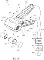
- Still another aspect of the present invention is directed towards ElectroMagnetic Induction (EMI) coil reverse action pliers for use with a power supply for assembling fluid distribution systems.
- the pliers include a lever pair pivoted at a fulcrum to form a long handle pair designed to be comfortably hand gripped by a user and a short jaw pair.
- the jaw pair is normally biased by a biasing member, for example, a spring, and the like, into a closed position to form a coil housing shaped and dimensioned for enveloping an induction weldable pipe connector ready for an induction welding operation.
- the jaw pair can be opened on manually squeezing the handle pair together.
- the pliers can employ EMI coil assemblies of the aforementioned WO 2012/137197 for providing a near uniform electromagnetic field intensity for induction heating an induction weld pipe connector.
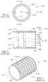
- thermoplastic pipes 10 have an external diameter D1 typically in the range of from 10 mm to 30 mm.
- the thermoplastic pipes 10 have pipe ends 11.
- the pipe ends 11 have peripheral external pipe end surfaces 12 and exposed annular pipe end faces 13.
- the induction weldable pipe connector 100 has a longitudinal pipe connector axis 101 and includes two opposite induction weldable pipe sockets 102A and 102B each intended for forced sliding insertion of a pipe end 11 thereinto.
- the induction weldable pipe connector 100 has a two ply construction including an internal thermoplastic solder lining 103 and a solid ferromagnetic metal susceptor sleeve 104 entirely peripherally enveloping the internal thermoplastic solder lining 103.
- the solder lining 103 has a patterned external solder lining surface 106, an internal solder lining surface 107 and a pair of solder lining end faces 108.
- the solder lining 103 is made of thermoplastic material for welding with thermoplastic pipes 10.
- the solder lining 103 has an internal diameter D2.
- the diameters D1 and D2 are such that a pipe end 11 requires forced sliding inserted into a pipe socket 102 for preloading same. Such preloading ensures that melting of solder lining 103 leads in turn to melting of the peripheral external pipe end surfaces 12 thereby welding them together.
- the susceptor sleeve 104 is preferably formed from steel to ensure uniform heating of its solder lining 103.
- the susceptor sleeve 104 has an external susceptor sleeve surface 109, a patterned internal susceptor sleeve surface 111 and a pair of susceptor sleeve end faces 112.
- the external susceptor sleeve surface 109 is an exposed metal surface which can be printed with technical specification details including inter alia length, internal diameter, external diameter, and the like.
- the patterned external solder lining surface 106 and the patterned internal susceptor sleeve surface 111 are in intimate complementary interlocking contact to facilitate heat transfer from the susceptor sleeve 104 to the solder lining 103.
- Figures 3 and 4 show a series of staggered different diameter adjacent rings 113 along the longitudinal pipe connector axis 101.
- Alternative interlocking patterns include inter alia castellated surfaces, grooved surfaces, and the like.
- the solder lining 103 is formed with a central inwardly directed stop 114 having an internal diameter D3 wherein D1 >D2>D3 such that the pipe ends 11 stop against the inwardly directed stop 114 on their forced sliding insertion into the pipe connector 100.
- the inwardly directed stop 114 includes a first abutment surface 114A facing the induction weldable pipe socket 102A and a second abutment surface 114B facing the induction weldable pipe socket 102B.
- the inwardly directed stop 114 is preferably annular.
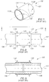
- Electromagnetic induction welding of the induction weldable pipe connector 100 and the two thermoplastic pipes 10 is now described with reference to Figures 5 and 6 :
- the pipe ends 11 are forcibly inserted into the opposite pipe sockets 102 to preload same.
- the annular pipe end faces 13 abut on opposite sides against the central inwardly directed stop 114.
- An electromagnetic induction coil (not shown) is placed over the newly formed assemblage and radio frequency electric current is fed to the electromagnetic induction coil.
- the electromagnetic induction coil generates an electromagnetic field which induces the susceptor sleeve 104 to absorb electromagnetic energy.
- the susceptor sleeve 104 heats up and concurrently heats the solder lining 103.
- the solder lining 103 begins to melt as do the peripheral external pipe end surfaces 12 such that the induction weldable pipe connector 100 and the pipe ends 11 together form a welded sealed joint 120.
- the solder lining 103 also expands as it melts as evidenced by melted thermoplastic material from the solder lining 103 exuding beyond the susceptor sleeve end faces 112 to form annular thermoplastic extrusions 121 on either side of the welded sealed joint 120.
- FIG. 7 shows an induction weldable pipe connector 130 similar to the induction weldable pipe connector 100 and therefore similar parts are likewise numbered.
- the former 130 differs from the latter 100 insofar the former 130 includes a susceptor sleeve 104 having a series 131 of radial small diameter inspection apertures 132 slightly inwards of its left susceptor sleeve end surface 112A and a series 131 of radial small diameter inspection apertures 132 slightly inwards of its right susceptor sleeve end surface 112B.
- Figures 8 and 9 show the welded sealed joint 120 including the annular thermoplastic extrusions 121 and additionally outward radial protrusions 133 formed from the solder lining 103 protruding through the inspection apertures 132.
- Section 2 "Press Fit” Installation Fittings for Assembling Multi-layer Pipe Fluid Distribution Systems
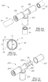
- Figure 10 shows a T-shaped "press fit" installation fitting 200 for connecting three same diameter multi-layer pipes 20.
- FIG 11 shows multi-layer pipe 20 has a triple layer construction including an external plastic layer 21, an aluminum core layer 22, and an internal plastic layer 23.
- the multi-layer pipe 20 has an external pipe diameter D1 the same as the plastic pipe 10 and an internal pipe diameter D4.
- the multi-layer pipe 20 includes a pipe end 24 and an exposed annular pipe end face 26 with an annular aluminum core end face 27 which is prone to oxidation.
- FIGs 10 and 12 show the T-shaped "press fit" installation fitting 200 includes a T-shaped housing 201 having three pipe sockets 202 for each sealingly receiving a pipe end 24 on forced sliding insertion thereinto.
- Each pipe socket 202 includes an annular abutment element 203 mounted on a pipe tang 204 with two or more O-rings 206.
- the pipe tang 204 has an external diameter D5.
- the pipe sockets 202 and the pipe tangs 204 are dimensioned such that a multi-layer pipe 20 requires forced sliding insertion into a pipe socket 202 for ensuring the O rings 206 seal against the internal plastic layer 23.
- the pipe ends 24 are inserted into the pipe sockets 202 until abutment against the abutment element 203.
- Each press fit socket 202 includes a sleeve 207 intended to be pressed onto a pipe end 24 in a pressing operation for securing purposes.
- Section 3 Plastic Installation Fittings for Induction Welding Multi-layer Pipe Fluid Distribution Systems
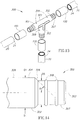
- FIGS 13 and 14 show a T-shaped installation fitting 300 for connecting the three same diameter multi-layer pipes 20 as the T-shaped "press fit” installation fitting 200.
- the T-shaped installation fitting 300 requires the use of discrete induction weldable pipe connectors for assembly purposes in contradistinction to the T-shaped "press fit” installation fitting 200 which includes the integral sleeves 207 for securing purposes.
- the multi-layer pipes 20 are equivalent to the plastic pipes 10 in terms of induction welding insofar as they include the external plastic layer 21.
- the T-shaped installation fitting 300 can be made entirely from thermoplastic material or thermosetting plastic material except for conventional O rings used for sealing against the internal plastic layer 23.
- the T-shaped installation fitting 300 can be assembled with the WO 2012/137197 induction weldable pipe connectors. Alternatively, the T-shaped installation fitting 300 can be assembled with induction weldable pipe connectors 140 described hereinbelow.
- the T-shaped installation fitting 300 includes a housing 301 having three tubular plastic pipe ends 302. Each pipe end 302 has a pipe end centerline 303 and an exposed external peripheral plastic surface 304 co-directional with the pipe end centerline 303. The pipe end 302 has a shoulder 306 converging to a tubular pipe tang 307. The pipe tang 307 is provided with at least two O rings 308 similar to the pipe tang 204. The pipe end 302 preferably tapers to the pipe tang 307 such that the shoulder 306 subtends an included acute angle ⁇ with the pipe end centerline 303 in Figure 14 's front elevation view. The included acute angle ⁇ is preferably within the range of 45° ⁇ 10°.
- the shoulder 306 can form a right angle with the pipe tang 307 such that the exposed external peripheral plastic surface 304 has a stepped configuration.
- the pipe end 302 includes a full insertion indicator 309 for providing a visual user indication that a pipe end 302 has been fully inserted into an injection weldable pipe connector when the full insertion indicator 309 is adjacent thereto.
- the pipe end 302 is shaped and dimensioned for forced sliding insertion into an induction weldable pipe socket 102 similar to a pipe end 24.
- the pipe tang 307 is shaped and dimensioned for forced sliding insertion into a multi-layer pipe 20 such that its O rings 308 sealing contact with the internal plastic surface 23. Accordingly, the pipe end 302 has an external pipe diameter D1 similar to the multi-layer pipe 20 and the pipe tang 307 has an external diameter D5 similar to the pipe tang 204.
- Section 4 Induction Weldable Pipe Connector having Major Central Pipe Connector Section and Reduced Thickness Minor Lateral Pipe Connector Section Pair
- Figures 15 and 16 show an induction weldable pipe connector 140 differs from the WO 2012/137197 induction weldable pipe connectors insofar as they include a major central pipe connector section 141 and a minor lateral pipe connector section pair 142 respectively at the induction weldable pipe socket pair 102.
- the induction weldable pipe connector 140 has a length L1
- the major central pipe connector section 141 has a length L2
- the major central pipe connector section 141 has a thickness T1 and the each minor lateral pipe connector section 142 has a thickness T2 wherein T2 ⁇ T1.
- Each minor lateral pipe connector section 142 is of reduced thickness compared to the major central connector section 141 such that they absorb less induction energy than the major central pipe connector section 141 per unit length, thereby ensuring the major central pipe connector section 141 is induction heated to a higher temperature than the minor lateral pipe connector section pair 142.
- T2 ⁇ 1 ⁇ 2 T1.
- the minor lateral pipe connector section pair 142 is preferably formed with the radial small diameter apertures 132.
- Figure 17 shows a pre-welded joint 145 of the pipe end 302, the induction weldable pipe connector 140, and the multi-layer pipe 20.
- the pipe end 302 is inserted into the induction weldable pipe socket 102A until abutment of the shoulder 306 against the first annular abutment surface 114A.
- the multi-layer pipe 20 is inserted into the induction weldable pipe socket 102B until abutment against the second annular abutment surface 114B. Sliding insertion of the pipe end 302 and the multi-layer pipe 20 into the induction weldable pipe connector 140 sealingly slides the pipe tang 307 into the multi-layer pipe 20 by virtue of the O rings 308 sealingly engaging the internal plastic layer 23.
- the pre-welded joint 145 includes a circular cavity 146 bound by the shoulder 306, the internal thermoplastic solder lining 103 and the exposed annular pipe end surface 26.
- FIG 18 shows a welded sealed joint 147 subsequent to application of induction energy to the pre-welded joint 145 in a similar manner as explained in aforesaid WO 2012/137197 .
- the internal thermoplastic solder lining 103 melts to form the annular plastic extrusions forms 121 and the outward radial protrusions 133 as described hereinabove with reference to WO 2012/137197 Figures 7 to 9 .
- the internal thermoplastic solder lining 103 also melts and flows radially inwards towards the pipe tang 307 to fill the circular cavity 146 for sealing the annular aluminum core end surface 27. Such sealing provides additional protection against oxidation of the aluminum core layer 22.
- Section 6 Induction Weldable Pipe Connectors with Integral Solder Flow Barrier For End to End Induction Welding Plastic Pipes with Inherent Mechanical Rigidity
- FIGS 19 to 21 show an induction weldable pipe connector with integral solder flow barrier 150 (hereinafter referred to as "assisted induction weldable pipe connector”) for end to end induction welding of two plastic pipes with inherent mechanical rigidity.
- plastic pipes include multi-layer pipes 20 with an aluminium core layer, thermosetting plastic pipes, and the like.
- the assisted induction weldable pipe connector 150 is modified from the induction weldable pipe connector 140.
- an assisted induction weldable pipe connector can be modified from WO 2012/137197 induction weldable pipe connectors 100 and 130.
- the assisted induction weldable pipe connector 150 includes an induction weldable pipe connector 151, a solder flow barrier 152 and a mounting arrangement 153 for mounting the solder flow barrier 152 inside the induction weldable pipe connector 151.
- the solder flow barrier 152 includes a central flange 154 employed by the mounting arrangement 153.
- Suitable mounting arrangements 153 include inter alia a mechanical arrangement, gluing, and the like.
- the solder flow barrier 152 is preferably formed from a dissolvable material for initially assisting an induction welding operation of two multi-layer pipes 20 before being dissolved pursuant to fluid flowing therethrough.
- the assisted induction weldable pipe connector 150 has the same length L1 as the induction weldable pipe connector 140 and the solder flow barrier 152 has a length L4 wherein L4 ⁇ L1. Typically L4 ⁇ 1 ⁇ 2 L1.
- the solder flow barrier 152 includes a pipe tang pair 156 corresponding with the induction weldable pipe socket pair 102.
- the pipe tang pair 156 has an external diameter D5 similar to the pipe tangs 204 and 307 for the same purpose of sealing against the internal plastic layer 23.
- the solder flow barrier 152 preferably includes a throughgoing bore 157 co-directional with the longitudinal pipe connector axis 101.
- Figure 22A to Figure 22C show the use of the assisted induction weldable pipe connector 150 for end to end induction welding two multi-layer pipes 20.
- Figure 22A shows a pre-welded joint 160 of the assisted induction weldable pipe connector 150 and the multi-layer pipes 20 on forced sliding insertion of the multi-layer pipes 20 into opposite induction weldable pipe sockets 102 until abutment of their respective exposed annular pipe end faces 26 against the central inwardly directed stop 114.
- the pipe tang pair 156 is slidingly inserted into the pipe ends 24.
- the annular pipe end faces 26 and the assisted induction weldable pipe connector 150 form annular contact zones 161A and 161B externally bound by the internal thermoplastic solder lining 103 and internally bound by the solder flow barrier 152.
- the annular contact zones 161A and 161B contain minute cavities due to surface contact tolerances between the exposed annular pipe end faces 26 and the abutment surfaces 114A and 114B.
- FIG 22B shows a welded sealed joint 162 subsequent to application of induction energy to the pre-welded joint 160 in a similar manner as explained in aforesaid WO 2012/137197 .
- the internal thermoplastic soldering lining 103 melts and expands to flow radially inwards towards the solder flow barrier 152 and also peripherally along the pipe end 302 and the multi-layer pipe 20 to form annular thermoplastic extrusions 121.
- Such inward expansion fills the annular contact zones 161 thereby hermetically sealing the opposite annular aluminum core end surfaces 27 instead of O ring protection to prevent their oxidation.
- Figure 22C shows the welded sealed joint 162 after the solder flow barrier 152 has been dissolved by fluid F flowing through the multi-layer pipes 20.
- Section 7 Induction Weldable Pipe Connectors with Integral Solder Flow Barrier For End to End Induction Welding Thermoplastic Pipes
- FIGS 23 and 24 show an induction weldable pipe connector with integral solder flow barrier 170 (hereinafter referred to as "assisted induction weldable pipe connector") for end to end induction welding of two same diameter thermoplastic pipes 10.
- the assisted induction weldable pipe connector 170 has the same construction and use as the assisted induction weldable pipe connector 150.
- the assisted induction weldable pipe connector 170 includes an induction weldable pipe connector 171, a solder flow barrier 172 and a mounting arrangement 173 for mounting the solder flow barrier 172 inside the induction weldable pipe connector 171.
- the solder flow barrier 172 includes a central flange 174 employed by the mounting arrangement 173 and a pipe tang pair 176 corresponding with the induction weldable pipe socket pair 102.
- the pipe tang pair 176 has an external diameter D6 for forced sliding insertion into the thermoplastic pipes 10.
- the solder flow barrier 172 preferably includes a throughgoing bore 177 co-directional with the longitudinal pipe connector axis 101.
- the assisted induction weldable pipe connector 170 has the same length L1 as the induction weldable pipe connector 140 and the solder flow barrier 172 has a length L4 wherein L4>L1.
- the solder flow barrier 172 is longer than the induction weldable pipe connector 171 since in addition to controlling the radial inward directed flow of melted solder lining from the internal thermoplastic solder lining 103 towards the solder flow barrier 172 similar to the solder flow barrier 152, the solder flow barrier 172 provides mechanical support for the two thermoplastic pipes 10 which is not required in the case of plastic pipes having inherent mechanical rigidity.
- the solder flow barrier 172 necessarily has to extend to unheated lengths of the pipe ends 11. Typically L4 ⁇ 1.5 L1.
- FIG 25 shows an induction weldable pipe connector with integral solder flow barrier 180 (hereinafter referred to as "assisted induction weldable pipe connector") for use during end to end induction welding of two same diameter thermoplastic pipes 10.
- the assisted induction weldable pipe connector 180 has a similar construction and use as the assisted induction weldable pipe connector 170.
- the latter 180 differs from the former 170 insofar as the latter 180 includes a solder flow barrier 181 formed from a thermosetting plastic material instead of dissolvable material.
- the solder flow barrier 181 has a pipe tang pair 182 corresponding with the induction weldable pipe socket pair 102.
- the thermosetting plastic material has a melting temperature considerably higher than the melting temperature of the internal thermoplastic solder lining 103 such that it does not melt during an induction welding operation.
- the solder flow barrier 181 is a permanent component in the assisted induction weldable pipe connector 180 and therefore is preferably made as thin as possible on the one hand to provide the required mechanical support during an induction welding operation and on the other hand to minimize narrowing the internal diameter of the assisted induction weldable pipe connector 180.
- the solder slow barrier 181 has a longitudinal throughgoing bore 183 co-directional with longitudinal pipe connector axis 101.
- FIG. 26A to Figure 26C show the use of the assisted induction weldable pipe connector 170 for end to end induction welding of two same diameter thermoplastic pipes 10.
- FIG 26A shows a pre-welded joint 190 of the assisted induction weldable pipe connector 170 and the thermoplastic pipes 10 on forced sliding insertion of the thermoplastic pipes 10 into opposite induction weldable pipe sockets 102 until abutment of their respective exposed annular end faces 13 against the central inwardly directed stop 114.
- the pipe tang pair 176 is slidingly inserted into the pipe ends 11.
- the exposed annular pipe end faces 13 and the assisted induction weldable pipe connector 170 form annular contact zones 191A and 191B externally bound by the internal thermoplastic solder lining 103 and internally bound by the solder flow barrier 172.
- the annular contact zones 191A and 191B contain minute cavities due to surface contact tolerances between the exposed annular pipe end faces 13 and the abutment surfaces 114A and 114B.
- Figure 26B shows a welded sealed joint 192 subsequent to application of induction energy to the pre-welded joint 190 in a similar manner as explained in aforesaid WO 2012/137197 .
- the internal thermoplastic soldering lining 103 melts and flows inwards towards the solder flow barrier 172 as it expands to fill the annular contact zones 191.
- the pipe tang pair 176 prevents any plastic deformation of the pipe ends 11.
- Figure 26C shows the welded sealed joint 192 after the solder flow barrier 172 has been dissolved by on fluid F flowing through the multi-layer pipes 10.
- FIGA and Figure 27B show the use of the assisted induction weldable pipe connector 180 for end to end induction welding of two same diameter thermoplastic pipes 10.
- FIG 27A shows a pre-welded joint 195 of the assisted induction weldable pipe connector 180 and the thermoplastic pipes 10 on forced sliding insertion of the thermoplastic pipes 10 into opposite induction weldable pipe sockets 102 until abutment of their respective exposed annular end faces 13 against the central inwardly directed stop 114.
- the pipe tang pair 182 is slidingly inserted into the pipe ends 11.
- the exposed annular pipe end faces 13 and the assisted induction weldable pipe connector 180 form annular contact zones 196A and 196B externally bound by the internal thermoplastic solder lining 103 and internally bound by the solder flow barrier 181.
- the annular contact zones 196A and 196B contain minute cavities due to surface contact tolerances between the exposed annular pipe end faces 13 and the abutment surfaces 114A and 114B.
- FIG. 27B shows a welded sealed joint 197 subsequent to application of induction energy to the pre-welded joint 195 in a similar manner as explained in aforesaid WO 2012/137197 .
- the internal thermoplastic soldering lining 103 melts and flows inwards towards the solder flow barrier 181 as it expands to fill the annular contact zones 196.
- the pipe tang pair 182 prevents any plastic deformation of the pipe ends 11.
- FIGS 28 to 30 show ElectroMagnetic Induction (EMI) coil reverse action pliers 400 for use with a power supply 450 for induction welding of induction weldable pipe connectors to assemble fluid distribution systems.
- the pliers 400 can be designed for use with WO2012/13797 induction weldable pipe connectors and induction weldable pipe connectors 140.
- the power supply 450 includes a user interface 451 for controlling induction welding operations.
- the user interface 451 includes a START switch 452 for activating an induction welding operation.
- the user interface 451 includes other controls for inputting pipe material and pipe diameter.
- Pipe material controls include inter alia touch selection buttons for PP-R, PEX, HDPE, ML and the like.
- Pipe diameter controls include inter alia touch selection buttons for 16-24 mm diameter, 25-32 mm diameter, 33-50 mm diameter, and 110 mm diameter.
- the power supply 450 determines the durations of induction welding operations and the voltage of induction welding operations based on the user input.
- the pliers 400 include an elongated lever pair 401 pivoted at a fulcrum 402 for forming a long handle pair 403 for being comfortably hand gripped by a user to hold and use the pliers 400 and a short jaw pair 404.
- the pliers 400 include a biasing member 406 for normally biasing the jaw pair 404 into a closed position for defining a tubular coil housing 407 having a longitudinal coil housing axis 408 transverse to the lever pair 401.
- the jaw pair 404 can be opened on manually squeezing the handle pair 403 together to overcome the biasing member 406.
- the coil housing 407 is shaped and dimensioned to envelope an induction weldable pipe connector 140 therein on co-alignment of the longitudinal coil housing axis 408 and the longitudinal pipe connector axis 101.
- the jaw pair 404 includes an electromagnetic induction coil assembly 409 for applying induction energy to the induction weldable pipe connector 140.
- the pliers 400 include an electrical wire pair 411 for connection to the power supply 450.
- the electrical wire pair 411 is separated such that one electrical wire 411A extends along one handle 403A and the other electrical wire 411B extends along the other handle 403B to reduce energy loss between the electrical wire pair 411.
- the jaw pair 404 has stepped internal surfaces 412 which are shaped and dimensioned to snugly receive an induction weldable pipe connector 140.
- the stepped internal surfaces 412 are formed with a central section 412A and an opposite end section pair 412B for correspondingly contacting the major central pipe connector section 141 and the minor lateral pipe connector sections 142.
- the opposite end section pair 412B is preferably each formed with a ribbed surface 413.
- the jaw pair 404 ensures induction weldable pipe connectors 140 are optimally placed therein for optimal transfer of induction energy from the pliers 400.
- the pliers 400 can include an ongoing induction welding operation indicator 414 for providing a user indication that an induction welding operation is in process.
- the user indication can be in the form of a visual alert, a vibrating alert, and the like.
- the pliers 400 can include a user operated switch 416 for operating the power supply 450 for starting and stopping an induction welding operation instead of from the power supply's START switch 452.
- the pliers 400 can additionally include a built-in lock mechanism 417 for preventing squeezing the handle pair 403 together during an induction welding operation.
- the lock mechanism 417 includes a pivotal rigid lock member 418 which is activated into an operative state during an induction welding operation (see Figure 29 ).
- An induction weldable pipe connector for end to end induction welding a pipe pair each having a pipe end, the induction weldable pipe connector comprising:
- solder flow barrier includes a central flange for mounting on said induction weldable pipe connector.
- solder flow barrier is made from dissolvable material for being dissolved on fluid flow through the pipe pair.
- solder flow barrier is tubular having a longitudinal throughgoing bore co-directional with the longitudinal pipe connector axis.
- solder flow barrier is tubular having a longitudinal throughgoing bore co-directional with the longitudinal pipe connector axis and made from a thermoset plastic material having a melting temperature higher than the melting temperature of said internal thermoplastic solder lining.
- a fluid distribution system including at least one induction weldable pipe connector according to one of examples 4 to 10.
- solder flow barrier includes a central flange for mounting on the induction weldable pipe connector.
- solder flow barrier is made from dissolvable material for being dissolved on fluid flow through the pipe pair.
- solder flow barrier is tubular having a longitudinal throughgoing bore co-directional with the longitudinal pipe connector axis.
- solder flow barrier is tubular having a longitudinal throughgoing bore co-directional with the longitudinal pipe connector axis and made from a thermoset plastic material having a melting temperature higher than the melting temperature of the internal thermoplastic solder lining.
- Electromagnetic induction coil reverse action pliers for use with a power supply having a first polarity terminal and a second opposite polarity terminal for induction welding an induction weldable pipe connector and a plastic pipe end to form a welded sealed joint, the pliers comprising:
- said induction coil includes an electrical wire pair for connection to the power supply wherein said electrical wire pair includes a first electrical wire extending along a first handle of said handle pair and a second electrical wire extending along a second handle of said handle pair.
- said coil housing has a stepped internal surface including a central section and a pair of lateral ends wherein said lateral ends have a smaller internal diameter than said central section.
Landscapes
- Engineering & Computer Science (AREA)
- Mechanical Engineering (AREA)
- General Engineering & Computer Science (AREA)
- Physics & Mathematics (AREA)
- Health & Medical Sciences (AREA)
- Electromagnetism (AREA)
- Toxicology (AREA)
- Thermal Sciences (AREA)
- Lining Or Joining Of Plastics Or The Like (AREA)
- Branch Pipes, Bends, And The Like (AREA)
- Standing Axle, Rod, Or Tube Structures Coupled By Welding, Adhesion, Or Deposition (AREA)
- Non-Disconnectible Joints And Screw-Threaded Joints (AREA)
Abstract
Description
- The invention relates to electromagnetic induction welding of fluid distribution systems for the transport of fluids in residential, commercial and industrial plumbing systems.
- Commonly owned WIPO International Publication No.
WO 2012/137197 entitled Electromagnetic Induction Welding of Plastic Pipe Distribution Systems discloses induction weldable pipe connectors and electromagnetic induction coil assemblies for use in clamping the induction weldable pipe connector on plastic pipes. The plastic pipes can be made from thermoplastics including inter alia PVC, PP, PP-R, HDPE and the like, and thermosetting plastics including inter alia PEX, and the like. The plastic pipes can have can be fabricated from a single plastic material throughout or alternatively have a multi-layer composition. - The induction weldable pipe connectors each have at least one induction weldable pipe socket. Each induction weldable pipe socket includes a solid metal susceptor sleeve enveloping an internal thermoplastic solder lining. The induction weldable pipe connectors can be implemented in a wide range of pipe fittings including inter alia couplers, elbow fittings, T fittings, Y fittings, X fittings, and the like. The induction weldable pipe connectors can be designed for end-to-end electromagnetic induction welding of two different diameter plastic pipes. The induction weldable pipe connectors can include a connector end with an external or internal screw thread.
- Induction welding of an induction weldable pipe connector and a thermoplastic pipe can transfer inadvertently excessive heat energy to a pipe end thereby introducing an undesirable measure of uncertainty in an induction welding operation. Such inadvertent excessive heat energy can be due to a wide range of factors including inter alia tolerances of a thermoplastic pipe and an induction weldable pipe connector, the surface contact between a pipe end and an induction weldable pipe socket, the duration of an induction welding operation, and the like. Such inadvertent excessive heat energy can lead to undesirable internal plastic deformations of a pipe end which may be undetectable to construction personnel assembling a fluid distribution system. Such internal plastic deformations can cause disruptions in fluid flow through a fluid distribution system at an induction weldable pipe connector.
- There is a need for controlling induction welding operations to ensure uniformly welded sealed joints to a high degree of certainty.
- The European market employs fluid distribution systems made of multi-layer pipes including an aluminum core layer sandwiched between one or more plastic layers including inter alia PEX, and the like. The aluminum core layers afford inherent mechanical rigidity compared to a thermoplastic pipe and prevent diffusion of oxygen or other gases diffusing into a fluid flow. Fluid distribution systems assembled from multi-layer pipes employ inter alia "press fit" fitting systems. The "press fit" fitting systems include "press fit" installation fittings having two or more "press fit" pipe sockets for sealing and securing a pipe end. The "press fit" installation fittings are typically made from metallic or plastic materials. The "press fit" pipe sockets include an annular abutment element mounted on a tubular pipe tang with two or more O-rings for forced sliding insertion into a pipe end. The "press fit" sockets include an elongated sleeve intended to be pressed onto a pipe end in a pressing operation for securing purposes. "Press fit" installation fittings are available in a wide range including inter alia couplers, elbow fittings, T fittings, Y fittings, X fittings, and the like.
- "Press fit" installation fittings are relatively expensive and construction personnel require a considerable range of "press fit" installation fittings to complete a multi-layer pipe fluid distribution system. Moreover, pipe tangs necessarily have a smaller internal diameter than the internal diameter of a multi-layer pipe into which they are inserted thereby affecting fluid flow through a "press fit" installation fitting.
- There is a need for alternative approaches for assembling multi-layer pipe fluid distribution systems.
- One aspect of the present invention is directed toward installation fittings for use with
WO 2012/137197 induction weldable pipe connectors for assembling multi-layer pipe fluid distribution systems. The installation fittings of the present invention are similar to the aforesaid "press fit" installation fittings insofar as they include one or more tubular pipe tangs with at least two O rings for forced sliding insertion into a multi-layer pipe for sealingly engaging an internal plastic layer for protecting its annular aluminium core end surface. The installation fittings of the present invention differ from "press fit" installation fittings insofar as they are not integrally formed with a securing arrangement. Rather they are employed with discreteWO 2012/137197 induction weldable pipe connector for in situ assembly. The installation fittings of the present invention can be supplied in a wide range similar to "press fit" installation fittings, namely, couplers, elbow fittings, T fittings, Y fittings, X fittings, and the like. - Another aspect of the present invention is directed towards induction weldable pipe connectors of the present invention having a minor lateral pipe connector section pair of reduced thickness compared to a major central pipe connector section such that the former absorb less induction energy than the latter per unit length, thereby ensuring the major central pipe connector section is induction heated to a higher temperature than the minor lateral pipe connector section pair.
- Yet another aspect of the present invention is directed towards induction weldable pipe connectors with integral solder flow barrier for use in assembling fluid distribution systems. The integral solder flow barriers are mounted inside induction weldable pipe connectors and designed to control the inward radial flow of melted internal thermoplastic solder lining on application of induction energy thereby affording a more precise induction welding operation. Induction weldable pipe connectors with integral solder flow barriers according to the present invention can be tailored for assembling either thermoplastic pipes or plastic pipes having inherent mechanical rigidity either by virtue of being made of thermoset plastic materials or having an aluminium core layer.
- In the former case of thermoplastic pipes, an integral solder flow barrier is additionally intended to provide structural rigidity to pipe ends undergoing induction welding and therefore it is necessarily longer than its associated induction weldable pipe connector to extend to unheated lengths of the pipe ends being induction welded together. Integral solder flow barriers for use with thermoplastic pipes can be made of a thermoset plastic material having a higher melting temperature than an internal thermoplastic solder lining such that it is not affected during an induction welding operation. Alternatively, integral solder flow barriers can be made from a dissolvable material intended to be dissolved by a fluid flowing through a fluid distribution system. Suitable dissolvable materials include common salt.
- In the latter case of plastic pipes having inherent mechanical rigidity, an integral solder flow barrier can be considerably shorter than its associated induction weldable pipe connector, thereby saving dissolvable material in the case of a dissolvable integral solder flow barrier. Flow control over melting internal thermoplastic solder lining is particularly important in the case of multi-layer pipes with aluminium core layers to ensure that the melting internal thermoplastic solder lining material absolutely seals the annular aluminium core end faces to preclude their oxidation which can lead to pipe failure.
- Still another aspect of the present invention is directed towards ElectroMagnetic Induction (EMI) coil reverse action pliers for use with a power supply for assembling fluid distribution systems. The pliers include a lever pair pivoted at a fulcrum to form a long handle pair designed to be comfortably hand gripped by a user and a short jaw pair. The jaw pair is normally biased by a biasing member, for example, a spring, and the like, into a closed position to form a coil housing shaped and dimensioned for enveloping an induction weldable pipe connector ready for an induction welding operation. The jaw pair can be opened on manually squeezing the handle pair together. The pliers can employ EMI coil assemblies of the aforementioned
WO 2012/137197 for providing a near uniform electromagnetic field intensity for induction heating an induction weld pipe connector. - In order to understand the invention and to see how it can be carried out in practice, preferred embodiments will now be described, by way of non-limiting examples only, with reference to the accompanying drawings in which similar parts are likewise numbered, and in which:
-
Fig. 1 corresponds to aforesaidWO 2012/137197 Figure 1 ; -
Fig. 2 corresponds to aforesaidWO 2012/137197 Figure 2 ; -
Fig. 3 corresponds to aforesaidWO 2012/137197 Figure 3 ; -
Fig. 4 corresponds to aforesaidWO 2012/137197 Figure 4 ; -
Fig. 5 corresponds to aforesaidWO 2012/137197 Figure 5 ; -
Fig. 6 corresponds to aforesaidWO 2012/137197 Figure 6 and is a longitudinal cross section along line B-B inFigure 5 ; -
Fig. 7 corresponds to aforesaidWO 2012/137197 Figure 7 ; -
Fig. 8 corresponds to aforesaidWO 2012/137197 Figure 8 ; -
Fig. 9 corresponds to aforesaidWO 2012/137197 Figure 9 and is a longitudinal cross section along line C-C inFigure 8 ; -
Fig. 10 is a perspective view of a conventional T-shaped "press fit" installation fitting for connecting three same diameter multi-layer pipes; -
Fig. 11 is an end elevation view of a multi-layer pipe; -
Fig. 12 is a partially exploded view of the T-shaped "press fit" installation fitting; -
Fig. 13 is a perspective view of a T-shaped installation fitting in accordance with the teachings of the present invention for use with three induction weldable pipe connectors for connecting three same diameter multi-layer pipes; -
Fig. 14 is a front elevation view of a pipe end of theFigure 13 T-shaped installation fitting; -
Fig. 15 is a perspective view of a pre-assembled assemblage of theFigure 14 pipe end, an induction weldable pipe connector, and a multi-layer pipe; -
Fig. 16 is a longitudinal cross section of theFigure 15 induction weldable pipe connector along line 16-16 inFigure 15 ; -
Fig. 17 is a close-up longitudinal cross section of a pre-welded joint of the assembledFigure 15 assemblage of the pipe end, the induction weldable pipe connector, and the multi-layer pipe; -
Fig. 18 is a close-up longitudinal cross section of a welded sealed joint of the assembledFigure 15 assemblage of the pipe end, the induction weldable pipe connector, and the multi-layer pipe; -
Fig. 19 is a perspective view of an induction weldable pipe connector with integral solder flow barrier for use during end to end induction welding of two same diameter plastic pipes with inherent mechanical rigidity; -
Fig. 20 is an exploded view of theFigure 19 induction weldable pipe connector; -
Fig. 21 is a longitudinal cross section of theFigure 19 induction weldable pipe connector along line 21-21 inFigure 19 ; -
Figs. 22A to 22C show the use of theFigure 19 induction weldable pipe connector for end to end induction welding of two same diameter multi-layer pipes; -
Fig. 23 is a perspective view of an induction weldable pipe connector with integral solder flow barrier made from dissolvable material for use during end to end induction welding of two same diameter thermoplastic pipes; -
Fig. 24 is a longitudinal cross section of theFigure 23 induction weldable pipe connector with integral solder flow barrier along line 24-24 inFigure 23 ; -
Fig. 25 is a perspective view of an induction weldable pipe connector with integral solder flow barrier made from thermoset plastic material for use during end to end induction welding of two same diameter thermoplastic pipes; -
Figs. 26A to 26C show the use of theFigure 23 induction weldable pipe connector for end to end welding of two same diameter thermoplastic pipes; -
Figs. 27A and 27B show the use of theFigure 25 induction weldable pipe connector for end to end welding of two same diameter thermoplastic pipes; -
Fig. 28 is a perspective view of electromagnetic induction coil reverse action pliers for use with a power supply, an induction weldable pipe connector, and a pair of multi-layer pipes; -
Fig. 29 is a perspective view of the pliers with a built-in lock mechanism in an operative state for preventing opening the jaw pair during an induction welding operation; and -
Fig. 30 is a longitudinal cross section of the pliers during an induction welding operation for end-to-end connecting the multi-layer pipe pair along line 30-30 inFigure 29 . - Commonly owned
WO 2012/137197 Figures 1 to 4 show an inductionweldable pipe connector 100 for electromagnetic induction welding to a pair of same diameter thermoplastic pipes 10. The thermoplastic pipes 10 have an external diameter D1 typically in the range of from 10 mm to 30 mm. The thermoplastic pipes 10 have pipe ends 11. The pipe ends 11 have peripheral external pipe end surfaces 12 and exposed annular pipe end faces 13. - The induction
weldable pipe connector 100 has a longitudinalpipe connector axis 101 and includes two opposite inductionweldable pipe sockets pipe end 11 thereinto. The inductionweldable pipe connector 100 has a two ply construction including an internal thermoplastic solder lining 103 and a solid ferromagneticmetal susceptor sleeve 104 entirely peripherally enveloping the internalthermoplastic solder lining 103. - The
solder lining 103 has a patterned externalsolder lining surface 106, an internalsolder lining surface 107 and a pair of solder lining end faces 108. Thesolder lining 103 is made of thermoplastic material for welding with thermoplastic pipes 10. Thesolder lining 103 has an internal diameter D2. The diameters D1 and D2 are such that apipe end 11 requires forced sliding inserted into a pipe socket 102 for preloading same. Such preloading ensures that melting of solder lining 103 leads in turn to melting of the peripheral external pipe end surfaces 12 thereby welding them together. - The
susceptor sleeve 104 is preferably formed from steel to ensure uniform heating of itssolder lining 103. Thesusceptor sleeve 104 has an externalsusceptor sleeve surface 109, a patterned internalsusceptor sleeve surface 111 and a pair of susceptor sleeve end faces 112. The externalsusceptor sleeve surface 109 is an exposed metal surface which can be printed with technical specification details including inter alia length, internal diameter, external diameter, and the like. - The patterned external
solder lining surface 106 and the patterned internalsusceptor sleeve surface 111 are in intimate complementary interlocking contact to facilitate heat transfer from thesusceptor sleeve 104 to thesolder lining 103.Figures 3 and 4 show a series of staggered different diameteradjacent rings 113 along the longitudinalpipe connector axis 101. Alternative interlocking patterns include inter alia castellated surfaces, grooved surfaces, and the like. - The
solder lining 103 is formed with a central inwardly directedstop 114 having an internal diameter D3 wherein D1 >D2>D3 such that the pipe ends 11 stop against the inwardly directedstop 114 on their forced sliding insertion into thepipe connector 100. The inwardly directedstop 114 includes afirst abutment surface 114A facing the inductionweldable pipe socket 102A and asecond abutment surface 114B facing the inductionweldable pipe socket 102B. The inwardly directedstop 114 is preferably annular. - Electromagnetic induction welding of the induction
weldable pipe connector 100 and the two thermoplastic pipes 10 is now described with reference toFigures 5 and 6 : The pipe ends 11 are forcibly inserted into the opposite pipe sockets 102 to preload same. The annular pipe end faces 13 abut on opposite sides against the central inwardly directedstop 114. - An electromagnetic induction coil (not shown) is placed over the newly formed assemblage and radio frequency electric current is fed to the electromagnetic induction coil. The electromagnetic induction coil generates an electromagnetic field which induces the
susceptor sleeve 104 to absorb electromagnetic energy. Thesusceptor sleeve 104 heats up and concurrently heats thesolder lining 103. Thesolder lining 103 begins to melt as do the peripheral external pipe end surfaces 12 such that the inductionweldable pipe connector 100 and the pipe ends 11 together form a welded sealed joint 120. Thesolder lining 103 also expands as it melts as evidenced by melted thermoplastic material from the solder lining 103 exuding beyond the susceptor sleeve end faces 112 to form annularthermoplastic extrusions 121 on either side of the welded sealed joint 120. - Commonly owned
WO 2012/137197 Figure 7 shows an inductionweldable pipe connector 130 similar to the inductionweldable pipe connector 100 and therefore similar parts are likewise numbered. The former 130 differs from the latter 100 insofar the former 130 includes asusceptor sleeve 104 having aseries 131 of radial smalldiameter inspection apertures 132 slightly inwards of its left susceptorsleeve end surface 112A and aseries 131 of radial smalldiameter inspection apertures 132 slightly inwards of its right susceptorsleeve end surface 112B.Figures 8 and 9 show the welded sealed joint 120 including the annularthermoplastic extrusions 121 and additionally outwardradial protrusions 133 formed from the solder lining 103 protruding through theinspection apertures 132. -
Figure 10 shows a T-shaped "press fit" installation fitting 200 for connecting three same diametermulti-layer pipes 20. -
Figure 11 showsmulti-layer pipe 20 has a triple layer construction including anexternal plastic layer 21, analuminum core layer 22, and aninternal plastic layer 23. Themulti-layer pipe 20 has an external pipe diameter D1 the same as the plastic pipe 10 and an internal pipe diameter D4. Themulti-layer pipe 20 includes apipe end 24 and an exposed annular pipe end face 26 with an annular aluminumcore end face 27 which is prone to oxidation. -
Figures 10 and 12 show the T-shaped "press fit" installation fitting 200 includes a T-shapedhousing 201 having threepipe sockets 202 for each sealingly receiving apipe end 24 on forced sliding insertion thereinto. Eachpipe socket 202 includes anannular abutment element 203 mounted on apipe tang 204 with two or more O-rings 206. Thepipe tang 204 has an external diameter D5. Thepipe sockets 202 and the pipe tangs 204 are dimensioned such that amulti-layer pipe 20 requires forced sliding insertion into apipe socket 202 for ensuring the O rings 206 seal against theinternal plastic layer 23. The pipe ends 24 are inserted into thepipe sockets 202 until abutment against theabutment element 203. Eachpress fit socket 202 includes asleeve 207 intended to be pressed onto apipe end 24 in a pressing operation for securing purposes. -
Figures 13 and 14 show a T-shaped installation fitting 300 for connecting the three same diametermulti-layer pipes 20 as the T-shaped "press fit"installation fitting 200. The T-shaped installation fitting 300 requires the use of discrete induction weldable pipe connectors for assembly purposes in contradistinction to the T-shaped "press fit" installation fitting 200 which includes theintegral sleeves 207 for securing purposes. Themulti-layer pipes 20 are equivalent to the plastic pipes 10 in terms of induction welding insofar as they include theexternal plastic layer 21. The T-shaped installation fitting 300 can be made entirely from thermoplastic material or thermosetting plastic material except for conventional O rings used for sealing against theinternal plastic layer 23. The T-shaped installation fitting 300 can be assembled with theWO 2012/137197 induction weldable pipe connectors. Alternatively, the T-shaped installation fitting 300 can be assembled with inductionweldable pipe connectors 140 described hereinbelow. - The T-shaped installation fitting 300 includes a
housing 301 having three tubular plastic pipe ends 302. Eachpipe end 302 has apipe end centerline 303 and an exposed external peripheralplastic surface 304 co-directional with thepipe end centerline 303. Thepipe end 302 has ashoulder 306 converging to atubular pipe tang 307. Thepipe tang 307 is provided with at least two Orings 308 similar to thepipe tang 204. Thepipe end 302 preferably tapers to thepipe tang 307 such that theshoulder 306 subtends an included acute angle α with thepipe end centerline 303 inFigure 14 's front elevation view. The included acute angle α is preferably within the range of 45°±10°. Alternatively, theshoulder 306 can form a right angle with thepipe tang 307 such that the exposed external peripheralplastic surface 304 has a stepped configuration. Thepipe end 302 includes afull insertion indicator 309 for providing a visual user indication that apipe end 302 has been fully inserted into an injection weldable pipe connector when thefull insertion indicator 309 is adjacent thereto. - The
pipe end 302 is shaped and dimensioned for forced sliding insertion into an induction weldable pipe socket 102 similar to apipe end 24. Thepipe tang 307 is shaped and dimensioned for forced sliding insertion into amulti-layer pipe 20 such that its O rings 308 sealing contact with the internalplastic surface 23. Accordingly, thepipe end 302 has an external pipe diameter D1 similar to themulti-layer pipe 20 and thepipe tang 307 has an external diameter D5 similar to thepipe tang 204. -
Figures 15 and 16 show an inductionweldable pipe connector 140 differs from theWO 2012/137197 induction weldable pipe connectors insofar as they include a major centralpipe connector section 141 and a minor lateral pipeconnector section pair 142 respectively at the induction weldable pipe socket pair 102. The inductionweldable pipe connector 140 has a length L1, the major centralpipe connector section 141 has a length L2 and each minor lateralpipe connector section 142 has a length L3 wherein L1 = L2 + 2 L3 and L2 > ½ L1. - The major central
pipe connector section 141 has a thickness T1 and the each minor lateralpipe connector section 142 has a thickness T2 wherein T2 < T1. Each minor lateralpipe connector section 142 is of reduced thickness compared to the majorcentral connector section 141 such that they absorb less induction energy than the major centralpipe connector section 141 per unit length, thereby ensuring the major centralpipe connector section 141 is induction heated to a higher temperature than the minor lateral pipeconnector section pair 142. Typically T2 ≈ ½ T1. The minor lateral pipeconnector section pair 142 is preferably formed with the radialsmall diameter apertures 132. -
Figure 17 shows a pre-welded joint 145 of thepipe end 302, the inductionweldable pipe connector 140, and themulti-layer pipe 20. Thepipe end 302 is inserted into the inductionweldable pipe socket 102A until abutment of theshoulder 306 against the firstannular abutment surface 114A. Themulti-layer pipe 20 is inserted into the inductionweldable pipe socket 102B until abutment against the secondannular abutment surface 114B. Sliding insertion of thepipe end 302 and themulti-layer pipe 20 into the inductionweldable pipe connector 140 sealingly slides thepipe tang 307 into themulti-layer pipe 20 by virtue of the O rings 308 sealingly engaging theinternal plastic layer 23. The pre-welded joint 145 includes acircular cavity 146 bound by theshoulder 306, the internal thermoplastic solder lining 103 and the exposed annularpipe end surface 26. -
Figure 18 shows a welded sealed joint 147 subsequent to application of induction energy to the pre-welded joint 145 in a similar manner as explained in aforesaidWO 2012/137197 . The internal thermoplastic solder lining 103 melts to form the annular plastic extrusions forms 121 and the outwardradial protrusions 133 as described hereinabove with reference toWO 2012/137197 Figures 7 to 9 . The internal thermoplastic solder lining 103 also melts and flows radially inwards towards thepipe tang 307 to fill thecircular cavity 146 for sealing the annular aluminumcore end surface 27. Such sealing provides additional protection against oxidation of thealuminum core layer 22. -
Figures 19 to 21 show an induction weldable pipe connector with integral solder flow barrier 150 (hereinafter referred to as "assisted induction weldable pipe connector") for end to end induction welding of two plastic pipes with inherent mechanical rigidity. Such plastic pipes includemulti-layer pipes 20 with an aluminium core layer, thermosetting plastic pipes, and the like. The assisted inductionweldable pipe connector 150 is modified from the inductionweldable pipe connector 140. Alternatively, an assisted induction weldable pipe connector can be modified fromWO 2012/137197 inductionweldable pipe connectors - The assisted induction
weldable pipe connector 150 includes an inductionweldable pipe connector 151, asolder flow barrier 152 and a mountingarrangement 153 for mounting thesolder flow barrier 152 inside the inductionweldable pipe connector 151. Thesolder flow barrier 152 includes acentral flange 154 employed by the mountingarrangement 153. Suitable mountingarrangements 153 include inter alia a mechanical arrangement, gluing, and the like. Thesolder flow barrier 152 is preferably formed from a dissolvable material for initially assisting an induction welding operation of twomulti-layer pipes 20 before being dissolved pursuant to fluid flowing therethrough. - The assisted induction
weldable pipe connector 150 has the same length L1 as the inductionweldable pipe connector 140 and thesolder flow barrier 152 has a length L4 wherein L4 < L1. Typically L4 ≈ ½ L1. Thesolder flow barrier 152 includes a pipe tang pair 156 corresponding with the induction weldable pipe socket pair 102. The pipe tang pair 156 has an external diameter D5 similar to the pipe tangs 204 and 307 for the same purpose of sealing against theinternal plastic layer 23. Thesolder flow barrier 152 preferably includes athroughgoing bore 157 co-directional with the longitudinalpipe connector axis 101. -
Figure 22A to Figure 22C show the use of the assisted inductionweldable pipe connector 150 for end to end induction welding twomulti-layer pipes 20. -
Figure 22A shows a pre-welded joint 160 of the assisted inductionweldable pipe connector 150 and themulti-layer pipes 20 on forced sliding insertion of themulti-layer pipes 20 into opposite induction weldable pipe sockets 102 until abutment of their respective exposed annular pipe end faces 26 against the central inwardly directedstop 114. The pipe tang pair 156 is slidingly inserted into the pipe ends 24. The annular pipe end faces 26 and the assisted inductionweldable pipe connector 150 formannular contact zones solder flow barrier 152. Theannular contact zones -
Figure 22B shows a welded sealed joint 162 subsequent to application of induction energy to the pre-welded joint 160 in a similar manner as explained in aforesaidWO 2012/137197 . The internal thermoplastic soldering lining 103 melts and expands to flow radially inwards towards thesolder flow barrier 152 and also peripherally along thepipe end 302 and themulti-layer pipe 20 to form annularthermoplastic extrusions 121. Such inward expansion fills the annular contact zones 161 thereby hermetically sealing the opposite annular aluminum core end surfaces 27 instead of O ring protection to prevent their oxidation. -
Figure 22C shows the welded sealed joint 162 after thesolder flow barrier 152 has been dissolved by fluid F flowing through themulti-layer pipes 20. -
Figures 23 and 24 show an induction weldable pipe connector with integral solder flow barrier 170 (hereinafter referred to as "assisted induction weldable pipe connector") for end to end induction welding of two same diameter thermoplastic pipes 10. The assisted inductionweldable pipe connector 170 has the same construction and use as the assisted inductionweldable pipe connector 150. The assisted inductionweldable pipe connector 170 includes an inductionweldable pipe connector 171, asolder flow barrier 172 and a mountingarrangement 173 for mounting thesolder flow barrier 172 inside the inductionweldable pipe connector 171. Thesolder flow barrier 172 includes acentral flange 174 employed by the mountingarrangement 173 and a pipe tang pair 176 corresponding with the induction weldable pipe socket pair 102. The pipe tang pair 176 has an external diameter D6 for forced sliding insertion into the thermoplastic pipes 10. Thesolder flow barrier 172 preferably includes athroughgoing bore 177 co-directional with the longitudinalpipe connector axis 101. - The assisted induction
weldable pipe connector 170 has the same length L1 as the inductionweldable pipe connector 140 and thesolder flow barrier 172 has a length L4 wherein L4>L1. Thesolder flow barrier 172 is longer than the inductionweldable pipe connector 171 since in addition to controlling the radial inward directed flow of melted solder lining from the internal thermoplastic solder lining 103 towards thesolder flow barrier 172 similar to thesolder flow barrier 152, thesolder flow barrier 172 provides mechanical support for the two thermoplastic pipes 10 which is not required in the case of plastic pipes having inherent mechanical rigidity. Thus, thesolder flow barrier 172 necessarily has to extend to unheated lengths of the pipe ends 11. Typically L4 ≈ 1.5 L1. -
Figure 25 shows an induction weldable pipe connector with integral solder flow barrier 180 (hereinafter referred to as "assisted induction weldable pipe connector") for use during end to end induction welding of two same diameter thermoplastic pipes 10. The assisted inductionweldable pipe connector 180 has a similar construction and use as the assisted inductionweldable pipe connector 170. The latter 180 differs from the former 170 insofar as the latter 180 includes asolder flow barrier 181 formed from a thermosetting plastic material instead of dissolvable material. Thesolder flow barrier 181 has a pipe tang pair 182 corresponding with the induction weldable pipe socket pair 102. The thermosetting plastic material has a melting temperature considerably higher than the melting temperature of the internal thermoplastic solder lining 103 such that it does not melt during an induction welding operation. Thesolder flow barrier 181 is a permanent component in the assisted inductionweldable pipe connector 180 and therefore is preferably made as thin as possible on the one hand to provide the required mechanical support during an induction welding operation and on the other hand to minimize narrowing the internal diameter of the assisted inductionweldable pipe connector 180. The solderslow barrier 181 has a longitudinal throughgoing bore 183 co-directional with longitudinalpipe connector axis 101. -
Figure 26A to Figure 26C show the use of the assisted inductionweldable pipe connector 170 for end to end induction welding of two same diameter thermoplastic pipes 10. -
Figure 26A shows a pre-welded joint 190 of the assisted inductionweldable pipe connector 170 and the thermoplastic pipes 10 on forced sliding insertion of the thermoplastic pipes 10 into opposite induction weldable pipe sockets 102 until abutment of their respective exposed annular end faces 13 against the central inwardly directedstop 114. The pipe tang pair 176 is slidingly inserted into the pipe ends 11. The exposed annular pipe end faces 13 and the assisted inductionweldable pipe connector 170 formannular contact zones solder flow barrier 172. Theannular contact zones -
Figure 26B shows a welded sealed joint 192 subsequent to application of induction energy to the pre-welded joint 190 in a similar manner as explained in aforesaidWO 2012/137197 . The internal thermoplastic soldering lining 103 melts and flows inwards towards thesolder flow barrier 172 as it expands to fill the annular contact zones 191. The pipe tang pair 176 prevents any plastic deformation of the pipe ends 11. -
Figure 26C shows the welded sealed joint 192 after thesolder flow barrier 172 has been dissolved by on fluid F flowing through the multi-layer pipes 10. -
Figure 27A and Figure 27B show the use of the assisted inductionweldable pipe connector 180 for end to end induction welding of two same diameter thermoplastic pipes 10. -
Figure 27A shows a pre-welded joint 195 of the assisted inductionweldable pipe connector 180 and the thermoplastic pipes 10 on forced sliding insertion of the thermoplastic pipes 10 into opposite induction weldable pipe sockets 102 until abutment of their respective exposed annular end faces 13 against the central inwardly directedstop 114. The pipe tang pair 182 is slidingly inserted into the pipe ends 11. The exposed annular pipe end faces 13 and the assisted inductionweldable pipe connector 180 formannular contact zones solder flow barrier 181. Theannular contact zones -
Figure 27B shows a welded sealed joint 197 subsequent to application of induction energy to the pre-welded joint 195 in a similar manner as explained in aforesaidWO 2012/137197 . The internal thermoplastic soldering lining 103 melts and flows inwards towards thesolder flow barrier 181 as it expands to fill the annular contact zones 196. The pipe tang pair 182 prevents any plastic deformation of the pipe ends 11. -
Figures 28 to 30 show ElectroMagnetic Induction (EMI) coilreverse action pliers 400 for use with apower supply 450 for induction welding of induction weldable pipe connectors to assemble fluid distribution systems. Thepliers 400 can be designed for use withWO2012/13797 weldable pipe connectors 140. - The
power supply 450 includes auser interface 451 for controlling induction welding operations. Theuser interface 451 includes aSTART switch 452 for activating an induction welding operation. Theuser interface 451 includes other controls for inputting pipe material and pipe diameter. Pipe material controls include inter alia touch selection buttons for PP-R, PEX, HDPE, ML and the like. Pipe diameter controls include inter alia touch selection buttons for 16-24 mm diameter, 25-32 mm diameter, 33-50 mm diameter, and 110 mm diameter. Thepower supply 450 determines the durations of induction welding operations and the voltage of induction welding operations based on the user input. - The
pliers 400 include anelongated lever pair 401 pivoted at afulcrum 402 for forming a long handle pair 403 for being comfortably hand gripped by a user to hold and use thepliers 400 and ashort jaw pair 404. Thepliers 400 include a biasingmember 406 for normally biasing thejaw pair 404 into a closed position for defining atubular coil housing 407 having a longitudinalcoil housing axis 408 transverse to thelever pair 401. Thejaw pair 404 can be opened on manually squeezing the handle pair 403 together to overcome the biasingmember 406. Thecoil housing 407 is shaped and dimensioned to envelope an inductionweldable pipe connector 140 therein on co-alignment of the longitudinalcoil housing axis 408 and the longitudinalpipe connector axis 101. - The
jaw pair 404 includes an electromagneticinduction coil assembly 409 for applying induction energy to the inductionweldable pipe connector 140. Thepliers 400 include an electrical wire pair 411 for connection to thepower supply 450. The electrical wire pair 411 is separated such that oneelectrical wire 411A extends along onehandle 403A and the otherelectrical wire 411B extends along theother handle 403B to reduce energy loss between the electrical wire pair 411. - The
jaw pair 404 has stepped internal surfaces 412 which are shaped and dimensioned to snugly receive an inductionweldable pipe connector 140. The stepped internal surfaces 412 are formed with acentral section 412A and an oppositeend section pair 412B for correspondingly contacting the major centralpipe connector section 141 and the minor lateralpipe connector sections 142. The oppositeend section pair 412B is preferably each formed with a ribbed surface 413. Thejaw pair 404 ensures inductionweldable pipe connectors 140 are optimally placed therein for optimal transfer of induction energy from thepliers 400. - The
pliers 400 can include an ongoing inductionwelding operation indicator 414 for providing a user indication that an induction welding operation is in process. The user indication can be in the form of a visual alert, a vibrating alert, and the like. Thepliers 400 can include a user operatedswitch 416 for operating thepower supply 450 for starting and stopping an induction welding operation instead of from the power supply'sSTART switch 452. Thepliers 400 can additionally include a built-inlock mechanism 417 for preventing squeezing the handle pair 403 together during an induction welding operation. Thelock mechanism 417 includes a pivotalrigid lock member 418 which is activated into an operative state during an induction welding operation (seeFigure 29 ). - While the invention has been described with respect to a limited number of embodiments, it will be appreciated that many variations, modifications, and other applications of the invention can be made within the scope of the appended claims.
- In addition to the claimed embodiments in the appended claims, the following is a list of additional examples which may serve as the basis for additional claims in this application or subsequent divisional applications:
- An induction weldable pipe connector for end to end induction welding a pipe pair each having a pipe end, the induction weldable pipe connector comprising:
- an induction weldable pipe socket pair including a first induction weldable pipe socket for forced sliding insertion of a first plastic pipe end thereinto and a second induction weldable pipe socket for forced sliding insertion of a second plastic pipe end thereinto,
- an internal thermoplastic solder lining and a solid metal susceptor sleeve peripherally enveloping said thermoplastic solder lining whereupon, on inducing electromagnetic induction in the induction weldable pipe socket, said susceptor sleeve absorbs electromagnetic energy for melting said thermoplastic solder lining for welding said induction weldable pipe socket pair to the pipe ends to form a welded sealed joint connecting the pipe pair,
- a major central pipe connector section having a thickness T1 and a minor lateral pipe connector section pair respectively at said induction weldable pipe socket pair, each said minor lateral pipe connector section having a thickness T2 wherein T1 > T2 such that said major central pipe connector section absorbs more induction energy than each said minor lateral pipe connector section per unit length.
- The connector according to example 1 wherein T2 ≈ ½ T1.
- The connector according to example 1 or 2 wherein the induction weldable pipe connector has a length L1 and said major central pipe connector section has a length L2 and L2 > ½ L1.
- An induction weldable pipe connector with integral solder flow barrier for end to end induction welding a pipe pair each having a pipe end and an exposed annular pipe end surface, the induction weldable pipe connector with integral solder flow barrier having a longitudinal pipe connector axis and a length L1 and comprising:
- (a) an induction weldable pipe connector having an induction weldable pipe socket pair including a first induction weldable pipe socket for forced sliding insertion of a first pipe end thereinto and a second induction weldable pipe socket for forced sliding insertion of a second pipe end thereinto,
said induction weldable pipe connector having an internal thermoplastic solder lining and a solid metal susceptor sleeve peripherally enveloping said internal thermoplastic solder lining, and
said internal thermoplastic solder lining having a central inwardly directed stop having a first abutment surface facing said first induction weldable pipe socket and a second abutment surface facing said second induction weldable pipe socket; and - (b) a solder flow barrier mounted inside said internal thermoplastic solder lining and having a length L4, said solder flow barrier including a first pipe tang associated with said first induction weldable pipe socket, and a second pipe tang associated with said second induction weldable pipe socket pair,
the arrangement being that a first pipe stops against said first abutment surface on forced sliding insertion into said first induction weldable pipe socket for sealingly inserting said first pipe tang into the first pipe and forming a first annular contact zone between the first pipe and said induction weldable pipe connector with integral solder flow barrier, said first annular contact zone being externally bound by said internal thermoplastic solder lining and internally bound by said solder flow barrier, and
a second pipe stops against said second abutment surface on forced sliding insertion into said second induction weldable pipe socket for sealingly inserting said second pipe tang into the second pipe and forming a second annular contact zone between the second pipe and said induction weldable pipe connector with integral solder flow barrier, said second annular contact zone being externally bound by said internal thermoplastic solder lining and internally bound by said solder flow barrier,
whereupon inducing electromagnetic induction in said susceptor sleeve melts said internal thermoplastic solder lining for inward radial flow of melted solder from said internal thermoplastic solder lining to said solder flow barrier for filling said first and second annular contact zones for forming a welded sealed joint for end to end induction welding the pipe pair. - The connector according to example 4 wherein said solder flow barrier includes a central flange for mounting on said induction weldable pipe connector.
- The connector according to example 4 or 5 wherein said solder flow barrier is made from dissolvable material for being dissolved on fluid flow through the pipe pair.
- The connector according to example 6 wherein said solder flow barrier is tubular having a longitudinal throughgoing bore co-directional with the longitudinal pipe connector axis.
- The connector according to example 4 or 5 wherein said solder flow barrier is tubular having a longitudinal throughgoing bore co-directional with the longitudinal pipe connector axis and made from a thermoset plastic material having a melting temperature higher than the melting temperature of said internal thermoplastic solder lining.
- The connector according to one of examples 4 to 7 wherein L4<L1 for use in a fluid distribution system comprising plastic pipes having inherent mechanical rigidity.
- The connector according to one of examples 4 to 8 wherein L4>L1 for use a fluid distribution system comprising thermoplastic pipes.
- A fluid distribution system including at least one induction weldable pipe connector according to one of examples 4 to 10.
- A method for using an induction weldable pipe connector with integral solder flow barrier for end to end induction welding a pipe pair each having a pipe end and an exposed annular pipe end surface,
- the induction weldable pipe connector with integral solder flow barrier having a longitudinal pipe connector axis and a length L,
- the induction weldable pipe connector with integral solder flow barrier including an induction weldable pipe connector having an induction weldable pipe socket pair including a first induction weldable pipe socket for forced sliding insertion of a first plastic pipe end thereinto and a second induction weldable pipe socket for forced sliding insertion of a second plastic pipe end thereinto,
- the induction weldable pipe connector having an internal thermoplastic solder lining and a solid metal susceptor sleeve peripherally enveloping the internal thermoplastic solder lining, and
- the internal thermoplastic solder lining having a central inwardly directed stop having a first abutment surface facing the first induction weldable pipe socket and a second abutment surface facing the second induction weldable pipe socket; and
- a solder flow barrier mounted inside the internal thermoplastic solder lining and having a length L4, the solder flow barrier including a first pipe tang associated with the first induction weldable pipe socket, and a second pipe tang associated with the second induction weldable pipe socket pair,
- the method comprising the steps of:
- (a) forced sliding insertion of the first pipe into the first induction weldable pipe socket to stop against the first abutment surface for sealingly inserting the first pipe tang into the first pipe and forming a first annular contact zone between the first pipe and the induction weldable pipe connector with integral solder flow barrier, the first annular contact zone being externally bound by the internal thermoplastic solder lining and the internally bound by the solder flow barrier;
- (b) forced sliding insertion of the second pipe into the second induction weldable pipe socket to stop against the second abutment surface for sealingly inserting the second pipe tang into the second pipe and forming a second annular contact zone between the second pipe and the induction weldable pipe connector with integral solder flow barrier, the second annular contact zone being externally bound by the internal thermoplastic solder lining and said internally bound by the solder flow barrier; and
- (c) inducing electromagnetic induction in the susceptor sleeve to melt the internal thermoplastic solder lining for inward radial flow of melted solder from the internal thermoplastic solder lining to the solder flow barrier for filling the first and second annular contact zones for forming a welded sealed joint for end to end induction welding the pipe pair.
- The method according to example 12 wherein the solder flow barrier includes a central flange for mounting on the induction weldable pipe connector.
- The method according to example 12 or 13 wherein the solder flow barrier is made from dissolvable material for being dissolved on fluid flow through the pipe pair.
- The method according to example 14 wherein the solder flow barrier is tubular having a longitudinal throughgoing bore co-directional with the longitudinal pipe connector axis.
- The method according to example 12 or 13 wherein the solder flow barrier is tubular having a longitudinal throughgoing bore co-directional with the longitudinal pipe connector axis and made from a thermoset plastic material having a melting temperature higher than the melting temperature of the internal thermoplastic solder lining.
- The method according to one of examples 12 to 15 wherein L4<L1 for use in a fluid distribution system comprising plastic pipes having inherent mechanical rigidity.
- The method according to one of examples 12 to 16 wherein L4>L1 for use in a fluid distribution system comprising thermoplastic pipes.
- Electromagnetic induction coil reverse action pliers for use with a power supply having a first polarity terminal and a second opposite polarity terminal for induction welding an induction weldable pipe connector and a plastic pipe end to form a welded sealed joint, the pliers comprising:
- (a) an elongated lever pair pivoted at a fulcrum for forming a long handle pair for hand gripping by a user and a short jaw pair;
- (b) a biasing member for normally biasing said jaw pair into a closed position for defining a tubular coil housing having a longitudinal coil housing axis transverse to said lever pair wherein said biasing is countered on manually squeezing said handle pair together for opening said jaw pair; and
- (c) an induction coil extending peripherally around said coil housing whereupon operation of the power supply energizes said induction coil to generate a substantially uniform electromagnetic field intensity at a given radial distance from the longitudinal coil housing axis for inducing electromagnetic induction in the induction weldable pipe connector and plastic pipe end placed therein to form the welded sealed joint.
- The pliers according to example 19 wherein said induction coil includes an electrical wire pair for connection to the power supply wherein said electrical wire pair includes a first electrical wire extending along a first handle of said handle pair and a second electrical wire extending along a second handle of said handle pair.
- The pliers according to example 19 or 20 wherein said coil housing has a stepped internal surface including a central section and a pair of lateral ends wherein said lateral ends have a smaller internal diameter than said central section.
- The pliers according to one of examples 19 to 21 and further comprising an ongoing induction welding operation indicator for providing a user indication that an induction welding operation is in process.
- The pliers according to one of examples 19 to 22 and further comprising a user operated switch for operating the power supply for starting and stopping an induction welding operation.
- The pliers according to one of examples 19 to 23 and further comprising a built-in lock mechanism for precluding said squeezing of said handle pair together to open said jaw pair during an induction welding operation.
Claims (9)
- An installation fitting for use with an induction weldable pipe connector and a multi-layer pipe for forming a welded sealed joint connecting the installation fitting and the multi-layer pipe,
the induction weldable pipe connector including i) an induction weldable pipe socket pair having a first induction weldable pipe socket and a second induction weldable pipe socket, ii) an internal thermoplastic solder lining having a central inward directed stop, and iii) a solid metal susceptor sleeve entirely peripherally enveloping the internal thermoplastic solder lining,
the multi-layer pipe including i) a multi-layer construction having an external plastic layer, an aluminum core layer, an internal plastic layer, and ii) an exposed annular pipe end face having an annular aluminum core end face,
the installation fitting comprising a tubular plastic pipe end having a pipe end centerline and an exposed external peripheral plastic surface co-directional with said pipe end centerline,
said pipe end having a shoulder converging to a tubular pipe tang having at least two O rings,
the arrangement being that said pipe end stops against the central inward directed stop on forced sliding insertion into the first induction weldable pipe socket and the multi-layer pipe stops against the central inward directed stop on forced sliding insertion into the second induction weldable pipe socket thereby sealingly inserting said pipe tang into the multi-layer pipe,
whereupon inducing electromagnetic induction in the susceptor sleeve melts the internal thermoplastic solder lining for forming a welded sealed joint connecting the installation fitting and the multi-layer pipe. - The fitting according to claim 1 wherein said pipe end tapers to said pipe tang such that said shoulder subtends an included acute angle with said pipe end centerline in a front elevation view of said pipe end.
- The fitting according to claim 2 wherein said included acute angle is within the range of 45°±10°.
- The fitting according to one of claims 1 to 3 wherein said pipe end includes a full insertion indicator for providing a visual user indication that said pipe end has been fully inserted into an induction weldable pipe socket on said full insertion indicator being adjacent thereto.
- A fluid distribution system including at least one installation fitting according to one of claims 1 to 4.
- A method for forming a welded sealed joint for connecting an installation fitting and a multi-layer pipe,the induction weldable pipe connector including i) an induction weldable pipe socket pair having a first induction weldable pipe socket and a second induction weldable pipe socket, ii) an internal thermoplastic solder lining having a central inward directed stop, and a solid metal susceptor sleeve entirely peripherally enveloping the internal thermoplastic solder lining,the multi-layer pipe including i) a multi-layer construction having an external plastic layer, an aluminum core layer, and an internal plastic layer, and ii) an exposed annular pipe end face having an annular aluminum core end surface,the installation fitting including a tubular plastic pipe end having a pipe end centerline and an exposed external peripheral plastic surface co-directional with the pipe end centerline,the pipe end having a shoulder converging to a tubular pipe tang having at least two O rings,the method comprising the steps of:(a) forced sliding insertion of the pipe end into the first induction weldable pipe socket to stop against the central inwardly directed stop and the multi-layer pipe into the second induction weldable pipe socket to stop against the central inward directed stop thereby sealingly inserting the pipe tang into the multi-layer pipe; and(b) inducing electromagnetic induction in the susceptor sleeve for melting the thermoplastic solder lining for forming a welded sealed joint for connecting the installation fitting and the multi-layer pipe.
- The method according to claim 6 wherein the pipe end tapers to the pipe tang such that the shoulder subtends an included acute angle with the pipe end centerline in a front elevation view of said pipe end.
- The method according to claim 7 wherein the included acute angle is within the range of 45°±10°.
- The method according to one of claims 6 to 8 wherein the pipe end includes a full insertion indicator for providing a visual user indication that the pipe end has been fully inserted into an induction weldable pipe socket on the full insertion indicator being adjacent thereto.
Applications Claiming Priority (3)
| Application Number | Priority Date | Filing Date | Title |
|---|---|---|---|
| IL231306A IL231306A0 (en) | 2014-03-04 | 2014-03-04 | Electromagnetic induction welding of fluid distribution systems |
| EP15715458.4A EP3113931B1 (en) | 2014-03-04 | 2015-03-03 | Electromagnetic induction coil pliers |
| PCT/IL2015/050225 WO2015132783A2 (en) | 2014-03-04 | 2015-03-03 | Electromagnetic induction welding of fluid distribution systems |
Related Parent Applications (1)
| Application Number | Title | Priority Date | Filing Date |
|---|---|---|---|
| EP15715458.4A Division EP3113931B1 (en) | 2014-03-04 | 2015-03-03 | Electromagnetic induction coil pliers |
Publications (1)
| Publication Number | Publication Date |
|---|---|
| EP3698948A1 true EP3698948A1 (en) | 2020-08-26 |
Family
ID=51418101
Family Applications (2)
| Application Number | Title | Priority Date | Filing Date |
|---|---|---|---|
| EP15715458.4A Not-in-force EP3113931B1 (en) | 2014-03-04 | 2015-03-03 | Electromagnetic induction coil pliers |
| EP20169953.5A Withdrawn EP3698948A1 (en) | 2014-03-04 | 2015-03-03 | Electromagnetic induction welding of fluid distribution systems |
Family Applications Before (1)
| Application Number | Title | Priority Date | Filing Date |
|---|---|---|---|
| EP15715458.4A Not-in-force EP3113931B1 (en) | 2014-03-04 | 2015-03-03 | Electromagnetic induction coil pliers |
Country Status (7)
| Country | Link |
|---|---|
| US (2) | US10828840B2 (en) |
| EP (2) | EP3113931B1 (en) |
| CN (2) | CN106068417B (en) |
| ES (1) | ES2794649T3 (en) |
| IL (2) | IL231306A0 (en) |
| PT (1) | PT3113931T (en) |
| WO (1) | WO2015132783A2 (en) |
Cited By (1)
| Publication number | Priority date | Publication date | Assignee | Title |
|---|---|---|---|---|
| IT202200023340A1 (en) * | 2022-11-11 | 2024-05-11 | Valsir S P A A Socio Unico | WELDING JOINT SYSTEM FOR CONNECTING TUBULAR ELEMENTS |
Families Citing this family (13)
| Publication number | Priority date | Publication date | Assignee | Title |
|---|---|---|---|---|
| IL231306A0 (en) | 2014-03-04 | 2014-08-31 | Huliot A C S Ltd | Electromagnetic induction welding of fluid distribution systems |
| US10356832B2 (en) * | 2015-05-11 | 2019-07-16 | Qualcomm Incorporated | Introduction of powered relay for device-to-device communication |
| US10710312B2 (en) * | 2017-03-13 | 2020-07-14 | Huliot Agricultural Cooperative Society Ltd | Induction weldable pipe connector having thermally insulated induction weldable socket mouth rims |
| CN106764211A (en) * | 2017-03-16 | 2017-05-31 | 嵊州市亿港阀门有限公司 | A kind of water pipe head |
| CN108150751B (en) * | 2017-11-22 | 2019-07-19 | 温州伟国建设有限公司 | Municipal sewage pipeline |
| CN108312550B (en) * | 2018-04-27 | 2023-07-21 | 陈奎宏 | A fast-positioning hot-melt joint and its water-soluble core injection molding process |
| US12145749B2 (en) * | 2018-05-23 | 2024-11-19 | Mitsubishi Electric Corporation | Pipe structure, truss structure, and artificial satellite using the same |
| IL262382A (en) * | 2018-10-15 | 2018-11-29 | Huliot A C S Ltd | Installation fittings for use in domestic water supply pipe systems |
| CN111347679B (en) * | 2020-03-24 | 2024-04-19 | 中国矿业大学 | Small PPR pipe welding device and welding method |
| CN112496749B (en) * | 2020-11-24 | 2022-11-25 | 四川欧宝路管业有限责任公司 | High strength PE pipeline apparatus for producing |
| CN116802427B (en) * | 2021-02-10 | 2026-04-03 | 亚克西斯股份有限公司 | Joint device, joint structure, and manufacturing method of joint structure |
| CN113696486B (en) * | 2021-08-30 | 2023-06-20 | 湖南汉坤实业有限公司 | Interface connection equipment |
| NL2032647B1 (en) * | 2022-07-31 | 2024-02-06 | Merisa Invest Bv | Method for attaching two plastic pipes together, as well as induction connection sleeve for use in the method |
Citations (6)
| Publication number | Priority date | Publication date | Assignee | Title |
|---|---|---|---|---|
| EP0333379A2 (en) * | 1988-03-12 | 1989-09-20 | Victaulic Plc | Process for the jointing of polyolefin bodies |
| WO1991009247A1 (en) * | 1989-12-15 | 1991-06-27 | Metcal, Inc. | Fusion pipe joining system and method |
| JP2001208274A (en) * | 1999-11-19 | 2001-08-03 | Buraunii:Kk | Pipe joining method and device, and pipe |
| WO2012013797A1 (en) | 2010-07-30 | 2012-02-02 | Total Petrochemicals Research Feluy | Use of a catalyst slurry preparation system |
| US20120217738A1 (en) * | 2006-10-06 | 2012-08-30 | Blazing Products, Inc. | Pipe fittings with insert retaining seals and related methods |
| WO2012137197A2 (en) | 2011-04-07 | 2012-10-11 | Huliot A.C.S. Ltd | Electromagnetic induction welding of plastic pipe distribution systems |
Family Cites Families (58)
| Publication number | Priority date | Publication date | Assignee | Title |
|---|---|---|---|---|
| US1316190A (en) * | 1919-09-16 | Device fob | ||
| GB661932A (en) * | 1949-04-20 | 1951-11-28 | Gen Electric Co Ltd | Improvements in means for joining metals by soldering or brazing |
| BE531499A (en) * | 1958-04-30 | 1900-01-01 | ||
| US3461014A (en) * | 1964-06-11 | 1969-08-12 | Albert L James | Magnetic induction method for heat-sealing and bonding predetermined sealing areas |
| US3428769A (en) * | 1966-07-26 | 1969-02-18 | Mc Donnell Douglas Corp | Induction heating tool |
| US3508766A (en) | 1968-10-25 | 1970-04-28 | American Mach & Foundry | Welded joint for pipe having internal coating |
| US4523923A (en) * | 1983-02-28 | 1985-06-18 | Ciba-Geigy Corporation | Solid disperse dye formulations containing non-ionic dispersants for transfer printing inks |
| EP0294008A3 (en) | 1984-03-14 | 1991-04-03 | Wavin B.V. | An induction weldable socket and a process and apparatus for manufacturing such a socket and a process for connecting said socket to a penetrating pipe part |
| NL8400816A (en) | 1984-03-14 | 1985-10-01 | Wavin Bv | METHOD FOR MANUFACTURING TUBE MUFF AND FITTINGS, AND APPARATUS FOR CARRYING OUT THIS METHOD AND TUBE SOCKET OR FITTING MADE ACCORDING TO THIS METHOD |
| ES2111562T3 (en) | 1990-03-30 | 1998-03-16 | Kubota Kk | JOINT UNITED BY ELECTRIC FUSION. |
| DE9016310U1 (en) | 1990-11-30 | 1991-02-21 | Hewing GmbH, 4434 Ochtrup | Pipe connection, especially on composite pipes |
| JPH08881B2 (en) * | 1991-10-30 | 1996-01-10 | 旭化成工業株式会社 | Flame retardant heat resistant and impact resistant resin composition |
| JPH05118486A (en) | 1991-10-28 | 1993-05-14 | Sekisui Chem Co Ltd | Pipe connection structure |
| US5412184A (en) * | 1992-04-16 | 1995-05-02 | Gas Research Institute | Industion heating tool |
| JPH05340496A (en) * | 1992-06-04 | 1993-12-21 | Isamu Hanada | Socket for intercoupling thermoplastic resin pipes and coupling method thereof |
| JPH06174170A (en) * | 1992-06-06 | 1994-06-24 | Isamu Hanada | Connecting socket and connecting method thereof for thermoplastic resin pipe |
| JPH0674386A (en) * | 1992-08-24 | 1994-03-15 | Isamu Hanada | Coupling coil of thermoplastic resin pipe |
| US5346261A (en) | 1993-03-25 | 1994-09-13 | Tuboscope Vetco International, Inc. | Coupled pipe assembly having a tapered interior sleeve |
| JPH06278212A (en) | 1993-03-29 | 1994-10-04 | Kubota Corp | Work coil for induction fusion |
| JPH06278211A (en) | 1993-03-29 | 1994-10-04 | Kubota Corp | Work coil and induction welding system |
| JP2914599B2 (en) | 1993-03-31 | 1999-07-05 | 株式会社クボタ | Work coil for high frequency power supply |
| US5466916A (en) | 1993-09-24 | 1995-11-14 | Hidec Co., Ltd. | Method and apparatus for joint resin pipes using high-frequency electric induction heating |
| JP3165318B2 (en) | 1994-03-29 | 2001-05-14 | 株式会社クボタ | Induction welding work coil |
| US5791698A (en) | 1995-11-29 | 1998-08-11 | Continental Industries, Inc. | Plastic pipe coupler with internal sealer |
| JPH09170692A (en) | 1995-12-19 | 1997-06-30 | Kubota Corp | Work coil for induction fusion and method for induction fusion |
| GB2314597A (en) * | 1996-06-25 | 1998-01-07 | Uponor Bv | Electrofusion fitting for a plastics pipe with gripping means |
| JPH10278117A (en) * | 1997-03-31 | 1998-10-20 | Miyaden:Kk | Heating coil for connection of resin-made pipe |
| DE29706501U1 (en) * | 1997-04-11 | 1997-10-30 | Hewing GmbH, 48607 Ochtrup | Welding fitting for a plastic pipe |
| US6293311B1 (en) | 1998-05-22 | 2001-09-25 | Pmd Holdings Corp. | Multilayer composite pipe fluid conduit system using multilayer composite pipe and method of making the composite |
| CA2392078C (en) | 1999-11-03 | 2005-02-22 | Nexicor Llc | Hand held induction tool |
| US7141768B2 (en) | 2000-04-28 | 2006-11-28 | Nexicor, Llc | Fastening device |
| US20020011305A1 (en) | 2000-04-28 | 2002-01-31 | Malofsky Adam G. | Reinforced foil susceptor adhesive structure |
| JP3736411B2 (en) * | 2001-09-28 | 2006-01-18 | 松下電器産業株式会社 | Arc welding equipment |
| ES2310614T3 (en) | 2001-11-23 | 2009-01-16 | Georg Fischer Haustechnik Ag | QUICK COUPLING FOR TUBES. |
| US6857670B2 (en) * | 2001-12-05 | 2005-02-22 | Cuno Incorporated | Plastic tube joint |
| GB2384535B (en) | 2002-01-26 | 2005-06-29 | Coflexip Stena Offshore Ltd | A protective insert for a welded pipe joint |
| US6910617B2 (en) * | 2002-03-06 | 2005-06-28 | Torque-Traction Technologies, Inc. | Method for securing a yoke to a tube using magnetic pulse welding techniques |
| AU2003247443B2 (en) | 2002-05-30 | 2008-10-23 | Senco Brands, Inc. | Induction seaming tapes, systems and methods |
| US7025245B2 (en) * | 2002-06-10 | 2006-04-11 | Andrew Charles Gust | Magnetic welder |
| US20040091694A1 (en) | 2002-07-31 | 2004-05-13 | Holzer Mark R. | Induction bondable high-pressure laminate |
| US6875966B1 (en) | 2004-03-15 | 2005-04-05 | Nexicor Llc | Portable induction heating tool for soldering pipes |
| JP2006234117A (en) * | 2005-02-25 | 2006-09-07 | Onda Seisakusho Seki Kojo:Kk | Resin pipe |
| US7399949B2 (en) | 2005-03-30 | 2008-07-15 | Nexicor Llc | Method and apparatus for attaching a membrane roof using induction heating of a susceptor |
| US20080029507A1 (en) | 2006-07-21 | 2008-02-07 | Nexicor Llc | Method and apparatus for attaching a membrane roof using an arm-held induction heating apparatus |
| JP2008111459A (en) | 2006-10-30 | 2008-05-15 | Maezawa Kyuso Industries Co Ltd | Electromagnetic fusion joint |
| FR2930620B1 (en) | 2008-04-25 | 2013-01-04 | Comap | INSTANTANEOUS CONNECTION FOR AT LEAST ONE TUBE |
| US8424924B2 (en) | 2008-09-19 | 2013-04-23 | Tas Acquisition Co., Llc | Electromagnetic bond welding of thermoplastic pipe distribution systems |
| ATE526143T1 (en) | 2008-10-02 | 2011-10-15 | Leister Process Tech | INDUCTION CONNECTION SLEEVE FOR FUSS CONNECTING WELDABLE THERMOPLASTIC BODY |
| EP2423554B1 (en) | 2010-08-31 | 2016-03-16 | Geberit International AG | Fitting for water pipes |
| EP2508784B1 (en) | 2011-04-08 | 2014-01-08 | Aronkasei CO., LTD. | Pipe Coupling |
| EP2508783B1 (en) | 2011-04-08 | 2014-05-14 | Aronkasei CO., LTD. | Pipe coupling |
| JP5906485B2 (en) | 2012-01-31 | 2016-04-20 | 株式会社トヨックス | Pipe connection structure |
| CN103596310B (en) * | 2013-11-01 | 2015-10-14 | 上海交通大学 | Variable cross-section annular fork type induction coil and preparation method thereof |
| IL231306A0 (en) | 2014-03-04 | 2014-08-31 | Huliot A C S Ltd | Electromagnetic induction welding of fluid distribution systems |
| CN106715994B (en) | 2014-09-17 | 2019-10-18 | 帕克汉尼芬制造业法国联合股份公司 | Connection device and method for chamfered pipes |
| WO2018013432A1 (en) | 2016-07-12 | 2018-01-18 | Hubbell Incorporated | Pipe fittings |
| US10174874B2 (en) | 2016-10-12 | 2019-01-08 | Honeywell International Inc | Pipe fitting with inner and outer seals |
| US10710312B2 (en) | 2017-03-13 | 2020-07-14 | Huliot Agricultural Cooperative Society Ltd | Induction weldable pipe connector having thermally insulated induction weldable socket mouth rims |
-
2014
- 2014-03-04 IL IL231306A patent/IL231306A0/en unknown
-
2015
- 2015-03-03 PT PT157154584T patent/PT3113931T/en unknown
- 2015-03-03 US US15/123,968 patent/US10828840B2/en not_active Expired - Fee Related
- 2015-03-03 WO PCT/IL2015/050225 patent/WO2015132783A2/en not_active Ceased
- 2015-03-03 CN CN201580011925.9A patent/CN106068417B/en not_active Expired - Fee Related
- 2015-03-03 EP EP15715458.4A patent/EP3113931B1/en not_active Not-in-force
- 2015-03-03 EP EP20169953.5A patent/EP3698948A1/en not_active Withdrawn
- 2015-03-03 CN CN202011136390.7A patent/CN112555551A/en active Pending
- 2015-03-03 ES ES15715458T patent/ES2794649T3/en active Active
-
2016
- 2016-08-17 IL IL247335A patent/IL247335B/en unknown
-
2020
- 2020-10-01 US US17/060,663 patent/US11230065B2/en not_active Expired - Fee Related
Patent Citations (6)
| Publication number | Priority date | Publication date | Assignee | Title |
|---|---|---|---|---|
| EP0333379A2 (en) * | 1988-03-12 | 1989-09-20 | Victaulic Plc | Process for the jointing of polyolefin bodies |
| WO1991009247A1 (en) * | 1989-12-15 | 1991-06-27 | Metcal, Inc. | Fusion pipe joining system and method |
| JP2001208274A (en) * | 1999-11-19 | 2001-08-03 | Buraunii:Kk | Pipe joining method and device, and pipe |
| US20120217738A1 (en) * | 2006-10-06 | 2012-08-30 | Blazing Products, Inc. | Pipe fittings with insert retaining seals and related methods |
| WO2012013797A1 (en) | 2010-07-30 | 2012-02-02 | Total Petrochemicals Research Feluy | Use of a catalyst slurry preparation system |
| WO2012137197A2 (en) | 2011-04-07 | 2012-10-11 | Huliot A.C.S. Ltd | Electromagnetic induction welding of plastic pipe distribution systems |
Cited By (2)
| Publication number | Priority date | Publication date | Assignee | Title |
|---|---|---|---|---|
| IT202200023340A1 (en) * | 2022-11-11 | 2024-05-11 | Valsir S P A A Socio Unico | WELDING JOINT SYSTEM FOR CONNECTING TUBULAR ELEMENTS |
| EP4368869A1 (en) * | 2022-11-11 | 2024-05-15 | Valsir S.p.A. A Socio Unico | Welding connection system for connecting tubular elements |
Also Published As
| Publication number | Publication date |
|---|---|
| EP3113931B1 (en) | 2020-04-22 |
| US20170015050A1 (en) | 2017-01-19 |
| US11230065B2 (en) | 2022-01-25 |
| WO2015132783A3 (en) | 2015-10-29 |
| US10828840B2 (en) | 2020-11-10 |
| EP3113931A2 (en) | 2017-01-11 |
| IL231306A0 (en) | 2014-08-31 |
| IL247335B (en) | 2022-03-01 |
| WO2015132783A2 (en) | 2015-09-11 |
| IL247335A0 (en) | 2016-09-29 |
| CN112555551A (en) | 2021-03-26 |
| CN106068417B (en) | 2020-11-17 |
| US20210016514A1 (en) | 2021-01-21 |
| CN106068417A (en) | 2016-11-02 |
| PT3113931T (en) | 2020-06-18 |
| ES2794649T3 (en) | 2020-11-18 |
Similar Documents
| Publication | Publication Date | Title |
|---|---|---|
| US11230065B2 (en) | Electromagnetic induction welding of fluid distribution systems | |
| CA2536877C (en) | Method for joining multi-layered pipe | |
| US8424924B2 (en) | Electromagnetic bond welding of thermoplastic pipe distribution systems | |
| EP2694273B1 (en) | Electromagnetic induction welding of plastic pipe distribution systems | |
| US20080036198A1 (en) | Method for joining multi-layered pipe | |
| US10710312B2 (en) | Induction weldable pipe connector having thermally insulated induction weldable socket mouth rims | |
| JP2016534293A (en) | Fittings that allow nondestructive pressure testing of seal integrity | |
| CN107131376A (en) | The connection method of the double hot melt assembling pipe fittings of electromagnetism and steel-plastics composite pipe | |
| EP2926978B1 (en) | Intermediate welding device | |
| CN106337988B (en) | Adapter | |
| JP2018173147A (en) | Temporary fixing structure between resin tubes | |
| CN113915438A (en) | Ultra-deep buried composite pipeline anti-leakage sealing structure | |
| US20210025520A1 (en) | Assembly comprising a double wall pe sump and an electro-weldable penetration fitting and relative installation method | |
| CN206786159U (en) | A kind of easily direct Petroleum Pipehead of duplex | |
| KR910009461Y1 (en) | Joining apparatus for synthetic resin pipe | |
| TW202300324A (en) | Joint and method for connecting pipe materials | |
| CA2355804A1 (en) | Method of coupling profile wall thermoplastic pipes |
Legal Events
| Date | Code | Title | Description |
|---|---|---|---|
| PUAI | Public reference made under article 153(3) epc to a published international application that has entered the european phase |
Free format text: ORIGINAL CODE: 0009012 |
|
| STAA | Information on the status of an ep patent application or granted ep patent |
Free format text: STATUS: THE APPLICATION HAS BEEN PUBLISHED |
|
| AC | Divisional application: reference to earlier application |
Ref document number: 3113931 Country of ref document: EP Kind code of ref document: P |
|
| AK | Designated contracting states |
Kind code of ref document: A1 Designated state(s): AL AT BE BG CH CY CZ DE DK EE ES FI FR GB GR HR HU IE IS IT LI LT LU LV MC MK MT NL NO PL PT RO RS SE SI SK SM TR |
|
| STAA | Information on the status of an ep patent application or granted ep patent |
Free format text: STATUS: REQUEST FOR EXAMINATION WAS MADE |
|
| 17P | Request for examination filed |
Effective date: 20210225 |
|
| RBV | Designated contracting states (corrected) |
Designated state(s): AL AT BE BG CH CY CZ DE DK EE ES FI FR GB GR HR HU IE IS IT LI LT LU LV MC MK MT NL NO PL PT RO RS SE SI SK SM TR |
|
| STAA | Information on the status of an ep patent application or granted ep patent |
Free format text: STATUS: EXAMINATION IS IN PROGRESS |
|
| 17Q | First examination report despatched |
Effective date: 20230425 |
|
| STAA | Information on the status of an ep patent application or granted ep patent |
Free format text: STATUS: THE APPLICATION IS DEEMED TO BE WITHDRAWN |
|
| 18D | Application deemed to be withdrawn |
Effective date: 20230906 |