EP3698074B1 - Ventil für einen flüssigkeitskreislauf, insbesondere für einen abgasrückführkreislauf - Google Patents
Ventil für einen flüssigkeitskreislauf, insbesondere für einen abgasrückführkreislauf Download PDFInfo
- Publication number
- EP3698074B1 EP3698074B1 EP18786785.8A EP18786785A EP3698074B1 EP 3698074 B1 EP3698074 B1 EP 3698074B1 EP 18786785 A EP18786785 A EP 18786785A EP 3698074 B1 EP3698074 B1 EP 3698074B1
- Authority
- EP
- European Patent Office
- Prior art keywords
- circulation
- fluid
- disk
- valve
- path
- Prior art date
- Legal status (The legal status is an assumption and is not a legal conclusion. Google has not performed a legal analysis and makes no representation as to the accuracy of the status listed.)
- Active
Links
Images


Classifications
-
- F—MECHANICAL ENGINEERING; LIGHTING; HEATING; WEAPONS; BLASTING
- F16—ENGINEERING ELEMENTS AND UNITS; GENERAL MEASURES FOR PRODUCING AND MAINTAINING EFFECTIVE FUNCTIONING OF MACHINES OR INSTALLATIONS; THERMAL INSULATION IN GENERAL
- F16K—VALVES; TAPS; COCKS; ACTUATING-FLOATS; DEVICES FOR VENTING OR AERATING
- F16K11/00—Multiple-way valves, e.g. mixing valves; Pipe fittings incorporating such valves
- F16K11/02—Multiple-way valves, e.g. mixing valves; Pipe fittings incorporating such valves with all movable sealing faces moving as one unit
- F16K11/06—Multiple-way valves, e.g. mixing valves; Pipe fittings incorporating such valves with all movable sealing faces moving as one unit comprising only sliding valves, i.e. sliding closure elements
- F16K11/072—Multiple-way valves, e.g. mixing valves; Pipe fittings incorporating such valves with all movable sealing faces moving as one unit comprising only sliding valves, i.e. sliding closure elements with pivoted closure members
- F16K11/076—Multiple-way valves, e.g. mixing valves; Pipe fittings incorporating such valves with all movable sealing faces moving as one unit comprising only sliding valves, i.e. sliding closure elements with pivoted closure members with sealing faces shaped as surfaces of solids of revolution
-
- F—MECHANICAL ENGINEERING; LIGHTING; HEATING; WEAPONS; BLASTING
- F02—COMBUSTION ENGINES; HOT-GAS OR COMBUSTION-PRODUCT ENGINE PLANTS
- F02M—SUPPLYING COMBUSTION ENGINES IN GENERAL WITH COMBUSTIBLE MIXTURES OR CONSTITUENTS THEREOF
- F02M26/00—Engine-pertinent apparatus for adding exhaust gases to combustion-air, main fuel or fuel-air mixture, e.g. by exhaust gas recirculation [EGR] systems
- F02M26/65—Constructional details of EGR valves
- F02M26/70—Flap valves; Rotary valves; Sliding valves; Resilient valves
-
- F—MECHANICAL ENGINEERING; LIGHTING; HEATING; WEAPONS; BLASTING
- F02—COMBUSTION ENGINES; HOT-GAS OR COMBUSTION-PRODUCT ENGINE PLANTS
- F02M—SUPPLYING COMBUSTION ENGINES IN GENERAL WITH COMBUSTIBLE MIXTURES OR CONSTITUENTS THEREOF
- F02M26/00—Engine-pertinent apparatus for adding exhaust gases to combustion-air, main fuel or fuel-air mixture, e.g. by exhaust gas recirculation [EGR] systems
- F02M26/65—Constructional details of EGR valves
- F02M26/71—Multi-way valves
-
- F—MECHANICAL ENGINEERING; LIGHTING; HEATING; WEAPONS; BLASTING
- F16—ENGINEERING ELEMENTS AND UNITS; GENERAL MEASURES FOR PRODUCING AND MAINTAINING EFFECTIVE FUNCTIONING OF MACHINES OR INSTALLATIONS; THERMAL INSULATION IN GENERAL
- F16K—VALVES; TAPS; COCKS; ACTUATING-FLOATS; DEVICES FOR VENTING OR AERATING
- F16K11/00—Multiple-way valves, e.g. mixing valves; Pipe fittings incorporating such valves
- F16K11/02—Multiple-way valves, e.g. mixing valves; Pipe fittings incorporating such valves with all movable sealing faces moving as one unit
- F16K11/08—Multiple-way valves, e.g. mixing valves; Pipe fittings incorporating such valves with all movable sealing faces moving as one unit comprising only taps or cocks
- F16K11/085—Multiple-way valves, e.g. mixing valves; Pipe fittings incorporating such valves with all movable sealing faces moving as one unit comprising only taps or cocks with cylindrical plug
- F16K11/0856—Multiple-way valves, e.g. mixing valves; Pipe fittings incorporating such valves with all movable sealing faces moving as one unit comprising only taps or cocks with cylindrical plug having all the connecting conduits situated in more than one plane perpendicular to the axis of the plug
Definitions
- the invention relates more particularly to a valve for a fluid circuit
- a body consisting of at least a first housing to which a first fluid circulation path is connected, a second housing to which a second fluid circulation path and a third fluid circulation path are connected and in which a control member, mounted in a sealed manner, is selectively driven in rotation about an axis to occupy different positions in order to control the circulation of the fluid between the first path and the second and third fluid circulation paths, as described in claim 1.
- valves of this type commonly called "three-way" valves, which are used to control the circulation of a fluid, with or without regulation.
- valves a so-called “regulation” function corresponding to the case where the valve ensures regulation of the fluid flow, from another so-called “cut-off” function corresponding to a control of the circulation of the fluid with two open or closed positions (i.e. "on/off”) and therefore without any regulation of the flow.
- valve should be given a broad meaning covering any of these functions.
- valves are used to control the circulation of fluids such as exhaust gases or coolant, in particular to ensure the operation of the internal combustion engine.
- EGR an acronym for " Exhaust Gas Recirculation " in English
- EGR Exhaust Gas Recirculation
- a valve is sometimes still used to provide a cut-off function, such as a solenoid valve or a flap.
- Such a valve is further used in an exhaust gas recirculation circuit when one wishes to do EHR ( Exhaust Heat Recovery ) in English.
- the principle of the EHR is to pass the exhaust gases through a water exchanger to recover the calories, rather than them being lost by being evacuated directly through the engine exhaust to the atmosphere.
- An “EHR” valve thus controls the circulation of exhaust gases towards the exchanger with an “on/off” operation.
- the aim of the invention is to propose a new valve design making it possible to resolve at least some of the drawbacks of the state of the art, while retaining a valve which is advantageously simple and economical to manufacture.
- the invention proposes a valve of the type described above, characterized in that the first circulation path is permanently open to the circulation of the fluid and the control member is a disk comprising at least a first part which, associated with a first operating mode of the valve, is configured to constantly open the circulation of the fluid through the second circulation path and to regulate, simultaneously, the circulation of the fluid through the third circulation path and a second part which, associated with a second operating mode of the valve, is configured to constantly close the circulation of the fluid through the second circulation path and to regulate, simultaneously, the circulation of the fluid through the third circulation path, as described in claim 1.
- valve according to the invention makes it possible in particular to reduce the bulk by proposing a valve compact multi-function that the cost by reducing the number of valves from two to one to provide the same functions.
- the valve according to the invention is capable of replacing respectively an EHR valve and an EGR valve in an exhaust gas recirculation circuit of a heat engine.
- the valve comprises means for driving the control member consisting of a single electric motor, thereby reducing the energy consumption required by the motor to control the valve.
- the invention also proposes a circuit for recirculating exhaust gases from an internal combustion engine of a motor vehicle comprising at least one pipe, one end of which is connected to an exhaust circuit of the engine and another end of which is connected to an intake circuit of the engine, characterized in that said circuit comprises a valve according to the teachings of the invention.
- the longitudinal and transverse orientations are determined in a fixed manner relative to the valve body so that the position of the valve control disk has no effect on said orientations.
- the vertical orientation is used without any reference to the Earth's gravity.
- front and “rear” will also be used, without limitation, in reference to the longitudinal orientation, as well as “upper” and “lower” or “top” and “bottom” in reference to the vertical orientation and finally “left” and “right” in reference to the transverse orientation.
- inner or “outer” and “internal” or “external” are respectively used in relation to the valve body in general and in particular in relation to the casings constituting it to designate an element located either inside or outside said valve body.
- valve 10 It has been represented on the figures 1 and following an embodiment of a valve 10 according to the invention intended to be used in a fluid circuit.
- the valve 10 is particularly, but not exclusively, intended to be used in an exhaust gas recirculation circuit of an internal combustion engine of a motor vehicle.
- valve 10 the fluid controlled by valve 10 then consists of exhaust gases which also have high temperatures.
- Valve 10 is a “three-way” type valve.
- the valve 10 has three fluid circulation paths, respectively a first path V1, a second path V2 and a third path V3.
- the valve 10 comprises a body 12 which is made of at least two parts.
- the body 12 comprises at least a first casing 14, called the lower casing, and a second casing 16, called the upper casing.
- the trihedron (L, V, T) represented on the figure 1 is used in a non-limiting manner to facilitate understanding of the description, the vertical orientation in particular not being linked to Earth's gravity.
- valve 10 could thus be returned without affecting the relative arrangement of the different elements or its operation.
- the lower casing 14 and the upper casing 16 have an identical and complementary shape, here cylindrical, said casings 14 and 16 being assembled together in a sealed manner.
- the valve 10 comprises means 18 for driving a control member 20 in rotation, around an axis O of rotation which extends vertically, said control member 20 is more particularly visible in the exploded view of the figure 3 as well as on the figures 4 And 5 .
- the control member 20 is mounted in a sealed manner in the body 12.
- the control member 20 is here housed inside the upper casing 16.
- the control member 20 is capable of being driven in rotation in order to occupy different angular positions around the axis O to control the circulation of the fluid through the paths of the valve 10.
- the control member 20 is constituted by a cylindrical part generally having the shape of a disk (as a variant of a puck).
- the drive means 18 consist of an electric motor, advantageously of the stepper type.
- the motor 18 comprises a drive shaft 22 which, extending vertically along the axis O of rotation, is linked in rotation to the disk 20.
- the motor 18 is arranged outside the body 12 of the valve, here below the lower casing 14.
- the lower casing 14 comprises a lower wall 24, flat and circular in shape, from the radial periphery of which an edge 25 extends vertically upwards.
- the shaft 22 passes through the lower wall 24 of the casing 14 and extends vertically to the center of the valve 10 determining the axis O of rotation of the disk 20. Sealing means (not shown) are provided between the shaft 22 and the lower casing 14 of the body 12.
- the upper casing 16 comprises an upper wall 26, flat and of circular shape, from the radial periphery of which an edge 27 extends vertically downwards.
- the upper casing 16 is shown in two pieces, however the upper wall 26 is preferably made from one piece, in one piece with the upper casing 16.
- the lower casing 14 internally delimits a chamber 28 intended to be crossed by the fluid, the chamber 28 comprising at its center the shaft 22 for driving the disk 20.
- the edge 27 of the upper casing 16 has an internal surface 30 inside which is intended to cooperate in a sealed manner with the disc 20.
- valve 10 has three channels V1, V2 and V3 for fluid circulation.
- the first fluid circulation path V1 is connected to the lower casing 14.
- the first path V1 of the valve 10 connects radially at the edge 25 of the lower casing 14, i.e. orthogonally to the axis O of rotation.
- the first channel V1 of the valve 10 has an orifice 32 formed in the edge 25 which ensures communication with the chamber 28 of the lower casing 14.
- the orifice 32 associated with the first channel V1 has a circular section.
- the first channel V1 is here always passing, open to the circulation of fluid through the orifice 32 communicating with the chamber 28 delimited by the lower casing 14.
- Such an arrangement of the first channel V1 relative to the lower casing 14 is however not limiting and other arrangements could be envisaged depending in particular on the constraints of implantation of the valve 10 in an environment determined by the application.
- the first channel V1 of the valve 10 could thus be connected tangentially to the edge 25 from the lower casing 14 or vertically from below, through the wall 24.
- the first channel V1 constitutes, for example, an inlet through which the fluid is admitted inside the valve 10 before exiting via the second channel V2 and/or the third channel V3 which then constitute the outlets.
- valve 10 selectively ensuring in this case a distribution of the fluid between said second and third outlet paths V2 and V3.
- Such a direction of circulation of the fluid through the valve 10 is however in no way limiting.
- the direction of fluid flow is reversed so that the second and third paths V2 and V3 constitute fluid inlets and the first path V1 constitute a fluid outlet.
- valve 10 is then capable of ensuring a “mixer” role by selectively admitting the fluid coming respectively from said second and third fluid inlet channels V2 and V3.
- the second and third fluid circulation paths V2 and V3 are connected to the upper casing 16.
- the second path V2 and the third path V3 for circulation of the fluid connect radially to the edge 27 of the upper casing 16, i.e. orthogonally to the axis O of rotation.
- the arrangement of the second channel V2 and third channel V3 of fluid circulation could be different.
- the second channel V2 and the third channel V3 for circulation of the fluid are connected at the level of the upper wall 26 of the upper casing 16, the seal then being produced between the internal face of the upper wall 26 and the external face vertically opposite the control member 20.
- the second way V2 and the third way V3 of the valve 10 communicate respectively, with the interior of the upper casing 16, by an orifice 34 and by an orifice 35 formed in the edge 27.
- the orifices 34 and 35 have a circular section.
- the passage section of the orifices 34 and 35 is here preferably identical.
- the second path V2 and the third path V3 of the valve 10 therefore open through the orifices 34 and 35 into the internal surface 30 of the upper casing 16 and the fluid communication with the chamber 28 of the lower casing 14 communicating with the first path V1 is established selectively as a function of the angular position occupied by the control disk 20 interposed between the paths.
- the second channel V2 is arranged in the same horizontal plane as the third channel V3 for fluid circulation, said channels V2 and V3 are therefore located vertically at the same height. Said channels V2 and V3 are fluidically connected to the same upper casing 16 and intended to be controlled together via the disk 20.
- the second path V2 is arranged orthogonally to the third fluid circulation path V3 so that said paths V2 and V3 have an angle of 90° between them.
- the disk 20 is a hollow part having the shape of an inverted “U” in section through a vertical plane.
- such a disk 20 makes it possible to limit the weight and thereby the inertia of the control member, as well as the manufacturing cost by reducing in particular the quantity of material.
- the disk 20 has a wall 36 which extends horizontally in the plane (L, T) and a cylindrical edge 38 which, from the external radial periphery of the wall 36, extends vertically downwards.
- the cylindrical edge 38 of the disc 20 has an external surface 40 which is intended to cooperate in a sealed manner with the internal surface 30 of the upper casing 16.
- the sealing is achieved by a lateral contact adjusted between the external surface 40 of the disc 20 and the internal surface 30 of the upper casing 16 of the body 12 of the valve 10.
- Such sealing means of the valve 10 constitute only a non-limiting example which is particularly preferred in the case of a fluid consisting of exhaust gases.
- the disc 20 being a moving part relative to the upper casing 16, a surface treatment is advantageously applied to reduce friction so as to promote sliding between the surfaces 30 and 40 ensuring sealing.
- such a surface treatment makes it possible to reduce the effort required by the motor 18 to drive the disk 20 in rotation.
- control member 20 In the case of the aforementioned application, that is to say the use of the valve 10 in an exhaust gas recirculation circuit of an internal combustion engine, the material used for the manufacture of the control member 20 is chosen accordingly.
- exhaust gases have high temperatures which can, for example, reach a value of 750°C.
- control member 20 is made of steel, for example 304 X5CrNil8-10 - polished grain 320, or even stainless steel.
- the same material is used for the parts ensuring sealing by adjusted contact in order to prevent the risks of differential expansion, i.e. here for the control member 20 formed by the disc and the upper casing 16.
- the disk 20 centrally comprises a tube 42 which extends vertically downwards from the internal face of the wall 36 and inside which is received the free end of the rotation drive shaft 22 linked to the motor 18.
- the tube 42 of the disk and the shaft 22 are connected in rotation without play, for example by meshing or any other equivalent means of connection in rotation.
- the disk 20 is housed inside the upper casing 16 to which the second and third fluid outlet channels V2 and V3 are connected while the chamber 28 occupies the interior volume of the lower casing 14 to which the first fluid inlet channel V1 is connected.
- the first circulation path V1 is permanently open to the circulation of the fluid and the control member 20 is configured to open or close the circulation of the fluid through the second circulation path V2 and to simultaneously regulate the circulation of the fluid through the third circulation path V3.
- the second fluid circulation path V2 and the third fluid circulation path V3 are controlled independently of each other, whereby the valve 10 allows with a single valve and a single motor 18 to ensure the regulation functions previously provided by two valves.
- the disk 20 is configured to ensure regulation of the fluid flow rate through the third circulation path V3, with a flow rate comprised respectively between 0% (closed position) and 100% (open position), and to control - simultaneously with the regulation of the third path V3 - the circulation of the fluid through the second path V2 which is capable of being either open or closed.
- the disc 20 of the valve 10 thus provides a regulation function for the third channel V3 and a cut-off function (“on/off”) for the second channel V2 of fluid circulation.
- the disk 20 of the valve 10 could provide a regulation function for the second channel V2 and a cut-off function for the third channel V3 of fluid circulation.
- Each of these regulation and cut-off functions performed by the disk 20 has the purpose of controlling the circulation of the fluid through the channels independently of the direction of circulation of the fluid through them, that is to say that the channels V2 and V3 are inlet channels or, according to the example, outlet channels for the fluid.
- the disk 20 is circumferentially partitioned.
- the partitioning of the disk 20 is determined by the arrangement on the casing 16 of the second channel V2 relative to the third channel V3, in particular by the angle separating them in order to be able to open or close one and simultaneously regulate the other.
- the partitioning of the disk 20 is also determined by the regulation or cut-off function associated with each of said fluid circulation paths V2, V3.
- the disk 20 is circumferentially partitioned into different sectors in order to locally eliminate the sealing resulting from the cooperation between the internal surface 30 of the upper casing 16 and the external surface 40 of the edge 38 of the disk 20.
- the partitioning of the disk 20 over its entire circumference leads to the angular creation of either a circulation sector corresponding to a zone allowing the passage of the fluid, or a sealing sector corresponding to a zone in which the sealing on the contrary prevents the passage of the fluid.
- the sealing is ensured directly by the external surface 40 of the edge 38 of the disk 20.
- Each circulation sector determines in a complementary manner at least one obturation sector which is adjacent to it.
- the fluid is likely to pass at the level of such a circulation sector obtained by cutting the edge 38, said fluid passing radially between the internal surface 30 of the upper casing 16 and said circulation sector of the disk 20.
- the fluid is capable of circulating through each circulation sector towards at least one of the channels (subject to its total or partial opening), or here of rising from the chamber 28 permanently supplied by the first channel V1 towards one and/or the other of said second and third channels V2 and V3 located radially in coincidence with said circulation sector.
- the circulation of the fluid is established selectively as a function of the angular position of the disk 20, of said circulation sector relative to the second and third channels V2 and V3.
- Traffic is only effectively established when a traffic sector (corresponding to the passage created by the removal of a section of the edge 38) is totally or partially in coincidence with at least one of the orifices 34, 35 associated with the second and third lanes V2 and V3.
- the seal is then maintained around the orifice 34 and/or 35 by the cooperation of the external surface 40 of the edge 38 with the internal surface 30 of the upper casing 16 located radially opposite.
- a circulation sector is obtained by cutting out not only the vertical edge 38 of the disk but also, in the extension in the direction of the axis O, a part of the horizontal wall 36.
- Such a disk 20 has several advantages including a reduction in weight and inertia as well as pressure losses.
- the extension of the cutout in the wall 36 also facilitates the manufacture of the partitioned disk 20.
- the cutting to obtain a circulation sector is carried out only in the edge 38 of the disk 20.
- the cut then does not extend into the wall 36 and only a section of the edge 38 is removed by the cutting operation.
- a disk 20 according to this variant the advantages of reducing weight and inertia as well as that of pressure losses are retained.
- the disk 20 has greater solidity at the expense of manufacturing which may prove more difficult, the cutting of only the edge 38 may be less easy depending on the method of manufacturing the disk.
- control member 20 is a solid disk, in other words it has substantially the shape of a puck.
- the tube 42 is then removed and the drive shaft 22 received in a central hole of the puck.
- the hole is preferably a blind hole drilled vertically along the axis O in the thickness of the puck from its lower face oriented towards the chamber 28.
- a control organ formed by such a puck also has the disadvantage of being heavier, which leads to an increase in its inertia.
- control member 20 in the form of a puck is likely to offer better mechanical strength and ease of manufacture.
- control of the circulation of the fluid is obtained by controlling the angular position of the disk 20 around the axis O of rotation to selectively bring one of the sectors, of circulation or of obturation, radially opposite one of the second and/or third channels V2, V3 of circulation of the fluid.
- the partitioning of the disk 20 of the valve 10 into circulation sectors and closure sectors is determined so as to open or close the circulation of the fluid through the second circulation path V2 and to simultaneously regulate the circulation of the fluid through the third circulation path V3.
- the disk 20 is configured to allow independent control of the second channel V2 and the third channel V3 for fluid circulation.
- valve 10 has a first operating mode and a second operating mode respectively.
- the first operating mode of the valve 10 corresponds to a mode in which the second channel V2 of circulation is kept fully open to the flow of fluid while, simultaneously, the flow of fluid through the third circulation path V3 is regulated.
- the second mode of operation of the valve 10 corresponds to a mode in which the second circulation path V2 is kept closed to the circulation of the fluid while, simultaneously, the circulation of the fluid through the third circulation path V3 is regulated.
- the first mode of operation is a mode in which the second traffic lane V2 is permanently open while the second mode of operation is a mode in which the second traffic lane is permanently closed.
- the second path V2 is connected to a heat exchanger in order to perform EHR (“ Exhaust Heat Recovery ”) while the third path V3 is connected to the engine intake to perform EGR (“ Exhaust Gas Recirculation ”).
- the first channel V1 is then connected to the engine exhaust to recirculate at least part of the exhaust gases.
- the circulation of the fluid through the third circulation path V3 is regulated, simultaneously with the opening or closing of the second path V2, by controlling the angular position of the disk 20 around the axis O of rotation.
- the second circulation path V2 is constantly open regardless of the angular position occupied by the disk 20 to regulate the third path V3.
- the second traffic lane V2 is constantly closed whatever the angular position occupied by the disc 20 to regulate the third channel V3.
- valve 10 In the example of application of the valve 10 to an exhaust gas recirculation circuit with a second channel V2 intended to perform an “EHR” function, the choice of one or other of the operating modes makes it possible to control this function, by opening or closing the circulation of exhaust gases to the heat exchanger.
- the disk 20 forming the control member of the valve 10 comprises a first part associated with the first operating mode and a second part associated with the second operating mode.
- the disk 20 is divided into two halves which, respectively referenced 20A and 20B, constitute the first part associated with the first operating mode and the second part associated with the second operating mode.
- the disk 20 could be divided into a first part and a second part which are not two equal parts, i.e. one half of the disk.
- the two halves 20A and 20B of the disk 20 are delimited by a reference plane M shown in the figure 5 .
- the disk 20 is selectively driven in rotation by the drive means of the valve 10 formed by the motor 18 to selectively arrange one or the other of the halves 20A, 20B, in a so-called “active” arrangement which is defined relative to the arrangement of the second and third fluid circulation paths V2 and V3.
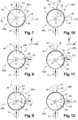
- the first half 20A of the disc is then brought by the motor 18 into said active arrangement as illustrated by the Figures 7 to 9 .
- the second half 20A of the disc is then brought by the motor 18 into said active arrangement as illustrated by the Figures 10 to 12 .
- the change of operating mode of the valve 10 is obtained by a 180° rotation of the disk 20 in order to selectively arrange, in said active arrangement, the first half 20A or the second half 20B of the disk 20 depending on whether the valve 10 is used in the first operating mode or the second operating mode.
- the first half 20A and the second half 20B of the disk 20 each comprise a circulation sector and at least one closure sector which are respectively configured to control, in said active arrangement, the circulation of the fluid.
- the first half 20A of the disk has a circulation sector 44 and an obturation sector 46.
- the circulation sector 44 of the first half 20A of the disk 20 is delimited circumferentially on either side by an edge of the edge 38, respectively an edge 48 and an edge 50.
- edge 48 and the edge 50 delimiting the sector 44 of circulation of the first half 20A of the disk 20 extend along a rectilinear, vertically straight profile.
- the edge profile could have a different geometric shape, for example curvilinear or following a broken line, as will be explained later with reference to Figures 13 and 14 .
- the edge 50 When the first half 20A of the disk 20 occupies the active arrangement determined relative to the second and third channels V2 and V3, the edge 50 then constitutes a so-called “regulating” edge.
- the second channel V2 remaining constantly open, it is the regulating edge 50 which participates in the regulation of the flow rate of the third channel V3 of circulation of the fluid because, depending on the angular position of the disk 20, its profile determines - in combination with the orifice 35 - the passage section of the fluid.
- the second half 20B of the disk comprises a circulation sector 52 and at least one obturation sector, here two obturation sectors which are separated by said circulation sector 52.
- the second half 20B comprises a first shutter sector 54 for permanently closing the second channel V2 and a second shutter sector 56 for selectively closing the third regulated channel V3.
- the circulation sector 52 of the second half 20B of the disk 20 is delimited circumferentially on either side by an edge of the edge 38, respectively an edge 58 and an edge 60.
- edge 58 and the edge 60 delimiting the circulation sector 52 of the second half 20B of the disk 20 extend along a rectilinear, vertically straight profile.
- the edge 60 When the second half 20B of the disk 20 occupies the active arrangement determined relative to the second and third paths V2 and V3, the edge 60 then constitutes a so-called “regulating” edge for regulating the third path V3 of fluid circulation.
- the regulating edge 60 is located between the circulation sector 52 and the second obturation sector 56.
- the regulating edge 60 participates in regulating the flow rate of the third fluid circulation path V3, like the regulating edge 50 in the first operating mode.
- the flow rate of the third channel V3 can be regulated by acting on the angular position of the disk 20, said third channel V3 is completely open when the circulation sector 52 is positioned radially in coincidence with the orifice 35 or closed when the second obturation sector 56 is positioned radially in coincidence with the orifice 35.
- the other half 20B of the disk 20 located diametrically opposite is then not used functionally. Indeed, in the first operating mode, the second half 20B is in an inactive arrangement.
- the circulation sector 44 of the first half 20A is configured so that the second path V2 remains permanently open to the circulation of the fluid when the complementary shutter sector 46 is rotated to regulate the circulation through the third path V3.
- the shutter sector 46 is therefore likely to occupy in in addition to an extreme closed position, at least one intermediate regulation position and an extreme open position.
- the circulation sector 44 ensures, by its configuration, the fact that the second channel V2 remains constantly open.
- the circulation sector 44 of the first half 20A has an angle ( ⁇ ) whose value is notably determined as a function of the angle between the second lane V2 and the third lane V3 and as a function of the angle corresponding to the travel between the extreme closed and open positions.
- the second lane V2 and the third lane V3 being arranged orthogonally to each other, the value of the angle ( ⁇ ) of the circulation sector 44 of the first half 20A is here greater than 90°.
- the minimum value of the angle ( ⁇ ) of the circulation sector 44 of the first half 20A is determined by the extreme opening position of the shutter sector 46 which, represented on the figure 9 , corresponds to the determining position to be considered to constantly guarantee total opening of the second circulation path V2, independently of the fluid regulation carried out for the third path V3.
- FIG. 7 represents half 20A of the disk 20 in an angular position in which the shutter sector 46 occupies said extreme closing position.
- the shutter sector 46 is placed opposite the orifice 35 of the third channel V3 so that the fluid cannot circulate there.
- the regulating edge 50 located at the junction of the circulation sector 44 and the closure sector 46 is arranged, in this extreme closed position, in the vicinity of the orifice 35 of the third channel V3, on the side which is closest to the second channel V2.
- FIG 8 represents half 20A of the disk 20 in another angular position in which the shutter sector 46 occupies one of the intermediate regulation positions located between said extreme closing position illustrated by the figure 7 and the extreme opening position illustrated by the figure 9 .
- the driving of the disk 20 by the motor 18 around the axis O in a clockwise direction causes the displacement of the shutter sector 46 from the extreme closed position to the extreme open position, that is to say an opening of the circulation of the fluid through the third channel V3.
- the intermediate regulation position shown on the figure 8 is here halfway between said extreme closed position and the extreme open position.
- This intermediate regulation position between 0 and 100% of the fluid circulation thus corresponds to a circulation of the fluid with a flow rate of 50% towards the third channel V3.
- the regulating edge 50 having a vertically rectilinear profile then divides the circular passage section of the orifice 35 into two.
- the shutter sector 46 being in the intermediate regulation position, the fluid admitted at the inlet of the valve 10 by the first channel V1 (permanently open) then flows, on the one hand, through the second circulation channel V2 and, on the other hand, through the third channel V3 with a flow rate determined by the intermediate position of the shutter sector 46.
- FIG. 9 represents half 20A of the disk 20 in an angular position in which the shutter sector 46 occupies said extreme opening position.
- the shutter sector 46 is angularly offset relative to the orifice 35 of the third channel V3 so as to no longer be radially coincident with it, so that the fluid can flow freely towards the third channel V3.
- the regulating edge 50 located at the junction of the circulation sector 44 and the closure sector 46 is arranged, in this extreme opening position, on the diametrically opposite side of the orifice 35 compared to that occupied in the extreme closing position.
- the opening (or closing) stroke to fully open the flow of fluid through the third channel V3 corresponds to an angle ( ⁇ ) which is determined by the geometric characteristics of the orifice 35.
- the opening stroke corresponds to the passage of the shutter sector 46 from the extreme closing position ( figure 7 ) to the extreme opening position ( figure 9 ), the value of the angle ( ⁇ ) can for example be determined by considering the regulating edge 50 as a reference.
- the angle ( ⁇ ) of the circulation sector of half 20A of the disk thus has a value which corresponds at least to the sum of the angle ( ⁇ ) with the angle between the channels V2 and V3 which is here equal to 90°.
- the valve By keeping the second channel V2 in the closed state, there is no circulation of fluid through the heat exchanger dedicated to the EHR.
- the valve is thus in a so-called "summer" operating mode for which the EHR requirement is zero.
- the second half 20B On the Figures 10 to 12 corresponding to this second mode of operation, the second half 20B is brought into the vicinity of the second channel V2 and third channel V3 in order to occupy said active arrangement.
- the change between the two operating modes is obtained by a 180° rotation of the disk 20 to bring the second half 20B into active disposition, in place of the first half 20A which succeeds it in inactive disposition until the next change of operating mode.
- the second half 20B of the disk 20 is configured as follows.
- the circulation sector 52 of the second half 20B is configured to allow the circulation of the fluid through the third path V3 to be regulated, in particular to allow the third path V3 of fluid circulation to be completely opened.
- the circulation sector 52 extends at least at an angle at least equal to the angle ( ⁇ ) since it is determined in relation to the orifice 35 of the third channel V3, in particular here its diameter.
- the value of the angle ( ⁇ ) is substantially equal to that of the aforementioned angle ( ⁇ ) corresponding to the opening and closing stroke of the third channel V3, each being determined as a function of the geometric characteristics of the orifice 35.
- the second shutter sector 56 of the second half 20B is configured to allow the circulation of the fluid through the third path V3 to be regulated, more particularly to allow the third fluid circulation path V3 to be completely closed.
- the second closing sector 56 also extends at least at this same angle ( ⁇ ) determined relative to the orifice 35 in order to be able to completely close the third channel V3.
- the first circulation sector 54 is configured to constantly close the second fluid circulation path V2.
- the first circulation sector 54 extends angularly so as to close the orifice 34 of the second channel V2 when the half 20B of the disk 20 is moved along an opening (or closing) stroke to selectively position in coincidence with the orifice 35 either the second closing sector 56 or the circulation sector 52.
- the second shutter sector 56 is capable of occupying an extreme closing position, at least one intermediate regulation position and an extreme opening position.
- FIG 10 represents half 20B of the disk 20 in an angular position in which the second shutter sector 56 occupies an extreme closed position.
- the second shutter sector 56 is placed radially opposite the orifice 35 of the third channel V3 so that said channel V3 is closed to the circulation of fluid.
- figure 11 represents the half 20B of the disk 20 in an angular position in which the second shutter sector 56 occupies one of the intermediate regulation positions angularly included between the extreme closing position illustrated by the figure 10 and the extreme opening position illustrated by the figure 12 .
- the driving of the disk 20 by the motor 18 around the axis O in a clockwise direction causes the movement of the second shutter sector 56 from the extreme closed position to the extreme open position, that is to say causes an opening of the circulation of the fluid through the third channel V3 as illustrated by the arrow on the figure. figure 11 .
- the intermediate regulation position shown on the figure 11 is here halfway between said extreme closed position and the extreme open position.
- This intermediate regulation position between 0 and 100% of the fluid circulation thus corresponds to a circulation of the fluid with a flow rate of 50% towards the third channel V3.
- the regulating edge 60 which comprises the edge 38 having a vertically rectilinear profile then divides the circular passage section of the orifice 35 in two.
- the second shutter sector 56 being in the intermediate regulation position, the fluid admitted at the inlet of the valve 10 by the first channel V1 (permanently open) then flows through the third channel V3 with a more or less significant flow rate determined by the intermediate position of the second shutter sector 56.
- FIG 12 represents the second half 20B of the disk 20 in an angular position in which the second shutter sector 56 occupies said extreme opening position.
- the second shutter sector 56 is angularly offset relative to the orifice 35 of the third channel V3.
- the circulation sector 52 adjacent to the second obturation sector 56, is then positioned in coincidence with the orifice 35 so that the fluid can flow towards the third channel V3 which is fully open.
- the regulating edge 60 of the edge 38 located in the second half 20B passes from one side of the orifice 35 to the other side, diametrically opposite.
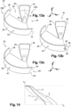
- FIGS. 13 a, b and c are perspective views which, analogous to the figure 4 , represent, without limitation, other examples of a profile of a regulating edge.
- Each of these profile variants is likely to apply to the regulating edge 50 of the obturation sector 44 of the first half 20A and/or to the regulating edge 60 of the second obturation sector 56 of the second half 20B of the disk.
- the regulating edge 50 and the regulating edge 60 have an identical profile, namely vertically straight or rectilinear, but this profile could be different in particular since each of these edges intervenes in a different operating mode of the valve 10.
- the regulating edge 50 of the shutter sector 44 of the first half 20A is used in the first operating mode while the regulating edge 60 of the second shutter sector 56 of the second half 20B is used in the second operating mode.
- FIG. 13a represents a regulating edge 70 having a beveled profile, the edge extending in a straight line but obliquely to the vertical orientation.
- FIG. 13b represents a regulating edge 80 having a profile comprising two bevels in opposite directions, respectively a first bevel 82 and a second bevel 84, said profile corresponding to the shape of a circumflex accent.
- the first bevel 82 enters the edge 38 of the disk 20 then, for example here at half the height of said edge 38, the second bevel 84 goes back in the opposite direction, towards the adjacent traffic sector.
- FIG. 13c represents a regulating edge 90 having a profile comprising a straight edge 92 which extends vertically then a bevel 94 which extends obliquely to the vicinity of the wall 36 of the disk 20.
- the profile of the regulating edge can take multiple geometric shapes, including curvilinear ones.
- the regulating edge profile is advantageously determined by calculation in order to be optimized.
- the profile is determined using a mathematical function so that the opening section, for a given rotation angle, corresponds exactly to the desired engine operating points, such as an operating point established according to two parameters which are the engine speed and the engine load, for example those of an internal combustion engine in the case of the application of the valve 10 to an exhaust gas recirculation circuit.
- the graph obtained by representing the angle of rotation of the disk as a function of the fluid passage section is not a straight line.
- the different curves identified a, b and c correspond respectively to the profile of the regulating edge represented on the Figures 13 a, b, c and for the curve d to that of the figure 4 .
- valve 10 As previously indicated, the valve 10 according to the embodiment which has just been described is advantageously used in a circuit (not shown) for recirculating exhaust gases from an internal combustion engine of a motor vehicle.
- EGR exhaust gas recirculation
- exhaust gas recirculation helps to limit NOx emissions (in proportion to the fraction of exhaust gases recycled) but nevertheless reduces engine performance.
- Low pressure recirculation involves taking the exhaust gases after the turbine, downstream of the particulate filter, to reinject them upstream of the charge air compressor (alternatively upstream of the charge air cooler located downstream of the compressor) while high pressure recirculation involves taking the exhaust gases upstream of the turbine to reinject them downstream of the compressor.
- EGR exhaust gas recirculation circuit
- cooling the air advantageously increases its density, allowing more fuel to be injected, with the final benefit of better mixing and therefore better engine performance.
- the exhaust gas recirculation circuit includes at least one recirculation line having one end connected to an engine exhaust circuit and having another end connected to an engine intake circuit.
- valve 10 is arranged in said at least one recirculation pipe of the exhaust gas recirculation circuit or “EGR” pipe so that the first path V1 forming an inlet is connected to the exhaust while the third regulated path V3 is connected to the engine intake.
- the exhaust gas recirculation circuit comprises at least one further line for performing an “EHR” function.
- the other “EHR” pipe then has one end connected to the second channel V2 controlled in cut-off (on/off) and another end connected to a heat exchanger in order to transfer calories from the exhaust gases to the liquid (cooling).
- valve 10 is then arranged in the recirculation circuit so that the first exhaust gas inlet path V1 is connected to the engine exhaust and the outlet paths V2 and V3 are respectively connected to the EHR pipe and the EGR pipe.
Landscapes
- Engineering & Computer Science (AREA)
- General Engineering & Computer Science (AREA)
- Mechanical Engineering (AREA)
- Chemical & Material Sciences (AREA)
- Combustion & Propulsion (AREA)
- Multiple-Way Valves (AREA)
Claims (9)
- Ventil (10) für einen Fluidkreislauf des Typs eines Rezirkulationskreislaufs von Abgas eines Verbrennungsmotors, umfassend einen Körper (12), der aus mindestens einem ersten Gehäuse (14), mit dem ein erster Fluidzirkulationskanal (V1) verbunden ist, einem zweiten Gehäuse (16), mit dem ein zweiter Fluidzirkulationskanal (V2) und ein dritter Fluidzirkulationskanal (V3) verbunden sind, besteht, und wobei ein Steuerelement (20), das dicht montiert ist, zum Einnehmen unterschiedlicher Positionen um eine Achse (O) rotierend angetrieben wird, um die Fluidzirkulation zwischen dem ersten Fluidzirkulationskanal (V1) und dem zweiten und dritten Fluidzirkulationskanal (V2, V3) zu steuern,
wobei der erste Zirkulationskanal (V1) für die Fluidzirkulation permanent offen ist, wobei das Steuerelement (20) eine Scheibe ist, die mindestens umfasst:- einen ersten Teil (20A), der, verknüpft mit einem ersten Betriebsmodus des Ventils, zum ständigen Öffnen der Fluidzirkulation durch den zweiten Zirkulationskanal (V2) und zum gleichzeitigen Regeln der Fluidzirkulation durch den dritten Zirkulationskanal (V3) konfiguriert ist, und- einen zweiten Teil (20B), der, verknüpft mit einem zweiten Betriebsmodus des Ventils, zum ständigen Schließen der Fluidzirkulation durch den zweiten Zirkulationskanal (V2) und zum gleichzeitigen Regeln der Fluidzirkulation durch den dritten Zirkulationskanal (V3) konfiguriert ist, dadurch gekennzeichnet, dass der erste Kanal (V1) des Ventils (10) in Bezug auf einen Rand (25) des ersten Gehäuses, genannt das untere Gehäuse, radial angeschlossen ist, also orthogonal zu der Rotationsachse (O) des zweiten Kanals (V2), und der dritte Fluidzirkulationskanal (V3) an den Rand (27) des zweiten Gehäuses (16), genannt das obere Gehäuse, radial angeschlossen ist, also orthogonal zu der Rotationsachse (O), und dass die Scheibe (20) eine Wand (36), die sich in einer Ebene (L, T) horizontal erstreckt, und einen zylindrischen Rand (38), der sich von dem äußeren radialen Umfang der Wand (36) vertikal nach unten erstreckt, umfasst, wobei der zylindrische Rand (38) der Scheibe (20) eine Außenoberfläche (40) umfasst, derart, dass die Dichtheit durch einen eingestellten seitlichen Kontakt zwischen einer Innenoberfläche (30) des zweiten Gehäuses (16) und der Außenoberfläche (40) des Steuerelements (20) gewährleistet ist. - Ventil nach Anspruch 1, dadurch gekennzeichnet, dass der erste Teil (20A) aus einer Hälfte der Scheibe (20) ausgebildet wird und der zweite Teil (20B) aus der anderen Hälfte der Scheibe (20) ausgebildet wird.
- Ventil nach Anspruch 1 oder 2, dadurch gekennzeichnet, dass die Scheibe (20) durch Antriebsmittel (18) zum selektiven Lenken in einer aktiven Verfassung, die relativ zu der Anordnung des zweiten Fluidzirkulationskanals und des dritten Fluidzirkulationskanals (V2, V3) definiert ist, des ersten Teils (20A) der Scheibe (20), wenn das Ventil (10) in dem ersten Betriebsmodus verwendet wird, oder des zweiten Teils (20B) der Scheibe (20), wenn das Ventil (10) in dem zweiten Betriebsmodus verwendet wird, rotierend angetrieben wird.
- Ventil nach Anspruch 3, dadurch gekennzeichnet, dass der erste Teil (20A) der Scheibe (20) einen Zirkulationsbereich (44) und einen Abdichtungsbereich (46) umfasst, die jeweils zum Steuern der Fluidzirkulation konfiguriert sind, wenn, in dem ersten Betriebsmodus des Ventils (10), der erste Teil (20A) in aktiver Verfassung ist.
- Ventil nach Anspruch 4, dadurch gekennzeichnet, dass sich der Zirkulationsbereich (44) des ersten Teils (20A) einem Winkel (α) folgend winkelig erstreckt, dessen Wert zum vollständigen Öffnen der Fluidzirkulation durch den zweiten Kanals (V2) bestimmt wird, wenn der Abdichtungsbereich (46), der komplementär zu dem ersten Teil (20A) ist, zwischen mindestens einer extremen Schließposition und einer extremen Öffnungsposition zum Regeln der Fluidzirkulation in dem dritten Kanal (V3) rotierend angetrieben wird.
- Ventil nach Anspruch 5, dadurch gekennzeichnet, dass der Wert des Winkels (α) des Zirkulationsbereichs (44) des ersten Teils (20A) der Scheibe (20) größer als der Wert des Winkels zwischen dem zweiten Kanal (V2) und dem dritten Kanal (V3) ist.
- Ventil nach Anspruch 3, dadurch gekennzeichnet, dass der zweite Teil (20B) der Scheibe (20) einen Zirkulationsbereich (52) umfasst, der zwischen einem ersten Abdichtungsbereich (54) und einem zweiten Abdichtungsbereich (56) liegt, wobei die Zirkulationsbereiche und die Abdichtungsbereiche jeweils zum Steuern der Fluidzirkulation konfiguriert sind, wenn, in dem zweiten Betriebsmodus des Ventils (10), der zweite Teil (20B) in aktiver Verfassung ist.
- Ventil nach Anspruch 7, dadurch gekennzeichnet, dass der erste Abdichtungsbereich (54) zum Schließen der Fluidzirkulation durch den zweiten Kanal (V2) konfiguriert ist, wenn der zweite Abdichtungsbereich (56) zwischen einer extremen Schließposition und einer extremen Öffnungsposition zum Regeln der Fluidzirkulation in dem dritten Kanal (V3) rotierend angetrieben wird.
- Rezirkulationskreislauf von Abgasen eines Verbrennungsmotors eines Kraftfahrzeugs, umfassend mindestens eine Rezirkulationsleitung mindestens eines Teils der Abgase, deren eines Ende mit einem Auspuffkreislauf des Motors verbunden ist und deren anderes Ende mit einem Einlasskreislauf des Motors verbunden ist, dadurch gekennzeichnet, dass die Rezirkulationsleitung des Kreislaufs mindestens ein Ventil (10) nach einem der vorstehenden Ansprüche umfasst.
Applications Claiming Priority (2)
| Application Number | Priority Date | Filing Date | Title |
|---|---|---|---|
| FR1759866A FR3072753B1 (fr) | 2017-10-19 | 2017-10-19 | Vanne pour un circuit de fluide, notamment un circuit de recirculation des gaz d'echappement d'un moteur |
| PCT/EP2018/078638 WO2019077075A1 (fr) | 2017-10-19 | 2018-10-18 | Vanne pour un circuit de fluide, notamment un circuit de recirculation des gaz d'échappement d'un moteur |
Publications (2)
| Publication Number | Publication Date |
|---|---|
| EP3698074A1 EP3698074A1 (de) | 2020-08-26 |
| EP3698074B1 true EP3698074B1 (de) | 2024-10-02 |
Family
ID=60450911
Family Applications (1)
| Application Number | Title | Priority Date | Filing Date |
|---|---|---|---|
| EP18786785.8A Active EP3698074B1 (de) | 2017-10-19 | 2018-10-18 | Ventil für einen flüssigkeitskreislauf, insbesondere für einen abgasrückführkreislauf |
Country Status (3)
| Country | Link |
|---|---|
| EP (1) | EP3698074B1 (de) |
| FR (1) | FR3072753B1 (de) |
| WO (2) | WO2019077075A1 (de) |
Families Citing this family (2)
| Publication number | Priority date | Publication date | Assignee | Title |
|---|---|---|---|---|
| CN113251179B (zh) * | 2021-05-18 | 2025-08-08 | 四川芯智热控技术有限公司 | 一种串联式车用热管理集成水阀及流道控制方法 |
| CN115674990B (zh) * | 2021-07-28 | 2025-10-17 | 上汽通用汽车有限公司 | 阀、汽车空调系统和汽车 |
Citations (1)
| Publication number | Priority date | Publication date | Assignee | Title |
|---|---|---|---|---|
| US7213587B2 (en) * | 2004-08-19 | 2007-05-08 | Pierburg Gmbh | Adjustable two-way valve device for a combustion engine |
Family Cites Families (5)
| Publication number | Priority date | Publication date | Assignee | Title |
|---|---|---|---|---|
| DE4431711A1 (de) * | 1994-09-06 | 1996-03-07 | Bosch Gmbh Robert | Vorrichtung zur Regelung der Leerlaufdrehzahl einer Brennkraftmaschine |
| FR2827357B1 (fr) * | 2001-07-11 | 2003-12-12 | Valeo Thermique Moteur Sa | Vanne de commande pour un circuit de circulation de fluide, en particulier pour un circuit de refroidissement d'un moteur |
| FR2827356B1 (fr) * | 2001-07-11 | 2004-11-05 | Valeo Thermique Moteur Sa | Vanne de commande a disques pour circuit de circulation fluide |
| JP6003716B2 (ja) * | 2012-04-17 | 2016-10-05 | 株式会社デンソー | 流路切替装置 |
| WO2015004497A1 (en) * | 2013-07-10 | 2015-01-15 | Renault Trucks | Turbocharged engine arrangement with exhaust gases recirculation installations and rotary flow control valve |
-
2017
- 2017-10-19 FR FR1759866A patent/FR3072753B1/fr active Active
-
2018
- 2018-10-18 WO PCT/EP2018/078638 patent/WO2019077075A1/fr not_active Ceased
- 2018-10-18 WO PCT/EP2018/078610 patent/WO2019077064A1/fr not_active Ceased
- 2018-10-18 EP EP18786785.8A patent/EP3698074B1/de active Active
Patent Citations (1)
| Publication number | Priority date | Publication date | Assignee | Title |
|---|---|---|---|---|
| US7213587B2 (en) * | 2004-08-19 | 2007-05-08 | Pierburg Gmbh | Adjustable two-way valve device for a combustion engine |
Also Published As
| Publication number | Publication date |
|---|---|
| WO2019077064A1 (fr) | 2019-04-25 |
| FR3072753B1 (fr) | 2019-11-29 |
| FR3072753A1 (fr) | 2019-04-26 |
| EP3698074A1 (de) | 2020-08-26 |
| WO2019077075A1 (fr) | 2019-04-25 |
Similar Documents
| Publication | Publication Date | Title |
|---|---|---|
| EP2850298B1 (de) | Ventil zum steuerung eines flüssigkeitsstroms mit einer drehverschlussvorrichtung | |
| EP3698074B1 (de) | Ventil für einen flüssigkeitskreislauf, insbesondere für einen abgasrückführkreislauf | |
| FR2930281A1 (fr) | Ligne d'echappement de vehicule automobile avec conduit de recyclage. | |
| FR2923886A1 (fr) | Vanne pour circuit d'alimentation en air d'un moteur de vehicule automobile, circuit comportant une telle vanne et procede de commande d'un moteur utilisant un tel circuit | |
| FR2920853A1 (fr) | Vanne pour circuit d'alimentation en air d'un moteur de vehicule automobile, circuit comportant une telle vanne et procede de commande d'un moteur utilisant un tel circuit | |
| WO2012001286A1 (fr) | Vanne de circulation de fluide | |
| EP2786007B1 (de) | Ventil für eine gasströmungsschaltung in einem fahrzeug | |
| FR2947319A1 (fr) | Vanne a boisseau, boisseau pour une telle vanne et circuit d'admission de gaz dans un moteur thermique de vehicule avec une telle vanne | |
| EP2906859A1 (de) | Ventil, insbesondere für eine brennkraftmaschine | |
| WO2013171404A1 (fr) | Vanne de circulation de fluide, notamment pour véhicule automobile, et dispositif de conditionnement thermique comprenant une telle vanne | |
| WO2018234698A1 (fr) | Système de combustion à volume constant comprenant un élément d'obturation tournant à lumières segmentées | |
| EP2850299A1 (de) | Flüssigkeitsdurchlaufventil, insbesondere für ein kraftfahrzeug, und temperaturregelungsvorrichtung mit solch einem ventil | |
| EP3217007B1 (de) | Ventil zur gleichzeitigen regelung von zwei fluidströmen, insbesondere für die dosierung von rückgeführten gasen in einem verbrennungsmotor | |
| EP2850349A1 (de) | Flüssigkeitsumlaufventil | |
| WO2011076891A1 (fr) | Vanne destinee, notamment, a etre implantee dans un circuit d'admission d'air d'un moteur thermique | |
| FR2910541A1 (fr) | Systeme d'admission de gaz pour la generation d'ecoulement de rotation energetique de tumble | |
| EP3175100B1 (de) | Zweitaktbrennkraftmaschine eines kraftfahrzeugs mit verdehten einlasskanälen mit seitlichen geraden kanten | |
| FR3068074B1 (fr) | Systeme de combustion a volume constant avec collecteur d'echappement cloisonne | |
| WO2015170020A2 (fr) | Moteur thermique deux temps de vehicule automobile a lumieres d'admission vrillees | |
| FR2801638A1 (fr) | Systeme d'admission de gaz dans un moteur a combustion | |
| EP2844900A1 (de) | Motorregelventil mit verbesserter öffnung | |
| FR3059051A1 (fr) | Dispositif de conditionnement thermique de fluide pour moteur a combustion | |
| FR2928971A1 (fr) | Dispositif d'admission d'air dans un cylindre d'un moteur a combustion interne | |
| FR2924780A1 (fr) | Conduit d'ecoulement de gaz avec obturateur pour vehicule automobile | |
| FR2819014A1 (fr) | Systeme d'admission de gaz dans un cylindre d'un moteur a combustion |
Legal Events
| Date | Code | Title | Description |
|---|---|---|---|
| STAA | Information on the status of an ep patent application or granted ep patent |
Free format text: STATUS: UNKNOWN |
|
| STAA | Information on the status of an ep patent application or granted ep patent |
Free format text: STATUS: THE INTERNATIONAL PUBLICATION HAS BEEN MADE |
|
| PUAI | Public reference made under article 153(3) epc to a published international application that has entered the european phase |
Free format text: ORIGINAL CODE: 0009012 |
|
| STAA | Information on the status of an ep patent application or granted ep patent |
Free format text: STATUS: REQUEST FOR EXAMINATION WAS MADE |
|
| 17P | Request for examination filed |
Effective date: 20200403 |
|
| AK | Designated contracting states |
Kind code of ref document: A1 Designated state(s): AL AT BE BG CH CY CZ DE DK EE ES FI FR GB GR HR HU IE IS IT LI LT LU LV MC MK MT NL NO PL PT RO RS SE SI SK SM TR |
|
| AX | Request for extension of the european patent |
Extension state: BA ME |
|
| RAP1 | Party data changed (applicant data changed or rights of an application transferred) |
Owner name: RENAULT S.A.S |
|
| DAV | Request for validation of the european patent (deleted) | ||
| DAX | Request for extension of the european patent (deleted) | ||
| RAP3 | Party data changed (applicant data changed or rights of an application transferred) |
Owner name: RENAULT S.A.S |
|
| STAA | Information on the status of an ep patent application or granted ep patent |
Free format text: STATUS: EXAMINATION IS IN PROGRESS |
|
| 17Q | First examination report despatched |
Effective date: 20220628 |
|
| RAP3 | Party data changed (applicant data changed or rights of an application transferred) |
Owner name: RENAULT S.A.S |
|
| P01 | Opt-out of the competence of the unified patent court (upc) registered |
Effective date: 20230608 |
|
| GRAP | Despatch of communication of intention to grant a patent |
Free format text: ORIGINAL CODE: EPIDOSNIGR1 |
|
| STAA | Information on the status of an ep patent application or granted ep patent |
Free format text: STATUS: GRANT OF PATENT IS INTENDED |
|
| RIC1 | Information provided on ipc code assigned before grant |
Ipc: F02M 26/71 20160101ALI20240326BHEP Ipc: F02M 26/70 20160101ALI20240326BHEP Ipc: F02M 1/00 20060101ALI20240326BHEP Ipc: F02M 26/00 20160101ALI20240326BHEP Ipc: F16K 11/085 20060101ALI20240326BHEP Ipc: F16K 11/076 20060101AFI20240326BHEP |
|
| INTG | Intention to grant announced |
Effective date: 20240426 |
|
| RAP3 | Party data changed (applicant data changed or rights of an application transferred) |
Owner name: RENAULT S.A.S. |
|
| GRAS | Grant fee paid |
Free format text: ORIGINAL CODE: EPIDOSNIGR3 |
|
| GRAA | (expected) grant |
Free format text: ORIGINAL CODE: 0009210 |
|
| STAA | Information on the status of an ep patent application or granted ep patent |
Free format text: STATUS: THE PATENT HAS BEEN GRANTED |
|
| AK | Designated contracting states |
Kind code of ref document: B1 Designated state(s): AL AT BE BG CH CY CZ DE DK EE ES FI FR GB GR HR HU IE IS IT LI LT LU LV MC MK MT NL NO PL PT RO RS SE SI SK SM TR |
|
| REG | Reference to a national code |
Ref country code: GB Ref legal event code: FG4D Free format text: NOT ENGLISH |
|
| REG | Reference to a national code |
Ref country code: CH Ref legal event code: EP |
|
| REG | Reference to a national code |
Ref country code: DE Ref legal event code: R096 Ref document number: 602018074980 Country of ref document: DE |
|
| REG | Reference to a national code |
Ref country code: IE Ref legal event code: FG4D Free format text: LANGUAGE OF EP DOCUMENT: FRENCH |
|
| REG | Reference to a national code |
Ref country code: LT Ref legal event code: MG9D |
|
| REG | Reference to a national code |
Ref country code: NL Ref legal event code: MP Effective date: 20241002 |
|
| REG | Reference to a national code |
Ref country code: AT Ref legal event code: MK05 Ref document number: 1728728 Country of ref document: AT Kind code of ref document: T Effective date: 20241002 |
|
| PG25 | Lapsed in a contracting state [announced via postgrant information from national office to epo] |
Ref country code: NL Free format text: LAPSE BECAUSE OF FAILURE TO SUBMIT A TRANSLATION OF THE DESCRIPTION OR TO PAY THE FEE WITHIN THE PRESCRIBED TIME-LIMIT Effective date: 20241002 |
|
| PG25 | Lapsed in a contracting state [announced via postgrant information from national office to epo] |
Ref country code: NL Free format text: LAPSE BECAUSE OF FAILURE TO SUBMIT A TRANSLATION OF THE DESCRIPTION OR TO PAY THE FEE WITHIN THE PRESCRIBED TIME-LIMIT Effective date: 20241002 |
|
| PG25 | Lapsed in a contracting state [announced via postgrant information from national office to epo] |
Ref country code: HR Free format text: LAPSE BECAUSE OF FAILURE TO SUBMIT A TRANSLATION OF THE DESCRIPTION OR TO PAY THE FEE WITHIN THE PRESCRIBED TIME-LIMIT Effective date: 20241002 Ref country code: PT Free format text: LAPSE BECAUSE OF FAILURE TO SUBMIT A TRANSLATION OF THE DESCRIPTION OR TO PAY THE FEE WITHIN THE PRESCRIBED TIME-LIMIT Effective date: 20250203 Ref country code: IS Free format text: LAPSE BECAUSE OF FAILURE TO SUBMIT A TRANSLATION OF THE DESCRIPTION OR TO PAY THE FEE WITHIN THE PRESCRIBED TIME-LIMIT Effective date: 20250202 |
|
| PG25 | Lapsed in a contracting state [announced via postgrant information from national office to epo] |
Ref country code: FI Free format text: LAPSE BECAUSE OF FAILURE TO SUBMIT A TRANSLATION OF THE DESCRIPTION OR TO PAY THE FEE WITHIN THE PRESCRIBED TIME-LIMIT Effective date: 20241002 |
|
| PG25 | Lapsed in a contracting state [announced via postgrant information from national office to epo] |
Ref country code: BG Free format text: LAPSE BECAUSE OF FAILURE TO SUBMIT A TRANSLATION OF THE DESCRIPTION OR TO PAY THE FEE WITHIN THE PRESCRIBED TIME-LIMIT Effective date: 20241002 |
|
| PG25 | Lapsed in a contracting state [announced via postgrant information from national office to epo] |
Ref country code: ES Free format text: LAPSE BECAUSE OF FAILURE TO SUBMIT A TRANSLATION OF THE DESCRIPTION OR TO PAY THE FEE WITHIN THE PRESCRIBED TIME-LIMIT Effective date: 20241002 |
|
| PG25 | Lapsed in a contracting state [announced via postgrant information from national office to epo] |
Ref country code: NO Free format text: LAPSE BECAUSE OF FAILURE TO SUBMIT A TRANSLATION OF THE DESCRIPTION OR TO PAY THE FEE WITHIN THE PRESCRIBED TIME-LIMIT Effective date: 20250102 |
|
| PG25 | Lapsed in a contracting state [announced via postgrant information from national office to epo] |
Ref country code: LV Free format text: LAPSE BECAUSE OF FAILURE TO SUBMIT A TRANSLATION OF THE DESCRIPTION OR TO PAY THE FEE WITHIN THE PRESCRIBED TIME-LIMIT Effective date: 20241002 Ref country code: AT Free format text: LAPSE BECAUSE OF FAILURE TO SUBMIT A TRANSLATION OF THE DESCRIPTION OR TO PAY THE FEE WITHIN THE PRESCRIBED TIME-LIMIT Effective date: 20241002 Ref country code: GR Free format text: LAPSE BECAUSE OF FAILURE TO SUBMIT A TRANSLATION OF THE DESCRIPTION OR TO PAY THE FEE WITHIN THE PRESCRIBED TIME-LIMIT Effective date: 20250103 |
|
| PG25 | Lapsed in a contracting state [announced via postgrant information from national office to epo] |
Ref country code: CZ Free format text: LAPSE BECAUSE OF FAILURE TO SUBMIT A TRANSLATION OF THE DESCRIPTION OR TO PAY THE FEE WITHIN THE PRESCRIBED TIME-LIMIT Effective date: 20241002 Ref country code: PL Free format text: LAPSE BECAUSE OF FAILURE TO SUBMIT A TRANSLATION OF THE DESCRIPTION OR TO PAY THE FEE WITHIN THE PRESCRIBED TIME-LIMIT Effective date: 20241002 |
|
| PG25 | Lapsed in a contracting state [announced via postgrant information from national office to epo] |
Ref country code: RS Free format text: LAPSE BECAUSE OF FAILURE TO SUBMIT A TRANSLATION OF THE DESCRIPTION OR TO PAY THE FEE WITHIN THE PRESCRIBED TIME-LIMIT Effective date: 20250102 |
|
| REG | Reference to a national code |
Ref country code: CH Ref legal event code: PL |
|
| PG25 | Lapsed in a contracting state [announced via postgrant information from national office to epo] |
Ref country code: SM Free format text: LAPSE BECAUSE OF FAILURE TO SUBMIT A TRANSLATION OF THE DESCRIPTION OR TO PAY THE FEE WITHIN THE PRESCRIBED TIME-LIMIT Effective date: 20241002 |
|
| REG | Reference to a national code |
Ref country code: DE Ref legal event code: R097 Ref document number: 602018074980 Country of ref document: DE |
|
| PG25 | Lapsed in a contracting state [announced via postgrant information from national office to epo] |
Ref country code: MC Free format text: LAPSE BECAUSE OF FAILURE TO SUBMIT A TRANSLATION OF THE DESCRIPTION OR TO PAY THE FEE WITHIN THE PRESCRIBED TIME-LIMIT Effective date: 20241002 |
|
| PG25 | Lapsed in a contracting state [announced via postgrant information from national office to epo] |
Ref country code: DK Free format text: LAPSE BECAUSE OF FAILURE TO SUBMIT A TRANSLATION OF THE DESCRIPTION OR TO PAY THE FEE WITHIN THE PRESCRIBED TIME-LIMIT Effective date: 20241002 |
|
| PG25 | Lapsed in a contracting state [announced via postgrant information from national office to epo] |
Ref country code: LU Free format text: LAPSE BECAUSE OF NON-PAYMENT OF DUE FEES Effective date: 20241018 Ref country code: BE Free format text: LAPSE BECAUSE OF NON-PAYMENT OF DUE FEES Effective date: 20241031 |
|
| PG25 | Lapsed in a contracting state [announced via postgrant information from national office to epo] |
Ref country code: EE Free format text: LAPSE BECAUSE OF FAILURE TO SUBMIT A TRANSLATION OF THE DESCRIPTION OR TO PAY THE FEE WITHIN THE PRESCRIBED TIME-LIMIT Effective date: 20241002 |
|
| PG25 | Lapsed in a contracting state [announced via postgrant information from national office to epo] |
Ref country code: CH Free format text: LAPSE BECAUSE OF NON-PAYMENT OF DUE FEES Effective date: 20241031 |
|
| PG25 | Lapsed in a contracting state [announced via postgrant information from national office to epo] |
Ref country code: RO Free format text: LAPSE BECAUSE OF FAILURE TO SUBMIT A TRANSLATION OF THE DESCRIPTION OR TO PAY THE FEE WITHIN THE PRESCRIBED TIME-LIMIT Effective date: 20241002 |
|
| PG25 | Lapsed in a contracting state [announced via postgrant information from national office to epo] |
Ref country code: SK Free format text: LAPSE BECAUSE OF FAILURE TO SUBMIT A TRANSLATION OF THE DESCRIPTION OR TO PAY THE FEE WITHIN THE PRESCRIBED TIME-LIMIT Effective date: 20241002 |
|
| PG25 | Lapsed in a contracting state [announced via postgrant information from national office to epo] |
Ref country code: IT Free format text: LAPSE BECAUSE OF FAILURE TO SUBMIT A TRANSLATION OF THE DESCRIPTION OR TO PAY THE FEE WITHIN THE PRESCRIBED TIME-LIMIT Effective date: 20241002 |
|
| REG | Reference to a national code |
Ref country code: BE Ref legal event code: MM Effective date: 20241031 |
|
| PLBE | No opposition filed within time limit |
Free format text: ORIGINAL CODE: 0009261 |
|
| STAA | Information on the status of an ep patent application or granted ep patent |
Free format text: STATUS: NO OPPOSITION FILED WITHIN TIME LIMIT |
|
| PG25 | Lapsed in a contracting state [announced via postgrant information from national office to epo] |
Ref country code: SE Free format text: LAPSE BECAUSE OF FAILURE TO SUBMIT A TRANSLATION OF THE DESCRIPTION OR TO PAY THE FEE WITHIN THE PRESCRIBED TIME-LIMIT Effective date: 20241002 |
|
| 26N | No opposition filed |
Effective date: 20250703 |
|
| PG25 | Lapsed in a contracting state [announced via postgrant information from national office to epo] |
Ref country code: IE Free format text: LAPSE BECAUSE OF NON-PAYMENT OF DUE FEES Effective date: 20241018 |
|
| PGFP | Annual fee paid to national office [announced via postgrant information from national office to epo] |
Ref country code: DE Payment date: 20251021 Year of fee payment: 8 |
|
| PGFP | Annual fee paid to national office [announced via postgrant information from national office to epo] |
Ref country code: GB Payment date: 20251022 Year of fee payment: 8 |
|
| PGFP | Annual fee paid to national office [announced via postgrant information from national office to epo] |
Ref country code: FR Payment date: 20251030 Year of fee payment: 8 |
|
| PG25 | Lapsed in a contracting state [announced via postgrant information from national office to epo] |
Ref country code: CY Free format text: LAPSE BECAUSE OF FAILURE TO SUBMIT A TRANSLATION OF THE DESCRIPTION OR TO PAY THE FEE WITHIN THE PRESCRIBED TIME-LIMIT; INVALID AB INITIO Effective date: 20181018 |
|
| PG25 | Lapsed in a contracting state [announced via postgrant information from national office to epo] |
Ref country code: HU Free format text: LAPSE BECAUSE OF FAILURE TO SUBMIT A TRANSLATION OF THE DESCRIPTION OR TO PAY THE FEE WITHIN THE PRESCRIBED TIME-LIMIT; INVALID AB INITIO Effective date: 20181018 |