EP3698038B1 - Injector test machine - Google Patents
Injector test machine Download PDFInfo
- Publication number
- EP3698038B1 EP3698038B1 EP18789583.4A EP18789583A EP3698038B1 EP 3698038 B1 EP3698038 B1 EP 3698038B1 EP 18789583 A EP18789583 A EP 18789583A EP 3698038 B1 EP3698038 B1 EP 3698038B1
- Authority
- EP
- European Patent Office
- Prior art keywords
- injector
- test
- machine
- sleeve
- base member
- Prior art date
- Legal status (The legal status is an assumption and is not a legal conclusion. Google has not performed a legal analysis and makes no representation as to the accuracy of the status listed.)
- Active
Links
Images




Classifications
-
- F—MECHANICAL ENGINEERING; LIGHTING; HEATING; WEAPONS; BLASTING
- F02—COMBUSTION ENGINES; HOT-GAS OR COMBUSTION-PRODUCT ENGINE PLANTS
- F02M—SUPPLYING COMBUSTION ENGINES IN GENERAL WITH COMBUSTIBLE MIXTURES OR CONSTITUENTS THEREOF
- F02M65/00—Testing fuel-injection apparatus, e.g. testing injection timing ; Cleaning of fuel-injection apparatus
-
- F—MECHANICAL ENGINEERING; LIGHTING; HEATING; WEAPONS; BLASTING
- F02—COMBUSTION ENGINES; HOT-GAS OR COMBUSTION-PRODUCT ENGINE PLANTS
- F02M—SUPPLYING COMBUSTION ENGINES IN GENERAL WITH COMBUSTIBLE MIXTURES OR CONSTITUENTS THEREOF
- F02M65/00—Testing fuel-injection apparatus, e.g. testing injection timing ; Cleaning of fuel-injection apparatus
- F02M65/007—Cleaning
- F02M65/008—Cleaning of injectors only
-
- F—MECHANICAL ENGINEERING; LIGHTING; HEATING; WEAPONS; BLASTING
- F02—COMBUSTION ENGINES; HOT-GAS OR COMBUSTION-PRODUCT ENGINE PLANTS
- F02M—SUPPLYING COMBUSTION ENGINES IN GENERAL WITH COMBUSTIBLE MIXTURES OR CONSTITUENTS THEREOF
- F02M65/00—Testing fuel-injection apparatus, e.g. testing injection timing ; Cleaning of fuel-injection apparatus
- F02M65/001—Measuring fuel delivery of a fuel injector
-
- F—MECHANICAL ENGINEERING; LIGHTING; HEATING; WEAPONS; BLASTING
- F02—COMBUSTION ENGINES; HOT-GAS OR COMBUSTION-PRODUCT ENGINE PLANTS
- F02M—SUPPLYING COMBUSTION ENGINES IN GENERAL WITH COMBUSTIBLE MIXTURES OR CONSTITUENTS THEREOF
- F02M2200/00—Details of fuel-injection apparatus, not otherwise provided for
- F02M2200/85—Mounting of fuel injection apparatus
-
- F—MECHANICAL ENGINEERING; LIGHTING; HEATING; WEAPONS; BLASTING
- F02—COMBUSTION ENGINES; HOT-GAS OR COMBUSTION-PRODUCT ENGINE PLANTS
- F02M—SUPPLYING COMBUSTION ENGINES IN GENERAL WITH COMBUSTIBLE MIXTURES OR CONSTITUENTS THEREOF
- F02M2200/00—Details of fuel-injection apparatus, not otherwise provided for
- F02M2200/85—Mounting of fuel injection apparatus
- F02M2200/853—Mounting of fuel injection apparatus involving use of quick-acting mechanism, e.g. clips
-
- F—MECHANICAL ENGINEERING; LIGHTING; HEATING; WEAPONS; BLASTING
- F02—COMBUSTION ENGINES; HOT-GAS OR COMBUSTION-PRODUCT ENGINE PLANTS
- F02M—SUPPLYING COMBUSTION ENGINES IN GENERAL WITH COMBUSTIBLE MIXTURES OR CONSTITUENTS THEREOF
- F02M65/00—Testing fuel-injection apparatus, e.g. testing injection timing ; Cleaning of fuel-injection apparatus
- F02M65/003—Measuring variation of fuel pressure in high pressure line
Definitions
- the present invention relates to a fuel injector test machine.
- Certain diesel injectors are fitted to a range of medium duty passenger vehicle and off-highway applications. Said injectors use an intensifier system to amplify engine oil pressure between 30-300bar to generate high injection pressure, 300-2000bar, for EN590 diesel fuel which is utilized to combustion.
- the injector is clamped into the engine using dedicated mounts and removal requires dedicated tooling to support removal of the injector without causing damage due to the tight O-ring squeezes for the hydraulic connection.
- the injectors are removed from the engine and clamped on a test machine for measuring actual performances such as measurement of injected delivery, measurement of the electrical coil (resistance/inductance) or measurement of injection timing from start of electrical pulse to injection event.
- Said performance tests enable to properly diagnose the injectors but, service test machines are complex equipment's requiring specific tooling to arrange the injector on the test bed, with similar risk of damaging the injector. Therefore, testing time is long to set up and, at completion a similar long time is needed to remove the injector from the machine. A more simple machine, easier to use is required.
- GB2393217 , CN106194538 , DE102010038760 and US4804005 are relevant prior art documents to the present invention.
- the test machine defines a test chamber wherein the injector can be fixed on a test feature by means of manually operable clamps.
- Said manually operable clamps comprise latch toggle clamps.
- the test feature further comprises a base member on which is arranged an interface member, said base member being attached to the machine and being common to all types of injectors and, the interface members being specifically designed for a particular type of injector, to each type of injector corresponding a dedicated interface members.
- the test feature is adapted to move between a mounting position and a test position, the mounting position being suitable for arranging the injector on said test feature and, the test position being suitable for testing said injector.
- each of the toggle clamps comprise a handle articulated about a fixation member for stretching a resilient ring, said fixation member being fixed to the test feature.
- said resilient ring is engaged in a hook arranged on the injector head, said hook being part to a test head cap arranged over the injector head or directly bolted to the injector.
- the interface member may be a sleeve provided with a through bore adapted to receive the nozzle of the injector wherein it is sealingly inserted, the head of the injector protruding outside the sleeve, said sleeve being provided with drillings for inter-connecting a machine high pressure fuel inlet to the injector fuel inlet.
- the longitudinal axis of the injector is substantially parallel to the front wall opening access and in said mounting position, the test feature is tilted toward the opening access to ease the injector arrangement on the test feature.
- the longitudinal axis of an injector arranged in the interface member extends through the front wall opening access, or at least in the direction of it.
- the sleeve may be fixed to the base member, the base member being moveable relative to the machine housing.
- the base member is fixed relative to the machine housing and the sleeve is moveable relative to the base member between the mounting position and the test position.
- the test machine may further comprise an electronic command unit in a memory of which the tests method executable by the machine are uploaded.
- the test machine may further comprise a display connected to said command unit for an operator to select a particular test.
- the invention further extends to a method for arranging an injector on a test machine described above, said method comprising the steps of:
- the invention further extends to a method for removing an injector from a test machine after having performed a test, said method comprising the steps of:
- a diesel fuel injector 10 adapted to be part of a fuel injection equipment of an internal combustion engine.
- the injector 10 has an elongated shape extending along a longitudinal axis X and it comprise an injection nozzle 12 over which, by means of an injector capnut, an actuator assembly 14 is fixed.
- the injector 10 is placed in a well provided on the engine cylinder head, the bottom end of the well opening into a compression chamber.
- the head end 16 of the injector where is arranged an electric connector 18 internally connected to an electrovalve, protrudes outside the well and, at the opposite end the tip 20 of the injection nozzle protrudes through said bottom opening for spraying pressurised fuel into said compression chamber.
- the fuel injector 10 shown on figure 1 is a side feed injector 10S having an engine oil gallery 24O and a diesel fuel inlet 24S sealingly separated by O-rings?
- the gallery 24O forms an annular groove around the injector and, the fuel inlet 24S opens laterally on the outer face of the injector.
- engine oil flows toward the injector in the gallery 24O and, diesel fuel enters the injector via said inlet 24S.
- injector 10 is a top feed injector 10T (shown on figure 13 ) having a fuel inlet 24T arranged atop the injector head.
- Typical tests performed are performance tests involving for instance a measure of current needed to spray high pressure fuel or, a measure of a fuel quantity sprayed in a certain time duration.
- the test machine 30 is designed to test several types of injectors 10 all having a similar configuration, as described above, but differing from one another by their actual dimensions, length, diameters...
- Said machine 30 designed to be placed on a table, has a substantially parallelepiped body with six lateral walls 32 enclosing a test chamber 34 wherein is a fixed frame to which is attached a test feature 44 adapted to receive a fuel injector 10.
- a test chamber 34 wherein is a fixed frame to which is attached a test feature 44 adapted to receive a fuel injector 10.
- the most visible vertical wall is the "front wall” 32F which in the lower part defines an forwardly advanced portion where control knobs are arranged oriented toward an operator.
- This front wall 32F is also provided with a rectangular access opening 36 enabling to enter and install the injector in the test chamber 34, said opening being closed by a door 38 laterally rotatable about a vertical axis.
- a "touch-screen" digital display 40 controls the machine as per inputs on said digital display 40.
- a command unit 43 controls the machine as per inputs on said digital display 40.
- Said front wall arrangement is an example and is presented without intent to limit the application.
- the knobs and the command display can be differently arranged otherwise on the wall or can be placed on a separate console connected to the machine.
- an operator can easily arrange an injector 10 in the test chamber 34 by engaging it through the opening 36 and then after closing the door 38, he/she selects on the display 40 the test to be executed.
- the injector 10 is arranged on said test feature 44 that can be moved between a mounting position PM ( figures 3 and 5 ) and, a test position PT ( figures 4 and 6 ).
- a mounting position PM figures 3 and 5
- a test position PT figures 4 and 6
- the test feature is angularly tilted about an horizontal axis.
- other arrangements can be made for instance having said test feature translated toward the access opening 36 for easing the injector arrangement.
- the lock 45 comprises a male member integral to the test feature 44 and complementary engage-able in an adjusted female member integral to the frame and, a locking bolt that can be inserted in a bore drilled for part in the male member and for a other part in the body of the female member. In test position PT, the two parts of the bore are aligned and the locking bolt is engaged therein. Alternatively, many other locking mechanism can be provided.
- the test feature In the mounting position PM the test feature is unlocked and is angularly pivoted toward the access opening 36 so the injector placed in the test feature 44 has its longitudinal axis X extending through, or at least in the direction of, said access opening 36. Consequently, setting the injector in the feature 44 is made easy.
- said test feature 44 comprises a base member 46 and an interface member 48.
- the base member 46 is fixed to the frame at it defines a bottom side 46B wherein is hydraulically connected a high pressure fuel pipe 50 and, a top side 46T adapted to receive said interface member 48.
- the base member 46 is further provided with channels 51 enabling HP fuel to flow out of the pipe 50 into said channels 51, here after described, arranged in the sleeve 48.
- the interface member 48 of the present example is a sleeve 48 having a tubular body with an upper end 48U and a lower end 48L for complementary arrangement on the base member 46.
- Said sleeve 48 defines an axial through bore 52 surrounded by a thick peripheral wall 54 in which retention notches 56 are provided at the lower end 48L of the outer face.
- Said notches 56 enable to rigidly fixe the sleeve 48 to the base member 46 by means of two clamping plates 58 screwed in the base member top side 46T and engaged in said notches 56.
- an annular groove could be provided replacing said notches and forming a shoulder for the clamps abutment.
- the injector 10 is inserted in the bore 52 and it is fixed in position by means of two latch toggle clamps 60 themselves fixed on the sleeve 48.
- the top side 46 T of the base member defining a recess 62 for positioning the sleeve 48 and said two clamps 58 diametrically opposed.
- a central hole 64 enables the nozzle tip 20 to extend through and, around said central hole 64 protrude HP fuel connections.
- the sleeve 48 presented on 3D figure 10 shows the outer face of the wall 54 with the clamping notches 56 (only one being visible) and a positioning slot 66F for complementary engagement of pins 66M extending from the base member on the outer border of the recess 62. Also, said outer face is provided with flats 68 for screwing said toggle clamps 60 on the upper end 48U of the sleeve.
- Figures 11 and 12 are axial sections of a sleeve specially designed for a side feed injector 10S, said sections being 90° apart from one another.
- the vertical channels 51 comprising an oil channel 510 for the engine oil and, two diesel fuel channels 51D (feed and return). Said drillings upwardly extend from an opening in the under face 49 of the sleeve (visible on figure 10 ) to annular gallery in fluid connection with, the oil gallery 24O of the diesel fuel inlet 24S.
- the sleeve 48 does not need said drillings 51.
- the machine 30 has a unique base member 46 attached to the machine and common to all different types of injectors 10, 10S, 10T and, a plurality of sleeves 48, each being specifically made to a specific type of injector 10, 10S, 10T.
- the sleeve 48 is the interface member between a standard base member 46 and a particular injector 10.
- All the sleeves 48 have the same characteristics of through bore 52, notches 56 on the outer face of the wall and flats 68 for fixing toggle clamps 60.
- a U-shaped member 72 is complementary engaged in clamp grooves of the injector head 16, each arm of said U-shaped member 72 being provided with a hook 74. Also shown on said figure, an inlet block 75 is screwed atop said injector 10T to enable fuel inlet into the top feed injector 10T.
- the toggle clamps 60 have a handle and a resilient ring both articulated about a fixation member fixed to the sleeve 48.
- each resilient ring is engaged in one of the hooks 74 and, by downwardly pulling the handles, the resilient rings are stretched urging and fixing the injector in the sleeve as presented on figure 14 .
- said rings have an elongated rectangular shape although alternatives exist.
- the sleeve 48 is fixed to the base member 46 and the base member 46 is articulated about the main frame.
- the base member 46 may be fixed relative to the frame and, the sleeve 48 may be provided with a device to enable tilting of the sleeve relative to the base member.
- an operator arranges the injector in the machine then he/she selects the test to be performed on the digital display 40.
- a set of input signals is sent to the command unit 43 wherein in a memory all the test procedures are stored and all the different type of injectors that can be tested on said machine.
Landscapes
- Engineering & Computer Science (AREA)
- Chemical & Material Sciences (AREA)
- Combustion & Propulsion (AREA)
- Mechanical Engineering (AREA)
- General Engineering & Computer Science (AREA)
- Fuel-Injection Apparatus (AREA)
Description
- The present invention relates to a fuel injector test machine.
- Certain diesel injectors are fitted to a range of medium duty passenger vehicle and off-highway applications. Said injectors use an intensifier system to amplify engine oil pressure between 30-300bar to generate high injection pressure, 300-2000bar, for EN590 diesel fuel which is utilized to combustion.
- The injector is clamped into the engine using dedicated mounts and removal requires dedicated tooling to support removal of the injector without causing damage due to the tight O-ring squeezes for the hydraulic connection.
- During service operations, the injectors are removed from the engine and clamped on a test machine for measuring actual performances such as measurement of injected delivery, measurement of the electrical coil (resistance/inductance) or measurement of injection timing from start of electrical pulse to injection event. Said performance tests enable to properly diagnose the injectors but, service test machines are complex equipment's requiring specific tooling to arrange the injector on the test bed, with similar risk of damaging the injector. Therefore, testing time is long to set up and, at completion a similar long time is needed to remove the injector from the machine. A more simple machine, easier to use is required.
GB2393217 CN106194538 ,DE102010038760 andUS4804005 are relevant prior art documents to the present invention. - Accordingly, it is an object of the present invention to resolve the above mentioned problems in providing a test machine adapted to execute high pressure fuel injector tests on several types of fuel injector. Each of said injector has an injector body extending along a longitudinal axis from a head to a spray nozzle tip, the head being provided with an electric connector for transmitting command signals to an actuator cooperating with a valve member controlling injection spray through said tip.
- The test machine defines a test chamber wherein the injector can be fixed on a test feature by means of manually operable clamps.
- Said manually operable clamps comprise latch toggle clamps.
- The test feature further comprises a base member on which is arranged an interface member, said base member being attached to the machine and being common to all types of injectors and, the interface members being specifically designed for a particular type of injector, to each type of injector corresponding a dedicated interface members.
- The test feature is adapted to move between a mounting position and a test position, the mounting position being suitable for arranging the injector on said test feature and, the test position being suitable for testing said injector.
- Also, each of the toggle clamps comprise a handle articulated about a fixation member for stretching a resilient ring, said fixation member being fixed to the test feature.
- Also, for fixing the injector said resilient ring is engaged in a hook arranged on the injector head, said hook being part to a test head cap arranged over the injector head or directly bolted to the injector.
- The interface member may be a sleeve provided with a through bore adapted to receive the nozzle of the injector wherein it is sealingly inserted, the head of the injector protruding outside the sleeve, said sleeve being provided with drillings for inter-connecting a machine high pressure fuel inlet to the injector fuel inlet.
- In said test position the longitudinal axis of the injector is substantially parallel to the front wall opening access and in said mounting position, the test feature is tilted toward the opening access to ease the injector arrangement on the test feature.
- In said mounting position the longitudinal axis of an injector arranged in the interface member extends through the front wall opening access, or at least in the direction of it.
- In an aspect of the invention, the sleeve may be fixed to the base member, the base member being moveable relative to the machine housing.
- In another aspect of the invention, the base member is fixed relative to the machine housing and the sleeve is moveable relative to the base member between the mounting position and the test position.
- The test machine may further comprise an electronic command unit in a memory of which the tests method executable by the machine are uploaded.
- The test machine may further comprise a display connected to said command unit for an operator to select a particular test.
- In a particular aspect of the invention, the test machine has a substantially parallelepiped body enclosing said test chamber, said body having a front wall provided with said access opening and, the display is arranged on the front wall above the access opening.
- The invention further extends to a method for arranging an injector on a test machine described above, said method comprising the steps of:
- providing an injector to be tested;
- providing a sleeve adapted to the injector of step ;
- tilting the base member to the mounting position;
- clamping said sleeve on the base member;
- inserting the injector chosen at step into the sleeve;
- rigidly fixing said injector by downwardly pulling the handles of the latch toggle clamps;
- tilting the base member back to the test position;
- locking the base member into said test position;
- closing the access opening by means of a door;
- selecting on the display the type of injector to be tested;
- selecting on the display the test to be executed.
- The invention further extends to a method for removing an injector from a test machine after having performed a test, said method comprising the steps of:
- accessing the injector that has been tested and, unlocking and tilting the base member to the mounting position;
- releasing the latch toggle clamps by upwardly pulling the handles of said latch toggle clamps;
- removing the injector from the sleeve.
- The present invention is now described by way of example with reference to the accompanying drawings in which:
-
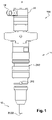
Figure 1 is a side feed injector to be tested on a test machine offigure 2 . -
Figure 2 is an 3D view from the test machine as per the invention. -
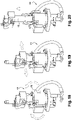
Figures 3 and 4 are sketches representing an operator using the machine offigure 1 . -
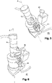
Figure 5 shows the injector offigure 1 arranged in the machine offigure 2 in a mounting position such as sketch infigure 3 . -
Figure 6 shows the injector offigure 1 arranged in the machine offigure 2 in a test position such as sketch infigure 4 . -
Figures 7 and 8 detail the test feature of the machine offigure 2 . -
Figure 9 shows a base member of the test feature. -
Figure 10, 11 and 12 detail an interface member also part of the test feature. -
Figure 13 is an exploded view of a head cap part of the test feature. -
Figure 14 is a 3D view of the injector fixed in the test feature. -
Figures 15, 16 and 17 detail the sequence of operations for mounting the injector onto the mounting feature. -
Figures 18, 19 and 20 detail the sequence of operations for disassemble the injector from the mounting feature. - In reference to
figure 1 is briefly presented adiesel fuel injector 10 adapted to be part of a fuel injection equipment of an internal combustion engine. Theinjector 10 has an elongated shape extending along a longitudinal axis X and it comprise aninjection nozzle 12 over which, by means of an injector capnut, anactuator assembly 14 is fixed. - In use, the
injector 10 is placed in a well provided on the engine cylinder head, the bottom end of the well opening into a compression chamber. Thehead end 16 of the injector, where is arranged anelectric connector 18 internally connected to an electrovalve, protrudes outside the well and, at the opposite end thetip 20 of the injection nozzle protrudes through said bottom opening for spraying pressurised fuel into said compression chamber. - The
fuel injector 10 shown onfigure 1 is aside feed injector 10S having an engine oil gallery 24O and adiesel fuel inlet 24S sealingly separated by O-rings? The gallery 24O forms an annular groove around the injector and, thefuel inlet 24S opens laterally on the outer face of the injector. In a fuel injection equipment provided with suchside feed injectors 10S, engine oil flows toward the injector in the gallery 24O and, diesel fuel enters the injector via saidinlet 24S. - Another embodiment of
injector 10 is atop feed injector 10T (shown onfigure 13 ) having afuel inlet 24T arranged atop the injector head. - During life of the
injector 10 service may be needed requiring tests and, diagnosis is made in atest machine 30 as generally presented infigure 2 . Typical tests performed are performance tests involving for instance a measure of current needed to spray high pressure fuel or, a measure of a fuel quantity sprayed in a certain time duration. - The
test machine 30 is designed to test several types ofinjectors 10 all having a similar configuration, as described above, but differing from one another by their actual dimensions, length, diameters... - Said
machine 30, designed to be placed on a table, has a substantially parallelepiped body with sixlateral walls 32 enclosing atest chamber 34 wherein is a fixed frame to which is attached atest feature 44 adapted to receive afuel injector 10. On the figure the most visible vertical wall is the "front wall" 32F which in the lower part defines an forwardly advanced portion where control knobs are arranged oriented toward an operator. Thisfront wall 32F is also provided with a rectangular access opening 36 enabling to enter and install the injector in thetest chamber 34, said opening being closed by adoor 38 laterally rotatable about a vertical axis. Above saidopening 36, on the upper part of thefront wall 32F, are arranged a "touch-screen"digital display 40 and anemergency stop button 42. Acommand unit 43 controls the machine as per inputs on saiddigital display 40. Said front wall arrangement is an example and is presented without intent to limit the application. In alternative embodiments, the knobs and the command display can be differently arranged otherwise on the wall or can be placed on a separate console connected to the machine. - As sketched on
figures 3 and 4 , an operator can easily arrange aninjector 10 in thetest chamber 34 by engaging it through theopening 36 and then after closing thedoor 38, he/she selects on thedisplay 40 the test to be executed. - In the
test chamber 34, theinjector 10 is arranged on saidtest feature 44 that can be moved between a mounting position PM (figures 3 and5 ) and, a test position PT (figures 4 and6 ). On the example presented, to move between said positions PM, PT the test feature is angularly tilted about an horizontal axis. Alternatively, other arrangements can be made for instance having said test feature translated toward the access opening 36 for easing the injector arrangement. - In the test position PT the injector is fixed in said
test feature 44 so the injector longitudinal axis X is parallel to thefront wall 32F and, alock 45 locks thetest feature 44 to the frame, the test feature not being able to move during the performance of a test. - The
lock 45 comprises a male member integral to thetest feature 44 and complementary engage-able in an adjusted female member integral to the frame and, a locking bolt that can be inserted in a bore drilled for part in the male member and for a other part in the body of the female member. In test position PT, the two parts of the bore are aligned and the locking bolt is engaged therein. Alternatively, many other locking mechanism can be provided. - In the mounting position PM the test feature is unlocked and is angularly pivoted toward the access opening 36 so the injector placed in the
test feature 44 has its longitudinal axis X extending through, or at least in the direction of, saidaccess opening 36. Consequently, setting the injector in thefeature 44 is made easy. - More particularly in reference to
figures 7 and 8 , saidtest feature 44 comprises abase member 46 and aninterface member 48. Thebase member 46 is fixed to the frame at it defines abottom side 46B wherein is hydraulically connected a highpressure fuel pipe 50 and, atop side 46T adapted to receive saidinterface member 48. Thebase member 46 is further provided with channels 51 enabling HP fuel to flow out of thepipe 50 into said channels 51, here after described, arranged in thesleeve 48. - The
interface member 48 of the present example is asleeve 48 having a tubular body with anupper end 48U and alower end 48L for complementary arrangement on thebase member 46. Saidsleeve 48 defines an axial throughbore 52 surrounded by a thickperipheral wall 54 in whichretention notches 56 are provided at thelower end 48L of the outer face. Saidnotches 56 enable to rigidly fixe thesleeve 48 to thebase member 46 by means of two clampingplates 58 screwed in the basemember top side 46T and engaged in saidnotches 56. Alternatively an annular groove could be provided replacing said notches and forming a shoulder for the clamps abutment. Theinjector 10 is inserted in thebore 52 and it is fixed in position by means of two latch toggle clamps 60 themselves fixed on thesleeve 48. - In reference to the
figure 9 is presented thetop side 46 T of the base member defining arecess 62 for positioning thesleeve 48 and said twoclamps 58 diametrically opposed. In said recess 62 acentral hole 64 enables thenozzle tip 20 to extend through and, around saidcentral hole 64 protrude HP fuel connections. - The
sleeve 48, presented on 3Dfigure 10 shows the outer face of thewall 54 with the clamping notches 56 (only one being visible) and apositioning slot 66F for complementary engagement ofpins 66M extending from the base member on the outer border of therecess 62. Also, said outer face is provided withflats 68 for screwing said toggle clamps 60 on theupper end 48U of the sleeve. -
Figures 11 and 12 are axial sections of a sleeve specially designed for aside feed injector 10S, said sections being 90° apart from one another. In the thickness of thewall 54 are drilled the vertical channels 51, comprising anoil channel 510 for the engine oil and, twodiesel fuel channels 51D (feed and return). Said drillings upwardly extend from an opening in the underface 49 of the sleeve (visible onfigure 10 ) to annular gallery in fluid connection with, the oil gallery 24O of thediesel fuel inlet 24S. - For top feed injectors, the
sleeve 48, not shown in section, does not need said drillings 51. - The
machine 30 has aunique base member 46 attached to the machine and common to all different types ofinjectors sleeves 48, each being specifically made to a specific type ofinjector sleeve 48 is the interface member between astandard base member 46 and aparticular injector 10. - All the
sleeves 48 have the same characteristics of throughbore 52,notches 56 on the outer face of the wall andflats 68 for fixing toggle clamps 60. - In reference to
figure 13 , to maintain theinjector 10 in the sleeve 48 (atop feed injector 10T is shown onfigure 13 ) aU-shaped member 72 is complementary engaged in clamp grooves of theinjector head 16, each arm of saidU-shaped member 72 being provided with ahook 74. Also shown on said figure, aninlet block 75 is screwed atop saidinjector 10T to enable fuel inlet into thetop feed injector 10T. - The toggle clamps 60 have a handle and a resilient ring both articulated about a fixation member fixed to the
sleeve 48. For fixing theinjector 10 each resilient ring is engaged in one of thehooks 74 and, by downwardly pulling the handles, the resilient rings are stretched urging and fixing the injector in the sleeve as presented onfigure 14 . In the example said rings have an elongated rectangular shape although alternatives exist. - Thanks to this arrangement an operator can easily set an injector in the machine, this operation being done manually just by pulling the handles of the toggle clamps without any needs for tools. The forces generated by the toggle clamps 60, once stretched by the handles, are sufficient to maintain the injector in place and, a test using a fuel flow for instance at 300 bars can be performed. This assembly of an injector on the test machine is illustrated by the sequence represented on
figures 15-17 , the arrows indicating the direction of insertion of the injector in the sleeve, the direction for engaging the rectangular rings in the hooks and the direction of pulling the handles. The opposite operation of disassembling said injector is shown on thefigures 18-20 . - In the embodiment presented the
sleeve 48 is fixed to thebase member 46 and thebase member 46 is articulated about the main frame. In another embodiment not shown, thebase member 46 may be fixed relative to the frame and, thesleeve 48 may be provided with a device to enable tilting of the sleeve relative to the base member. - To run the machine, an operator arranges the injector in the machine then he/she selects the test to be performed on the
digital display 40. By selecting a particular test and a specific injector 10 a set of input signals is sent to thecommand unit 43 wherein in a memory all the test procedures are stored and all the different type of injectors that can be tested on said machine. - Setting an injector on the machine for performing a test involves running the following method 100 steps:
- 102) providing an
injector 10 to be tested; - 104) providing the
sleeve 48 adapted to the injector provided; - 106) tilting the
base member 46 to the mounting position PM; - 108) clamping said
sleeve 48 on the base member; - 110) inserting the injector chosen at step 102) into the sleeve;
- 112) rigidly fixing said injector by downwardly pulling the handles of the latch toggle clamps 60;
- 114) tilting the
base member 46 back to the test position PT; - 116) locking the
base member 46 into said test position PT; - 118) closing the
door 38 of the access opening 36; - 120) selecting on the
digital display 40 the type of injector to be tested; - 122) selecting on the
digital display 40 the test to be executed. - When the test is completed the
injector 10 is removed from themachine 30 in following the steps of the following method 140: - 142) accessing the
injector 10 that has been tested and tilting thebase member 46 to the mounting position PM; - 144) releasing the latch toggle clamps 60 by upwardly pulling the handles of said latch toggle clamps;
- 146) removing the
injector 30 from thesleeve 48. -
- X
- longitudinal axis
- PM
- mounting position
- PT
- test position
- 10
- fuel injector
- 10S
- side feed fuel injector
- 10T
- top feed fuel injector
- 12
- nozzle
- 14
- actuator assembly
- 16
- head end of the injector
- 18
- connector
- 20
- tip end of the nozzle
- 22
- injection holes
- 24O
- Engine oil gallery
- 24S
- side feed injector diesel fuel inlet
- 24T
- top feed injector diesel fuel inlet
- 30
- test machine
- 32
- walls
- 32F
- front wall
- 34
- test chamber
- 36
- access opening
- 38
- door
- 40
- display
- 42
- emergency stop button
- 43
- command unit
- 44
- test feature
- 45
- lock
- 46
- base member
- 46B
- bottom side of the base
- 46T
- top side of the base
- 48
- interface member - sleeve
- 48U
- upper end of the sleeve
- 48L
- lower end of the sleeve
- 49
- under face of the sleeve
- 50
- pipe
- 51
- channels
- 510
- oil channel
- 51D
- diesel fuel channels
- 52
- bore
- 54
- wall
- 56
- notches
- 58
- clamping plates
- 60
- latch toggle clamps
- 62
- recess
- 64
- central opening
- 66F
- positioning slot
- 66M
- positioning pin
- 68
- flat
- 72
- U-shape member
- 74
- hook
- 75
- inlet block
- 100
- method to perform a test
- 102
- providing step
- 104
- providing step
- 106
- tilting step
- 108
- clamping step
- 110
- inserting step
- 112
- fixing step
- 114
- locking step
- 116
- locking step
- 118
- closing step
- 120
- selecting step
- 122
- selecting step
- 140
- method to remove an injector after test completion
- 142
- accessing step
- 144
- releasing step
- 146
- removing step
Claims (16)
- Test machine (30) adapted to perform high pressure fuel injector tests on several types of fuel injector (10), any of said injectors (10, 10S, 10T) having an injector body extending along a longitudinal axis (X) from a head (16) to a spray nozzle tip (20), the head (16) being provided with an electric connector (18) for transmitting command signals to an actuator cooperating with a valve member controlling spray through holes provided in said tip,the test machine (30) defining a test chamber (34), wherein the injector (10) can be fixed on a test feature (44) by means of a manually operable clamps (60) and wherein said manually operable clamps (60) comprises latch toggle clamps (60),wherein said test feature (44) comprises a base member (46) on which is arranged an interface member (48), said base member (46) being attached to the machine and being common to all types of injectors and, the interface member (48) being specifically designed for a particular injector, to each type of injector corresponding a dedicated interface members (48) and,wherein said test feature (44) is adapted to move between a mounting position (PM) and a test position (PT), the mounting position (PM) being suitable for arranging the injector (10) on said test feature (44) and, the test position (PT) being suitable for performing testing on said injector.
- Test machine (30) as claimed in claim 1 wherein, each of the toggle clamps (60) comprise a handle articulated about a fixation member for stretching a resilient ring, said fixation member being fixed to the test feature (44).
- Test machine (30) as claimed in claim 2 wherein for fixing the injector (10) said resilient ring is engaged in a hook (74) arranged on the injector head (16).
- Test machine (30) as claimed in claim 1 wherein said interface member (48) is a sleeve provided with a through bore (52) adapted to receive the nozzle (12) of the injector wherein it is sealingly inserted, the head (16) of the injector protruding outside the sleeve (48).
- Test machine (30) as claimed in claim 4 wherein the sleeve (48) is further provided with drillings (51) for inter-connecting a high pressure fuel inlet to the injector fuel inlet (24).
- Test machine (30) as claimed in claim 1 wherein, in said test position (PT) the longitudinal axis (X) of the injector (10) is substantially parallel to an opening access (36) provided to enable an injector (10) to be entered and installed in said test chamber (34).
- Test machine (30) as claimed in claim 6 wherein in said mounting position (PM), the test feature (44) is tilted toward said opening access (36) to ease the injector arrangement on the test feature (44).
- Test machine (30) as claimed in claim 7 wherein in said mounting position (PM) the longitudinal axis (X) of the injector arranged in the interface member (48) is extends through said opening access (36).
- Test machine (30) as claimed in 4 or 5 taken in combination with any one of the claims 1, 6 to 8 wherein the base member (46) is moveable relative to the machine and, the sleeve (48) is fixed onto the base member (46).
- Test machine (30) as claimed in 4 or 5 taken in combination with any one of the claims 1,6 to 8 wherein the base member (46) is fixed relative to the machine and, the sleeve (48) is moveable relative to the base (46).
- Test machine (30) as claimed as in any one of the preceding claims further comprising an electronic command unit (43) in a memory of which the tests method executable by the machine are uploaded.
- Test machine (30) as claimed in claim 11 further comprising a display (40) connected to said command unit (43) for an operator to select a particular test.
- Test machine (30) as claimed in any one of the preceding claims taken in combination with claim 6 wherein the machine has a substantially parallelepiped body enclosing said test chamber (44), said body having a front wall (32F) provided with said access opening (36).
- Test machine (30) as claimed in the combination of claims 12 and 13 wherein said display (40) is arranged on the front wall (32F), above the access opening (36).
- Method (100) for arranging an injector (10) on a test machine (30) as claimed in of the combination of the claims 1, 2, 4 and 12 combined with any one of the other claims, said method comprising the steps of:(102) providing an injector (10) to be tested;(104) providing a sleeve (48) adapted to the injector of step (102);(106) tilting the base member (46) to the mounting position (PM);(108) clamping said sleeve (48) on the base member (46);(110) inserting the injector (10) chosen at step (102) into the sleeve;(112) rigidly fixing said injector by downwardly pulling the handles of the latch toggle clamps (60);(114) tilting the base member (46) back to the test position (PT);(116) locking the base member into said test position (PT);(118) closing the access opening (36) by means of a door (38);(120) selecting on the display (40) the type of injector to be tested;(122) selecting on the display (40) the test to be executed.
- Method (140) for removing an injector (10) from a test machine (30) after having performed a test selected at step (122) according to claim 15, said method (140) comprising the steps of:(142) accessing the injector (10) that has been tested and, unlocking and tilting the base member (46) to the mounting position (PM);(144) releasing the latch toggle clamps (60) by upwardly pulling the handles of said latch toggle clamps;(146) removing the injector (10) from the sleeve (48).
Applications Claiming Priority (2)
| Application Number | Priority Date | Filing Date | Title |
|---|---|---|---|
| GB1717027.5A GB2567637B (en) | 2017-10-17 | 2017-10-17 | Injector test machine |
| PCT/EP2018/078097 WO2019076824A1 (en) | 2017-10-17 | 2018-10-15 | Injector test machine |
Publications (3)
| Publication Number | Publication Date |
|---|---|
| EP3698038A1 EP3698038A1 (en) | 2020-08-26 |
| EP3698038B1 true EP3698038B1 (en) | 2022-05-04 |
| EP3698038B8 EP3698038B8 (en) | 2022-06-22 |
Family
ID=60419404
Family Applications (1)
| Application Number | Title | Priority Date | Filing Date |
|---|---|---|---|
| EP18789583.4A Active EP3698038B8 (en) | 2017-10-17 | 2018-10-15 | Injector test machine |
Country Status (5)
| Country | Link |
|---|---|
| US (1) | US11339757B2 (en) |
| EP (1) | EP3698038B8 (en) |
| CN (1) | CN111448389B (en) |
| GB (1) | GB2567637B (en) |
| WO (1) | WO2019076824A1 (en) |
Families Citing this family (8)
| Publication number | Priority date | Publication date | Assignee | Title |
|---|---|---|---|---|
| GB2572012A (en) * | 2018-03-16 | 2019-09-18 | Delphi Tech Ip Ltd | Handling tool |
| GB2575779B (en) * | 2018-07-13 | 2021-07-07 | Delphi Tech Ip Ltd | Testing apparatus |
| GB2584716B (en) * | 2019-06-13 | 2022-03-02 | Delphi Tech Ip Ltd | Injector diagnostic tools |
| WO2022051563A1 (en) * | 2020-09-03 | 2022-03-10 | Arseneau Paul | Fuel injector testing machine |
| CN112177827A (en) * | 2020-11-06 | 2021-01-05 | 中船动力研究院有限公司 | Oil sprayer fixing device and test system |
| KR102467663B1 (en) * | 2022-05-30 | 2022-11-23 | 대한민국 | Hydraulic electric unit injector and electornic unit injector combined test controller apparatu for naval ship |
| US11885710B2 (en) * | 2022-06-08 | 2024-01-30 | Pratt & Whitney Canada Corp. | Oil nozzle health detection using liquid flow test |
| DE102024209730A1 (en) * | 2024-10-04 | 2026-04-09 | Robert Bosch Gesellschaft mit beschränkter Haftung | Method and device for removing and testing an injector |
Family Cites Families (17)
| Publication number | Priority date | Publication date | Assignee | Title |
|---|---|---|---|---|
| US3117444A (en) * | 1960-04-27 | 1964-01-14 | Hartridge Ltd Leslie | Injection nozzle tester |
| GB8512824D0 (en) * | 1985-05-21 | 1985-06-26 | Rentafitter Ltd | Cleaning system |
| US4808005A (en) | 1986-06-19 | 1989-02-28 | Cabot Corporation | Regulation of the flow-rate of carbon black into a pelletizer |
| US5317911A (en) * | 1992-03-16 | 1994-06-07 | Yaraschefski Steven M | Fixture for torquing components of an assembly |
| GB2328714A (en) * | 1997-08-27 | 1999-03-03 | Factor 1 Ltd | Automotive diagnostic apparatus allowing manual control of electronically controlled fuel injectors |
| DE10232301B4 (en) | 2002-07-16 | 2012-01-26 | Robert Bosch Gmbh | Inspection device for components of injection systems |
| CN201212437Y (en) * | 2008-07-01 | 2009-03-25 | 华南理工大学 | Test bench for electronically controlled fuel injector based on configuration software and PLC |
| DE102010029493A1 (en) * | 2010-05-31 | 2011-12-01 | Robert Bosch Gmbh | Device for testing fuel injectors and corresponding method |
| DE102010038760A1 (en) | 2010-08-02 | 2012-02-02 | Hochschule Reutlingen | Holding device for fuel injector |
| DE102011075485A1 (en) * | 2010-11-03 | 2012-05-03 | Hochschule Reutlingen | Variable injector holder |
| KR101255932B1 (en) * | 2011-10-24 | 2013-04-23 | 주식회사 현대케피코 | Test apparatus for endurance performance of fuel injection valve |
| CN202325962U (en) * | 2011-11-23 | 2012-07-11 | 湛江德利化油器有限公司 | Flow-characteristic test bench of fuel injector of motorcycle |
| DE102015218102A1 (en) | 2015-09-21 | 2017-03-23 | Robert Bosch Gmbh | injector |
| DE102015218090A1 (en) * | 2015-09-21 | 2017-03-23 | Robert Bosch Gmbh | injector |
| CN106194538A (en) * | 2016-08-17 | 2016-12-07 | 江苏大学 | A kind of back pressure that can regulate realizes the assay device of fuel injector Visualization |
| CN107035593A (en) * | 2017-05-04 | 2017-08-11 | 中国北方发动机研究所(天津) | The method of testing and device of a kind of fuel injector injection pressure |
| CN107061095B (en) * | 2017-06-01 | 2019-05-21 | 哈尔滨工程大学 | A kind of combined type fuel injector fuel injection characteristic measuring device and measuring method |
-
2017
- 2017-10-17 GB GB1717027.5A patent/GB2567637B/en active Active
-
2018
- 2018-10-15 EP EP18789583.4A patent/EP3698038B8/en active Active
- 2018-10-15 US US16/757,187 patent/US11339757B2/en active Active
- 2018-10-15 WO PCT/EP2018/078097 patent/WO2019076824A1/en not_active Ceased
- 2018-10-15 CN CN201880079234.6A patent/CN111448389B/en active Active
Also Published As
| Publication number | Publication date |
|---|---|
| GB201717027D0 (en) | 2017-11-29 |
| US11339757B2 (en) | 2022-05-24 |
| GB2567637A (en) | 2019-04-24 |
| CN111448389A (en) | 2020-07-24 |
| US20200340439A1 (en) | 2020-10-29 |
| GB2567637B (en) | 2020-05-27 |
| EP3698038A1 (en) | 2020-08-26 |
| WO2019076824A1 (en) | 2019-04-25 |
| CN111448389B (en) | 2022-05-03 |
| EP3698038B8 (en) | 2022-06-22 |
Similar Documents
| Publication | Publication Date | Title |
|---|---|---|
| EP3698038B1 (en) | Injector test machine | |
| US6318341B1 (en) | Fuel injection system | |
| KR101859430B1 (en) | Fuel injector assembly | |
| EP1815120B1 (en) | Method and device for leak testing a fuel injecting valve for an internal combustion engine | |
| DE102006042597A1 (en) | Insulation system for high pressure fuel injection components with direct injection and spark ignition | |
| US7431004B2 (en) | Method and device for operation of the glow plugs of a diesel engine | |
| KR102496837B1 (en) | maintenance system | |
| DE102010016419A1 (en) | Fuel injection valve | |
| DE102012014097A1 (en) | A method of mounting a fuel rail assembly for a direct injection engine and apparatus therefor | |
| EP3821120B1 (en) | Testing apparatus | |
| KR101760409B1 (en) | apparatus for testing capability of pressure control valve | |
| KR101478631B1 (en) | Methode for Pre-Insfecting Injector | |
| DE102011075870A1 (en) | Method for assessing the operability of a fuel injection system of an internal combustion engine | |
| DE102010040541A1 (en) | Fuel storage block for testing high pressure components of fuel injectors | |
| DE102013002758B4 (en) | Flushing procedure for use with a fuel injector | |
| DE102006061894A1 (en) | Fuel injection system's e.g. fuel injector, malfunctioning diagnosing device for motor vehicle, has controlling and evaluating unit to diagnose malfunctioning of system from sensor signal by considering diagnostic operating condition | |
| CN109142106B (en) | Engine cylinder head test device | |
| DE19925099A1 (en) | Operating method for automobile engine fuel system provides fault diagnosis by evaluating difference between pressure signals corresponding to alternate selected fuel pressure values | |
| US12030162B2 (en) | Handling tool | |
| CN109253009B (en) | Guided internal combustion engine fuel injector cleaning detection system and method | |
| DE10206908B4 (en) | Injector with improved connection geometry | |
| EP2765302B1 (en) | Apparatus, in particular a pump apparatus for a large diesel engine, and method of cleaning an apparatus | |
| DE10309233A1 (en) | Fluid system for an internal combustion engine | |
| JPS595870A (en) | Unit type fuel injection pump device | |
| DE102015003012B4 (en) | Method and control device for functional testing of ignition fluid injectors |
Legal Events
| Date | Code | Title | Description |
|---|---|---|---|
| STAA | Information on the status of an ep patent application or granted ep patent |
Free format text: STATUS: UNKNOWN |
|
| STAA | Information on the status of an ep patent application or granted ep patent |
Free format text: STATUS: THE INTERNATIONAL PUBLICATION HAS BEEN MADE |
|
| PUAI | Public reference made under article 153(3) epc to a published international application that has entered the european phase |
Free format text: ORIGINAL CODE: 0009012 |
|
| STAA | Information on the status of an ep patent application or granted ep patent |
Free format text: STATUS: REQUEST FOR EXAMINATION WAS MADE |
|
| 17P | Request for examination filed |
Effective date: 20200518 |
|
| AK | Designated contracting states |
Kind code of ref document: A1 Designated state(s): AL AT BE BG CH CY CZ DE DK EE ES FI FR GB GR HR HU IE IS IT LI LT LU LV MC MK MT NL NO PL PT RO RS SE SI SK SM TR |
|
| AX | Request for extension of the european patent |
Extension state: BA ME |
|
| DAV | Request for validation of the european patent (deleted) | ||
| DAX | Request for extension of the european patent (deleted) | ||
| STAA | Information on the status of an ep patent application or granted ep patent |
Free format text: STATUS: EXAMINATION IS IN PROGRESS |
|
| 17Q | First examination report despatched |
Effective date: 20210331 |
|
| GRAP | Despatch of communication of intention to grant a patent |
Free format text: ORIGINAL CODE: EPIDOSNIGR1 |
|
| STAA | Information on the status of an ep patent application or granted ep patent |
Free format text: STATUS: GRANT OF PATENT IS INTENDED |
|
| INTG | Intention to grant announced |
Effective date: 20211202 |
|
| GRAS | Grant fee paid |
Free format text: ORIGINAL CODE: EPIDOSNIGR3 |
|
| GRAA | (expected) grant |
Free format text: ORIGINAL CODE: 0009210 |
|
| STAA | Information on the status of an ep patent application or granted ep patent |
Free format text: STATUS: THE PATENT HAS BEEN GRANTED |
|
| AK | Designated contracting states |
Kind code of ref document: B1 Designated state(s): AL AT BE BG CH CY CZ DE DK EE ES FI FR GB GR HR HU IE IS IT LI LT LU LV MC MK MT NL NO PL PT RO RS SE SI SK SM TR |
|
| REG | Reference to a national code |
Ref country code: GB Ref legal event code: FG4D |
|
| REG | Reference to a national code |
Ref country code: CH Ref legal event code: EP |
|
| REG | Reference to a national code |
Ref country code: AT Ref legal event code: REF Ref document number: 1489283 Country of ref document: AT Kind code of ref document: T Effective date: 20220515 |
|
| RAP4 | Party data changed (patent owner data changed or rights of a patent transferred) |
Owner name: DELPHI TECHNOLOGIES IP LIMITED |
|
| REG | Reference to a national code |
Ref country code: DE Ref legal event code: R096 Ref document number: 602018035065 Country of ref document: DE |
|
| REG | Reference to a national code |
Ref country code: IE Ref legal event code: FG4D |
|
| REG | Reference to a national code |
Ref country code: CH Ref legal event code: PK Free format text: BERICHTIGUNG B8 |
|
| REG | Reference to a national code |
Ref country code: DE Ref legal event code: R081 Ref document number: 602018035065 Country of ref document: DE Owner name: PHINIA DELPHI LUXEMBOURG SARL, LU Free format text: FORMER OWNER: DELPHI TECHNOLOGIES IP LIMITED, SAINT MICHAEL, BB |
|
| REG | Reference to a national code |
Ref country code: LT Ref legal event code: MG9D |
|
| REG | Reference to a national code |
Ref country code: NL Ref legal event code: MP Effective date: 20220504 |
|
| REG | Reference to a national code |
Ref country code: AT Ref legal event code: MK05 Ref document number: 1489283 Country of ref document: AT Kind code of ref document: T Effective date: 20220504 |
|
| PG25 | Lapsed in a contracting state [announced via postgrant information from national office to epo] |
Ref country code: SE Free format text: LAPSE BECAUSE OF FAILURE TO SUBMIT A TRANSLATION OF THE DESCRIPTION OR TO PAY THE FEE WITHIN THE PRESCRIBED TIME-LIMIT Effective date: 20220504 Ref country code: PT Free format text: LAPSE BECAUSE OF FAILURE TO SUBMIT A TRANSLATION OF THE DESCRIPTION OR TO PAY THE FEE WITHIN THE PRESCRIBED TIME-LIMIT Effective date: 20220905 Ref country code: NO Free format text: LAPSE BECAUSE OF FAILURE TO SUBMIT A TRANSLATION OF THE DESCRIPTION OR TO PAY THE FEE WITHIN THE PRESCRIBED TIME-LIMIT Effective date: 20220804 Ref country code: NL Free format text: LAPSE BECAUSE OF FAILURE TO SUBMIT A TRANSLATION OF THE DESCRIPTION OR TO PAY THE FEE WITHIN THE PRESCRIBED TIME-LIMIT Effective date: 20220504 Ref country code: LT Free format text: LAPSE BECAUSE OF FAILURE TO SUBMIT A TRANSLATION OF THE DESCRIPTION OR TO PAY THE FEE WITHIN THE PRESCRIBED TIME-LIMIT Effective date: 20220504 Ref country code: HR Free format text: LAPSE BECAUSE OF FAILURE TO SUBMIT A TRANSLATION OF THE DESCRIPTION OR TO PAY THE FEE WITHIN THE PRESCRIBED TIME-LIMIT Effective date: 20220504 Ref country code: GR Free format text: LAPSE BECAUSE OF FAILURE TO SUBMIT A TRANSLATION OF THE DESCRIPTION OR TO PAY THE FEE WITHIN THE PRESCRIBED TIME-LIMIT Effective date: 20220805 Ref country code: FI Free format text: LAPSE BECAUSE OF FAILURE TO SUBMIT A TRANSLATION OF THE DESCRIPTION OR TO PAY THE FEE WITHIN THE PRESCRIBED TIME-LIMIT Effective date: 20220504 Ref country code: ES Free format text: LAPSE BECAUSE OF FAILURE TO SUBMIT A TRANSLATION OF THE DESCRIPTION OR TO PAY THE FEE WITHIN THE PRESCRIBED TIME-LIMIT Effective date: 20220504 Ref country code: BG Free format text: LAPSE BECAUSE OF FAILURE TO SUBMIT A TRANSLATION OF THE DESCRIPTION OR TO PAY THE FEE WITHIN THE PRESCRIBED TIME-LIMIT Effective date: 20220804 Ref country code: AT Free format text: LAPSE BECAUSE OF FAILURE TO SUBMIT A TRANSLATION OF THE DESCRIPTION OR TO PAY THE FEE WITHIN THE PRESCRIBED TIME-LIMIT Effective date: 20220504 |
|
| PG25 | Lapsed in a contracting state [announced via postgrant information from national office to epo] |
Ref country code: RS Free format text: LAPSE BECAUSE OF FAILURE TO SUBMIT A TRANSLATION OF THE DESCRIPTION OR TO PAY THE FEE WITHIN THE PRESCRIBED TIME-LIMIT Effective date: 20220504 Ref country code: PL Free format text: LAPSE BECAUSE OF FAILURE TO SUBMIT A TRANSLATION OF THE DESCRIPTION OR TO PAY THE FEE WITHIN THE PRESCRIBED TIME-LIMIT Effective date: 20220504 Ref country code: LV Free format text: LAPSE BECAUSE OF FAILURE TO SUBMIT A TRANSLATION OF THE DESCRIPTION OR TO PAY THE FEE WITHIN THE PRESCRIBED TIME-LIMIT Effective date: 20220504 Ref country code: IS Free format text: LAPSE BECAUSE OF FAILURE TO SUBMIT A TRANSLATION OF THE DESCRIPTION OR TO PAY THE FEE WITHIN THE PRESCRIBED TIME-LIMIT Effective date: 20220904 |
|
| PG25 | Lapsed in a contracting state [announced via postgrant information from national office to epo] |
Ref country code: SM Free format text: LAPSE BECAUSE OF FAILURE TO SUBMIT A TRANSLATION OF THE DESCRIPTION OR TO PAY THE FEE WITHIN THE PRESCRIBED TIME-LIMIT Effective date: 20220504 Ref country code: SK Free format text: LAPSE BECAUSE OF FAILURE TO SUBMIT A TRANSLATION OF THE DESCRIPTION OR TO PAY THE FEE WITHIN THE PRESCRIBED TIME-LIMIT Effective date: 20220504 Ref country code: RO Free format text: LAPSE BECAUSE OF FAILURE TO SUBMIT A TRANSLATION OF THE DESCRIPTION OR TO PAY THE FEE WITHIN THE PRESCRIBED TIME-LIMIT Effective date: 20220504 Ref country code: EE Free format text: LAPSE BECAUSE OF FAILURE TO SUBMIT A TRANSLATION OF THE DESCRIPTION OR TO PAY THE FEE WITHIN THE PRESCRIBED TIME-LIMIT Effective date: 20220504 Ref country code: DK Free format text: LAPSE BECAUSE OF FAILURE TO SUBMIT A TRANSLATION OF THE DESCRIPTION OR TO PAY THE FEE WITHIN THE PRESCRIBED TIME-LIMIT Effective date: 20220504 Ref country code: CZ Free format text: LAPSE BECAUSE OF FAILURE TO SUBMIT A TRANSLATION OF THE DESCRIPTION OR TO PAY THE FEE WITHIN THE PRESCRIBED TIME-LIMIT Effective date: 20220504 |
|
| REG | Reference to a national code |
Ref country code: DE Ref legal event code: R097 Ref document number: 602018035065 Country of ref document: DE |
|
| PLBE | No opposition filed within time limit |
Free format text: ORIGINAL CODE: 0009261 |
|
| STAA | Information on the status of an ep patent application or granted ep patent |
Free format text: STATUS: NO OPPOSITION FILED WITHIN TIME LIMIT |
|
| PG25 | Lapsed in a contracting state [announced via postgrant information from national office to epo] |
Ref country code: AL Free format text: LAPSE BECAUSE OF FAILURE TO SUBMIT A TRANSLATION OF THE DESCRIPTION OR TO PAY THE FEE WITHIN THE PRESCRIBED TIME-LIMIT Effective date: 20220504 |
|
| 26N | No opposition filed |
Effective date: 20230207 |
|
| PG25 | Lapsed in a contracting state [announced via postgrant information from national office to epo] |
Ref country code: SI Free format text: LAPSE BECAUSE OF FAILURE TO SUBMIT A TRANSLATION OF THE DESCRIPTION OR TO PAY THE FEE WITHIN THE PRESCRIBED TIME-LIMIT Effective date: 20220504 Ref country code: MC Free format text: LAPSE BECAUSE OF FAILURE TO SUBMIT A TRANSLATION OF THE DESCRIPTION OR TO PAY THE FEE WITHIN THE PRESCRIBED TIME-LIMIT Effective date: 20220504 |
|
| REG | Reference to a national code |
Ref country code: CH Ref legal event code: PL |
|
| P01 | Opt-out of the competence of the unified patent court (upc) registered |
Effective date: 20230327 |
|
| REG | Reference to a national code |
Ref country code: BE Ref legal event code: MM Effective date: 20221031 |
|
| PG25 | Lapsed in a contracting state [announced via postgrant information from national office to epo] |
Ref country code: LU Free format text: LAPSE BECAUSE OF NON-PAYMENT OF DUE FEES Effective date: 20221015 |
|
| PG25 | Lapsed in a contracting state [announced via postgrant information from national office to epo] |
Ref country code: LI Free format text: LAPSE BECAUSE OF NON-PAYMENT OF DUE FEES Effective date: 20221031 Ref country code: CH Free format text: LAPSE BECAUSE OF NON-PAYMENT OF DUE FEES Effective date: 20221031 |
|
| PG25 | Lapsed in a contracting state [announced via postgrant information from national office to epo] |
Ref country code: BE Free format text: LAPSE BECAUSE OF NON-PAYMENT OF DUE FEES Effective date: 20221031 |
|
| PG25 | Lapsed in a contracting state [announced via postgrant information from national office to epo] |
Ref country code: IE Free format text: LAPSE BECAUSE OF NON-PAYMENT OF DUE FEES Effective date: 20221015 |
|
| PG25 | Lapsed in a contracting state [announced via postgrant information from national office to epo] |
Ref country code: IT Free format text: LAPSE BECAUSE OF FAILURE TO SUBMIT A TRANSLATION OF THE DESCRIPTION OR TO PAY THE FEE WITHIN THE PRESCRIBED TIME-LIMIT Effective date: 20220504 |
|
| REG | Reference to a national code |
Ref country code: DE Ref legal event code: R081 Ref document number: 602018035065 Country of ref document: DE Owner name: PHINIA DELPHI LUXEMBOURG SARL, LU Free format text: FORMER OWNER: DELPHI TECHNOLOGIES IP LIMITED, ST. MICHAEL, BB |
|
| PG25 | Lapsed in a contracting state [announced via postgrant information from national office to epo] |
Ref country code: CY Free format text: LAPSE BECAUSE OF FAILURE TO SUBMIT A TRANSLATION OF THE DESCRIPTION OR TO PAY THE FEE WITHIN THE PRESCRIBED TIME-LIMIT Effective date: 20220504 |
|
| REG | Reference to a national code |
Ref country code: GB Ref legal event code: 732E Free format text: REGISTERED BETWEEN 20240411 AND 20240417 |
|
| PG25 | Lapsed in a contracting state [announced via postgrant information from national office to epo] |
Ref country code: MK Free format text: LAPSE BECAUSE OF FAILURE TO SUBMIT A TRANSLATION OF THE DESCRIPTION OR TO PAY THE FEE WITHIN THE PRESCRIBED TIME-LIMIT Effective date: 20220504 Ref country code: HU Free format text: LAPSE BECAUSE OF FAILURE TO SUBMIT A TRANSLATION OF THE DESCRIPTION OR TO PAY THE FEE WITHIN THE PRESCRIBED TIME-LIMIT; INVALID AB INITIO Effective date: 20181015 |
|
| PG25 | Lapsed in a contracting state [announced via postgrant information from national office to epo] |
Ref country code: TR Free format text: LAPSE BECAUSE OF FAILURE TO SUBMIT A TRANSLATION OF THE DESCRIPTION OR TO PAY THE FEE WITHIN THE PRESCRIBED TIME-LIMIT Effective date: 20220504 |
|
| PG25 | Lapsed in a contracting state [announced via postgrant information from national office to epo] |
Ref country code: MT Free format text: LAPSE BECAUSE OF FAILURE TO SUBMIT A TRANSLATION OF THE DESCRIPTION OR TO PAY THE FEE WITHIN THE PRESCRIBED TIME-LIMIT Effective date: 20220504 |
|
| PG25 | Lapsed in a contracting state [announced via postgrant information from national office to epo] |
Ref country code: BG Free format text: LAPSE BECAUSE OF FAILURE TO SUBMIT A TRANSLATION OF THE DESCRIPTION OR TO PAY THE FEE WITHIN THE PRESCRIBED TIME-LIMIT Effective date: 20220504 |
|
| PG25 | Lapsed in a contracting state [announced via postgrant information from national office to epo] |
Ref country code: BG Free format text: LAPSE BECAUSE OF FAILURE TO SUBMIT A TRANSLATION OF THE DESCRIPTION OR TO PAY THE FEE WITHIN THE PRESCRIBED TIME-LIMIT Effective date: 20220504 |
|
| PGFP | Annual fee paid to national office [announced via postgrant information from national office to epo] |
Ref country code: GB Payment date: 20250911 Year of fee payment: 8 |
|
| PGFP | Annual fee paid to national office [announced via postgrant information from national office to epo] |
Ref country code: FR Payment date: 20250912 Year of fee payment: 8 |
|
| PGFP | Annual fee paid to national office [announced via postgrant information from national office to epo] |
Ref country code: DE Payment date: 20250912 Year of fee payment: 8 |