EP3698037B1 - Metering valve for a pump unit for feeding fuel to an internal combustion engine and pump unit comprising such a valve - Google Patents
Metering valve for a pump unit for feeding fuel to an internal combustion engine and pump unit comprising such a valve Download PDFInfo
- Publication number
- EP3698037B1 EP3698037B1 EP18783497.3A EP18783497A EP3698037B1 EP 3698037 B1 EP3698037 B1 EP 3698037B1 EP 18783497 A EP18783497 A EP 18783497A EP 3698037 B1 EP3698037 B1 EP 3698037B1
- Authority
- EP
- European Patent Office
- Prior art keywords
- valve
- fuel
- sleeve
- plug
- piston
- Prior art date
- Legal status (The legal status is an assumption and is not a legal conclusion. Google has not performed a legal analysis and makes no representation as to the accuracy of the status listed.)
- Active
Links
Images

Classifications
-
- F—MECHANICAL ENGINEERING; LIGHTING; HEATING; WEAPONS; BLASTING
- F02—COMBUSTION ENGINES; HOT-GAS OR COMBUSTION-PRODUCT ENGINE PLANTS
- F02M—SUPPLYING COMBUSTION ENGINES IN GENERAL WITH COMBUSTIBLE MIXTURES OR CONSTITUENTS THEREOF
- F02M59/00—Pumps specially adapted for fuel-injection and not provided for in groups F02M39/00 -F02M57/00, e.g. rotary cylinder-block type of pumps
- F02M59/20—Varying fuel delivery in quantity or timing
- F02M59/34—Varying fuel delivery in quantity or timing by throttling of passages to pumping elements or of overflow passages, e.g. throttling by means of a pressure-controlled sliding valve having liquid stop or abutment
-
- F—MECHANICAL ENGINEERING; LIGHTING; HEATING; WEAPONS; BLASTING
- F02—COMBUSTION ENGINES; HOT-GAS OR COMBUSTION-PRODUCT ENGINE PLANTS
- F02M—SUPPLYING COMBUSTION ENGINES IN GENERAL WITH COMBUSTIBLE MIXTURES OR CONSTITUENTS THEREOF
- F02M59/00—Pumps specially adapted for fuel-injection and not provided for in groups F02M39/00 -F02M57/00, e.g. rotary cylinder-block type of pumps
- F02M59/44—Details, components parts, or accessories not provided for in, or of interest apart from, the apparatus of groups F02M59/02 - F02M59/42; Pumps having transducers, e.g. to measure displacement of pump rack or piston
- F02M59/46—Valves
- F02M59/466—Electrically operated valves, e.g. using electromagnetic or piezoelectric operating means
-
- F—MECHANICAL ENGINEERING; LIGHTING; HEATING; WEAPONS; BLASTING
- F02—COMBUSTION ENGINES; HOT-GAS OR COMBUSTION-PRODUCT ENGINE PLANTS
- F02M—SUPPLYING COMBUSTION ENGINES IN GENERAL WITH COMBUSTIBLE MIXTURES OR CONSTITUENTS THEREOF
- F02M63/00—Other fuel-injection apparatus having pertinent characteristics not provided for in groups F02M39/00 - F02M57/00 or F02M67/00; Details, component parts, or accessories of fuel-injection apparatus, not provided for in, or of interest apart from, the apparatus of groups F02M39/00 - F02M61/00 or F02M67/00; Combination of fuel pump with other devices, e.g. lubricating oil pump
- F02M63/0012—Valves
- F02M63/0014—Valves characterised by the valve actuating means
- F02M63/0015—Valves characterised by the valve actuating means electrical, e.g. using solenoid
- F02M63/0017—Valves characterised by the valve actuating means electrical, e.g. using solenoid using electromagnetic operating means
-
- F—MECHANICAL ENGINEERING; LIGHTING; HEATING; WEAPONS; BLASTING
- F02—COMBUSTION ENGINES; HOT-GAS OR COMBUSTION-PRODUCT ENGINE PLANTS
- F02M—SUPPLYING COMBUSTION ENGINES IN GENERAL WITH COMBUSTIBLE MIXTURES OR CONSTITUENTS THEREOF
- F02M63/00—Other fuel-injection apparatus having pertinent characteristics not provided for in groups F02M39/00 - F02M57/00 or F02M67/00; Details, component parts, or accessories of fuel-injection apparatus, not provided for in, or of interest apart from, the apparatus of groups F02M39/00 - F02M61/00 or F02M67/00; Combination of fuel pump with other devices, e.g. lubricating oil pump
- F02M63/0012—Valves
- F02M63/0031—Valves characterized by the type of valves, e.g. special valve member details, valve seat details, valve housing details
- F02M63/004—Sliding valves, e.g. spool valves, i.e. whereby the closing member has a sliding movement along a seat for opening and closing
-
- F—MECHANICAL ENGINEERING; LIGHTING; HEATING; WEAPONS; BLASTING
- F02—COMBUSTION ENGINES; HOT-GAS OR COMBUSTION-PRODUCT ENGINE PLANTS
- F02M—SUPPLYING COMBUSTION ENGINES IN GENERAL WITH COMBUSTIBLE MIXTURES OR CONSTITUENTS THEREOF
- F02M63/00—Other fuel-injection apparatus having pertinent characteristics not provided for in groups F02M39/00 - F02M57/00 or F02M67/00; Details, component parts, or accessories of fuel-injection apparatus, not provided for in, or of interest apart from, the apparatus of groups F02M39/00 - F02M61/00 or F02M67/00; Combination of fuel pump with other devices, e.g. lubricating oil pump
- F02M63/0012—Valves
- F02M63/0031—Valves characterized by the type of valves, e.g. special valve member details, valve seat details, valve housing details
- F02M63/0056—Throttling valves, e.g. having variable opening positions throttling the flow
-
- F—MECHANICAL ENGINEERING; LIGHTING; HEATING; WEAPONS; BLASTING
- F02—COMBUSTION ENGINES; HOT-GAS OR COMBUSTION-PRODUCT ENGINE PLANTS
- F02M—SUPPLYING COMBUSTION ENGINES IN GENERAL WITH COMBUSTIBLE MIXTURES OR CONSTITUENTS THEREOF
- F02M63/00—Other fuel-injection apparatus having pertinent characteristics not provided for in groups F02M39/00 - F02M57/00 or F02M67/00; Details, component parts, or accessories of fuel-injection apparatus, not provided for in, or of interest apart from, the apparatus of groups F02M39/00 - F02M61/00 or F02M67/00; Combination of fuel pump with other devices, e.g. lubricating oil pump
- F02M63/0012—Valves
- F02M63/007—Details not provided for in, or of interest apart from, the apparatus of the groups F02M63/0014 - F02M63/0059
- F02M63/0075—Stop members in valves, e.g. plates or disks limiting the movement of armature, valve or spring
-
- F—MECHANICAL ENGINEERING; LIGHTING; HEATING; WEAPONS; BLASTING
- F02—COMBUSTION ENGINES; HOT-GAS OR COMBUSTION-PRODUCT ENGINE PLANTS
- F02M—SUPPLYING COMBUSTION ENGINES IN GENERAL WITH COMBUSTIBLE MIXTURES OR CONSTITUENTS THEREOF
- F02M63/00—Other fuel-injection apparatus having pertinent characteristics not provided for in groups F02M39/00 - F02M57/00 or F02M67/00; Details, component parts, or accessories of fuel-injection apparatus, not provided for in, or of interest apart from, the apparatus of groups F02M39/00 - F02M61/00 or F02M67/00; Combination of fuel pump with other devices, e.g. lubricating oil pump
- F02M63/0012—Valves
- F02M63/007—Details not provided for in, or of interest apart from, the apparatus of the groups F02M63/0014 - F02M63/0059
- F02M63/0078—Valve member details, e.g. special shape, hollow or fuel passages in the valve member
-
- F—MECHANICAL ENGINEERING; LIGHTING; HEATING; WEAPONS; BLASTING
- F02—COMBUSTION ENGINES; HOT-GAS OR COMBUSTION-PRODUCT ENGINE PLANTS
- F02M—SUPPLYING COMBUSTION ENGINES IN GENERAL WITH COMBUSTIBLE MIXTURES OR CONSTITUENTS THEREOF
- F02M63/00—Other fuel-injection apparatus having pertinent characteristics not provided for in groups F02M39/00 - F02M57/00 or F02M67/00; Details, component parts, or accessories of fuel-injection apparatus, not provided for in, or of interest apart from, the apparatus of groups F02M39/00 - F02M61/00 or F02M67/00; Combination of fuel pump with other devices, e.g. lubricating oil pump
- F02M63/0012—Valves
- F02M63/007—Details not provided for in, or of interest apart from, the apparatus of the groups F02M63/0014 - F02M63/0059
- F02M63/0078—Valve member details, e.g. special shape, hollow or fuel passages in the valve member
- F02M63/008—Hollow valve members, e.g. members internally guided
Definitions
- the present invention relates to a metering valve for a pump unit for feeding fuel, preferably diesel fuel, to an internal combustion engine.
- the present invention also relates to a pump unit for feeding fuel, preferably diesel fuel, to an internal combustion engine in which this pump unit comprises the aforementioned metering valve.
- a metering valve for a pump unit for feeding fuel from a tank to an internal combustion engine is known from document EP 1 674 717 A1 .
- This valve comprises a sleeve having an axis and provided with a first open end for receiving a thruster, a second opposite end provided with an opening for axially discharging the fuel and at least one side opening for feeding fuel.
- a plugshaped piston is slidably housed along the axis inside the sleeve, the piston having a closed end with an outer surface in contact with the thruster and an open opposite end.
- a plug is housed inside the discharge opening of the sleeve.
- a spring is arranged between the plug and the inner surface of the closed end of the piston.
- the plug has several openings forming lateral flow channels for discharging the fuel.
- the piston is cooperating with a valve seat and upon movement of the thruster is selectively opening and closing the valve seat.
- fuel passes through the valve seat and through the openings of the plug and is discharged via the open end of the sleeve.
- the valve according to this document is a poppet valve opening and closing the valve seat. It is difficult to adjust a variable flow through the valve. Today there exists the need to increase the hourly flow of fuel passing through the valve and with the lateral flow channels the cross-section for the flow of fuel is restricted.
- an object of the present invention is to provide a metering valve able to increase the hourly flow of fuel passing inside these valves without increasing the design cost.
- a metering valve for a pump unit for feeding fuel from a tank to an internal-combustion engine comprises:
- the piston has at least one side opening cooperating with the side opening of the sleeve so that selectively fuel passes through the side opening of the sleeve and the side opening of the piston and is discharged via the open end of the piston and the plug is provided with an axial through-hole centered on the axis of the sleeve.
- the overall aperture for discharging fuel from the metering valve is increased.
- the particular profile of the piston windows which are for example triangular in shape, ensures that the fuel flow passing during the movement of the piston with respect to the fixed sleeve is proportional.
- the plug is shaped so that, when it is housed inside the axial discharge opening of the sleeve, it forms a plurality of lateral flow channels for discharging fuel, these lateral flow channels being arranged in an axially symmetrical manner with respect to the axis A.
- the load of the spring is transmitted to the plug in a uniform manner around the axis A.
- the plug comprises an inner face provided with an axial step for seating the spring.
- the plug comprises a side wall having at least one portion for contact with the axial discharge opening of the sleeve and at least one inset portion having a radius R2 from the axis A smaller than the radius R1 of the contact portion.
- the radius R2 of the inset portion coincides with the outer radius of the axial step against which the spring rests.
- the invention has been described above with reference to a metering valve. However, the present invention is also applicable to the pump unit which comprises this valve.
- the internal combustion engine 3 is shown only in schematic form and comprising a common header 12 fed by the high-pressure delivery ducts 13 and a plurality of injectors 14 configured to atomize and inject the high-pressure fuel into the cylinders of the internal combustion engine 3 (not shown).
- the high-pressure pump 5 is shown only in schematic form and comprises two pumping pistons 8 housed inside associated cylinders 9 formed in a head 10 and fed with the low-pressure fuel at feed valves 11.
- the cylinders 9 are in turn connected to delivery valves 16 for feeding the high-pressure fuel to the engine 3.
- Figure 1 shows moreover in schematic form a cam shaft 15 which imparts the reciprocating movement inside the cylinders 9 to the pistons 8.
- the pump unit comprises a metering valve 7. The operating principle of this valve 7 will emerge more clearly from the description of Figure 2 .
- the metering unit 2 is an electric valve, with at least one inlet side which communicates with the delivery of the low-pressure pump and at least one outlet side which communicates with the intake duct for feeding the intake chamber.
- the metering unit 7 is flanged on a support body 17 which normally forms part of the high-pressure pump body and comprises an electromagnetic head 18.
- This electromagnetic head 18 comprises a coil 19 having an axis A inside which a core 20 made of magnetizable material is formed.
- the core 20 is mounted in an axially slidable manner along the axis A and comprises a thruster 21 coaxial with the axis A.
- the electromagnetic head 4 comprises furthermore a cup-shaped piece 22 which supports an electrical connector 23 for supplying current to the coil 19.
- This cup-shaped piece 22 houses a first end 25 of the thruster 21 and is provided with a flange 24 for connecting the valve 7 to the support body 17.
- the opposite end 26 of the thruster 21 penetrates inside a sleeve 27 which is coaxial with the axis A and is provided with a flange 28' which extends radially inwards, from the flange 24 of the cup-shaped piece 22, so that the sleeve 27 is locked by the cup-shaped piece 22 against the support body 17.
- the sleeve 27 penetrates at least partially inside the support 17. This portion of the sleeve 27 inside the support body 17 is provided with side openings 28 fed with the fuel delivered by the low-pressure pump 4. Special filters 29 are provided opposite these side openings 28.
- a piston 30 sliding along the axis A is housed inside the sleeve 27.
- This piston 30 is plug-shaped, namely comprises a cylindrical body with a closed end or top 31 and an open opposite end. The outer surface of the top 31 is pressed in a spring-loaded manner against the thruster 21.
- a spring 32 is housed, partly inside the piston having a first end making bearing contact against the inner surface of the piston 30 and a second end bearing against a retaining plug 33 fastened inside the axial discharge opening 35 of the sleeve 27 in a position facing the open end of the piston 30.
- the movable piston 30 comprises side windows 34 (only partially visible in Figure 2 ) which, during the piston stroke, are selectively arranged opposite the side openings 28 of the sleeve 27. In these conditions the fuel first passes beyond the openings 28 of the sleeve 27 and the windows 34 of the piston 30 and is then discharged via the open end of the piston 30.
- the particular profile of the windows 34 of the piston 30 is designed such that the fuel flow passing during the downward movement of the said piston 30 is proportional.
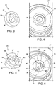
- Figures 3 and 4 and Figures 5 and 6 show respectively a retaining plug according to the prior art and according to the invention and the associated connections with the discharge opening 35 of the sleeve 27.
- the retaining plug 33 of the spring 32 has a cylindrical shape and comprises a side wall 36 so as to engage with the discharge opening 35 of the sleeve 17 and comprises in the surface facing the piston 30 a circumferential step 37 centred on the axis A for stably seating the spring 32.
- the retaining plug 33 comprises a through-hole 38 centred on the axis A and having a radius smaller than the step 37.
- Figures 5 and 6 show how, according to the present invention, it is possible to increase the flow passing via the discharge opening 35, without modifying this discharge opening 35 nor the dimensions of the through-hole 38.
- the side wall 36 is shaped so as to identify a portions 40 making contact with the discharge opening 35 and at least one side opening 39 between the side wall 36 and the discharge opening 35.
- This side opening 39 is in fact defined by an inset portion 41 having a radius R2 relative to the axis A smaller than the radius R1 of portion 40 making contact with the discharge opening 35.
- three side openings 39 are present, these being formed in the region of three inset portions 41, so as to ensure an axial symmetry able to absorb uniformly the load of the spring 32.
- the minimum radius of these inset portions 41, which forms the maximum opening 39, coincides with the outer radius of the step 37.
Landscapes
- Engineering & Computer Science (AREA)
- Chemical & Material Sciences (AREA)
- Combustion & Propulsion (AREA)
- Mechanical Engineering (AREA)
- General Engineering & Computer Science (AREA)
- Physics & Mathematics (AREA)
- Electromagnetism (AREA)
- Fuel-Injection Apparatus (AREA)
Description
- The present invention relates to a metering valve for a pump unit for feeding fuel, preferably diesel fuel, to an internal combustion engine. The present invention also relates to a pump unit for feeding fuel, preferably diesel fuel, to an internal combustion engine in which this pump unit comprises the aforementioned metering valve.
- A metering valve for a pump unit for feeding fuel from a tank to an internal combustion engine according to the preamble of
claim 1 is known fromdocument EP 1 674 717 A1 . This valve comprises a sleeve having an axis and provided with a first open end for receiving a thruster, a second opposite end provided with an opening for axially discharging the fuel and at least one side opening for feeding fuel. A plugshaped piston is slidably housed along the axis inside the sleeve, the piston having a closed end with an outer surface in contact with the thruster and an open opposite end. A plug is housed inside the discharge opening of the sleeve. A spring is arranged between the plug and the inner surface of the closed end of the piston. The plug has several openings forming lateral flow channels for discharging the fuel. The piston is cooperating with a valve seat and upon movement of the thruster is selectively opening and closing the valve seat. When the piston is opening the valve seat fuel passes through the valve seat and through the openings of the plug and is discharged via the open end of the sleeve. The valve according to this document is a poppet valve opening and closing the valve seat. It is difficult to adjust a variable flow through the valve. Today there exists the need to increase the hourly flow of fuel passing through the valve and with the lateral flow channels the cross-section for the flow of fuel is restricted. - Based on this known technology, an object of the present invention is to provide a metering valve able to increase the hourly flow of fuel passing inside these valves without increasing the design cost.
- In accordance with the present invention a metering valve for a pump unit for feeding fuel from a tank to an internal-combustion engine is provided. This metering valve comprises:
- a sleeve having an axis A and provided with a first open end for receiving a thruster, a second opposite end provided with an opening for axially discharging the fuel, and at least one side opening for feeding fuel;
- a plug-shaped piston slidably housed along the axis A inside the sleeve, the piston having a closed end with an outer surface in contact with the thruster and an open opposite end;
- a plug housed inside the discharge opening of the sleeve;
- a spring arranged between the plug and the inner surface of the closed end of the sleeve
- the plug being shaped so that, when housed inside the axial discharge opening of the sleeve, at least one lateral flow channel for discharging the fuel is present.
- According to the main features of the invention, the piston has at least one side opening cooperating with the side opening of the sleeve so that selectively fuel passes through the side opening of the sleeve and the side opening of the piston and is discharged via the open end of the piston and the plug is provided with an axial through-hole centered on the axis of the sleeve. In this way, the overall aperture for discharging fuel from the metering valve is increased. The particular profile of the piston windows, which are for example triangular in shape, ensures that the fuel flow passing during the movement of the piston with respect to the fixed sleeve is proportional.
- Preferably, the plug is shaped so that, when it is housed inside the axial discharge opening of the sleeve, it forms a plurality of lateral flow channels for discharging fuel, these lateral flow channels being arranged in an axially symmetrical manner with respect to the axis A.
- Advantageously, in this way the load of the spring is transmitted to the plug in a uniform manner around the axis A.
- Preferably, the plug comprises an inner face provided with an axial step for seating the spring. In this configuration, the plug comprises a side wall having at least one portion for contact with the axial discharge opening of the sleeve and at least one inset portion having a radius R2 from the axis A smaller than the radius R1 of the contact portion. The radius R2 of the inset portion coincides with the outer radius of the axial step against which the spring rests.
- The invention has been described above with reference to a metering valve. However, the present invention is also applicable to the pump unit which comprises this valve.
- Further characteristic features and advantages of the present invention will become clear from the description below of a non-limiting example of embodiment thereof, with reference to the figures of the attached drawings, in which:
-
Figure 1 is a view showing a hydraulic diagram of a pump unit for feeding fuel, preferably diesel fuel, from a tank to an internal combustion engine, in which a low-pressure pump and a high-pressure pump are arranged in series; -
Figure 2 is a schematic cross-sectional view of an example of a metering valve arranged along the circuit shown inFigure 1 between the low-pressure pump and the high-pressure pump; -
Figures 3 and 4 show, respectively, a retaining plug according to the prior art for the valve shown inFigure 2 and engagement thereof inside said valve; -
Figures 5 and 6 show, respectively, a retaining plug according to the invention for the valve shown inFigure 2 and engagement thereof inside said valve;Figure 1 is a schematic view of an example of a pump unit for feeding fuel, preferably diesel fuel, from a tank to an internal combustion engine, in which a low-pressure pump and a high-pressure pump are arranged in series. In particular,Figure 1 shows apump unit 1 comprising: - a low-
pressure pump 4 for drawing fuel from atank 2; - a high-
pressure pump 5 fed by the low-pressure pump 4; - an
intake duct 6 for feeding the fuel from the low-pressure pump 4 to the high-pressure pump 5; - high-
pressure delivery ducts 13 for feeding the fuel from the high-pressure pump 5 to theinternal combustion engine 3. - In this example the
internal combustion engine 3 is shown only in schematic form and comprising acommon header 12 fed by the high-pressure delivery ducts 13 and a plurality ofinjectors 14 configured to atomize and inject the high-pressure fuel into the cylinders of the internal combustion engine 3 (not shown). InFigure 1 the high-pressure pump 5 is shown only in schematic form and comprises twopumping pistons 8 housed inside associatedcylinders 9 formed in ahead 10 and fed with the low-pressure fuel atfeed valves 11. Thecylinders 9 are in turn connected todelivery valves 16 for feeding the high-pressure fuel to theengine 3.Figure 1 shows moreover in schematic form acam shaft 15 which imparts the reciprocating movement inside thecylinders 9 to thepistons 8. Along theintake duct 6, in particular between the low-pressure pump 4 and theintake valves 11, the pump unit comprises ametering valve 7. The operating principle of thisvalve 7 will emerge more clearly from the description ofFigure 2 . - In accordance with that shown schematically in
Figure 2 , themetering unit 2 is an electric valve, with at least one inlet side which communicates with the delivery of the low-pressure pump and at least one outlet side which communicates with the intake duct for feeding the intake chamber. - The
metering unit 7 is flanged on a support body 17 which normally forms part of the high-pressure pump body and comprises anelectromagnetic head 18. Thiselectromagnetic head 18 comprises acoil 19 having an axis A inside which acore 20 made of magnetizable material is formed. Thecore 20 is mounted in an axially slidable manner along the axis A and comprises athruster 21 coaxial with the axis A. Theelectromagnetic head 4 comprises furthermore a cup-shaped piece 22 which supports anelectrical connector 23 for supplying current to thecoil 19. This cup-shaped piece 22 houses afirst end 25 of thethruster 21 and is provided with aflange 24 for connecting thevalve 7 to the support body 17. Theopposite end 26 of thethruster 21 penetrates inside asleeve 27 which is coaxial with the axis A and is provided with a flange 28' which extends radially inwards, from theflange 24 of the cup-shaped piece 22, so that thesleeve 27 is locked by the cup-shaped piece 22 against the support body 17. As shown, thesleeve 27 penetrates at least partially inside the support 17. This portion of thesleeve 27 inside the support body 17 is provided withside openings 28 fed with the fuel delivered by the low-pressure pump 4.Special filters 29 are provided opposite theseside openings 28. Apiston 30 sliding along the axis A is housed inside thesleeve 27. Thispiston 30 is plug-shaped, namely comprises a cylindrical body with a closed end or top 31 and an open opposite end. The outer surface of the top 31 is pressed in a spring-loaded manner against thethruster 21. As shown in fact, aspring 32 is housed, partly inside the piston having a first end making bearing contact against the inner surface of thepiston 30 and a second end bearing against aretaining plug 33 fastened inside the axial discharge opening 35 of thesleeve 27 in a position facing the open end of thepiston 30. When current is supplied to the coils 19 a magnetic force is generated and this acts on thethruster 21 so as to overcome the force of thespring 32 and therefore cause displacement of thepiston 30 relative to thesleeve 27. Themovable piston 30 comprises side windows 34 (only partially visible inFigure 2 ) which, during the piston stroke, are selectively arranged opposite theside openings 28 of thesleeve 27. In these conditions the fuel first passes beyond theopenings 28 of thesleeve 27 and thewindows 34 of thepiston 30 and is then discharged via the open end of thepiston 30. The particular profile of thewindows 34 of thepiston 30 is designed such that the fuel flow passing during the downward movement of the saidpiston 30 is proportional. -
Figures 3 and 4 and Figures 5 and 6 show respectively a retaining plug according to the prior art and according to the invention and the associated connections with the discharge opening 35 of thesleeve 27. - As is known, the retaining
plug 33 of thespring 32 has a cylindrical shape and comprises aside wall 36 so as to engage with the discharge opening 35 of the sleeve 17 and comprises in the surface facing the piston 30 acircumferential step 37 centred on the axis A for stably seating thespring 32. In order to allow discharging of the fuel, the retainingplug 33 comprises a through-hole 38 centred on the axis A and having a radius smaller than thestep 37. According to the prior art schematically shown inFigures 3 and 4 , when theplug 33 is inserted inside the discharge opening 35 of thesleeve 27 theside wall 36 is in contact over its entire length with the discharge opening 35 of the sleeve. In this condition the fuel may pass exclusively via the through-hole 38. -
Figures 5 and 6 show how, according to the present invention, it is possible to increase the flow passing via thedischarge opening 35, without modifying this discharge opening 35 nor the dimensions of the through-hole 38. - According to the present invention the
side wall 36 is shaped so as to identify aportions 40 making contact with thedischarge opening 35 and at least oneside opening 39 between theside wall 36 and thedischarge opening 35. Thisside opening 39 is in fact defined by aninset portion 41 having a radius R2 relative to the axis A smaller than the radius R1 ofportion 40 making contact with thedischarge opening 35. In the example shown threeside openings 39 are present, these being formed in the region of threeinset portions 41, so as to ensure an axial symmetry able to absorb uniformly the load of thespring 32. The minimum radius of theseinset portions 41, which forms themaximum opening 39, coincides with the outer radius of thestep 37.
Claims (8)
- A metering valve (7) for a pump unit (1) for feeding fuel from a tank (2) to an internal combustion engine (3); the metering valve (7) comprising:- a sleeve (27) having an axis (A) and provided with a first open end for receiving a thruster (21), a second opposite end provided with an opening (35) for axially discharging the fuel (28) and at least one side opening (28) for feeding fuel;- a plug-shaped piston (30) slidably housed along the axis A inside the sleeve (27), the piston (30) having a closed end with an outer surface in contact with the thruster (21), an open opposite end;- a plug (33) housed inside the discharge opening (35) of the sleeve;- a spring (32) arranged between the plug (33) and the inner surface of the closed end of the piston (30);- wherein the plug (33) is shaped so that, when housed inside the axial discharge opening (35), at least one lateral flow channel (39) for discharging the fuel is present; characterized in that the piston (30) has at least one side opening (34) cooperating with the side opening (28) of the sleeve (27) so that selectively fuel passes through the side opening (28) of the sleeve (27) and the side opening (34) of the piston (30) and is discharged via the open end of the piston (30) and that the plug (33) is provided with an axial through-hole (38) centered on the axis (A).
- Valve as claimed in Claim 1, wherein the plug (33) is shaped so that, when housed inside the axial discharge opening (35) of the sleeve (27), a plurality of lateral flow channels (39) for discharging fuel are present.
- Valve as claimed in Claim 2, wherein the lateral flow channels (39) are axially symmetrical with respect to the axis A.
- Valve as claimed in any one of the preceding claims, wherein the plug (33) comprises an inner face provided with an axial step (37) for seating the spring (32).
- Valve as claimed in Claim 4, wherein the plug (33) comprises a side wall (36) having at least one portion for contact with the axial discharge opening (35) of the sleeve (27) and at least one inset portion (41) having a radius (R2) from the axis A smaller than the radius (R1) of the contact portion.
- Valve as claimed in Claim 5, wherein the radius (R2) of the inset portion (41) coincides with the outer radius of the axial step (37).
- Valve as claimed in any one of the preceding claims, wherein it comprises a device for electromagnetically actuating the thruster (21).
- A pump unit (1) for feeding fuel from a tank (2) to an internal combustion engine (3); the pump unit (1) comprising:- a low-pressure pump (4) for drawing fuel from the tank (2);- a high-pressure pump (5) fed by the low-pressure pump (4) for delivering high-pressure fuel to the engine (3), the high-pressure pump (5) comprising at least one intake valve (11) for feeding fuel into at least one cylinder (9) for housing a pumping piston (8) movable with a reciprocating motion between an intake stroke and a compression stroke;- an intake duct (6) which connects the low-pressure pump (4) to the high-pressure pump (5);- a valve (7) arranged along the intake duct (6) for controlling the fuel fed to the intake valve (11) by the low-pressure pump (4);characterized in that the valve (7) is designed according to any one of the preceding claims.
Applications Claiming Priority (2)
| Application Number | Priority Date | Filing Date | Title |
|---|---|---|---|
| IT102017000116427A IT201700116427A1 (en) | 2017-10-16 | 2017-10-16 | A DOSING VALVE FOR A FUEL SUPPLY PUMP UNIT WITH AN INTERNAL COMBUSTION ENGINE AND PUMP UNIT INCLUDING THIS VALVE |
| PCT/EP2018/077875 WO2019076753A1 (en) | 2017-10-16 | 2018-10-12 | Metering valve for a pump unit for feeding fuel to an internal combustion engine and pump unit comprising such a valve |
Publications (2)
| Publication Number | Publication Date |
|---|---|
| EP3698037A1 EP3698037A1 (en) | 2020-08-26 |
| EP3698037B1 true EP3698037B1 (en) | 2021-12-29 |
Family
ID=61187707
Family Applications (1)
| Application Number | Title | Priority Date | Filing Date |
|---|---|---|---|
| EP18783497.3A Active EP3698037B1 (en) | 2017-10-16 | 2018-10-12 | Metering valve for a pump unit for feeding fuel to an internal combustion engine and pump unit comprising such a valve |
Country Status (5)
| Country | Link |
|---|---|
| US (1) | US11073119B2 (en) |
| EP (1) | EP3698037B1 (en) |
| CN (1) | CN111212974B (en) |
| IT (1) | IT201700116427A1 (en) |
| WO (1) | WO2019076753A1 (en) |
Citations (3)
| Publication number | Priority date | Publication date | Assignee | Title |
|---|---|---|---|---|
| JP2006170115A (en) * | 2004-12-17 | 2006-06-29 | Denso Corp | Fluid metering valve and fuel injection pump using the same |
| JP2014141896A (en) * | 2013-01-22 | 2014-08-07 | Denso Corp | High pressure pump |
| WO2015043637A1 (en) * | 2013-09-26 | 2015-04-02 | Robert Bosch Gmbh | Metering unit |
Family Cites Families (15)
| Publication number | Priority date | Publication date | Assignee | Title |
|---|---|---|---|---|
| US5918635A (en) * | 1997-10-08 | 1999-07-06 | Vickers, Incorporated | Low pressure solenoid valve |
| DE19834121A1 (en) * | 1998-07-29 | 2000-02-03 | Bosch Gmbh Robert | Fuel supply system of an internal combustion engine |
| US6824120B2 (en) * | 2001-11-09 | 2004-11-30 | Denso Corporation | Flow amount control device |
| JP4206737B2 (en) * | 2002-11-29 | 2009-01-14 | 株式会社アドヴィックス | Normally closed solenoid valve |
| DE10320592A1 (en) * | 2003-05-08 | 2004-11-25 | Robert Bosch Gmbh | Feed pump, in particular high-pressure fuel pump for an internal combustion engine |
| JP4232563B2 (en) * | 2003-07-03 | 2009-03-04 | 株式会社アドヴィックス | solenoid valve |
| DE602005014283D1 (en) * | 2004-09-24 | 2009-06-10 | Denso Corp | Valve for flow control |
| DE602005009644D1 (en) * | 2004-12-17 | 2008-10-23 | Denso Corp | Solenoid valve, flow-regulating valve, high-pressure fuel pump and injection pump |
| GB201100480D0 (en) * | 2011-01-12 | 2011-02-23 | Delphi Technologies Holding | Valve assembly |
| DE102011087086A1 (en) * | 2011-11-25 | 2013-05-29 | Robert Bosch Gmbh | Proportional valve e.g. currentless closed slide valve, for common-rail injection system for injecting fuel into combustion chamber of internal combustion engine, has inlet and outlet designed as holes, which are closed by valve element |
| DE102012211394A1 (en) * | 2012-07-02 | 2014-01-02 | Robert Bosch Gmbh | Metering unit for fuel pump i.e. high pressure pump, of fuel injection system for air-compressing, self-igniting internal combustion engine, has valve body actuated indirectly by actuator and transition case made of plastic material |
| DE102013212121A1 (en) * | 2013-06-25 | 2015-01-08 | Robert Bosch Gmbh | Fuel metering unit for a high-pressure injection system |
| WO2016001166A1 (en) * | 2014-07-03 | 2016-01-07 | Robert Bosch Gmbh | Overflow valve for a fuel feed system and method for production of such a valve |
| CN106121890B (en) * | 2016-07-26 | 2017-05-10 | 北京理工大学 | Rail pressure regulating valve for common-rail system |
| JP6290330B2 (en) * | 2016-08-10 | 2018-03-07 | 株式会社デンソー | High pressure pump |
-
2017
- 2017-10-16 IT IT102017000116427A patent/IT201700116427A1/en unknown
-
2018
- 2018-10-12 WO PCT/EP2018/077875 patent/WO2019076753A1/en not_active Ceased
- 2018-10-12 US US16/756,653 patent/US11073119B2/en active Active
- 2018-10-12 CN CN201880067104.0A patent/CN111212974B/en active Active
- 2018-10-12 EP EP18783497.3A patent/EP3698037B1/en active Active
Patent Citations (3)
| Publication number | Priority date | Publication date | Assignee | Title |
|---|---|---|---|---|
| JP2006170115A (en) * | 2004-12-17 | 2006-06-29 | Denso Corp | Fluid metering valve and fuel injection pump using the same |
| JP2014141896A (en) * | 2013-01-22 | 2014-08-07 | Denso Corp | High pressure pump |
| WO2015043637A1 (en) * | 2013-09-26 | 2015-04-02 | Robert Bosch Gmbh | Metering unit |
Also Published As
| Publication number | Publication date |
|---|---|
| US11073119B2 (en) | 2021-07-27 |
| US20200332752A1 (en) | 2020-10-22 |
| WO2019076753A1 (en) | 2019-04-25 |
| CN111212974A (en) | 2020-05-29 |
| EP3698037A1 (en) | 2020-08-26 |
| CN111212974B (en) | 2022-04-01 |
| IT201700116427A1 (en) | 2019-04-16 |
Similar Documents
| Publication | Publication Date | Title |
|---|---|---|
| KR102179022B1 (en) | High-pressure fuel pump having an outlet valve | |
| CN107709749B (en) | Flow control valve and high-pressure fuel supply pump | |
| KR102089243B1 (en) | Piston fuel pump for an internal combustion engine | |
| JP4437552B2 (en) | High pressure fuel pump | |
| US20110129363A1 (en) | Fuel pump | |
| KR20150130301A (en) | High pressure fuel pump comprising an outlet valve arranged between a conveyor chamber and an outlet | |
| EP2184490B1 (en) | Valve assembly for fuel pump | |
| US9528610B2 (en) | Valve assembly for an injection valve and injection valve | |
| US10167834B2 (en) | High-pressure fuel pump including a discharge valve with a valve ball and a valve body | |
| US7775190B2 (en) | Radial piston pump for supplying fuel at high pressure to an internal combustion engine | |
| EP2597296B1 (en) | Valve assembly for an injection valve and injection valve | |
| EP1179136B1 (en) | Internal combustion engine high-pressure fuel delivery valve | |
| US20120152112A1 (en) | Fuel supply pump and manufacturing method of housing of the same | |
| US12095339B2 (en) | Fuel pump | |
| KR20190004665A (en) | Valve device for a high-pressure fuel pump | |
| EP3698037B1 (en) | Metering valve for a pump unit for feeding fuel to an internal combustion engine and pump unit comprising such a valve | |
| EP3653867B1 (en) | High-pressure fuel pump | |
| US12085074B2 (en) | Electromagnetic valve mechanism and high-pressure fuel supply pump | |
| KR20150138221A (en) | Fuel piston plug-in pump having a housing, at least one axially movable piston disposed in the housing, and a coupling section | |
| CN117716123A (en) | Fuel pump with integrated pressure relief valve | |
| CN108368814B (en) | Valve, in particular suction valve, in a high-pressure pump of a fuel injection system | |
| WO2017157549A1 (en) | Pumping assembly to feed fuel, preferably diesel fuel, to an internal combustion engine | |
| WO2019158302A1 (en) | Pumping unit for feeding fuel, preferably diesel fuel, to an internal combustion engine | |
| JP7172851B2 (en) | metering device | |
| JP7110384B2 (en) | Fuel pump |
Legal Events
| Date | Code | Title | Description |
|---|---|---|---|
| STAA | Information on the status of an ep patent application or granted ep patent |
Free format text: STATUS: UNKNOWN |
|
| STAA | Information on the status of an ep patent application or granted ep patent |
Free format text: STATUS: THE INTERNATIONAL PUBLICATION HAS BEEN MADE |
|
| PUAI | Public reference made under article 153(3) epc to a published international application that has entered the european phase |
Free format text: ORIGINAL CODE: 0009012 |
|
| STAA | Information on the status of an ep patent application or granted ep patent |
Free format text: STATUS: REQUEST FOR EXAMINATION WAS MADE |
|
| 17P | Request for examination filed |
Effective date: 20200518 |
|
| AK | Designated contracting states |
Kind code of ref document: A1 Designated state(s): AL AT BE BG CH CY CZ DE DK EE ES FI FR GB GR HR HU IE IS IT LI LT LU LV MC MK MT NL NO PL PT RO RS SE SI SK SM TR |
|
| AX | Request for extension of the european patent |
Extension state: BA ME |
|
| DAV | Request for validation of the european patent (deleted) | ||
| DAX | Request for extension of the european patent (deleted) | ||
| GRAP | Despatch of communication of intention to grant a patent |
Free format text: ORIGINAL CODE: EPIDOSNIGR1 |
|
| STAA | Information on the status of an ep patent application or granted ep patent |
Free format text: STATUS: GRANT OF PATENT IS INTENDED |
|
| INTG | Intention to grant announced |
Effective date: 20211001 |
|
| GRAS | Grant fee paid |
Free format text: ORIGINAL CODE: EPIDOSNIGR3 |
|
| GRAA | (expected) grant |
Free format text: ORIGINAL CODE: 0009210 |
|
| STAA | Information on the status of an ep patent application or granted ep patent |
Free format text: STATUS: THE PATENT HAS BEEN GRANTED |
|
| AK | Designated contracting states |
Kind code of ref document: B1 Designated state(s): AL AT BE BG CH CY CZ DE DK EE ES FI FR GB GR HR HU IE IS IT LI LT LU LV MC MK MT NL NO PL PT RO RS SE SI SK SM TR |
|
| REG | Reference to a national code |
Ref country code: GB Ref legal event code: FG4D |
|
| REG | Reference to a national code |
Ref country code: CH Ref legal event code: EP |
|
| REG | Reference to a national code |
Ref country code: DE Ref legal event code: R096 Ref document number: 602018028873 Country of ref document: DE |
|
| REG | Reference to a national code |
Ref country code: AT Ref legal event code: REF Ref document number: 1458864 Country of ref document: AT Kind code of ref document: T Effective date: 20220115 |
|
| REG | Reference to a national code |
Ref country code: IE Ref legal event code: FG4D |
|
| REG | Reference to a national code |
Ref country code: LT Ref legal event code: MG9D |
|
| PG25 | Lapsed in a contracting state [announced via postgrant information from national office to epo] |
Ref country code: RS Free format text: LAPSE BECAUSE OF FAILURE TO SUBMIT A TRANSLATION OF THE DESCRIPTION OR TO PAY THE FEE WITHIN THE PRESCRIBED TIME-LIMIT Effective date: 20211229 Ref country code: LT Free format text: LAPSE BECAUSE OF FAILURE TO SUBMIT A TRANSLATION OF THE DESCRIPTION OR TO PAY THE FEE WITHIN THE PRESCRIBED TIME-LIMIT Effective date: 20211229 Ref country code: FI Free format text: LAPSE BECAUSE OF FAILURE TO SUBMIT A TRANSLATION OF THE DESCRIPTION OR TO PAY THE FEE WITHIN THE PRESCRIBED TIME-LIMIT Effective date: 20211229 Ref country code: BG Free format text: LAPSE BECAUSE OF FAILURE TO SUBMIT A TRANSLATION OF THE DESCRIPTION OR TO PAY THE FEE WITHIN THE PRESCRIBED TIME-LIMIT Effective date: 20220329 |
|
| REG | Reference to a national code |
Ref country code: NL Ref legal event code: MP Effective date: 20211229 |
|
| REG | Reference to a national code |
Ref country code: AT Ref legal event code: MK05 Ref document number: 1458864 Country of ref document: AT Kind code of ref document: T Effective date: 20211229 |
|
| PG25 | Lapsed in a contracting state [announced via postgrant information from national office to epo] |
Ref country code: SE Free format text: LAPSE BECAUSE OF FAILURE TO SUBMIT A TRANSLATION OF THE DESCRIPTION OR TO PAY THE FEE WITHIN THE PRESCRIBED TIME-LIMIT Effective date: 20211229 Ref country code: NO Free format text: LAPSE BECAUSE OF FAILURE TO SUBMIT A TRANSLATION OF THE DESCRIPTION OR TO PAY THE FEE WITHIN THE PRESCRIBED TIME-LIMIT Effective date: 20220329 Ref country code: LV Free format text: LAPSE BECAUSE OF FAILURE TO SUBMIT A TRANSLATION OF THE DESCRIPTION OR TO PAY THE FEE WITHIN THE PRESCRIBED TIME-LIMIT Effective date: 20211229 Ref country code: HR Free format text: LAPSE BECAUSE OF FAILURE TO SUBMIT A TRANSLATION OF THE DESCRIPTION OR TO PAY THE FEE WITHIN THE PRESCRIBED TIME-LIMIT Effective date: 20211229 Ref country code: GR Free format text: LAPSE BECAUSE OF FAILURE TO SUBMIT A TRANSLATION OF THE DESCRIPTION OR TO PAY THE FEE WITHIN THE PRESCRIBED TIME-LIMIT Effective date: 20220330 |
|
| PG25 | Lapsed in a contracting state [announced via postgrant information from national office to epo] |
Ref country code: NL Free format text: LAPSE BECAUSE OF FAILURE TO SUBMIT A TRANSLATION OF THE DESCRIPTION OR TO PAY THE FEE WITHIN THE PRESCRIBED TIME-LIMIT Effective date: 20211229 |
|
| PG25 | Lapsed in a contracting state [announced via postgrant information from national office to epo] |
Ref country code: SM Free format text: LAPSE BECAUSE OF FAILURE TO SUBMIT A TRANSLATION OF THE DESCRIPTION OR TO PAY THE FEE WITHIN THE PRESCRIBED TIME-LIMIT Effective date: 20211229 Ref country code: SK Free format text: LAPSE BECAUSE OF FAILURE TO SUBMIT A TRANSLATION OF THE DESCRIPTION OR TO PAY THE FEE WITHIN THE PRESCRIBED TIME-LIMIT Effective date: 20211229 Ref country code: RO Free format text: LAPSE BECAUSE OF FAILURE TO SUBMIT A TRANSLATION OF THE DESCRIPTION OR TO PAY THE FEE WITHIN THE PRESCRIBED TIME-LIMIT Effective date: 20211229 Ref country code: PT Free format text: LAPSE BECAUSE OF FAILURE TO SUBMIT A TRANSLATION OF THE DESCRIPTION OR TO PAY THE FEE WITHIN THE PRESCRIBED TIME-LIMIT Effective date: 20220429 Ref country code: ES Free format text: LAPSE BECAUSE OF FAILURE TO SUBMIT A TRANSLATION OF THE DESCRIPTION OR TO PAY THE FEE WITHIN THE PRESCRIBED TIME-LIMIT Effective date: 20211229 Ref country code: EE Free format text: LAPSE BECAUSE OF FAILURE TO SUBMIT A TRANSLATION OF THE DESCRIPTION OR TO PAY THE FEE WITHIN THE PRESCRIBED TIME-LIMIT Effective date: 20211229 Ref country code: CZ Free format text: LAPSE BECAUSE OF FAILURE TO SUBMIT A TRANSLATION OF THE DESCRIPTION OR TO PAY THE FEE WITHIN THE PRESCRIBED TIME-LIMIT Effective date: 20211229 |
|
| PG25 | Lapsed in a contracting state [announced via postgrant information from national office to epo] |
Ref country code: PL Free format text: LAPSE BECAUSE OF FAILURE TO SUBMIT A TRANSLATION OF THE DESCRIPTION OR TO PAY THE FEE WITHIN THE PRESCRIBED TIME-LIMIT Effective date: 20211229 Ref country code: AT Free format text: LAPSE BECAUSE OF FAILURE TO SUBMIT A TRANSLATION OF THE DESCRIPTION OR TO PAY THE FEE WITHIN THE PRESCRIBED TIME-LIMIT Effective date: 20211229 |
|
| PG25 | Lapsed in a contracting state [announced via postgrant information from national office to epo] |
Ref country code: IS Free format text: LAPSE BECAUSE OF FAILURE TO SUBMIT A TRANSLATION OF THE DESCRIPTION OR TO PAY THE FEE WITHIN THE PRESCRIBED TIME-LIMIT Effective date: 20220429 |
|
| REG | Reference to a national code |
Ref country code: DE Ref legal event code: R097 Ref document number: 602018028873 Country of ref document: DE |
|
| PG25 | Lapsed in a contracting state [announced via postgrant information from national office to epo] |
Ref country code: DK Free format text: LAPSE BECAUSE OF FAILURE TO SUBMIT A TRANSLATION OF THE DESCRIPTION OR TO PAY THE FEE WITHIN THE PRESCRIBED TIME-LIMIT Effective date: 20211229 Ref country code: AL Free format text: LAPSE BECAUSE OF FAILURE TO SUBMIT A TRANSLATION OF THE DESCRIPTION OR TO PAY THE FEE WITHIN THE PRESCRIBED TIME-LIMIT Effective date: 20211229 |
|
| PLBE | No opposition filed within time limit |
Free format text: ORIGINAL CODE: 0009261 |
|
| STAA | Information on the status of an ep patent application or granted ep patent |
Free format text: STATUS: NO OPPOSITION FILED WITHIN TIME LIMIT |
|
| 26N | No opposition filed |
Effective date: 20220930 |
|
| PG25 | Lapsed in a contracting state [announced via postgrant information from national office to epo] |
Ref country code: SI Free format text: LAPSE BECAUSE OF FAILURE TO SUBMIT A TRANSLATION OF THE DESCRIPTION OR TO PAY THE FEE WITHIN THE PRESCRIBED TIME-LIMIT Effective date: 20211229 |
|
| PG25 | Lapsed in a contracting state [announced via postgrant information from national office to epo] |
Ref country code: MC Free format text: LAPSE BECAUSE OF FAILURE TO SUBMIT A TRANSLATION OF THE DESCRIPTION OR TO PAY THE FEE WITHIN THE PRESCRIBED TIME-LIMIT Effective date: 20211229 Ref country code: IT Free format text: LAPSE BECAUSE OF FAILURE TO SUBMIT A TRANSLATION OF THE DESCRIPTION OR TO PAY THE FEE WITHIN THE PRESCRIBED TIME-LIMIT Effective date: 20211229 |
|
| REG | Reference to a national code |
Ref country code: CH Ref legal event code: PL |
|
| REG | Reference to a national code |
Ref country code: BE Ref legal event code: MM Effective date: 20221031 |
|
| GBPC | Gb: european patent ceased through non-payment of renewal fee |
Effective date: 20221012 |
|
| PG25 | Lapsed in a contracting state [announced via postgrant information from national office to epo] |
Ref country code: LU Free format text: LAPSE BECAUSE OF NON-PAYMENT OF DUE FEES Effective date: 20221012 |
|
| PG25 | Lapsed in a contracting state [announced via postgrant information from national office to epo] |
Ref country code: LI Free format text: LAPSE BECAUSE OF NON-PAYMENT OF DUE FEES Effective date: 20221031 Ref country code: FR Free format text: LAPSE BECAUSE OF NON-PAYMENT OF DUE FEES Effective date: 20221031 Ref country code: CH Free format text: LAPSE BECAUSE OF NON-PAYMENT OF DUE FEES Effective date: 20221031 |
|
| PG25 | Lapsed in a contracting state [announced via postgrant information from national office to epo] |
Ref country code: BE Free format text: LAPSE BECAUSE OF NON-PAYMENT OF DUE FEES Effective date: 20221031 |
|
| PG25 | Lapsed in a contracting state [announced via postgrant information from national office to epo] |
Ref country code: IE Free format text: LAPSE BECAUSE OF NON-PAYMENT OF DUE FEES Effective date: 20221012 Ref country code: GB Free format text: LAPSE BECAUSE OF NON-PAYMENT OF DUE FEES Effective date: 20221012 |
|
| PG25 | Lapsed in a contracting state [announced via postgrant information from national office to epo] |
Ref country code: CY Free format text: LAPSE BECAUSE OF FAILURE TO SUBMIT A TRANSLATION OF THE DESCRIPTION OR TO PAY THE FEE WITHIN THE PRESCRIBED TIME-LIMIT Effective date: 20211229 |
|
| PG25 | Lapsed in a contracting state [announced via postgrant information from national office to epo] |
Ref country code: MK Free format text: LAPSE BECAUSE OF FAILURE TO SUBMIT A TRANSLATION OF THE DESCRIPTION OR TO PAY THE FEE WITHIN THE PRESCRIBED TIME-LIMIT Effective date: 20211229 Ref country code: HU Free format text: LAPSE BECAUSE OF FAILURE TO SUBMIT A TRANSLATION OF THE DESCRIPTION OR TO PAY THE FEE WITHIN THE PRESCRIBED TIME-LIMIT; INVALID AB INITIO Effective date: 20181012 |
|
| PG25 | Lapsed in a contracting state [announced via postgrant information from national office to epo] |
Ref country code: MT Free format text: LAPSE BECAUSE OF FAILURE TO SUBMIT A TRANSLATION OF THE DESCRIPTION OR TO PAY THE FEE WITHIN THE PRESCRIBED TIME-LIMIT Effective date: 20211229 |
|
| PG25 | Lapsed in a contracting state [announced via postgrant information from national office to epo] |
Ref country code: TR Free format text: LAPSE BECAUSE OF FAILURE TO SUBMIT A TRANSLATION OF THE DESCRIPTION OR TO PAY THE FEE WITHIN THE PRESCRIBED TIME-LIMIT Effective date: 20211229 |
|
| PGFP | Annual fee paid to national office [announced via postgrant information from national office to epo] |
Ref country code: DE Payment date: 20251209 Year of fee payment: 8 |