EP3697956B1 - Electrospinning device and method - Google Patents
Electrospinning device and method Download PDFInfo
- Publication number
- EP3697956B1 EP3697956B1 EP18812358.2A EP18812358A EP3697956B1 EP 3697956 B1 EP3697956 B1 EP 3697956B1 EP 18812358 A EP18812358 A EP 18812358A EP 3697956 B1 EP3697956 B1 EP 3697956B1
- Authority
- EP
- European Patent Office
- Prior art keywords
- collecting surface
- nozzle
- fibrous structure
- emitters
- electrostatic emitters
- Prior art date
- Legal status (The legal status is an assumption and is not a legal conclusion. Google has not performed a legal analysis and makes no representation as to the accuracy of the status listed.)
- Active
Links
Images



Classifications
-
- D—TEXTILES; PAPER
- D01—NATURAL OR MAN-MADE THREADS OR FIBRES; SPINNING
- D01D—MECHANICAL METHODS OR APPARATUS IN THE MANUFACTURE OF ARTIFICIAL FILAMENTS, THREADS, FIBRES, BRISTLES OR RIBBONS
- D01D5/00—Formation of filaments, threads, or the like
- D01D5/0007—Electro-spinning
-
- B—PERFORMING OPERATIONS; TRANSPORTING
- B05—SPRAYING OR ATOMISING IN GENERAL; APPLYING FLUENT MATERIALS TO SURFACES, IN GENERAL
- B05B—SPRAYING APPARATUS; ATOMISING APPARATUS; NOZZLES
- B05B5/00—Electrostatic spraying apparatus; Spraying apparatus with means for charging the spray electrically; Apparatus for spraying liquids or other fluent materials by other electric means
-
- B—PERFORMING OPERATIONS; TRANSPORTING
- B05—SPRAYING OR ATOMISING IN GENERAL; APPLYING FLUENT MATERIALS TO SURFACES, IN GENERAL
- B05B—SPRAYING APPARATUS; ATOMISING APPARATUS; NOZZLES
- B05B5/00—Electrostatic spraying apparatus; Spraying apparatus with means for charging the spray electrically; Apparatus for spraying liquids or other fluent materials by other electric means
- B05B5/025—Discharge apparatus, e.g. electrostatic spray guns
- B05B5/0255—Discharge apparatus, e.g. electrostatic spray guns spraying and depositing by electrostatic forces only
-
- D—TEXTILES; PAPER
- D01—NATURAL OR MAN-MADE THREADS OR FIBRES; SPINNING
- D01D—MECHANICAL METHODS OR APPARATUS IN THE MANUFACTURE OF ARTIFICIAL FILAMENTS, THREADS, FIBRES, BRISTLES OR RIBBONS
- D01D5/00—Formation of filaments, threads, or the like
- D01D5/0007—Electro-spinning
- D01D5/0015—Electro-spinning characterised by the initial state of the material
- D01D5/0023—Electro-spinning characterised by the initial state of the material the material being a polymer melt
-
- D—TEXTILES; PAPER
- D01—NATURAL OR MAN-MADE THREADS OR FIBRES; SPINNING
- D01D—MECHANICAL METHODS OR APPARATUS IN THE MANUFACTURE OF ARTIFICIAL FILAMENTS, THREADS, FIBRES, BRISTLES OR RIBBONS
- D01D5/00—Formation of filaments, threads, or the like
- D01D5/0007—Electro-spinning
- D01D5/0015—Electro-spinning characterised by the initial state of the material
- D01D5/003—Electro-spinning characterised by the initial state of the material the material being a polymer solution or dispersion
- D01D5/0038—Electro-spinning characterised by the initial state of the material the material being a polymer solution or dispersion the fibre formed by solvent evaporation, i.e. dry electro-spinning
-
- D—TEXTILES; PAPER
- D01—NATURAL OR MAN-MADE THREADS OR FIBRES; SPINNING
- D01D—MECHANICAL METHODS OR APPARATUS IN THE MANUFACTURE OF ARTIFICIAL FILAMENTS, THREADS, FIBRES, BRISTLES OR RIBBONS
- D01D5/00—Formation of filaments, threads, or the like
- D01D5/0007—Electro-spinning
- D01D5/0061—Electro-spinning characterised by the electro-spinning apparatus
-
- D—TEXTILES; PAPER
- D01—NATURAL OR MAN-MADE THREADS OR FIBRES; SPINNING
- D01D—MECHANICAL METHODS OR APPARATUS IN THE MANUFACTURE OF ARTIFICIAL FILAMENTS, THREADS, FIBRES, BRISTLES OR RIBBONS
- D01D5/00—Formation of filaments, threads, or the like
- D01D5/0007—Electro-spinning
- D01D5/0061—Electro-spinning characterised by the electro-spinning apparatus
- D01D5/0069—Electro-spinning characterised by the electro-spinning apparatus characterised by the spinning section, e.g. capillary tube, protrusion or pin
-
- D—TEXTILES; PAPER
- D01—NATURAL OR MAN-MADE THREADS OR FIBRES; SPINNING
- D01D—MECHANICAL METHODS OR APPARATUS IN THE MANUFACTURE OF ARTIFICIAL FILAMENTS, THREADS, FIBRES, BRISTLES OR RIBBONS
- D01D5/00—Formation of filaments, threads, or the like
- D01D5/0007—Electro-spinning
- D01D5/0061—Electro-spinning characterised by the electro-spinning apparatus
- D01D5/0076—Electro-spinning characterised by the electro-spinning apparatus characterised by the collecting device, e.g. drum, wheel, endless belt, plate or grid
-
- D—TEXTILES; PAPER
- D01—NATURAL OR MAN-MADE THREADS OR FIBRES; SPINNING
- D01D—MECHANICAL METHODS OR APPARATUS IN THE MANUFACTURE OF ARTIFICIAL FILAMENTS, THREADS, FIBRES, BRISTLES OR RIBBONS
- D01D5/00—Formation of filaments, threads, or the like
- D01D5/0007—Electro-spinning
- D01D5/0061—Electro-spinning characterised by the electro-spinning apparatus
- D01D5/0092—Electro-spinning characterised by the electro-spinning apparatus characterised by the electrical field, e.g. combined with a magnetic fields, using biased or alternating fields
-
- D—TEXTILES; PAPER
- D04—BRAIDING; LACE-MAKING; KNITTING; TRIMMINGS; NON-WOVEN FABRICS
- D04H—MAKING TEXTILE FABRICS, e.g. FROM FIBRES OR FILAMENTARY MATERIAL; FABRICS MADE BY SUCH PROCESSES OR APPARATUS, e.g. FELTS, NON-WOVEN FABRICS; COTTON-WOOL; WADDING ; NON-WOVEN FABRICS FROM STAPLE FIBRES, FILAMENTS OR YARNS, BONDED WITH AT LEAST ONE WEB-LIKE MATERIAL DURING THEIR CONSOLIDATION
- D04H1/00—Non-woven fabrics formed wholly or mainly of staple fibres or like relatively short fibres
- D04H1/70—Non-woven fabrics formed wholly or mainly of staple fibres or like relatively short fibres characterised by the method of forming fleeces or layers, e.g. reorientation of fibres
- D04H1/72—Non-woven fabrics formed wholly or mainly of staple fibres or like relatively short fibres characterised by the method of forming fleeces or layers, e.g. reorientation of fibres the fibres being randomly arranged
- D04H1/728—Non-woven fabrics formed wholly or mainly of staple fibres or like relatively short fibres characterised by the method of forming fleeces or layers, e.g. reorientation of fibres the fibres being randomly arranged by electro-spinning
Definitions
- the invention relates to an electrospinning device for producing a fibrous structure.
- the invention also relates to method of electrospinning.
- US patent publication US2005/224999 discloses an electrospinning device for producing fibrous materials.
- the device has an extrusion element configured to electrospin a substance using an electric field extraction of the substance from a tip of the extrusion element, a collector, and a chamber enclosing the collector and extrusion element.
- An ion generator is present to generate ions for injection into a Rayleigh instability zone in the chamber during operation of the device.
- US patent publication US2007/042069 discloses a fiber spinning apparatus for charging a polymer-containing liquid stream using a point-electrode positioned adjacent the intended path of the liquid stream during operation. E.g. an ion flow is generated by a corona discharge to impart electrical charge to the polymer-containing liquid stream.
- US patent publication US2005/104258 discloses an electrospinning device allowing to direct a polymer from a source electrode into an electric field that drives the formation of electrospun fibers that are deposited onto a collecting surface (being a counter electrode or a collecting surface between the source electrode and a counter electrode). Multiple electrically charged areas underneath the counter electrode allow to produce a pattern of areas where fibers are collected.
- Electrospinning is a method to produce continuous fibers with a diameter ranging from a few tens of nanometers to a few tens of micrometers.
- a suitable liquefied material may be fed through a small, electrically conductive nozzle.
- the liquefied material may be electrically charged by applying a high voltage between the nozzle and a counter electrode.
- the generated electric field causes a cone-shape deformation of the droplet at the nozzle tip. Once the surface tension of this droplet is overcome by the electrical force, a jet is formed out of the droplet and a fiber forms that moves towards the counter electrode.
- the fiber is continuously stretched and elongated by the different forces acting on it, reducing its diameter and allowing it to solidify by evaporation of the solvent or cooling of the material such that a solid fiber is deposited on the collector which is placed before the counter electrode or the counter electrode is used as collector directly.
- Electrospinning uses an electric field, generated by a high voltage potential between nozzle and collector, to produce a fiber from a droplet at the nozzle tip.
- fibers are drawn e.g. from a liquid bath, liquid covered ball, liquid filled opening or liquid covered wire. After stretching, the fiber is deposited on the collector surface.
- residual electric charges might remain inside the deposited fiber. These residual charges have an adverse effect on the process since they act as a repulsive force on the subsequent section of the fiber arriving at the collector. These residual charges are not always easy to remove efficiently, even with conductive collectors.
- fibers are not in direct contact with the collector anymore but with underlying, poorly conducting fibers.
- WO2016/147951 a nanofiber manufacturing apparatus is described equipped with a collecting unit, a discharging unit, a power source unit, and an electricity-removing unit.
- the collecting unit dispenses a deposit-receiving material from one end and collects same at the other end.
- the discharging unit discharges a feedstock liquid and deposits nanofibers on a collecting surface.
- the power source unit generates a potential difference between the discharging unit and the collecting surface.
- the electricity-removing unit removes the charge with which the deposited nanofibers are charged.
- Rotatable bodies cause the collecting surface to face the discharging unit and the electricity-removing unit alternately.
- the electricity-removing unit extends across the whole width of the collecting surface.
- WO 2013/106822 A1 describes a system for manufacturing an artificial construct.
- An antistatic device e.g., bar
- a first aspect of the invention provides an electrospinning device comprising:
- the present invention deploys the known technique of using ions to alter the charge on the deposited fibrous structure in a local manner.
- the one or more electrostatic emitters may be relatively small and positioned close to the surface of the collecting surface/fibrous structure, and have e.g. an effective area around the emitters with a radius of only 5-10mm.
- This new technique offers precise control over the attractiveness/repulsiveness of certain areas of the collector/fibrous structure for subsequent fiber deposition. This enables a local built up of fibers, which enables patterning of the fibrous structure. So what was regarded previously as a problem (i.e. built up of charge in the fibrous structure during manufacturing) is now used by the inventors to its advantage.
- the device comprises a rotatable cylindrical body, the surface of which forms the collecting surface.
- the device comprises at least two rotatable bodies, and a looped conveyer belt arranged around the two rotatable bodies, wherein the surface of the belt forms the collecting surface.
- the collecting surface is arranged between the nozzle and the one or more electrostatic emitters.
- This allows to have the collecting surface, in combination with the rotatable bodies to face in turn (i.e. subsequently) the nozzle and the one or more electrostatic emitters.
- the electrostatic emitters are located at the opposite side from the collecting surface when viewed from the nozzle, the electrostatic emitters will have less influence on the area in the electrospinning device where the fibers are formed from the jet exiting the nozzles (the Rayleigh instability area).
- the electrostatic emitters are arranged in a row.
- the electrostatic emitters are arranged in an array.
- the electrostatic emitters are movable in a direction parallel to a rotation axis of the rotatable body or bodies.
- the electrostatic emitters comprise ion generators.
- the device comprises a control unit arranged to control the electrostatic emitters so as to create a pattern into the fibrous structure.
- a method of electrospinning comprising:
- FIG. 1 schematically shows an embodiment of an electrospinning device 1.
- the electrospinning device 1 may be arranged inside an enclosure (not shown in Figure 1 ) for quality or security reasons.
- the electrospinning device 1 may comprises a container 2 for holding a liquid comprising a polymer melt or a polymer solution, and a nozzle 3 arranged to outlet a stream of the liquid from the container 2.
- the electrospinning device 1 further comprises a collecting surface 4 for collecting electro spun material coming from the nozzle 3 during an electrospinning process.
- a voltage supply system 5 may be arranged to create a voltage difference between the nozzle and the collector.
- the voltage supply system 5 may comprise at least one AC or DC voltage supply to create the voltage difference or it may comprise two voltage supplies, one creating a voltage difference between the collecting surface 4 and ground and one creating a difference between the nozzle 3 and ground. Due to the applied voltage(s), an electro spun fiber is created that flies from the nozzle 3 to the collecting surface 4 on which it is collected to form an electro spun fibrous structure 8.
- the device 1 also comprises one or more electrostatic emitters 10 arranged to locally distribute positive and/or negative ions onto the fibrous structure and/or collector, thereby locally changing the charge of the fibrous structure 8, and so attract or repel the incoming 'flying' fibers.
- the electrostatic emitters 10 are, for example, electrostatic emitters (ionizers) such as ion generators.
- the device 1 comprises a rotatable body 6 arranged to cause the collecting surface to face the nozzle 3 and the static emitters 10 in turn (or alternately in position, and hence during operation also alternately in time).
- the rotatable body is a rotatable cylindrical body 6, the surface of which forms the collecting surface 4.
- the rotatable cylindrical body 6 is arranged on a shaft 7 which is driven by a motor (not shown).
- the static emitters 10 are arranged in a row.
- the static emitters 10 are arranged in an array with equidistant space between two consecutive static emitters 10.
- Each static emitter 10 is arranged to distribute positive and/or negative ions on the fibrous structure 8 over a distance Di. This distance is smaller than the width W of the rotatable cylindrical body 6, and thus smaller than the width of the collecting surface 4.
- the static emitters 10 can be arranged having arbitrary intermediate spaces, i.e. non-equidistant spaces.
- the electrostatic emitters 10 may be relatively small, and positioned close to the surface of the collecting surface 4 (and thus fibrous structure 8).
- the electrostatic emitters are e.g. pin or spike formed, and may have an effective area around the emitters 10 with a radius of only 5-10mm.
- the device 1 also comprises a control unit 15 arranged to control the static emitters 10 so as to create a pattern into the fibrous structure 8, as will be explained below.
- the fibrous structure 8 deposited on the collecting surface 4 has a positive charge.
- the positively charged fibers 8 repel each other, it is difficult to deposit the fibers consecutively.
- the positive charges of the already deposited fibers can be locally neutralized.
- the collecting surface faces the nozzle 3 again at these locally neutralized locations, the fibers will be attracted, while at the still positively charged locations, the new fibers will be repelled. In this way a pattern can be created into the fiber structure. It is noted that instead of neutralizing certain locations of the fibrous structure, they can be charged negative, giving the same or sometimes even better results.
- FIG. 2 schematically shows an electrospinning device 1 according to an embodiment of the invention.
- the device 1 is similar to the device shown in figure 1 , except that in Figure 2 the static emitters 10 are movable in a direction parallel to a rotation axis of the rotatable body 6, i.e. parallel to the longitudinal direction of the shaft 7. This is indicated by arrows.
- some static emitters 11 are stationary, some are movable individually, see 12, and some are movable jointly, see 13. It will be clear to the skilled reader that many combinations of movable and non-movable (static) static emitters are conceivable.
- the control unit 15 may be arranged to control the static emitters 10 so as to create a pattern into the fibrous structure 8. For example, in a first stage, the control unit 15 may equally activate all of the static emitters 10, which may cover the whole of the width W of the collecting surface 4. This will result in a substantially flat layer of fibers on the collecting surface 4. In a second stage, the control unit 15 may activate two of the static emitters 10 remote from each other with a distance L, and having an effective discharge area of Di and Dj.
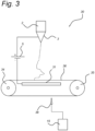
- FIG. 3 schematically shows an electrospinning device 30 according to a further embodiment of the invention.
- the device 30 comprises two rotatable bodies 34, 35, and a looped conveyer belt 36 arranged around the two rotatable bodies 34, 35, wherein the surface of the belt 36 forms the collecting surface / carrier for the fibrous mesh 4.
- the device 30 also comprises a counter electrode 31.
- the electrode 31 may have all sorts of configurations such as for example beam shaped or plate shaped.
- the belt 36 will be made of a polymer and thus exhibit electrically insulating properties.
- the belt 36 should be thin enough for the electric field to pas-trough, but intrinsically will limit the release of charge from the fibrous structure to the counter electrode 31. It is noted that more than two rotatable bodies may be used to guide the belt 36 along the collecting location, the charge or discharge location, and possible some other locations for additional processing of the fibrous structure.
- Figure 3 shows an electrostatic emitter 38, which represents a whole row of a number of electrostatic emitters 38 arranged along the surface of the belt in a direction parallel to a rotation axis of the rotatable bodies 34, 35. Although a number of electrostatic emitters 38 are preferred, only a single electrostatic emitter 38 will already produce a pattern in the fibrous structure. The same accounts for the number of electrostatic emitters 10 of Figure 1 and 2 .
- the collecting surface 4 is arranged between the nozzle 3 and the one or more electrostatic emitters 10, 38.
- This allows to have the collecting surface 4, in combination with the rotatable bodies 6, to face, in turn (i.e. subsequently), the nozzle 3 and the one or more electrostatic emitters 10, 38.
- the electrostatic emitters 10, 38 will have less influence on the area in the electrospinning device where the fibers are formed from the jet exiting the nozzles 3, i.e. the Rayleigh instability area.
- Alternative arrangements are conceivable, as long as the positioning of the electrostatic emitters 10, 38 is such that the formed fibrous structure 8 on the collecting surface 4 is facing the nozzle 3 and the electrostatic emitters 10, 38 in turn (i.e. subsequently during operation).
- Figure 4 shows a flow chart of a method of electrospinning 40 according to a further aspect of the invention.
- the method 40 comprise holding, see step 41, a liquid comprising a polymer melt or a polymer solution in a container. Furthermore the method comprises letting out, see step 42, a stream of the liquid from the container through a nozzle 3. Furthermore the method comprises creating 43 a voltage difference between the nozzle and a collecting surface. Furthermore the method comprises collecting, see step 44, electro spun material coming from the nozzle so as to form a fibrous structure on the collecting surface. Furthermore the method comprises locally distributing, see step 45, positive and/or negative ions onto the fibrous layer by way of one or more static emitters.
- the method comprises rotating the collecting surface by means of one or more rotatable bodies, see step 46, causing the collecting surface to face the nozzle and the one or more static emitters 10 alternately.
- the method shown in Figure 4 also comprises the step of controlling the static emitters so as to form a pattern in the fibrous structure.
- any reference signs placed between parentheses shall not be construed as limiting the claim.
- Use of the verb "comprise” and its conjugations does not exclude the presence of elements or steps other than those stated in a claim.
- the article “a” or “an” preceding an element does not exclude the presence of a plurality of such elements.
- several means are enumerated. These means may be embodied by one and the same item of hardware or software. The mere fact that certain measures are recited in mutually different dependent claims does not indicate that a combination of these measures cannot be used to advantage.
Landscapes
- Engineering & Computer Science (AREA)
- Textile Engineering (AREA)
- Mechanical Engineering (AREA)
- Chemical & Material Sciences (AREA)
- Dispersion Chemistry (AREA)
- Spinning Methods And Devices For Manufacturing Artificial Fibers (AREA)
- Nonwoven Fabrics (AREA)
Description
- The invention relates to an electrospinning device for producing a fibrous structure. The invention also relates to method of electrospinning.
- US patent publication
US2005/224999 discloses an electrospinning device for producing fibrous materials. The device has an extrusion element configured to electrospin a substance using an electric field extraction of the substance from a tip of the extrusion element, a collector, and a chamber enclosing the collector and extrusion element. An ion generator is present to generate ions for injection into a Rayleigh instability zone in the chamber during operation of the device. - US patent publication
US2007/042069 discloses a fiber spinning apparatus for charging a polymer-containing liquid stream using a point-electrode positioned adjacent the intended path of the liquid stream during operation. E.g. an ion flow is generated by a corona discharge to impart electrical charge to the polymer-containing liquid stream. - US patent publication
US2005/104258 discloses an electrospinning device allowing to direct a polymer from a source electrode into an electric field that drives the formation of electrospun fibers that are deposited onto a collecting surface (being a counter electrode or a collecting surface between the source electrode and a counter electrode). Multiple electrically charged areas underneath the counter electrode allow to produce a pattern of areas where fibers are collected. - Electrospinning is a method to produce continuous fibers with a diameter ranging from a few tens of nanometers to a few tens of micrometers. To electrospin fibers, a suitable liquefied material may be fed through a small, electrically conductive nozzle. The liquefied material may be electrically charged by applying a high voltage between the nozzle and a counter electrode. The generated electric field causes a cone-shape deformation of the droplet at the nozzle tip. Once the surface tension of this droplet is overcome by the electrical force, a jet is formed out of the droplet and a fiber forms that moves towards the counter electrode. During the flight towards the counter electrode the fiber is continuously stretched and elongated by the different forces acting on it, reducing its diameter and allowing it to solidify by evaporation of the solvent or cooling of the material such that a solid fiber is deposited on the collector which is placed before the counter electrode or the counter electrode is used as collector directly.
- Electrospinning uses an electric field, generated by a high voltage potential between nozzle and collector, to produce a fiber from a droplet at the nozzle tip. In alternative configurations fibers are drawn e.g. from a liquid bath, liquid covered ball, liquid filled opening or liquid covered wire. After stretching, the fiber is deposited on the collector surface. However, even with conductive collector surfaces, residual electric charges might remain inside the deposited fiber. These residual charges have an adverse effect on the process since they act as a repulsive force on the subsequent section of the fiber arriving at the collector. These residual charges are not always easy to remove efficiently, even with conductive collectors. Eventually, fibers are not in direct contact with the collector anymore but with underlying, poorly conducting fibers.
- Several methods are proposed to improve the removal/neutralization of residual charges at the deposited fibrous structure. However, these methods rely on either reducing charge on the fiber in mid-air, or bombarding the collector surface with ions to alter the charge on the fibrous structure, see e.g. patent publication
WO2016/147951 . InWO2016/147951 a nanofiber manufacturing apparatus is described equipped with a collecting unit, a discharging unit, a power source unit, and an electricity-removing unit. The collecting unit dispenses a deposit-receiving material from one end and collects same at the other end. The discharging unit discharges a feedstock liquid and deposits nanofibers on a collecting surface. The power source unit generates a potential difference between the discharging unit and the collecting surface. The electricity-removing unit removes the charge with which the deposited nanofibers are charged. Rotatable bodies cause the collecting surface to face the discharging unit and the electricity-removing unit alternately. The electricity-removing unit extends across the whole width of the collecting surface. -
WO 2013/106822 A1 describes a system for manufacturing an artificial construct. An antistatic device (e.g., bar) may be incorporated into the process to improve fiber alignment. - It is on object of the present invention to provide an improved electrospinning device.
- Aspects of the invention are defined in the independent claims. The dependent claims define advantageous embodiments.
- A first aspect of the invention provides an electrospinning device comprising:
- a container for holding a liquid comprising a polymer melt or a polymer solution;
- a nozzle arranged to outlet a stream of the liquid from the container;
- a collecting surface for collecting electro spun material coming from the nozzle during an electrospinning process so as to form a fibrous structure on the collecting surface;
- a voltage supply system arranged to create a voltage difference between the nozzle and the collecting surface,
- one or more electrostatic emitters arranged to locally distribute positive and/or negative ions onto the fibrous structure and collector surface, and
- one or more rotatable bodies arranged to cause the collecting surface to face the nozzle and the electrostatic emitters in turn, and
- a control unit arranged to control the one or more electrostatic emitters so as to control an attractiveness or repulsiveness of certain areas of the collector or of the fibrous structure for subsequent fiber deposition to form a local built up of fibers to create a pattern into the fibrous structure.
- The present invention deploys the known technique of using ions to alter the charge on the deposited fibrous structure in a local manner. To obtain this, the one or more electrostatic emitters may be relatively small and positioned close to the surface of the collecting surface/fibrous structure, and have e.g. an effective area around the emitters with a radius of only 5-10mm. This new technique offers precise control over the attractiveness/repulsiveness of certain areas of the collector/fibrous structure for subsequent fiber deposition. This enables a local built up of fibers, which enables patterning of the fibrous structure. So what was regarded previously as a problem (i.e. built up of charge in the fibrous structure during manufacturing) is now used by the inventors to its advantage.
- Optionally, the device comprises a rotatable cylindrical body, the surface of which forms the collecting surface.
- Optionally, the device comprises at least two rotatable bodies, and a looped conveyer belt arranged around the two rotatable bodies, wherein the surface of the belt forms the collecting surface.
- Optionally, the collecting surface is arranged between the nozzle and the one or more electrostatic emitters. This allows to have the collecting surface, in combination with the rotatable bodies to face in turn (i.e. subsequently) the nozzle and the one or more electrostatic emitters. Furthermore, as in this embodiment, the electrostatic emitters are located at the opposite side from the collecting surface when viewed from the nozzle, the electrostatic emitters will have less influence on the area in the electrospinning device where the fibers are formed from the jet exiting the nozzles (the Rayleigh instability area).
- Optionally, the electrostatic emitters are arranged in a row.
- Optionally, the electrostatic emitters are arranged in an array.
- Optionally, the electrostatic emitters are movable in a direction parallel to a rotation axis of the rotatable body or bodies.
- Optionally, the electrostatic emitters comprise ion generators.
- The device comprises a control unit arranged to control the electrostatic emitters so as to create a pattern into the fibrous structure.
- According to a further aspect there is provided a method of electrospinning comprising:
- holding a liquid comprising a polymer melt or a polymer solution in a container;
- letting out a stream of the liquid from the container through at least one nozzle;
- creating a voltage difference between the nozzle and a collecting surface;
- collecting electro spun material coming from the nozzle so as to form a fibrous structure on the collecting surface;
- distributing positive and/or negative ions onto the fibrous structure by way of one or more electrostatic emitters;
- rotating the collecting surface by means of one or more rotatable bodies causing the collecting surface to face the nozzle and the one or more electrostatic emitters in turn; and the method further comprising the step of controlling the electrostatic emitters so as to form a pattern in the fibrous structure.
- These and other aspects of the invention are apparent from and will be elucidated with reference to the embodiments described hereinafter. In the drawings,
-
Figure 1 schematically shows an embodiment of an electrospinning device; -
Figure 2 schematically shows an electrospinning device according to an embodiment of the invention; -
Figure 3 schematically shows an electrospinning device according to a further embodiment of the invention; -
Figure 4 shows a flow chart of a method of electrospinning according to a further aspect of the invention. -
Figure 1 schematically shows an embodiment of anelectrospinning device 1. Theelectrospinning device 1 may be arranged inside an enclosure (not shown inFigure 1 ) for quality or security reasons. Theelectrospinning device 1 may comprises acontainer 2 for holding a liquid comprising a polymer melt or a polymer solution, and anozzle 3 arranged to outlet a stream of the liquid from thecontainer 2. Theelectrospinning device 1 further comprises a collectingsurface 4 for collecting electro spun material coming from thenozzle 3 during an electrospinning process. Avoltage supply system 5 may be arranged to create a voltage difference between the nozzle and the collector. Thevoltage supply system 5 may comprise at least one AC or DC voltage supply to create the voltage difference or it may comprise two voltage supplies, one creating a voltage difference between the collectingsurface 4 and ground and one creating a difference between thenozzle 3 and ground. Due to the applied voltage(s), an electro spun fiber is created that flies from thenozzle 3 to the collectingsurface 4 on which it is collected to form an electro spunfibrous structure 8. - In the embodiment shown in
Figure 1 thedevice 1 also comprises one or moreelectrostatic emitters 10 arranged to locally distribute positive and/or negative ions onto the fibrous structure and/or collector, thereby locally changing the charge of thefibrous structure 8, and so attract or repel the incoming 'flying' fibers. Theelectrostatic emitters 10 are, for example, electrostatic emitters (ionizers) such as ion generators. Furthermore, thedevice 1 comprises arotatable body 6 arranged to cause the collecting surface to face thenozzle 3 and thestatic emitters 10 in turn (or alternately in position, and hence during operation also alternately in time). In this embodiment, the rotatable body is a rotatablecylindrical body 6, the surface of which forms the collectingsurface 4. The rotatablecylindrical body 6 is arranged on ashaft 7 which is driven by a motor (not shown). - In the embodiment shown in
Figure 1 thestatic emitters 10 are arranged in a row. In the example ofFigure 1 , thestatic emitters 10 are arranged in an array with equidistant space between two consecutivestatic emitters 10. Eachstatic emitter 10 is arranged to distribute positive and/or negative ions on thefibrous structure 8 over a distance Di. This distance is smaller than the width W of the rotatablecylindrical body 6, and thus smaller than the width of the collectingsurface 4. It is noted that in other embodiments, thestatic emitters 10 can be arranged having arbitrary intermediate spaces, i.e. non-equidistant spaces. Theelectrostatic emitters 10 may be relatively small, and positioned close to the surface of the collecting surface 4 (and thus fibrous structure 8). The electrostatic emitters are e.g. pin or spike formed, and may have an effective area around theemitters 10 with a radius of only 5-10mm. - The
device 1 also comprises acontrol unit 15 arranged to control thestatic emitters 10 so as to create a pattern into thefibrous structure 8, as will be explained below. - For example, when the tip portion of the
nozzle 3 is positively charged, thefibrous structure 8 deposited on the collectingsurface 4 has a positive charge. In such a case, since the positively chargedfibers 8 repel each other, it is difficult to deposit the fibers consecutively. By locally distributing negative ions on thefiber structure 8, using the negative ion generator, the positive charges of the already deposited fibers can be locally neutralized. As a consequence, once the collecting surface faces thenozzle 3 again, at these locally neutralized locations, the fibers will be attracted, while at the still positively charged locations, the new fibers will be repelled. In this way a pattern can be created into the fiber structure. It is noted that instead of neutralizing certain locations of the fibrous structure, they can be charged negative, giving the same or sometimes even better results. -
Figure 2 schematically shows anelectrospinning device 1 according to an embodiment of the invention. Thedevice 1 is similar to the device shown infigure 1 , except that inFigure 2 thestatic emitters 10 are movable in a direction parallel to a rotation axis of therotatable body 6, i.e. parallel to the longitudinal direction of theshaft 7. This is indicated by arrows. In this example somestatic emitters 11 are stationary, some are movable individually, see 12, and some are movable jointly, see 13. It will be clear to the skilled reader that many combinations of movable and non-movable (static) static emitters are conceivable. - As mentioned above with reference to
Figure 1 , by providing positive or negative ions onto the fibrous structure respectively collecting surface, the fibrous structure is locally charged or discharged. Thecontrol unit 15 may be arranged to control thestatic emitters 10 so as to create a pattern into thefibrous structure 8. For example, in a first stage, thecontrol unit 15 may equally activate all of thestatic emitters 10, which may cover the whole of the width W of the collectingsurface 4. This will result in a substantially flat layer of fibers on the collectingsurface 4. In a second stage, thecontrol unit 15 may activate two of thestatic emitters 10 remote from each other with a distance L, and having an effective discharge area of Di and Dj. Once the second stage progresses, the fibrous structure will contain a bottom layer with two rims on it having a real valued distance K of about K = L - Di/2 - Dj/2. In this way all kind of pattern with rings can be manufactured. By switching between the individual emitters during the rotation of the collector other projected patterns (not limited by) like squares, stripes and circles are possible. -
Figure 3 schematically shows anelectrospinning device 30 according to a further embodiment of the invention. Thedevice 30 comprises tworotatable bodies conveyer belt 36 arranged around the tworotatable bodies belt 36 forms the collecting surface / carrier for thefibrous mesh 4. In the embodiment ofFigure 3 , thedevice 30 also comprises acounter electrode 31. By applying a voltage difference between thenozzle 3 and thecounter electrode 31, an electrical field is created between thenozzle 3 and the collectingsurface 4 when situated between thenozzle 3 and theelectrode 31. Theelectrode 31 may have all sorts of configurations such as for example beam shaped or plate shaped. In an embodiment thebelt 36 will be made of a polymer and thus exhibit electrically insulating properties. - The
belt 36 should be thin enough for the electric field to pas-trough, but intrinsically will limit the release of charge from the fibrous structure to thecounter electrode 31. It is noted that more than two rotatable bodies may be used to guide thebelt 36 along the collecting location, the charge or discharge location, and possible some other locations for additional processing of the fibrous structure. -
Figure 3 shows anelectrostatic emitter 38, which represents a whole row of a number ofelectrostatic emitters 38 arranged along the surface of the belt in a direction parallel to a rotation axis of therotatable bodies electrostatic emitters 38 are preferred, only a singleelectrostatic emitter 38 will already produce a pattern in the fibrous structure. The same accounts for the number ofelectrostatic emitters 10 ofFigure 1 and2 . - In the embodiments shown in
Figure 1-3 the collectingsurface 4 is arranged between thenozzle 3 and the one or moreelectrostatic emitters surface 4, in combination with therotatable bodies 6, to face, in turn (i.e. subsequently), thenozzle 3 and the one or moreelectrostatic emitters electrostatic emitters surface 4 when viewed from thenozzle 3, theelectrostatic emitters nozzles 3, i.e. the Rayleigh instability area. Alternative arrangements are conceivable, as long as the positioning of theelectrostatic emitters fibrous structure 8 on the collectingsurface 4 is facing thenozzle 3 and theelectrostatic emitters -
Figure 4 shows a flow chart of a method ofelectrospinning 40 according to a further aspect of the invention. Themethod 40 comprise holding, seestep 41, a liquid comprising a polymer melt or a polymer solution in a container. Furthermore the method comprises letting out, seestep 42, a stream of the liquid from the container through anozzle 3. Furthermore the method comprises creating 43 a voltage difference between the nozzle and a collecting surface. Furthermore the method comprises collecting, seestep 44, electro spun material coming from the nozzle so as to form a fibrous structure on the collecting surface. Furthermore the method comprises locally distributing, seestep 45, positive and/or negative ions onto the fibrous layer by way of one or more static emitters. - Finally, the method comprises rotating the collecting surface by means of one or more rotatable bodies, see
step 46, causing the collecting surface to face the nozzle and the one or morestatic emitters 10 alternately. - The method shown in
Figure 4 also comprises the step of controlling the static emitters so as to form a pattern in the fibrous structure. - In the claims, any reference signs placed between parentheses shall not be construed as limiting the claim. Use of the verb "comprise" and its conjugations does not exclude the presence of elements or steps other than those stated in a claim. The article "a" or "an" preceding an element does not exclude the presence of a plurality of such elements. In the device claims several means are enumerated. These means may be embodied by one and the same item of hardware or software. The mere fact that certain measures are recited in mutually different dependent claims does not indicate that a combination of these measures cannot be used to advantage.
Claims (9)
- An electrospinning device (1; 30) comprising:- a container (2) for holding a liquid comprising a polymer melt or a polymer solution;- a nozzle (3) arranged to outlet a stream of the liquid from the container;- a collecting surface (4) for collecting electro spun material coming from the nozzle during an electrospinning process so as to form a fibrous structure (8) on the collecting surface (4);- a voltage supply system (5) arranged to create a voltage difference between the nozzle (3) and the collecting surface (4),- one or more electrostatic emitters (10; 38) arranged to locally distribute positive and/or negative ions onto the fibrous structure (8),- one or more rotatable bodies (6; 36) arranged to cause the collecting surface (4) to face the nozzle (3) and the electrostatic emitters (10; 38) in turn, and- a control unit arranged to control the one or more electrostatic emitters so as to control an attractiveness or repulsiveness of certain areas of the collector or of the fibrous structure for subsequent fiber deposition to form a local built up of fibers to create a pattern into the fibrous structure.
- The electrospinning device (1; 30) according to claim 1, wherein the device comprises a rotatable cylindrical body (6), the surface of which forms the collecting surface (4).
- The electrospinning device (1; 30) according to claim 1, wherein the device comprises at least two rotatable bodies (34, 35), and a looped conveyer belt (36) arranged around the two rotatable bodies (34, 35), wherein the surface of the belt (36) forms the collecting surface (4).
- The electrospinning device (1; 30) according to any one of claims 1-3, wherein the collecting surface (4) is arranged between the nozzle (3) and the one or more electrostatic emitters (10; 38).
- The electrospinning device (1; 30) according to any one of the preceding claims, wherein the electrostatic emitters (10) are arranged in a row.
- The electrospinning device (1; 30) according to claim 5, wherein the electrostatic emitters (10) are arranged in an array.
- The electrospinning device (1; 30) according to any one of the preceding claims, wherein the electrostatic emitters (10) are movable in a direction parallel to a rotation axis of the rotatable body or bodies.
- The electrospinning device (1; 30) according to any one of the preceding claims, wherein the electrostatic emitters (10) comprise ion generators.
- A method of electrospinning (40) comprising:- holding (41) a liquid comprising a polymer melt or a polymer solution in a container;- letting out (42) a stream of the liquid from the container through at least one nozzle (3);- creating (43) a voltage difference between the nozzle and a collecting surface (4);- collecting (44) electro spun material coming from the nozzle (3) so as to form a fibrous structure (8) on the collecting surface (4);- locally distributing (45) positive and/or negative ions onto the fibrous structure, respectively collecting surface (4) by way of one or more electrostatic emitters (10; 38);- controlling the one or more electrostatic emitters so as to control an attractiveness or repulsiveness of certain areas of the collector or of the fibrous structure for subsequent fiber deposition to form a local built up of fibers to create a pattern into the fibrous structure; and- rotating (46) the collecting surface (4) by means of one or more rotatable bodies causing the collecting surface to face the nozzle and the one or more electrostatic emitters(10) in turn.
Applications Claiming Priority (2)
| Application Number | Priority Date | Filing Date | Title |
|---|---|---|---|
| NL2019764A NL2019764B1 (en) | 2017-10-19 | 2017-10-19 | Electrospinning device and method |
| PCT/NL2018/050688 WO2019078720A1 (en) | 2017-10-19 | 2018-10-19 | Electrospinning device and method |
Publications (2)
| Publication Number | Publication Date |
|---|---|
| EP3697956A1 EP3697956A1 (en) | 2020-08-26 |
| EP3697956B1 true EP3697956B1 (en) | 2024-09-11 |
Family
ID=60515769
Family Applications (1)
| Application Number | Title | Priority Date | Filing Date |
|---|---|---|---|
| EP18812358.2A Active EP3697956B1 (en) | 2017-10-19 | 2018-10-19 | Electrospinning device and method |
Country Status (8)
| Country | Link |
|---|---|
| US (1) | US11384452B2 (en) |
| EP (1) | EP3697956B1 (en) |
| CN (1) | CN111247281B (en) |
| ES (1) | ES2993446T3 (en) |
| NL (1) | NL2019764B1 (en) |
| PL (1) | PL3697956T3 (en) |
| WO (1) | WO2019078720A1 (en) |
| ZA (1) | ZA202002888B (en) |
Families Citing this family (3)
| Publication number | Priority date | Publication date | Assignee | Title |
|---|---|---|---|---|
| CN110424057B (en) * | 2019-08-12 | 2022-05-10 | 广东工业大学 | Electrospinning deposition method and system |
| EP3944914A1 (en) * | 2020-07-30 | 2022-02-02 | Max-Planck-Gesellschaft zur Förderung der Wissenschaften e.V. | Nozzle and method for forming microdroplets |
| JP7689302B2 (en) * | 2021-05-19 | 2025-06-06 | パナソニックIpマネジメント株式会社 | Fiber assembly manufacturing apparatus and method |
Citations (1)
| Publication number | Priority date | Publication date | Assignee | Title |
|---|---|---|---|---|
| WO2013106822A1 (en) * | 2012-01-12 | 2013-07-18 | Johnson Jed K | Nanofiber scaffolds for biological structures |
Family Cites Families (30)
| Publication number | Priority date | Publication date | Assignee | Title |
|---|---|---|---|---|
| US2187306A (en) * | 1937-07-28 | 1940-01-16 | Richard Schreiber Gastell | Artificial thread and method of producing same |
| US3387326A (en) * | 1964-06-04 | 1968-06-11 | Du Pont | Apparatus for charging and spreading a web |
| US3320479A (en) * | 1965-05-24 | 1967-05-16 | Du Pont | Charged web collecting apparatus |
| US5254297A (en) * | 1992-07-15 | 1993-10-19 | Exxon Chemical Patents Inc. | Charging method for meltblown webs |
| US5296172A (en) * | 1992-07-31 | 1994-03-22 | E. I. Du Pont De Nemours And Company | Electrostatic field enhancing process and apparatus for improved web pinning |
| US5643524A (en) * | 1994-12-30 | 1997-07-01 | E. I. Du Pont De Nemours And Company | Corona charging of flash spun plexifilamentary film-fibril webs in poor charging environments |
| US20020090725A1 (en) * | 2000-11-17 | 2002-07-11 | Simpson David G. | Electroprocessed collagen |
| US20050104258A1 (en) * | 2003-07-02 | 2005-05-19 | Physical Sciences, Inc. | Patterned electrospinning |
| US7297305B2 (en) * | 2004-04-08 | 2007-11-20 | Research Triangle Institute | Electrospinning in a controlled gaseous environment |
| US7465159B2 (en) * | 2005-08-17 | 2008-12-16 | E.I. Du Pont De Nemours And Company | Fiber charging apparatus |
| WO2007084742A2 (en) * | 2006-01-20 | 2007-07-26 | University Of Akron | Method of making coiled and buckled electrospun fiber structures |
| WO2008151117A1 (en) * | 2007-06-01 | 2008-12-11 | United States Of America As Represented By The Administrator Of The National Aeronautics And Space Administration | Method and system for aligning fibers during electrospinning |
| US20090091065A1 (en) * | 2007-10-09 | 2009-04-09 | Indian Institute Of Technology Kanpur | Electrospinning Apparatus For Producing Nanofibers and Process Thereof |
| JP4763845B2 (en) * | 2009-09-09 | 2011-08-31 | パナソニック株式会社 | Nanofiber manufacturing apparatus and nanofiber manufacturing method |
| AU2010319039A1 (en) * | 2009-11-11 | 2012-05-17 | Teijin Limited | Molded fiber article |
| US9656417B2 (en) * | 2010-12-29 | 2017-05-23 | Neograft Technologies, Inc. | System and method for mandrel-less electrospinning |
| CZ303380B6 (en) * | 2011-06-27 | 2012-08-22 | Contipro Biotech S.R.O. | Process for producing materials exhibiting anisotropic properties and composed of nanofibers or microfibers and apparatus for making the same |
| US9091007B2 (en) * | 2012-12-10 | 2015-07-28 | Taipei Medical University | Electrospinning apparatus with a sideway motion device and a method of using the same |
| CZ2012907A3 (en) * | 2012-12-17 | 2013-11-13 | Technická univerzita v Liberci | Process for preparing polymeric nanofibers by spinning a solution of polymer melt in electric field and linear form of polymeric nanofibers prepared in such a manner |
| US20160325480A1 (en) * | 2013-12-31 | 2016-11-10 | Neograft Technologies, Inc. | Self-diagnostic graft production systems and related methods |
| US10633766B2 (en) * | 2014-08-18 | 2020-04-28 | University of Central Oklahoma | Method and apparatus for collecting cross-aligned fiber threads |
| US10640888B1 (en) * | 2019-07-02 | 2020-05-05 | University of Central Oklahoma | Method and apparatus for accumulating cross-aligned fiber in an electrospinning device |
| US10415156B2 (en) * | 2014-08-18 | 2019-09-17 | University of Central Oklahoma | Method and apparatus for controlled alignment and deposition of branched electrospun fiber |
| JP6010164B2 (en) | 2015-03-18 | 2016-10-19 | 株式会社東芝 | Nanofiber manufacturing apparatus and nanofiber manufacturing method |
| GB201513328D0 (en) * | 2015-07-29 | 2015-09-09 | Univ Surrey | An Electrospinning Device and Configuration Method |
| US20180368968A1 (en) * | 2015-12-21 | 2018-12-27 | Neograft Technologies, Inc. | System for creating a graft device |
| US20170260652A1 (en) * | 2016-03-14 | 2017-09-14 | Kabushiki Kaisha Toshiba | Nozzle head and electrospinning apparatus |
| JP6612664B2 (en) * | 2016-03-16 | 2019-11-27 | 株式会社東芝 | Fiber orientation sheet |
| US11028502B2 (en) * | 2017-11-02 | 2021-06-08 | Wake Forest University Health Sciences | Vascular constructs |
| JP2019167641A (en) * | 2018-03-22 | 2019-10-03 | パナソニックIpマネジメント株式会社 | Electrospinning device and manufacturing method of fiber assembly |
-
2017
- 2017-10-19 NL NL2019764A patent/NL2019764B1/en active
-
2018
- 2018-10-19 WO PCT/NL2018/050688 patent/WO2019078720A1/en not_active Ceased
- 2018-10-19 US US16/756,474 patent/US11384452B2/en active Active
- 2018-10-19 CN CN201880068440.7A patent/CN111247281B/en active Active
- 2018-10-19 PL PL18812358.2T patent/PL3697956T3/en unknown
- 2018-10-19 ES ES18812358T patent/ES2993446T3/en active Active
- 2018-10-19 EP EP18812358.2A patent/EP3697956B1/en active Active
-
2020
- 2020-05-18 ZA ZA2020/02888A patent/ZA202002888B/en unknown
Patent Citations (1)
| Publication number | Priority date | Publication date | Assignee | Title |
|---|---|---|---|---|
| WO2013106822A1 (en) * | 2012-01-12 | 2013-07-18 | Johnson Jed K | Nanofiber scaffolds for biological structures |
Also Published As
| Publication number | Publication date |
|---|---|
| EP3697956A1 (en) | 2020-08-26 |
| US11384452B2 (en) | 2022-07-12 |
| PL3697956T3 (en) | 2025-02-10 |
| ZA202002888B (en) | 2025-11-26 |
| ES2993446T3 (en) | 2024-12-30 |
| WO2019078720A1 (en) | 2019-04-25 |
| CN111247281A (en) | 2020-06-05 |
| US20210198808A1 (en) | 2021-07-01 |
| CN111247281B (en) | 2022-12-16 |
| NL2019764B1 (en) | 2019-04-29 |
Similar Documents
| Publication | Publication Date | Title |
|---|---|---|
| JP5111525B2 (en) | Method and apparatus for producing nanoparticle layers or nanofiber layers from polymer solutions or melts | |
| US11384452B2 (en) | Electrospinning device and method | |
| EP2402487B1 (en) | Roller type electrostatic spinning apparatus | |
| KR102267119B1 (en) | Spray charging and discharging system for polymer spray deposition device | |
| KR101307877B1 (en) | Electret filter element and method for the production thereof | |
| CZ299537B6 (en) | Method of and apparatus for producing nanofibers from polymeric solution using electrostatic spinning | |
| WO2011070761A1 (en) | Apparatus for producing nano-fiber and method for producing nano-fiber | |
| WO2005042813A1 (en) | Electrostatic spinning equipment and method of preparing nano fiber using the same | |
| Yousefzadeh et al. | Modelling performance of electrospun nanofibres and nanofibrous assemblies | |
| CZ2007727A3 (en) | Collecting electrode of a device for producing nanofibers by electrostatic spinning of polymer matrices and device comprising such collecting electrode | |
| JP2007277775A (en) | Electrostatic spraying apparatus and electrostatic spraying method | |
| US7517479B2 (en) | Method of utilizing MEMS based devices to produce electrospun fibers for commercial, industrial and medical use | |
| US9138931B2 (en) | Collector device, non-woven fabric manufacturing apparatus, and non-woven fabric manufacturing method | |
| JP4797652B2 (en) | Electrostatic spray device and electrostatic spray monitoring method | |
| EP3697948B1 (en) | Electro hydrodynamic production method and system | |
| JP2010144290A (en) | Method for producing nanofiber and production apparatus | |
| WO2016098869A1 (en) | Apparatus for producing nano-fiber and method for producing nano-fiber | |
| JP4508105B2 (en) | Electrostatic spraying equipment | |
| JP2018059221A (en) | Sheet-like fiber deposit manufacturing apparatus and method for manufacturing the fiber deposit | |
| JP2024072628A (en) | Fiber sheet manufacturing method and manufacturing device | |
| JP2024072627A (en) | Fiber sheet manufacturing method and manufacturing device | |
| JPH07161451A (en) | Earth electrode for corona discharge generating device | |
| CN107849741A (en) | A kind of electrostatic for the fibril that is used to entwining is entwined equipment and technique | |
| JPS59204958A (en) | Opening of filament group |
Legal Events
| Date | Code | Title | Description |
|---|---|---|---|
| STAA | Information on the status of an ep patent application or granted ep patent |
Free format text: STATUS: UNKNOWN |
|
| STAA | Information on the status of an ep patent application or granted ep patent |
Free format text: STATUS: THE INTERNATIONAL PUBLICATION HAS BEEN MADE |
|
| TPAC | Observations filed by third parties |
Free format text: ORIGINAL CODE: EPIDOSNTIPA |
|
| PUAI | Public reference made under article 153(3) epc to a published international application that has entered the european phase |
Free format text: ORIGINAL CODE: 0009012 |
|
| STAA | Information on the status of an ep patent application or granted ep patent |
Free format text: STATUS: REQUEST FOR EXAMINATION WAS MADE |
|
| 17P | Request for examination filed |
Effective date: 20200518 |
|
| AK | Designated contracting states |
Kind code of ref document: A1 Designated state(s): AL AT BE BG CH CY CZ DE DK EE ES FI FR GB GR HR HU IE IS IT LI LT LU LV MC MK MT NL NO PL PT RO RS SE SI SK SM TR |
|
| AX | Request for extension of the european patent |
Extension state: BA ME |
|
| DAV | Request for validation of the european patent (deleted) | ||
| DAX | Request for extension of the european patent (deleted) | ||
| STAA | Information on the status of an ep patent application or granted ep patent |
Free format text: STATUS: EXAMINATION IS IN PROGRESS |
|
| 17Q | First examination report despatched |
Effective date: 20210608 |
|
| REG | Reference to a national code |
Ref country code: DE Ref legal event code: R079 Free format text: PREVIOUS MAIN CLASS: D04H0001728000 Ipc: D01D0005000000 Ref country code: DE Ref legal event code: R079 Ref document number: 602018074317 Country of ref document: DE Free format text: PREVIOUS MAIN CLASS: D04H0001728000 Ipc: D01D0005000000 |
|
| GRAP | Despatch of communication of intention to grant a patent |
Free format text: ORIGINAL CODE: EPIDOSNIGR1 |
|
| STAA | Information on the status of an ep patent application or granted ep patent |
Free format text: STATUS: GRANT OF PATENT IS INTENDED |
|
| RIC1 | Information provided on ipc code assigned before grant |
Ipc: B05B 5/00 20060101ALI20240314BHEP Ipc: D04H 1/728 20120101ALI20240314BHEP Ipc: B05B 5/025 20060101ALI20240314BHEP Ipc: D01D 5/00 20060101AFI20240314BHEP |
|
| INTG | Intention to grant announced |
Effective date: 20240411 |
|
| GRAS | Grant fee paid |
Free format text: ORIGINAL CODE: EPIDOSNIGR3 |
|
| GRAA | (expected) grant |
Free format text: ORIGINAL CODE: 0009210 |
|
| STAA | Information on the status of an ep patent application or granted ep patent |
Free format text: STATUS: THE PATENT HAS BEEN GRANTED |
|
| AK | Designated contracting states |
Kind code of ref document: B1 Designated state(s): AL AT BE BG CH CY CZ DE DK EE ES FI FR GB GR HR HU IE IS IT LI LT LU LV MC MK MT NL NO PL PT RO RS SE SI SK SM TR |
|
| P01 | Opt-out of the competence of the unified patent court (upc) registered |
Free format text: CASE NUMBER: APP_44785/2024 Effective date: 20240801 |
|
| REG | Reference to a national code |
Ref country code: GB Ref legal event code: FG4D |
|
| REG | Reference to a national code |
Ref country code: CH Ref legal event code: EP |
|
| REG | Reference to a national code |
Ref country code: DE Ref legal event code: R096 Ref document number: 602018074317 Country of ref document: DE |
|
| REG | Reference to a national code |
Ref country code: NL Ref legal event code: FP Ref country code: IE Ref legal event code: FG4D |
|
| REG | Reference to a national code |
Ref country code: ES Ref legal event code: FG2A Ref document number: 2993446 Country of ref document: ES Kind code of ref document: T3 Effective date: 20241230 |
|
| REG | Reference to a national code |
Ref country code: LT Ref legal event code: MG9D |
|
| PG25 | Lapsed in a contracting state [announced via postgrant information from national office to epo] |
Ref country code: NO Free format text: LAPSE BECAUSE OF FAILURE TO SUBMIT A TRANSLATION OF THE DESCRIPTION OR TO PAY THE FEE WITHIN THE PRESCRIBED TIME-LIMIT Effective date: 20241211 |
|
| PG25 | Lapsed in a contracting state [announced via postgrant information from national office to epo] |
Ref country code: GR Free format text: LAPSE BECAUSE OF FAILURE TO SUBMIT A TRANSLATION OF THE DESCRIPTION OR TO PAY THE FEE WITHIN THE PRESCRIBED TIME-LIMIT Effective date: 20241212 Ref country code: FI Free format text: LAPSE BECAUSE OF FAILURE TO SUBMIT A TRANSLATION OF THE DESCRIPTION OR TO PAY THE FEE WITHIN THE PRESCRIBED TIME-LIMIT Effective date: 20240911 |
|
| PG25 | Lapsed in a contracting state [announced via postgrant information from national office to epo] |
Ref country code: BG Free format text: LAPSE BECAUSE OF FAILURE TO SUBMIT A TRANSLATION OF THE DESCRIPTION OR TO PAY THE FEE WITHIN THE PRESCRIBED TIME-LIMIT Effective date: 20240911 |
|
| PG25 | Lapsed in a contracting state [announced via postgrant information from national office to epo] |
Ref country code: LV Free format text: LAPSE BECAUSE OF FAILURE TO SUBMIT A TRANSLATION OF THE DESCRIPTION OR TO PAY THE FEE WITHIN THE PRESCRIBED TIME-LIMIT Effective date: 20240911 |
|
| PG25 | Lapsed in a contracting state [announced via postgrant information from national office to epo] |
Ref country code: HR Free format text: LAPSE BECAUSE OF FAILURE TO SUBMIT A TRANSLATION OF THE DESCRIPTION OR TO PAY THE FEE WITHIN THE PRESCRIBED TIME-LIMIT Effective date: 20240911 |
|
| PG25 | Lapsed in a contracting state [announced via postgrant information from national office to epo] |
Ref country code: RS Free format text: LAPSE BECAUSE OF FAILURE TO SUBMIT A TRANSLATION OF THE DESCRIPTION OR TO PAY THE FEE WITHIN THE PRESCRIBED TIME-LIMIT Effective date: 20241211 |
|
| PG25 | Lapsed in a contracting state [announced via postgrant information from national office to epo] |
Ref country code: RS Free format text: LAPSE BECAUSE OF FAILURE TO SUBMIT A TRANSLATION OF THE DESCRIPTION OR TO PAY THE FEE WITHIN THE PRESCRIBED TIME-LIMIT Effective date: 20241211 Ref country code: NO Free format text: LAPSE BECAUSE OF FAILURE TO SUBMIT A TRANSLATION OF THE DESCRIPTION OR TO PAY THE FEE WITHIN THE PRESCRIBED TIME-LIMIT Effective date: 20241211 Ref country code: LV Free format text: LAPSE BECAUSE OF FAILURE TO SUBMIT A TRANSLATION OF THE DESCRIPTION OR TO PAY THE FEE WITHIN THE PRESCRIBED TIME-LIMIT Effective date: 20240911 Ref country code: HR Free format text: LAPSE BECAUSE OF FAILURE TO SUBMIT A TRANSLATION OF THE DESCRIPTION OR TO PAY THE FEE WITHIN THE PRESCRIBED TIME-LIMIT Effective date: 20240911 Ref country code: GR Free format text: LAPSE BECAUSE OF FAILURE TO SUBMIT A TRANSLATION OF THE DESCRIPTION OR TO PAY THE FEE WITHIN THE PRESCRIBED TIME-LIMIT Effective date: 20241212 Ref country code: FI Free format text: LAPSE BECAUSE OF FAILURE TO SUBMIT A TRANSLATION OF THE DESCRIPTION OR TO PAY THE FEE WITHIN THE PRESCRIBED TIME-LIMIT Effective date: 20240911 Ref country code: BG Free format text: LAPSE BECAUSE OF FAILURE TO SUBMIT A TRANSLATION OF THE DESCRIPTION OR TO PAY THE FEE WITHIN THE PRESCRIBED TIME-LIMIT Effective date: 20240911 |
|
| REG | Reference to a national code |
Ref country code: AT Ref legal event code: MK05 Ref document number: 1722744 Country of ref document: AT Kind code of ref document: T Effective date: 20240911 |
|
| PG25 | Lapsed in a contracting state [announced via postgrant information from national office to epo] |
Ref country code: PT Free format text: LAPSE BECAUSE OF FAILURE TO SUBMIT A TRANSLATION OF THE DESCRIPTION OR TO PAY THE FEE WITHIN THE PRESCRIBED TIME-LIMIT Effective date: 20250113 Ref country code: IS Free format text: LAPSE BECAUSE OF FAILURE TO SUBMIT A TRANSLATION OF THE DESCRIPTION OR TO PAY THE FEE WITHIN THE PRESCRIBED TIME-LIMIT Effective date: 20250111 |
|
| PG25 | Lapsed in a contracting state [announced via postgrant information from national office to epo] |
Ref country code: RO Free format text: LAPSE BECAUSE OF FAILURE TO SUBMIT A TRANSLATION OF THE DESCRIPTION OR TO PAY THE FEE WITHIN THE PRESCRIBED TIME-LIMIT Effective date: 20240911 Ref country code: SM Free format text: LAPSE BECAUSE OF FAILURE TO SUBMIT A TRANSLATION OF THE DESCRIPTION OR TO PAY THE FEE WITHIN THE PRESCRIBED TIME-LIMIT Effective date: 20240911 |
|
| PG25 | Lapsed in a contracting state [announced via postgrant information from national office to epo] |
Ref country code: EE Free format text: LAPSE BECAUSE OF FAILURE TO SUBMIT A TRANSLATION OF THE DESCRIPTION OR TO PAY THE FEE WITHIN THE PRESCRIBED TIME-LIMIT Effective date: 20240911 Ref country code: AT Free format text: LAPSE BECAUSE OF FAILURE TO SUBMIT A TRANSLATION OF THE DESCRIPTION OR TO PAY THE FEE WITHIN THE PRESCRIBED TIME-LIMIT Effective date: 20240911 |
|
| PG25 | Lapsed in a contracting state [announced via postgrant information from national office to epo] |
Ref country code: SK Free format text: LAPSE BECAUSE OF FAILURE TO SUBMIT A TRANSLATION OF THE DESCRIPTION OR TO PAY THE FEE WITHIN THE PRESCRIBED TIME-LIMIT Effective date: 20240911 |
|
| REG | Reference to a national code |
Ref country code: CH Ref legal event code: PL |
|
| REG | Reference to a national code |
Ref country code: DE Ref legal event code: R097 Ref document number: 602018074317 Country of ref document: DE |
|
| PG25 | Lapsed in a contracting state [announced via postgrant information from national office to epo] |
Ref country code: MC Free format text: LAPSE BECAUSE OF FAILURE TO SUBMIT A TRANSLATION OF THE DESCRIPTION OR TO PAY THE FEE WITHIN THE PRESCRIBED TIME-LIMIT Effective date: 20240911 |
|
| PG25 | Lapsed in a contracting state [announced via postgrant information from national office to epo] |
Ref country code: DK Free format text: LAPSE BECAUSE OF FAILURE TO SUBMIT A TRANSLATION OF THE DESCRIPTION OR TO PAY THE FEE WITHIN THE PRESCRIBED TIME-LIMIT Effective date: 20240911 |
|
| PG25 | Lapsed in a contracting state [announced via postgrant information from national office to epo] |
Ref country code: LU Free format text: LAPSE BECAUSE OF NON-PAYMENT OF DUE FEES Effective date: 20241019 |
|
| PLBE | No opposition filed within time limit |
Free format text: ORIGINAL CODE: 0009261 |
|
| STAA | Information on the status of an ep patent application or granted ep patent |
Free format text: STATUS: NO OPPOSITION FILED WITHIN TIME LIMIT |
|
| PG25 | Lapsed in a contracting state [announced via postgrant information from national office to epo] |
Ref country code: CH Free format text: LAPSE BECAUSE OF NON-PAYMENT OF DUE FEES Effective date: 20241031 |
|
| 26N | No opposition filed |
Effective date: 20250612 |
|
| PG25 | Lapsed in a contracting state [announced via postgrant information from national office to epo] |
Ref country code: SE Free format text: LAPSE BECAUSE OF FAILURE TO SUBMIT A TRANSLATION OF THE DESCRIPTION OR TO PAY THE FEE WITHIN THE PRESCRIBED TIME-LIMIT Effective date: 20240911 |
|
| PGFP | Annual fee paid to national office [announced via postgrant information from national office to epo] |
Ref country code: NL Payment date: 20251010 Year of fee payment: 8 |
|
| PGFP | Annual fee paid to national office [announced via postgrant information from national office to epo] |
Ref country code: DE Payment date: 20251028 Year of fee payment: 8 |
|
| PGFP | Annual fee paid to national office [announced via postgrant information from national office to epo] |
Ref country code: GB Payment date: 20251023 Year of fee payment: 8 |
|
| PGFP | Annual fee paid to national office [announced via postgrant information from national office to epo] |
Ref country code: IT Payment date: 20251022 Year of fee payment: 8 |
|
| PGFP | Annual fee paid to national office [announced via postgrant information from national office to epo] |
Ref country code: FR Payment date: 20251027 Year of fee payment: 8 |
|
| PGFP | Annual fee paid to national office [announced via postgrant information from national office to epo] |
Ref country code: BE Payment date: 20251024 Year of fee payment: 8 |
|
| PGFP | Annual fee paid to national office [announced via postgrant information from national office to epo] |
Ref country code: IE Payment date: 20251020 Year of fee payment: 8 Ref country code: CZ Payment date: 20251002 Year of fee payment: 8 |
|
| PGFP | Annual fee paid to national office [announced via postgrant information from national office to epo] |
Ref country code: PL Payment date: 20251013 Year of fee payment: 8 |
|
| PG25 | Lapsed in a contracting state [announced via postgrant information from national office to epo] |
Ref country code: CY Free format text: LAPSE BECAUSE OF FAILURE TO SUBMIT A TRANSLATION OF THE DESCRIPTION OR TO PAY THE FEE WITHIN THE PRESCRIBED TIME-LIMIT; INVALID AB INITIO Effective date: 20181019 |
|
| PGFP | Annual fee paid to national office [announced via postgrant information from national office to epo] |
Ref country code: ES Payment date: 20251118 Year of fee payment: 8 |
|
| PG25 | Lapsed in a contracting state [announced via postgrant information from national office to epo] |
Ref country code: HU Free format text: LAPSE BECAUSE OF FAILURE TO SUBMIT A TRANSLATION OF THE DESCRIPTION OR TO PAY THE FEE WITHIN THE PRESCRIBED TIME-LIMIT; INVALID AB INITIO Effective date: 20181019 |