EP3697629B1 - Assemblage - Google Patents
Assemblage Download PDFInfo
- Publication number
- EP3697629B1 EP3697629B1 EP18800700.9A EP18800700A EP3697629B1 EP 3697629 B1 EP3697629 B1 EP 3697629B1 EP 18800700 A EP18800700 A EP 18800700A EP 3697629 B1 EP3697629 B1 EP 3697629B1
- Authority
- EP
- European Patent Office
- Prior art keywords
- securing element
- assembly
- axis
- filamentary elements
- manufacturing
- Prior art date
- Legal status (The legal status is an assumption and is not a legal conclusion. Google has not performed a legal analysis and makes no representation as to the accuracy of the status listed.)
- Active
Links
Images


Classifications
-
- B—PERFORMING OPERATIONS; TRANSPORTING
- B60—VEHICLES IN GENERAL
- B60C—VEHICLE TYRES; TYRE INFLATION; TYRE CHANGING; CONNECTING VALVES TO INFLATABLE ELASTIC BODIES IN GENERAL; DEVICES OR ARRANGEMENTS RELATED TO TYRES
- B60C3/00—Tyres characterised by the transverse section
- B60C3/02—Closed, e.g. toroidal, tyres
-
- B—PERFORMING OPERATIONS; TRANSPORTING
- B32—LAYERED PRODUCTS
- B32B—LAYERED PRODUCTS, i.e. PRODUCTS BUILT-UP OF STRATA OF FLAT OR NON-FLAT, e.g. CELLULAR OR HONEYCOMB, FORM
- B32B5/00—Layered products characterised by the non- homogeneity or physical structure, i.e. comprising a fibrous, filamentary, particulate or foam layer; Layered products characterised by having a layer differing constitutionally or physically in different parts
- B32B5/02—Layered products characterised by the non- homogeneity or physical structure, i.e. comprising a fibrous, filamentary, particulate or foam layer; Layered products characterised by having a layer differing constitutionally or physically in different parts characterised by structural features of a fibrous or filamentary layer
- B32B5/06—Layered products characterised by the non- homogeneity or physical structure, i.e. comprising a fibrous, filamentary, particulate or foam layer; Layered products characterised by having a layer differing constitutionally or physically in different parts characterised by structural features of a fibrous or filamentary layer characterised by a fibrous or filamentary layer mechanically connected, e.g. by needling to another layer, e.g. of fibres, of paper
- B32B5/073—Layered products characterised by the non- homogeneity or physical structure, i.e. comprising a fibrous, filamentary, particulate or foam layer; Layered products characterised by having a layer differing constitutionally or physically in different parts characterised by structural features of a fibrous or filamentary layer characterised by a fibrous or filamentary layer mechanically connected, e.g. by needling to another layer, e.g. of fibres, of paper characterised by the fibrous or filamentary layer being mechanically connected to another layer by sewing, stitching, hook-and-loop fastening or stitchbonding
-
- B—PERFORMING OPERATIONS; TRANSPORTING
- B32—LAYERED PRODUCTS
- B32B—LAYERED PRODUCTS, i.e. PRODUCTS BUILT-UP OF STRATA OF FLAT OR NON-FLAT, e.g. CELLULAR OR HONEYCOMB, FORM
- B32B5/00—Layered products characterised by the non- homogeneity or physical structure, i.e. comprising a fibrous, filamentary, particulate or foam layer; Layered products characterised by having a layer differing constitutionally or physically in different parts
- B32B5/22—Layered products characterised by the non- homogeneity or physical structure, i.e. comprising a fibrous, filamentary, particulate or foam layer; Layered products characterised by having a layer differing constitutionally or physically in different parts characterised by the presence of two or more layers which are next to each other and are fibrous, filamentary, formed of particles or foamed
- B32B5/24—Layered products characterised by the non- homogeneity or physical structure, i.e. comprising a fibrous, filamentary, particulate or foam layer; Layered products characterised by having a layer differing constitutionally or physically in different parts characterised by the presence of two or more layers which are next to each other and are fibrous, filamentary, formed of particles or foamed one layer being a fibrous or filamentary layer
- B32B5/26—Layered products characterised by the non- homogeneity or physical structure, i.e. comprising a fibrous, filamentary, particulate or foam layer; Layered products characterised by having a layer differing constitutionally or physically in different parts characterised by the presence of two or more layers which are next to each other and are fibrous, filamentary, formed of particles or foamed one layer being a fibrous or filamentary layer another layer next to it also being fibrous or filamentary
-
- B—PERFORMING OPERATIONS; TRANSPORTING
- B60—VEHICLES IN GENERAL
- B60C—VEHICLE TYRES; TYRE INFLATION; TYRE CHANGING; CONNECTING VALVES TO INFLATABLE ELASTIC BODIES IN GENERAL; DEVICES OR ARRANGEMENTS RELATED TO TYRES
- B60C17/00—Tyres characterised by means enabling restricted operation in damaged or deflated condition; Accessories therefor
-
- B—PERFORMING OPERATIONS; TRANSPORTING
- B60—VEHICLES IN GENERAL
- B60C—VEHICLE TYRES; TYRE INFLATION; TYRE CHANGING; CONNECTING VALVES TO INFLATABLE ELASTIC BODIES IN GENERAL; DEVICES OR ARRANGEMENTS RELATED TO TYRES
- B60C17/00—Tyres characterised by means enabling restricted operation in damaged or deflated condition; Accessories therefor
- B60C17/009—Tyres characterised by means enabling restricted operation in damaged or deflated condition; Accessories therefor comprising annular protrusions projecting into the tyre cavity
-
- B—PERFORMING OPERATIONS; TRANSPORTING
- B60—VEHICLES IN GENERAL
- B60C—VEHICLE TYRES; TYRE INFLATION; TYRE CHANGING; CONNECTING VALVES TO INFLATABLE ELASTIC BODIES IN GENERAL; DEVICES OR ARRANGEMENTS RELATED TO TYRES
- B60C3/00—Tyres characterised by the transverse section
- B60C3/04—Tyres characterised by the transverse section characterised by the relative dimensions of the section, e.g. low profile
-
- B—PERFORMING OPERATIONS; TRANSPORTING
- B60—VEHICLES IN GENERAL
- B60C—VEHICLE TYRES; TYRE INFLATION; TYRE CHANGING; CONNECTING VALVES TO INFLATABLE ELASTIC BODIES IN GENERAL; DEVICES OR ARRANGEMENTS RELATED TO TYRES
- B60C5/00—Inflatable pneumatic tyres or inner tubes
- B60C5/12—Inflatable pneumatic tyres or inner tubes without separate inflatable inserts, e.g. tubeless tyres with transverse section open to the rim
-
- B—PERFORMING OPERATIONS; TRANSPORTING
- B60—VEHICLES IN GENERAL
- B60C—VEHICLE TYRES; TYRE INFLATION; TYRE CHANGING; CONNECTING VALVES TO INFLATABLE ELASTIC BODIES IN GENERAL; DEVICES OR ARRANGEMENTS RELATED TO TYRES
- B60C7/00—Non-inflatable or solid tyres
- B60C7/10—Non-inflatable or solid tyres characterised by means for increasing resiliency
- B60C7/14—Non-inflatable or solid tyres characterised by means for increasing resiliency using springs
- B60C7/146—Non-inflatable or solid tyres characterised by means for increasing resiliency using springs extending substantially radially, e.g. like spokes
-
- B—PERFORMING OPERATIONS; TRANSPORTING
- B60—VEHICLES IN GENERAL
- B60C—VEHICLE TYRES; TYRE INFLATION; TYRE CHANGING; CONNECTING VALVES TO INFLATABLE ELASTIC BODIES IN GENERAL; DEVICES OR ARRANGEMENTS RELATED TO TYRES
- B60C7/00—Non-inflatable or solid tyres
- B60C7/10—Non-inflatable or solid tyres characterised by means for increasing resiliency
- B60C7/14—Non-inflatable or solid tyres characterised by means for increasing resiliency using springs
- B60C7/16—Non-inflatable or solid tyres characterised by means for increasing resiliency using springs of helical or flat coil form
- B60C7/18—Non-inflatable or solid tyres characterised by means for increasing resiliency using springs of helical or flat coil form disposed radially relative to wheel axis
-
- B—PERFORMING OPERATIONS; TRANSPORTING
- B60—VEHICLES IN GENERAL
- B60C—VEHICLE TYRES; TYRE INFLATION; TYRE CHANGING; CONNECTING VALVES TO INFLATABLE ELASTIC BODIES IN GENERAL; DEVICES OR ARRANGEMENTS RELATED TO TYRES
- B60C9/00—Reinforcements or ply arrangement of pneumatic tyres
- B60C9/02—Carcasses
-
- B—PERFORMING OPERATIONS; TRANSPORTING
- B60—VEHICLES IN GENERAL
- B60C—VEHICLE TYRES; TYRE INFLATION; TYRE CHANGING; CONNECTING VALVES TO INFLATABLE ELASTIC BODIES IN GENERAL; DEVICES OR ARRANGEMENTS RELATED TO TYRES
- B60C9/00—Reinforcements or ply arrangement of pneumatic tyres
- B60C9/02—Carcasses
- B60C9/10—Carcasses the reinforcing cords within each carcass ply arranged in a crossing relationship
- B60C9/11—Woven, braided, or knitted plies
-
- B—PERFORMING OPERATIONS; TRANSPORTING
- B60—VEHICLES IN GENERAL
- B60C—VEHICLE TYRES; TYRE INFLATION; TYRE CHANGING; CONNECTING VALVES TO INFLATABLE ELASTIC BODIES IN GENERAL; DEVICES OR ARRANGEMENTS RELATED TO TYRES
- B60C9/00—Reinforcements or ply arrangement of pneumatic tyres
- B60C9/18—Structure or arrangement of belts or breakers, crown-reinforcing or cushioning layers
- B60C9/1807—Structure or arrangement of belts or breakers, crown-reinforcing or cushioning layers comprising fabric reinforcements
-
- B—PERFORMING OPERATIONS; TRANSPORTING
- B60—VEHICLES IN GENERAL
- B60C—VEHICLE TYRES; TYRE INFLATION; TYRE CHANGING; CONNECTING VALVES TO INFLATABLE ELASTIC BODIES IN GENERAL; DEVICES OR ARRANGEMENTS RELATED TO TYRES
- B60C17/00—Tyres characterised by means enabling restricted operation in damaged or deflated condition; Accessories therefor
- B60C2017/0081—Tyres characterised by means enabling restricted operation in damaged or deflated condition; Accessories therefor comprising special reinforcing means in the crown area
-
- B—PERFORMING OPERATIONS; TRANSPORTING
- B60—VEHICLES IN GENERAL
- B60C—VEHICLE TYRES; TYRE INFLATION; TYRE CHANGING; CONNECTING VALVES TO INFLATABLE ELASTIC BODIES IN GENERAL; DEVICES OR ARRANGEMENTS RELATED TO TYRES
- B60C5/00—Inflatable pneumatic tyres or inner tubes
Definitions
- the invention relates generally to the field of tires for a vehicle, typically a passenger vehicle, with two wheels, heavy, agricultural, civil engineering or an airplane or, more generally, for any rolling device. More precisely, the invention relates to the flattening of such a tire.
- the subject of the invention is an assembly, a method for manufacturing said assembly and a tire comprising an assembly obtained in accordance with said manufacturing method.
- a tire 4 is a toric structure intended to be mounted on a rim, pressurized by an inflation gas and crushed on the ground under the action of a load.
- a tire 4 has a tread surface (that is to say a surface intended to come into contact with a ground), a tread plane (that is to say a plane normal to the axis of revolution YY 'and which intersects the rolling surface), a circumferential axis XX' (which corresponds to an axis of the rolling plane which is tangent to the rolling surface) and a radial axis ZZ '( which corresponds to an axis transverse to the axis of revolution YY 'of the tire 4 and which intersects the axis of revolution Y-Y').
- the tire 4 comprises, from the axis of revolution Y-Y 'towards its rolling surface, a carcass, a crown arranged radially outside the carcass 3 and a tread 7.
- the carcass is a structure of revolution comprising a carcass ply comprising carcass reinforcement elements.
- the carcass reinforcement elements are substantially parallel to each other in a given direction and form an angle greater than or equal to 65 °, preferably greater than or equal to 80 ° and here more preferably substantially equal to 90 ° with the circumferential axis of the tire 4.
- the carcass reinforcement elements can in particular comprise textile filament reinforcing elements, for example comprising two strands of 144 tex polyester wound at 290 turns together.
- the crown 6 is a structure of revolution arranged radially on the outside of the carcass and comprises two working plies and a hooping ply.
- Each working ply includes working reinforcement elements.
- the working reinforcement elements are substantially parallel to each other in one direction and form an angle ranging from 15 ° and 40 °, preferably ranging from 20 ° to 30 ° with the circumferential axis of the tire 4 and here equal to 26 °.
- the working reinforcement elements are crossed from one working ply to the other. They can in particular comprise metallic wire reinforcement elements, for example 2 x 0.30 mm structure cables.
- the hooping ply is arranged radially on the outside of the working plies and comprises wire hooping reinforcing elements substantially parallel to each other forming an angle at most equal to 10 °, preferably ranging from 5 ° to 10 ° with the circumferential direction of the tire 4 and here equal to 5 °.
- the hoop reinforcing elements may comprise textile filament reinforcing elements, for example comprising two strands of aramid of 167 tex wound at 315 turns together.
- the tread 7 is arranged radially outside the crown and is intended to come into contact with a ground.
- the tread surface therefore corresponds to all or part of the radially outer face of the tread.
- the carcass ply, the working plies and the hooping ply are made from one or more polymeric compositions, for example elastomeric compositions comprising at least one elastomer, preferably diene, for example natural rubber, in which the elements are embedded. corresponding reinforcements.
- the tread 7 is made from a polymeric composition, for example an elastomeric composition comprising at least one elastomer, preferably diene, for example natural rubber.
- first structure formed of first wire elements
- second structure formed of second wire elements
- supporting structure comprising wire-carrying elements connecting the first structure and the second structure.
- the first structure and the second structure can be coated or impregnated with an elastomeric composition, typically rubber, for example by calendering.
- This assembly can for example be formed of a three-dimensional fabric or of a three-dimensional knit.
- Such an assembly makes it possible to significantly improve the flattening of the tread when the tire 4 is subjected to a load.
- the document WO2017 / 103490 teaches the use of a sacrificial means to secure the upper structure to the lower structure when handling the assembly.
- the sacrificial means makes it possible to guarantee the correct positioning of the two structures until they are placed on the preparation drum.
- This sacrificial means is also dimensioned so as to break before tensioning and breaking the load-bearing elements when the upper structure and the lower structure are separated from one another, for example when the tire is inflated.
- the Applicant has realized that it could be difficult to correctly size the sacrificial means in order to guarantee both the maintenance in position of the upper and lower structures during handling and its rupture during inflation.
- the sacrificial means does not break during inflation, this has the consequence of slowing down the manufacture of the assembly. Conversely, when the sacrificial means breaks during handling of the assembly, the first structure and the second structure become misaligned, thus deteriorating the flattening of the tread.
- the use of sacrificial means therefore does not make it possible to guarantee the alignment of the structures, except by dimensioning them precisely for each new assembly.
- the sacrificial means must be able to withstand sizing temperatures, which can exceed 200 ° C.
- the documents WO 2017/005713 A1 and WO 2016/116490 A1 describe pneumatic type devices comprising a supporting structure connected both to a radially outer revolution structure and to a radially inner revolution structure of the device.
- An objective of the invention is to provide a novel assembly, a method for manufacturing said assembly and a tire comprising an assembly obtained in accordance with said manufacturing method, which make it possible to overcome the difficulties of aligning the first and the first.
- second structure of the assembly in a simple, efficient and inexpensive manner without slowing down the manufacture of the assembly and of the tire, and which make it possible to ensure that a tire is obtained in which the tread is flattened is significantly improved.
- the assembly further comprises at least one wire connection element interwoven with the first wire elements and the second wire elements, said at least one connection element comprising a first end and a second end, at least one of the first and the second end of the at least one securing element being free to slide relative to the first and second wire elements.
- the first axis and the second axis are parallel.
- assemblies 1 comprising these three structures 10, 12, 14 and which can be used have for example been described in detail in the documents WO2017 / 103490 and WO 2017/103491 described above.
- the first structure 10 is generally trapezoidal (for example parallelepipedal or rectangular) and has a first longitudinal edge 10a extending in a first direction which defines a first axis 11, a second longitudinal edge 10b opposite to the first longitudinal edge 10a and two opposite transverse edges 10c, 10d, extending transversely to the first and second longitudinal edges 10a, 10b.
- the second structure 12 is generally trapezoidal (for example parallelepiped or rectangular) and has a first longitudinal edge 12a extending in a second direction which defines a second axis 13, a second longitudinal edge 12b opposite to the first longitudinal edge 12a and two opposite transverse edges 12c, 12d, extending transversely to the first and second longitudinal edges 12a, 12b.
- the first and the second structure 10, 12 may comprise a fabric formed by an interweaving of warp threads (the first and second wire elements 15, 16) and weft threads.
- the assembly 1 is then a three-dimensional fabric.
- the first and the second structure 10, 12 can comprise a knit, in which case the assembly 1 is a three-dimensional knit.
- the reinforcement of the fabric of the first and / or of the second structure 12 may be of the fabric, serge, or twill type. knit or satin.
- a weave of the cloth type makes it possible to achieve good mechanical performance.
- one of the first and second structures 10, 12 comprises a fabric, the other of the first and second structures 10, 12 possibly comprising a knit.
- the assembly 1 can comprise a fabric or a three-dimensional knit of the plain or double-wall plain weave type, such as for example: the double-wall fabric PF-Farbroller-GR3-7103_01 sold by the company PILE FABRICS GmbH; the knit N-02570-A01 marketed by the company HEATHCOAT FABRICS Limited.
- the assembly 1 further comprises at least one wire connection element 18 interwoven with the first wire elements 15 and the second wire elements 16 in order to maintain the first structure 10 in position relative to the second structure 12 so that the first axis 11 and the second axis 13 are parallel.
- the securing element 18 comprises a first end 18a and a second end 18b, and at least one of the first 18a and the second end 18b of the securing element 18 is free to slide relative to the first and second wire elements 15, 16.
- the securing element 18 thus makes it possible to guarantee the correct positioning of the first structure 10 relative to the second structure 12 thanks to the frictional forces between the securing element 18 and the first and second wire elements 15 , 16, at their contact areas.
- the securing element 18 is arranged so that, when the first structure 10 and the second structure 12 are separated from each other, the 'at least one of the first 18a and the second end 18b of the securing element 18 slides relative to the first and second wire elements 15, 16. It will also be noted that, unlike the assembly described in WO2017 / 103490 , the securing element 18 is here arranged so that, when the first structure 10 and the second structure 12 are separated from each other so as to tension without breaking the wire carrier elements 17, the at least one of the first 18a and the second end 18b of the securing element 18 slides relative to the first and second wire elements 15, 16 without causing the at least one securing element 18 to break.
- the first axis 11 and the second axis 13 are further superimposed and / or the first and second transverse edges 10a, 12a, 10b, 12b of the first and the second structure 12, respectively, are superimposed.
- the first axis 11 and the second axis 13 (respectively the first and second transverse edges 10a, 12a, 10b, 12b) belong to a determined plane which corresponds to the plane passing through the first axis 11 (respectively the first transverse edge 10a or the second transverse edge 10b) and which is perpendicular to the surface of the first structure 10 when the first structure 10 is laid flat on a flat surface.
- the alignment tolerance of the first axis 11 and of the second axis 13 and the tolerance of superposition of the edges is less than or equal to two millimeters, preferably less than or equal to one millimeter.
- both the first axis 11 and the second axis 13 on the one hand and the transverse edges 10c, 10d, 12c, 12d of the first 10 and of the second structure 12 on the other hand are superimposed, so that the first and the second structure 10, 12 are perfectly superimposed and aligned (with a tolerance less than or equal to two millimeters, preferably less than or equal to one millimeter). Thanks to the interlacing of the securing element 18 with the first wire elements 15 and the second wire elements 16, alignment is ensured during the entire handling of the assembly 1 until at least its first installation. on a tire building drum 5 4.
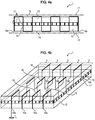
- interlacing is for example illustrated in figures 4a and 4b .
- the interlacing is carried out according to a regular pitch: an irregular or periodic pitch is however also possible.
- the securing element 18 may comprise at least one of the following elements: a textile thread, a metallic thread or even a thread of composite material.
- the material constituting the securing element 18 is chosen so as to withstand the gluing temperatures.
- the securing element 18 therefore has a melting temperature greater than 200 ° C, and preferably greater than 230 ° C.
- the textile yarn can be made from at least one of the following materials: polyester, polyamide, polyketone, polyvinyl alcohol, cellulose, a mineral fiber, a natural fiber, an elastomeric material or a mixture of these materials.
- polyesters mention will be made, for example, of PET (polyethylene terephthalate), PEN (polyethylene naphthalate), PBT (polybutylene terephthalate), PBN (polybutylene naphthalate), PPT (polypropylene terephthalate), PPN (polypropylene naphthalate).
- PET polyethylene terephthalate
- PEN polyethylene naphthalate
- PBT polybutylene terephthalate
- PBN polybutylene naphthalate
- PPT polypropylene terephthalate
- PPN polypropylene naphthalate
- polyamides mention will be made of aliphatic polyamides such as polyamides 4-6, 6, 6-6 (nylon
- the yarn may be an assembly of fibers comprising one or more monofilament or multifilament, textile, metallic and / or composite fibers, twisted together or not.
- the fiber assembly comprises fibers substantially parallel to each other or coiled in a helix.
- the diameter of the wire can be between 2 mm and 0.1 mm.
- the securing element 18 can extend continuously or discontinuously between the transverse edges 10c, 10d, 12c, 12d and / or between the longitudinal edges 10a, 10b, 12a, 12b of the first and second structures 10, 12.
- the securing element 18 could also extend along an axis forming an angle that is neither zero nor equal to 90 ° with the first axis 11.
- the securing element 18 extends over the entire length L (respectively the entire width l) of the first structure 10 (the length L corresponding to the smallest distance between the transverse edges 10c, 10d of the first structure 10 when the first structure 10 is flat or, more simply, to the length L of its longitudinal edges 10a, 10b when the first structure 10 is parallelepiped or rectangular, while the width I corresponding to the smallest distance between the longitudinal edges 10a, 10b of the first structure 10 when the first structure 10 is flat or, more simply, to the width I of its transverse edges 10c, 10d when the first structure 10 is parallelepiped or rectangular).
- the securing element 18 extends over only part of the length L (respectively, of the width l) of the first structure 10, preferably over at least 50% of its length L ( respectively, of the width l).
- the securing element 18 preferably comprises at least two adjacent segments 19a separated by a determined distance 19b.
- the distance 19b can in particular be at most equal to one meter.
- the distance 19b is less than one meter, preferably less than 75 cm.
- the number of segments 19a of the securing element 18 increases when their size decreases.
- the width y (dimension in the plane of the first structure 10 and extending in a direction perpendicular to the longitudinal edges 10a, 10b of the first structure 10) of the securing element 18 can be continuous over the length L (respectively, of the width l) of the first structure 10, or variable.
- a continuous width therein is however easier to achieve industrially.
- the securing element 18 may extend along and adjacent to one of the longitudinal edges 10a, 10b (respectively, transverse edges 10c, 10d) of the first structure 10 or alternatively at a distance from said longitudinal edge 10a , 10b 'respectively, of the transverse edge 10c, 10d).
- the external face (that is to say the face opposite to the space 2 formed between the first and the second structure 10, 12) of the first structure 10 and the second structure 12 can be impregnated with an elastomeric composition.
- a first step S1 an assembly comprising a first structure 10, a second structure 12 and a supporting structure 14 is supplied.
- This assembly is generally produced beforehand in a manner known per se and / or can be supplied in the form of a roll, for example from the companies PILE FABRICS GmbH or GIRMES INTERNATIONAL GmbH.
- the assembly is supplied in the form of a roll, the assembly is unwound and laid flat so that one of the first and second structures 10, 12 is on a support surface. In this position, the first and the second structure 10, 12 are therefore stacked on the support surface, the wire elements of the supporting structure 14 already being interlaced with the first and second wire elements 15, 16.
- a second step S2 the position of the first and of the second structure 10, 12 is adjusted so that the first axis 11 and the second axis 13 become parallel, and where appropriate superimposed.
- their position is also adjusted so that their first transverse edges 10c, 12c and / or their second transverse edges 10d, 12d are superimposed.
- the position of the first and of the second structure 10, 12 is adjusted so that the first axis 11 and the second axis 13 are parallel and superimposed and that their first and their second transverse edges 10c, 10d, 12c, 12d are superimposed.
- steps S1, S2 and S3 can be carried out simultaneously or successively, in which case these steps S1, S2 and S3 can be implemented in a different order without thereby departing from the scope of the invention.
- the first and the second structure 10, 12 can be flat over their entire length L, or as a variant the assembly can only be unrolled in part, the rest of the whole being unrolled progressively during the third step of the S process.
- a fourth step S4 the first and the second structure 10, 12 are fixed together by a securing element 18 by interlacing the securing element 18 with the first and second wire elements 15, 16, in order to prevent movement of the first structure 10 relative to the second structure 12 during handling and use of assembly 1.
- At least one of the first and second ends 18a, 18b of the securing element 18 is left free to slide relative to the first and second wire elements 15, 16, so as to maintain the position of the first structure 10 relative to the second structure 20 by friction during storage and handling of the assembly 1 .
- both the first and the second end 18a, 18b of the securing element are left free to slide relative to the first and second wire elements 15, 16.
- the first and the second structure 10, 12 can be fixed by interlacing a single securing element or, as illustrated in the figures, by several distinct securing elements 18.
- the separate connecting elements 18 can extend parallel to one another or transversely to one another.
- steps S1 to S4 can be carried out directly at the weaver's premises in the loom used for the production of the assembly, in order to guarantee that the first and the second structure 10, 12 are perfectly aligned and to avoid operations of winding and unwinding likely to generate alignment difficulties.
- the external face of the first structure 10 and the second structure 12 can be impregnated with an elastomeric composition, typically rubber, for example by calendering. This impregnation can be carried out after the interlacing S4 of the first and second structure 12 with the securing element 18.
- an elastomeric composition typically rubber
- the assembly 1 can then be handled and in particular wound around a cylinder with a view to its storage before its use. This handling is in particular facilitated by the integral fixing of the first structure 10 with the second structure 12, which prevents any sliding of one of the structures 10, 12 relative to the other 12, 10.
- the assembly 1 thus obtained can in particular be used in the production of a tire 4.
- the assembly 1 is placed on a building drum 5 with a view to producing a tire 4. If necessary, the assembly 1 can be cut beforehand. The assembly 1 will then play the role of carcass in the tire 4.
- annular space 2 delimited radially by an internal face of the first structure 10 and an internal face of the second structure 12 is then formed (see figure 1 ).
- the securing element 18 and at least one of the first 18a and the second end 18a of the securing element 18 slide relative to the first and to the second structure 10, 12, at least one of its ends 18a, 18b not being fixed to the first structure 10 nor the second structure 20, allowing thus the radial spacing of the first structure 10 relative to the second structure 12.
- the annular space 2 can for example be formed by inflation.
- at least one of the first 18a and the second end 18b of the securing element 18 slides relative to the first and second wire elements 15, 16 without causing the breaking element to break. solidarity 18.
- the securing element 18 makes it possible to guarantee the correct positioning of the first structure 10 relative to the second structure 12 until they are placed on the building drum 5.
- the securing element 18 is capable of keeping the first structure 10 aligned with the second structure 12, thanks to the frictional forces between the securing element 18 and the first and second wire elements 15, 16, at their contact zones.
- the tire 4 is then formed by attaching and successively fixing a crown 6 and a tread 7.
- the crown 6 and the tread 7 can be conventional.
Landscapes
- Engineering & Computer Science (AREA)
- Mechanical Engineering (AREA)
- Textile Engineering (AREA)
- Tyre Moulding (AREA)
- Tires In General (AREA)
Description
- L'invention concerne de manière générale le domaine des pneumatiques pour un véhicule, typiquement un véhicule de tourisme, à deux roues, poids lourd, agricole, de génie civil ou un avion ou, plus généralement, pour tout dispositif roulant. Plus précisément, l'invention concerne la mise à plat d'un tel pneumatique. En particulier l'invention a pour objet un assemblage, un procédé de fabrication dudit assemblage et un pneumatique comprenant un assemblage obtenu conformément audit procédé de fabrication.
- Un pneumatique 4 est une structure torique destinée à être montée sur une jante, pressurisée par un gaz de gonflage et écrasée sur un sol sous l'action d'une charge.
- Comme visible sur la
figure 1 qui illustre un exemple de pneumatique 4, un pneumatique 4 présente une surface de roulement, (c'est-à-dire une surface destinée à entrer en contact avec un sol), un plan de roulement (c'est-à-dire un plan normal à l'axe de révolution Y-Y' et qui intersecte la surface de roulement), un axe circonférentiel X-X' (qui correspond à un axe du plan de roulement qui est tangent à la surface de roulement) et un axe radial Z-Z' (qui correspond à un axe transversal à l'axe de révolution Y-Y' du pneumatique 4 et qui intersecte l'axe de révolution Y-Y'). - De manière connue en soi, le pneumatique 4 comprend, de l'axe de révolution Y-Y' vers sa surface de roulement, une carcasse, un sommet agencé radialement à l'extérieur de la carcasse 3 et une bande de roulement 7.
- La carcasse est une structure de révolution comprenant une nappe de carcasse comprenant des éléments de renfort de carcasse. Les éléments de renfort de carcasse sont sensiblement parallèles les uns aux autres selon une direction donnée et forment un angle supérieur ou égal à 65°, de préférence supérieur ou égal à 80° et ici plus préférentiellement sensiblement égal à 90° avec l'axe circonférentiel du pneumatique 4. Les éléments de renfort de carcasse peuvent notamment comprendre des éléments de renfort filaires textiles, par exemple comprenant deux brins de polyester de 144 tex enroulés à 290 tours ensemble.
- Le sommet 6 est une structure de révolution agencée radialement à l'extérieur de la carcasse et comprend deux nappes de travail et une nappe de frettage.
- Chaque nappe de travail comprend des éléments de renfort de travail. Les éléments de renfort de travail sont sensiblement parallèles les uns aux autres selon une direction et forment un angle allant de 15° et 40°, de préférence allant de 20° à 30° avec l'axe circonférentiel du pneumatique 4 et ici égal à 26°. Les éléments de renfort de travail sont croisés d'une nappe de travail par rapport à l'autre. Ils peuvent notamment comprendre des éléments de renfort filaires métalliques, par exemple des câbles de structure 2 x 0.30 mm.
- La nappe de frettage est agencée radialement à l'extérieur des nappes de travail et comprend des éléments de renfort filaires de frettage sensiblement parallèles les uns aux autres formant un angle au plus égal à 10°, de préférence allant de 5° à 10° avec la direction circonférentielle du pneumatique 4 et ici égal à 5°. Les éléments de renfort de frettage peuvent comprendre des éléments de renfort filaires textiles, par exemple comprenant deux brins d'aramide de 167 tex enroulés à 315 tours ensemble.
- La bande de roulement 7 est agencée radialement à l'extérieur du sommet et est destinée à entrer en contact avec un sol. La surface de roulement correspond donc à tout ou partie de la face radialement externe de la bande de roulement.
- La nappe de carcasse, les nappes de travail et la nappe de frettage sont réalisées dans une ou plusieurs compositions polymériques, par exemple des compositions élastomériques comprenant au moins un élastomère, de préférence diénique, par exemple du caoutchouc naturel, dans laquelle sont noyés les éléments de renfort correspondants.
- La bande de roulement 7 est réalisée dans une composition polymérique, par exemple une composition élastomérique comprenant au moins un élastomère, de préférence diénique, par exemple du caoutchouc naturel.
- Afin d'améliorer la mise à plat du pneumatique 4, il a été proposé de remplacer tout ou partie de la carcasse par un assemblage comprenant une première structure formée de premiers éléments filaires, une deuxième structure formée de deuxièmes éléments filaires et une structure porteuse comprenant des éléments filaires porteurs reliant la première structure et la deuxième structure. La première structure et la deuxième structure peuvent être enduites ou imprégnées avec une composition élastomérique, typiquement du caoutchouc, par exemple par calandrage.
- Cet assemblage peut par exemple être formé d'un tissu tridimensionnel ou d'un tricot tridimensionnel. On pourra notamment se référer aux documents
WO2017/103490 etWO 2017/103491 , au nom de la Demanderesse, qui décrivent des exemples d'assemblages et leurs procédés de fabrication. - Un tel assemblage permet d'améliorer significativement la mise à plat de la bande de roulement lorsque le pneumatique 4 est soumis à une charge.
- Toutefois, la Demanderesse s'est aperçue du fait que la mise à plat de la bande de roulement était encore améliorée lorsque la structure supérieure et la structure inférieure de l'assemblage étaient parfaitement alignées dans le pneumatique 4. Or il arrive fréquemment, lors de la manutention de l'assemblage, que l'une des structures glisse par rapport à l'autre, la structure porteuse n'était alors pas tendue et ne pouvant donc empêcher leur mouvement relatif.
- Pour cela, le document
WO2017/103490 enseigne l'utilisation d'un moyen sacrificiel pour fixer la structure supérieure sur la structure inférieure lors de la manutention de l'assemblage. En particulier, le moyen sacrificiel permet de garantir le positionnement correct des deux structures jusqu'à leur pose sur le tambour de confection. Ce moyen sacrificiel est par ailleurs dimensionné de sorte à rompre avant de tendre et de rompre les éléments porteurs lorsque la structure supérieure et la structure inférieure sont écartées l'une de l'autre, par exemple au moment du gonflage du pneumatique. Toutefois, la Demanderesse s'est aperçue du fait qu'il pouvait être difficile de dimensionner correctement le moyen sacrificiel afin de garantir à la fois le maintien en position des structures supérieure et inférieure lors de la manutention et sa rupture au moment du gonflage. Or, lorsque le moyen sacrificiel ne rompt pas lors du gonflage, cela a pour conséquence de ralentir la fabrication de l'assemblage. A contrario, lorsque le moyen sacrificiel rompt pendant la manutention de l'assemblage, la première structure et la deuxième structure se désalignent, détériorant ainsi la mise à plat de la bande de roulement. L'utilisation de moyens sacrificiels ne permet donc pas de garantir l'alignement des structures, sauf à les dimensionner précisément à chaque nouvel assemblage. En outre, les moyens sacrificiels doivent être capables de supporter les températures d'encollage, qui peuvent dépasser 200°C. - Les documents
WO 2017/005713 A1 etWO 2016/116490 A1 décrivent des dispositifs de type pneumatique comprenant une structure porteuse reliée à la fois à une structure de révolution radialement extérieure et à une structure de révolution radialement intérieure du dispositif. - Un objectif de l'invention est de proposer un nouvel assemblage, un procédé de fabrication dudit assemblage ainsi qu'un pneumatique comprenant un assemblage obtenu conformément audit procédé de fabrication qui permettent de s'affranchir des difficultés d'alignement de la première et de la deuxième structure de l'assemblage de manière simple, efficace et peu coûteuse sans pour autant ralentir la fabrication de l'assemblage et du pneumatique, et qui permettent de garantir l'obtention d'un pneumatique dont la mise à plat de la bande de roulement est nettement améliorée.
- Pour cela, l'invention propose un assemblage comprenant :
- une première structure formée de premiers éléments filaires, la première structure présentant un bord longitudinal s'étendant suivant une première direction qui définit un premier axe,
- une deuxième structure formée de deuxièmes éléments filaires, la deuxième structure comprenant un bord longitudinal s'étendant suivant une deuxième direction qui définit un deuxième axe,
- une structure porteuse comprenant des éléments filaires porteurs reliant les premiers éléments filaires de la première structure et les deuxièmes éléments filaires de la deuxième structure.
- L'assemblage comprend en outre au moins un élément de solidarisation filaire entrelacé avec les premiers éléments filaires et les deuxièmes éléments filaires, ledit au moins un élément de solidarisation comprenant une première extrémité et une deuxième extrémité, l'une au moins parmi la première et la deuxième extrémité de l'au moins un élément de solidarisation étant libre de glisser par rapport aux premiers et deuxièmes éléments filaires. De plus, le premier axe et le deuxième axe sont parallèles.
- Certaines caractéristiques préférées mais non limitatives de l'assemblage décrit ci-dessus sont les suivantes, prises individuellement ou en combinaison :
- ledit au moins un élément de solidarisation est agencé de façon à ce que, lorsqu'on écarte la première structure et la deuxième structure l'une de l'autre, l'une au moins parmi la première et la deuxième extrémité de l'au moins un élément de solidarisation glisse par rapport aux premiers et deuxièmes éléments filaires.
- ledit au moins un élément de solidarisation est agencé de façon à ce que, lorsqu'on écarte la première structure et la deuxième structure l'une de l'autre de façon à tendre sans rompre les éléments filaires porteurs, l'une au moins parmi la première et la deuxième extrémité de l'au moins un élément de solidarisation glisse par rapport aux premiers et deuxièmes éléments filaires sans entrainer de rupture de l'au moins un élément de solidarisation.
- le premier axe et le deuxième axe sont superposés.
- la première structure et la deuxième structure comprennent chacune un bord transversal s'étendant perpendiculairement à leur bord longitudinal respectif, et dans lequel le bord transversal de la première structure et le bord transversal de la deuxième structure sont superposés.
- la première et la deuxième extrémité de l'au moins un élément de solidarisation sont libres de glisser par rapport aux premiers et deuxièmes éléments filaires.
- la première structure présente deux bords transversaux opposés s'étendant transversalement à son bord longitudinal, une longueur de la première structure étant égale à une plus courte distance entre ses bords transversaux lorsque la première structure est à plat, et dans lequel l'au moins un élément de solidarisation s'étend sur tout ou partie de la longueur de la première structure.
- l'au moins un élément de solidarisation s'étend sur au moins 50% de la longueur de la première structure.
- l'au moins un élément de solidarisation s'étend suivant une troisième direction qui définit un troisième axe, un angle entre le troisième axe et le premier axe étant non nul.
- l'au moins un élément de solidarisation comprend l'un au moins des éléments suivants : un fil textile, un fil métallique, un fil en matériau composite. Et/ou
- l'assemblage comprend au moins deux éléments de solidarisation distincts.
- Selon un deuxième aspect, l'invention propose également un procédé de fabrication d'un assemblage tel que décrit ci-dessus, ledit procédé de fabrication comprenant les étapes suivantes :
- placer la première structure sur la deuxième structure de sorte que le premier axe et le deuxième axe sont sensiblement parallèles, et
- fixer la première structure sur la deuxième structure en entrelaçant au moins un élément de solidarisation avec les premiers éléments filaires et les deuxièmes éléments filaires de sorte à maintenir la première structure en position par rapport à la deuxième structure, l'une au moins parmi la première et la deuxième extrémité de l'au moins un élément de solidarisation étant laissée libre de glisser par rapport aux premiers et deuxièmes éléments filaires.
- Certaines caractéristiques préférées mais non limitatives du procédé de fabrication décrit ci-dessus sont les suivantes, prises individuellement ou en combinaison :
- le procédé de fabrication comprend, postérieurement à l'étape de fixation, une étape d'écartement de la première structure et la deuxième structure l'une de l'autre durant laquelle l'une au moins parmi la première et la deuxième extrémité de l'au moins un élément de solidarisation glisse par rapport aux premiers et deuxièmes éléments filaires.
- durant l'étape d'écartement, l'une au moins parmi la première et la deuxième extrémité de l'au moins un élément de solidarisation glisse par rapport aux premiers et deuxièmes éléments filaires sans entrainer de rupture de l'au moins un élément de solidarisation.
- le procédé de fabrication comprend en outre, préalablement à l'étape de fixation, une étape au cours de laquelle le premier axe et le deuxième axe sont superposés.
- la première structure et la deuxième structure comprennent chacune un bord transversal s'étendant transversalement à leur bord longitudinal respectif, le procédé de fabrication comprenant en outre, préalablement à l'étape de fixation, une étape au cours de laquelle le bord transversal de la première structure et le bord transversal de la deuxième structure sont superposés.
- la première structure présente deux bords transversaux opposés s'étendant transversalement à son bord longitudinal, une longueur de la première structure étant égale à une plus courte distance entre ses bords transversaux lorsque la première structure est à plat, la première structure étant fixée sur tout ou partie de sa longueur sur la deuxième structure.
- l'au moins un élément de solidarisation fixe la première structure sur la deuxième structure sur au moins 50% de sa longueur.
- deux éléments de solidarisation sont entrelacés avec les premiers éléments filaires et les deuxièmes éléments filaires en deux zones distinctes de l'assemblage.
- Selon un troisième aspect, l'invention propose un pneumatique présentant un axe de révolution et comprenant :
- un assemblage obtenu conformément à un procédé de réalisation décrit ci-dessus, et
- un espace annulaire délimité radialement par une face interne de la première structure et par une face interne de la deuxième structure.
- D'autres buts et avantages de la présente invention apparaîtront mieux à la lecture de la description détaillée qui va suivre, et au regard des dessins annexés donnés à titre d'exemples non limitatifs et sur lesquels :
- La
figure 1 est une vue en perspective et en coupe partielle d'un exemple de réalisation d'un pneumatique selon un mode de réalisation de l'invention représenté en l'absence de charge appliquée et de pression. - La
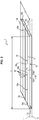
figure 2 est une vue en perspective d'un exemple de réalisation d'un assemblage conforme à un mode de réalisation de l'invention, sur laquelle la structure porteuse de l'assemblage a été omise. - La
figure 3 est un organigramme illustrant des étapes d'un procédé de fabrication d'un assemblage conforme à un mode de réalisation de l'invention. - Les
figures 4a et 4b illustrent respectivement une vue en coupe le long d'un élément de solidarisation et une vue en perspective d'un exemple de réalisation d'un assemblage conforme à l'invention. - L'assemblage 1 comprend :
- une première structure 10 formée de premiers éléments filaires 15,
- une deuxième structure 12 formée de deuxièmes éléments filaires 16, et
- une structure porteuse 14 comprenant des éléments filaires porteurs 17 reliant la première structure 10 et la deuxième structure 12.
- Des exemples d'assemblages 1 comprenant ces trois structures 10, 12, 14 et pouvant être utilisés ont par exemple été décrits en détails dans les documents
WO2017/103490 etWO 2017/103491 décrits ci-avant. - Plus précisément, la première structure 10 est globalement trapézoïdale (par exemple parallélépipédique ou rectangulaire) et présente un premier bord longitudinal 10a s'étendant suivant une première direction qui définit un premier axe 11, un deuxième bord longitudinal 10b opposé au premier bord longitudinal 10a et deux bords transversaux opposés 10c, 10d, s'étendant transversalement aux premier et deuxième bords longitudinaux 10a, 10b.
- De même, la deuxième structure 12 est globalement trapézoïdale (par exemple parallélépipédique ou rectangulaire) et présente un premier bord longitudinal 12a s'étendant suivant une deuxième direction qui définit un deuxième axe 13, un deuxième bord longitudinal 12b opposé au premier bord longitudinal 12a et deux bords transversaux 12c, 12d opposés, s'étendant transversalement aux premier et deuxième bords longitudinaux 12a, 12b.
- Dans un mode de réalisation, la première et la deuxième structure 10, 12 peuvent comprendre un tissu formé d'un entrecroisement de fils de chaine (les premiers et deuxièmes éléments filaires 15, 16) et de fils de trame. L'assemblage 1 est alors un tissu tridimensionnel.
- En variante, la première et la deuxième structure 10, 12 peuvent comprendre un tricot, auquel cas l'assemblage 1 est un tricot tridimensionnel.
- Quelle que soit la variante de réalisation, l'armature du tissu de la première et/ou de la deuxième structure 12 peut être de type toile, serge, tricot ou satin. Dans le cas d'un assemblage 1 pour un pneumatique 4, une armure de type toile permet d'atteindre de bonnes performances mécaniques.
- Selon une autre variante encore, l'une parmi la première et la deuxième structure 10, 12 comprend un tissu, l'autre parmi la première et la deuxième structure 10, 12 pouvant comprendre un tricot.
- Typiquement, l'assemblage 1 peut comprendre un tissu ou un tricot tridimensionnel du type armure toile simple ou double paroi, tel que par exemple : le tissu double paroi PF-Farbroller-GR3-7103_01 commercialisé par la société PILE FABRICS GmbH ; le tricot N-02570-A01 commercialisé par la société HEATHCOAT FABRICS Limited.
- L'assemblage 1 comprend en outre au moins un élément de solidarisation 18 filaire entrelacé avec les premiers éléments filaires 15 et les deuxièmes éléments filaires 16 afin de maintenir la première structure 10 en position par rapport à la deuxième structure 12 de sorte que le premier axe 11 et le deuxième axe 13 soient parallèles. Par ailleurs, l'élément de solidarisation 18 comprend une première extrémité 18a et une deuxième extrémité 18b, et l'une au moins parmi la première 18a et la deuxième extrémité 18b de l'élément de solidarisation 18 est libre de glisser par rapport aux premiers et deuxièmes éléments filaires 15, 16.
- On notera en particulier que l'élément de solidarisation 18 permet ainsi de garantir le positionnement correct de la première structure 10 par rapport à la deuxième structure 12 grâce aux forces de frottement entre l'élément de solidarisation 18 et les premiers et deuxièmes éléments filaires 15, 16, au niveau de leurs zones de contact.
- En particulier et aux fins du procédé de fabrication décrit ci-dessous, l'élément de solidarisation 18 est agencé de façon à ce que, lorsqu'on écarte la première structure 10 et la deuxième structure 12 l'une de l'autre, l'une au moins parmi la première 18a et la deuxième extrémité 18b de l'élément de solidarisation 18 glisse par rapport aux premiers et deuxièmes éléments filaires 15, 16. On notera également que contrairement à l'assemblage décrit dans
WO2017/103490 , l'élément de solidarisation 18 est ici agencé de façon à ce que, lorsqu'on écarte la première structure 10 et la deuxième structure 12 l'une de l'autre de façon à tendre sans rompre les éléments filaires porteurs 17, l'une au moins parmi la première 18a et la deuxième extrémité 18b de l'élément de solidarisation 18 glisse par rapport aux premiers et deuxièmes éléments filaires 15, 16 sans entrainer de rupture de l'au moins un élément de solidarisation 18. - De préférence, le premier axe 11 et le deuxième axe 13 sont en outre superposés et/ou les premiers et deuxièmes bords transversaux 10a, 12a, 10b, 12b de la première et de la deuxième structure 12, respectivement, sont superposés. Par superposés, on comprendra ici que le premier axe 11 et le deuxième axe 13 (respectivement les premiers et deuxième bords transversaux 10a, 12a, 10b, 12b) appartiennent à un plan déterminé qui correspond au plan passant par le premier axe 11 (respectivement le premier bord transversal 10a ou le deuxième bord transversal 10b) et qui est perpendiculaire à la surface de la première structure 10 lorsque la première structure 10 est posée à plat sur une surface plane.
- La tolérance d'alignement du premier axe 11 et du deuxième axe 13 et la tolérance de superposition des bords (longitudinaux 10a, 12a, 10b, 12b et/ou transversaux 10c, 12c, 10d, 12d) est inférieure ou égale à deux millimètres, de préférence inférieure ou égale à un millimètre.
- Dans une forme de réalisation, à la fois le premier axe 11 et le deuxième axe 13 d'une part et les bords transversaux 10c, 10d, 12c, 12d de la première 10 et de la deuxième structure 12 d'autre part sont superposés, de sorte que la première et la deuxième structure 10, 12 sont parfaitement superposées et alignées (avec une tolérance inférieure ou égale à deux millimètres, de préférence inférieure ou égale à un millimètre). Grâce à l'entrelacement de l'élément de solidarisation 18 avec les premiers éléments filaires 15 et les deuxièmes éléments filaires 16, l'alignement est assuré pendant l'intégralité de la manutention de l'assemblage 1 jusqu'à au moins sa première pose sur un tambour de confection 5 de pneumatique 4.
- Un exemple d'entrelacement est par exemple illustré en
figures 4a et 4b . Dans cet exemple, l'entrelacement est réalisé suivant un pas régulier : un pas irrégulier ou périodique est cependant également envisageable. - L'élément de solidarisation 18 peut comprendre l'un au moins des éléments suivants : un fil textile, un fil métallique ou encore un fil en matériau composite. Le matériau constitutif de l'élément de solidarisation 18 est choisi de sorte à supporter les températures d'encollage. De préférence, l'élément de solidarisation 18 présente donc une température de fusion supérieure à 200°C, et de préférence supérieure à 230°C.
- Par exemple, le fil textile peut être réalisé dans l'un au moins des matériaux suivants : du polyester, du polyamide, du polycétone, de l'alcool polyvinylique, de la cellulose, une fibre minérale, une fibre naturelle, un matériau élastomérique ou un mélange de ces matériaux. Parmi les polyesters on citera par exemple les PET (polyéthylène téréphthalate), PEN (polyéthylène naphthalate), PBT (polybutylène téréphthalate), PBN (polybutylène naphthalate), PPT (polypropylène téréphthalate), PPN (polypropylène naphthalate). Parmi les polyamides, on citera les polyamides aliphatiques tels que les polyamides 4-6, 6, 6-6 (nylon) et les polyamides aromatiques tels que l'aramide.
- Dans un exemple de réalisation, le fil peut être un assemblage de fibres comprenant une ou plusieurs fibres mono-filamentaire ou multi-filamentaires, textiles, métalliques et/ou composites, retordues ensemble ou non. Ainsi, dans un mode de réalisation, l'assemblage de fibres comprendre des fibres sensiblement parallèles les unes aux autres ou enroulées en hélice.
- Le diamètre du fil peut être compris entre 2 mm et 0,1 mm.
- L'élément de solidarisation 18 peut s'étendre de manière continue ou discontinue entre les bords transversaux 10c, 10d, 12c, 12d et/ou entre les bords longitudinaux 10a, 10b, 12a, 12b des première et deuxième structures 10, 12. En variante, l'élément de solidarisation 18 pourrait également s'étendre suivant un axe formant un angle non nul ni égal à 90° avec le premier axe 11.
- Par continue, on comprendra ici que l'élément de solidarisation 18 s'étend sur toute la longueur L (respectivement toute la largeur l) de la première structure 10 (la longueur L correspondant à la plus petite distance entre les bords transversaux 10c, 10d de la première structure 10 lorsque la première structure 10 est à plat ou, plus simplement, à la longueur L de ses bords longitudinaux 10a, 10b lorsque la première structure 10 est parallélépipédique ou rectangulaire, tandis que la largeur I correspondant à la plus petite distance entre les bords longitudinaux 10a, 10b de la première structure 10 lorsque la première structure 10 est à plat ou, plus simplement, à la largeur I de ses bords transversaux 10c, 10d lorsque la première structure 10 est parallélépipédique ou rectangulaire).
- Par discontinue, on comprendra ici que l'élément de solidarisation 18 s'étend sur une partie seulement de la longueur L (respectivement, de la largeur l) de la première structure 10, de préférence sur au moins 50% de sa longueur L (respectivement, de la largeur l). Dans ce cas, comme illustré sur la
figure 2 , l'élément de solidarisation 18 comprend de préférence au moins deux segments 19a adjacents séparés d'une distance 19b déterminée. Afin de garantir que la première structure 10 et la deuxième structure restent parfaitement alignées et superposées en tout point de l'assemblage 1, même lors de la manutention de l'assemblage 1, la distance 19b peut notamment être au plus égale à un mètre. Dans un mode de réalisation, la distance 19b est inférieure à un mètre, de préférence inférieure à 75 cm. Afin de couvrir au moins 50% de la longueur L de la première structure 10, on comprendra que le nombre de segments 19a de l'élément de solidarisation 18 augmente lorsque leur dimension diminue. - La largeur y (dimension dans le plan de la première structure 10 et s'étendant suivant une direction perpendiculaire aux bords longitudinaux 10a, 10b de la première structure 10) de l'élément de solidarisation 18 peut être continue sur la longueur L (respectivement, de la largeur l) de la première structure 10, ou variable. Une largeur y continue est cependant plus aisée à réaliser industriellement.
- L'élément de solidarisation 18 peut s'étendre le long et de manière adjacente à l'un des bords longitudinaux 10a, 10b (respectivement, des bords transversaux 10c, 10d) de la première structure 10 ou en variante à distance dudit bord longitudinal 10a, 10b 'respectivement, du bord transversal 10c, 10d).
- De manière optionnelle, la face externe (c'est-à-dire la face opposée à l'espace 2 formé entre la première et la deuxième structure 10, 12) de la première structure 10 et la deuxième structure 12 peut être imprégnée d'une composition élastomérique.
- Un exemple de fabrication S d'un tel assemblage 1 va à présent être décrit.
- Au cours d'une première étape S1, un ensemble comprenant une première structure 10, une deuxième structure 12 et une structure porteuse 14 est amené. Cet ensemble est généralement réalisé préalablement de manière connue en soi et/ou peut être fourni sous forme de rouleau, par exemple auprès des sociétés PILE FABRICS GmbH ou GIRMES INTERNATIONAL GmbH.
- Dans le cas où l'ensemble est fourni sous la forme d'un rouleau, l'ensemble est déroulé et placé à plat de sorte que l'une parmi la première et la deuxième structure 10, 12 se trouve sur une surface support. Dans cette position, la première et la deuxième structure 10, 12 sont donc empilées sur la surface support, les éléments filaires de la structure porteuse 14 étant déjà entrelacés avec les premiers et deuxièmes éléments filaires 15, 16.
- Au cours d'une deuxième étape S2, la position de la première et de la deuxième structure 10, 12 est ajustée de sorte que le premier axe 11 et le deuxième axe 13 deviennent parallèles, et le cas échéant superposés. De manière optionnelle, au cours d'une troisième étape S3, leur position est également ajustée de sorte que leurs premiers bords transversaux 10c, 12c et/ou leurs deuxièmes bords transversaux 10d, 12d soient superposés.
- De préférence, la position de la première et de la deuxième structure 10, 12 est ajustée de sorte que le premier axe 11 et le deuxième axe 13 soient parallèle et superposés et que leur premier et leur deuxième bord transversal 10c, 10d, 12c, 12d soient superposés. On comprendra bien entendu que les étapes S1, S2 et S3 peuvent être réalisées simultanément ou successivement, auquel cas ces étapes S1, S2 et S3 peuvent être sont mises en œuvre dans un ordre différent sans sortir pour autant de la portée de l'invention.
- Lors de ces étapes S1, S2 et/ou S3, la première et la deuxième structure 10, 12 peuvent être à plat sur toute leur longueur L, ou en variante l'ensemble peut n'être déroulé qu'en partie, le reste de l'ensemble étant déroulé au fur et à mesure pendant la troisième étape du procédé S.
- Au cours d'une quatrième étape S4, la première et la deuxième structure 10, 12 sont fixées ensemble par un élément de solidarisation 18 en entrelaçant l'élément de solidarisation 18 avec les premiers et les deuxièmes éléments filaires 15, 16, afin d'empêcher le mouvement de la première structure 10 par rapport à la deuxième structure 12 lors de la manutention et de l'utilisation de l'assemblage 1. L'une au moins parmi la première et la deuxième extrémité18a, 18b de l'élément de solidarisation 18 est laissée libre de glisser par rapport aux premiers et deuxièmes éléments filaires 15, 16, de sorte à maintenir la position de la première structure 10 par rapport à la deuxième structure 20 par frottement lors du stockage et de la manutention de l'assemblage 1.
- Dans une forme de réalisation à la fois la première et la deuxième extrémité 18a, 18b de l'élément de solidarisation sont laissées libres de glisser par rapport aux premiers et deuxièmes éléments filaires 15, 16.
- Lorsque l'une des extrémités 18a, 18b de l'élément de solidarisation 18 est fixée sur la première structure 10 ou la deuxième structure, sa fixation peut être réalisée par couture, par collage ou par soudure à ultrasons.
- La première et la deuxième structure 10, 12 peuvent être fixées par entrelacement d'un unique élément de solidarisation ou, comme illustré sur les figures, par plusieurs éléments de solidarisation 18 distincts. Dans ce cas, les éléments de solidarisation 18 distincts peuvent s'étendre parallèlement les uns aux autres ou transversalement les uns aux autres.
- En variante, les étapes S1 à S4 peuvent être réalisées directement chez le tisseur dans le métier à tisser utilisé pour la réalisation de l'ensemble, afin de garantir que la première et la deuxième structure 10, 12 sont parfaitement alignées et éviter des opérations d'enroulage et de déroulage susceptibles de générer des difficultés d'alignement.
- De manière optionnelle, la face externe de la première structure 10 et la deuxième structure 12 peuvent être imprégnées d'une composition élastomérique, typiquement du caoutchouc, par exemple par calandrage. Cette imprégnation peut être réalisée après l'entrelacement S4 des première et deuxième structure 12 avec l'élément de solidarisation 18.
- Le cas échéant, l'assemblage 1 peut ensuite être manutentionné et notamment enroulé autour d'un cylindre en vue de son stockage avant son utilisation. Cette manutention est notamment facilitée par la fixation solidaire de la première structure 10 avec la deuxième structure 12, qui évite tout glissement de l'une des structures 10, 12 par rapport à l'autre 12, 10.
- L'assemblage 1 ainsi obtenu peut notamment être utilisé dans la réalisation d'un pneumatique 4.
- Pour cela, l'assemblage 1 est placé sur un tambour de confection 5 en vue de réaliser un pneumatique 4. Le cas échéant, l'assemblage 1 peut être préalablement découpé. L'assemblage 1 jouera alors le rôle de carcasse dans le pneumatique 4.
- Un espace annulaire 2 délimité radialement par une face interne de la première structure 10 et une face interne de la deuxième structure 12 est ensuite formé (voir
figure 1 ). Au cours de la formation de cet espace durant laquelle on écarte la première structure 10 et la deuxième structure 12 l'une de l'autre, l'élément de solidarisation 18 et l'une au moins parmi la première 18a et la deuxième extrémité 18a de l'élément de solidarisation 18 glissent par rapport à la première et à la deuxième structure 10, 12, l'une au moins de ses extrémités 18a, 18b n'étant pas fixée sur la première structure 10 ni la deuxième structure 20, permettant ainsi l'écartement radial de la première structure 10 par rapport à la deuxième structure 12. L'espace annulaire 2 peut par exemple être formé par gonflage. Durant l'étape d'écartement, l'une au moins parmi la première 18a et la deuxième extrémité 18b de l'élément de solidarisation 18 glisse par rapport aux premiers et deuxièmes éléments filaires 15, 16 sans entrainer de rupture de l'élément de solidarisation 18. - On notera en particulier que l'élément de solidarisation 18 permet de garantir le positionnement correct de la première structure 10 par rapport à la deuxième structure 12 jusqu'à leur pose sur le tambour de confection 5. En effet, l'élément de solidarisation 18 est capable de maintenir la première structure 10 alignée avec la deuxième structure 12, grâce aux forces de frottement entre l'élément de solidarisation 18 et les premiers et deuxièmes éléments filaires 15, 16, au niveau de leurs zones de contact. Le pneumatique 4 est alors formé en rapportant et en fixant successivement un sommet 6 et une bande de roulement 7. Le sommet 6 et la bande de roulement 7 peuvent être conventionnels.
- On pourra notamment se référer aux documents
WO2017/103490 etWO 2017/103491 décrits ci-avant pour plus de détails sur des moyens de fabrication d'un pneumatique 4 avec un tel assemblage 1.
Claims (15)
- Assemblage (1) comprenant :- une première structure (10) formée de premiers éléments filaires (15), la première structure (10) présentant un bord longitudinal (10a, 10b) s'étendant suivant une première direction qui définit un premier axe (11),- une deuxième structure (12) formée de deuxièmes éléments filaires (16), la deuxième structure (12) comprenant un bord longitudinal (12a, 12b) s'étendant suivant une deuxième direction qui définit un deuxième axe (13),- une structure porteuse (14) comprenant des éléments filaires porteurs (17) reliant les premiers éléments filaires (15) de la première structure (10) et les deuxièmes éléments filaires (16) de la deuxième structure (12),l'assemblage (1) comprenant en outre au moins un élément de solidarisation (18) filaire entrelacé avec les premiers éléments filaires (15) et les deuxièmes éléments filaires (16), ledit au moins un élément de solidarisation (18) comprenant une première extrémité (18a) et une deuxième extrémité (18b), le premier axe (11) et le deuxième axe 13) étant parallèles, l'assemblage (1) étant caractérisé en ce que l'une au moins parmi la première et la deuxième extrémité (18a, 18b) de l'au moins un élément de solidarisation (18) est libre de glisser par rapport aux premiers et deuxièmes éléments filaires (15, 16).
- Assemblage (1) selon la revendication 1, dans lequel ledit au moins un élément de solidarisation (18) est agencé de façon à ce que, lorsqu'on écarte la première structure (10) et la deuxième structure (12) l'une de l'autre, l'une au moins parmi la première (18a) et la deuxième extrémité (18b) de l'au moins un élément de solidarisation (18) glisse par rapport aux premiers et deuxièmes éléments filaires (15, 16).
- Assemblage (1) selon l'une des revendications 1 ou 2, dans lequel ledit au moins un élément de solidarisation (18) est agencé de façon à ce que, lorsqu'on écarte la première structure (10) et la deuxième structure (12) l'une de l'autre de façon à tendre sans rompre les éléments filaires porteurs (17), l'une au moins parmi la première (18a) et la deuxième extrémité (18b) de l'au moins un élément de solidarisation (18) glisse par rapport aux premiers et deuxièmes éléments filaires (15, 16) sans entrainer de rupture de l'au moins un élément de solidarisation (18).
- Assemblage (1) selon l'une des revendications 1 à 3, dans lequel le premier axe (11) et le deuxième axe (13) sont superposés.
- Assemblage (1) selon l'une des revendications 1 à 4, dans lequel la première structure (10) et la deuxième structure (12) comprennent chacune un bord transversal (10c, 12c; 10d, 12d) s'étendant perpendiculairement à leur bord longitudinal (10a, 10b ; 12a, 12b) respectif, et dans lequel le bord transversal (10c, 10d) de la première structure (10) et le bord transversal (12c, 12d) de la deuxième structure (12) sont superposés.
- Assemblage (1) selon l'une des revendications 1 à 5, dans lequel la première et la deuxième extrémité (18a, 18b) de l'au moins un élément de solidarisation (18) sont libres de glisser par rapport aux premiers et deuxièmes éléments filaires (15, 16).
- Assemblage (1) selon l'une des revendications 1 à 6, dans lequel la première structure (10) présente deux bords transversaux (10c, 10d) opposés s'étendant transversalement à son bord longitudinal (10a, 10b), une longueur (L) de la première structure (10) étant égale à une plus courte distance entre ses bords transversaux (10c, 10d) lorsque la première structure (10) est à plat, et dans lequel l'au moins un élément de solidarisation (18) s'étend sur tout ou partie de la longueur (L) de la première structure (10).
- Assemblage (1) selon l'une des revendications 1 à 7, dans lequel l'au moins un élément de solidarisation (18) s'étend suivant une troisième direction qui définit un troisième axe, un angle entre le troisième axe et le premier axe (11) étant non nul.
- Procédé de fabrication (S) d'un assemblage (1) selon l'une des revendications 1 à 8, ledit procédé de fabrication (S) comprenant les étapes suivantes :- placer (S1) la première structure (10) sur la deuxième structure (12) de sorte que le premier axe (11) et le deuxième axe (13) sont sensiblement parallèles, et- fixer (S4) la première structure (10) sur la deuxième structure (12) en entrelaçant au moins un élément de solidarisation (18) avec les premiers éléments filaires (15) et les deuxièmes éléments filaires (16) de sorte à maintenir la première structure (10) en position par rapport à la deuxième structure (12), l'une au moins parmi la première et la deuxième extrémité (18a, 18b) de l'au moins un élément de solidarisation (18) étant laissée libre de glisser par rapport aux premiers et deuxièmes éléments filaires (15, 16).
- Procédé de fabrication (S) selon la revendication précédente, comprenant, postérieurement à l'étape de fixation (S4), une étape d'écartement de la première structure (10) et la deuxième structure (12) l'une de l'autre durant laquelle l'une au moins parmi la première (18a) et la deuxième extrémité (18a) de l'au moins un élément de solidarisation (18) glisse par rapport aux premiers et deuxièmes éléments filaires (15, 16).
- Procédé de fabrication (S) selon la revendication précédente, dans lequel durant l'étape d'écartement, l'une au moins parmi la première (18a) et la deuxième extrémité (18b) de l'au moins un élément de solidarisation (18) glisse par rapport aux premiers et deuxièmes éléments filaires (15, 16) sans entrainer de rupture de l'au moins un élément de solidarisation (18).
- Procédé de fabrication (S) selon l'une des revendications 9 à 11, comprenant en outre, préalablement à l'étape de fixation (S4), une étape (S2) au cours de laquelle le premier axe (11) et le deuxième axe (13) sont superposés.
- Procédé de fabrication (S) selon l'une des revendications 9 à 12, dans lequel la première structure (10) et la deuxième structure (12) comprennent chacune un bord transversal (10c, 12c ; 10d, 12d) s'étendant transversalement à leur bord longitudinal (10a, 10b ; 12a, 12b) respectif, le procédé de fabrication (S) comprenant en outre, préalablement à l'étape de fixation (S4), une étape (S3) au cours de laquelle le bord transversal (10c, 10d) de la première structure (10) et le bord transversal (12c, 12d) de la deuxième structure (12) sont superposés.
- Procédé de fabrication (S) selon l'une des revendications 9 à 13, dans lequel la première structure (10) présente deux bords transversaux (10c, 10d) opposés s'étendant transversalement à son bord longitudinal (10a, 10b), une longueur (L) de la première structure (10) étant égale à une plus courte distance entre ses bords transversaux (10c, 10d) lorsque la première structure (10) est à plat, la première structure (10) étant fixée (S4) sur tout ou partie de sa longueur (L) sur la deuxième structure (12).
- Pneumatique (4) présentant un axe de révolution (Y-Y') et comprenant :- un assemblage (1) obtenu conformément à un procédé de fabrication (S) selon l'une des revendications 9 à 14, et- un espace annulaire (2) délimité radialement par une face interne de la première structure (10) et par une face interne de la deuxième structure (12).
Applications Claiming Priority (2)
| Application Number | Priority Date | Filing Date | Title |
|---|---|---|---|
| FR1759772 | 2017-10-18 | ||
| PCT/FR2018/052602 WO2019077280A1 (fr) | 2017-10-18 | 2018-10-18 | Assemblage |
Publications (2)
| Publication Number | Publication Date |
|---|---|
| EP3697629A1 EP3697629A1 (fr) | 2020-08-26 |
| EP3697629B1 true EP3697629B1 (fr) | 2021-12-01 |
Family
ID=60382435
Family Applications (1)
| Application Number | Title | Priority Date | Filing Date |
|---|---|---|---|
| EP18800700.9A Active EP3697629B1 (fr) | 2017-10-18 | 2018-10-18 | Assemblage |
Country Status (4)
| Country | Link |
|---|---|
| US (1) | US12427808B2 (fr) |
| EP (1) | EP3697629B1 (fr) |
| CN (1) | CN111225806B (fr) |
| WO (1) | WO2019077280A1 (fr) |
Families Citing this family (4)
| Publication number | Priority date | Publication date | Assignee | Title |
|---|---|---|---|---|
| FR3090498A3 (fr) | 2018-12-24 | 2020-06-26 | Michelin & Cie | Assemblage pour un pneumatique, pneumatique et procédés de fabrication associés |
| FR3090497B3 (fr) | 2018-12-24 | 2020-12-04 | Michelin & Cie | Assemblage pour un pneumatique, pneumatique et procédés de fabrication associés |
| WO2022235697A1 (fr) * | 2021-05-03 | 2022-11-10 | The Carlstar Group Llc | Pneu non pneumatique à renforcements de réglage de tension à angles multiples |
| FR3124526B1 (fr) | 2021-06-24 | 2023-06-30 | Michelin & Cie | Panneau conformable comprenant deux faces reliées par une structure de liaison uniforme |
Family Cites Families (22)
| Publication number | Priority date | Publication date | Assignee | Title |
|---|---|---|---|---|
| US3424220A (en) * | 1965-10-21 | 1969-01-28 | Astro Research Corp | Isotensoid structures and method |
| IT978891B (it) * | 1973-02-07 | 1974-09-20 | Mecmor Spa | Dispositivo per ottenere maglie regolari alle estremita di tes suti a maglia in lavorazione su macchine per maglieria |
| US4336296A (en) * | 1978-12-27 | 1982-06-22 | Agency Of Industrial Science & Technology | Three-dimensionally latticed flexible-structure composite |
| GB2134049A (en) * | 1983-01-21 | 1984-08-08 | Bell Graham | Model vehicle tyre |
| US4945962A (en) * | 1989-06-09 | 1990-08-07 | The Uniroyal Goodrich Tire Company | Honeycomb non-pneumatic tire with a single web on one side |
| DE29521299U1 (de) * | 1995-09-28 | 1997-01-09 | ContiTech Formteile GmbH, 30453 Hannover | Rad für Ofenwagen u.dgl. |
| US6142205A (en) * | 1998-03-13 | 2000-11-07 | The Goodyear Tire & Rubber Company | Tire with composite ply structure |
| US6733862B2 (en) * | 2000-12-27 | 2004-05-11 | Albany International Techniweave, Inc. | Reinforced article and method of making |
| CA2412644A1 (fr) * | 2001-04-16 | 2002-10-24 | Michelin Recherche Et Technique S.A. | Pneumatique souple a support structurel muni d'une carcasse diagonale |
| JP4004471B2 (ja) * | 2001-10-31 | 2007-11-07 | 旭化成せんい株式会社 | 多層構造を有する弾性編地及びその製造方法 |
| DE102005010540A1 (de) * | 2005-03-04 | 2006-09-07 | Mattes & Ammann Kg | Stromleitfähiges Gewirk oder Gestrick für Heizzwecke, seine Verwendung und Wirk- oder Strickmaschine |
| JP2011122263A (ja) * | 2009-12-10 | 2011-06-23 | Tsudakoma Corp | ゴム補強用織物製織用織機におけるタックイン耳形成装置 |
| CN103287025B (zh) * | 2012-02-28 | 2015-12-02 | 香港纺织及成衣研发中心有限公司 | 一种三维负泊松比间隔针织物及其制作方法 |
| US8931531B2 (en) * | 2012-05-18 | 2015-01-13 | The Goodyear Tire & Rubber Company | System for non-pneumatic support of a vehicle |
| KR101495474B1 (ko) * | 2014-03-07 | 2015-02-23 | 전남대학교산학협력단 | 유연성 선상체를 이용한 3차원 격자 트러스 구조체의 제조방법 |
| US9849734B2 (en) * | 2014-10-31 | 2017-12-26 | The Goodyear Tire & Rubber Company | Pneumatic tire with a three dimensional component |
| FR3031932B1 (fr) * | 2015-01-22 | 2017-02-03 | Michelin & Cie | Dispositif de type pneumatique pour vehicule |
| FR3038543B1 (fr) * | 2015-07-06 | 2017-07-21 | Michelin & Cie | Dispositif de type pneumatique pour vehicule |
| FR3045462B1 (fr) * | 2015-12-17 | 2017-12-29 | Michelin & Cie | Ensemble pour pneumatique comprenant des tissu(s) ou tricot(s) impregnes et un moyen de maintien sacrificiel |
| FR3045463B1 (fr) | 2015-12-17 | 2017-12-29 | Michelin & Cie | Assemblage pour pneumatique comprenant des tissu(s) ou tricot(s) comprenant des elements filaires pre-encolles |
| JP2017190127A (ja) * | 2016-04-13 | 2017-10-19 | ザ・グッドイヤー・タイヤ・アンド・ラバー・カンパニー | 剪断バンド及び非空気式タイヤ |
| CN205836390U (zh) * | 2016-07-28 | 2016-12-28 | 虞晓新 | 一种免充气轮胎 |
-
2018
- 2018-10-18 WO PCT/FR2018/052602 patent/WO2019077280A1/fr not_active Ceased
- 2018-10-18 EP EP18800700.9A patent/EP3697629B1/fr active Active
- 2018-10-18 CN CN201880067525.3A patent/CN111225806B/zh active Active
- 2018-10-18 US US16/757,074 patent/US12427808B2/en active Active
Also Published As
| Publication number | Publication date |
|---|---|
| WO2019077280A1 (fr) | 2019-04-25 |
| US20200254819A1 (en) | 2020-08-13 |
| US12427808B2 (en) | 2025-09-30 |
| CN111225806B (zh) | 2022-06-24 |
| EP3697629A1 (fr) | 2020-08-26 |
| CN111225806A (zh) | 2020-06-02 |
Similar Documents
| Publication | Publication Date | Title |
|---|---|---|
| EP3568291B1 (fr) | Assemblage pour pneumatique comprenant une structure rompable et une structure porteuse, pneumatique et procédé de fabrication dudit pneu | |
| EP3568290B1 (fr) | Assemblage comprenant un tissu partiellement rompable et une structure porteuse | |
| EP3568289B1 (fr) | Assemblage comprenant une structure élastique et une structure porteuse | |
| EP3390114B1 (fr) | Ensemble pour pneumatique comprenant des tissu(s) ou tricot(s) imprégnés et un moyen de maintien sacrificiel | |
| EP3697629B1 (fr) | Assemblage | |
| EP3902692B1 (fr) | Assemblage pour un pneumatique, pneumatique et procédés de fabrication associés | |
| EP3697606B1 (fr) | Procédé de fabrication d'un sous-assemblage pour un pneumatique comprenant un tissu ou un tricot tridimensionnel et utilisant un élément de solidarisation | |
| EP3902687B1 (fr) | Assemblage pour un pneumatique, pneumatique et procédés de fabrication associés | |
| WO2015000836A1 (fr) | Pneumatique comprenant un tissu à entrelacement | |
| EP3877199B1 (fr) | Procede de fabrication d'un pneumatique | |
| EP3996903B1 (fr) | Assemblage comprenant un tissu déformable plastiquement et une structure porteuse | |
| EP4045298B1 (fr) | Assemblage comprenant un tissu à âme fusible et une structure porteuse | |
| EP3877165B1 (fr) | Procede de fabrication anti-relaxation d'un pneumatique | |
| EP3996904B1 (fr) | Assemblage comprenant un tissu partiellement rompable et une structure porteuse | |
| WO2024200361A1 (fr) | Armatures de carcasse de pneumatique pour avion |
Legal Events
| Date | Code | Title | Description |
|---|---|---|---|
| STAA | Information on the status of an ep patent application or granted ep patent |
Free format text: STATUS: UNKNOWN |
|
| STAA | Information on the status of an ep patent application or granted ep patent |
Free format text: STATUS: THE INTERNATIONAL PUBLICATION HAS BEEN MADE |
|
| PUAI | Public reference made under article 153(3) epc to a published international application that has entered the european phase |
Free format text: ORIGINAL CODE: 0009012 |
|
| STAA | Information on the status of an ep patent application or granted ep patent |
Free format text: STATUS: REQUEST FOR EXAMINATION WAS MADE |
|
| 17P | Request for examination filed |
Effective date: 20200430 |
|
| AK | Designated contracting states |
Kind code of ref document: A1 Designated state(s): AL AT BE BG CH CY CZ DE DK EE ES FI FR GB GR HR HU IE IS IT LI LT LU LV MC MK MT NL NO PL PT RO RS SE SI SK SM TR |
|
| AX | Request for extension of the european patent |
Extension state: BA ME |
|
| DAV | Request for validation of the european patent (deleted) | ||
| DAX | Request for extension of the european patent (deleted) | ||
| REG | Reference to a national code |
Ref country code: DE Ref legal event code: R079 Ref document number: 602018027634 Country of ref document: DE Free format text: PREVIOUS MAIN CLASS: B60C0007120000 Ipc: B60C0003020000 |
|
| GRAP | Despatch of communication of intention to grant a patent |
Free format text: ORIGINAL CODE: EPIDOSNIGR1 |
|
| STAA | Information on the status of an ep patent application or granted ep patent |
Free format text: STATUS: GRANT OF PATENT IS INTENDED |
|
| RIC1 | Information provided on ipc code assigned before grant |
Ipc: B60C 3/02 20060101AFI20210507BHEP Ipc: B60C 9/02 20060101ALI20210507BHEP Ipc: B60C 17/00 20060101ALI20210507BHEP Ipc: B60C 7/18 20060101ALI20210507BHEP |
|
| INTG | Intention to grant announced |
Effective date: 20210608 |
|
| GRAS | Grant fee paid |
Free format text: ORIGINAL CODE: EPIDOSNIGR3 |
|
| GRAA | (expected) grant |
Free format text: ORIGINAL CODE: 0009210 |
|
| STAA | Information on the status of an ep patent application or granted ep patent |
Free format text: STATUS: THE PATENT HAS BEEN GRANTED |
|
| AK | Designated contracting states |
Kind code of ref document: B1 Designated state(s): AL AT BE BG CH CY CZ DE DK EE ES FI FR GB GR HR HU IE IS IT LI LT LU LV MC MK MT NL NO PL PT RO RS SE SI SK SM TR |
|
| REG | Reference to a national code |
Ref country code: GB Ref legal event code: FG4D Free format text: NOT ENGLISH |
|
| REG | Reference to a national code |
Ref country code: AT Ref legal event code: REF Ref document number: 1451409 Country of ref document: AT Kind code of ref document: T Effective date: 20211215 Ref country code: CH Ref legal event code: EP |
|
| REG | Reference to a national code |
Ref country code: IE Ref legal event code: FG4D Free format text: LANGUAGE OF EP DOCUMENT: FRENCH |
|
| REG | Reference to a national code |
Ref country code: DE Ref legal event code: R096 Ref document number: 602018027634 Country of ref document: DE |
|
| REG | Reference to a national code |
Ref country code: LT Ref legal event code: MG9D |
|
| REG | Reference to a national code |
Ref country code: NL Ref legal event code: MP Effective date: 20211201 |
|
| REG | Reference to a national code |
Ref country code: AT Ref legal event code: MK05 Ref document number: 1451409 Country of ref document: AT Kind code of ref document: T Effective date: 20211201 |
|
| PG25 | Lapsed in a contracting state [announced via postgrant information from national office to epo] |
Ref country code: RS Free format text: LAPSE BECAUSE OF FAILURE TO SUBMIT A TRANSLATION OF THE DESCRIPTION OR TO PAY THE FEE WITHIN THE PRESCRIBED TIME-LIMIT Effective date: 20211201 Ref country code: LT Free format text: LAPSE BECAUSE OF FAILURE TO SUBMIT A TRANSLATION OF THE DESCRIPTION OR TO PAY THE FEE WITHIN THE PRESCRIBED TIME-LIMIT Effective date: 20211201 Ref country code: FI Free format text: LAPSE BECAUSE OF FAILURE TO SUBMIT A TRANSLATION OF THE DESCRIPTION OR TO PAY THE FEE WITHIN THE PRESCRIBED TIME-LIMIT Effective date: 20211201 Ref country code: BG Free format text: LAPSE BECAUSE OF FAILURE TO SUBMIT A TRANSLATION OF THE DESCRIPTION OR TO PAY THE FEE WITHIN THE PRESCRIBED TIME-LIMIT Effective date: 20220301 Ref country code: AT Free format text: LAPSE BECAUSE OF FAILURE TO SUBMIT A TRANSLATION OF THE DESCRIPTION OR TO PAY THE FEE WITHIN THE PRESCRIBED TIME-LIMIT Effective date: 20211201 |
|
| PG25 | Lapsed in a contracting state [announced via postgrant information from national office to epo] |
Ref country code: SE Free format text: LAPSE BECAUSE OF FAILURE TO SUBMIT A TRANSLATION OF THE DESCRIPTION OR TO PAY THE FEE WITHIN THE PRESCRIBED TIME-LIMIT Effective date: 20211201 Ref country code: PL Free format text: LAPSE BECAUSE OF FAILURE TO SUBMIT A TRANSLATION OF THE DESCRIPTION OR TO PAY THE FEE WITHIN THE PRESCRIBED TIME-LIMIT Effective date: 20211201 Ref country code: NO Free format text: LAPSE BECAUSE OF FAILURE TO SUBMIT A TRANSLATION OF THE DESCRIPTION OR TO PAY THE FEE WITHIN THE PRESCRIBED TIME-LIMIT Effective date: 20220301 Ref country code: LV Free format text: LAPSE BECAUSE OF FAILURE TO SUBMIT A TRANSLATION OF THE DESCRIPTION OR TO PAY THE FEE WITHIN THE PRESCRIBED TIME-LIMIT Effective date: 20211201 Ref country code: HR Free format text: LAPSE BECAUSE OF FAILURE TO SUBMIT A TRANSLATION OF THE DESCRIPTION OR TO PAY THE FEE WITHIN THE PRESCRIBED TIME-LIMIT Effective date: 20211201 Ref country code: GR Free format text: LAPSE BECAUSE OF FAILURE TO SUBMIT A TRANSLATION OF THE DESCRIPTION OR TO PAY THE FEE WITHIN THE PRESCRIBED TIME-LIMIT Effective date: 20220302 |
|
| PG25 | Lapsed in a contracting state [announced via postgrant information from national office to epo] |
Ref country code: NL Free format text: LAPSE BECAUSE OF FAILURE TO SUBMIT A TRANSLATION OF THE DESCRIPTION OR TO PAY THE FEE WITHIN THE PRESCRIBED TIME-LIMIT Effective date: 20211201 |
|
| PG25 | Lapsed in a contracting state [announced via postgrant information from national office to epo] |
Ref country code: SM Free format text: LAPSE BECAUSE OF FAILURE TO SUBMIT A TRANSLATION OF THE DESCRIPTION OR TO PAY THE FEE WITHIN THE PRESCRIBED TIME-LIMIT Effective date: 20211201 Ref country code: SK Free format text: LAPSE BECAUSE OF FAILURE TO SUBMIT A TRANSLATION OF THE DESCRIPTION OR TO PAY THE FEE WITHIN THE PRESCRIBED TIME-LIMIT Effective date: 20211201 Ref country code: RO Free format text: LAPSE BECAUSE OF FAILURE TO SUBMIT A TRANSLATION OF THE DESCRIPTION OR TO PAY THE FEE WITHIN THE PRESCRIBED TIME-LIMIT Effective date: 20211201 Ref country code: PT Free format text: LAPSE BECAUSE OF FAILURE TO SUBMIT A TRANSLATION OF THE DESCRIPTION OR TO PAY THE FEE WITHIN THE PRESCRIBED TIME-LIMIT Effective date: 20220401 Ref country code: ES Free format text: LAPSE BECAUSE OF FAILURE TO SUBMIT A TRANSLATION OF THE DESCRIPTION OR TO PAY THE FEE WITHIN THE PRESCRIBED TIME-LIMIT Effective date: 20211201 Ref country code: EE Free format text: LAPSE BECAUSE OF FAILURE TO SUBMIT A TRANSLATION OF THE DESCRIPTION OR TO PAY THE FEE WITHIN THE PRESCRIBED TIME-LIMIT Effective date: 20211201 Ref country code: CZ Free format text: LAPSE BECAUSE OF FAILURE TO SUBMIT A TRANSLATION OF THE DESCRIPTION OR TO PAY THE FEE WITHIN THE PRESCRIBED TIME-LIMIT Effective date: 20211201 |
|
| REG | Reference to a national code |
Ref country code: DE Ref legal event code: R097 Ref document number: 602018027634 Country of ref document: DE |
|
| PG25 | Lapsed in a contracting state [announced via postgrant information from national office to epo] |
Ref country code: IS Free format text: LAPSE BECAUSE OF FAILURE TO SUBMIT A TRANSLATION OF THE DESCRIPTION OR TO PAY THE FEE WITHIN THE PRESCRIBED TIME-LIMIT Effective date: 20220401 |
|
| PLBE | No opposition filed within time limit |
Free format text: ORIGINAL CODE: 0009261 |
|
| STAA | Information on the status of an ep patent application or granted ep patent |
Free format text: STATUS: NO OPPOSITION FILED WITHIN TIME LIMIT |
|
| PG25 | Lapsed in a contracting state [announced via postgrant information from national office to epo] |
Ref country code: DK Free format text: LAPSE BECAUSE OF FAILURE TO SUBMIT A TRANSLATION OF THE DESCRIPTION OR TO PAY THE FEE WITHIN THE PRESCRIBED TIME-LIMIT Effective date: 20211201 Ref country code: AL Free format text: LAPSE BECAUSE OF FAILURE TO SUBMIT A TRANSLATION OF THE DESCRIPTION OR TO PAY THE FEE WITHIN THE PRESCRIBED TIME-LIMIT Effective date: 20211201 |
|
| 26N | No opposition filed |
Effective date: 20220902 |
|
| PG25 | Lapsed in a contracting state [announced via postgrant information from national office to epo] |
Ref country code: SI Free format text: LAPSE BECAUSE OF FAILURE TO SUBMIT A TRANSLATION OF THE DESCRIPTION OR TO PAY THE FEE WITHIN THE PRESCRIBED TIME-LIMIT Effective date: 20211201 |
|
| PG25 | Lapsed in a contracting state [announced via postgrant information from national office to epo] |
Ref country code: MC Free format text: LAPSE BECAUSE OF FAILURE TO SUBMIT A TRANSLATION OF THE DESCRIPTION OR TO PAY THE FEE WITHIN THE PRESCRIBED TIME-LIMIT Effective date: 20211201 Ref country code: IT Free format text: LAPSE BECAUSE OF FAILURE TO SUBMIT A TRANSLATION OF THE DESCRIPTION OR TO PAY THE FEE WITHIN THE PRESCRIBED TIME-LIMIT Effective date: 20211201 |
|
| REG | Reference to a national code |
Ref country code: CH Ref legal event code: PL |
|
| REG | Reference to a national code |
Ref country code: BE Ref legal event code: MM Effective date: 20221031 |
|
| GBPC | Gb: european patent ceased through non-payment of renewal fee |
Effective date: 20221018 |
|
| PG25 | Lapsed in a contracting state [announced via postgrant information from national office to epo] |
Ref country code: LU Free format text: LAPSE BECAUSE OF NON-PAYMENT OF DUE FEES Effective date: 20221018 |
|
| PG25 | Lapsed in a contracting state [announced via postgrant information from national office to epo] |
Ref country code: LI Free format text: LAPSE BECAUSE OF NON-PAYMENT OF DUE FEES Effective date: 20221031 Ref country code: CH Free format text: LAPSE BECAUSE OF NON-PAYMENT OF DUE FEES Effective date: 20221031 |
|
| PG25 | Lapsed in a contracting state [announced via postgrant information from national office to epo] |
Ref country code: BE Free format text: LAPSE BECAUSE OF NON-PAYMENT OF DUE FEES Effective date: 20221031 |
|
| PG25 | Lapsed in a contracting state [announced via postgrant information from national office to epo] |
Ref country code: IE Free format text: LAPSE BECAUSE OF NON-PAYMENT OF DUE FEES Effective date: 20221018 Ref country code: GB Free format text: LAPSE BECAUSE OF NON-PAYMENT OF DUE FEES Effective date: 20221018 |
|
| PG25 | Lapsed in a contracting state [announced via postgrant information from national office to epo] |
Ref country code: CY Free format text: LAPSE BECAUSE OF FAILURE TO SUBMIT A TRANSLATION OF THE DESCRIPTION OR TO PAY THE FEE WITHIN THE PRESCRIBED TIME-LIMIT Effective date: 20211201 |
|
| PG25 | Lapsed in a contracting state [announced via postgrant information from national office to epo] |
Ref country code: MK Free format text: LAPSE BECAUSE OF FAILURE TO SUBMIT A TRANSLATION OF THE DESCRIPTION OR TO PAY THE FEE WITHIN THE PRESCRIBED TIME-LIMIT Effective date: 20211201 Ref country code: HU Free format text: LAPSE BECAUSE OF FAILURE TO SUBMIT A TRANSLATION OF THE DESCRIPTION OR TO PAY THE FEE WITHIN THE PRESCRIBED TIME-LIMIT; INVALID AB INITIO Effective date: 20181018 |
|
| PG25 | Lapsed in a contracting state [announced via postgrant information from national office to epo] |
Ref country code: MT Free format text: LAPSE BECAUSE OF FAILURE TO SUBMIT A TRANSLATION OF THE DESCRIPTION OR TO PAY THE FEE WITHIN THE PRESCRIBED TIME-LIMIT Effective date: 20211201 |
|
| PG25 | Lapsed in a contracting state [announced via postgrant information from national office to epo] |
Ref country code: TR Free format text: LAPSE BECAUSE OF FAILURE TO SUBMIT A TRANSLATION OF THE DESCRIPTION OR TO PAY THE FEE WITHIN THE PRESCRIBED TIME-LIMIT Effective date: 20211201 |
|
| PGFP | Annual fee paid to national office [announced via postgrant information from national office to epo] |
Ref country code: DE Payment date: 20251021 Year of fee payment: 8 |
|
| PGFP | Annual fee paid to national office [announced via postgrant information from national office to epo] |
Ref country code: FR Payment date: 20251030 Year of fee payment: 8 |