EP3697486B1 - Reusable catheter handle system - Google Patents
Reusable catheter handle system Download PDFInfo
- Publication number
- EP3697486B1 EP3697486B1 EP18799909.9A EP18799909A EP3697486B1 EP 3697486 B1 EP3697486 B1 EP 3697486B1 EP 18799909 A EP18799909 A EP 18799909A EP 3697486 B1 EP3697486 B1 EP 3697486B1
- Authority
- EP
- European Patent Office
- Prior art keywords
- handle
- catheter body
- sliding member
- actuator
- catheter
- Prior art date
- Legal status (The legal status is an assumption and is not a legal conclusion. Google has not performed a legal analysis and makes no representation as to the accuracy of the status listed.)
- Active
Links
Images
Classifications
-
- A—HUMAN NECESSITIES
- A61—MEDICAL OR VETERINARY SCIENCE; HYGIENE
- A61M—DEVICES FOR INTRODUCING MEDIA INTO, OR ONTO, THE BODY; DEVICES FOR TRANSDUCING BODY MEDIA OR FOR TAKING MEDIA FROM THE BODY; DEVICES FOR PRODUCING OR ENDING SLEEP OR STUPOR
- A61M25/00—Catheters; Hollow probes
- A61M25/01—Introducing, guiding, advancing, emplacing or holding catheters
- A61M25/0105—Steering means as part of the catheter or advancing means; Markers for positioning
- A61M25/0133—Tip steering devices
- A61M25/0136—Handles therefor
-
- A—HUMAN NECESSITIES
- A61—MEDICAL OR VETERINARY SCIENCE; HYGIENE
- A61B—DIAGNOSIS; SURGERY; IDENTIFICATION
- A61B1/00—Instruments for performing medical examinations of the interior of cavities or tubes of the body by visual or photographical inspection, e.g. endoscopes; Illuminating arrangements therefor
- A61B1/005—Flexible endoscopes
- A61B1/0051—Flexible endoscopes with controlled bending of insertion part
- A61B1/0052—Constructional details of control elements, e.g. handles
-
- A—HUMAN NECESSITIES
- A61—MEDICAL OR VETERINARY SCIENCE; HYGIENE
- A61B—DIAGNOSIS; SURGERY; IDENTIFICATION
- A61B18/00—Surgical instruments, devices or methods for transferring non-mechanical forms of energy to or from the body
- A61B18/04—Surgical instruments, devices or methods for transferring non-mechanical forms of energy to or from the body by heating
- A61B18/12—Surgical instruments, devices or methods for transferring non-mechanical forms of energy to or from the body by heating by passing a current through the tissue to be heated, e.g. high-frequency current
- A61B18/14—Probes or electrodes therefor
- A61B18/1492—Probes or electrodes therefor having a flexible, catheter-like structure, e.g. for heart ablation
-
- A—HUMAN NECESSITIES
- A61—MEDICAL OR VETERINARY SCIENCE; HYGIENE
- A61B—DIAGNOSIS; SURGERY; IDENTIFICATION
- A61B5/00—Measuring for diagnostic purposes; Identification of persons
- A61B5/24—Detecting, measuring or recording bioelectric or biomagnetic signals of the body or parts thereof
- A61B5/25—Bioelectric electrodes therefor
- A61B5/279—Bioelectric electrodes therefor specially adapted for particular uses
- A61B5/28—Bioelectric electrodes therefor specially adapted for particular uses for electrocardiography [ECG]
- A61B5/283—Invasive
- A61B5/287—Holders for multiple electrodes, e.g. electrode catheters for electrophysiological study [EPS]
-
- A—HUMAN NECESSITIES
- A61—MEDICAL OR VETERINARY SCIENCE; HYGIENE
- A61B—DIAGNOSIS; SURGERY; IDENTIFICATION
- A61B5/00—Measuring for diagnostic purposes; Identification of persons
- A61B5/68—Arrangements of detecting, measuring or recording means, e.g. sensors, in relation to patient
- A61B5/6846—Arrangements of detecting, measuring or recording means, e.g. sensors, in relation to patient specially adapted to be brought in contact with an internal body part, i.e. invasive
- A61B5/6847—Arrangements of detecting, measuring or recording means, e.g. sensors, in relation to patient specially adapted to be brought in contact with an internal body part, i.e. invasive mounted on an invasive device
- A61B5/6852—Catheters
-
- A—HUMAN NECESSITIES
- A61—MEDICAL OR VETERINARY SCIENCE; HYGIENE
- A61B—DIAGNOSIS; SURGERY; IDENTIFICATION
- A61B5/00—Measuring for diagnostic purposes; Identification of persons
- A61B5/68—Arrangements of detecting, measuring or recording means, e.g. sensors, in relation to patient
- A61B5/6846—Arrangements of detecting, measuring or recording means, e.g. sensors, in relation to patient specially adapted to be brought in contact with an internal body part, i.e. invasive
- A61B5/6867—Arrangements of detecting, measuring or recording means, e.g. sensors, in relation to patient specially adapted to be brought in contact with an internal body part, i.e. invasive specially adapted to be attached or implanted in a specific body part
- A61B5/6869—Heart
-
- A—HUMAN NECESSITIES
- A61—MEDICAL OR VETERINARY SCIENCE; HYGIENE
- A61M—DEVICES FOR INTRODUCING MEDIA INTO, OR ONTO, THE BODY; DEVICES FOR TRANSDUCING BODY MEDIA OR FOR TAKING MEDIA FROM THE BODY; DEVICES FOR PRODUCING OR ENDING SLEEP OR STUPOR
- A61M25/00—Catheters; Hollow probes
- A61M25/01—Introducing, guiding, advancing, emplacing or holding catheters
- A61M25/0105—Steering means as part of the catheter or advancing means; Markers for positioning
- A61M25/0133—Tip steering devices
- A61M25/0147—Tip steering devices with movable mechanical means, e.g. pull wires
-
- A—HUMAN NECESSITIES
- A61—MEDICAL OR VETERINARY SCIENCE; HYGIENE
- A61N—ELECTROTHERAPY; MAGNETOTHERAPY; RADIATION THERAPY; ULTRASOUND THERAPY
- A61N1/00—Electrotherapy; Circuits therefor
- A61N1/02—Details
- A61N1/04—Electrodes
- A61N1/05—Electrodes for implantation or insertion into the body, e.g. heart electrode
- A61N1/056—Transvascular endocardial electrode systems
-
- A—HUMAN NECESSITIES
- A61—MEDICAL OR VETERINARY SCIENCE; HYGIENE
- A61B—DIAGNOSIS; SURGERY; IDENTIFICATION
- A61B17/00—Surgical instruments, devices or methods
- A61B2017/00017—Electrical control of surgical instruments
- A61B2017/00022—Sensing or detecting at the treatment site
- A61B2017/00084—Temperature
- A61B2017/00092—Temperature using thermocouples
-
- A—HUMAN NECESSITIES
- A61—MEDICAL OR VETERINARY SCIENCE; HYGIENE
- A61B—DIAGNOSIS; SURGERY; IDENTIFICATION
- A61B17/00—Surgical instruments, devices or methods
- A61B17/00234—Surgical instruments, devices or methods for minimally invasive surgery
- A61B2017/00292—Surgical instruments, devices or methods for minimally invasive surgery mounted on or guided by flexible, e.g. catheter-like, means
- A61B2017/003—Steerable
- A61B2017/00318—Steering mechanisms
- A61B2017/00323—Cables or rods
- A61B2017/00327—Cables or rods with actuating members moving in opposite directions
-
- A—HUMAN NECESSITIES
- A61—MEDICAL OR VETERINARY SCIENCE; HYGIENE
- A61B—DIAGNOSIS; SURGERY; IDENTIFICATION
- A61B17/00—Surgical instruments, devices or methods
- A61B2017/0046—Surgical instruments, devices or methods with a releasable handle; with handle and operating part separable
-
- A—HUMAN NECESSITIES
- A61—MEDICAL OR VETERINARY SCIENCE; HYGIENE
- A61B—DIAGNOSIS; SURGERY; IDENTIFICATION
- A61B17/00—Surgical instruments, devices or methods
- A61B2017/00477—Coupling
-
- A—HUMAN NECESSITIES
- A61—MEDICAL OR VETERINARY SCIENCE; HYGIENE
- A61B—DIAGNOSIS; SURGERY; IDENTIFICATION
- A61B17/00—Surgical instruments, devices or methods
- A61B17/12—Surgical instruments, devices or methods for ligaturing or otherwise compressing tubular parts of the body, e.g. blood vessels or umbilical cord
- A61B17/12022—Occluding by internal devices, e.g. balloons or releasable wires
- A61B2017/1205—Introduction devices
- A61B2017/12054—Details concerning the detachment of the occluding device from the introduction device
-
- A—HUMAN NECESSITIES
- A61—MEDICAL OR VETERINARY SCIENCE; HYGIENE
- A61B—DIAGNOSIS; SURGERY; IDENTIFICATION
- A61B18/00—Surgical instruments, devices or methods for transferring non-mechanical forms of energy to or from the body
- A61B2018/00005—Cooling or heating of the probe or tissue immediately surrounding the probe
- A61B2018/00011—Cooling or heating of the probe or tissue immediately surrounding the probe with fluids
- A61B2018/00029—Cooling or heating of the probe or tissue immediately surrounding the probe with fluids open
-
- A—HUMAN NECESSITIES
- A61—MEDICAL OR VETERINARY SCIENCE; HYGIENE
- A61B—DIAGNOSIS; SURGERY; IDENTIFICATION
- A61B18/00—Surgical instruments, devices or methods for transferring non-mechanical forms of energy to or from the body
- A61B2018/00053—Mechanical features of the instrument of device
- A61B2018/00172—Connectors and adapters therefor
-
- A—HUMAN NECESSITIES
- A61—MEDICAL OR VETERINARY SCIENCE; HYGIENE
- A61B—DIAGNOSIS; SURGERY; IDENTIFICATION
- A61B18/00—Surgical instruments, devices or methods for transferring non-mechanical forms of energy to or from the body
- A61B2018/00636—Sensing and controlling the application of energy
- A61B2018/00773—Sensed parameters
- A61B2018/00791—Temperature
- A61B2018/00821—Temperature measured by a thermocouple
-
- A—HUMAN NECESSITIES
- A61—MEDICAL OR VETERINARY SCIENCE; HYGIENE
- A61B—DIAGNOSIS; SURGERY; IDENTIFICATION
- A61B2217/00—General characteristics of surgical instruments
- A61B2217/002—Auxiliary appliance
- A61B2217/007—Auxiliary appliance with irrigation system
-
- A—HUMAN NECESSITIES
- A61—MEDICAL OR VETERINARY SCIENCE; HYGIENE
- A61B—DIAGNOSIS; SURGERY; IDENTIFICATION
- A61B5/00—Measuring for diagnostic purposes; Identification of persons
- A61B5/01—Measuring temperature of body parts ; Diagnostic temperature sensing, e.g. for malignant or inflamed tissue
-
- A—HUMAN NECESSITIES
- A61—MEDICAL OR VETERINARY SCIENCE; HYGIENE
- A61B—DIAGNOSIS; SURGERY; IDENTIFICATION
- A61B5/00—Measuring for diagnostic purposes; Identification of persons
- A61B5/06—Devices, other than using radiation, for detecting or locating foreign bodies ; Determining position of diagnostic devices within or on the body of the patient
-
- A—HUMAN NECESSITIES
- A61—MEDICAL OR VETERINARY SCIENCE; HYGIENE
- A61N—ELECTROTHERAPY; MAGNETOTHERAPY; RADIATION THERAPY; ULTRASOUND THERAPY
- A61N1/00—Electrotherapy; Circuits therefor
- A61N1/02—Details
- A61N1/04—Electrodes
- A61N1/05—Electrodes for implantation or insertion into the body, e.g. heart electrode
- A61N1/056—Transvascular endocardial electrode systems
- A61N1/0565—Electrode heads
-
- A—HUMAN NECESSITIES
- A61—MEDICAL OR VETERINARY SCIENCE; HYGIENE
- A61N—ELECTROTHERAPY; MAGNETOTHERAPY; RADIATION THERAPY; ULTRASOUND THERAPY
- A61N1/00—Electrotherapy; Circuits therefor
- A61N1/02—Details
- A61N1/04—Electrodes
- A61N1/05—Electrodes for implantation or insertion into the body, e.g. heart electrode
- A61N1/056—Transvascular endocardial electrode systems
- A61N1/057—Anchoring means; Means for fixing the head inside the heart
Definitions
- This invention relates to a catheter having a reusable control handle and a steerable disposable catheter body.
- cardiac arrhythmias including atrial fibrillation may be diagnosed as well as treated by employing a variety of catheters to access the patient's heart in a minimally invasive manner. Diagnosing such conditions may involve mapping the cardiac tissue to locate aberrant electrical pathways and currents within the heart, as well as to determine mechanical and other aspects of cardiac activity.
- mapping the heart Such methods and devices are described, for example, in U.S. Pat. Nos. 5,471,982 , 5,391,199 and 5,718,241 and in PCT patent publications WO94/06349 , WO96/05768 and WO97/24981 .
- one or more catheters may also be employed to deliver energy to desired locations within the patient's anatomy to pace the heart or to ablate tissue and form nonconductive lesions that may block or modify the propagation of unwanted electrical signals from their origin to help restore more normal function.
- these examples are for the purposes of illustration only, as a wide variety of other procedures may be facilitated through use of suitable catheterization techniques.
- the ability to control the exact position and orientation of the catheter tip is critical and largely determines how useful the catheter is.
- directional catheters have been designed to be deflectable, such as by manipulation of a puller wire or other deflection member disposed within an off-axis lumen and attached to a distal location of the catheter.
- applying tension to the puller wire causes the tip of the catheter to deflect.
- Such catheters typically have a control handle at their distal end which have a thumb knob, a rotatable grip or other actuation mechanism that is manipulated by an electrophysiologist to position a distal end of the catheter at the desired location and/or operate electrode assemblies, such as contraction, expansion, deployment, retraction, etc.
- US2012/197190A1 describes a medical device with a handle and a catheter.
- the handle can include a body having a proximal end and a distal end, an actuator moveably coupled to the body, and a handle control member coupled to the actuator, wherein the actuator can be configured to move relative to the body to move the handle control member.
- the catheter can include a shaft having a proximal end and a distal end, wherein the proximal end of the shaft and the distal end of the body can be configured for releasable coupling.
- the catheter can also include a steering section located along the shaft and a catheter control member coupled to the steering section. A securing member may move relative to at least one of the handle and the catheter to releasably couple the handle control member to the catheter control member.
- US2003/028182A1 describes a cryoablation catheter handle.
- the present disclosure is directed to a steerable catheter with an elongated, tubular catheter body having a proximal end and a tip section at a distal end, and at least one lumen extending therethrough. At least one deflection member may be slidably disposed within the lumen, secured at a distal end to the tip section and terminating in an interconnect at the proximal end.
- a handle is configured to be releasably attached to the proximal end of the catheter body, having at least one actuator and at least one sliding member associated with the handle and coupled to the actuator, such that manipulation of the actuator causes relative longitudinal movement with respect to the handle.
- the interconnect and the sliding member engage when the handle is attached to the catheter body so that the relative longitudinal movement of the sliding member is transmitted to the deflection member and wherein the interconnect and the sliding member disengage when the handle is released from the catheter body.
- the actuator comprises a rotating member coupled to the sliding member by a pin traveling within a camming slot of the rotating member.
- the catheter body may have at least two lumens extending therethrough, with two deflection members, each slidably disposed within respective lumens, both secured at a distal end to the tip section and terminating in interconnects at the proximal ends, and the actuator may be coupled to the two sliding members, wherein each interconnect and each sliding member engage when the handle is attached to the catheter body so that the relative longitudinal movement of each sliding member is transmitted to each engaged deflection member and wherein each interconnect and each sliding member disengage when the handle is released from the catheter body.
- the actuator may be a rotating member coupled to each sliding member by pins traveling within respective camming slots of the rotating member so that rotation of the actuator in a first direction causes movement of one sliding member in a relatively distal direction and movement of the other sliding member in a relatively proximal direction, while rotation of the actuator in a second direction causes movement of the one sliding member in a relatively proximal direction and movement of the other sliding member in a relatively distal direction.
- the camming slot of the actuator may have a radius that displaces the sliding member at a same ratio of rotation to movement over a range of travel of the actuator.
- the engagement of the sliding member and the interconnect may involve a projection fitting within a recess.
- a ramp on one of the sliding member and the interconnect may deflect the projection until positioned coextensively with the recess.
- the sliding member may travel within a guide formed in a distal portion of the handle.
- the catheter body may be attached to the handle by a threaded housing.
- the interconnect may be stabilized with respect to the catheter body prior to attachment to the handle by a frangible support.
- the frangible support may be configured to break following manipulation of the actuator by a user.
- electronic circuitry may be integrated into at least one of the catheter body and the handle such that the electronic circuitry is in communication with components in the catheter body when the handle is attached to the catheter body.
- This disclosure also includes a handle for a steerable catheter having a coupling for attaching a proximal end of a catheter body, at least one actuator and at least one sliding member associated with the handle and coupled to the actuator, such that manipulation of the actuator causes relative longitudinal movement with respect to the handle.
- the catheter body to be releasably attached to the handle has at least one deflection member slidably disposed within a lumen, secured at a distal end to a tip section and terminating in an interconnect at the proximal end.
- the sliding member may be configured to engage with the interconnect when the handle is attached to the catheter body so that the relative longitudinal movement of the sliding member is transmitted to the deflection member and the sliding member may be configured to disengage from the interconnect when the handle is released from the catheter body.
- the actuator may have a rotating member coupled to the sliding member by a pin traveling within a camming slot of the rotating member.
- the catheter body may have at least two lumens extending therethrough, with two deflection members, each slidably disposed within respective lumens, both secured at a distal end to the tip section and terminating in interconnects at the proximal ends, and wherein the actuator is coupled to two sliding members, wherein each sliding member is configured to engage with each interconnect when the handle is attached to the catheter body so that the relative longitudinal movement of each sliding member is transmitted to each engaged deflection member and wherein each sliding member is configured to disengage from each interconnect when the handle is released from the catheter body.
- the actuator may have a rotating member coupled to each sliding member by pins traveling within respective camming slots of the rotating member so that rotation of the actuator in a first direction causes movement of one sliding member in a relatively distal direction and movement of the other sliding member in a relatively proximal direction, while rotation of the actuator in a second direction causes movement of the one sliding member in a relatively proximal direction and movement of the other sliding member in a relatively distal direction.
- the camming slot of the actuator may have a radius that displaces the sliding member at a same ratio of rotation to movement over a range of travel of the actuator.
- the sliding member may be configured to engage the interconnect by a projection fitting within a recess.
- the sliding member may travel within a guide formed in a distal portion of the handle.
- electronic circuitry may be integrated into the catheter body such that the electronic circuitry is in communication with components in the catheter body when the handle is attached to the catheter body.
- This disclosure also includes an elongated, tubular catheter body having a proximal end and a tip section at a distal end, at least one lumen extending therethrough and at least one deflection member slidably disposed within the lumen, secured at a distal end to the tip section and terminating in an interconnect at the proximal end.
- the proximal end of the catheter body may be configured to be releasably attached to a handle having at least one sliding member, wherein the interconnect and the sliding member engage when the handle is attached to the catheter body so that the relative longitudinal movement of the sliding member is transmitted to the deflection member and wherein the interconnect and the sliding member disengage when the handle is released from the catheter body.
- the interconnect may be stabilized with respect to the catheter body prior to attachment to the handle by a frangible support.
- electronic circuitry may be integrated into the catheter body such that the electronic circuitry is in communication with the handle when the handle is attached to the catheter body.
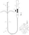
- FIG. 1 schematically depicts a steerable catheter system 10 having a reusable handle 12 and a disposable elongated body 14 that may be attached and detached from the handle.
- the catheter body 14 generally comprises an elongated tubular construction and may have an axial or central lumen.
- the catheter body 14 is flexible, i.e., bendable, but substantially non-compressible along its length.
- the catheter body 14 can be of any suitable construction and made of any suitable material.
- an outer wall may be made of polyurethane or PEBAX.
- the outer wall may also include an imbedded braided mesh of stainless steel or the like to increase torsional stiffness of the catheter body 14 so that when the handle 12 is rotated, a tip section 16 will rotate in a corresponding manner.
- the outer diameter of the catheter body 14 is not critical, and will vary depending on the intended application of the catheter. As a representative example, the diameter may be about 8 french or less.
- the thickness of the outer wall is not critical, but is thin enough so that the catheter body 14 can accommodate deflection members (e.g., puller wires), lead wires, and any other desired wires, cables or tubings while maintaining the desired outer diameter.
- the inner surface of the outer wall may be lined with a stiffening tube to provide improved torsional stability.
- the outer wall may have an outer diameter of from about 0.23 cm (0.090 inch) to about 2.4 cm (0.94 inch) and an inner diameter of from about 0.15 cm (0.061 inch) to about 0.17 cm (0.065 inch).
- the overall length of catheter system 10 may vary depending on the intended application, and may be about 1.2 m (48 inches) in some embodiments.
- Handle 12 and its components may be formed from suitable metals and/or polymeric materials and has an actuator 18 configured as a rotating member, taking the form of a thumb wheel in this embodiment, that actuates one or more deflection members, such as puller wires as described in further detail below.
- the control handle may also include a tension knob 20 that enables the user to adjust the ease by which the actuator 18 can be rotated, or may lock actuator 18 in a desired position.
- Manipulation of actuator 18 may impart a desired degree of deflection in tip section 16, which may be bi-directional as indicated in the figure. In other embodiments, uni-directional or other types of deflection may be employed.
- thumb wheel actuator is depicted in this embodiment, it will be appreciated that any suitable actuator design may be employed as desired, including sliders, pistons, rocker handles or the like. Exemplary details of deflection assemblies and control handles are described in co-pending U.S. application Ser. No. 12/346,834, filed Dec. 30, 2008 , entitled DEFLECTABLE SHEATH INTRODUCER, and commonly-owned U.S. Patent. Nos. 8,137,308, issued March 20, 2012 , entitled CATHETER WITH ADJUSTABLE DEFLECTION SENSITIVITY and 8,348,888, issued Jan. 8, 2013 , entitled STEERING MECHANISM FOR BI-DIRECTIONAL CATHETER, the entire disclosures of each are hereby incorporated by reference.
- catheter system 10 is configured for use in a electrophysiologic (EP) procedure, such as for mapping, pacing and/or ablation in the heart.
- distal tip section 16 may have multiple electrodes, including ring electrodes 22 and tip electrode 24, which may be irrigated if desired as depicted.
- Ring electrodes 22 may range in length from about 1 mm to about 3 mm, and may be spaced apart in any fashion as desired so long as their edges do not touch.
- the electrodes may be used for mapping, pacing, ablation or other operations and may be perforated to deliver irrigation fluid for controlling tissue temperature during the procedure.
- Handle 12 may incorporate a printed circuit board (PCB) 25 (shown in phantom in FIG.
- PCB printed circuit board
- PCB 25 may include a microprocessor for storing or preprocessing data measured by the electrodes to facilitate communication with a patient interface unit or other similar equipment.
- FIG. 2 A cross section of catheter body 14, taken at A-A, is shown in FIG. 2 .
- two off-axis lumens 26 and 28 accommodate puller wires 30, which are slidable within the lumens so that manipulation of actuator 18 may be used to deflect tip section 16.
- Catheter body 14 may have additional lumens as warranted by the intended application.
- lumen 32 may carry lead wires and thermocouple wires 34 for communicating electrical signals to and from ring electrodes 22 and tip electrode 24.
- lumen 36 may carry location sensor cables 38, used in conjunction with a positioning system, such as the CARTO ® 3 System embodying methods as disclosed in U.S. Pat. Nos.
- Each puller wire 30 is made of any suitable metal, such as stainless steel or Nitinol, or other appropriate material, and may have a coating or sleeve 44 of Teflon ® or the like. Each puller wire 30 may have a diameter ranging from about 0.15 mm (0.006 inch) to about 0.025 mm (0.0010 inch). The puller wires 30 may be secured at a desired location in tip section 16, such as by welding to tip electrode 24 or through an anchor embedded in the material of the catheter body.
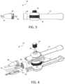
- disposable catheter body 14 may be attached to handle 12 as shown in FIG. 1 and may be detached as shown in FIG. 3 .
- the proximal end of catheter body 14 has a coupling in the form of fitting 46 with external threads that is configured to mate with threaded housing 48 that is rotatably mounted to handle 12 and features complementary internal threads.
- the tapered profile of fitting 46 also provides a strain relief function by creating a more gradual transition between the rigid handle 12 and the more flexible catheter body 14.
- any suitable connection mechanism may be employed, including snaps, latches, bayonet locks, Luer hubs or others.
- Each puller wire 30 is secured to interconnects 50 (only one visible in this view.)
- interconnects 50 For the sake of clarity, the couplings associated with lead and thermocouple wires 34, sensor cables 38 and irrigation tubing 42 are not shown, but any suitable fluidic or electrical connector system may be employed as desired.
- edge connectors provided in fitting 46 and threaded housing may be used to couple electrode lead and thermocouple wires 34 and/or sensor cables 38 with PCB 25,
- any suitable releasable attachment between handle 12 and catheter body 14 may be employed, such as a snap fit connection, a pneumatic push-in connection or the like.
- FIG. 4 Further details of the actuation mechanism of handle 12 are shown in the exploded view of FIG. 4 .
- the complementary halves of fitting 46 define internal supports 52 upon which interconnects 50 travel.
- Sliding member in the form of two racks 54 are deployed within handle 12, longitudinally moving within guides 56 formed by the complementary halves of handle 12 at a distal location and are configured to allow longitudinal movement and restrict off-axis motion of racks 54.
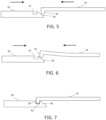
- Cooperating structures are positioned at the proximal ends of interconnects 50 and at the distal ends of racks to allow a releasable engagement. In this embodiment, the ends have a hook-shaped configuration. Interaction of these elements is schematically depicted in FIGs. 5-7 .
- each rack 54 contacts the proximal end of each interconnect as shown in FIG. 5 .
- projection 58 of rack 54 engages ramp 60 of interconnect 50.
- deflecting rack 54 which may be formed of any sufficiently resilient material.
- interconnects 50 are held in position by supports 52 as rack 54 deflects.
- a releasable engagement between rack 54 and interconnect 50 is formed when projection 58 is positioned coextensively over recess 62, allowing rack 54 to return to its nominal configuration, with projection 58 fitting within recess 62 as shown in FIG. 7 .
- a similar releaseable engagement between rack 54 and interconnect 50 may be achieved in other embodiments by reversing the configuration of the cooperating ends.
- Projection 58 and recess 62 may be suitably sized to minimize play between rack 54 and interconnect 50.
- longitudinal motion of rack 54 is transmitted and causes a corresponding longitudinal motion of interconnect 50.
- other means may be used to releasably attach proximal ends of the puller wires with structures driven by one or more actuators, including a hook and loop connection, a snap fit connection or a magnetic connection, so that interconnect 50 and the sliding member rack 54 engage when handle 12 is attached to catheter body 14.
- rack 54 may be transmitted to the deflection member, puller wire 30, in response to manipulation of actuator 18.
- Interconnect 50 and rack 54 disengage when handle 12 is released from catheter body 14.
- only a single puller wire 30, interconnect 50 and rack 54 may be required.
- Other embodiments may include additional components as warranted following these principles to achieve deflection in different directions and/or planes.
- each rack 54 is coupled to actuator 18 by a cylindrical pin 64 that rides within a camming slot 66 formed in actuator 18.
- the pins 64 travel within slots 66, and due to the constraint of guides 56, movement of racks 54 is generally longitudinal.
- racks 54 are attached to interconnects 50 as described above when handle 12 is mated to catheter body 14, the longitudinal movements of racks 54 are translated to longitudinal movement of puller wires 30, as they are secured to interconnects 50.
- Puller wires 30 may be directly attached to interconnects 50, or may be coupled by a transitional material, such as a flexible cord, to reduce kinking of puller wires 30 when being moved.
- slots 66 may be designed to produce motion of the racks 54 with desired characteristics.
- slots 66 may be curved about a radius that displaces racks 54 at the same ratio of rotation to movement no matter what degree actuator 18 has already been turned, such as by having the same ratio throughout the range of travel of actuator 18.
- slots 66 may be configured to cause different ratios of motion at different degrees of rotation.
- the diameter of actuator 18 and length of slots 66 may determine the total amount of movement. In this embodiment, manipulation of actuator 18 causes coordinated movement of the puller wires 30, with one being withdrawn and the other advanced.
- actuator 18 may be coupled to racks 54 by one or more gears.
- tactile feedback may be provided when actuator 18 is in a neutral position corresponding to no deflection of tip section 16, such as by providing a detent at the appropriate position in the range of travel of actuator 18.
- Visual or audible indicators may also be employed.
- racks 54 may be biased by springs or other mechanisms to return to the neutral position. As such, when tension knob 20 is released, tip section 16 may revert to its non-deflected configuration.
- Other embodiments may exploit other mechanisms, such as a push button to allow free movement of racks 54 or otherwise allow them to return to their neutral positions.
- catheter system 10 represents a cost reduction as compared to conventional disposable catheters, in which the handle is discarded along with the catheter body after use. Since handle 12 is removably attached to catheter body 14, it may be reused following appropriate sterilization and cleaning so that only catheter body 14 need be discarded.
- the coupling provided by housing 48 and fitting 46 allows for attachment and release of catheter body 14 from handle 12, while simultaneously aligning racks 54 and interconnects 50 to be releasably engaged to transmit forces from actuator 18 to the deflection mechanisms, such as puller wires 30. Further, this coupling may also be used to form connections between wires, leads, cables and/or tubing that may be carried by catheter body 14. As desired, any or all of these components may either pass through handle 12 or connect directly to fitting 46. Further, the modularity of catheter system 10 allows multiple catheter bodies to be used with the same handle, for example to provide different capabilities or functionalities.
- each tubular shaft may split from a single coupling with the handle.
- each tubular shaft may connect via separate couplings or backshell connections with the handle.
- yet another alternative may involve one or more of the additional catheter bodies connecting to apparatus other than the handle depending on the functionality desired.
- each of the multiple catheter bodies may be employed for different purposes, such as forming an electrical conduit, an independent irrigation lumen or any other suitable function.
- the handle may have interior or exterior channels as appropriate to route the catheter body's tubular shafts to the proximal end of the handle.
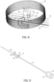
- FIG. 9 schematically depicts a disposable catheter body 14 having similar characteristics to those described above.
- Fitting 70 may have functionality generally equivalent to fitting 46 with regards to facilitating connection to a reusable handle (not shown in this view).
- Fitting 70 may be overmolded onto catheter body 14 or connected though any other suitable means.
- fitting 70 may include frangible support 72 that is configured to retain interconnects 74 in a defined orientation and position with respect to catheter body 14 during attachment of the handle.
- a backshell 76 may be secured to the catheter body 14 by overmolding or other suitable technique to connect with the handle as desired.
- support 72 may have sufficient strength to maintain interconnects 74 in a position to mate with structures equivalent to racks 54, or to be releasably attached through any other suitable interaction, including magnetic, hook and loop, or snap fit as described above, it also may be configured to break upon application of force through an actuator on the handle. As will be appreciated, tailoring the strength of support 72 may be achieved by selecting the appropriate material, such as a polymeric material, by adjusting its thickness or other structural dimension, or both. As desired, a PCB 78 having similar functionality to PCB 25 may be incorporated into the disposable catheter body rather than the handle, such as in backshell 76 as indicated or in any other suitable location. PCB may be used as an alternative to or in conjunction with PCB 25 depending on the embodiment.
Landscapes
- Health & Medical Sciences (AREA)
- Life Sciences & Earth Sciences (AREA)
- Engineering & Computer Science (AREA)
- Heart & Thoracic Surgery (AREA)
- Veterinary Medicine (AREA)
- Animal Behavior & Ethology (AREA)
- Public Health (AREA)
- Biomedical Technology (AREA)
- General Health & Medical Sciences (AREA)
- Surgery (AREA)
- Biophysics (AREA)
- Medical Informatics (AREA)
- Physics & Mathematics (AREA)
- Molecular Biology (AREA)
- Cardiology (AREA)
- Pathology (AREA)
- Nuclear Medicine, Radiotherapy & Molecular Imaging (AREA)
- Radiology & Medical Imaging (AREA)
- Pulmonology (AREA)
- Anesthesiology (AREA)
- Hematology (AREA)
- Vascular Medicine (AREA)
- Mechanical Engineering (AREA)
- Otolaryngology (AREA)
- Plasma & Fusion (AREA)
- Optics & Photonics (AREA)
- Physiology (AREA)
- Human Computer Interaction (AREA)
- Media Introduction/Drainage Providing Device (AREA)
- External Artificial Organs (AREA)
- Infusion, Injection, And Reservoir Apparatuses (AREA)
- Electrotherapy Devices (AREA)
Description
- This invention relates to a catheter having a reusable control handle and a steerable disposable catheter body.
- Medical catheterizations are routinely carried for many procedures. In one representative example, cardiac arrhythmias including atrial fibrillation may be diagnosed as well as treated by employing a variety of catheters to access the patient's heart in a minimally invasive manner. Diagnosing such conditions may involve mapping the cardiac tissue to locate aberrant electrical pathways and currents within the heart, as well as to determine mechanical and other aspects of cardiac activity. Various methods and devices have been described for mapping the heart. Such methods and devices are described, for example, in
U.S. Pat. Nos. 5,471,982 ,5,391,199 and5,718,241 and inPCT patent publications WO94/06349 WO96/05768 WO97/24981 - To that end, directional catheters have been designed to be deflectable, such as by manipulation of a puller wire or other deflection member disposed within an off-axis lumen and attached to a distal location of the catheter. Correspondingly, applying tension to the puller wire causes the tip of the catheter to deflect. Various designs exist, including uni-directional catheters that employ a single puller wire and bi-directional catheters that may have two puller wires extending within opposing off-axis lumens. More complex designs featuring a greater number of puller wires are also possible. Such catheters typically have a control handle at their distal end which have a thumb knob, a rotatable grip or other actuation mechanism that is manipulated by an electrophysiologist to position a distal end of the catheter at the desired location and/or operate electrode assemblies, such as contraction, expansion, deployment, retraction, etc.
- As with all medical equipment, prevention of iatrogenic conditions is of paramount concern. Ensuring sterility of the catheter may help minimize the risk of transmitting infectious agents. One strategy involves using new equipment with each procedure. With more complex equipment, such as the catheters of this disclosure, this may represent a significant cost. To address this concern, the equipment may be cleaned and sterilized before the next use. However, costs and delays are associated with this strategy as well, particularly due to the difficulties involved with cleaning the elongated catheter shaft which typically has multiple lumens. Accordingly, it would be desirable to provide a catheter system that reduces these drawbacks by employing a reusable handle mechanism that may be readily sterilized for use with a disposable catheter body, particularly in light of the observation that the handle represent a significant fraction of the overall cost. Similarly, it would be desirable to provide a catheter system having a detachable connection between the reusable handle and the disposable shaft that couples the actuation mechanisms of the handle with components of the catheter shaft, such as puller wires, that control deflection of the catheter tip. The techniques of this disclosure as described in the following materials satisfy these and other needs.
-
US2012/197190A1 describes a medical device with a handle and a catheter. The handle can include a body having a proximal end and a distal end, an actuator moveably coupled to the body, and a handle control member coupled to the actuator, wherein the actuator can be configured to move relative to the body to move the handle control member. The catheter can include a shaft having a proximal end and a distal end, wherein the proximal end of the shaft and the distal end of the body can be configured for releasable coupling. The catheter can also include a steering section located along the shaft and a catheter control member coupled to the steering section. A securing member may move relative to at least one of the handle and the catheter to releasably couple the handle control member to the catheter control member.US2003/028182A1 describes a cryoablation catheter handle. - The present disclosure is directed to a steerable catheter with an elongated, tubular catheter body having a proximal end and a tip section at a distal end, and at least one lumen extending therethrough. At least one deflection member may be slidably disposed within the lumen, secured at a distal end to the tip section and terminating in an interconnect at the proximal end. A handle is configured to be releasably attached to the proximal end of the catheter body, having at least one actuator and at least one sliding member associated with the handle and coupled to the actuator, such that manipulation of the actuator causes relative longitudinal movement with respect to the handle. The interconnect and the sliding member engage when the handle is attached to the catheter body so that the relative longitudinal movement of the sliding member is transmitted to the deflection member and wherein the interconnect and the sliding member disengage when the handle is released from the catheter body.
- In one aspect, the actuator comprises a rotating member coupled to the sliding member by a pin traveling within a camming slot of the rotating member.
- In one aspect, the catheter body may have at least two lumens extending therethrough, with two deflection members, each slidably disposed within respective lumens, both secured at a distal end to the tip section and terminating in interconnects at the proximal ends, and the actuator may be coupled to the two sliding members, wherein each interconnect and each sliding member engage when the handle is attached to the catheter body so that the relative longitudinal movement of each sliding member is transmitted to each engaged deflection member and wherein each interconnect and each sliding member disengage when the handle is released from the catheter body. Correspondingly, the actuator may be a rotating member coupled to each sliding member by pins traveling within respective camming slots of the rotating member so that rotation of the actuator in a first direction causes movement of one sliding member in a relatively distal direction and movement of the other sliding member in a relatively proximal direction, while rotation of the actuator in a second direction causes movement of the one sliding member in a relatively proximal direction and movement of the other sliding member in a relatively distal direction.
- In one aspect, the camming slot of the actuator may have a radius that displaces the sliding member at a same ratio of rotation to movement over a range of travel of the actuator.
- In one aspect, the engagement of the sliding member and the interconnect may involve a projection fitting within a recess. A ramp on one of the sliding member and the interconnect may deflect the projection until positioned coextensively with the recess.
- In one aspect, the sliding member may travel within a guide formed in a distal portion of the handle.
- In one aspect, the catheter body may be attached to the handle by a threaded housing.
- In one aspect, the interconnect may be stabilized with respect to the catheter body prior to attachment to the handle by a frangible support. The frangible support may be configured to break following manipulation of the actuator by a user.
- In one aspect, electronic circuitry may be integrated into at least one of the catheter body and the handle such that the electronic circuitry is in communication with components in the catheter body when the handle is attached to the catheter body.
- This disclosure also includes a handle for a steerable catheter having a coupling for attaching a proximal end of a catheter body, at least one actuator and at least one sliding member associated with the handle and coupled to the actuator, such that manipulation of the actuator causes relative longitudinal movement with respect to the handle. The catheter body to be releasably attached to the handle has at least one deflection member slidably disposed within a lumen, secured at a distal end to a tip section and terminating in an interconnect at the proximal end. The sliding member may be configured to engage with the interconnect when the handle is attached to the catheter body so that the relative longitudinal movement of the sliding member is transmitted to the deflection member and the sliding member may be configured to disengage from the interconnect when the handle is released from the catheter body.
- In one aspect, the actuator may have a rotating member coupled to the sliding member by a pin traveling within a camming slot of the rotating member.
- In one aspect, the catheter body may have at least two lumens extending therethrough, with two deflection members, each slidably disposed within respective lumens, both secured at a distal end to the tip section and terminating in interconnects at the proximal ends, and wherein the actuator is coupled to two sliding members, wherein each sliding member is configured to engage with each interconnect when the handle is attached to the catheter body so that the relative longitudinal movement of each sliding member is transmitted to each engaged deflection member and wherein each sliding member is configured to disengage from each interconnect when the handle is released from the catheter body. The actuator may have a rotating member coupled to each sliding member by pins traveling within respective camming slots of the rotating member so that rotation of the actuator in a first direction causes movement of one sliding member in a relatively distal direction and movement of the other sliding member in a relatively proximal direction, while rotation of the actuator in a second direction causes movement of the one sliding member in a relatively proximal direction and movement of the other sliding member in a relatively distal direction.
- In one aspect, the camming slot of the actuator may have a radius that displaces the sliding member at a same ratio of rotation to movement over a range of travel of the actuator.
- In one aspect, the sliding member may be configured to engage the interconnect by a projection fitting within a recess.
- In one aspect, the sliding member may travel within a guide formed in a distal portion of the handle.
- In one aspect, electronic circuitry may be integrated into the catheter body such that the electronic circuitry is in communication with components in the catheter body when the handle is attached to the catheter body.
- This disclosure also includes an elongated, tubular catheter body having a proximal end and a tip section at a distal end, at least one lumen extending therethrough and at least one deflection member slidably disposed within the lumen, secured at a distal end to the tip section and terminating in an interconnect at the proximal end. The proximal end of the catheter body may be configured to be releasably attached to a handle having at least one sliding member, wherein the interconnect and the sliding member engage when the handle is attached to the catheter body so that the relative longitudinal movement of the sliding member is transmitted to the deflection member and wherein the interconnect and the sliding member disengage when the handle is released from the catheter body.
- In one aspect, the interconnect may be stabilized with respect to the catheter body prior to attachment to the handle by a frangible support.
- In one aspect, electronic circuitry may be integrated into the catheter body such that the electronic circuitry is in communication with the handle when the handle is attached to the catheter body.
- Further features and advantages will become apparent from the following and more particular description of the preferred embodiments of the disclosure, as illustrated in the accompanying drawings, and in which like referenced characters generally refer to the same parts or elements throughout the views, and in which:
-
FIG. 1 is a schematic elevational view of a catheter system having a reusable handle and a disposable catheter body, according to one embodiment. -
FIG. 2 is a cross section view of the catheter body ofFIG. 1 , according to one embodiment. -
FIG. 3 is a partial schematic view of the reusable handle and the disposable catheter body in a detached configuration, according to one embodiment. -
FIG. 4 is an exploded view of the reusable handle and the disposable catheter body in the detached configuration ofFIG. 2 , according to one embodiment. -
FIGs. 5-7 schematically depict the releasable engagement of a sliding member of the reusable handle with an interconnect of the disposable catheter body, according to one embodiment. -
FIG. 8 is a transparent view of the actuator, showing the coupling of sliding members, according to one embodiment. -
FIG. 9 is a schematic, elevational view of an embodiment of a catheter body having deflection member interconnects stabilized by a frangible support, according to one embodiment. - At the outset, it is to be understood that this disclosure is not limited to particularly exemplified materials, architectures, routines, methods or structures as such may vary. Thus, although a number of such options, similar or equivalent to those described herein, can be used in the practice or embodiments of this disclosure, the preferred materials and methods are described herein.
- It is also to be understood that the terminology used herein is for the purpose of describing particular embodiments of this disclosure only and is not intended to be limiting.
- The detailed description set forth below in connection with the appended drawings is intended as a description of exemplary embodiments of the present disclosure and is not intended to represent the only exemplary embodiments in which the present disclosure can be practiced. The term "exemplary" used throughout this description means "serving as an example, instance, or illustration," and should not necessarily be construed as preferred or advantageous over other exemplary embodiments. The detailed description includes specific details for the purpose of providing a thorough understanding of the exemplary embodiments of the specification. It will be apparent to those skilled in the art that the exemplary embodiments of the specification may be practiced without these specific details. In some instances, well known structures and devices are shown in block diagram form in order to avoid obscuring the novelty of the exemplary embodiments presented herein.
- For purposes of convenience and clarity only, directional terms, such as top, bottom, left, right, up, down, over, above, below, beneath, rear, back, and front, may be used with respect to the accompanying drawings. These and similar directional terms should not be construed to limit the scope of the disclosure in any manner.
- Unless defined otherwise, all technical and scientific terms used herein have the same meaning as commonly understood by one having ordinary skill in the art to which the disclosure pertains.
- Finally, as used in this specification and the appended claims, the singular forms "a, "an" and "the" include plural referents unless the content clearly dictates otherwise.
- To help illustrate aspects of this disclosure,
FIG. 1 schematically depicts asteerable catheter system 10 having areusable handle 12 and a disposableelongated body 14 that may be attached and detached from the handle. Thecatheter body 14 generally comprises an elongated tubular construction and may have an axial or central lumen. Thecatheter body 14 is flexible, i.e., bendable, but substantially non-compressible along its length. Thecatheter body 14 can be of any suitable construction and made of any suitable material. In one embodiment, an outer wall may be made of polyurethane or PEBAX. The outer wall may also include an imbedded braided mesh of stainless steel or the like to increase torsional stiffness of thecatheter body 14 so that when thehandle 12 is rotated, atip section 16 will rotate in a corresponding manner. The outer diameter of thecatheter body 14 is not critical, and will vary depending on the intended application of the catheter. As a representative example, the diameter may be about 8 french or less. Likewise, the thickness of the outer wall is not critical, but is thin enough so that thecatheter body 14 can accommodate deflection members (e.g., puller wires), lead wires, and any other desired wires, cables or tubings while maintaining the desired outer diameter. As warranted, the inner surface of the outer wall may be lined with a stiffening tube to provide improved torsional stability. For purposes of illustration only, the outer wall may have an outer diameter of from about 0.23 cm (0.090 inch) to about 2.4 cm (0.94 inch) and an inner diameter of from about 0.15 cm (0.061 inch) to about 0.17 cm (0.065 inch). Likewise, the overall length ofcatheter system 10 may vary depending on the intended application, and may be about 1.2 m (48 inches) in some embodiments. -
Handle 12 and its components may be formed from suitable metals and/or polymeric materials and has anactuator 18 configured as a rotating member, taking the form of a thumb wheel in this embodiment, that actuates one or more deflection members, such as puller wires as described in further detail below. The control handle may also include atension knob 20 that enables the user to adjust the ease by which theactuator 18 can be rotated, or may lockactuator 18 in a desired position. Manipulation ofactuator 18 may impart a desired degree of deflection intip section 16, which may be bi-directional as indicated in the figure. In other embodiments, uni-directional or other types of deflection may be employed. Although a thumb wheel actuator is depicted in this embodiment, it will be appreciated that any suitable actuator design may be employed as desired, including sliders, pistons, rocker handles or the like. Exemplary details of deflection assemblies and control handles are described in co-pendingU.S. application Ser. No. 12/346,834, filed Dec. 30, 2008 U.S. Patent. Nos. 8,137,308, issued March 20, 2012 , entitled CATHETER WITH ADJUSTABLE DEFLECTION SENSITIVITY and8,348,888, issued Jan. 8, 2013 , entitled STEERING MECHANISM FOR BI-DIRECTIONAL CATHETER, the entire disclosures of each are hereby incorporated by reference. - In the depicted embodiment,
catheter system 10 is configured for use in a electrophysiologic (EP) procedure, such as for mapping, pacing and/or ablation in the heart. As such,distal tip section 16 may have multiple electrodes, includingring electrodes 22 andtip electrode 24, which may be irrigated if desired as depicted.Ring electrodes 22 may range in length from about 1 mm to about 3 mm, and may be spaced apart in any fashion as desired so long as their edges do not touch. As will be appreciated, the electrodes may be used for mapping, pacing, ablation or other operations and may be perforated to deliver irrigation fluid for controlling tissue temperature during the procedure.Handle 12 may incorporate a printed circuit board (PCB) 25 (shown in phantom inFIG. 1 ) or equivalent circuitry to be used in conjunction with controlling, receiving and/or delivering signals to the electrodes in thedistal tip section 16 or any other components, such as location sensors, thermocouples or the like. For example,PCB 25 may include a microprocessor for storing or preprocessing data measured by the electrodes to facilitate communication with a patient interface unit or other similar equipment. However, these and other aspects associated with EP catheters are intended as illustrations only and the techniques of this disclosure for providing a reusable handle with a steerable, disposable catheter body are relevant for any catheter that may be used in any procedure for which steerability is desirable. - A cross section of
catheter body 14, taken at A-A, is shown inFIG. 2 . In this embodiment, two off-axis lumens puller wires 30, which are slidable within the lumens so that manipulation ofactuator 18 may be used to deflecttip section 16.Catheter body 14 may have additional lumens as warranted by the intended application. For example,lumen 32 may carry lead wires andthermocouple wires 34 for communicating electrical signals to and fromring electrodes 22 andtip electrode 24. Further,lumen 36 may carrylocation sensor cables 38, used in conjunction with a positioning system, such as the CARTO® 3 System embodying methods as disclosed inU.S. Pat. Nos. 6,226,542 , and6,301,496 , and6,892,091 , available from Biosense Webster, Inc. (Diamond Bar, CA), while lumen 40 may carryirrigation tubing 42. Eachpuller wire 30 is made of any suitable metal, such as stainless steel or Nitinol, or other appropriate material, and may have a coating orsleeve 44 of Teflon® or the like. Eachpuller wire 30 may have a diameter ranging from about 0.15 mm (0.006 inch) to about 0.025 mm (0.0010 inch). Thepuller wires 30 may be secured at a desired location intip section 16, such as by welding to tipelectrode 24 or through an anchor embedded in the material of the catheter body. - As discussed above,
disposable catheter body 14 may be attached to handle 12 as shown inFIG. 1 and may be detached as shown inFIG. 3 . In this embodiment, the proximal end ofcatheter body 14 has a coupling in the form of fitting 46 with external threads that is configured to mate with threadedhousing 48 that is rotatably mounted to handle 12 and features complementary internal threads. The tapered profile of fitting 46 also provides a strain relief function by creating a more gradual transition between therigid handle 12 and the moreflexible catheter body 14. In other embodiments, any suitable connection mechanism may be employed, including snaps, latches, bayonet locks, Luer hubs or others. Eachpuller wire 30 is secured to interconnects 50 (only one visible in this view.) For the sake of clarity, the couplings associated with lead andthermocouple wires 34,sensor cables 38 andirrigation tubing 42 are not shown, but any suitable fluidic or electrical connector system may be employed as desired. For example, edge connectors provided in fitting 46 and threaded housing may be used to couple electrode lead andthermocouple wires 34 and/orsensor cables 38 withPCB 25, In other embodiments, any suitable releasable attachment betweenhandle 12 andcatheter body 14 may be employed, such as a snap fit connection, a pneumatic push-in connection or the like. - Further details of the actuation mechanism of
handle 12 are shown in the exploded view ofFIG. 4 . As depicted, the complementary halves of fitting 46 defineinternal supports 52 upon which interconnects 50 travel. Sliding member in the form of tworacks 54 are deployed withinhandle 12, longitudinally moving withinguides 56 formed by the complementary halves ofhandle 12 at a distal location and are configured to allow longitudinal movement and restrict off-axis motion ofracks 54. Cooperating structures are positioned at the proximal ends ofinterconnects 50 and at the distal ends of racks to allow a releasable engagement. In this embodiment, the ends have a hook-shaped configuration. Interaction of these elements is schematically depicted inFIGs. 5-7 . Ashandle 12 andcatheter body 14 are brought together, the distal end of eachrack 54 contacts the proximal end of each interconnect as shown inFIG. 5 . In particular,projection 58 ofrack 54 engagesramp 60 ofinterconnect 50. Further relative movement betweenrack 54 andinterconnect 50 causesprojection 58 to ride along the surface oframp 60 as shown inFIG. 6 , deflectingrack 54, which may be formed of any sufficiently resilient material. Notably, interconnects 50 are held in position by supports 52 asrack 54 deflects. Finally, a releasable engagement betweenrack 54 andinterconnect 50 is formed whenprojection 58 is positioned coextensively overrecess 62, allowingrack 54 to return to its nominal configuration, withprojection 58 fitting withinrecess 62 as shown inFIG. 7 . As will be appreciated, a similar releaseable engagement betweenrack 54 andinterconnect 50 may be achieved in other embodiments by reversing the configuration of the cooperating ends.Projection 58 andrecess 62 may be suitably sized to minimize play betweenrack 54 andinterconnect 50. In this engaged configuration, longitudinal motion ofrack 54 is transmitted and causes a corresponding longitudinal motion ofinterconnect 50. Alternatively, other means may be used to releasably attach proximal ends of the puller wires with structures driven by one or more actuators, including a hook and loop connection, a snap fit connection or a magnetic connection, so thatinterconnect 50 and the slidingmember rack 54 engage when handle 12 is attached tocatheter body 14. Accordingly, relative longitudinal movement ofrack 54 may be transmitted to the deflection member,puller wire 30, in response to manipulation ofactuator 18.Interconnect 50 andrack 54 disengage when handle 12 is released fromcatheter body 14. In embodiments featuring uni-directional deflection, only asingle puller wire 30,interconnect 50 andrack 54 may be required. Other embodiments may include additional components as warranted following these principles to achieve deflection in different directions and/or planes. - Returning to
FIG. 4 , it may be seen that eachrack 54 is coupled toactuator 18 by acylindrical pin 64 that rides within acamming slot 66 formed inactuator 18. Correspondingly, whenactuator 18 is turned, thepins 64 travel withinslots 66, and due to the constraint ofguides 56, movement ofracks 54 is generally longitudinal. Further, sinceracks 54 are attached to interconnects 50 as described above whenhandle 12 is mated tocatheter body 14, the longitudinal movements ofracks 54 are translated to longitudinal movement ofpuller wires 30, as they are secured to interconnects 50.Puller wires 30 may be directly attached to interconnects 50, or may be coupled by a transitional material, such as a flexible cord, to reduce kinking ofpuller wires 30 when being moved. As will be appreciated,slots 66 may be designed to produce motion of theracks 54 with desired characteristics. For example,slots 66 may be curved about a radius that displacesracks 54 at the same ratio of rotation to movement no matter whatdegree actuator 18 has already been turned, such as by having the same ratio throughout the range of travel ofactuator 18. In other embodiments,slots 66 may be configured to cause different ratios of motion at different degrees of rotation. Further, the diameter ofactuator 18 and length ofslots 66 may determine the total amount of movement. In this embodiment, manipulation ofactuator 18 causes coordinated movement of thepuller wires 30, with one being withdrawn and the other advanced. - Additional details regarding the interaction between
actuator 18 andracks 54 may be seen in the partially transparent view shown inFIG. 8 . This figure depictsactuator 18 at one end of its range of rotational motion, such that clockwise rotation from this position causes pins 64 to travel withinslots 66. Sincepins 64 project fromracks 54, the racks slide longitudinally in response to rotation ofactuator 18.Actuator 18 pivots aroundaxle 68, which may be shared with tension knob 20 (not shown in this view.) Although this embodiment relates to a configuration in which actuator 18 is a thumb wheel that is directly manipulated by the user, similar functionality may be achieved by using a rotating member having camming slots that is driven by a separate actuator. Alternatively,actuator 18 may be coupled toracks 54 by one or more gears. As desired, tactile feedback may be provided whenactuator 18 is in a neutral position corresponding to no deflection oftip section 16, such as by providing a detent at the appropriate position in the range of travel ofactuator 18. Visual or audible indicators may also be employed. In a further aspect, racks 54 may be biased by springs or other mechanisms to return to the neutral position. As such, whentension knob 20 is released,tip section 16 may revert to its non-deflected configuration. Other embodiments may exploit other mechanisms, such as a push button to allow free movement ofracks 54 or otherwise allow them to return to their neutral positions. - From the above, it will be appreciated that
catheter system 10 represents a cost reduction as compared to conventional disposable catheters, in which the handle is discarded along with the catheter body after use. Sincehandle 12 is removably attached tocatheter body 14, it may be reused following appropriate sterilization and cleaning so thatonly catheter body 14 need be discarded. The coupling provided byhousing 48 and fitting 46 allows for attachment and release ofcatheter body 14 fromhandle 12, while simultaneously aligningracks 54 and interconnects 50 to be releasably engaged to transmit forces fromactuator 18 to the deflection mechanisms, such aspuller wires 30. Further, this coupling may also be used to form connections between wires, leads, cables and/or tubing that may be carried bycatheter body 14. As desired, any or all of these components may either pass throughhandle 12 or connect directly to fitting 46. Further, the modularity ofcatheter system 10 allows multiple catheter bodies to be used with the same handle, for example to provide different capabilities or functionalities. - Further, although the embodiments discussed above have been in the context of a single disposable catheter body that is releasably attached to a reusable handle, multiple catheter bodies may be employed as desired. For example, two or more tubular shafts may split from a single coupling with the handle. Alternatively, each tubular shaft may connect via separate couplings or backshell connections with the handle. Yet another alternative may involve one or more of the additional catheter bodies connecting to apparatus other than the handle depending on the functionality desired. As will be appreciated, each of the multiple catheter bodies may be employed for different purposes, such as forming an electrical conduit, an independent irrigation lumen or any other suitable function. Depending on the embodiment, such as those incorporating a backhsell connection, the handle may have interior or exterior channels as appropriate to route the catheter body's tubular shafts to the proximal end of the handle.
- In another aspect, the puller wires and associated interconnects may be temporarily held in a defined relationship, stabilizing the interconnect(s) to facilitate engagement of the actuator mechanism during connection of the reusable handle. For example,
FIG. 9 schematically depicts adisposable catheter body 14 having similar characteristics to those described above. Fitting 70 may have functionality generally equivalent to fitting 46 with regards to facilitating connection to a reusable handle (not shown in this view). Fitting 70 may be overmolded ontocatheter body 14 or connected though any other suitable means. In particular, fitting 70 may includefrangible support 72 that is configured to retaininterconnects 74 in a defined orientation and position with respect tocatheter body 14 during attachment of the handle. Abackshell 76 may be secured to thecatheter body 14 by overmolding or other suitable technique to connect with the handle as desired. Whilesupport 72 may have sufficient strength to maintaininterconnects 74 in a position to mate with structures equivalent toracks 54, or to be releasably attached through any other suitable interaction, including magnetic, hook and loop, or snap fit as described above, it also may be configured to break upon application of force through an actuator on the handle. As will be appreciated, tailoring the strength ofsupport 72 may be achieved by selecting the appropriate material, such as a polymeric material, by adjusting its thickness or other structural dimension, or both. As desired, aPCB 78 having similar functionality toPCB 25 may be incorporated into the disposable catheter body rather than the handle, such as inbackshell 76 as indicated or in any other suitable location. PCB may be used as an alternative to or in conjunction withPCB 25 depending on the embodiment. - The preceding description has been presented with reference to presently disclosed embodiments of the invention. Workers skilled in the art and technology to which this invention pertains will appreciate that alterations and changes in the described structure may be practiced without meaningfully departing from the principal, scope of this invention. As understood by one of ordinary skill in the art, the drawings are not necessarily to scale. Accordingly, the foregoing description should not be read as pertaining only to the precise structures described and illustrated in the accompanying drawings, but rather should be read consistent with and as support to the following claims which are to have their fullest and fair scope.
Claims (13)
- An elongated, tubular catheter body (14) comprising a proximal end and a tip section (16) at a distal end, at least one lumen (26, 28) extending therethrough and at least one deflection member (30) slidably disposed within the lumen, secured at a distal end to the tip section and terminating in an interconnect (50) at the proximal end; wherein the proximal end of the catheter body is configured to be releasably attached to a handle (12) having at least one sliding member (54), wherein the interconnect and the sliding member engage when the handle is attached to the catheter body so that the relative longitudinal movement of the sliding member is transmitted to the deflection member and wherein the interconnect and the sliding member disengage when the handle is released from the catheter body, wherein the interconnect is stabilized with respect to the catheter body prior to attachment to the handle by a frangible support (72).
- The catheter body of claim 1, further comprising electronic circuitry integrated into the catheter body such that the electronic circuitry is in communication with the handle when the handle is attached to the catheter body.
- A steerable catheter comprising:the elongated, tubular catheter body of claim 1; andthe handle, wherein the handle is configured to releasably attach to the proximal end of the catheter body, the handle comprising at least one actuator (18), wherein the at least one sliding member is coupled to the actuator, such that manipulation of the actuator causes relative longitudinal movement with respect to the handle.
- The steerable catheter of claim 3, wherein the actuator comprises a rotating member coupled to the sliding member by a pin (64) traveling within a camming slot (66) of the rotating member.
- The steerable catheter of claim 3, wherein the catheter body has at least two lumens extending therethrough, with two deflection members, each slidably disposed within respective lumens, both secured at a distal end to the tip section and terminating in interconnects at the proximal ends, and wherein the actuator is coupled to two sliding members,
wherein each interconnect and each sliding member engage when the handle is attached to the catheter body so that the relative longitudinal movement of each sliding member is transmitted to each engaged deflection member and wherein each interconnect and each sliding member disengage when the handle is released from the catheter body. - The steerable catheter of claim 5, wherein the actuator comprises a rotating member coupled to each sliding member by pins (64) traveling within respective camming slots (66) of the rotating member so that rotation of the actuator in a first direction causes movement of one sliding member in a relatively distal direction and movement of the other sliding member in a relatively proximal direction, while rotation of the actuator in a second direction causes movement of the one sliding member in a relatively proximal direction and movement of the other sliding member in a relatively distal direction.
- The steerable catheter of claim 4, wherein the camming slot of the actuator is configured to have a radius that displaces the sliding member at a same ratio of rotation to movement over a range of travel of the actuator.
- The steerable catheter of claim 3, wherein the engagement of the sliding member and the interconnect comprises a projection (58) fitting within a recess (62).
- The steerable catheter of claim 8, further comprising a ramp (60) on one of the sliding member and the interconnect to deflect the projection until positioned coextensively with the recess.
- The steerable catheter of claim 3, wherein the sliding member travels within a guide (56) formed in a distal portion of the handle.
- The steerable catheter of claim 3, wherein the catheter body is attached to the handle by a threaded housing (48).
- The steerable catheter of claim 3, wherein the frangible support is configured to break following manipulation of the actuator by a user.
- The steerable catheter of claim 3, further comprising electronic circuitry integrated into at least one of the catheter body and the handle such that the electronic circuitry is in communication with components in the catheter body when the handle is attached to the catheter body.
Applications Claiming Priority (2)
| Application Number | Priority Date | Filing Date | Title |
|---|---|---|---|
| US15/786,414 US10532187B2 (en) | 2017-10-17 | 2017-10-17 | Reusable catheter handle system |
| PCT/US2018/055128 WO2019079082A1 (en) | 2017-10-17 | 2018-10-10 | Reusable catheter handle system |
Publications (3)
| Publication Number | Publication Date |
|---|---|
| EP3697486A1 EP3697486A1 (en) | 2020-08-26 |
| EP3697486C0 EP3697486C0 (en) | 2024-07-17 |
| EP3697486B1 true EP3697486B1 (en) | 2024-07-17 |
Family
ID=64184182
Family Applications (1)
| Application Number | Title | Priority Date | Filing Date |
|---|---|---|---|
| EP18799909.9A Active EP3697486B1 (en) | 2017-10-17 | 2018-10-10 | Reusable catheter handle system |
Country Status (6)
| Country | Link |
|---|---|
| US (1) | US10532187B2 (en) |
| EP (1) | EP3697486B1 (en) |
| JP (1) | JP7282759B2 (en) |
| CN (1) | CN111246907B (en) |
| IL (1) | IL273506B2 (en) |
| WO (1) | WO2019079082A1 (en) |
Families Citing this family (25)
| Publication number | Priority date | Publication date | Assignee | Title |
|---|---|---|---|---|
| ES2751493T3 (en) | 2014-12-05 | 2020-03-31 | Fortimedix Surgical B V | Method for making a steerable instrument and said steerable instrument |
| CN111278497B (en) | 2017-11-28 | 2024-01-12 | 圣犹达医疗用品心脏病学部门有限公司 | lumen control catheter |
| EP3731747B1 (en) | 2018-03-13 | 2023-11-01 | St. Jude Medical, Cardiology Division, Inc. | Variable density mapping catheter |
| EP3749195B1 (en) | 2018-04-05 | 2023-10-18 | St. Jude Medical, Cardiology Division, Inc. | High density electrode mapping catheter |
| US20190350649A1 (en) | 2018-05-21 | 2019-11-21 | St. Jude Medical, Cardiology Division, Inc. | Radio-frequency ablation and direct current electroporation catheters |
| CN113873955B (en) | 2019-04-01 | 2024-10-25 | 富通麦迪资产二有限公司 | Steerable device including a hinge with a slotted structure |
| KR20210149102A (en) | 2019-04-08 | 2021-12-08 | 포티메딕스 에셋츠 Ii 비.브이. | A steerable mechanism comprising a removable portion |
| US12582300B2 (en) | 2019-04-08 | 2026-03-24 | Fortimedix Assets Ii B.V. | Steerable instrument comprising a detachable part |
| US12611522B2 (en) * | 2019-06-24 | 2026-04-28 | Medtronic, Inc. | Catheter handle with torque mechanism and valve relief component |
| EP3777946B1 (en) * | 2019-08-15 | 2023-01-18 | Biotronik Ag | Luer lock system for digital balloon catheter |
| US12544089B1 (en) | 2019-12-24 | 2026-02-10 | Farrow Medtech Llc | Wound-care apparatus and method for cleansing, desloughing, and debriding wounds |
| US11980383B2 (en) * | 2019-12-24 | 2024-05-14 | Farrow Medtech Llc | Wound-care apparatus and method for cleansing, desloughing, and debriding wounds |
| JP7119251B2 (en) * | 2020-03-17 | 2022-08-16 | 日本ライフライン株式会社 | Catheter Instruments, Catheter Bodies and Catheters |
| US12471754B2 (en) | 2020-04-24 | 2025-11-18 | Ambu A/S | Endoscope and a method for assembling an endoscope |
| CN115460963A (en) * | 2020-04-24 | 2022-12-09 | 安布股份有限公司 | Handle for endoscope |
| EP4167886B1 (en) | 2020-08-18 | 2024-05-01 | St. Jude Medical, Cardiology Division, Inc. | High-density electrode catheters with magnetic position tracking |
| EP4210553A4 (en) * | 2020-09-10 | 2024-11-20 | The Board of Trustees of the Leland Stanford Junior University | METHODS OF TREATMENT AND DEVICES FOR CURING INFLAMMATORY, ENDOCRINE, METABOLIC OR NEUROTRANSMITTER-RELATED DISORDERS |
| WO2022069960A1 (en) * | 2020-09-29 | 2022-04-07 | Baylis Medical Company Inc. | Steerable medical device, handle for a medical device, and method for operating a medical device |
| CN112932654B (en) * | 2021-01-26 | 2023-06-06 | 四川省人民医院 | An ablation electrode device |
| WO2022251426A1 (en) * | 2021-05-27 | 2022-12-01 | Becton, Dickinson And Company | Intravenous catheter device having a guidewire for actively repositioning a catheter tip |
| US20230181881A1 (en) * | 2021-12-14 | 2023-06-15 | Boston Scientific Scimed, Inc. | Steerable medical devices |
| NL2030160B1 (en) * | 2021-12-16 | 2023-06-28 | Fortimedix Assets Ii B V | Coupling controller for steerable instrument |
| US20230225595A1 (en) * | 2022-01-18 | 2023-07-20 | Neuwave Medical, Inc. | Steerable sheath and adjustable scope attachment |
| US12551658B2 (en) * | 2022-03-25 | 2026-02-17 | St. Jude Medical, Cardiology Division, Inc. | Steerable introducer with slide block divider |
| US20250032752A1 (en) * | 2023-07-28 | 2025-01-30 | Biosense Webster (Israel) Ltd. | Catheter with tactile indication of deflection |
Family Cites Families (46)
| Publication number | Priority date | Publication date | Assignee | Title |
|---|---|---|---|---|
| US5254088A (en) * | 1990-02-02 | 1993-10-19 | Ep Technologies, Inc. | Catheter steering mechanism |
| DE69315354T2 (en) | 1992-09-23 | 1998-03-19 | Endocardial Solutions Inc | ENDOCARD-MAPPING SYSTEM |
| US5471982A (en) | 1992-09-29 | 1995-12-05 | Ep Technologies, Inc. | Cardiac mapping and ablation systems |
| US5364351A (en) | 1992-11-13 | 1994-11-15 | Ep Technologies, Inc. | Catheter steering mechanism |
| US5441483A (en) * | 1992-11-16 | 1995-08-15 | Avitall; Boaz | Catheter deflection control |
| US5391199A (en) | 1993-07-20 | 1995-02-21 | Biosense, Inc. | Apparatus and method for treating cardiac arrhythmias |
| JP3708121B2 (en) | 1994-08-19 | 2005-10-19 | バイオセンス・インコーポレイテッド | Diagnosis and handling of medical equipment and video system |
| US5718241A (en) | 1995-06-07 | 1998-02-17 | Biosense, Inc. | Apparatus and method for treating cardiac arrhythmias with no discrete target |
| US5769858A (en) | 1995-10-20 | 1998-06-23 | Medtronic, Inc. | Locking stylet for extracting implantable lead or catheter |
| US5860953A (en) * | 1995-11-21 | 1999-01-19 | Catheter Imaging Systems, Inc. | Steerable catheter having disposable module and sterilizable handle and method of connecting same |
| US6007531A (en) | 1995-11-21 | 1999-12-28 | Catheter Imaging Systems, Inc. | Steerable catheter having disposable module and sterilizable handle and method of connecting same |
| AU710236B2 (en) | 1996-01-08 | 1999-09-16 | Biosense, Inc. | Cardiac electro-mechanics |
| US5826576A (en) * | 1996-08-08 | 1998-10-27 | Medtronic, Inc. | Electrophysiology catheter with multifunction wire and method for making |
| US6221070B1 (en) | 1996-10-18 | 2001-04-24 | Irvine Biomedical, Inc. | Steerable ablation catheter system having disposable shaft |
| US6013052A (en) * | 1997-09-04 | 2000-01-11 | Ep Technologies, Inc. | Catheter and piston-type actuation device for use with same |
| US6123699A (en) * | 1997-09-05 | 2000-09-26 | Cordis Webster, Inc. | Omni-directional steerable catheter |
| US6171277B1 (en) | 1997-12-01 | 2001-01-09 | Cordis Webster, Inc. | Bi-directional control handle for steerable catheter |
| US6200315B1 (en) * | 1997-12-18 | 2001-03-13 | Medtronic, Inc. | Left atrium ablation catheter |
| US6301496B1 (en) | 1998-07-24 | 2001-10-09 | Biosense, Inc. | Vector mapping of three-dimensionally reconstructed intrabody organs and method of display |
| US6226542B1 (en) | 1998-07-24 | 2001-05-01 | Biosense, Inc. | Three-dimensional reconstruction of intrabody organs |
| US20030028182A1 (en) | 1999-04-21 | 2003-02-06 | Cryocath Technologies Inc. | Cryoablation catheter handle |
| US6892091B1 (en) | 2000-02-18 | 2005-05-10 | Biosense, Inc. | Catheter, method and apparatus for generating an electrical map of a chamber of the heart |
| US7027851B2 (en) * | 2002-10-30 | 2006-04-11 | Biosense Webster, Inc. | Multi-tip steerable catheter |
| US7039450B2 (en) * | 2002-11-15 | 2006-05-02 | Biosense Webster, Inc. | Telescoping catheter |
| US8777889B2 (en) * | 2004-06-15 | 2014-07-15 | Ceramatec, Inc. | Apparatus and method for administering a therapeutic agent into tissue |
| AU2005228956B2 (en) | 2004-03-23 | 2011-08-18 | Boston Scientific Limited | In-vivo visualization system |
| US7377906B2 (en) | 2004-06-15 | 2008-05-27 | Biosense Webster, Inc. | Steering mechanism for bi-directional catheter |
| US7497853B2 (en) * | 2005-05-05 | 2009-03-03 | Enpath Medical Inc. | Deflectable catheter steering and locking system |
| US20070156114A1 (en) * | 2005-12-29 | 2007-07-05 | Worley Seth J | Deflectable catheter with a flexibly attached tip section |
| PL2077774T3 (en) | 2006-10-05 | 2015-02-27 | Erbe Elektromedizin | Tubular shaft instrument |
| WO2008045394A2 (en) | 2006-10-05 | 2008-04-17 | Tyco Healthcare Group Lp | Flexible endoscopic stitching devices |
| US7931616B2 (en) * | 2006-10-31 | 2011-04-26 | Biosense Webster, Inc. | Insert molded catheter puller member connectors and method of making |
| CN201098109Y (en) * | 2007-08-21 | 2008-08-13 | 复旦大学 | Disposable medical endoscope |
| US8257386B2 (en) | 2007-09-11 | 2012-09-04 | Cambridge Endoscopic Devices, Inc. | Surgical instrument |
| US8628545B2 (en) | 2008-06-13 | 2014-01-14 | Covidien Lp | Endoscopic stitching devices |
| US8137308B2 (en) | 2008-09-16 | 2012-03-20 | Biosense Webster, Inc. | Catheter with adjustable deflection sensitivity |
| US8808345B2 (en) | 2008-12-31 | 2014-08-19 | Medtronic Ardian Luxembourg S.A.R.L. | Handle assemblies for intravascular treatment devices and associated systems and methods |
| CN102883770B (en) * | 2010-05-11 | 2015-06-10 | 导管治疗有限公司 | catheter handle |
| CN103282076B (en) * | 2010-12-27 | 2016-05-11 | 导管治疗有限公司 | Modular Conduit |
| EP2670317B1 (en) | 2011-01-31 | 2021-09-15 | Boston Scientific Scimed, Inc. | Medical devices having releasable coupling |
| US9566048B1 (en) | 2011-04-26 | 2017-02-14 | Cardica, Inc. | Surgical instrument with discrete cammed articulation |
| US9162036B2 (en) * | 2011-12-30 | 2015-10-20 | Biosense Webster (Israel), Ltd. | Medical device control handle with multiple puller wires |
| JP6192951B2 (en) | 2013-03-01 | 2017-09-06 | テルモ株式会社 | Actuating member and medical device |
| US9174024B1 (en) * | 2013-03-15 | 2015-11-03 | St. Jude Medical Luxembourg Holdings S.À.R.L. | Steering control mechanisms for catheters |
| AU2014256841B2 (en) | 2013-04-22 | 2018-06-21 | Cathrx Ltd | An ablation catheter |
| DE102013208728A1 (en) | 2013-05-13 | 2014-11-13 | Aesculap Ag | Bendable tubular shaft |
-
2017
- 2017-10-17 US US15/786,414 patent/US10532187B2/en active Active
-
2018
- 2018-10-10 EP EP18799909.9A patent/EP3697486B1/en active Active
- 2018-10-10 CN CN201880067948.5A patent/CN111246907B/en active Active
- 2018-10-10 WO PCT/US2018/055128 patent/WO2019079082A1/en not_active Ceased
- 2018-10-10 JP JP2020521576A patent/JP7282759B2/en active Active
-
2020
- 2020-03-23 IL IL273506A patent/IL273506B2/en unknown
Also Published As
| Publication number | Publication date |
|---|---|
| JP7282759B2 (en) | 2023-05-29 |
| CN111246907A (en) | 2020-06-05 |
| JP2020537573A (en) | 2020-12-24 |
| IL273506A (en) | 2020-05-31 |
| IL273506B2 (en) | 2023-07-01 |
| EP3697486C0 (en) | 2024-07-17 |
| EP3697486A1 (en) | 2020-08-26 |
| US10532187B2 (en) | 2020-01-14 |
| CN111246907B (en) | 2022-07-22 |
| US20190111238A1 (en) | 2019-04-18 |
| WO2019079082A1 (en) | 2019-04-25 |
| IL273506B1 (en) | 2023-03-01 |
Similar Documents
| Publication | Publication Date | Title |
|---|---|---|
| US10532187B2 (en) | Reusable catheter handle system | |
| US12465721B2 (en) | Controllable expandable catheter | |
| US6171277B1 (en) | Bi-directional control handle for steerable catheter | |
| EP0982047B1 (en) | Bidirectional steerable catheter with bidirectional control handle | |
| CA2526381C (en) | Articulating mechanism for remote manipulation of a surgical or diagnostic tool | |
| EP0928601B1 (en) | Irrigated tip catheter | |
| EP2752218B1 (en) | Unidirectional catheter control handle with tensioning control | |
| US20090247993A1 (en) | Robotic catheter system | |
| CA2635676A1 (en) | Deflectable catheter with a flexibly attached tip section | |
| EP3064244B1 (en) | Catheter having unirail pullwire architecture | |
| US20180344353A1 (en) | Catheter System for Left Heart Access | |
| EP3813706B1 (en) | Unibody intravascular catheter shaft | |
| EP3294399B1 (en) | Catheter system for left heart access |
Legal Events
| Date | Code | Title | Description |
|---|---|---|---|
| STAA | Information on the status of an ep patent application or granted ep patent |
Free format text: STATUS: UNKNOWN |
|
| STAA | Information on the status of an ep patent application or granted ep patent |
Free format text: STATUS: THE INTERNATIONAL PUBLICATION HAS BEEN MADE |
|
| PUAI | Public reference made under article 153(3) epc to a published international application that has entered the european phase |
Free format text: ORIGINAL CODE: 0009012 |
|
| STAA | Information on the status of an ep patent application or granted ep patent |
Free format text: STATUS: REQUEST FOR EXAMINATION WAS MADE |
|
| 17P | Request for examination filed |
Effective date: 20200312 |
|
| AK | Designated contracting states |
Kind code of ref document: A1 Designated state(s): AL AT BE BG CH CY CZ DE DK EE ES FI FR GB GR HR HU IE IS IT LI LT LU LV MC MK MT NL NO PL PT RO RS SE SI SK SM TR |
|
| AX | Request for extension of the european patent |
Extension state: BA ME |
|
| DAV | Request for validation of the european patent (deleted) | ||
| DAX | Request for extension of the european patent (deleted) | ||
| RAP3 | Party data changed (applicant data changed or rights of an application transferred) |
Owner name: BIOSENSE WEBSTER (ISRAEL) LTD. |
|
| REG | Reference to a national code |
Ref country code: DE Ref legal event code: R079 Free format text: PREVIOUS MAIN CLASS: A61M0025010000 Ipc: A61B0005010000 Ref document number: 602018071924 Country of ref document: DE |
|
| GRAP | Despatch of communication of intention to grant a patent |
Free format text: ORIGINAL CODE: EPIDOSNIGR1 |
|
| STAA | Information on the status of an ep patent application or granted ep patent |
Free format text: STATUS: GRANT OF PATENT IS INTENDED |
|
| RIC1 | Information provided on ipc code assigned before grant |
Ipc: A61B 17/00 20060101ALI20240206BHEP Ipc: A61B 1/005 20060101ALI20240206BHEP Ipc: A61M 25/01 20060101ALI20240206BHEP Ipc: A61N 1/05 20060101ALI20240206BHEP Ipc: A61B 18/00 20060101ALI20240206BHEP Ipc: A61B 18/14 20060101ALI20240206BHEP Ipc: A61B 5/00 20060101ALI20240206BHEP Ipc: A61B 5/287 20210101ALI20240206BHEP Ipc: A61B 5/06 20060101ALI20240206BHEP Ipc: A61B 5/01 20060101AFI20240206BHEP |
|
| INTG | Intention to grant announced |
Effective date: 20240221 |
|
| GRAS | Grant fee paid |
Free format text: ORIGINAL CODE: EPIDOSNIGR3 |
|
| GRAA | (expected) grant |
Free format text: ORIGINAL CODE: 0009210 |
|
| STAA | Information on the status of an ep patent application or granted ep patent |
Free format text: STATUS: THE PATENT HAS BEEN GRANTED |
|
| AK | Designated contracting states |
Kind code of ref document: B1 Designated state(s): AL AT BE BG CH CY CZ DE DK EE ES FI FR GB GR HR HU IE IS IT LI LT LU LV MC MK MT NL NO PL PT RO RS SE SI SK SM TR |
|
| REG | Reference to a national code |
Ref country code: CH Ref legal event code: EP |
|
| REG | Reference to a national code |
Ref country code: DE Ref legal event code: R096 Ref document number: 602018071924 Country of ref document: DE |
|
| REG | Reference to a national code |
Ref country code: IE Ref legal event code: FG4D |
|
| U01 | Request for unitary effect filed |
Effective date: 20240805 |
|
| U07 | Unitary effect registered |
Designated state(s): AT BE BG DE DK EE FI FR IT LT LU LV MT NL PT RO SE SI Effective date: 20240902 |
|
| U20 | Renewal fee for the european patent with unitary effect paid |
Year of fee payment: 7 Effective date: 20240906 |
|
| PG25 | Lapsed in a contracting state [announced via postgrant information from national office to epo] |
Ref country code: NO Free format text: LAPSE BECAUSE OF FAILURE TO SUBMIT A TRANSLATION OF THE DESCRIPTION OR TO PAY THE FEE WITHIN THE PRESCRIBED TIME-LIMIT Effective date: 20241017 |
|
| PG25 | Lapsed in a contracting state [announced via postgrant information from national office to epo] |
Ref country code: GR Free format text: LAPSE BECAUSE OF FAILURE TO SUBMIT A TRANSLATION OF THE DESCRIPTION OR TO PAY THE FEE WITHIN THE PRESCRIBED TIME-LIMIT Effective date: 20241018 Ref country code: PL Free format text: LAPSE BECAUSE OF FAILURE TO SUBMIT A TRANSLATION OF THE DESCRIPTION OR TO PAY THE FEE WITHIN THE PRESCRIBED TIME-LIMIT Effective date: 20240717 |
|
| PG25 | Lapsed in a contracting state [announced via postgrant information from national office to epo] |
Ref country code: IS Free format text: LAPSE BECAUSE OF FAILURE TO SUBMIT A TRANSLATION OF THE DESCRIPTION OR TO PAY THE FEE WITHIN THE PRESCRIBED TIME-LIMIT Effective date: 20241117 |
|
| PG25 | Lapsed in a contracting state [announced via postgrant information from national office to epo] |
Ref country code: HR Free format text: LAPSE BECAUSE OF FAILURE TO SUBMIT A TRANSLATION OF THE DESCRIPTION OR TO PAY THE FEE WITHIN THE PRESCRIBED TIME-LIMIT Effective date: 20240717 |
|
| PG25 | Lapsed in a contracting state [announced via postgrant information from national office to epo] |
Ref country code: ES Free format text: LAPSE BECAUSE OF FAILURE TO SUBMIT A TRANSLATION OF THE DESCRIPTION OR TO PAY THE FEE WITHIN THE PRESCRIBED TIME-LIMIT Effective date: 20240717 Ref country code: RS Free format text: LAPSE BECAUSE OF FAILURE TO SUBMIT A TRANSLATION OF THE DESCRIPTION OR TO PAY THE FEE WITHIN THE PRESCRIBED TIME-LIMIT Effective date: 20241017 |
|
| PG25 | Lapsed in a contracting state [announced via postgrant information from national office to epo] |
Ref country code: RS Free format text: LAPSE BECAUSE OF FAILURE TO SUBMIT A TRANSLATION OF THE DESCRIPTION OR TO PAY THE FEE WITHIN THE PRESCRIBED TIME-LIMIT Effective date: 20241017 Ref country code: PL Free format text: LAPSE BECAUSE OF FAILURE TO SUBMIT A TRANSLATION OF THE DESCRIPTION OR TO PAY THE FEE WITHIN THE PRESCRIBED TIME-LIMIT Effective date: 20240717 Ref country code: NO Free format text: LAPSE BECAUSE OF FAILURE TO SUBMIT A TRANSLATION OF THE DESCRIPTION OR TO PAY THE FEE WITHIN THE PRESCRIBED TIME-LIMIT Effective date: 20241017 Ref country code: IS Free format text: LAPSE BECAUSE OF FAILURE TO SUBMIT A TRANSLATION OF THE DESCRIPTION OR TO PAY THE FEE WITHIN THE PRESCRIBED TIME-LIMIT Effective date: 20241117 Ref country code: HR Free format text: LAPSE BECAUSE OF FAILURE TO SUBMIT A TRANSLATION OF THE DESCRIPTION OR TO PAY THE FEE WITHIN THE PRESCRIBED TIME-LIMIT Effective date: 20240717 Ref country code: GR Free format text: LAPSE BECAUSE OF FAILURE TO SUBMIT A TRANSLATION OF THE DESCRIPTION OR TO PAY THE FEE WITHIN THE PRESCRIBED TIME-LIMIT Effective date: 20241018 Ref country code: ES Free format text: LAPSE BECAUSE OF FAILURE TO SUBMIT A TRANSLATION OF THE DESCRIPTION OR TO PAY THE FEE WITHIN THE PRESCRIBED TIME-LIMIT Effective date: 20240717 |
|
| PG25 | Lapsed in a contracting state [announced via postgrant information from national office to epo] |
Ref country code: SM Free format text: LAPSE BECAUSE OF FAILURE TO SUBMIT A TRANSLATION OF THE DESCRIPTION OR TO PAY THE FEE WITHIN THE PRESCRIBED TIME-LIMIT Effective date: 20240717 |
|
| PG25 | Lapsed in a contracting state [announced via postgrant information from national office to epo] |
Ref country code: CZ Free format text: LAPSE BECAUSE OF FAILURE TO SUBMIT A TRANSLATION OF THE DESCRIPTION OR TO PAY THE FEE WITHIN THE PRESCRIBED TIME-LIMIT Effective date: 20240717 |
|
| PG25 | Lapsed in a contracting state [announced via postgrant information from national office to epo] |
Ref country code: SK Free format text: LAPSE BECAUSE OF FAILURE TO SUBMIT A TRANSLATION OF THE DESCRIPTION OR TO PAY THE FEE WITHIN THE PRESCRIBED TIME-LIMIT Effective date: 20240717 |
|
| PLBE | No opposition filed within time limit |
Free format text: ORIGINAL CODE: 0009261 |
|
| STAA | Information on the status of an ep patent application or granted ep patent |
Free format text: STATUS: NO OPPOSITION FILED WITHIN TIME LIMIT |
|
| REG | Reference to a national code |
Ref country code: CH Ref legal event code: PL |
|
| 26N | No opposition filed |
Effective date: 20250422 |
|
| PG25 | Lapsed in a contracting state [announced via postgrant information from national office to epo] |
Ref country code: MC Free format text: LAPSE BECAUSE OF FAILURE TO SUBMIT A TRANSLATION OF THE DESCRIPTION OR TO PAY THE FEE WITHIN THE PRESCRIBED TIME-LIMIT Effective date: 20240717 |
|
| PG25 | Lapsed in a contracting state [announced via postgrant information from national office to epo] |
Ref country code: CH Free format text: LAPSE BECAUSE OF NON-PAYMENT OF DUE FEES Effective date: 20241031 |
|
| U20 | Renewal fee for the european patent with unitary effect paid |
Year of fee payment: 8 Effective date: 20250909 |
|
| PGFP | Annual fee paid to national office [announced via postgrant information from national office to epo] |
Ref country code: GB Payment date: 20250828 Year of fee payment: 8 |
|
| PG25 | Lapsed in a contracting state [announced via postgrant information from national office to epo] |
Ref country code: IE Free format text: LAPSE BECAUSE OF NON-PAYMENT OF DUE FEES Effective date: 20241010 |
|
| PG25 | Lapsed in a contracting state [announced via postgrant information from national office to epo] |
Ref country code: CY Free format text: LAPSE BECAUSE OF FAILURE TO SUBMIT A TRANSLATION OF THE DESCRIPTION OR TO PAY THE FEE WITHIN THE PRESCRIBED TIME-LIMIT; INVALID AB INITIO Effective date: 20181010 |
|
| PG25 | Lapsed in a contracting state [announced via postgrant information from national office to epo] |
Ref country code: HU Free format text: LAPSE BECAUSE OF FAILURE TO SUBMIT A TRANSLATION OF THE DESCRIPTION OR TO PAY THE FEE WITHIN THE PRESCRIBED TIME-LIMIT; INVALID AB INITIO Effective date: 20181010 |