EP3697276B1 - Electrical cooking appliance having a draining support with a lid - Google Patents
Electrical cooking appliance having a draining support with a lid Download PDFInfo
- Publication number
- EP3697276B1 EP3697276B1 EP18803737.8A EP18803737A EP3697276B1 EP 3697276 B1 EP3697276 B1 EP 3697276B1 EP 18803737 A EP18803737 A EP 18803737A EP 3697276 B1 EP3697276 B1 EP 3697276B1
- Authority
- EP
- European Patent Office
- Prior art keywords
- draining
- support
- cooking appliance
- lid
- electrical
- Prior art date
- Legal status (The legal status is an assumption and is not a legal conclusion. Google has not performed a legal analysis and makes no representation as to the accuracy of the status listed.)
- Active
Links
- 238000010411 cooking Methods 0.000 title claims description 122
- 230000000284 resting effect Effects 0.000 claims description 4
- 238000007373 indentation Methods 0.000 claims 1
- 238000004321 preservation Methods 0.000 claims 1
- 238000005485 electric heating Methods 0.000 description 8
- 238000010276 construction Methods 0.000 description 4
- 230000008901 benefit Effects 0.000 description 2
- 230000002093 peripheral effect Effects 0.000 description 2
- 238000010438 heat treatment Methods 0.000 description 1
- 238000012986 modification Methods 0.000 description 1
- 230000004048 modification Effects 0.000 description 1
- NJPPVKZQTLUDBO-UHFFFAOYSA-N novaluron Chemical compound C1=C(Cl)C(OC(F)(F)C(OC(F)(F)F)F)=CC=C1NC(=O)NC(=O)C1=C(F)C=CC=C1F NJPPVKZQTLUDBO-UHFFFAOYSA-N 0.000 description 1
- 230000000630 rising effect Effects 0.000 description 1
- 238000011144 upstream manufacturing Methods 0.000 description 1
Images


Classifications
-
- A—HUMAN NECESSITIES
- A47—FURNITURE; DOMESTIC ARTICLES OR APPLIANCES; COFFEE MILLS; SPICE MILLS; SUCTION CLEANERS IN GENERAL
- A47J—KITCHEN EQUIPMENT; COFFEE MILLS; SPICE MILLS; APPARATUS FOR MAKING BEVERAGES
- A47J27/00—Cooking-vessels
- A47J27/004—Cooking-vessels with integral electrical heating means
-
- A—HUMAN NECESSITIES
- A47—FURNITURE; DOMESTIC ARTICLES OR APPLIANCES; COFFEE MILLS; SPICE MILLS; SUCTION CLEANERS IN GENERAL
- A47J—KITCHEN EQUIPMENT; COFFEE MILLS; SPICE MILLS; APPARATUS FOR MAKING BEVERAGES
- A47J37/00—Baking; Roasting; Grilling; Frying
- A47J37/12—Deep fat fryers, e.g. for frying fish or chips
- A47J37/1276—Constructional details
- A47J37/1285—Valves or arrangements to drain used oil or food particles settled at the bottom of the frying vessel
-
- A—HUMAN NECESSITIES
- A47—FURNITURE; DOMESTIC ARTICLES OR APPLIANCES; COFFEE MILLS; SPICE MILLS; SUCTION CLEANERS IN GENERAL
- A47J—KITCHEN EQUIPMENT; COFFEE MILLS; SPICE MILLS; APPARATUS FOR MAKING BEVERAGES
- A47J27/00—Cooking-vessels
- A47J27/002—Construction of cooking-vessels; Methods or processes of manufacturing specially adapted for cooking-vessels
-
- A—HUMAN NECESSITIES
- A47—FURNITURE; DOMESTIC ARTICLES OR APPLIANCES; COFFEE MILLS; SPICE MILLS; SUCTION CLEANERS IN GENERAL
- A47J—KITCHEN EQUIPMENT; COFFEE MILLS; SPICE MILLS; APPARATUS FOR MAKING BEVERAGES
- A47J27/00—Cooking-vessels
- A47J27/21—Water-boiling vessels, e.g. kettles
-
- A—HUMAN NECESSITIES
- A47—FURNITURE; DOMESTIC ARTICLES OR APPLIANCES; COFFEE MILLS; SPICE MILLS; SUCTION CLEANERS IN GENERAL
- A47J—KITCHEN EQUIPMENT; COFFEE MILLS; SPICE MILLS; APPARATUS FOR MAKING BEVERAGES
- A47J27/00—Cooking-vessels
- A47J27/56—Preventing boiling over, e.g. of milk
-
- A—HUMAN NECESSITIES
- A47—FURNITURE; DOMESTIC ARTICLES OR APPLIANCES; COFFEE MILLS; SPICE MILLS; SUCTION CLEANERS IN GENERAL
- A47J—KITCHEN EQUIPMENT; COFFEE MILLS; SPICE MILLS; APPARATUS FOR MAKING BEVERAGES
- A47J36/00—Parts, details or accessories of cooking-vessels
-
- A—HUMAN NECESSITIES
- A47—FURNITURE; DOMESTIC ARTICLES OR APPLIANCES; COFFEE MILLS; SPICE MILLS; SUCTION CLEANERS IN GENERAL
- A47J—KITCHEN EQUIPMENT; COFFEE MILLS; SPICE MILLS; APPARATUS FOR MAKING BEVERAGES
- A47J36/00—Parts, details or accessories of cooking-vessels
- A47J36/06—Lids or covers for cooking-vessels
- A47J36/08—Lids or covers for cooking-vessels for draining liquids from vessels
-
- A—HUMAN NECESSITIES
- A47—FURNITURE; DOMESTIC ARTICLES OR APPLIANCES; COFFEE MILLS; SPICE MILLS; SUCTION CLEANERS IN GENERAL
- A47J—KITCHEN EQUIPMENT; COFFEE MILLS; SPICE MILLS; APPARATUS FOR MAKING BEVERAGES
- A47J36/00—Parts, details or accessories of cooking-vessels
- A47J36/24—Warming devices
- A47J36/2483—Warming devices with electrical heating means
-
- A—HUMAN NECESSITIES
- A47—FURNITURE; DOMESTIC ARTICLES OR APPLIANCES; COFFEE MILLS; SPICE MILLS; SUCTION CLEANERS IN GENERAL
- A47J—KITCHEN EQUIPMENT; COFFEE MILLS; SPICE MILLS; APPARATUS FOR MAKING BEVERAGES
- A47J27/00—Cooking-vessels
- A47J2027/006—Cooking-vessels especially adapted for preparing pasta
-
- A—HUMAN NECESSITIES
- A47—FURNITURE; DOMESTIC ARTICLES OR APPLIANCES; COFFEE MILLS; SPICE MILLS; SUCTION CLEANERS IN GENERAL
- A47J—KITCHEN EQUIPMENT; COFFEE MILLS; SPICE MILLS; APPARATUS FOR MAKING BEVERAGES
- A47J37/00—Baking; Roasting; Grilling; Frying
- A47J37/12—Deep fat fryers, e.g. for frying fish or chips
- A47J37/1204—Deep fat fryers, e.g. for frying fish or chips for domestic use
- A47J37/1209—Deep fat fryers, e.g. for frying fish or chips for domestic use electrically heated
-
- A—HUMAN NECESSITIES
- A47—FURNITURE; DOMESTIC ARTICLES OR APPLIANCES; COFFEE MILLS; SPICE MILLS; SUCTION CLEANERS IN GENERAL
- A47J—KITCHEN EQUIPMENT; COFFEE MILLS; SPICE MILLS; APPARATUS FOR MAKING BEVERAGES
- A47J37/00—Baking; Roasting; Grilling; Frying
- A47J37/12—Deep fat fryers, e.g. for frying fish or chips
- A47J37/1257—Deep fat fryers, e.g. for frying fish or chips electrically heated
- A47J37/1261—Details of the heating elements; Fixation of the heating elements to the frying vessel
Definitions
- the present invention relates to the technical field of electrical cooking appliances comprising a tank capable of receiving a cooking bath.
- the present invention relates more particularly to electrical cooking appliances comprising a cooking assembly that can be placed on a drain support.
- the present invention relates in particular, but not exclusively, to fryers.
- an electric cooking appliance comprising a cooking assembly comprising a tank capable of receiving a cooking bath, this cooking assembly being able to be placed on a drain support forming a drain receptacle.
- the tank is provided with a drain device comprising a valve capable of occupying a closed stable return position and an open position.
- the drain support comprises a control member provided to bring the valve into the open position when the drain support carries the cooking assembly.
- the apparatus has a cover mountable on the drain bracket to close the drain receptacle.
- a disadvantage of the aforementioned embodiment lies in the fact that the lid must be removed beforehand from the drain support before being able to proceed with the transfer of the cooking bath from the tank into the drain receptacle via the drain device. When emptying the cooking bath, splashes may occur, these splashes being able to reach the lower part of the cooking assembly arranged on the drain support.
- An object of the present invention is to provide an electrical cooking appliance whose tank has a drain device actuated by placing the tank on a drain support, the use of which remains simple while providing better protection against splashing when emptying the contents of the tank into the drain holder.
- Another object of the present invention is to provide an electrical cooking appliance whose tank has a drain device actuated by placing the tank on a drain support, the construction of which remains simple while providing better protection against splashing when emptying the contents of the tank into the drain holder.
- an electric cooking appliance in particular an electric fryer, comprising a cooking assembly, an emptying support forming an emptying receptacle, and a cover provided to be mounted on the emptying support, the electric cooking appliance occupying an emptying configuration in which the emptying support carries the cooking assembly, the cooking assembly comprising a tank capable of receiving a cooking bath, the tank being provided with an emptying device comprising a valve capable of occupy a closed stable return position and an open position, a control member bringing the valve into the open position when the electric cooking appliance occupies the emptying configuration, because when the electric cooking appliance occupies the emptying configuration , the lid is mounted on the drain support carrying the cooking assembly, the lid providing a passage for the flow in the receptacle of vi danger of the cooking bath from the draining device.
- These provisions make it possible to limit the filling opening of the emptying support during the emptying of the cooking bath into the emptying receptacle.
- the emptying device extends into the passage when the lid is mounted on the emptying support and when the emptying support carries the cooking assembly. This arrangement allows the cooking bath to flow out of the drain device into the enclosure formed by the drain support and the lid.
- control member can extend into the passage when the cover is mounted on the drain support and the drain support carries the cooking assembly.
- the drain support has one or more upper support zone(s) supporting the cooking assembly, the upper support zone(s) being arranged around the cover mounted on the drain support.
- the cooking assembly can rest on the emptying support in an annular manner around the cover, or at several points around the cover.
- the cooking assembly can rest on the lid carried by the drain support.
- the drain support can carry the cooking assembly directly or indirectly.
- the upper support zone(s) is/are formed around the emptying receptacle.
- the upper support zone(s) surround(s) the emptying receptacle.
- the upper support zone(s) is/are formed on a flange surrounding the emptying receptacle. This arrangement makes it possible to stiffen the drain support.
- the flange has one or more centering walls laterally holding the cooking assembly resting on the upper support zone(s). This arrangement makes it possible to stabilize the cooking assembly placed on the emptying support.
- the flange is extended by a lower skirt surrounding the emptying receptacle. This provision protects the side wall of the drain receptacle.
- the lower skirt has lower notches. This arrangement makes it easier to handle the drain support.
- one or more lower support zone(s) is/are arranged under the emptying receptacle. This arrangement makes it possible to obtain a large lower bearing surface.
- control member comes from the emptying receptacle, preferably from the bottom of the emptying receptacle.
- This arrangement makes it possible to simplify the construction of the drain support and of the cover.
- control member could in particular belong to the drain support without necessarily coming from the drain receptacle, or even belong to the cover.
- the cover has a chimney providing passage. This arrangement makes it possible to stiffen the cover. This arrangement also makes it possible to make better use of the volume of the emptying receptacle.
- control member extends inside the chimney when the lid is mounted on the drain support and the drain support carries the cooking assembly.
- This arrangement makes it possible to better exploit the volume of the emptying receptacle. This arrangement also reduces the risk of splashing.
- the drain device extends inside the chimney when the lid is mounted on the drain support and the drain support carries the cooking assembly. This arrangement also reduces the risk of splashing.
- the electrical cooking appliance includes a plug provided to close the passage. This arrangement also makes it possible to improve the conservation of the cooking bath in the drain support closed by the lid.
- the stopper is mounted so as to move on the lid between an emptying position in which the passage is free and a storage position in which the passage is closed off by the stopper.
- the plug is pivotally mounted on the cover. This arrangement makes it possible to simplify the construction of the cover.
- the plug is carried by the chimney. This arrangement makes it possible to simplify the construction of the cover.
- the cover provides a housing receiving the plug in the emptying position when the cover is mounted on the emptying support and when the emptying support carries the cooking assembly. This arrangement makes it possible to reduce the size of the device.
- the electric cooking appliance 1 shown in the figures 1 to 10 is an electric fryer comprising a cooking assembly 10 represented on the figure 1 and a drain pedestal 80 shown in figure figure 2 .
- the cooking assembly 10 comprises a tank 20 capable of receiving a cooking bath.
- the cooking assembly 10 comprises a base 15 arranged under a lower part 24 of the tank 20, as better visible on the figure 10 .
- the drain base 80 includes a drain support 30, shown in the figure 2 , 5 , 6 , and 7 , a cover 50, shown in the figure 2 , 3 , 4 and 9 , and a cap 60, shown in the figure 2 , 3 and 9 .
- the drain support 30 forms a drain receptacle 40, as best seen on the figure 6 and 7 .
- the cover 50 is intended to be mounted on the drain support 30, as illustrated in the figure 2 .
- the lid 50 has a chimney 52 rising above a closing wall 54, as seen on the picture 3 .
- the closing wall 54 is surrounded by a peripheral edge 55 having a lower housing 56, as best seen on the figure 4 .
- the peripheral border 55 has an external tab 57 intended to facilitate the removal of the cover 50 from the support of drain 30.
- the cover 50 provides a passage 51 for the flow of the cooking bath into the drain support 30 when the drain support 30 carries the cooking assembly 10.
- the lid 50 closes the emptying receptacle 40, with the exception of the passage 51.
- the chimney 52 spares the passage 51.
- the plug 60 is provided to close the passage 51.
- the plug 60 is mounted to move on the cover 50 between an emptying position, shown in the figures. figure 2 and 10 in which the passage 51 is free, and a conservation position, represented on the picture 3 , in which the passage 51 is closed off by the stopper 60.
- the stopper 60 is pivotally mounted on the cover 50.
- the stopper 60 is carried by the chimney 52.
- the lid 50 provides a housing 53 receiving the plug 60 in the drain position when the lid 50 is mounted on the drain support 30 and the drain support 30 carries the cooking assembly 10.
- the emptying support 30 has several upper support zones 31 provided to carry the cooking assembly 10. As clearly visible on the picture 2 , the upper support zones 31 are arranged around the cover 50 mounted on the drain support 30. The upper support zones 31 are formed around the drain receptacle 40.
- the upper support zones 31 are formed on a collar 32 surrounding the emptying receptacle 40.
- the upper support zones 31 are arranged according to several levels on the collar 32.
- the flange 32 has several centering walls 33 provided to laterally hold the cooking assembly 10 resting on the upper support zones 31. Each wall of centering 33 is adjacent to one of the upper support zones 31.
- the collar 32 is extended by a lower skirt 34 surrounding the emptying receptacle 40.
- the lower skirt 34 has lower notches 35.
- the emptying support 30 has a rib 36 extending between flange 32 and drain receptacle 40. Rib 36 surrounds drain receptacle 40. Thus rib 36 is annular. Rib 36 forms the upper edge of drain receptacle 40.
- the emptying support 30 has lower bearing zones 41.
- the lower bearing zones 41 are arranged under the emptying receptacle 40.
- the emptying receptacle 40 has for example three lower support zones 41 distributed around the periphery of the bottom of the emptying receptacle 40.
- the tank 20 is provided with a drain device 21, visible on the figure 8 and 10 .
- the drain device 21 comprises a valve 22.
- the electrical cooking appliance 1 comprises a control member 70 provided to actuate the valve 22, visible on the figure 2 , 5 , 6 , 7 , 9 and 10 .
- the valve 22 is capable of occupying a closed stable return position, in the absence of external action, to contain the cooking bath in the tank 20, and an open position, to allow the cooking bath to be emptied, when the valve 22 is pushed back by the control member 70, as shown in the figure 10 .
- a thermostatic valve 25 can be arranged upstream of the valve 22, to prevent the draining of the cooking bath if the cooking temperature is too high.
- the control member 70 comes from the emptying receptacle 40, more particularly from the bottom of the emptying receptacle 40.
- the bottom of the emptying receptacle 40 has a protuberance 42.
- the control member 70 is formed by an added part mounted on the protuberance 42.
- the control member 70 is arranged in a central position in the emptying receptacle 40.
- the electric cooking appliance 1 comprises an electric heating device 3 associated with the tank 20.
- the tank 20 is assembled with the base 15 to form a chamber 5 housing at least a part of the electric heating device 3.
- the chamber 5 houses the electric heating device 3.
- the electric heating device 3 is fixed under the lower part 24 of the tank 20.
- the electric heating device 3 thus extends under the lower part 24 of the tank 20.
- the electric heating device 3 is made in the form of a shielded heating element.
- Chamber 5 also houses the electrical connections of the electric heating device 3.
- Chamber 5 can also house a temperature control device and a thermal safety device.
- the temperature control device is for example a thermostat.
- the thermal safety device is for example a thermal fuse or a resettable thermal limiter.
- the electric heating device 3 can in particular extend partly inside the tank 20, or even be arranged in the chamber 5 without necessarily being fixed under the inner part 24 of the tank 20.
- the electrical cooking appliance 1 shown in the figures operates and is used as follows.
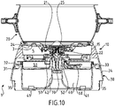
- the electrical cooking appliance 1 can occupy an emptying configuration in which the emptying support 30 carries the cooking assembly 10, as represented on the figure 10 . To achieve this emptying configuration, the user lifts the cooking assembly 10 and places the cooking assembly 10 on the emptying support 30.
- the user has previously placed the cover 50 on the drain support 30.
- the cover 50 is mounted on the drain support 30 carrying the cooking assembly 10
- the lower housing 56 of the cover 50 is then mounted on the rib 36 of the drain support 30.
- the user can leave the cap 60 in the emptying position on the lid 50, as shown in the figure 10 , to leave the passage 51 free, the passage 51 being used for the flow into the emptying receptacle 40 of the cooking bath coming from the emptying device 21.
- the cooking assembly 10 is carried by the emptying support 30.
- the cooking assembly 10 does not necessarily rest directly on the emptying support 30.
- the cooking assembly 10 can in particular rest on the lid 50 resting on the drain support 30.
- control member 70 brings the valve 22 into the open position.
- the positioning of the cooking assembly 10 on the drain support 30 is sufficient to place the valve 22 in the open position.
- the drain receptacle 40 is provided to receive the cooking bath flowing from the valve 22 when the electrical cooking appliance 1 occupies the drain configuration.
- the drain device 21 extends into the passage 51 when the lid 50 is mounted on the drain support 30 and the drain support 30 carries the cooking assembly 10.
- the drain device 21 extends inside the chimney 52 when the lid 50 is mounted on the drain support 30 and the drain support 30 carries the cooking assembly 10, as shown in the figure 10 .
- the control member 70 extends inside the chimney 52 when the lid 50 is mounted on the drain support 30 and the drain support 30 carries the cooking assembly 10.
- the user can remove the entire 10 of the drain support 30 and place the plug 60 in the storage position on the lid 50 to close the passage 51.
- control member 70 is not necessarily formed by a piece attached to the drain support 30, in particular on the drain receptacle 40.
- the control member 70 could in particular be formed integrally with the support drain 30, in particular with the drain receptacle 40.
- control member 70 does not necessarily come from the drain receptacle 40.
- the control member 70 could in particular come from the drain support 30, for example between the zone(s) of support 31 and the drain receptacle 40.
- the control member 70 could also come from the cover 50.
- the drain support 30 carries the cover 50 under the control member 70 or close to the control member 70, so that the control member 70 can move the drain valve 22 while preventing the cover 50 from being subjected to significant forces and/or significant deformations.
- the drain support 30 could in particular have an upper support zone 31, annular or not, or several upper support zones 31, to carry the cooking assembly 10.
- the drain support 30 could in particular have a centering wall 33, annular or not, or several centering walls 33, to center the cooking assembly 10 on the drain support 30.
- the drain support 30 could in particular have a lower support zone 41, annular or not, or several lower support zones 41, to support the cooking assembly 10.
- the zone(s) d The lower support(s) 41 is/are not necessarily arranged under the emptying receptacle 40, but could for example be arranged under the lower skirt 34.
Description
La présente invention concerne le domaine technique des appareils électriques de cuisson comportant une cuve apte à recevoir un bain de cuisson.The present invention relates to the technical field of electrical cooking appliances comprising a tank capable of receiving a cooking bath.
La présente invention concerne plus particulièrement les appareils électriques de cuisson comportant un ensemble de cuisson pouvant être disposé sur un support de vidange.The present invention relates more particularly to electrical cooking appliances comprising a cooking assembly that can be placed on a drain support.
La présente invention concerne notamment, mais non exclusivement, les friteuses.The present invention relates in particular, but not exclusively, to fryers.
Il est connu du document
Un inconvénient de la réalisation précitée réside dans le fait que le couvercle doit être préalablement retiré du support de vidange avant de pouvoir procéder au transfert du bain de cuisson de la cuve dans le réceptacle de vidange via le dispositif de vidange. Lors de la vidange du bain de cuisson des éclaboussures peuvent survenir, ces éclaboussures pouvant atteindre la partie inférieure de l'ensemble de cuisson disposé sur le support de vidange.A disadvantage of the aforementioned embodiment lies in the fact that the lid must be removed beforehand from the drain support before being able to proceed with the transfer of the cooking bath from the tank into the drain receptacle via the drain device. When emptying the cooking bath, splashes may occur, these splashes being able to reach the lower part of the cooking assembly arranged on the drain support.
Un objet de la présente invention est de proposer un appareil électrique de cuisson dont la cuve présente un dispositif de vidange actionné par la mise en place de la cuve sur un support de vidange, dont l'utilisation reste simple tout en assurant une meilleure protection contre les éclaboussures lors de la vidange du contenu de la cuve dans le support de vidange.An object of the present invention is to provide an electrical cooking appliance whose tank has a drain device actuated by placing the tank on a drain support, the use of which remains simple while providing better protection against splashing when emptying the contents of the tank into the drain holder.
Un autre objet de la présente invention est de proposer un appareil électrique de cuisson dont la cuve présente un dispositif de vidange actionné par la mise en place de la cuve sur un support de vidange, dont la construction reste simple tout en assurant une meilleure protection contre les éclaboussures lors de la vidange du contenu de la cuve dans le support de vidange.Another object of the present invention is to provide an electrical cooking appliance whose tank has a drain device actuated by placing the tank on a drain support, the construction of which remains simple while providing better protection against splashing when emptying the contents of the tank into the drain holder.
Ces objets sont atteints avec un appareil électrique de cuisson, notamment friteuse électrique, comportant un ensemble de cuisson, un support de vidange formant un réceptacle de vidange, et un couvercle prévu pour être monté sur le support de vidange, l'appareil électrique de cuisson occupant une configuration de vidange dans laquelle le support de vidange porte l'ensemble de cuisson, l'ensemble de cuisson comprenant une cuve apte à recevoir un bain de cuisson, la cuve étant munie d'un dispositif de vidange comprenant un clapet susceptible d'occuper une position de rappel stable fermée et une position ouverte, un organe de commande amenant le clapet en position ouverte lorsque l'appareil électrique de cuisson occupe la configuration de vidange, du fait que lorsque l'appareil électrique de cuisson occupe la configuration de vidange, le couvercle est monté sur le support de vidange portant l'ensemble de cuisson, le couvercle ménageant un passage pour l'écoulement dans le réceptacle de vidange du bain de cuisson provenant du dispositif de vidange. Ces dispositions permettent de limiter l'ouverture de remplissage du support de vidange lors de la vidange du bain de cuisson dans le réceptacle de vidange. Ces dispositions permettent ainsi de réduire le risque d'éclaboussures hors de l'enceinte formée par le support de vidange et le couvercle.These objects are achieved with an electric cooking appliance, in particular an electric fryer, comprising a cooking assembly, an emptying support forming an emptying receptacle, and a cover provided to be mounted on the emptying support, the electric cooking appliance occupying an emptying configuration in which the emptying support carries the cooking assembly, the cooking assembly comprising a tank capable of receiving a cooking bath, the tank being provided with an emptying device comprising a valve capable of occupy a closed stable return position and an open position, a control member bringing the valve into the open position when the electric cooking appliance occupies the emptying configuration, because when the electric cooking appliance occupies the emptying configuration , the lid is mounted on the drain support carrying the cooking assembly, the lid providing a passage for the flow in the receptacle of vi danger of the cooking bath from the draining device. These provisions make it possible to limit the filling opening of the emptying support during the emptying of the cooking bath into the emptying receptacle. These arrangements thus make it possible to reduce the risk of splashing outside the enclosure formed by the drain support and the cover.
Avantageusement alors, le dispositif de vidange s'étend dans le passage lorsque le couvercle est monté sur le support de vidange et que le support de vidange porte l'ensemble de cuisson. Cette disposition permet que le bain de cuisson s'écoule hors du dispositif de vidange dans l'enceinte formée par le support de vidange et le couvercle.Advantageously then, the emptying device extends into the passage when the lid is mounted on the emptying support and when the emptying support carries the cooking assembly. This arrangement allows the cooking bath to flow out of the drain device into the enclosure formed by the drain support and the lid.
En alternative ou en complément, l'organe de commande peut s'étendre dans le passage lorsque le couvercle est monté sur le support de vidange et que le support de vidange porte l'ensemble de cuisson.Alternatively or in addition, the control member can extend into the passage when the cover is mounted on the drain support and the drain support carries the cooking assembly.
Avantageusement encore, le support de vidange présente une ou plusieurs zone(s) d'appui supérieure(s) portant l'ensemble de cuisson, la ou les zone(s) d'appui supérieure(s) étant agencée(s) autour du couvercle monté sur le support de vidange. Ainsi l'ensemble de cuisson peut reposer sur le support de vidange de manière annulaire autour du couvercle, ou en plusieurs points autour du couvercle. En alternative ou en complément, l'ensemble de cuisson peut reposer sur le couvercle porté par le support de vidange. Ainsi le support de vidange peut porter l'ensemble de cuisson directement ou indirectement.Advantageously, the drain support has one or more upper support zone(s) supporting the cooking assembly, the upper support zone(s) being arranged around the cover mounted on the drain support. Thus the cooking assembly can rest on the emptying support in an annular manner around the cover, or at several points around the cover. Alternatively or in addition, the cooking assembly can rest on the lid carried by the drain support. Thus the drain support can carry the cooking assembly directly or indirectly.
Avantageusement alors, la ou les zone(s) d'appui supérieure(s) est/sont formée(s) autour du réceptacle de vidange. De préférence, la ou les zone(s) d'appui supérieure(s) entoure(nt) le réceptacle de vidange.Advantageously then, the upper support zone(s) is/are formed around the emptying receptacle. Preferably, the upper support zone(s) surround(s) the emptying receptacle.
Avantageusement alors, la ou les zone(s) d'appui supérieure(s) est/sont formée(s) sur une collerette entourant le réceptacle de vidange. Cette disposition permet de rigidifier le support de vidange.Advantageously then, the upper support zone(s) is/are formed on a flange surrounding the emptying receptacle. This arrangement makes it possible to stiffen the drain support.
Avantageusement alors, la collerette présente une ou plusieurs parois de centrage maintenant latéralement l'ensemble de cuisson reposant sur la ou les zone(s) d'appui supérieure(s). Cette disposition permet de stabiliser l'ensemble de cuisson disposé sur le support de vidange.Advantageously then, the flange has one or more centering walls laterally holding the cooking assembly resting on the upper support zone(s). This arrangement makes it possible to stabilize the cooking assembly placed on the emptying support.
Avantageusement encore, la collerette est prolongée par une jupe inférieure entourant le réceptacle de vidange. Cette disposition permet de protéger la paroi latérale du réceptacle de vidange.Advantageously, the flange is extended by a lower skirt surrounding the emptying receptacle. This provision protects the side wall of the drain receptacle.
Avantageusement alors, la jupe inférieure présente des échancrures inférieures. Cette disposition permet de faciliter la manipulation du support de vidange.Advantageously then, the lower skirt has lower notches. This arrangement makes it easier to handle the drain support.
Avantageusement encore, une ou plusieurs zone(s) d'appui inférieure(s) est/sont agencée(s) sous le réceptacle de vidange. Cette disposition permet d'obtenir une surface d'appui inférieure importante.Advantageously, one or more lower support zone(s) is/are arranged under the emptying receptacle. This arrangement makes it possible to obtain a large lower bearing surface.
Avantageusement encore, l'organe de commande est issu du réceptacle de vidange, de préférence du fond du réceptacle de vidange. Cette disposition permet de simplifier la construction du support de vidange et du couvercle. En alternative, l'organe de commande pourrait notamment appartenir au support de vidange sans nécessairement être issu du réceptacle de vidange, ou encore appartenir au couvercle.Advantageously again, the control member comes from the emptying receptacle, preferably from the bottom of the emptying receptacle. This arrangement makes it possible to simplify the construction of the drain support and of the cover. Alternatively, the control member could in particular belong to the drain support without necessarily coming from the drain receptacle, or even belong to the cover.
Avantageusement encore, le couvercle présente une cheminée ménageant le passage. Cette disposition permet de rigidifier le couvercle. Cette disposition permet aussi de mieux exploiter le volume du réceptacle de vidange.Advantageously, the cover has a chimney providing passage. This arrangement makes it possible to stiffen the cover. This arrangement also makes it possible to make better use of the volume of the emptying receptacle.
Avantageusement alors, l'organe de commande s'étend à l'intérieur de la cheminée lorsque le couvercle est monté sur le support de vidange et que le support de vidange porte l'ensemble de cuisson. Cette disposition permet de mieux exploiter le volume du réceptacle de vidange. Cette disposition permet aussi de réduire les risques d'éclaboussures.Advantageously then, the control member extends inside the chimney when the lid is mounted on the drain support and the drain support carries the cooking assembly. This arrangement makes it possible to better exploit the volume of the emptying receptacle. This arrangement also reduces the risk of splashing.
Avantageusement encore, le dispositif de vidange s'étend à l'intérieur de la cheminée lorsque le couvercle est monté sur le support de vidange et que le support de vidange porte l'ensemble de cuisson. Cette disposition permet également de réduire les risques d'éclaboussures.Also advantageously, the drain device extends inside the chimney when the lid is mounted on the drain support and the drain support carries the cooking assembly. This arrangement also reduces the risk of splashing.
Avantageusement encore, l'appareil électrique de cuisson comporte un bouchon prévu pour fermer le passage. Cette disposition permet également d'améliorer la conservation du bain de cuisson dans le support de vidange fermé par le couvercle.Advantageously, the electrical cooking appliance includes a plug provided to close the passage. This arrangement also makes it possible to improve the conservation of the cooking bath in the drain support closed by the lid.
Avantageusement alors, le bouchon est monté mobile sur le couvercle entre une position de vidange dans laquelle le passage est libre et une position de conservation dans laquelle le passage est obturé par le bouchon. Cette disposition permet de simplifier l'utilisation du couvercle.Advantageously then, the stopper is mounted so as to move on the lid between an emptying position in which the passage is free and a storage position in which the passage is closed off by the stopper. This arrangement makes it possible to simplify the use of the cover.
Avantageusement alors, le bouchon est monté pivotant sur le couvercle. Cette disposition permet de simplifier la construction du couvercle.Advantageously then, the plug is pivotally mounted on the cover. This arrangement makes it possible to simplify the construction of the cover.
Avantageusement encore, le bouchon est porté par la cheminée. Cette disposition permet de simplifier la construction du couvercle.Advantageously, the plug is carried by the chimney. This arrangement makes it possible to simplify the construction of the cover.
Avantageusement encore, le couvercle ménage un logement recevant le bouchon en position de vidange lorsque le couvercle est monté sur le support de vidange et que le support de vidange porte l'ensemble de cuisson. Cette disposition permet de réduire l'encombrement de l'appareil.Advantageously, the cover provides a housing receiving the plug in the emptying position when the cover is mounted on the emptying support and when the emptying support carries the cooking assembly. This arrangement makes it possible to reduce the size of the device.
L'invention sera mieux comprise à l'étude d'un exemple de réalisation, pris à titre nullement limitatif, illustré dans les figures annexées, dans lesquelles :
- la
figure 1 est une vue en perspective d'un ensemble de cuisson appartenant à un exemple de réalisation d'un appareil électrique de cuisson selon l'invention, - la
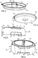
figure 2 est une vue en perspective d'un support de vidange, d'un couvercle et d'un bouchon appartenant à l'appareil électrique de cuisson illustré sur lafigure 1 , le bouchon étant en position de vidange, - la
figure 3 est une vue en perspective latérale du couvercle et du bouchon illustré sur lafigure 2 , le bouchon étant en position de conservation, - la
figure 4 est une vue en perspective de dessous du couvercle illustré sur lesfigures 2 et3 , - la
figure 5 est une vue en élévation du support de vidange illustré sur lafigure 2 , - la
figure 6 est une vue en perspective du support de vidange illustré sur lesfigures 2 et5 , - la
figure 7 est une vue en perspective du support de vidange illustré sur lesfigures 2 ,5 et 6 , selon une autre orientation, - la
figure 8 est une vue de dessous d'un dispositif de vidange appartenant à l'ensemble de cuisson illustré sur lafigure 1 , - la
figure 9 est une vue en perspective d'une partie du couvercle et du bouchon illustrés sur lesfigures 2 ,3 et 4 , le bouchon étant représenté en position de vidange, - la
figure 10 est une vue en élévation et en coupe de l'appareil électrique de cuisson occupant une configuration de vidange dans laquelle le support de vidange illustré sur lafigure 2 porte l'ensemble de cuisson illustré sur lafigure 1 .
- the
figure 1 is a perspective view of a cooking assembly belonging to an embodiment of an electric cooking appliance according to the invention, - the
figure 2 is a perspective view of a drain holder, cover and plug belonging to the electric cooking appliance shown in thefigure 1 , the plug being in the emptying position, - the
picture 3figure 2 , the cap being in the storage position, - the
figure 4 is a bottom perspective view of the cover shown in thefigure 2 and3 , - the
figure 5 is an elevational view of the drain bracket shown in thepicture 2 , - the
figure 6 is a perspective view of the drain bracket shown in thefigure 2 and5 , - the
figure 7 is a perspective view of the drain bracket shown in thefigure 2 ,5 and 6 , according to another orientation, - the
figure 8 is a bottom view of a drain device belonging to the cooking set illustrated in thefigure 1 , - the
figure 9 is a perspective view of part of the lid and cap shown in thefigure 2 ,3 and 4 , the plug being shown in the emptying position, - the
figure 10 is a cross-sectional elevational view of the electrical cooking appliance occupying a drain configuration in which the drain bracket shown in thefigure 2 carries the cooking set illustrated on thefigure 1 .
L'appareil électrique de cuisson 1 illustré sur les
Tel que visible sur les
Le socle de vidange 80 comprend un support de vidange 30, représenté sur les
Le couvercle 50 est prévu pour être monté sur le support de vidange 30, tel qu'illustré sur la
Le couvercle 50 présente une cheminée 52 s'élevant au-dessus d'une paroi d'obturation 54, tel que visible sur la
Le couvercle 50 ménage un passage 51 pour l'écoulement du bain de cuisson dans le support de vidange 30 lorsque le support de vidange 30 porte l'ensemble de cuisson 10. Ainsi lorsque le couvercle 50 est monté sur le support de vidange 30, le couvercle 50 ferme le réceptacle de vidange 40, à l'exception du passage 51. Plus particulièrement dans l'exemple de réalisation illustré sur les figures, la cheminée 52 ménage le passage 51.The
Le bouchon 60 est prévu pour fermer le passage 51. Dans l'exemple de réalisation illustré sur les figures, le bouchon 60 est monté mobile sur le couvercle 50 entre une position de vidange, représentée sur les
Le support de vidange 30 présente plusieurs zones d'appui supérieures 31 prévues pour porter l'ensemble de cuisson 10. Tel que bien visible sur la
Plus particulièrement dans l'exemple de réalisation illustré sur les figures, les zones d'appui supérieures 31 sont formées sur une collerette 32 entourant le réceptacle de vidange 40. Les zones d'appui supérieures 31 sont agencées selon plusieurs niveaux sur la collerette 32. La collerette 32 présente plusieurs parois de centrage 33 prévues pour maintenir latéralement l'ensemble de cuisson 10 reposant sur les zones d'appui supérieures 31. Chaque paroi de centrage 33 est adjacente à l'une des zones d'appui supérieures 31. La collerette 32 est prolongée par une jupe inférieure 34 entourant le réceptacle de vidange 40. La jupe inférieure 34 présente des échancrures inférieures 35. Le support de vidange 30 présente une nervure 36 s'étendant entre la collerette 32 et le réceptacle de vidange 40. La nervure 36 entoure le réceptacle de vidange 40. Ainsi la nervure 36 est annulaire. La nervure 36 forme le bord supérieur du réceptacle de vidange 40.More particularly in the example embodiment illustrated in the figures, the
Le support de vidange 30 présente des zones d'appui inférieures 41. Dans l'exemple de réalisation illustré sur les figures, les zones d'appui inférieures 41 sont agencées sous le réceptacle de vidange 40. Le réceptacle de vidange 40 présente par exemple trois zones d'appui inférieures 41 réparties en périphérie du fond du réceptacle de vidange 40.The emptying
La cuve 20 est munie d'un dispositif de vidange 21, visible sur les
Dans l'exemple de réalisation illustré sur les figures, l'organe de commande 70 est issu du réceptacle de vidange 40, plus particulièrement du fond du réceptacle de vidange 40. Tel que mieux visible sur la
L'appareil électrique de cuisson 1 comporte un dispositif de chauffage électrique 3 associé à la cuve 20. La cuve 20 est assemblée avec l'embase 15 pour former une chambre 5 logeant au moins une partie du dispositif de chauffage électrique 3. Dans l'exemple de réalisation illustré sur les figures, la chambre 5 loge le dispositif de chauffage électrique 3. Tel que mieux visible sur la
L'appareil électrique de cuisson 1 illustré sur les figures fonctionne et s'utilise de la manière suivante.The electrical cooking appliance 1 shown in the figures operates and is used as follows.
L'appareil électrique de cuisson 1 peut occuper une configuration de vidange dans laquelle le support de vidange 30 porte l'ensemble de cuisson 10, tel que représenté sur la
Pour bénéficier des avantages de l'invention, l'utilisateur a préalablement disposé le couvercle 50 sur le support de vidange 30. Ainsi dans la configuration de vidange, le couvercle 50 est monté sur le support de vidange 30 portant l'ensemble de cuisson 10. Le logement inférieur 56 du couvercle 50 est alors monté sur la nervure 36 du support de vidange 30. L'utilisateur peut laisser le bouchon 60 en position de vidange sur le couvercle 50, tel que représenté sur la
Dans la configuration de vidange, l'ensemble de cuisson 10 est porté par le support de vidange 30. Toutefois l'ensemble de cuisson 10 ne repose pas nécessairement directement sur le support de vidange 30. A titre de variante, l'ensemble de cuisson 10 peut notamment reposer sur le couvercle 50 reposant sur le support de vidange 30.In the emptying configuration, the
Dans la configuration de vidange, l'organe de commande 70 amène le clapet 22 en position ouverte. Ainsi le positionnement de l'ensemble de cuisson 10 sur le support de vidange 30 suffit pour placer le clapet 22 en position ouverte.In the emptying configuration, the
Le réceptacle de vidange 40 est prévu pour recevoir le bain de cuisson s'écoulant du clapet 22 lorsque l'appareil électrique de cuisson 1 occupe la configuration de vidange. Dans l'exemple de réalisation illustré sur les figures, le dispositif de vidange 21 s'étend dans le passage 51 lorsque le couvercle 50 est monté sur le support de vidange 30 et que le support de vidange 30 porte l'ensemble de cuisson 10.The
Plus particulièrement, le dispositif de vidange 21 s'étend à l'intérieur de la cheminée 52 lorsque le couvercle 50 est monté sur le support de vidange 30 et que le support de vidange 30 porte l'ensemble de cuisson 10, tel que représenté sur la
Ainsi le bain de cuisson s'écoulant de la cuve 20 par le dispositif de vidange 21 s'écoule dans l'enceinte formée par le couvercle 50 et le réceptacle de vidange 40, ce qui permet de limiter les éclaboussures.Thus the cooking bath flowing from the
Lorsque la vidange a été réalisée, l'utilisateur peut retirer l'ensemble de cuisson 10 du support de vidange 30 et placer le bouchon 60 en position de conservation sur le couvercle 50 pour obturer le passage 51.When emptying has been carried out, the user can remove the entire 10 of the
A titre de variante, l'organe de commande 70 n'est pas nécessairement formé par une pièce rapportée sur le support de vidange 30, notamment sur le réceptacle de vidange 40. L'organe de commande 70 pourrait notamment être formé intégralement avec le support de vidange 30, notamment avec le réceptacle de vidange 40.As a variant, the
A titre de variante, l'organe de commande 70 n'est pas nécessairement issu du réceptacle de vidange 40. L'organe de commande 70 pourrait notamment être issu du support de vidange 30, par exemple entre la ou les zone(s) d'appui supérieures 31 et le réceptacle de vidange 40. L'organe de commande 70 pourrait aussi être issu du couvercle 50. De préférence alors le support de vidange 30 porte le couvercle 50 sous l'organe de commande 70 ou à proximité de l'organe de commande 70, pour que l'organe de commande 70 puisse déplacer le clapet de vidange 22 en évitant que le couvercle 50 soit soumis à des efforts importants et/ou à des déformations importantes.As a variant, the
A titre de variante le support de vidange 30 pourrait notamment présenter une zone d'appui supérieure 31, annulaire ou non, ou plusieurs zones d'appui supérieures 31, pour porter l'ensemble de cuisson 10.As a variant, the
A titre de variante le support de vidange 30 pourrait notamment présenter une paroi de centrage 33, annulaire ou non, ou plusieurs parois de centrage 33, pour centrer l'ensemble de cuisson 10 sur le support de vidange 30.Alternatively, the
A titre de variante le support de vidange 30 pourrait notamment présenter une zone d'appui inférieure 41, annulaire ou non, ou plusieurs zones d'appui inférieures 41, pour porter l'ensemble de cuisson 10. La ou les zone(s) d'appui inférieure(s) 41 n'est/ne sont pas nécessairement agencée(s) sous le réceptacle de vidange 40, mais pourrai(en)t par exemple être agencée(s) sous la jupe inférieure 34.As a variant, the
La présente invention n'est nullement limitée à l'exemple de réalisation décrit et à ses variantes, mais englobe de nombreuses modifications dans le cadre des revendications.The present invention is in no way limited to the embodiment described and its variants, but encompasses numerous modifications within the scope of the claims.
Claims (20)
- Electrical cooking appliance (1), in particular an electric fryer, comprising a cooking assembly (10), a draining support (30) forming a draining receptacle (40), and a lid (50) intended for being mounted on the draining support (30), the electrical cooking appliance (1) adopting a draining configuration in which the draining support (30) supports the cooking assembly (10), the cooking assembly (10) comprising a vessel (20) capable of receiving a cooking bath, the vessel (20) being provided with a draining device (21) comprising a valve (22) capable of adopting a closed stable return position and an open position, a control member (70) moving the valve (22) into the open position when the electrical cooking appliance (1) adopts the draining configuration, characterised in that when the electrical cooking appliance (1) adopts the draining configuration, the lid (50) is mounted on the draining support (30) supporting the cooking assembly (10), the lid (50) providing a passage (51) for the flow into the draining receptacle (40) of the cooking bath coming from the draining device (21).
- Electrical cooking appliance (1) according to claim 1, characterised in that the cooking assembly (10) comprises a base (15) arranged under a lower part (24) of the vessel (20) and in that when the electrical cooking appliance (1) adopts the draining configuration, the lid (50) is mounted on the draining support (30) supporting the base (15) of the cooking assembly (10).
- Electrical cooking appliance (1) according to one of claims 1 or 2, characterised in that when the lid (50) is mounted on the draining support (30), the lid (50) closes the draining receptacle (40), except for the passage (51).
- Electrical cooking appliance (1) according to one of claims 1 to 3, characterised in that the draining device (21) extends into the passage (51) when the lid (50) is mounted on the draining support (30) and the draining support (30) supports the cooking assembly (10).
- Electrical cooking appliance (1) according to one of claims 1 to 4, characterised in that the draining support (30) has one or more upper support zone(s) (31) supporting the cooking assembly (10), and in that the upper support zone(s) (31) is/are arranged around the lid (50) mounted on the draining support (30).
- Electrical cooking appliance (1) according to claim 5, characterised in that the upper support zone(s) (31) is/are formed around the draining receptacle (40).
- Electrical cooking appliance (1) according to claim 6, characterised in that the upper support zone(s) (31) is/are formed on a collar (32) surrounding the draining receptacle (40).
- Electrical cooking appliance (1) according to claim 7, characterised in that the collar (32) has one or more centring wall(s) (33) laterally holding the cooking assembly (10) resting on the upper support zone(s) (31).
- Electrical cooking appliance (1) according to one of claims 7 or 8, characterised in that the collar (32) is extended by a lower skirt (34) surrounding the draining receptacle (40).
- Electrical cooking appliance (1) according to claim 9, characterised in that the lower skirt (34) has lower indentations (35).
- Electrical cooking appliance (1) according to one of claims 1 to 10, characterised in that one or more lower support zone(s) (41) is/are arranged under the draining receptacle (40).
- Electrical cooking appliance (1) according to one of claims 1 to 11, characterised in that the control member (70) comes from the draining receptacle (40), preferably from the bottom of the draining receptacle (40).
- Electrical cooking appliance (1) according to one of claims 1 to 12, characterised in that the lid (50) has a funnel (52) providing the passage (51).
- Electrical cooking appliance (1) according to claim 13, characterised in that the control member (70) extends inside the funnel (52) when the lid (50) is mounted on the draining support (30) and that the draining support (30) supports the cooking assembly (10).
- Electrical cooking appliance (1) according to one of claims 13 or 14, characterised in that the draining device (21) extends inside the funnel (52) when the lid (50) is mounted on the draining support (30) and that the draining support (30) supports the cooking assembly (10).
- Electrical cooking appliance (1) according to one of claims 1 to 15, characterised in that it comprises a stopper (60) provided to close the passage (51).
- Electrical cooking appliance (1) according to claim 16, characterised in that the stopper (60) is mounted on the lid (50) to be movable between a draining position in which the passage (51) is free and a preservation position in which the passage (51) is blocked by the stopper (60).
- Electrical cooking appliance (1) according to claim 17, characterised in that the stopper (60) is mounted to be pivoted on the lid (50).
- Electrical cooking appliance (1) according to one of claims 17 or 18, characterised in that the stopper (60) is supported by the funnel (52).
- Electrical cooking appliance (1) according to one of claims 17 to 19, characterised in that the lid (50) provides a housing (53) receiving the stopper (60) in the draining position when the lid (50) is mounted on the draining support (30) and when the draining support (30) supports the cooking assembly (10).
Applications Claiming Priority (2)
| Application Number | Priority Date | Filing Date | Title |
|---|---|---|---|
| FR1759688A FR3072263B1 (en) | 2017-10-16 | 2017-10-16 | ELECTRIC COOKING APPARATUS COMPRISING A DRAIN SUPPORT WITH A COVER |
| PCT/FR2018/052545 WO2019077242A1 (en) | 2017-10-16 | 2018-10-12 | Electrical cooking appliance having an draining support with a lid |
Publications (2)
| Publication Number | Publication Date |
|---|---|
| EP3697276A1 EP3697276A1 (en) | 2020-08-26 |
| EP3697276B1 true EP3697276B1 (en) | 2022-04-13 |
Family
ID=60955216
Family Applications (1)
| Application Number | Title | Priority Date | Filing Date |
|---|---|---|---|
| EP18803737.8A Active EP3697276B1 (en) | 2017-10-16 | 2018-10-12 | Electrical cooking appliance having a draining support with a lid |
Country Status (8)
| Country | Link |
|---|---|
| US (1) | US11000144B2 (en) |
| EP (1) | EP3697276B1 (en) |
| CN (2) | CN210008865U (en) |
| AU (1) | AU2018350951B2 (en) |
| CA (1) | CA3078712C (en) |
| ES (1) | ES2912731T3 (en) |
| FR (1) | FR3072263B1 (en) |
| WO (1) | WO2019077242A1 (en) |
Families Citing this family (1)
| Publication number | Priority date | Publication date | Assignee | Title |
|---|---|---|---|---|
| FR3110832B1 (en) * | 2020-05-28 | 2022-04-22 | Seb Sa | COOKING SET COMPRISING AN ELECTRIC COOKING APPLIANCE AND A DRAIN BASE |
Citations (2)
| Publication number | Priority date | Publication date | Assignee | Title |
|---|---|---|---|---|
| EP1504705B1 (en) * | 2003-08-05 | 2007-06-27 | Seb S.A. | Electrical cooking appliance containing a drain base |
| EP2103240B1 (en) * | 2008-03-20 | 2012-05-30 | Seb S.A. | Electrical cooking device comprising an electrical supply and drainage base |
Family Cites Families (7)
| Publication number | Priority date | Publication date | Assignee | Title |
|---|---|---|---|---|
| US6327965B1 (en) * | 2000-07-03 | 2001-12-11 | Yu-Mei Lin Tien | Safety and drain-preventing infusing tea maker |
| FR2830734B1 (en) * | 2001-10-17 | 2004-02-06 | Seb Sa | TANK COOKING APPARATUS HAVING A SECURE DRAINING DEVICE |
| US9839230B2 (en) * | 2011-03-31 | 2017-12-12 | Raymond L. Neff | Device for defrosting, warming and cooking using a circulating fluid |
| FR2999403B1 (en) * | 2012-12-19 | 2015-01-02 | Seb Sa | CULINARY PREPARATION ELECTRICAL APPLIANCE COMPRISING A WORKING CONTAINER AND A DEVICE FOR HEATING THE CONTENTS OF THE WORK CONTAINER |
| FR3034300B1 (en) * | 2015-04-01 | 2017-09-15 | Seb Sa | CULINARY PREPARATION ELECTRICAL APPLIANCE COMPRISING A COVER WITH A CHIMNEY FOR THE INTRODUCTION OF FOOD |
| US11589700B2 (en) * | 2015-11-09 | 2023-02-28 | Conair Llc | Food steamer |
| FR3060288B1 (en) * | 2016-12-20 | 2019-05-31 | Seb S.A. | STEAM COOKER COMPRISING A CONTAINER AND AN ACCESSORY FOR HEATING AND / OR STEAMING THE FOODS CONTAINED IN THE CONTAINER |
-
2017
- 2017-10-16 FR FR1759688A patent/FR3072263B1/en active Active
-
2018
- 2018-10-12 EP EP18803737.8A patent/EP3697276B1/en active Active
- 2018-10-12 CA CA3078712A patent/CA3078712C/en active Active
- 2018-10-12 WO PCT/FR2018/052545 patent/WO2019077242A1/en unknown
- 2018-10-12 US US16/756,412 patent/US11000144B2/en active Active
- 2018-10-12 AU AU2018350951A patent/AU2018350951B2/en active Active
- 2018-10-12 ES ES18803737T patent/ES2912731T3/en active Active
- 2018-10-16 CN CN201821674194.3U patent/CN210008865U/en active Active
- 2018-10-16 CN CN201811202760.5A patent/CN109662558B/en active Active
Patent Citations (2)
| Publication number | Priority date | Publication date | Assignee | Title |
|---|---|---|---|---|
| EP1504705B1 (en) * | 2003-08-05 | 2007-06-27 | Seb S.A. | Electrical cooking appliance containing a drain base |
| EP2103240B1 (en) * | 2008-03-20 | 2012-05-30 | Seb S.A. | Electrical cooking device comprising an electrical supply and drainage base |
Also Published As
| Publication number | Publication date |
|---|---|
| CN210008865U (en) | 2020-02-04 |
| AU2018350951A1 (en) | 2020-06-04 |
| FR3072263A1 (en) | 2019-04-19 |
| WO2019077242A1 (en) | 2019-04-25 |
| EP3697276A1 (en) | 2020-08-26 |
| CA3078712C (en) | 2021-09-14 |
| CN109662558A (en) | 2019-04-23 |
| CN109662558B (en) | 2021-11-12 |
| ES2912731T3 (en) | 2022-05-27 |
| US11000144B2 (en) | 2021-05-11 |
| US20200315388A1 (en) | 2020-10-08 |
| CA3078712A1 (en) | 2019-04-25 |
| AU2018350951B2 (en) | 2021-03-25 |
| FR3072263B1 (en) | 2019-11-08 |
Similar Documents
| Publication | Publication Date | Title |
|---|---|---|
| EP3558071B1 (en) | Modular steamer accessory for steam-heating and/or -cooking food contained in a container | |
| EP2103240B1 (en) | Electrical cooking device comprising an electrical supply and drainage base | |
| FR3037493A1 (en) | VAPOR COOKING ACCESSORIES FOR HEATING AND / OR STEAMING FOODS CONTAINED IN A CONTAINER | |
| EP3697276B1 (en) | Electrical cooking appliance having a draining support with a lid | |
| EP1504705B1 (en) | Electrical cooking appliance containing a drain base | |
| EP3697275B1 (en) | Electrical cooking appliance comprising a draining support with a storage configuration | |
| EP2436289B1 (en) | Electrical cooking appliance comprising a hinged lid provided with a condensate-recovery device | |
| EP2574259B1 (en) | Steam cooker with device for filling the water tank during cooking | |
| FR2822363A1 (en) | Electric cooker with exterior connection has pot to receive liquid mounted in casing with external power connection having condensate deflection guide | |
| EP1504706B1 (en) | Electrical cooking appliance with an electrical power supply base | |
| EP1651086B1 (en) | Cooking container for a heating base or an electric base | |
| EP3886660B1 (en) | Cooking assembly comprising an electrical cooking appliance and a draining receptacle | |
| EP3659477B1 (en) | Stackable drainage base for an electric cooking appliance | |
| FR2830736A1 (en) | Cooking appliance such as deep fryer has drain outlet with thermostatic valve to avoid risk of burns | |
| CA3121306A1 (en) | Cooking assembly comprising an electrical cooking appliance and a draining base | |
| EP1736083A1 (en) | Cooker with anti-foaming device | |
| FR3110832A1 (en) | COOKING KIT INCLUDING AN ELECTRIC COOKING APPLIANCE AND A DRAIN BASE | |
| FR2858533A1 (en) | Electrical cooking apparatus e.g. deep fryer, has control unit provided in base to bring spring valve of draining device in open position when case is positioned in place for draining bath of cooking |
Legal Events
| Date | Code | Title | Description |
|---|---|---|---|
| STAA | Information on the status of an ep patent application or granted ep patent |
Free format text: STATUS: UNKNOWN |
|
| STAA | Information on the status of an ep patent application or granted ep patent |
Free format text: STATUS: THE INTERNATIONAL PUBLICATION HAS BEEN MADE |
|
| PUAI | Public reference made under article 153(3) epc to a published international application that has entered the european phase |
Free format text: ORIGINAL CODE: 0009012 |
|
| STAA | Information on the status of an ep patent application or granted ep patent |
Free format text: STATUS: REQUEST FOR EXAMINATION WAS MADE |
|
| 17P | Request for examination filed |
Effective date: 20200511 |
|
| AK | Designated contracting states |
Kind code of ref document: A1 Designated state(s): AL AT BE BG CH CY CZ DE DK EE ES FI FR GB GR HR HU IE IS IT LI LT LU LV MC MK MT NL NO PL PT RO RS SE SI SK SM TR |
|
| AX | Request for extension of the european patent |
Extension state: BA ME |
|
| DAV | Request for validation of the european patent (deleted) | ||
| DAX | Request for extension of the european patent (deleted) | ||
| GRAP | Despatch of communication of intention to grant a patent |
Free format text: ORIGINAL CODE: EPIDOSNIGR1 |
|
| STAA | Information on the status of an ep patent application or granted ep patent |
Free format text: STATUS: GRANT OF PATENT IS INTENDED |
|
| INTG | Intention to grant announced |
Effective date: 20210611 |
|
| RIN1 | Information on inventor provided before grant (corrected) |
Inventor name: DIRAND, PASCAL Inventor name: SARTOUT, PIERRE Inventor name: SEURAT, FREDERIC |
|
| GRAJ | Information related to disapproval of communication of intention to grant by the applicant or resumption of examination proceedings by the epo deleted |
Free format text: ORIGINAL CODE: EPIDOSDIGR1 |
|
| STAA | Information on the status of an ep patent application or granted ep patent |
Free format text: STATUS: REQUEST FOR EXAMINATION WAS MADE |
|
| GRAP | Despatch of communication of intention to grant a patent |
Free format text: ORIGINAL CODE: EPIDOSNIGR1 |
|
| STAA | Information on the status of an ep patent application or granted ep patent |
Free format text: STATUS: GRANT OF PATENT IS INTENDED |
|
| INTC | Intention to grant announced (deleted) | ||
| INTG | Intention to grant announced |
Effective date: 20211103 |
|
| GRAS | Grant fee paid |
Free format text: ORIGINAL CODE: EPIDOSNIGR3 |
|
| GRAA | (expected) grant |
Free format text: ORIGINAL CODE: 0009210 |
|
| STAA | Information on the status of an ep patent application or granted ep patent |
Free format text: STATUS: THE PATENT HAS BEEN GRANTED |
|
| AK | Designated contracting states |
Kind code of ref document: B1 Designated state(s): AL AT BE BG CH CY CZ DE DK EE ES FI FR GB GR HR HU IE IS IT LI LT LU LV MC MK MT NL NO PL PT RO RS SE SI SK SM TR |
|
| REG | Reference to a national code |
Ref country code: GB Ref legal event code: FG4D Free format text: NOT ENGLISH |
|
| REG | Reference to a national code |
Ref country code: CH Ref legal event code: EP |
|
| REG | Reference to a national code |
Ref country code: DE Ref legal event code: R096 Ref document number: 602018033869 Country of ref document: DE |
|
| REG | Reference to a national code |
Ref country code: IE Ref legal event code: FG4D Free format text: LANGUAGE OF EP DOCUMENT: FRENCH |
|
| REG | Reference to a national code |
Ref country code: AT Ref legal event code: REF Ref document number: 1482728 Country of ref document: AT Kind code of ref document: T Effective date: 20220515 |
|
| REG | Reference to a national code |
Ref country code: LT Ref legal event code: MG9D |
|
| REG | Reference to a national code |
Ref country code: NL Ref legal event code: MP Effective date: 20220413 |
|
| REG | Reference to a national code |
Ref country code: AT Ref legal event code: MK05 Ref document number: 1482728 Country of ref document: AT Kind code of ref document: T Effective date: 20220413 |
|
| PG25 | Lapsed in a contracting state [announced via postgrant information from national office to epo] |
Ref country code: NL Free format text: LAPSE BECAUSE OF FAILURE TO SUBMIT A TRANSLATION OF THE DESCRIPTION OR TO PAY THE FEE WITHIN THE PRESCRIBED TIME-LIMIT Effective date: 20220413 |
|
| PG25 | Lapsed in a contracting state [announced via postgrant information from national office to epo] |
Ref country code: SE Free format text: LAPSE BECAUSE OF FAILURE TO SUBMIT A TRANSLATION OF THE DESCRIPTION OR TO PAY THE FEE WITHIN THE PRESCRIBED TIME-LIMIT Effective date: 20220413 Ref country code: PT Free format text: LAPSE BECAUSE OF FAILURE TO SUBMIT A TRANSLATION OF THE DESCRIPTION OR TO PAY THE FEE WITHIN THE PRESCRIBED TIME-LIMIT Effective date: 20220816 Ref country code: NO Free format text: LAPSE BECAUSE OF FAILURE TO SUBMIT A TRANSLATION OF THE DESCRIPTION OR TO PAY THE FEE WITHIN THE PRESCRIBED TIME-LIMIT Effective date: 20220713 Ref country code: LT Free format text: LAPSE BECAUSE OF FAILURE TO SUBMIT A TRANSLATION OF THE DESCRIPTION OR TO PAY THE FEE WITHIN THE PRESCRIBED TIME-LIMIT Effective date: 20220413 Ref country code: HR Free format text: LAPSE BECAUSE OF FAILURE TO SUBMIT A TRANSLATION OF THE DESCRIPTION OR TO PAY THE FEE WITHIN THE PRESCRIBED TIME-LIMIT Effective date: 20220413 Ref country code: GR Free format text: LAPSE BECAUSE OF FAILURE TO SUBMIT A TRANSLATION OF THE DESCRIPTION OR TO PAY THE FEE WITHIN THE PRESCRIBED TIME-LIMIT Effective date: 20220714 Ref country code: FI Free format text: LAPSE BECAUSE OF FAILURE TO SUBMIT A TRANSLATION OF THE DESCRIPTION OR TO PAY THE FEE WITHIN THE PRESCRIBED TIME-LIMIT Effective date: 20220413 Ref country code: BG Free format text: LAPSE BECAUSE OF FAILURE TO SUBMIT A TRANSLATION OF THE DESCRIPTION OR TO PAY THE FEE WITHIN THE PRESCRIBED TIME-LIMIT Effective date: 20220713 Ref country code: AT Free format text: LAPSE BECAUSE OF FAILURE TO SUBMIT A TRANSLATION OF THE DESCRIPTION OR TO PAY THE FEE WITHIN THE PRESCRIBED TIME-LIMIT Effective date: 20220413 |
|
| PG25 | Lapsed in a contracting state [announced via postgrant information from national office to epo] |
Ref country code: RS Free format text: LAPSE BECAUSE OF FAILURE TO SUBMIT A TRANSLATION OF THE DESCRIPTION OR TO PAY THE FEE WITHIN THE PRESCRIBED TIME-LIMIT Effective date: 20220413 Ref country code: PL Free format text: LAPSE BECAUSE OF FAILURE TO SUBMIT A TRANSLATION OF THE DESCRIPTION OR TO PAY THE FEE WITHIN THE PRESCRIBED TIME-LIMIT Effective date: 20220413 Ref country code: LV Free format text: LAPSE BECAUSE OF FAILURE TO SUBMIT A TRANSLATION OF THE DESCRIPTION OR TO PAY THE FEE WITHIN THE PRESCRIBED TIME-LIMIT Effective date: 20220413 Ref country code: IS Free format text: LAPSE BECAUSE OF FAILURE TO SUBMIT A TRANSLATION OF THE DESCRIPTION OR TO PAY THE FEE WITHIN THE PRESCRIBED TIME-LIMIT Effective date: 20220813 |
|
| REG | Reference to a national code |
Ref country code: DE Ref legal event code: R097 Ref document number: 602018033869 Country of ref document: DE |
|
| PG25 | Lapsed in a contracting state [announced via postgrant information from national office to epo] |
Ref country code: SM Free format text: LAPSE BECAUSE OF FAILURE TO SUBMIT A TRANSLATION OF THE DESCRIPTION OR TO PAY THE FEE WITHIN THE PRESCRIBED TIME-LIMIT Effective date: 20220413 Ref country code: SK Free format text: LAPSE BECAUSE OF FAILURE TO SUBMIT A TRANSLATION OF THE DESCRIPTION OR TO PAY THE FEE WITHIN THE PRESCRIBED TIME-LIMIT Effective date: 20220413 Ref country code: RO Free format text: LAPSE BECAUSE OF FAILURE TO SUBMIT A TRANSLATION OF THE DESCRIPTION OR TO PAY THE FEE WITHIN THE PRESCRIBED TIME-LIMIT Effective date: 20220413 Ref country code: EE Free format text: LAPSE BECAUSE OF FAILURE TO SUBMIT A TRANSLATION OF THE DESCRIPTION OR TO PAY THE FEE WITHIN THE PRESCRIBED TIME-LIMIT Effective date: 20220413 Ref country code: DK Free format text: LAPSE BECAUSE OF FAILURE TO SUBMIT A TRANSLATION OF THE DESCRIPTION OR TO PAY THE FEE WITHIN THE PRESCRIBED TIME-LIMIT Effective date: 20220413 Ref country code: CZ Free format text: LAPSE BECAUSE OF FAILURE TO SUBMIT A TRANSLATION OF THE DESCRIPTION OR TO PAY THE FEE WITHIN THE PRESCRIBED TIME-LIMIT Effective date: 20220413 |
|
| PLBE | No opposition filed within time limit |
Free format text: ORIGINAL CODE: 0009261 |
|
| STAA | Information on the status of an ep patent application or granted ep patent |
Free format text: STATUS: NO OPPOSITION FILED WITHIN TIME LIMIT |
|
| 26N | No opposition filed |
Effective date: 20230116 |
|
| PG25 | Lapsed in a contracting state [announced via postgrant information from national office to epo] |
Ref country code: AL Free format text: LAPSE BECAUSE OF FAILURE TO SUBMIT A TRANSLATION OF THE DESCRIPTION OR TO PAY THE FEE WITHIN THE PRESCRIBED TIME-LIMIT Effective date: 20220413 |
|
| PG25 | Lapsed in a contracting state [announced via postgrant information from national office to epo] |
Ref country code: SI Free format text: LAPSE BECAUSE OF FAILURE TO SUBMIT A TRANSLATION OF THE DESCRIPTION OR TO PAY THE FEE WITHIN THE PRESCRIBED TIME-LIMIT Effective date: 20220413 Ref country code: MC Free format text: LAPSE BECAUSE OF FAILURE TO SUBMIT A TRANSLATION OF THE DESCRIPTION OR TO PAY THE FEE WITHIN THE PRESCRIBED TIME-LIMIT Effective date: 20220413 |
|
| REG | Reference to a national code |
Ref country code: CH Ref legal event code: PL |
|
| P01 | Opt-out of the competence of the unified patent court (upc) registered |
Effective date: 20230517 |
|
| REG | Reference to a national code |
Ref country code: BE Ref legal event code: MM Effective date: 20221031 |
|
| PG25 | Lapsed in a contracting state [announced via postgrant information from national office to epo] |
Ref country code: LU Free format text: LAPSE BECAUSE OF NON-PAYMENT OF DUE FEES Effective date: 20221012 |
|
| PG25 | Lapsed in a contracting state [announced via postgrant information from national office to epo] |
Ref country code: LI Free format text: LAPSE BECAUSE OF NON-PAYMENT OF DUE FEES Effective date: 20221031 Ref country code: CH Free format text: LAPSE BECAUSE OF NON-PAYMENT OF DUE FEES Effective date: 20221031 |
|
| PG25 | Lapsed in a contracting state [announced via postgrant information from national office to epo] |
Ref country code: BE Free format text: LAPSE BECAUSE OF NON-PAYMENT OF DUE FEES Effective date: 20221031 |
|
| PG25 | Lapsed in a contracting state [announced via postgrant information from national office to epo] |
Ref country code: IE Free format text: LAPSE BECAUSE OF NON-PAYMENT OF DUE FEES Effective date: 20221012 |
|
| PGFP | Annual fee paid to national office [announced via postgrant information from national office to epo] |
Ref country code: GB Payment date: 20231019 Year of fee payment: 6 |
|
| PGFP | Annual fee paid to national office [announced via postgrant information from national office to epo] |
Ref country code: ES Payment date: 20231114 Year of fee payment: 6 |
|
| PG25 | Lapsed in a contracting state [announced via postgrant information from national office to epo] |
Ref country code: IT Free format text: LAPSE BECAUSE OF FAILURE TO SUBMIT A TRANSLATION OF THE DESCRIPTION OR TO PAY THE FEE WITHIN THE PRESCRIBED TIME-LIMIT Effective date: 20220413 |
|
| PGFP | Annual fee paid to national office [announced via postgrant information from national office to epo] |
Ref country code: FR Payment date: 20231023 Year of fee payment: 6 Ref country code: DE Payment date: 20231011 Year of fee payment: 6 |