EP3697111A1 - System, vehicle, apparatuses, methods, and computer programs for user equipment and for a base station in a mobile communication system - Google Patents
System, vehicle, apparatuses, methods, and computer programs for user equipment and for a base station in a mobile communication system Download PDFInfo
- Publication number
- EP3697111A1 EP3697111A1 EP19157421.9A EP19157421A EP3697111A1 EP 3697111 A1 EP3697111 A1 EP 3697111A1 EP 19157421 A EP19157421 A EP 19157421A EP 3697111 A1 EP3697111 A1 EP 3697111A1
- Authority
- EP
- European Patent Office
- Prior art keywords
- group
- message
- ues
- mobile communication
- communication system
- Prior art date
- Legal status (The legal status is an assumption and is not a legal conclusion. Google has not performed a legal analysis and makes no representation as to the accuracy of the status listed.)
- Pending
Links
Images


Classifications
-
- H—ELECTRICITY
- H04—ELECTRIC COMMUNICATION TECHNIQUE
- H04W—WIRELESS COMMUNICATION NETWORKS
- H04W4/00—Services specially adapted for wireless communication networks; Facilities therefor
- H04W4/06—Selective distribution of broadcast services, e.g. multimedia broadcast multicast service [MBMS]; Services to user groups; One-way selective calling services
- H04W4/08—User group management
-
- H—ELECTRICITY
- H04—ELECTRIC COMMUNICATION TECHNIQUE
- H04W—WIRELESS COMMUNICATION NETWORKS
- H04W4/00—Services specially adapted for wireless communication networks; Facilities therefor
- H04W4/30—Services specially adapted for particular environments, situations or purposes
- H04W4/40—Services specially adapted for particular environments, situations or purposes for vehicles, e.g. vehicle-to-pedestrians [V2P]
-
- H—ELECTRICITY
- H04—ELECTRIC COMMUNICATION TECHNIQUE
- H04W—WIRELESS COMMUNICATION NETWORKS
- H04W40/00—Communication routing or communication path finding
- H04W40/02—Communication route or path selection, e.g. power-based or shortest path routing
- H04W40/22—Communication route or path selection, e.g. power-based or shortest path routing using selective relaying for reaching a BTS [Base Transceiver Station] or an access point
-
- H—ELECTRICITY
- H04—ELECTRIC COMMUNICATION TECHNIQUE
- H04W—WIRELESS COMMUNICATION NETWORKS
- H04W72/00—Local resource management
- H04W72/12—Wireless traffic scheduling
- H04W72/121—Wireless traffic scheduling for groups of terminals or users
-
- H—ELECTRICITY
- H04—ELECTRIC COMMUNICATION TECHNIQUE
- H04W—WIRELESS COMMUNICATION NETWORKS
- H04W8/00—Network data management
- H04W8/005—Discovery of network devices, e.g. terminals
-
- H—ELECTRICITY
- H04—ELECTRIC COMMUNICATION TECHNIQUE
- H04W—WIRELESS COMMUNICATION NETWORKS
- H04W84/00—Network topologies
- H04W84/02—Hierarchically pre-organised networks, e.g. paging networks, cellular networks, WLAN [Wireless Local Area Network] or WLL [Wireless Local Loop]
- H04W84/04—Large scale networks; Deep hierarchical networks
- H04W84/042—Public Land Mobile systems, e.g. cellular systems
- H04W84/047—Public Land Mobile systems, e.g. cellular systems using dedicated repeater stations
-
- H—ELECTRICITY
- H04—ELECTRIC COMMUNICATION TECHNIQUE
- H04W—WIRELESS COMMUNICATION NETWORKS
- H04W88/00—Devices specially adapted for wireless communication networks, e.g. terminals, base stations or access point devices
- H04W88/02—Terminal devices
- H04W88/04—Terminal devices adapted for relaying to or from another terminal or user
-
- H—ELECTRICITY
- H04—ELECTRIC COMMUNICATION TECHNIQUE
- H04W—WIRELESS COMMUNICATION NETWORKS
- H04W88/00—Devices specially adapted for wireless communication networks, e.g. terminals, base stations or access point devices
- H04W88/08—Access point devices
-
- H—ELECTRICITY
- H04—ELECTRIC COMMUNICATION TECHNIQUE
- H04W—WIRELESS COMMUNICATION NETWORKS
- H04W92/00—Interfaces specially adapted for wireless communication networks
- H04W92/16—Interfaces between hierarchically similar devices
- H04W92/18—Interfaces between hierarchically similar devices between terminal devices
Definitions
- the present invention relates to a system, a vehicle, apparatuses, methods, and computer programs for user equipment, UE, and a base station in a mobile communication system, more particularly, but not exclusively, to a concept for transmitting a unicast message to a group of UEs for further relaying in an out-of-coverage situation.
- Document US 2018/0077518 A1 describes a concept for sharing sensor data among vehicles. Common information is broadcast to nearby vehicles. Based on the common information some vehicles may request more detailed information. Unicast and/or multicast sessions may be set up to share the detailed information.
- Document WO 2017/075920 A1 discloses a data transmission method and device for vehicle communications, base station, and network side device. The data transmission method determines, according to a number of receiving terminals receiving the vehicle communication data or according to instruction information sent by the sending terminal, whether to use a unicast mode or a broadcast mode to transmit the vehicle communication data. If a broadcast mode is determined to be used to transmit the vehicle communication data, then a range where the vehicle communication data needs to be broadcast is determined.
- R2-1818728 is a 3GPP (3rd Generation Partnership Project) meeting contribution relating to unicast, groupcast, and broadcast support for in-coverage, out-of-coverage, and partial coverage scenarios.
- Embodiments are based on the finding that UEs can be organized in groups for group communication and that the UEs within such a group may experience different coverage scenarios. It is a further finding that a UE being out-of-coverage, OOC, of a base station may still communicate with such a base station through one or more other UEs, which are in the same group and in coverage of the base station.
- the OOC-UE may broadcast or multicast a message, which is actually a unicast message, to the group of UEs, and group members may then forward the message.
- Embodiments provide a method for user equipment, UE, in a mobile communication system.
- the method comprises determining a coverage situation of the mobile communication system, forming a group of multiple UEs, and communicating a unicast message to multiple UEs of the group of UEs based on the coverage situation of the mobile communication system.
- a reliability or robustness of wireless communication may be increased by communicating a unicast message to multiple UEs.
- Embodiments may enable an enhanced uplink communication in a mobile communication system.
- the communicating of the unicast message directed to the multiple UEs of the group of UEs may be carried out if the UE is out of coverage of a base station of the mobile communication system in some embodiments. Coverage of a base station may be enhanced by using group communication.
- the unicast message directed to multiple UEs of the group of UEs may be comprised in or wrapped into a multicast or broadcast message.
- the forming of the group of UEs may comprise assigning a group or groupcast identification to the group of UEs.
- the method may further comprise using the group identification or a groupcast identification to address the unicast message to the group of UEs.
- Embodiments may enable a simple and efficient mechanism to enhance coverage in a mobile communication system using direct communication between UEs.
- the forming of the group of UEs may comprise determining group members based on a common geographic path or location of the UEs.
- Embodiments may form groups or clusters of co-allocated UEs or UEs sharing the same route. Such grouping or clustering may further contribute to enhance communication efficiency.
- the determining of the coverage situation may comprise looking up coverage information in a coverage map based on a location of the UE. Coverage maps may contribute to a simple and efficient way of distinguishing areas with different coverage qualities/situations. Additionally or alternatively, the determining of the coverage situation may comprise measuring a signal from the mobile communication system, wherein the signal is indicative of the coverage of the mobile communication system. Coverage measurements may help determining an up-to-date coverage situation at certain location, even when the network infrastructure changes (for example added base stations/cells).
- the method may, in some further embodiments, comprise receiving a message, which is addressing multiple UEs, from another UE.
- the method may further comprise determining whether the message is a unicast message, which was transmitted to multiple UEs, and relaying the message if it is a unicast message, which was transmitted to multiple UEs.
- UEs may be configured to relay such messages in order to eventually transmit the message to its dedicated receiver.
- the relaying may comprise relaying the unicast message to another UE, to a base station of the mobile communication system, or to the group of UEs.
- UEs may establish an adaptive and dynamic adhoc network component.
- Embodiments further provide a method for user equipment, UE, in a mobile communication system.
- the method comprises receiving a message, which is addressing multiple UEs, from another UE, determining whether the message is a unicast message, which was transmitted to multiple UEs, and relaying the message if it is a unicast message, which was transmitted to multiple UEs.
- UEs may therewith be enabled to form a multi-hop or adhoc network component, even if they are not capable of transmitting a unicast message to multiple UEs.
- the relaying may comprise relaying the unicast message to another UE, to a base station of the mobile communication system, or to the group of UEs.
- An apparatus for user equipment, UE, in a mobile communication system is another embodiment.
- the apparatus comprises one or more interfaces, which are configured to communicate in the mobile communication system.
- the apparatus further comprises a control module, which is configured to control the one or more interfaces.
- the control module is further configured to perform one of the methods described herein.
- Another embodiment is a method for a base station in a mobile communication system.
- the method comprises determining an out-of-coverage situation for user equipment, UE, to which a message is to be sent.
- the method further comprises determining an identification of a group of multiple UEs the UE is assigned to.
- the method further comprises transmitting the message to the group of UEs for relaying to the UE.
- Embodiments may also enable to use an adhoc or multi-hop network component in the downlink.
- the method may further comprise receiving an acknowledgment message for the message from a UE of the group.
- Embodiments may use the adhoc or multi-hop component for receiving acknowledgements for transmitted messages or data packets.
- Embodiments also provide an apparatus for a base station in a mobile communication system.
- the apparatus comprises one or more interfaces, which are configured to communicate in the mobile communication system.
- the apparatus further comprises a control module, which is configured to control the one or more interfaces.
- the control module is further configured to perform one of the methods described herein.
- a further embodiment is a vehicle comprising one of the apparatuses described herein.
- Embodiments further provide a computer program having a program code for performing one or more of the above described methods, when the computer program is executed on a computer, processor, or programmable hardware component.
- a further embodiment is a computer readable storage medium storing instructions which, when executed by a computer, processor, or programmable hardware component, cause the computer to implement one of the methods described herein.
- the term “or” refers to a non-exclusive or, unless otherwise indicated (e.g., “or else” or “or in the alternative”).
- words used to describe a relationship between elements should be broadly construed to include a direct relationship or the presence of intervening elements unless otherwise indicated. For example, when an element is referred to as being “connected” or “coupled” to another element, the element may be directly connected or coupled to the other element or intervening elements may be present. In contrast, when an element is referred to as being “directly connected” or “directly coupled” to another element, there are no intervening elements present. Similarly, words such as “between”, “adjacent”, and the like should be interpreted in a like fashion.
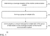
- Fig. 1 illustrates a block diagram of an embodiment of a method 10 for user equipment, UE, in a mobile communication system.
- the method 10 comprises determining 12 a coverage situation of the mobile communication system, forming 14 a group of multiple UEs, and communicating 16 a unicast message to multiple UEs of the group of UEs based on the coverage situation of the mobile communication system.
- the communicating 16 of the unicast message directed to multiple UEs of the group of UEs is carried out if the UE is out of coverage of a base station of the mobile communication system.
- the method 10 describes the behavior from the perspective of a first UE, which, for example, tries to send a message to a second UE, which is located far away. Since the second UE cannot be reached directly and further assuming that there is no coverage of a base station, the first UE sends the unicast message to a group of UEs.
- a unicast message is a message, which is sent point-to-point (ptp), i.e. from one sender to one addressee.
- a multicast message is a message, which is sent point-to-multipoint (ptm), i.e. from one sender to multiple addressees, e.g. a group of UEs or service subscribers etc.
- a broadcast message is a message, which is sent point-to-multipoint (ptm), i.e. from one sender to any addressee, e.g. any receiver located in the coverage of the sender.
- Fig. 2 illustrates a block diagram of an embodiment of a method 20 for user equipment, UE of the group, in a mobile communication system.
- Method 20 describes the behavior of a UE in the group of UEs.
- the method 20 comprises receiving 22 the message, which is addressing multiple UEs, from another UE (the first UE).
- the method further comprises determining 24 whether the message is a unicast message, which was transmitted to multiple UEs, and relaying 26 the message if it is a unicast message, which was transmitted to multiple UEs.
- the second UE relay the message to other UEs of the group, to other UEs of another group or to a base station.
- the relaying 26 may comprise relaying the unicast message to another UE, to a base station of the mobile communication system, or to the group of UEs.
- embodiments may establish a communication chain (multi-hop/adhoc network), which can eventually lead to the above second UE, which could be directly or via the network infrastructure (base station).
- base station the network infrastructure
- the same consideration may apply.
- the procedure then starts at a base station.
- Fig. 3 illustrates a block diagram of an embodiment of a method 50 for a base station in a mobile communication system.
- the method 50 comprises determining 52 an out-of-coverage situation for user equipment, UE, to which a message is to be sent.
- the method 50 further comprises determining 54 an identification of a group of multiple UEs the UE is assigned to.
- the method 50 further comprises transmitting 56 the message to the group of UEs for relaying to the UE.
- This method 50 may apply if the base station knows a group the target UE is assigned to but has no direct link to the UE. The coverage may then be extended by using other group members to eventually reach the desired UE through relaying as described above.
- the method may further comprise receiving an acknowledgment message for the message from a UE of the group.
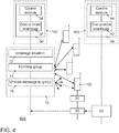
- Fig. 4 shows an embodiment of an apparatus 30 for a UE 100, an embodiment of an apparatus 40 for a base station 200, and an embodiment of a system 400.
- the apparatus 30 for the UE 100 comprises one or more interfaces 32 configured to communicate in the mobile communication system 400.
- the apparatus 30 further comprises a control module 34, which is coupled to the one or more interfaces 32 and which is configured to control the one or more interfaces 32.
- the control module 34 is further configured to perform one of the methods 10, 20 as described herein.
- the apparatus 40 for the base station 200 in a mobile communication system 400 comprises one or more interfaces 42, which are configured to communicate in the mobile communication system 400.
- the apparatus 40 further comprises a control module 44, which is coupled to the one or more interfaces 42 and which is configured to control the one or more interfaces 42.
- the control module 44 is further configured to perform one of the methods 50 as described herein.
- the apparatus 40 may be comprised in a base station 200, a NodeB, a relay station, or any service coordinating network entity in embodiments.
- a further embodiment is a vehicle comprising the apparatus 30 and/or the apparatus 40.
- the one or more interfaces 32, 42 may correspond to any means for obtaining, receiving, transmitting or providing analog or digital signals or information, e.g. any connector, contact, pin, register, input port, output port, conductor, lane, etc. which allows providing or obtaining a signal or information.
- An interface may be wireless or wireline and it may be configured to communicate, i.e. transmit or receive signals, information with further internal or external components.
- the one or more interfaces 32, 42 may comprise further components to enable according communication in the mobile communication system 400, such components may include transceiver (transmitter and/or receiver) components, such as one or more Low-Noise Amplifiers (LNAs), one or more Power-Amplifiers (PAs), one or more duplexers, one or more diplexers, one or more filters or filter circuitry, one or more converters, one or more mixers, accordingly adapted radio frequency components, etc.
- the one or more interfaces 32, 42 may be coupled to one or more antennas, which may correspond to any transmit and/or receive antennas, such as horn antennas, dipole antennas, patch antennas, sector antennas etc.
- the antennas may be arranged in a defined geometrical setting, such as a uniform array, a linear array, a circular array, a triangular array, a uniform field antenna, a field array, combinations thereof, etc.
- the one or more interfaces 32, 42 may serve the purpose of transmitting or receiving or both, transmitting and receiving, information, such as information related to capabilities, application requirements, trigger indications, requests, messages, data packets, acknowledgement packets/messages, etc.
- control modules 34, 44 may be implemented using one or more processing units, one or more processing devices, any means for processing, such as a processor, a computer or a programmable hardware component being operable with accordingly adapted software.
- the described functions of the control modules 34, 44 may as well be implemented in software, which is then executed on one or more programmable hardware components.
- Such hardware components may comprise a general purpose processor, a Digital Signal Processor (DSP), a microcontroller, etc.
- DSP Digital Signal Processor
- Fig. 4 also shows an embodiment of a system 400 comprising embodiments of UE 100, and a base station 200 comprising the apparatus 40.
- communication i.e. transmission, reception or both, may take place among mobile transceivers/vehicles 100 directly and/or between mobile transceivers/vehicles 100 and a network component (infrastructure or mobile transceiver, e.g. a base station, a network server, a backend server, etc.).
- a network component infrastructure or mobile transceiver, e.g. a base station, a network server, a backend server, etc.
- Such communication may make use of a mobile communication system 400.
- Such communication may be carried out directly, e.g. by means of device-to-device (D2D) communication, which may also comprise vehicle-to-vehicle (V2V) or car-to-car communication in case of vehicles 100.
- D2D device-to-device
- V2V
- Such communication may be carried out using the specifications of a mobile communication system 400.
- the one or more interfaces 32, 42 can be configured to wirelessly communicate in the mobile communication system 400.
- radio resources e.g. frequency, time, code, and/or spatial resources, which may be used for wireless communication with a base station transceiver as well as for direct communication.
- the assignment of the radio resources may be controlled by a base station transceiver, i.e. the determination which resources are used for D2D and which are not.
- radio resources of the respective components may correspond to any radio resources conceivable on radio carriers and they may use the same or different granularities on the respective carriers.
- the radio resources may correspond to a Resource Block (RB as in LTE/LTE-A/LTE-unlicensed (LTE-U)), one or more carriers, sub-carriers, one or more radio frames, radio sub-frames, radio slots, one or more code sequences potentially with a respective spreading factor, one or more spatial resources, such as spatial sub-channels, spatial precoding vectors, any combination thereof, etc.
- RB Resource Block
- transmission according to 3GPP Release 14 onward can be managed by infrastructure (so-called mode 3) or run in a UE.
- Fig. 4 also illustrates the methods 10 and 20, 50 as described above.
- the uplink scenario is explained first.
- the UE 100 wants to send a message to the base station 200 and determines 12 a coverage situation of the mobile communication system. It finds itself out of coverage of the base station 200 and forms 14 a group with other UEs. This group may as well have been established beforehand.
- the group is indicated by the four schematic UEs in the center of Fig. 4 liked with double sided arrows to the UE 100.
- the UE 100 then communicates 16 a unicast message to multiple UEs (indicated by the single-ended arrows) of the group of UEs based on the coverage situation of the mobile communication system 400.
- the UE 102 in this embodiment carries out the method 20, cf.
- UE 102 determines 24 whether the message is a unicast message, which was transmitted to multiple UEs and hence relays 26 the message to the base station 200.
- the method 50 is carried out at the base station 200.
- the base station 200 has a message or data packet to be transmitted to UE 100.
- the base station 200 determines 52 an out-of-coverage situation for the UE 100.
- the base station 200 determines 54 an identification of a group of multiple UEs the UE is assigned to. This group may have existed beforehand.
- the base station 200 hence transmits 56 the message to the group of UEs for relaying to the UE 100.
- UE 102 receives the message, carries out the method and relays the message to the UE 100, i.e. it relays in the opposite direction as compared to the above uplink scenario.
- the mobile communication system 400 may, for example, correspond to one of the Third Generation Partnership Project (3GPP)-standardized mobile communication networks, where the term mobile communication system is used synonymously to mobile communication network.
- the mobile or wireless communication system 400 may correspond to a mobile communication system of the 5th Generation (5G, or New Radio (NR)) and may use mm-Wave technology.
- 5G Fifth Generation
- NR New Radio
- the mobile communication system may correspond to or comprise, for example, a Long-Term Evolution (LTE), an LTE-Advanced (LTE-A), High Speed Packet Access (HSPA), a Universal Mobile Telecommunication System (UMTS) or a UMTS Terrestrial Radio Access Network (UTRAN), an evolved-UTRAN (e-UTRAN), a Global System for Mobile communication (GSM) or Enhanced Data rates for GSM Evolution (EDGE) network, a GSM/EDGE Radio Access Network (GERAN), or mobile communication networks with different standards, for example, a Worldwide Inter-operability for Microwave Access (WIMAX) network IEEE 802.16 or Wireless Local Area Network (WLAN) IEEE 802.11, generally an Orthogonal Frequency Division Multiple Access (OFDMA) network, a Time Division Multiple Access (TDMA) network, a Code Division Multiple Access (CDMA) network, a Wideband-CDMA (WCDMA) network, a Frequency Division Multiple Access (FDMA) network, a Spatial Division Multiple Access (SDMA) network, etc
- Service provision may be carried out by a network component, such as a base station transceiver 200, a relay station or a UE, e.g. coordinating service provision in a cluster or group of multiple UEs.
- a base station transceiver can be operable or configured to communicate with one or more active mobile transceivers/vehicles 100, 102 and a base station transceiver can be located in or adjacent to a coverage area of another base station transceiver, e.g. a macro cell base station transceiver or small cell base station transceiver.
- embodiments may provide a mobile communication system 400 comprising two or more mobile transceivers/vehicles 100, 102 and one or more base station transceivers, wherein the base station transceivers may establish macro cells or small cells, as e.g. pico-, metro-, or femto cells.
- a mobile transceiver or UE may correspond to a smartphone, a cell phone, a laptop, a notebook, a personal computer, a Personal Digital Assistant (PDA), a Universal Serial Bus (USB) -stick, a car, a vehicle etc.
- PDA Personal Digital Assistant
- USB Universal Serial Bus
- a mobile transceiver may also be referred to as User Equipment (UE) or mobile in line with the 3GPP terminology.
- UE User Equipment
- a vehicle may correspond to any conceivable means for transportation, e.g. a car, a bike, a motorbike, a van, a truck, a bus, a ship, a boat, a plane, a train, a tram, etc.
- a base station transceiver can be located in the fixed or stationary part of the network or system.
- a base station transceiver may be or correspond to a remote radio head, a transmission point, an access point, a macro cell, a small cell, a micro cell, a femto cell, a metro cell etc.
- a base station transceiver can be a wireless interface of a wired network, which enables transmission of radio signals to a UE or mobile transceiver.
- Such a radio signal may comply with radio signals as, for example, standardized by 3GPP or, generally, in line with one or more of the above listed systems.
- a base station transceiver may correspond to a NodeB, an eNodeB, a Base Transceiver Station (BTS), an access point, a remote radio head, a relay station, a transmission point etc., which may be further subdivided in a remote unit and a central unit.
- BTS Base Transceiver Station
- a mobile transceiver 100 can be associated with a base station transceiver or cell.
- the term cell refers to a coverage area of radio services provided by a base station transceiver, e.g. a NodeB (NB), an eNodeB (eNB), a remote radio head, a transmission point, etc.
- NB NodeB
- eNB eNodeB
- a base station transceiver may operate one or more cells on one or more frequency layers, in some embodiments a cell may correspond to a sector. For example, sectors can be achieved using sector antennas, which provide a characteristic for covering an angular section around a remote unit or base station transceiver.
- a base station transceiver may, for example, operate three or six cells covering sectors of 120° (in case of three cells), 60° (in case of six cells) respectively.
- a base station transceiver may operate multiple sectorized antennas.
- a cell may represent an according base station transceiver generating the cell or, likewise, a base station transceiver may represent a cell the base station transceiver generates.
- Mobile transceivers 100, 102 may communicate directly with each other, i.e. without involving any base station transceiver, which is also referred to as Device-to-Device (D2D) communication.
- D2D Device-to-Device
- An example of D2D is direct communication between vehicles, also referred to as Vehicle-to-Vehicle communication (V2V), car-to-car, DSRC, respectively.
- V2V Vehicle-to-Vehicle communication
- DSRC Vehicle-to-Vehicle communication
- technologies enabling such D2D-communication include 802.11p, 3GPP system (4G, 5G, NR and beyond), etc.
- Fig. 5 illustrates communication link configurations in embodiments, which are in line with 3GPP, cf. R2 1818728.
- Fig. 5 illustrates three communication scenarios in an embodiment using a 3GPP 5G or NR network/system.
- two vehicles/mobile transceivers 100, 102 communicate with a base station 200 over the Uu air interface.
- the two vehicles 100, 102 communicate directly with each other using D2D and the PC5 air interface.
- the two vehicles 100, 102 use both air interfaces Uu (towards base station 200) and PC5 (D2D) for communication.
- Fig. 6 illustrates an all-in-coverage scenario in an embodiment.
- Fig. 6 shows three base stations BS1-3 (200, 202, and 204).
- a group of vehicles V1-4 (100, 102, 104, and 106) are all located in the coverage of BS1 and the vehicles use PC5 communication to exchange information, for example location and speed data, route data, environmental data, sensor data, etc.
- Fig. 7 illustrates a scenario in which at least one vehicle has coverage in an embodiment.
- the scenario shows the same components as Fig. 6 .
- the group of vehicles V1-4 has moved on towards the right in Fig. 7 , where only vehicle V1, 100 is in coverage of BS1, 200.
- the other three vehicles V2-4 are in between the coverage areas of BS1 and BS2.
- vehicles V2-4 cannot directly communicate with any base station 200, 202, 204 because of lack of coverage.
- they can still communicate within the group via PC5.
- vehicle V4, 106 may communicate a message, which is addressing a recipient not shown in Fig. 7 , to vehicle 104.
- Vehicle 104 in turn could forward to vehicle 102 and vehicle 102 could forward it to vehicle 100.
- Vehicle 100 could forward it to the base station 200.
- the base station 200 could communicate a message to vehicle 106 through vehicles 100, 102, 104 (multi-hop chain in the opposite direction).
- the unicast message (message from V4 to base station 200 or vice versa) is directed to multiple UEs of the group of UEs wrapped up, tunneled or being comprised in a multicast or broadcast message.
- a network component e.g. UE or base station
- the respective message or data packet can be packed into a broadcast or multicast message or packet, which is then sent out to the group.
- Such group communication may be organized by using certain identification.
- the forming 14 of the group of UEs may comprise assigning a group or groupcast identification to the group of UEs. Members of the group would then know and react to messages which are addressed with such an identification.
- the method may further comprise using the group identification or a groupcast identification to address the unicast message to the group of UEs.
- the forming 14 of the group of UEs may comprise determining group members based on a common geographic path or location of the UEs.
- the group of UEs may drive a certain highway section together (common path).
- the UEs/vehicles may communicate their routes or destinations and hence find each other as road companions at least for a certain route section.
- a message may comprise payload (e.g. the unicast message) and control information (e.g. header or tail information).
- the control information may have information relating to the forwarding and relaying of the message.
- the control information may comprise an identifier so a UE could determine whether a message was received/relayed before.
- a UE may only repeat/relay a message for a predetermined number of times, e.g. once or twice.
- a message may comprise a counter indicating how many times it has been relayed before. For example, the counter is increased any time the message gets relayed.
- the determining 12 of the coverage situation may comprise looking up coverage information in a coverage map based on a location of the UE/vehicle 106.
- the vehicle 106 may use a coverage map relating geographical locations to information on whether network coverage is available or not.
- a coverage map or coverage information may be stored in a memory or storage of the vehicle. For example, such information may be made available for download by an operator of the mobile communication system 400.
- the determining 12 of the coverage situation may comprise measuring a signal from the mobile communication system 400.
- the signal is indicative of the coverage of the mobile communication system 400. Multiple such signals are known or conceivable, examples are reference signals/symbols, pilot signals/symbols, synchronization signals/symbols, etc.
- multiple measurements are conceivable, which may lead to said coverage information.
- Such measurements may be based on a signal-to-noise ratio (SNR), signal-to-interference ratio (SIR), signal-to-noise-and-interference ratio (SINR), receive power strength, receive signal code power (RSCP), receive signal strength indicator (RSSI), pathloss, latency, etc.
- SNR signal-to-noise ratio
- SIR signal-to-interference ratio
- SINR signal-to-noise-and-interference ratio
- receive power strength receive signal code power
- RSSI receive signal strength indicator
- the method 10 further comprises receiving the message, which is addressing the multiple UEs, from UE 106 or the base station 200, and determining whether the message is a unicast message, which was transmitted to multiple UEs.
- the method then further comprises relaying the message if it is a unicast message, which was transmitted to multiple UEs.
- the relaying comprises relaying the unicast message to another UE, to a base station of the mobile communication system, or to the group of UEs.
- the method 10 describes the behavior of UE 106 in this embodiment, which sends the unicast message to the group of UEs 100, 102, 104 (uplink).
- the method 20 comprises receiving 22 the message, which is addressing multiple UEs, from another UE (the first UE), determining 24 whether the message is a unicast message, which was transmitted to multiple UEs, and relaying 26 the message if it is a unicast message, which was transmitted to multiple UEs.
- the relaying or forwarding may be to other UEs of the group, to other UEs of another group or to a base station. As lined out above, the relaying may be limited by a counter (limited umber of hops).
- the above method 50 may be carried out.
- the method 50 comprises determining 52 an out-of-coverage situation for user equipment, UE, to which a message is to be sent.
- the method 50 further comprises determining 54 an identification of a group of multiple UEs the UE is assigned to.
- the method 50 further comprises transmitting 56 the message to the group of UEs for relaying to the UE.
- This method 50 may apply when the base station knows a group the target UE is assigned to but has no direct link to the UE.
- the base station 200 may page the UE 106 but does not receive a paging response.
- the base station Since the base station knows that another UE 100 of the group is still under coverage, it broad- or multicasts the message for UE 106 to the group. For example, information may be maintained at the base station 200 or another network component on which groups are in coverage of the base station 200. Moreover, information on which UEs a assigned to which groups may also be available, such that a base station 200 may decide based on the available information, whether to use the above mechanism.
- the base station 200 and/or the UE 106 may transmit an acknowledgement packet after reception of the message or data packet.
- the same mechanisms may apply to the forwarding/relaying of the acknowledgement data packet as lined out above for the message/data packet.
- the method 50 at the base station 200 may further comprise receiving the acknowledgment message (uplink) from another 100 UE after transmitting the message (downlink).
- the method 50 at the base station 200 may further comprise receiving the acknowledgment message (uplink) from another UE 100 after transmitting the message (downlink).
- Fig. 8 illustrates a scenario in which two vehicles of a group of vehicles have coverage of different base stations 200, 202.
- Fig. 8 shows a similar scenario as the previous Figs.
- UE 100 is in coverage of base station 200
- UE 106 is in coverage of base station 106.
- UEs 102, 104 would hence have two chances of reaching the network, one through the group chain ending up at base station 200 (via UE 100) and another one through the group ending up at base station 202 (via UE 106).
- Fig. 9 illustrates an out-of-coverage scenario, in which the group of UEs 100, 102, 104, 106 is located between the coverage areas of base stations 202 and 204.
- Messages sent out within the group cannot be transmitted outside the group. However they may be buffered and forwarded to a base station when back in coverage. Likewise, a base station cannot transmit any messages to the group and may store such a message until at least one UE of the group can be reached. If the group enters coverage of another base station the base stations may communicated among each other such that the message can be delivered to the group and eventually to the desired recipient.
- vehicles may use a communication map (vehicles know where coverage is and where not). Vehicles which are expected to drive close by for certain time through an area with poor coverage may build or form a communication group (CG).
- a CG may establish a mesh network.
- the CG gets a groupcast identification assigned.
- a request may be sent from one UE towards a BS but in the downlink the group cast address may be used in order to increase the reception probability. If a requested vehicle was not able to get a response from the BS it may obtain the data via sidelink (e.g. PC5) from the other UE's.
- sidelink e.g. PC5
- the respective methods may be implemented as computer programs or codes, which can be executed on a respective hardware.
- another embodiment is a computer program having a program code for performing at least one of the above methods, when the computer program is executed on a computer, a processor, or a programmable hardware component.
- a further embodiment is a (non-transitory) computer readable storage medium storing instructions which, when executed by a computer, processor, or programmable hardware component, cause the computer to implement one of the methods described herein.
- program storage devices e.g., digital data storage media, which are machine or computer readable and encode machine-executable or computer-executable programs of instructions where said instructions perform some or all of the steps of methods described herein.
- the program storage devices may be, e.g., digital memories, magnetic storage media such as magnetic disks and magnetic tapes, hard drives, or optically readable digital data storage media.
- the embodiments are also intended to cover computers programmed to perform said steps of methods described herein or (field) programmable logic arrays ((F)PLAs) or (field) programmable gate arrays ((F)PGAs), programmed to perform said steps of the above-described methods.
- processor When provided by a processor, the functions may be provided by a single dedicated processor, by a single shared processor, or by a plurality of individual processors, some of which may be shared.
- explicit use of the term "processor” or “controller” should not be construed to refer exclusively to hardware capable of executing software, and may implicitly include, without limitation, Digital Signal Processor (DSP) hardware, network processor, application specific integrated circuit (ASIC), field programmable gate array (FPGA), read only memory (ROM) for storing software, random access memory (RAM), and non-volatile storage. Other hardware, conventional or custom, may also be included. Their function may be carried out through the operation of program logic, through dedicated logic, through the interaction of program control and dedicated logic, or even manually, the particular technique being selectable by the implementer as more specifically understood from the context.
- DSP Digital Signal Processor
- ASIC application specific integrated circuit
- FPGA field programmable gate array
- ROM read only memory
- RAM random access memory
- non-volatile storage Other hardware
- any block diagrams herein represent conceptual views of illustrative circuitry embodying the principles of the invention.
- any flow charts, flow diagrams, state transition diagrams, pseudo code, and the like represent various processes which may be substantially represented in computer readable medium and so executed by a computer or processor, whether or not such computer or processor is explicitly shown.
- each claim may stand on its own as a separate embodiment. While each claim may stand on its own as a separate embodiment, it is to be noted that - although a dependent claim may refer in the claims to a specific combination with one or more other claims - other embodiments may also include a combination of the dependent claim with the subject matter of each other dependent claim. Such combinations are proposed herein unless it is stated that a specific combination is not intended. Furthermore, it is intended to include also features of a claim to any other independent claim even if this claim is not directly made dependent to the independent claim.
Abstract
Description
- The present invention relates to a system, a vehicle, apparatuses, methods, and computer programs for user equipment, UE, and a base station in a mobile communication system, more particularly, but not exclusively, to a concept for transmitting a unicast message to a group of UEs for further relaying in an out-of-coverage situation.
- Document
US 2018/0077518 A1 describes a concept for sharing sensor data among vehicles. Common information is broadcast to nearby vehicles. Based on the common information some vehicles may request more detailed information. Unicast and/or multicast sessions may be set up to share the detailed information. DocumentWO 2017/075920 A1 discloses a data transmission method and device for vehicle communications, base station, and network side device. The data transmission method determines, according to a number of receiving terminals receiving the vehicle communication data or according to instruction information sent by the sending terminal, whether to use a unicast mode or a broadcast mode to transmit the vehicle communication data. If a broadcast mode is determined to be used to transmit the vehicle communication data, then a range where the vehicle communication data needs to be broadcast is determined. According to the range where the vehicle communication data needs to be broadcast, a single-cell broadcast mode or a multi-cell broadcast mode to transmit the vehicle communication data is selected. R2-1818728 is a 3GPP (3rd Generation Partnership Project) meeting contribution relating to unicast, groupcast, and broadcast support for in-coverage, out-of-coverage, and partial coverage scenarios. - Conventional concepts evaluate different communication possibilities for inter vehicular communication in different coverage scenarios. Communication with communication partners, which are out-of-coverage, is not considered.
- There is a demand for an improved concept for communicating in different coverage scenarios of a mobile communication system.
- Embodiments are based on the finding that UEs can be organized in groups for group communication and that the UEs within such a group may experience different coverage scenarios. It is a further finding that a UE being out-of-coverage, OOC, of a base station may still communicate with such a base station through one or more other UEs, which are in the same group and in coverage of the base station. The OOC-UE may broadcast or multicast a message, which is actually a unicast message, to the group of UEs, and group members may then forward the message.
- Embodiments provide a method for user equipment, UE, in a mobile communication system. The method comprises determining a coverage situation of the mobile communication system, forming a group of multiple UEs, and communicating a unicast message to multiple UEs of the group of UEs based on the coverage situation of the mobile communication system. A reliability or robustness of wireless communication may be increased by communicating a unicast message to multiple UEs. Embodiments may enable an enhanced uplink communication in a mobile communication system.
- The communicating of the unicast message directed to the multiple UEs of the group of UEs may be carried out if the UE is out of coverage of a base station of the mobile communication system in some embodiments. Coverage of a base station may be enhanced by using group communication.
- For example, the unicast message directed to multiple UEs of the group of UEs may be comprised in or wrapped into a multicast or broadcast message. The forming of the group of UEs may comprise assigning a group or groupcast identification to the group of UEs. In some embodiments the method may further comprise using the group identification or a groupcast identification to address the unicast message to the group of UEs. Embodiments may enable a simple and efficient mechanism to enhance coverage in a mobile communication system using direct communication between UEs.
- In some embodiments the forming of the group of UEs may comprise determining group members based on a common geographic path or location of the UEs. Embodiments may form groups or clusters of co-allocated UEs or UEs sharing the same route. Such grouping or clustering may further contribute to enhance communication efficiency.
- The determining of the coverage situation may comprise looking up coverage information in a coverage map based on a location of the UE. Coverage maps may contribute to a simple and efficient way of distinguishing areas with different coverage qualities/situations. Additionally or alternatively, the determining of the coverage situation may comprise measuring a signal from the mobile communication system, wherein the signal is indicative of the coverage of the mobile communication system. Coverage measurements may help determining an up-to-date coverage situation at certain location, even when the network infrastructure changes (for example added base stations/cells).
- The method may, in some further embodiments, comprise receiving a message, which is addressing multiple UEs, from another UE. The method may further comprise determining whether the message is a unicast message, which was transmitted to multiple UEs, and relaying the message if it is a unicast message, which was transmitted to multiple UEs. UEs may be configured to relay such messages in order to eventually transmit the message to its dedicated receiver. The relaying may comprise relaying the unicast message to another UE, to a base station of the mobile communication system, or to the group of UEs. UEs may establish an adaptive and dynamic adhoc network component.
- Embodiments further provide a method for user equipment, UE, in a mobile communication system. The method comprises receiving a message, which is addressing multiple UEs, from another UE, determining whether the message is a unicast message, which was transmitted to multiple UEs, and relaying the message if it is a unicast message, which was transmitted to multiple UEs. UEs may therewith be enabled to form a multi-hop or adhoc network component, even if they are not capable of transmitting a unicast message to multiple UEs. The relaying may comprise relaying the unicast message to another UE, to a base station of the mobile communication system, or to the group of UEs.
- An apparatus for user equipment, UE, in a mobile communication system is another embodiment. The apparatus comprises one or more interfaces, which are configured to communicate in the mobile communication system. The apparatus further comprises a control module, which is configured to control the one or more interfaces. The control module is further configured to perform one of the methods described herein.
- Another embodiment is a method for a base station in a mobile communication system. The method comprises determining an out-of-coverage situation for user equipment, UE, to which a message is to be sent. The method further comprises determining an identification of a group of multiple UEs the UE is assigned to. The method further comprises transmitting the message to the group of UEs for relaying to the UE. Embodiments may also enable to use an adhoc or multi-hop network component in the downlink.
- The method may further comprise receiving an acknowledgment message for the message from a UE of the group. Embodiments may use the adhoc or multi-hop component for receiving acknowledgements for transmitted messages or data packets.
- Embodiments also provide an apparatus for a base station in a mobile communication system. The apparatus comprises one or more interfaces, which are configured to communicate in the mobile communication system. The apparatus further comprises a control module, which is configured to control the one or more interfaces. The control module is further configured to perform one of the methods described herein. A further embodiment is a vehicle comprising one of the apparatuses described herein.
- Embodiments further provide a computer program having a program code for performing one or more of the above described methods, when the computer program is executed on a computer, processor, or programmable hardware component. A further embodiment is a computer readable storage medium storing instructions which, when executed by a computer, processor, or programmable hardware component, cause the computer to implement one of the methods described herein.
- Some other features or aspects will be described using the following non-limiting embodiments of apparatuses or methods or computer programs or computer program products by way of example only, and with reference to the accompanying figures, in which:
-
Fig. 1 illustrates a block diagram of an embodiment of a method for user equipment; -
Fig. 2 illustrates a block diagram of an embodiment of another method for user equipment; -
Fig. 3 illustrates a block diagram of an embodiment of a method for a base station; -
Fig. 4 shows an embodiment of an apparatus for a UE, an embodiment of an apparatus for a base station, and an embodiment of a system; -
Fig. 5 illustrates communication link configurations in embodiments; -
Fig. 6 illustrates an all-in-coverage scenario in an embodiment; -
Fig. 7 illustrates a scenario in which at least one vehicle has coverage in an embodiment; -
Fig. 8 illustrates a scenario in which two vehicles of a group of vehicles have coverage of different base stations; and -
Fig. 9 illustrates an out-of-coverage scenario. - Various example embodiments will now be described more fully with reference to the accompanying drawings in which some example embodiments are illustrated. In the figures, the thicknesses of lines, layers or regions may be exaggerated for clarity. Optional components may be illustrated using broken, dashed or dotted lines.
- Accordingly, while example embodiments are capable of various modifications and alternative forms, embodiments thereof are shown by way of example in the figures and will herein be described in detail. It should be understood, however, that there is no intent to limit example embodiments to the particular forms disclosed, but on the contrary, example embodiments are to cover all modifications, equivalents, and alternatives falling within the scope of the invention. Like numbers refer to like or similar elements throughout the description of the figures.
- As used herein, the term "or" refers to a non-exclusive or, unless otherwise indicated (e.g., "or else" or "or in the alternative"). Furthermore, as used herein, words used to describe a relationship between elements should be broadly construed to include a direct relationship or the presence of intervening elements unless otherwise indicated. For example, when an element is referred to as being "connected" or "coupled" to another element, the element may be directly connected or coupled to the other element or intervening elements may be present. In contrast, when an element is referred to as being "directly connected" or "directly coupled" to another element, there are no intervening elements present. Similarly, words such as "between", "adjacent", and the like should be interpreted in a like fashion.
- The terminology used herein is for the purpose of describing particular embodiments only and is not intended to be limiting of example embodiments. As used herein, the singular forms "a", "an" and "the" are intended to include the plural forms as well, unless the context clearly indicates otherwise. It will be further understood that the terms "comprises", "comprising", "includes" or "including", when used herein, specify the presence of stated features, integers, steps, operations, elements or components, but do not preclude the presence or addition of one or more other features, integers, steps, operations, elements, components or groups thereof. Unless otherwise defined, all terms (including technical and scientific terms) used herein have the same meaning as commonly understood by one of ordinary skill in the art to which example embodiments belong. It will be further understood that terms, e.g., those defined in commonly used dictionaries, should be interpreted as having a meaning that is consistent with their meaning in the context of the relevant art and will not be interpreted in an idealized or overly formal sense unless expressly so defined herein.
-
Fig. 1 illustrates a block diagram of an embodiment of amethod 10 for user equipment, UE, in a mobile communication system. Themethod 10 comprises determining 12 a coverage situation of the mobile communication system, forming 14 a group of multiple UEs, and communicating 16 a unicast message to multiple UEs of the group of UEs based on the coverage situation of the mobile communication system. For example, the communicating 16 of the unicast message directed to multiple UEs of the group of UEs is carried out if the UE is out of coverage of a base station of the mobile communication system. - The
method 10 describes the behavior from the perspective of a first UE, which, for example, tries to send a message to a second UE, which is located far away. Since the second UE cannot be reached directly and further assuming that there is no coverage of a base station, the first UE sends the unicast message to a group of UEs. Herein a unicast message is a message, which is sent point-to-point (ptp), i.e. from one sender to one addressee. A multicast message is a message, which is sent point-to-multipoint (ptm), i.e. from one sender to multiple addressees, e.g. a group of UEs or service subscribers etc. A broadcast message is a message, which is sent point-to-multipoint (ptm), i.e. from one sender to any addressee, e.g. any receiver located in the coverage of the sender. -
Fig. 2 illustrates a block diagram of an embodiment of amethod 20 for user equipment, UE of the group, in a mobile communication system.Method 20 describes the behavior of a UE in the group of UEs. Themethod 20 comprises receiving 22 the message, which is addressing multiple UEs, from another UE (the first UE). The method further comprises determining 24 whether the message is a unicast message, which was transmitted to multiple UEs, and relaying 26 the message if it is a unicast message, which was transmitted to multiple UEs. In an embodiment the second UE relay the message to other UEs of the group, to other UEs of another group or to a base station. The relaying 26 may comprise relaying the unicast message to another UE, to a base station of the mobile communication system, or to the group of UEs. - This way, embodiments may establish a communication chain (multi-hop/adhoc network), which can eventually lead to the above second UE, which could be directly or via the network infrastructure (base station). In the other direction, downlink, the same consideration may apply. The procedure then starts at a base station.
-
Fig. 3 illustrates a block diagram of an embodiment of amethod 50 for a base station in a mobile communication system. Themethod 50 comprises determining 52 an out-of-coverage situation for user equipment, UE, to which a message is to be sent. Themethod 50 further comprises determining 54 an identification of a group of multiple UEs the UE is assigned to. Themethod 50 further comprises transmitting 56 the message to the group of UEs for relaying to the UE. Thismethod 50 may apply if the base station knows a group the target UE is assigned to but has no direct link to the UE. The coverage may then be extended by using other group members to eventually reach the desired UE through relaying as described above. The method may further comprise receiving an acknowledgment message for the message from a UE of the group. -
Fig. 4 shows an embodiment of anapparatus 30 for aUE 100, an embodiment of anapparatus 40 for abase station 200, and an embodiment of asystem 400. Theapparatus 30 for theUE 100 comprises one ormore interfaces 32 configured to communicate in themobile communication system 400. Theapparatus 30 further comprises acontrol module 34, which is coupled to the one ormore interfaces 32 and which is configured to control the one ormore interfaces 32. Thecontrol module 34 is further configured to perform one of themethods - The
apparatus 40 for thebase station 200 in amobile communication system 400 comprises one ormore interfaces 42, which are configured to communicate in themobile communication system 400. Theapparatus 40 further comprises acontrol module 44, which is coupled to the one ormore interfaces 42 and which is configured to control the one ormore interfaces 42. Thecontrol module 44 is further configured to perform one of themethods 50 as described herein. Theapparatus 40 may be comprised in abase station 200, a NodeB, a relay station, or any service coordinating network entity in embodiments. A further embodiment is a vehicle comprising theapparatus 30 and/or theapparatus 40. - In embodiments the one or
more interfaces more interfaces mobile communication system 400, such components may include transceiver (transmitter and/or receiver) components, such as one or more Low-Noise Amplifiers (LNAs), one or more Power-Amplifiers (PAs), one or more duplexers, one or more diplexers, one or more filters or filter circuitry, one or more converters, one or more mixers, accordingly adapted radio frequency components, etc. The one ormore interfaces more interfaces - As shown in
Fig. 4 the respective one ormore interfaces respective control modules apparatuses control modules control modules -
Fig. 4 also shows an embodiment of asystem 400 comprising embodiments ofUE 100, and abase station 200 comprising theapparatus 40. In embodiments, communication, i.e. transmission, reception or both, may take place among mobile transceivers/vehicles 100 directly and/or between mobile transceivers/vehicles 100 and a network component (infrastructure or mobile transceiver, e.g. a base station, a network server, a backend server, etc.). Such communication may make use of amobile communication system 400. Such communication may be carried out directly, e.g. by means of device-to-device (D2D) communication, which may also comprise vehicle-to-vehicle (V2V) or car-to-car communication in case ofvehicles 100. - Such communication may be carried out using the specifications of a
mobile communication system 400. - In embodiments the one or
more interfaces mobile communication system 400. In order to do so radio resources are used, e.g. frequency, time, code, and/or spatial resources, which may be used for wireless communication with a base station transceiver as well as for direct communication. The assignment of the radio resources may be controlled by a base station transceiver, i.e. the determination which resources are used for D2D and which are not. Here and in the following radio resources of the respective components may correspond to any radio resources conceivable on radio carriers and they may use the same or different granularities on the respective carriers. The radio resources may correspond to a Resource Block (RB as in LTE/LTE-A/LTE-unlicensed (LTE-U)), one or more carriers, sub-carriers, one or more radio frames, radio sub-frames, radio slots, one or more code sequences potentially with a respective spreading factor, one or more spatial resources, such as spatial sub-channels, spatial precoding vectors, any combination thereof, etc. - For example, in direct cellular vehicle-to-anything (C-V2X), where V2X includes at least V2V, V2-Infrastructure (V2I), etc., transmission according to
3GPP Release 14 onward can be managed by infrastructure (so-called mode 3) or run in a UE. -
Fig. 4 also illustrates themethods UE 100 wants to send a message to thebase station 200 and determines 12 a coverage situation of the mobile communication system. It finds itself out of coverage of thebase station 200 and forms 14 a group with other UEs. This group may as well have been established beforehand. The group is indicated by the four schematic UEs in the center ofFig. 4 liked with double sided arrows to theUE 100. TheUE 100 then communicates 16 a unicast message to multiple UEs (indicated by the single-ended arrows) of the group of UEs based on the coverage situation of themobile communication system 400. TheUE 102 in this embodiment carries out themethod 20, cf.Fig. 2 . Accordingly, it receives the message fromUE 100, which is addressing the multiple UEs.UE 102 determines 24 whether the message is a unicast message, which was transmitted to multiple UEs and hence relays 26 the message to thebase station 200. - For the downlink direction the
method 50 is carried out at thebase station 200. Thebase station 200 has a message or data packet to be transmitted toUE 100. Thebase station 200 determines 52 an out-of-coverage situation for theUE 100. Thebase station 200 determines 54 an identification of a group of multiple UEs the UE is assigned to. This group may have existed beforehand. Thebase station 200 hence transmits 56 the message to the group of UEs for relaying to theUE 100.UE 102 receives the message, carries out the method and relays the message to theUE 100, i.e. it relays in the opposite direction as compared to the above uplink scenario. - The
mobile communication system 400, as shown inFig. 4 , may, for example, correspond to one of the Third Generation Partnership Project (3GPP)-standardized mobile communication networks, where the term mobile communication system is used synonymously to mobile communication network. The mobile orwireless communication system 400 may correspond to a mobile communication system of the 5th Generation (5G, or New Radio (NR)) and may use mm-Wave technology. The mobile communication system may correspond to or comprise, for example, a Long-Term Evolution (LTE), an LTE-Advanced (LTE-A), High Speed Packet Access (HSPA), a Universal Mobile Telecommunication System (UMTS) or a UMTS Terrestrial Radio Access Network (UTRAN), an evolved-UTRAN (e-UTRAN), a Global System for Mobile communication (GSM) or Enhanced Data rates for GSM Evolution (EDGE) network, a GSM/EDGE Radio Access Network (GERAN), or mobile communication networks with different standards, for example, a Worldwide Inter-operability for Microwave Access (WIMAX) network IEEE 802.16 or Wireless Local Area Network (WLAN) IEEE 802.11, generally an Orthogonal Frequency Division Multiple Access (OFDMA) network, a Time Division Multiple Access (TDMA) network, a Code Division Multiple Access (CDMA) network, a Wideband-CDMA (WCDMA) network, a Frequency Division Multiple Access (FDMA) network, a Spatial Division Multiple Access (SDMA) network, etc. - Service provision may be carried out by a network component, such as a
base station transceiver 200, a relay station or a UE, e.g. coordinating service provision in a cluster or group of multiple UEs. A base station transceiver can be operable or configured to communicate with one or more active mobile transceivers/vehicles mobile communication system 400 comprising two or more mobile transceivers/vehicles - A base station transceiver can be located in the fixed or stationary part of the network or system. A base station transceiver may be or correspond to a remote radio head, a transmission point, an access point, a macro cell, a small cell, a micro cell, a femto cell, a metro cell etc. A base station transceiver can be a wireless interface of a wired network, which enables transmission of radio signals to a UE or mobile transceiver. Such a radio signal may comply with radio signals as, for example, standardized by 3GPP or, generally, in line with one or more of the above listed systems. Thus, a base station transceiver may correspond to a NodeB, an eNodeB, a Base Transceiver Station (BTS), an access point, a remote radio head, a relay station, a transmission point etc., which may be further subdivided in a remote unit and a central unit.
- A
mobile transceiver 100 can be associated with a base station transceiver or cell. The term cell refers to a coverage area of radio services provided by a base station transceiver, e.g. a NodeB (NB), an eNodeB (eNB), a remote radio head, a transmission point, etc. A base station transceiver may operate one or more cells on one or more frequency layers, in some embodiments a cell may correspond to a sector. For example, sectors can be achieved using sector antennas, which provide a characteristic for covering an angular section around a remote unit or base station transceiver. In some embodiments, a base station transceiver may, for example, operate three or six cells covering sectors of 120° (in case of three cells), 60° (in case of six cells) respectively. A base station transceiver may operate multiple sectorized antennas. In the following a cell may represent an according base station transceiver generating the cell or, likewise, a base station transceiver may represent a cell the base station transceiver generates. -
Mobile transceivers -
Fig. 5 illustrates communication link configurations in embodiments, which are in line with 3GPP, cf. R2 1818728.Fig. 5 illustrates three communication scenarios in an embodiment using a 3GPP 5G or NR network/system. On the left-hand side two vehicles/mobile transceivers base station 200 over the Uu air interface. In the center the twovehicles vehicles -
Fig. 6 illustrates an all-in-coverage scenario in an embodiment.Fig. 6 shows three base stations BS1-3 (200, 202, and 204). A group of vehicles V1-4 (100, 102, 104, and 106) are all located in the coverage of BS1 and the vehicles use PC5 communication to exchange information, for example location and speed data, route data, environmental data, sensor data, etc. -
Fig. 7 illustrates a scenario in which at least one vehicle has coverage in an embodiment. The scenario shows the same components asFig. 6 . The group of vehicles V1-4 has moved on towards the right inFig. 7 , where only vehicle V1, 100 is in coverage of BS1, 200. The other three vehicles V2-4 are in between the coverage areas of BS1 and BS2. Hence, in such a scenario vehicles V2-4 cannot directly communicate with anybase station Fig. 7 , tovehicle 104.Vehicle 104 in turn could forward tovehicle 102 andvehicle 102 could forward it tovehicle 100.Vehicle 100 could forward it to thebase station 200. Likewise, thebase station 200 could communicate a message tovehicle 106 throughvehicles - In some embodiments the unicast message (message from V4 to
base station 200 or vice versa) is directed to multiple UEs of the group of UEs wrapped up, tunneled or being comprised in a multicast or broadcast message. E.g. once a network component (e.g. UE or base station) notices that a recipient cannot directly be reached, the respective message or data packet can be packed into a broadcast or multicast message or packet, which is then sent out to the group. Such group communication may be organized by using certain identification. The forming 14 of the group of UEs may comprise assigning a group or groupcast identification to the group of UEs. Members of the group would then know and react to messages which are addressed with such an identification. The method may further comprise using the group identification or a groupcast identification to address the unicast message to the group of UEs. For example, the forming 14 of the group of UEs may comprise determining group members based on a common geographic path or location of the UEs. In the embodiment shown inFigs. 6-9 the group of UEs may drive a certain highway section together (common path). The UEs/vehicles may communicate their routes or destinations and hence find each other as road companions at least for a certain route section. - In embodiments certain protocol provisions may apply with respect to the forming of groups or clusters and with respect to relaying or repeating the message. For example, a message may comprise payload (e.g. the unicast message) and control information (e.g. header or tail information). The control information may have information relating to the forwarding and relaying of the message. For example, the control information may comprise an identifier so a UE could determine whether a message was received/relayed before. A UE may only repeat/relay a message for a predetermined number of times, e.g. once or twice. Moreover, a message may comprise a counter indicating how many times it has been relayed before. For example, the counter is increased any time the message gets relayed. These mechanisms may avoid loops and may limit the overhead introduced by the relaying mechanism.
- The determining 12 of the coverage situation may comprise looking up coverage information in a coverage map based on a location of the UE/
vehicle 106. Thevehicle 106 may use a coverage map relating geographical locations to information on whether network coverage is available or not. Such a coverage map or coverage information may be stored in a memory or storage of the vehicle. For example, such information may be made available for download by an operator of themobile communication system 400. In other embodiments the determining 12 of the coverage situation may comprise measuring a signal from themobile communication system 400. The signal is indicative of the coverage of themobile communication system 400. Multiple such signals are known or conceivable, examples are reference signals/symbols, pilot signals/symbols, synchronization signals/symbols, etc. In embodiments multiple measurements are conceivable, which may lead to said coverage information. Such measurements may be based on a signal-to-noise ratio (SNR), signal-to-interference ratio (SIR), signal-to-noise-and-interference ratio (SINR), receive power strength, receive signal code power (RSCP), receive signal strength indicator (RSSI), pathloss, latency, etc. - From the perspective of
UEs method 10 further comprises receiving the message, which is addressing the multiple UEs, fromUE 106 or thebase station 200, and determining whether the message is a unicast message, which was transmitted to multiple UEs. The method then further comprises relaying the message if it is a unicast message, which was transmitted to multiple UEs. The relaying comprises relaying the unicast message to another UE, to a base station of the mobile communication system, or to the group of UEs. Themethod 10 describes the behavior ofUE 106 in this embodiment, which sends the unicast message to the group ofUEs UEs above method 20, which describes the behavior as part of the group (relaying but not necessarily initiating the transmission of the unicast message to the group). Themethod 20 comprises receiving 22 the message, which is addressing multiple UEs, from another UE (the first UE), determining 24 whether the message is a unicast message, which was transmitted to multiple UEs, and relaying 26 the message if it is a unicast message, which was transmitted to multiple UEs. The relaying or forwarding may be to other UEs of the group, to other UEs of another group or to a base station. As lined out above, the relaying may be limited by a counter (limited umber of hops). - In the opposite direction from the
base station 200 to the UE 106 (downlink) theabove method 50 may be carried out. Themethod 50 comprises determining 52 an out-of-coverage situation for user equipment, UE, to which a message is to be sent. Themethod 50 further comprises determining 54 an identification of a group of multiple UEs the UE is assigned to. Themethod 50 further comprises transmitting 56 the message to the group of UEs for relaying to the UE. Thismethod 50 may apply when the base station knows a group the target UE is assigned to but has no direct link to the UE. In some embodiments thebase station 200 may page theUE 106 but does not receive a paging response. Since the base station knows that anotherUE 100 of the group is still under coverage, it broad- or multicasts the message forUE 106 to the group. For example, information may be maintained at thebase station 200 or another network component on which groups are in coverage of thebase station 200. Moreover, information on which UEs a assigned to which groups may also be available, such that abase station 200 may decide based on the available information, whether to use the above mechanism. - Depending on the communication protocols involved, the
base station 200 and/or theUE 106 may transmit an acknowledgement packet after reception of the message or data packet. The same mechanisms may apply to the forwarding/relaying of the acknowledgement data packet as lined out above for the message/data packet. Themethod 50 at thebase station 200 may further comprise receiving the acknowledgment message (uplink) from another 100 UE after transmitting the message (downlink). Themethod 50 at thebase station 200 may further comprise receiving the acknowledgment message (uplink) from anotherUE 100 after transmitting the message (downlink). -
Fig. 8 illustrates a scenario in which two vehicles of a group of vehicles have coverage ofdifferent base stations Fig. 8 shows a similar scenario as the previous Figs. In the scenario depictedUE 100 is in coverage ofbase station 200 andUE 106 is in coverage ofbase station 106.UEs Fig. 9 illustrates an out-of-coverage scenario, in which the group ofUEs base stations - In embodiment vehicles may use a communication map (vehicles know where coverage is and where not). Vehicles which are expected to drive close by for certain time through an area with poor coverage may build or form a communication group (CG). A CG may establish a mesh network. In some embodiments the CG gets a groupcast identification assigned. A request may be sent from one UE towards a BS but in the downlink the group cast address may be used in order to increase the reception probability. If a requested vehicle was not able to get a response from the BS it may obtain the data via sidelink (e.g. PC5) from the other UE's.
- As already mentioned, in embodiments the respective methods may be implemented as computer programs or codes, which can be executed on a respective hardware. Hence, another embodiment is a computer program having a program code for performing at least one of the above methods, when the computer program is executed on a computer, a processor, or a programmable hardware component. A further embodiment is a (non-transitory) computer readable storage medium storing instructions which, when executed by a computer, processor, or programmable hardware component, cause the computer to implement one of the methods described herein.
- A person of skill in the art would readily recognize that steps of various above-described methods can be performed by programmed computers, for example, positions of slots may be determined or calculated. Herein, some embodiments are also intended to cover program storage devices, e.g., digital data storage media, which are machine or computer readable and encode machine-executable or computer-executable programs of instructions where said instructions perform some or all of the steps of methods described herein. The program storage devices may be, e.g., digital memories, magnetic storage media such as magnetic disks and magnetic tapes, hard drives, or optically readable digital data storage media. The embodiments are also intended to cover computers programmed to perform said steps of methods described herein or (field) programmable logic arrays ((F)PLAs) or (field) programmable gate arrays ((F)PGAs), programmed to perform said steps of the above-described methods.
- The description and drawings merely illustrate the principles of the invention. It will thus be appreciated that those skilled in the art will be able to devise various arrangements that, although not explicitly described or shown herein, embody the principles of the invention and are included within its spirit and scope. Furthermore, all examples recited herein are principally intended expressly to be only for pedagogical purposes to aid the reader in understanding the principles of the invention and the concepts contributed by the inventor(s) to furthering the art, and are to be construed as being without limitation to such specifically recited examples and conditions. Moreover, all statements herein reciting principles, aspects, and embodiments of the invention, as well as specific examples thereof, are intended to encompass equivalents thereof. When provided by a processor, the functions may be provided by a single dedicated processor, by a single shared processor, or by a plurality of individual processors, some of which may be shared. Moreover, explicit use of the term "processor" or "controller" should not be construed to refer exclusively to hardware capable of executing software, and may implicitly include, without limitation, Digital Signal Processor (DSP) hardware, network processor, application specific integrated circuit (ASIC), field programmable gate array (FPGA), read only memory (ROM) for storing software, random access memory (RAM), and non-volatile storage. Other hardware, conventional or custom, may also be included. Their function may be carried out through the operation of program logic, through dedicated logic, through the interaction of program control and dedicated logic, or even manually, the particular technique being selectable by the implementer as more specifically understood from the context.
- It should be appreciated by those skilled in the art that any block diagrams herein represent conceptual views of illustrative circuitry embodying the principles of the invention. Similarly, it will be appreciated that any flow charts, flow diagrams, state transition diagrams, pseudo code, and the like represent various processes which may be substantially represented in computer readable medium and so executed by a computer or processor, whether or not such computer or processor is explicitly shown.
- Furthermore, the following claims are hereby incorporated into the detailed description, where each claim may stand on its own as a separate embodiment. While each claim may stand on its own as a separate embodiment, it is to be noted that - although a dependent claim may refer in the claims to a specific combination with one or more other claims - other embodiments may also include a combination of the dependent claim with the subject matter of each other dependent claim. Such combinations are proposed herein unless it is stated that a specific combination is not intended. Furthermore, it is intended to include also features of a claim to any other independent claim even if this claim is not directly made dependent to the independent claim.
- It is further to be noted that methods disclosed in the specification or in the claims may be implemented by a device having means for performing each of the respective steps of these methods.
-
- 10
- method for user equipment
- 12
- determining a coverage situation of the mobile communication system
- 14
- forming a group of multiple UEs
- 16
- communicating a unicast message to multiple UEs of the group of UEs based on the coverage situation of the mobile communication system
- 20
- method for user equipment
- 22
- receiving a message, which is addressing multiple UEs, from another UE
- 24
- determining whether the message is a unicast message, which was transmitted to multiple UEs
- 26
- relaying the message if it is a unicast message, which was transmitted to multiple UEs
- 30
- apparatus for user equipment
- 32
- one or more interfaces
- 34
- control module
- 40
- apparatus for base station
- 42
- one or more interfaces
- 44
- control module
- 50
- method for base station
- 52
- determining an out-of-coverage situation for user equipment, UE, to which a message is to be sent
- 54
- determining an identification of a group of multiple UEs the UE is assigned to
- 56
- transmitting the message to the group of UEs for relaying to the UE
- 100
- user equipment/vehicle
- 102
- user equipment/vehicle
- 104
- user equipment/vehicle
- 106
- user equipment/vehicle
- 200
- base station, network component
- 202
- base station, network component
- 204
- base station, network component
- 400
- mobile communication system
Claims (15)
- A method (10) for user equipment (100), UE, in a mobile communication system (400), the method (10) comprising
determining (12) a coverage situation of the mobile communication system (400);
forming (14) a group of multiple UEs; and
communicating (16) a unicast message to multiple UEs of the group of UEs based on the coverage situation of the mobile communication system (400). - The method (10) of claim 1, wherein the communicating (16) of the unicast message directed to the multiple UEs of the group of UEs is carried out if the UE (100) is out of coverage of a base station of the mobile communication system (400).
- The method (10) of any of the preceding claims, wherein the unicast message directed to multiple UEs of the group of UEs is comprised in a multicast or broadcast message and/or wherein the forming (14) of the group of UEs comprises assigning a group or groupcast identification to the group of UEs and wherein the method further comprises using the group identification or the groupcast identification to address the unicast message to the group of UEs.
- The method (10) of any of the preceding claims, wherein the forming (14) of the group of UEs comprises determining group members based on a common geographic path or location of the UEs.
- The method (10) of any of the preceding claims, wherein the determining (12) of the coverage situation comprises looking up coverage information in a coverage map based on a location of the UE and/or wherein the determining (12) of the coverage situation comprises measuring a signal from the mobile communication system, wherein the signal is indicative of the coverage of the mobile communication system.
- The method (10) of any of the preceding claims, further comprising receiving a message, which is addressing multiple UEs, from another UE;
determining whether the message is a unicast message, which was transmitted to multiple UEs; and
relaying the message if it is a unicast message, which was transmitted to multiple UEs. - The method (10) of claim 6, wherein the relaying comprises relaying the unicast message to another UE, to a base station of the mobile communication system, or to the group of UEs.
- A method (20) for user equipment (100), UE, in a mobile communication system (400), the method (20) comprising
receiving (22) a message, which is addressing multiple UEs, from another UE;
determining (24) whether the message is a unicast message, which was transmitted to multiple UEs; and
relaying (26) the message if it is a unicast message, which was transmitted to multiple UEs. - The method (20) of claim 8, wherein the relaying (26) comprises relaying the unicast message to another UE, to a base station (200) of the mobile communication system (400), or to the group of UEs.
- An apparatus (30) for user equipment (100), UE, in a mobile communication system (400), the apparatus (30) comprising
one or more interfaces (32) configured to communicate in the mobile communication system (400); and
a control module (34) configured to control the one or more interfaces (32), wherein the control module (34) is further configured to perform one of the methods (10; 20) of claims 1 to 9. - A method (50) for a base station (200) in a mobile communication system (400), the method (50) comprising
determining (52) an out-of-coverage situation for user equipment, UE, to which a message is to be sent;
determining (54) an identification of a group of multiple UEs the UE is assigned to; and transmitting (56) the message to the group of UEs for relaying to the UE. - The method (50) of claim 11, further comprising receiving an acknowledgment message for the message from a UE of the group.
- An apparatus (40) for a base station (200) in a mobile communication system (400), the apparatus (40) comprising
one or more interfaces (42) configured to communicate in the mobile communication system (400); and
a control module (44) configured to control the one or more interfaces (42), wherein the control module (44) is further configured to perform one of the methods (50) of claims 11 or 12. - A vehicle comprising the apparatus (30) of claim 11 or the apparatus (40) of claim 13.
- A computer program having a program code for performing at least one of the methods (10; 20, 50) of claims 1 to 9, 11, or 12 when the computer program is executed on a computer, a processor, or a programmable hardware component.
Priority Applications (4)
| Application Number | Priority Date | Filing Date | Title |
|---|---|---|---|
| EP19157421.9A EP3697111A1 (en) | 2019-02-15 | 2019-02-15 | System, vehicle, apparatuses, methods, and computer programs for user equipment and for a base station in a mobile communication system |
| KR1020200017522A KR102325916B1 (en) | 2019-02-15 | 2020-02-13 | System, vehicle, apparatuses, methods, and computer programs for user equipment and for a base station in a mobile communication system |
| US16/789,991 US11290853B2 (en) | 2019-02-15 | 2020-02-13 | System, transportation vehicle, apparatuses, methods, and computer programs for user equipment and for a base station in a mobile communication system |
| CN202010092787.4A CN111586594B (en) | 2019-02-15 | 2020-02-14 | System, vehicle, apparatus for user equipment and base station in mobile communication system, method and computer-readable storage medium |
Applications Claiming Priority (1)
| Application Number | Priority Date | Filing Date | Title |
|---|---|---|---|
| EP19157421.9A EP3697111A1 (en) | 2019-02-15 | 2019-02-15 | System, vehicle, apparatuses, methods, and computer programs for user equipment and for a base station in a mobile communication system |
Publications (1)
| Publication Number | Publication Date |
|---|---|
| EP3697111A1 true EP3697111A1 (en) | 2020-08-19 |
Family
ID=65520069
Family Applications (1)
| Application Number | Title | Priority Date | Filing Date |
|---|---|---|---|
| EP19157421.9A Pending EP3697111A1 (en) | 2019-02-15 | 2019-02-15 | System, vehicle, apparatuses, methods, and computer programs for user equipment and for a base station in a mobile communication system |
Country Status (4)
| Country | Link |
|---|---|
| US (1) | US11290853B2 (en) |
| EP (1) | EP3697111A1 (en) |
| KR (1) | KR102325916B1 (en) |
| CN (1) | CN111586594B (en) |
Cited By (1)
| Publication number | Priority date | Publication date | Assignee | Title |
|---|---|---|---|---|
| WO2022073158A1 (en) * | 2020-10-07 | 2022-04-14 | Qualcomm Incorporated | Unicast coordination for spatial division multiplexing communications |
Families Citing this family (3)
| Publication number | Priority date | Publication date | Assignee | Title |
|---|---|---|---|---|
| CN112533278B (en) * | 2020-11-22 | 2022-02-01 | 广州技象科技有限公司 | Relay confirmation method, device, system and storage medium based on pilot frequency decoding |
| US11743062B2 (en) * | 2021-03-05 | 2023-08-29 | Verizon Patent And Licensing Inc. | Method and system for multi-operator anchor service |
| KR102559820B1 (en) * | 2022-05-17 | 2023-07-26 | 충북대학교 산학협력단 | Method and system for disseminating safety message in urban vehicular networks |
Citations (5)
| Publication number | Priority date | Publication date | Assignee | Title |
|---|---|---|---|---|
| US20130250771A1 (en) * | 2012-03-20 | 2013-09-26 | Nokia Siemens Networks Oy | Device to device enhanced voice group call |
| WO2016015764A1 (en) * | 2014-07-30 | 2016-02-04 | Nec Europe Ltd. | Information dissemination in a multi-technology communication network |
| EP3028482A1 (en) * | 2013-07-30 | 2016-06-08 | Qualcomm Incorporated | Continuing multimedia broadcast multicast services for out-of-coverage devices |
| WO2017075920A1 (en) | 2015-11-05 | 2017-05-11 | 宇龙计算机通信科技(深圳)有限公司 | Data transmission method and device for vehicle communications, base station, and network side device |
| US20180077518A1 (en) | 2016-09-15 | 2018-03-15 | Qualcomm Incorporated | Methods and apparatus for efficient sensor data sharing in a vehicle-to-vehicle (v2v) network |
Family Cites Families (16)
| Publication number | Priority date | Publication date | Assignee | Title |
|---|---|---|---|---|
| US7941150B2 (en) * | 2005-05-19 | 2011-05-10 | Nortel Networks Limited | Method and system for allocating media access control layer resources in a wireless communication environment |
| KR20120034037A (en) | 2010-09-30 | 2012-04-09 | 한국전자통신연구원 | Group communication method and apparatus |
| KR20120067457A (en) * | 2010-12-16 | 2012-06-26 | 삼성전자주식회사 | Method and apparatus for trasmitting group message in unicast network |
| CN104717714A (en) | 2013-12-17 | 2015-06-17 | 中兴通讯股份有限公司 | Routing information sending and receiving method and device and routing information processing system |
| CN105846882A (en) | 2015-01-14 | 2016-08-10 | 北京三星通信技术研究有限公司 | Relaying method and device of D2D (Device-to-Device) communication |
| CN105992143A (en) | 2015-02-06 | 2016-10-05 | 北京信威通信技术股份有限公司 | D2D relay multicast method assisted by network |
| CN108029125B (en) * | 2015-09-11 | 2020-11-06 | 华为技术有限公司 | Communication device and method for V2X communication |
| EP3255950A1 (en) * | 2016-06-06 | 2017-12-13 | ASUSTek Computer Inc. | Method and apparatus for resource allocation on d2d relay channel in a wireless communication system |
| WO2018073230A1 (en) * | 2016-10-20 | 2018-04-26 | Volkswagen Aktiengesellschaft | Apparatuses, methods and computer programs for a vehicle and a central office |
| WO2018144081A1 (en) | 2017-02-06 | 2018-08-09 | Qualcomm Incorporated | Capability and coverage determination for multimedia broadcast multicast service |
| KR102017376B1 (en) * | 2017-02-14 | 2019-09-02 | 이화여자대학교 산학협력단 | Vehicle location tracking method using dynamic vehicle grouping |
| US10264612B2 (en) * | 2017-03-15 | 2019-04-16 | Qualcomm Incorporated | Discovery of controller function for wireless backhaul using cellular radio access technology |
| US20210058748A1 (en) * | 2017-03-24 | 2021-02-25 | Apple Inc. | Systems and methods for group based services provisioning |
| CN116801407A (en) * | 2017-05-04 | 2023-09-22 | 皇家飞利浦有限公司 | UE group, UE group manager UE and UE group member UE |
| US11483800B2 (en) * | 2017-08-10 | 2022-10-25 | Samsung Electronics Co., Ltd. | Method and device for resource allocation and sidelink communication |
| US11711785B2 (en) * | 2019-08-09 | 2023-07-25 | Huawei Technologies Co., Ltd. | System and method for sidelink resource allocation in user equipment groups |
-
2019
- 2019-02-15 EP EP19157421.9A patent/EP3697111A1/en active Pending
-
2020
- 2020-02-13 US US16/789,991 patent/US11290853B2/en active Active
- 2020-02-13 KR KR1020200017522A patent/KR102325916B1/en active IP Right Grant
- 2020-02-14 CN CN202010092787.4A patent/CN111586594B/en active Active
Patent Citations (5)
| Publication number | Priority date | Publication date | Assignee | Title |
|---|---|---|---|---|
| US20130250771A1 (en) * | 2012-03-20 | 2013-09-26 | Nokia Siemens Networks Oy | Device to device enhanced voice group call |
| EP3028482A1 (en) * | 2013-07-30 | 2016-06-08 | Qualcomm Incorporated | Continuing multimedia broadcast multicast services for out-of-coverage devices |
| WO2016015764A1 (en) * | 2014-07-30 | 2016-02-04 | Nec Europe Ltd. | Information dissemination in a multi-technology communication network |
| WO2017075920A1 (en) | 2015-11-05 | 2017-05-11 | 宇龙计算机通信科技(深圳)有限公司 | Data transmission method and device for vehicle communications, base station, and network side device |
| US20180077518A1 (en) | 2016-09-15 | 2018-03-15 | Qualcomm Incorporated | Methods and apparatus for efficient sensor data sharing in a vehicle-to-vehicle (v2v) network |
Cited By (1)
| Publication number | Priority date | Publication date | Assignee | Title |
|---|---|---|---|---|
| WO2022073158A1 (en) * | 2020-10-07 | 2022-04-14 | Qualcomm Incorporated | Unicast coordination for spatial division multiplexing communications |
Also Published As
| Publication number | Publication date |
|---|---|
| US11290853B2 (en) | 2022-03-29 |
| US20200267512A1 (en) | 2020-08-20 |
| CN111586594A (en) | 2020-08-25 |
| KR20200099995A (en) | 2020-08-25 |
| KR102325916B1 (en) | 2021-11-12 |
| CN111586594B (en) | 2022-05-27 |
Similar Documents
| Publication | Publication Date | Title |
|---|---|---|
| US11290853B2 (en) | System, transportation vehicle, apparatuses, methods, and computer programs for user equipment and for a base station in a mobile communication system | |
| US10091760B2 (en) | Method and apparatus for transmitting paging for V2X communication in wireless communication system | |
| CN108029099B (en) | Method and apparatus for allocating MBMS-based resources for V2X message transmission in wireless communication system | |
| EP3854174B1 (en) | Device discovery using sidelink discovery messages | |
| KR101879257B1 (en) | Multi―band management of wireless relaying networks | |
| US20190190662A1 (en) | Method and apparatus for improving downlink broadcast for v2v communication in wireless communication system | |
| GB2498575A (en) | Device-to-device discovery resource allocation for multiple cells in a device-to-device discovery area | |
| US11418925B2 (en) | Communication method and apparatus | |
| US11272422B2 (en) | Vehicle, system, apparatuses, methods, and computer programs for user equipment of a mobile communication system | |
| CN116569617A (en) | Communication terminal and communication system | |
| US20230189293A1 (en) | Methods and systems for exchanging information for sidelink communications | |
| EP3709702A1 (en) | System, vehicle, apparatuses, methods, and computer programs for user equipment and for a network component in a mobile communication system | |
| US11166329B2 (en) | Vehicle, system, apparatuses, methods, and computer program for user equipment and a network component of a mobile communication system | |
| Soleimani et al. | A comparative study of possible solutions for transmission of vehicular safety messages in LTE-based networks | |
| US11457342B2 (en) | Vehicle, network entity, apparatuses, methods, and computer programs for communicating messages with other vehicles and for adapting a physical layer configuration | |
| US20240080754A1 (en) | Vehicle, apparatus, method, and computer program for user equipment of a mobile communication system | |
| US20230199803A1 (en) | Method and apparatus for supporting path switch operation of remote ue on sidelink in wireless communication system | |
| WO2022210184A1 (en) | Communication system and base station | |
| WO2022150991A1 (en) | Wireless communication method and device | |
| CN116939510A (en) | Method and related device for transmitting interest indication message of multicast broadcast service | |
| WO2024033295A2 (en) | U2u relay discovery and (re-)selection | |
| KR20240011439A (en) | Method and apparatus for handling communication between two remote stations through relay station in wireless communication system | |
| KR20210039884A (en) | Method and apparatus for performing communication between terminals in a wireless communication system |
Legal Events
| Date | Code | Title | Description |
|---|---|---|---|
| PUAI | Public reference made under article 153(3) epc to a published international application that has entered the european phase |
Free format text: ORIGINAL CODE: 0009012 |
|
| STAA | Information on the status of an ep patent application or granted ep patent |
Free format text: STATUS: THE APPLICATION HAS BEEN PUBLISHED |
|
| AK | Designated contracting states |
Kind code of ref document: A1 Designated state(s): AL AT BE BG CH CY CZ DE DK EE ES FI FR GB GR HR HU IE IS IT LI LT LU LV MC MK MT NL NO PL PT RO RS SE SI SK SM TR |
|
| AX | Request for extension of the european patent |
Extension state: BA ME |
|
| STAA | Information on the status of an ep patent application or granted ep patent |
Free format text: STATUS: REQUEST FOR EXAMINATION WAS MADE |
|
| 17P | Request for examination filed |
Effective date: 20210219 |
|
| RBV | Designated contracting states (corrected) |
Designated state(s): AL AT BE BG CH CY CZ DE DK EE ES FI FR GB GR HR HU IE IS IT LI LT LU LV MC MK MT NL NO PL PT RO RS SE SI SK SM TR |
|
| STAA | Information on the status of an ep patent application or granted ep patent |
Free format text: STATUS: EXAMINATION IS IN PROGRESS |
|
| 17Q | First examination report despatched |
Effective date: 20220218 |