EP3696951A1 - Armature and method for manufacturing armature - Google Patents
Armature and method for manufacturing armature Download PDFInfo
- Publication number
- EP3696951A1 EP3696951A1 EP18884214.0A EP18884214A EP3696951A1 EP 3696951 A1 EP3696951 A1 EP 3696951A1 EP 18884214 A EP18884214 A EP 18884214A EP 3696951 A1 EP3696951 A1 EP 3696951A1
- Authority
- EP
- European Patent Office
- Prior art keywords
- segment
- conductor
- insulating
- disposed
- conductors
- Prior art date
- Legal status (The legal status is an assumption and is not a legal conclusion. Google has not performed a legal analysis and makes no representation as to the accuracy of the status listed.)
- Withdrawn
Links
Images









Classifications
-
- H—ELECTRICITY
- H02—GENERATION; CONVERSION OR DISTRIBUTION OF ELECTRIC POWER
- H02K—DYNAMO-ELECTRIC MACHINES
- H02K3/00—Details of windings
- H02K3/04—Windings characterised by the conductor shape, form or construction, e.g. with bar conductors
- H02K3/12—Windings characterised by the conductor shape, form or construction, e.g. with bar conductors arranged in slots
-
- H—ELECTRICITY
- H02—GENERATION; CONVERSION OR DISTRIBUTION OF ELECTRIC POWER
- H02K—DYNAMO-ELECTRIC MACHINES
- H02K3/00—Details of windings
- H02K3/32—Windings characterised by the shape, form or construction of the insulation
- H02K3/34—Windings characterised by the shape, form or construction of the insulation between conductors or between conductor and core, e.g. slot insulation
-
- H—ELECTRICITY
- H02—GENERATION; CONVERSION OR DISTRIBUTION OF ELECTRIC POWER
- H02K—DYNAMO-ELECTRIC MACHINES
- H02K15/00—Processes or apparatus specially adapted for manufacturing, assembling, maintaining or repairing of dynamo-electric machines
- H02K15/06—Embedding prefabricated windings in the machines
- H02K15/062—Windings in slots; Salient pole windings
- H02K15/064—Windings consisting of separate segments
-
- H—ELECTRICITY
- H02—GENERATION; CONVERSION OR DISTRIBUTION OF ELECTRIC POWER
- H02K—DYNAMO-ELECTRIC MACHINES
- H02K15/00—Processes or apparatus specially adapted for manufacturing, assembling, maintaining or repairing of dynamo-electric machines
- H02K15/10—Applying solid insulation to windings, stators or rotors, e.g. applying insulating tapes
-
- H—ELECTRICITY
- H02—GENERATION; CONVERSION OR DISTRIBUTION OF ELECTRIC POWER
- H02K—DYNAMO-ELECTRIC MACHINES
- H02K15/00—Processes or apparatus specially adapted for manufacturing, assembling, maintaining or repairing of dynamo-electric machines
- H02K15/10—Applying solid insulation to windings, stators or rotors, e.g. applying insulating tapes
- H02K15/105—Applying solid insulation to windings, stators or rotors, e.g. applying insulating tapes to the windings
-
- H—ELECTRICITY
- H02—GENERATION; CONVERSION OR DISTRIBUTION OF ELECTRIC POWER
- H02K—DYNAMO-ELECTRIC MACHINES
- H02K15/00—Processes or apparatus specially adapted for manufacturing, assembling, maintaining or repairing of dynamo-electric machines
- H02K15/30—Manufacture of winding connections
- H02K15/33—Connecting winding sections; Forming leads; Connecting leads to terminals
- H02K15/35—Form-wound windings
-
- H—ELECTRICITY
- H02—GENERATION; CONVERSION OR DISTRIBUTION OF ELECTRIC POWER
- H02K—DYNAMO-ELECTRIC MACHINES
- H02K3/00—Details of windings
-
- H—ELECTRICITY
- H02—GENERATION; CONVERSION OR DISTRIBUTION OF ELECTRIC POWER
- H02K—DYNAMO-ELECTRIC MACHINES
- H02K3/00—Details of windings
- H02K3/04—Windings characterised by the conductor shape, form or construction, e.g. with bar conductors
- H02K3/28—Layout of windings or of connections between windings
-
- H—ELECTRICITY
- H02—GENERATION; CONVERSION OR DISTRIBUTION OF ELECTRIC POWER
- H02K—DYNAMO-ELECTRIC MACHINES
- H02K3/00—Details of windings
- H02K3/32—Windings characterised by the shape, form or construction of the insulation
- H02K3/34—Windings characterised by the shape, form or construction of the insulation between conductors or between conductor and core, e.g. slot insulation
- H02K3/345—Windings characterised by the shape, form or construction of the insulation between conductors or between conductor and core, e.g. slot insulation between conductor and core, e.g. slot insulation
Definitions
- an insulating portion is provided on a conductor surface of one segment conductor at a position in the center axis direction corresponding to an adjacent joint portion, and the insulating portion has a second insulation resistance which is higher than a first insulation resistance of an insulating coating of a different segment conductor. Consequently, the insulation resistance of the insulating portion of the one segment conductor at a position adjacent to the adjacent joint portion can be made relatively high, and thus the insulation performance between the adjacent joint portion and the segment conductor which is adjacent to the adjacent joint portion can be improved. As a result, the insulation performance between the adjacent joint portion and the adjacent segment conductor can be secured in the case where the segment conductors are to be joined to each other, even in the case where the conductor of the adjacent joint portion is exposed.
- the opening portion 12a has an opening width W1 in the circumferential direction.
- the opening width W1 corresponds to the distance between the respective distal end portions of the projecting portions of the projecting portions 13b of the teeth 13.
- a width W2 of a portion of the slot 12 in which the coil portion 30 and the slot insulating paper 20 are disposed is larger than the opening width W1. That is, the slots 12 are constituted as semi-open slots.
- the width W2 corresponds to the distance between the respective circumferential side surfaces 13a of the teeth 13 which are disposed on both sides of the slot 12.
- the width W2 of the slots 12 is generally constant over the radial direction.
- the slot insulating paper 20 is disposed between the teeth 13 and the segment conductors 40.
- the slot insulating paper 20 includes a joint portion cover portion 21.
- the joint portion cover portion 21 is configured to cover at least the radially inner side of a joint portion 90, to be discussed later, of the segment conductor 40 disposed closest to the opening portion 12a of the slot 12, among the plurality of segment conductors 40 which are disposed in parallel in the radial direction.
- the joint portion is an example of the "distal end portion" in the claims.
- the slot insulating paper 20 is constituted of an insulating member in a sheet shape such as aramid paper and a polymer film, for example, and has a function of securing the insulation between the segment conductors 40 (coil portion 30) and the stator core 10.
- the slot insulating paper 20 is disposed between the segment conductors 40 and the circumferential side surfaces 13a of the teeth 13 and between the segment conductor 40 disposed on the radially outermost side, among the plurality of segment conductors 40, and the wall portion 11a.
- the slot insulating paper 20 includes collar portions 22 (cuff portions) that project axially outward from the slot 12 on both sides in the axial direction and that are folded back to be formed.
- the first coil assembly 30a includes: a plurality of (e.g. three) power line connection segment conductors 50 (hereinafter referred to as "power conductors 50") that serve as the segment conductors 40; a plurality of (e.g. two) neutral point connection segment conductors 60 (hereinafter referred to as “neutral point conductors 60") that serve as the segment conductors 40; and a plurality of general conductors 41 that are conductors (general segment conductors 40) that are different from the power conductors 50 and the neutral point conductors 60, among the plurality of segment conductors 40, and that constitute the coil portion 30.
- power conductors 50 that serve as the segment conductors 40
- neutral point conductors 60 that serve as the segment conductors 40
- general conductors 41 that are conductors (general segment conductors 40) that are different from the power conductors 50 and the neutral point conductors 60, among the plurality of segment conductors 40, and that constitute the coil portion 30.
- the coil pitch of the general conductor 41 is six. That is, the pair of slot housed portions 42a and 42b are disposed at positions six slots 12 away from each other in the circumferential direction. That is, five slots are provided between the slot 12 in which the slot housed portion 42a of the general conductor 41 is disposed and the slot 12 in which the slot housed portion 42b is disposed.
- the pair of slot housed portions 42a and 42b have different axial lengths. Specifically, an axial length L1 of the slot housed portion 42a is longer than an axial length L2 of the slot housed portion 42b.
- the axial length L1 (L2) of the slot housed portion 42a (42b) means the length from a distal end 75 (85) to the axial position corresponding to the axial end surface 10a (10b) of the stator core 10.
- the axial lengths L1 and L2 are smaller than an axial length L3 of the stator core 10.
- the axial length L3 of the stator core 10 means the distance (interval) between the axial end surfaces 10a and 10b.
- the axial length L1 is longer than half the axial length L3, and the axial length L2 is shorter than half the axial length L3.
- the radially outer power conductor 52 includes two slot housed portions 42a, two power line coil end portions 52a that constitute two power line connection end portions Pt and that are led out from the slot housed portions 42a in the axial direction, and a conductor plate 52b joined to the two power line coil end portions 52a to be electrically connected thereto.
- the conductor plate 52b is joined to the radially outer side of the two power line coil end portions 52a, and the lead wire 54 is joined to the radially outer side of the conductor plate 52b.
- the two power line coil end portions 52a and the conductor plate 52b are connected to each other by being welded at welded portions 52c.
- the conductor plate 52b and the lead wire 54 are connected to each other by being brazed or welded at a joint portion 52d.
- the welding is implemented through any of resistance welding, arc welding, laser welding, and high-energy beam welding.
- the radially outer neutral point conductor 61 includes two U-phase/W-phase neutral point segment conductors 61a and two V-phase neutral point segment conductors 61b.
- the U-phase/W-phase neutral point segment conductors 61a each include a slot housed portion 42a for U-phase to be connected to the general conductor 41 for U-phase of three-phase AC, a slot housed portion 42a for W-phase to be connected to the general conductor 41 for W-phase, and two neutral point coil end portions 61c that each connect between the slot housed portion 42a for U-phase and the slot housed portion 42a for W-phase.
- the neutral point coil end portions 61c are each formed to be continuous with the slot housed portion 42a for U-phase, and formed to be continuous with the slot housed portion 42a for W-phase.
- the neutral point coil end portions 61c are formed along the circumferential direction on the radially outer side of the coil end portion 43 of the general conductor 41.
- the neutral point coil end portions 61c are formed in a generally arcuate shape as seen in the direction of the arrow Z2.
- the U-phase/W-phase neutral point segment conductors 62a are each formed in a generally U-shape (generally C-shape) as seen from the radially inner side.
- the V-phase neutral point segment conductors 62b are each formed in a generally straight shape as seen from the radially inner side.
- the distal end 75 of the first slot housed portion 71 and the distal end 85 of the second slot housed portion 81 are each formed as a flat surface that is orthogonal to the axial direction.
- the distal ends 75 and 85 are provided between the first facing surface 72 and the first other end surface 73 and between the second facing surface 82 and the second other end surface 83, respectively, to have a chamfered shape.
- the insulating portion 120 has a thickness t2 which is larger than the thickness t1 of the insulating coating 40a of the adjacent joint portion 90 (different segment conductor 40). Consequently, an insulation resistance r2 of the insulating portion 120 is higher than the insulation resistance r1 of the insulating coating 40a alone.
- the insulating portions 120 are provided at the positions P11 and P12 (see FIG. 17 ), in the center axis direction, at which the adjacent joint portion 90 is present.
- the adjacent joint portion 90 is an example of the "adjacent joint portion” in the claims.
- the insulation resistance r1 is an example of the "first insulation resistance” in the claims.
- the insulation resistance r2 is an example of the "second insulation resistance” in the claims.
- the insulating portion 120 (insulating member 121) is provided on the slot housed portion 42a, of the slot housed portions 42a and 42b, the length of which along the axial direction is the longer.
- the insulating member 121 is provided on each of the plurality of slot housed portions 42a, while the insulating member 121 is not provided on the plurality of slot housed portions 42b.
- a length L31 of the insulating portion 120 (insulating member 121) in the axial direction is equal to or more than an insulation creepage distance Dc along the center axis direction from the adjacent joint portion 90, and less than the length L3 of the slot 12 in the axial direction.
- the length L31 of the insulating portion 120 (insulating member 121) is set to be at least equal to or more than the insulation creepage distance Dc with respect to the closer one of the distal end 75 of the first slot housed portion 71 and the distal end 85 of the second slot housed portion 81 which are adjacent in the radial direction. That is, as illustrated in FIG. 17 , the insulation properties are secured by securing the insulation creepage distance Dc between the first facing surface 72 and the second facing surface 82, which are not provided with the insulating coating 40a, and the adjacent slot housed portion 42a.
- the general conductors 41 are each formed by forming a pair of slot housed portions 42a and 42b to be disposed in different slots 12 (e.g. with a slot pitch of six) and having different axial lengths from each other and a coil end portion 43 that connects between the pair of slot housed portions 42a and 42b.
- the welded portions 52c are formed by welding (joining) two power line coil end portions 52a, which constitute two power line connection end portions Pt and which are led out in the axial direction from two slot housed portions 42a, and the conductor plate 52b to each other, so that the radially outer power conductor 52 is formed.
- the joint portions 53c are formed by brazing or welding (joining) two power line coil end portions 53a, which constitute two power line connection end portions Pt and which are led out in the axial direction from the slot housed portions 42b, and the conductor plate 53b to each other, so that the radially inner power conductor 53 is formed.
- the welding is implemented through any of resistance welding, arc welding, laser welding, and high-energy beam welding.
- the welded portions 62e are formed by welding the two neutral point coil end portions 62d on end surfaces of the two neutral point coil end portions 62c on the axially outer side (to each other). Consequently, the radially inner neutral point conductor 62 (neutral point conductor 60) in which the neutral point connection end portions NtU of the U-phase coil portion 30U, the neutral point connection end portions NtV of the V-phase coil portion 30V, and the neutral point connection end portions NtW of the W-phase coil portion 30W are electrically connected to each other is formed.
- step S2 the insulating portion 120 which has the thickness t2 which is larger than the thickness t1 of the insulating coating 40a of the joint portion 90 is provided on the conductor surface 40b of a portion of the segment conductor 40 that is different from a first surface 172 and a second surface 182. Consequently, the insulation resistance r2 of the insulating portion 120 is higher than the insulation resistance r1 of the insulating coating 40a alone.
- the first coil assembly 30a is disposed on the side in the direction of the arrow Z1 with respect to (e.g. directly above) the stator core 10.
- the second coil assembly 30b is disposed on the side in the direction of the arrow Z2 with respect to (e.g. directly below) the stator core 10.
- the joint material 130 is disposed on at least one of the first surface 172 of the first slot housed portion 71 of the first coil assembly 30a and the corresponding second surface 182 of the second slot housed portion 81 of the second coil assembly 30b which face each other in the axial direction.
- the plurality of segment conductors 40 are disposed in the slots 12 such that the insulating portion 120 of one segment conductor 40, among the plurality of segment conductors 40 which are disposed in parallel in the radial direction, is positioned at an axial position corresponding to the first facing surface 72 or the second facing surface 82 (a portion to form the joint portion 90) of a different segment conductor 40 disposed adjacent to the one segment conductor 40 in the radial direction with the first coil assembly 30a and the second coil assembly 30b disposed in the slots 12.
- step S6 the joint portion 90 is formed as at least a part (first joint surface 72a) of the first facing surface 72 and at least a part (second joint surface 82a) of the second facing surface 82 are joined to each other by a heating device (not illustrated) heating at least the joint material 130 while the pressing jig 200 is pressing the slot housed portions 42a and 42b (against each other).
- the first slot housed portion 71 is pressed toward the radially inner side by the wall portion 11a of the stator core 10 as the wall portion 11a contacts the first other end surface 73 of the first slot housed portion 71 disposed on the radially outermost side, among the plurality of first slot housed portions 71.
- the joint material 130 is cured with a part thereof volatilized when the joint material 130, the first slot housed portion 71, and the second slot housed portion 81 are heated by a heating device (such as a heater, hot air, etc.) while the first facing surface 72 and the second facing surface 82 are pressed against each other.
- the joint material 130 is heated to a curing temperature or higher.
- the first slot housed portion 71 and the second slot housed portion 81 are joined and electrically connected to each other using a conductive material (such as silver) contained in the joint material 130. All the first joint surfaces 72a and the second joint surfaces 82a that face each other are joined to each other in all the slots 12.
- the insulation resistance (r2) of the insulating portion (120) of the one segment conductor (40) at a position adjacent to the adjacent joint portion (90) can be made relatively high, and thus the insulation performance between the adjacent joint portion (90) and the segment conductor (40) which is adjacent to the adjacent joint portion (90) can be improved.
- the insulation performance between the adjacent joint portion (90) and the adjacent segment conductor (40) can be secured in the case where the segment conductors (40) are to be joined to each other, even in the case where the conductor (72, 82) of the adjacent joint portion (90) is exposed.
- the insulating portion (120) includes the insulating coating (40a) which has the first thickness (t1) and an insulating member (121) that covers the insulating coating (40a) and that has a function of insulating the segment conductor (40) and the adjacent joint portion (90) from each other.
- the thickness of the insulating coating (40a) which is provided on the segment conductors (40) is not easy to configure to be varied partially.
- the insulating portion (120) which is constituted from the insulating member (121) and the insulating coating (40a) can be easily formed by forming the segment conductors (40) provided with the insulating coating (40a) which has the generally uniform first thickness (t1) and thereafter attaching the insulating member (121) which is formed separately from the insulating coating (40a) to the segment conductors (40).
- the position of attachment of the insulating member (121) to the segment conductor (40) can be held by the wound insulating member (121) itself.
- the strength of fixation of the insulating member (121) to the segment conductor (40) can be improved.
- the size of the insulating portion (120) can be prevented from being increased more than necessary by configuring the length (L31) of the insulating portion (120) in the center axis (C1) direction to be shorter than the length (L3) of the slot (12) in the center axis (C1) direction.
- the insulation performance in the slot (12) can be further improved while preventing an increase in the size of the insulating portion (120).
- the insulating portion (120) is provided on the segment conductors (40) (S2), and the plurality of segment conductors (40) are disposed in the armature core (10) such that the insulating portion (120) of one segment conductor (40) is positioned at a position (P11, P12) in the center axis direction corresponding to the distal end portion (72, 82) of a different segment conductor (40) disposed adjacent to the one segment conductor (40) in the radial direction.
- the step of disposing the plurality of segment conductors (40) in the slots (12) is performed after the step (S2) of providing the insulating portion (120). Consequently, the insulating portion (120) can be provided on the segment conductors (40) with the plurality of segment conductors (40) spaced from each other (with a space secured therebetween). As a result, the insulating portion (90) can be easily provided on the segment conductors (40) unlike the case where the insulating portion (120) is provided between the plurality of segment conductors (40) and the adjacent joint portion (90) with the plurality of segment conductors (40) disposed in the slots (12).
- the step (S2) of providing the insulating portion (120) can be performed when forming the segment conductors (40).
- the step (S2) of providing the insulating portion (120) can be performed continuously with the step (S1) of forming the segment conductors (40). Consequently, the insulating portion (120) can be easily formed on the segment conductors (40) compared to the case where the insulating portion (120) is provided after the step (S5) of disposing the plurality of segment conductors (40).
- the configuration of the segment conductor (40) can be commonalized, and thus an increase in the number of types of parts of the armature (100) can be prevented.
- the insulating member is wound around the outer periphery of the insulating coating of the segment conductor for at least one round.
- an insulating member 441 may be provided for only a part (the radially inner side and both sides in the circumferential direction) of the outer periphery of an insulating coating 440a of a segment conductor 440 on the radially outermost side.
- slot insulating paper 420 is disposed between the wall portion 11a (see FIG. 5 ) of the stator core and the segment conductor 440. Therefore, the insulation performance between the segment conductor 440 and the stator core 10 is secured by the slot insulating paper 420.
- the segment conductors are formed to have a rectangular cross-sectional shape.
- the present invention is not limited thereto. That is, the segment conductors may be formed to have a cross-sectional shape (such as a circular shape and an elliptical shape) other than the rectangular shape.
Landscapes
- Engineering & Computer Science (AREA)
- Power Engineering (AREA)
- Manufacturing & Machinery (AREA)
- Windings For Motors And Generators (AREA)
- Insulation, Fastening Of Motor, Generator Windings (AREA)
- Manufacture Of Motors, Generators (AREA)
Abstract
Description
- The present invention relates to an armature and a method of manufacturing an armature.
- There has hitherto been known an armature that includes an armature core provided with a plurality of slots that extend in the center axis direction. Such an armature is disclosed in Japanese Unexamined Patent Application Publication No.
2015-23771 JP 2015-23771 A -
JP 2015-23771 A - Patent Document 1: Japanese Unexamined Patent Application Publication No.
2015-23771 JP 2015-23771 A - In the stator described in
JP 2015-23771 A - The present invention has been made in view of addressing the foregoing issue, and therefore has an object to provide an armature and a method of manufacturing an armature that enable securing the insulation performance between a joint portion and an adjacent segment conductor in the case where segment conductors are to be joined to each other.
- In order to achieve the foregoing object, a first aspect of the present invention provides an armature including: an armature core provided with a plurality of slots that extend in a center axis direction; and a coil portion in which a plurality of segment conductors are joined to each other at a joint portion, in which: sets of the plurality of segment conductors, which are joined to each other at the joint portion, are disposed in parallel in a radial direction of the armature core; and an insulating portion is provided on a conductor surface of one segment conductor, among the plurality of segment conductors which are disposed in parallel in the radial direction, at a position in the center axis direction corresponding to an adjacent joint portion which is the joint portion of a different segment conductor disposed adjacent to the one segment conductor in the radial direction, the insulating portion having a second insulation resistance which is higher than a first insulation resistance of an insulating coating of the different segment conductor. The term "insulating portion" as used herein is used to mean a wide concept including not only a member that is integral with the insulating coating but also a separate member superposed on the insulating coating.
- In the armature according to the first aspect of the present invention, as described above, an insulating portion is provided on a conductor surface of one segment conductor at a position in the center axis direction corresponding to an adjacent joint portion, and the insulating portion has a second insulation resistance which is higher than a first insulation resistance of an insulating coating of a different segment conductor. Consequently, the insulation resistance of the insulating portion of the one segment conductor at a position adjacent to the adjacent joint portion can be made relatively high, and thus the insulation performance between the adjacent joint portion and the segment conductor which is adjacent to the adjacent joint portion can be improved. As a result, the insulation performance between the adjacent joint portion and the adjacent segment conductor can be secured in the case where the segment conductors are to be joined to each other, even in the case where the conductor of the adjacent joint portion is exposed.
- A second aspect of the present invention provides a method of manufacturing an armature that includes an armature core provided with a plurality of slots that extend in a center axis direction and a coil portion in which respective distal end portions of a plurality of segment conductors are joined to each other, the method including: a step of providing an insulating portion, which has a second insulation resistance which is higher than a first insulation resistance of an insulating coating on the distal end portions, on a conductor surface of a portion of the segment conductors that is different from the distal end portions; a step of disposing the plurality of segment conductors in the armature core, after the step of providing the insulating portion, such that the plurality of segment conductors are arranged in parallel in a radial direction of the armature core and the insulating portion of one segment conductor, among the plurality of segment conductors which are disposed in parallel in the radial direction, is positioned at a position in the center axis direction corresponding to the distal end portion of a different segment conductor disposed adjacent to the one segment conductor in the radial direction; and a step of joining the respective distal end portions of the plurality of segment conductors, which face each other in the center axis direction, to each other after the step of disposing the plurality of segment conductors.
- In the method of manufacturing an armature according to the second aspect of the present invention, the insulating portion is provided on the segment conductors, and the plurality of segment conductors are disposed in the armature core such that the insulating portion of one segment conductor is positioned at a position in the center axis direction corresponding to the distal end portion of a different segment conductor disposed adjacent to the one segment conductor in the radial direction. Consequently, it is possible to provide a method of manufacturing an armature that enables securing the insulation performance between an adjacent joint portion and a segment conductor that is adjacent to the adjacent joint portion in the case where the segment conductors are to be joined to each other.
- According to the present invention, as described above, the insulation performance between a joint portion and an adjacent segment conductor can be secured in the case where segment conductors are to be joined to each other.
-
- [
FIG. 1] FIG. 1 is a plan view illustrating the configuration of a stator (rotary electric machine) according to an embodiment. - [
FIG. 2] FIG. 2 is a perspective view illustrating the configuration of the stator according to the embodiment. - [
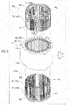
FIG. 3] FIG. 3 is an exploded perspective view of the stator according to the embodiment. - [
FIG. 4] FIG. 4 is a plan view illustrating the configuration of a stator core according to the embodiment. - [
FIG. 5] FIG. 5 is a sectional view illustrating the configuration of slot insulating paper according to the embodiment. - [
FIG. 6] FIG. 6 is a circuit diagram illustrating the connection configuration of a coil portion according to the embodiment. - [
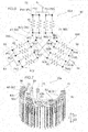
FIG. 7] FIG. 7 is a perspective view illustrating a part of a first coil assembly according to the embodiment. - [
FIG. 8] FIG. 8 is a cross-sectional view illustrating the configuration of a segment conductor according to the embodiment, in whichFIG. 8A illustrates an insulating coating andFIG. 8B illustrates an insulating portion. - [
FIG. 9] FIG. 9 illustrates the configuration of a general conductor according to the embodiment. - [
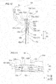
FIG. 10] FIG. 10 illustrates the configuration of a power conductor according to the embodiment. - [
FIG. 11] FIG. 11 is an enlarged view of a portion indicated by symbol E1 inFIG. 1 . - [
FIG. 12] FIG. 12 is a sectional view taken along the line 1000-1000 inFIG. 1 . - [
FIG. 13] FIG. 13 is a perspective view illustrating the configuration of a radially outer neutral point conductor according to the embodiment. - [
FIG. 14] FIG. 14 is an enlarged view of a portion indicated by symbol E2 inFIG. 1 . - [
FIG. 15] FIG. 15 is a perspective view illustrating the configuration of a radially inner neutral point conductor according to the embodiment. - [
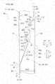
FIG. 16] FIG. 16 is a sectional view illustrating the configuration of a first facing surface and a second facing surface according to the embodiment. - [
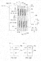
FIG. 17] FIG. 17 is a sectional view illustrating the position of arrangement of insulating members and joint portions according to the embodiment. - [
FIG. 18] FIG. 18 is a schematic view illustrating the areas of a first joint surface and a first inverse inclination surface and the areas of a second joint surface and a second inverse inclination surface according to the embodiment. - [
FIG. 19] FIG. 19 is a flowchart illustrating steps of manufacturing the stator according to the embodiment. - [
FIG. 20] FIG. 20 illustrates a step of disposing segment conductors in a slot according to the embodiment. - [
FIG. 21] FIG. 21 is a sectional view illustrating a step of disposing slot insulating paper in slots according to the embodiment. - [
FIG. 22] FIG. 22 is a sectional view, taken along the radial direction, illustrating a step of pressing segment conductors with a pressing jig and a wall portion according to the embodiment. - [
FIG. 23] FIG. 23 is a sectional view, as seen in plan, illustrating the step of pressing the segment conductors with the pressing jig and the wall portion according to the embodiment. - [
FIG. 24] FIG. 24 illustrates the configuration of a stator according to a first modification of the embodiment. - [
FIG. 25] FIG. 25 illustrates the configuration of a stator according to a second modification of the embodiment. - [
FIG. 26] FIG. 26 illustrates the configuration of a stator according to a third modification of the embodiment. - [
FIG. 27] FIG. 27 illustrates the configuration of a stator according to a fourth modification of the embodiment. - [
FIG. 28] FIG. 28 illustrates the configuration of a stator according to a fifth modification of the embodiment. - An embodiment of the present invention will be described below with reference to the drawings.
- The structure of a
stator 100 according to the present embodiment will be described with reference toFIGS. 1 to 16 . Thestator 100 has a circular ring shape centered on a center axis C1. Thestator 100 is an example of the "armature" in the claims. - The term "axial direction (center axis direction)" as used herein means the direction (Z direction) along the center axis C1 (rotational axis of a rotor 101) of the
stator 100 as illustrated inFIG. 1 . The term "circumferential direction" means the circumferential direction (A direction) of thestator 100. The term "radial direction" means the radial direction (R direction) of thestator 100. The term "radially inner side" means the direction (R1 direction) toward the center axis C1 of thestator 100. The term "radially outer side" means the direction (R2 direction) toward the outside of thestator 100. - The
stator 100 constitutes a part of a rotary electric machine together with therotor 101. The rotary electric machine is constituted as a motor, a generator, or a motor/generator, for example. As illustrated inFIG. 1 , thestator 100 is disposed on the radially outer side of therotor 101 which is provided with permanent magnets (not illustrated). That is, in the present embodiment, thestator 100 constitutes a part of a rotaryelectric machine 102 of an inner rotor type. - As illustrated in
FIG. 2 , thestator 100 includes astator core 10, slot insulatingpaper 20, and acoil portion 30. As illustrated inFIG. 3 , in addition, thecoil portion 30 includes afirst coil assembly 30a and asecond coil assembly 30b. In addition, thecoil portion 30 is composed of a plurality ofsegment conductors 40. Thestator core 10 is an example of the "armature core" in the claims. In addition, theslot insulating paper 20 is an example of the "slot insulating member" in the claims. - The
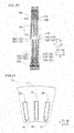
stator core 10 has a cylindrical shape centered on the center axis C1 (seeFIG. 1 ). In addition, thestator core 10 is formed by stacking a plurality of electromagnetic steel sheets (e.g. silicon steel sheets) in the axial direction, for example. As illustrated inFIG. 4 , thestator core 10 is provided with aback yoke 11 in a circular ring shape as seen in the axial direction and a plurality ofslots 12 provided on the radially inner side of theback yoke 11 to extend in the axial direction. Thestator core 10 includes a plurality ofteeth 13 provided on both sides of theslots 12 in the circumferential direction. - The
slots 12 are each a portion surrounded by awall portion 11a of theback yoke 11 provided on the radially outer side with respect to a firstother end surface 73, to be discussed later, and respective circumferential side surfaces 13a of twoteeth 13. Theslots 12 are each provided with anopening portion 12a provided on the radially inner side with respect to a second oneend surface 84, to be discussed later, to open on the radially inner side. In addition, theslots 12 open on both sides in the axial direction. Theteeth 13 are formed so as to project toward the radially inner side from theback yoke 11, and each have a projectingportion 13b formed at the distal end portion thereof on the radially inner side to constitute the openingportions 12a of theslots 12. - The
opening portion 12a has an opening width W1 in the circumferential direction. Here, the opening width W1 corresponds to the distance between the respective distal end portions of the projecting portions of the projectingportions 13b of theteeth 13. Meanwhile, a width W2 of a portion of theslot 12 in which thecoil portion 30 and theslot insulating paper 20 are disposed is larger than the opening width W1. That is, theslots 12 are constituted as semi-open slots. Here, the width W2 corresponds to the distance between the respective circumferential side surfaces 13a of theteeth 13 which are disposed on both sides of theslot 12. In addition, the width W2 of theslots 12 is generally constant over the radial direction. - As illustrated in
FIG. 5 , theslot insulating paper 20 is disposed between theteeth 13 and thesegment conductors 40. Here, in the present embodiment, theslot insulating paper 20 includes a jointportion cover portion 21. The jointportion cover portion 21 is configured to cover at least the radially inner side of ajoint portion 90, to be discussed later, of thesegment conductor 40 disposed closest to theopening portion 12a of theslot 12, among the plurality ofsegment conductors 40 which are disposed in parallel in the radial direction. The joint portion is an example of the "distal end portion" in the claims. - Particularly, the
slot insulating paper 20 is constituted of an insulating member in a sheet shape such as aramid paper and a polymer film, for example, and has a function of securing the insulation between the segment conductors 40 (coil portion 30) and thestator core 10. Theslot insulating paper 20 is disposed between thesegment conductors 40 and the circumferential side surfaces 13a of theteeth 13 and between thesegment conductor 40 disposed on the radially outermost side, among the plurality ofsegment conductors 40, and thewall portion 11a. In addition, as illustrated inFIG. 3 , theslot insulating paper 20 includes collar portions 22 (cuff portions) that project axially outward from theslot 12 on both sides in the axial direction and that are folded back to be formed. - The
slot insulating paper 20 is disposed so as to integrally cover the periphery of the plurality ofsegment conductors 40 which are disposed in parallel in the radial direction as seen in the direction of the arrow Z2. In other words, theslot insulating paper 20 covers both sides, in the circumferential direction, and both sides, in the radial direction, of slot housedportions segment conductors 40 which are disposed in parallel in the radial direction. Consequently, theslot insulating paper 20 can secure the insulation between thejoint portion 90 and thestator core 10. The slot housedportions - As illustrated in
FIGS. 2 and3 , thecoil portion 30 is formed by combining, in the axial direction, and joining thefirst coil assembly 30a, which is provided on one axial side (side in the direction of the arrow Z1), and thesecond coil assembly 30b, which is provided on the other axial side (side in the direction of the arrow Z2). Thefirst coil assembly 30a and thesecond coil assembly 30b are each formed in a circular ring shape about the center axis C1 (seeFIG. 1 ) as with thestator core 10. - The
coil portion 30 is constituted as a wave-wound coil, for example. In addition, thecoil portion 30 is constituted as an eight-turn coil, for example. That is, as illustrated inFIG. 5 , thecoil portion 30 is constituted with eightsegment conductors 40 disposed in parallel in the radial direction in eachslot 12. Thecoil portion 30 is supplied with three-phase AC power from a power source portion (not illustrated) so as to generate magnetic flux with a current flowing one way and the other in the axial direction and with a current flowing in the circumferential direction. - As illustrated in
FIG. 6 , thecoil portion 30 is connected through a Y connection of three phases. That is, thecoil portion 30 includes aU-phase coil portion 30U, a V-phase coil portion 30V, and a W-phase coil portion 30W. For example, thecoil portion 30 is provided with a plurality of neutral points N. Particularly, thecoil portion 30 is connected through a four-parallel connection (star connection). That is, theU-phase coil portion 30U is provided with four neutral point connection end portions NtU and four power line connection end portions PtU. The V-phase coil portion 30V is provided with four neutral point connection end portions NtV and four power line connection end portions PtV The W-phase coil portion 30W is provided with four neutral point connection end portions NtW and four power line connection end portions PtW. In the following description, the neutral point connection end portions and the power line connection end portions will be referred to simply as "neutral point connection end portions Nt" and "power line connection end portions Pt" in the case where U-phase, V-phase, and W-phase are not specifically differentiated from each other. - As illustrated in
FIG. 7 , thefirst coil assembly 30a includes: a plurality of (e.g. three) power line connection segment conductors 50 (hereinafter referred to as "power conductors 50") that serve as thesegment conductors 40; a plurality of (e.g. two) neutral point connection segment conductors 60 (hereinafter referred to as "neutral point conductors 60") that serve as thesegment conductors 40; and a plurality ofgeneral conductors 41 that are conductors (general segment conductors 40) that are different from thepower conductors 50 and theneutral point conductors 60, among the plurality ofsegment conductors 40, and that constitute thecoil portion 30. - As illustrated in
FIG. 3 , thesecond coil assembly 30b is constituted from a plurality ofgeneral conductors 41. Preferably, thesecond coil assembly 30b is constituted from only the plurality ofgeneral conductors 41, and all thepower conductors 50 and theneutral point conductors 60 provided in thestator 100 are provided in thefirst coil assembly 30a. - As illustrated in
FIG. 8A , thesegment conductor 40 is constituted as a rectangular conductive wire which has a generally rectangular cross-sectional surface. An insulatingcoating 40a which has a thickness t1 is provided on aconductor surface 40b of thesegment conductor 40. The thickness t1 of the insulatingcoating 40a is set to such a level that enables securing the insulation performance between different phases (insulation between coil end portions 43), for example. The insulatingcoating 40a has an insulation resistance r1. Particularly, the insulatingcoating 40a is constituted of a coating agent such as polyimide. Meanwhile, aconductor body 40c of thesegment conductor 40 is constituted of a metal material (conductive material) such as copper or aluminum, for example. WhileFIG. 8 illustrates components with size relationship such as thickness thereof exaggerated for illustration, the present invention is not limited thereto. - As illustrated in
FIG. 2 , thesegment conductor 40 includes the slot housedportions slots 12 and thecoil end portion 43. The slot housedportions slots 12 from the axial position of anend surface stator core 10. Thecoil end portion 43 means a portion formed to be continuous with the slot housedportions end surface stator core 10. In addition, thecoil end portion 43 has an offset portion shaped to be bent in the axial direction and offset in the radial direction at the bent portion. - As illustrated in
FIG. 9 , thegeneral conductor 41 includes a pair of slot housedportions different slots 12 and acoil end portion 43 that connects between the pair of slot housedportions general conductor 41 has a generally U-shape or a generally J-shape as seen from the radially inner side. The slot housedportions portions power conductors 50 and the slot housedportions neutral point conductors 60 are configured similarly to the slot housedportions general conductors 41, and therefore are not described. - Here, the coil pitch of the
general conductor 41 is six. That is, the pair of slot housedportions slots 12 away from each other in the circumferential direction. That is, five slots are provided between theslot 12 in which the slot housedportion 42a of thegeneral conductor 41 is disposed and theslot 12 in which the slot housedportion 42b is disposed. - In the present embodiment, in addition, the pair of slot housed
portions portion 42a is longer than an axial length L2 of the slot housedportion 42b. The axial length L1 (L2) of the slot housedportion 42a (42b) means the length from a distal end 75 (85) to the axial position corresponding to theaxial end surface 10a (10b) of thestator core 10. In addition, the axial lengths L1 and L2 are smaller than an axial length L3 of thestator core 10. The axial length L3 of thestator core 10 means the distance (interval) between the axial end surfaces 10a and 10b. For example, the axial length L1 is longer than half the axial length L3, and the axial length L2 is shorter than half the axial length L3. - In addition, the plurality of
general conductors 41 include firstgeneral conductors 41a disposed on one axial side (side in the direction of the arrow Z1) with respect to thestator core 10 and included in thefirst coil assembly 30a, and secondgeneral conductors 41b disposed on the other axial side (side in the direction of the arrow Z2) with respect to thestator core 10 and included in thesecond coil assembly 30b. - In the
power conductor 50, as illustrated inFIG. 6 , a plurality of (e.g. four) power line connection end portions Pt for the same phase are electrically connected to each other, and the plurality of power line connection end portions Pt which are connected to each other and apower terminal member 51 are electrically connected to each other. Thepower conductors 50 have a function of introducing power from a power source portion (not illustrated) to thecoil portion 30. - Particularly, as illustrated in
FIG. 7 , thepower conductor 50 includes a radiallyouter power conductor 52 to be disposed on the axially outer side of thestator core 10 and a radiallyinner power conductor 53 to be disposed on the radially inner side. In other words, thepower conductor 50 is formed in a bifurcated shape. - Here, in the present embodiment, as illustrated in
FIG. 10 , the radiallyouter power conductor 52 and thepower terminal member 51 are electrically connected to each other by alead wire 54. In addition, the radiallyinner power conductor 53 and thepower terminal member 51 are electrically connected to each other by alead wire 54. The radiallyouter power conductor 52 and the radiallyinner power conductor 53 are electrically connected to each other via thepower terminal member 51 and thelead wires 54. In addition, thelead wires 54 are formed from a stranded wire (conductor), for example, with an insulatingtube 51a disposed at the outer periphery thereof. - The radially
outer power conductor 52 includes two slot housedportions 42a, two power linecoil end portions 52a that constitute two power line connection end portions Pt and that are led out from the slot housedportions 42a in the axial direction, and aconductor plate 52b joined to the two power linecoil end portions 52a to be electrically connected thereto. For example, theconductor plate 52b is joined to the radially outer side of the two power linecoil end portions 52a, and thelead wire 54 is joined to the radially outer side of theconductor plate 52b. - The two power line
coil end portions 52a and theconductor plate 52b are connected to each other by being welded at weldedportions 52c. In addition, theconductor plate 52b and thelead wire 54 are connected to each other by being brazed or welded at ajoint portion 52d. For example, the welding is implemented through any of resistance welding, arc welding, laser welding, and high-energy beam welding. - Here, as illustrated in
FIG. 11 , a spacing D1 in the radial direction between the weldedportion 52c and thejoint portion 52d (conductor plate 52b) and anend surface 43a, on the radially outer side, of thecoil end portion 43 of thegeneral conductor 41 is equal to or less than twice a width W11 of the cross-sectional surface (seeFIG. 8 ) of the segment conductor 40 (preferably equal to or less than the width W11). For example, no welding tool space is provided between the weldedportion 52c and thejoint portion 52d and thecoil end portion 43. - As illustrated in
FIG. 10 , the radiallyinner power conductor 53 includes two slot housedportions 42b, two power linecoil end portions 53a that constitute two power line connection end portions Pt and that are led out from the slot housedportions 42b in the axial direction, and aconductor plate 53b joined to the two power linecoil end portions 53a to be electrically connected thereto. For example, theconductor plate 53b is joined to the axially outer side (side in the direction of the arrow Z1) of the two power linecoil end portions 53a, and thelead wire 54 is joined to the axially outer side (side in the direction of the arrow Z1) of theconductor plate 53b. - The two power line
coil end portions 53a and theconductor plate 53b are connected to each other by being welded atjoint portions 53c. In addition, theconductor plate 53b and thelead wire 54 are connected to each other by being welded at a weldedportion 53d. Here, a spacing D2 in the axial direction between thejoint portion 53c and the weldedportion 53d (conductor plate 53b) and anend surface 43b, on one axial side, of thecoil end portion 43 of thegeneral conductor 41 is equal to or less than twice the width W11 of the cross-sectional surface (seeFIG. 8 ) of the segment conductor 40 (preferably equal to or less than the width W11). - The slot pitch of the radially
outer power conductor 52 is one for a portion formed from the slot housedportions 42a and theconductor plate 52b, and zero if only the slot housedportions 42a are considered as thesegment conductors 40. Meanwhile, the slot pitch of the radiallyinner power conductor 53 is one for a portion formed from the slot housedportions 42b and theconductor plate 53b, and zero if only the slot housedportions 42b are considered as thesegment conductors 40. That is, the slot pitch of thepower conductor 50 is different from the slot pitch (6) of thegeneral conductor 41. - As illustrated in
FIG. 7 , theneutral point conductors 60 include a radially outerneutral point conductor 61 and a radially innerneutral point conductor 62. As illustrated inFIG. 6 , the radially outerneutral point conductor 61 and the radially innerneutral point conductor 62 each include a neutral point N, at which the neutral point connection end portions NtU of theU-phase coil portion 30U, the neutral point connection end portions NtV of the V-phase coil portion 30V, and the neutral point connection end portions NtW of the W-phase coil portion 30W are electrically connected to each other. - As illustrated in
FIG. 13 , the radially outerneutral point conductor 61 includes two U-phase/W-phase neutralpoint segment conductors 61a and two V-phase neutralpoint segment conductors 61b. The U-phase/W-phase neutralpoint segment conductors 61a each include a slot housedportion 42a for U-phase to be connected to thegeneral conductor 41 for U-phase of three-phase AC, a slot housedportion 42a for W-phase to be connected to thegeneral conductor 41 for W-phase, and two neutral pointcoil end portions 61c that each connect between the slot housedportion 42a for U-phase and the slot housedportion 42a for W-phase. The neutral pointcoil end portions 61c are each formed to be continuous with the slot housedportion 42a for U-phase, and formed to be continuous with the slot housedportion 42a for W-phase. - The U-phase/W-phase neutral
point segment conductors 61a are each formed in a generally U-shape (generally C-shape) as seen from the radially inner side. The V-phase neutralpoint segment conductors 61b are each formed in a generally straight shape as seen from the radially inner side. - As illustrated in
FIG. 14 , the neutral pointcoil end portions 61c are formed along the circumferential direction on the radially outer side of thecoil end portion 43 of thegeneral conductor 41. The neutral pointcoil end portions 61c are formed in a generally arcuate shape as seen in the direction of the arrow Z2. - In addition, the slot pitch of one of the two U-phase/W-phase neutral
point segment conductors 61a is nine. Meanwhile, the slot pitch of the other of the two U-phase/W-phase neutralpoint segment conductors 61a is seven. That is, the U-phase/W-phase neutralpoint segment conductors 61a have a slot pitch that is different from the slot pitch (6) of thegeneral conductor 41. One of the two U-phase/W-phase neutralpoint segment conductors 61a is disposed on the axially outer side (side in the direction of the arrow Z1) of the other. - As illustrated in
FIG. 13 , the V-phase neutralpoint segment conductors 61b each include a slot housedportion 42a for V-phase to be connected to thegeneral conductor 41 for V-phase and a neutral pointcoil end portion 61d. The neutral pointcoil end portion 61d is formed so as to project toward the axially outer side (in the direction of the arrow Z1) from the slot housedportion 42a. Each of the two neutral pointcoil end portions 61d is joined to the two neutral pointcoil end portions 61c to be electrically joined thereto. - Specifically, as illustrated in
FIG. 14 , the two neutral pointcoil end portions 61d are welded at weldedportions 61e to the radially outer side of the two neutral pointcoil end portions 61c in an arcuate shape. Consequently, in the radially outerneutral point conductor 61, the neutral point connection end portions NtU of theU-phase coil portion 30U, the neutral point connection end portions NtV of the V-phase coil portion 30V, and the neutral point connection end portions NtW of the W-phase coil portion 30W are electrically connected to each other. A spacing D3 between the weldedportions 61e (an end surface of the neutral pointcoil end portions 61c on the radially inner side) and anend surface 43c, on the radially outer side, of thecoil end portion 43 of thegeneral conductor 41 is equal to or less than twice the width W11, along the radial direction, of the cross-sectional surface of the segment conductor 40 (preferably equal to or less than the width W11). - As illustrated in
FIG. 15 , the radially innerneutral point conductor 62 includes two U-phase/W-phase neutralpoint segment conductors 62a and two V-phase neutralpoint segment conductors 62b. The U-phase/W-phase neutralpoint segment conductors 62a each include a slot housedportion 42b for U-phase to be connected to thegeneral conductor 41 for U-phase of three-phase AC, a slot housedportion 42b for W-phase to be connected to thegeneral conductor 41 for W-phase, and a neutral pointcoil end portion 62c that connects between the slot housedportion 42b for U-phase and the slot housedportion 42b for W-phase. The neutral pointcoil end portions 62c are each formed to be continuous with the slot housedportion 42b for U-phase, and formed to be continuous with the slot housedportion 42b for W-phase. - The U-phase/W-phase neutral
point segment conductors 62a are each formed in a generally U-shape (generally C-shape) as seen from the radially inner side. The V-phase neutralpoint segment conductors 62b are each formed in a generally straight shape as seen from the radially inner side. - As illustrated in
FIG. 7 , the neutral pointcoil end portions 62c are formed on the radially inner side of thecoil end portion 43 of thegeneral conductor 41 to project toward the axially outer side with respect to thecoil end portion 43 of thegeneral conductor 41. The neutral pointcoil end portions 62c are disposed in proximity to the axially outer side of thecoil end portion 43 of thegeneral conductor 41, and formed along the circumferential direction as seen in the axial direction. - In addition, the slot pitch of one of the two U-phase/W-phase neutral
point segment conductors 62a is nine. Meanwhile, the slot pitch of the other of the two U-phase/W-phase neutralpoint segment conductors 62a is seven. That is, the U-phase/W-phase neutralpoint segment conductors 62a have a slot pitch that is different from the slot pitch (6) of thegeneral conductor 41. One of the two U-phase/W-phase neutralpoint segment conductors 62a is disposed on the radially outer side of the other. - The V-phase neutral
point segment conductors 62b each include a slot housedportion 42b for V-phase to be connected to thegeneral conductor 41 for V-phase and a neutral pointcoil end portion 62d. The neutral pointcoil end portion 62d is formed so as to project toward the axially outer side (in the direction of the arrow Z1) from the slot housedportion 42b. Each of the two neutral pointcoil end portions 62d is joined to the two neutral pointcoil end portions 62c to be electrically joined thereto. - Specifically, as illustrated in
FIG. 15 , the two neutral pointcoil end portions 62d are welded at weldedportions 62e to the axially outer side of the two neutral pointcoil end portions 62c in an arcuate shape. Consequently, in the radially innerneutral point conductor 62, the neutral point connection end portions NtU of theU-phase coil portion 30U, the neutral point connection end portions NtV of the V-phase coil portion 30V, and the neutral point connection end portions NtW of the W-phase coil portion 30W are electrically connected to each other. As illustrated inFIG. 12 , a spacing D4 between the weldedportions 62e (an end surface of the neutral pointcoil end portions 62d on the axially inner side) and anend surface 43d, on the axially outer side, of thecoil end portion 43 of thegeneral conductor 41 is equal to or less than twice the width W11, along the radial direction, of the cross-sectional surface of the segment conductor 40 (preferably equal to or less than the width W11). - Here, in the present embodiment, as illustrated in
FIG. 16 , a first slot housedportion 71 which is the slot housedportion segment conductor 40 which constitutes thefirst coil assembly 30a, among the plurality ofsegment conductors 40, and a second slot housedportion 81 which is the slot housedportion segment conductor 40 which constitutes thesecond coil assembly 30b and which faces the first segment conductor 70 in the axial direction are joined to each other at thejoint portion 90 in theslot 12 of thestator core 10. - The first slot housed
portion 71 includes a first facingsurface 72 that directs to the radially inner side (side in the direction of the arrow R1) and that faces the second slot housedportion 81 and a firstother end surface 73 that faces the radially outer side (side in the direction of the arrow R2). Meanwhile, the second slot housedportion 81 includes a second facingsurface 82 that directs to the radially outer side and that faces the first facingsurface 72 and a secondother end surface 83 that directs to the radially outer side and that is continuous with the second facingsurface 82. At least a part of the first facingsurface 72 and at least a part of the second facingsurface 82 are joined to each other, and the firstother end surface 73 is disposed so as to project toward the radially outer side with respect to the secondother end surface 83. - In addition, the first slot housed
portion 71 includes a first oneend surface 74 that is provided on the opposite side, in the radial direction, of the firstother end surface 73 and that is continuous with the first facingsurface 72. The second slot housedportion 81 includes a second oneend surface 84 that is provided on the opposite side, in the radial direction, of the secondother end surface 83 and that directs to the radially inner side. The second oneend surface 84 is disposed so as to project toward the radially inner side with respect to the first oneend surface 74. - Here, the
joint portion 90 is a portion of thecoil portion 30 illustrated inFIG. 16 , includes the first facingsurface 72 and the second facingsurface 82, and includes a portion of the first slot housedportion 71 from thedistal end 75 to aboundary point 76 between the first facingsurface 72 and the first oneend surface 74 and a portion of the second slot housedportion 81 from thedistal end 85 to aboundary point 86 between the second facingsurface 82 and the secondother end surface 83. - In the present embodiment, a second stepped
portion 111 is formed between thedistal end 75 of the first slot housedportion 71 and theboundary point 86 of the second slot housedportion 81, which is the boundary portion between the firstother end surface 73 and the secondother end surface 83. Meanwhile, a first steppedportion 112 is formed between theboundary point 76 of the first slot housedportion 71 and thedistal end 85 of the second slot housedportion 81, which is the boundary portion between the first oneend surface 74 and the second oneend surface 84. Specifically, in the second stepped portion 111 a step is formed to be dented inward of thesegment conductor 40 from the firstother end surface 73 toward the secondother end surface 83. Meanwhile, in the first stepped portion 112 a step is formed to be dented inward of thesegment conductor 40 from the second oneend surface 84 toward the first oneend surface 74. - In addition, a first deviation width d1 which is the width of the deviation between a radial position P1 of the first
other end surface 73 and a radial position P2 of the secondother end surface 83 is larger than the thickness t1 of the insulatingcoating 40a of thesegment conductor 40, for example. The first deviation width d1 corresponds to the height of the step of the second steppedportion 111. - Particularly, the first deviation width d1 is set to such a level that the
segment conductor 40 is not pressed in the direction of moving the first facingsurface 72 and the second facingsurface 82 away from each other, or to such a level that a pressing force is reduced when the first slot housedportion 71 or the second slot housedportion 81 is pressed by apressing jig 200, to be discussed later, and thewall portion 11a, even in the case where the first slot housedportion 71 or the second slot housedportion 81 is elastically deformed. - For example, as illustrated in
FIG. 17 , a clearance CL1 is formed in the radial direction between thewall portion 11a and the secondother end surface 83 of the second slot housedportion 81 disposed on the radially outermost side. Meanwhile, a clearance CL2 is formed in the radial direction between thepressing jig 200 and the first oneend surface 74 of the first slot housedportion 71 disposed on the radially innermost side during manufacture of thestator 100. - In the present embodiment, in addition, as illustrated in
FIG. 16 , the first deviation width d1 is equal to a second deviation width d2 which is the width of the deviation between a radial position P3 of the first oneend surface 74 and a radial position P4 of the second one end surface 84 (height of the step of the first stepped portion 112). That is, a width W21, in the radial direction, of the first slot housedportion 71 is generally equal to a width W22, in the radial direction, of the second slot housedportion 81. In addition, the first slot housedportion 71 is disposed as displaced toward the radially outer side with respect to the second slot housedportion 81. - As illustrated in
FIG. 17 , a plurality of (e.g. eight) first slot housedportions 71 and second slot housedportions 81 are disposed adjacent to each other in the radial direction in theslot 12. That is, the plurality of first slot housedportions 71 are disposed in parallel in the radial direction, and the plurality of second slot housedportions 81 are disposed in parallel in the radial direction. - In the
slot 12, the first facing surface 72 (joint portion 90) of one first slot housedportion 71, among the plurality of first slot housedportions 71, is disposed at a different position in the center axis direction from a different first facing surface 72 (joint portion 90) that is adjacent in the radial direction. In theslot 12, in addition, the second facingsurface 82 of one second slot housedportion 81, among the plurality of second slot housedportions 81, is disposed at a different position in the center axis direction from a different second facingsurface 82 that is adjacent in the radial direction. That is, in the present embodiment, an axial position P11 of thejoint portion 90 which is constituted from the first facingsurface 72 and the second facingsurface 82 is different from an axial position P12 of thejoint portion 90 which is constituted from a different first facingsurface 72 and a different second facingsurface 82 that are adjacent in the radial direction. - In other words, the first slot housed
portions 71 and the second slot housedportions 81 are disposed in a staggered manner along the radial direction at the axial positions P11 and P12. The firstother end surface 73 is disposed (offset) so as to project toward the radially outer side with respect to the corresponding secondother end surface 83 at each of the plurality ofjoint portions 90. In addition, the second oneend surface 84 is disposed (offset) so as to project toward the radially inner side with respect to the corresponding first oneend surface 74 at each of the plurality ofjoint portions 90. Consequently, a clearance CL3 in the radial direction is formed between the first oneend surface 74 and the secondother end surface 83 in the radial direction. - Here, in the present embodiment, as illustrated in
FIG. 16 , the first facingsurface 72 of the first slot housedportion 71 and the second facingsurface 82 of the second slot housedportion 81 are formed so as to be inclined with respect to the axial direction. Specifically, the first facingsurface 72 is constituted as an end surface inclined with respect to the axial direction from thedistal end 75 of the first slot housedportion 71 in the direction of the arrow E1. In addition, the first facingsurface 72 is not provided with the insulatingcoating 40a. The second facingsurface 82 is constituted as an end surface inclined from thedistal end 85 of the second slot housedportion 81 in the direction of the arrow E2. In addition, the second facingsurface 82 is not provided with the insulatingcoating 40a. The direction of the arrow E1 means a direction from thedistal end 75 toward theboundary point 76 between the first facingsurface 72 and the first oneend surface 74. The direction of the arrow E2 means a direction from thedistal end 85 toward theboundary point 86 between the second facingsurface 82 and the secondother end surface 83. - The first facing
surface 72 and the second facingsurface 82 are each formed such that the sectional surface thereof taken along the radial direction has an S-shape. In other words, the first facingsurface 72 is formed into a recessed and projected shape to be recessed and projected in the radial direction, and the second facingsurface 82 is formed into a recessed and projected shape, corresponding to the recessed and projected shape of the first facingsurface 72, to be recessed and projected in the radial direction. The first facingsurface 72 which has an S-shape (recessed and projected shape) and the second facingsurface 82 which has an S-shape (recessed and projected shape) are disposed in theslot 12 with the first facingsurface 72 and the second facingsurface 82 engaged with each other in the radial direction. - Here, in the present embodiment, a part of the first facing
surface 72 and a part of the second facingsurface 82 are joined to each other using ajoint material 130. Particularly, the first facingsurface 72 includes a firstjoint surface 72a to be joined to the second facingsurface 82 and a firstinverse inclination surface 72b formed to be continuous with the firstjoint surface 72a and inclined in the direction (direction of the arrow E12) which is opposite to the direction (direction of the arrow E11) in which the firstjoint surface 72a is inclined with respect to the axial direction (axis that is parallel to the center axis C1). In addition, the firstjoint surface 72a and the firstinverse inclination surface 72b are each formed as a generally flat surface, and the firstjoint surface 72a and the firstinverse inclination surface 72b form a bent shape. In addition, the second facingsurface 82 includes a secondjoint surface 82a to be joined to the firstjoint surface 72a and a secondinverse inclination surface 82b formed to be continuous with the secondjoint surface 82a and inclined in the direction (direction of the arrow E22) which is opposite to the direction (direction of the arrow E21) in which the secondjoint surface 82a is inclined with respect to the axial direction. - The
joint material 130 is disposed between the firstjoint surface 72a and the secondjoint surface 82a, and joins the firstjoint surface 72a and the secondjoint surface 82a to be electrically connected to each other. Specifically, thejoint material 130 contains a conductive material such as silver or copper. Preferably, thejoint material 130 is a joint material (silver nano paste) in a paste form in which a solvent contains conductive particles which are metal particles obtained by making silver finer to the nanometer level. In addition, thejoint material 130 contains a member (resin member) to be volatilized when heated, and has a function of bringing the firstjoint surface 72a and the secondjoint surface 82a closer to each other with the volume of thejoint material 130 decreased when the member to be volatilized is heated. - In the present embodiment, an inclination angle θ2 of the first
inverse inclination surface 72b and the secondinverse inclination surface 82b with respect to the axial direction is smaller than an inclination angle θ1 of the firstjoint surface 72a and the secondjoint surface 82a with respect to the axial direction. Consequently, it is possible to prevent a minimum width W31, in the radial direction, of the first slot housedportion 71 on the root side (side in the direction of the arrow Z1) with respect to the firstjoint surface 72a from being small. - In addition, as illustrated in
FIG. 18 , an area S11 of the firstjoint surface 72a is larger than an area S12 of the firstinverse inclination surface 72b, and an area S21 of the secondjoint surface 82a is larger than an area S22 of the secondinverse inclination surface 82b. That is, a length L11 of the firstjoint surface 72a along the direction of the arrow E11 is longer than a length L12 of the firstinverse inclination surface 72b along the direction of the arrow E12, and a length L21 of the secondjoint surface 82a along the direction of the arrow E21 is longer than a length L22 of the secondinverse inclination surface 82b along the direction of the arrow E21. - As illustrated in
FIG. 16 , the first facingsurface 72 includes a first spaced facingsurface 72c formed to be continuous with the firstinverse inclination surface 72b on the opposite side from the firstjoint surface 72a and disposed as spaced from the second facingsurface 82. In addition, the second facingsurface 82 includes a second spaced facingsurface 82c formed to be continuous with the secondinverse inclination surface 82b on the opposite side from the secondjoint surface 82a and disposed as spaced from the first facingsurface 72. - Particularly, the first spaced facing
surface 72c is inclined in the direction of the arrow E13 which is opposite to the firstinverse inclination surface 72b with respect to the axial direction (axis that is parallel to the center axis C1). In addition, the first spaced facingsurface 72c is smoothly connected to the firstinverse inclination surface 72b with the connection portion formed in an arcuate shape (round shape). The second spaced facingsurface 82c is disposed to face the first spaced facingsurface 72c, and a clearance CL4 is provided between the first spaced facingsurface 72c and the second spaced facingsurface 82c. - In addition, the first facing
surface 72 and the second facingsurface 82 are each formed such that the sectional surface thereof taken along the radial direction has an asymmetrical shape with respect to a center point C2 of the first facingsurface 72. Specifically, the first facingsurface 72 and the second facingsurface 82 are configured such that, in the case where the center point C2 is defined as the middle point between thedistal end 75 and theboundary point 76 and the first facingsurface 72 is rotated by 180 degrees about the center point C2, the shape of the first facingsurface 72 which has been rotated and the shape of the second facingsurface 82 do not coincide with each other. Particularly, an asymmetrical shape is achieved since the first facingsurface 72 includes the firstjoint surface 72a, the firstinverse inclination surface 72b, and the first spaced facingsurface 72c which are provided in this order from thedistal end 75 of the first slot housedportion 71, while the second facingsurface 82 includes the second spaced facingsurface 82c, the secondinverse inclination surface 82b, and the secondjoint surface 82a which are provided in this order from thedistal end 85 of the second slot housedportion 81. - In addition, the
distal end 75 of the first slot housedportion 71 and thedistal end 85 of the second slot housedportion 81 are each formed as a flat surface that is orthogonal to the axial direction. Particularly, the distal ends 75 and 85 are provided between the first facingsurface 72 and the firstother end surface 73 and between the second facingsurface 82 and the secondother end surface 83, respectively, to have a chamfered shape. - Here, in the present embodiment, the
coil portion 30 is provided with insulatingportions 120. As illustrated inFIG. 17 , an insulatingportion 120 is provided on theconductor surface 40b (seeFIG. 8B ) of onesegment conductor 40, among the plurality of segment conductors 40 (general conductors 41,power conductors 50, and neutral point conductors 60) which are disposed in parallel, at an axial position corresponding to thejoint portion 90 of a different segment conductor 40 (hereinafter thisjoint portion 90 will be referred to as an "adjacentjoint portion 90") disposed adjacent to the onesegment conductor 40 in the radial direction. The insulatingportion 120 has a thickness t2 which is larger than the thickness t1 of the insulatingcoating 40a of the adjacent joint portion 90 (different segment conductor 40). Consequently, an insulation resistance r2 of the insulatingportion 120 is higher than the insulation resistance r1 of the insulatingcoating 40a alone. In addition, the insulatingportions 120 are provided at the positions P11 and P12 (seeFIG. 17 ), in the center axis direction, at which the adjacentjoint portion 90 is present. The adjacentjoint portion 90 is an example of the "adjacent joint portion" in the claims. In addition, the insulation resistance r1 is an example of the "first insulation resistance" in the claims. In addition, the insulation resistance r2 is an example of the "second insulation resistance" in the claims. - Specifically, as illustrated in
FIG. 8B , the insulatingportion 120 includes the insulatingcoating 40a which is provided on theconductor surface 40b and which has the thickness t1, and an insulatingmember 121 that covers the insulatingcoating 40a and that has a function of insulating thesegment conductor 40 and the adjacentjoint portion 90 from each other. A thickness t3 of the insulatingmember 121 is smaller than the thickness t1. That is, the thickness t2 is larger than the thickness t1, and less than twice the thickness t1. - Particularly, the insulating
member 121 is formed in a sheet shape. For example, the insulatingmember 121 contains the same material as the material contained in the insulatingcoating 40a. Preferably, the insulatingmember 121 contains an insulation material such as polyimide. The insulatingmember 121 in a sheet shape is wound around the outer periphery of the insulatingcoating 40a of thesegment conductor 40 for at least one round (e.g. more than one round and less than two rounds). For example, the insulatingmember 121 in a sheet shape is fixed to the insulatingcoating 40a using an adhesive with insulation properties etc. - As illustrated in
FIG. 9 , the insulating portion 120 (insulating member 121) is provided on the slot housedportion 42a, of the slot housedportions member 121 is provided on each of the plurality of slot housedportions 42a, while the insulatingmember 121 is not provided on the plurality of slot housedportions 42b. - A length L31 of the insulating portion 120 (insulating member 121) in the axial direction is equal to or more than an insulation creepage distance Dc along the center axis direction from the adjacent
joint portion 90, and less than the length L3 of theslot 12 in the axial direction. Particularly, the length L31 of the insulating portion 120 (insulating member 121) is set to be at least equal to or more than the insulation creepage distance Dc with respect to the closer one of thedistal end 75 of the first slot housedportion 71 and thedistal end 85 of the second slot housedportion 81 which are adjacent in the radial direction. That is, as illustrated inFIG. 17 , the insulation properties are secured by securing the insulation creepage distance Dc between the first facingsurface 72 and the second facingsurface 82, which are not provided with the insulatingcoating 40a, and the adjacent slot housedportion 42a. - Next, a method of manufacturing the
stator 100 according to the present embodiment will be described.FIG. 19 is a flowchart illustrating the method of manufacturing thestator 100. - First, in step S1, a plurality of
segment conductors 40 are prepared. Specifically, thepower conductors 50 which constitute the power line connection end portions Pt for the individual phases of thecoil portion 30 which is connected through a Y connection, theneutral point conductors 60 which constitute the neutral point connection end portions Nt for the individual phases of thecoil portion 30, and thegeneral conductors 41 which constitute the other portions of thecoil portion 30 are prepared. - For example, as illustrated in
FIG. 8A , an insulatingcoating 40a made of an insulation material such as polyimide is formed (coated) on theconductor surface 40b in a rectangular shape which is made of a conductive material such as copper. After that, the conductor (rectangular conductive wire) on which the insulatingcoating 40a is formed is shaped using a shaping jig (not illustrated) to form the general conductors 41 (seeFIG. 9 ), the radiallyouter power conductors 52 and the radially inner power conductors 53 (seeFIG. 10 ) for forming thepower conductors 50, two U-phase/W-phase neutralpoint segment conductors 61a and two V-phase neutralpoint segment conductors 61b for forming the radially outer neutral point conductor 61 (seeFIG. 13 ), and two U-phase/W-phase neutralpoint segment conductors 62a and two V-phase neutralpoint segment conductors 62b for forming the radially inner neutral point conductor 62 (seeFIG. 15 ). - Particularly, as illustrated in
FIG. 9 , thegeneral conductors 41 are each formed by forming a pair of slot housedportions coil end portion 43 that connects between the pair of slot housedportions - In the present embodiment, as illustrated in
FIG. 10 , thepower conductors 50 are each formed by electrically connecting the radiallyouter power conductor 52 and the radiallyinner power conductor 53 to each other by electrically joining (performing a power conductor joint step) the radiallyouter power conductor 52 and the radiallyinner power conductor 53 to the commonpower terminal member 51 via thelead wires 54. Thepower conductors 50 are formed for the respective phases. - Particularly, the welded
portions 52c are formed by welding (joining) two power linecoil end portions 52a, which constitute two power line connection end portions Pt and which are led out in the axial direction from two slot housedportions 42a, and theconductor plate 52b to each other, so that the radiallyouter power conductor 52 is formed. In addition, thejoint portions 53c are formed by brazing or welding (joining) two power linecoil end portions 53a, which constitute two power line connection end portions Pt and which are led out in the axial direction from the slot housedportions 42b, and theconductor plate 53b to each other, so that the radiallyinner power conductor 53 is formed. For example, the welding is implemented through any of resistance welding, arc welding, laser welding, and high-energy beam welding. Consequently, the radiallyouter power conductor 52 and the radiallyinner power conductor 53 with a slot pitch of one (in the case where theconductor plates conductor plates - In addition, a plurality of
lead wires 54 with the insulatingtube 51a attached to the outer periphery thereof and which are joined to thepower terminal member 51 are prepared. Thelead wire 54 is welded to the radially outer side of theconductor plate 52b of the radiallyouter power conductor 52 to form thejoint portion 52d. In addition, thelead wire 54 is welded to the axially outer side (side in the direction of the arrow Z1) of theconductor plate 53b of the radiallyinner power conductor 53 to form the weldedportion 53d. Consequently, thepower conductors 50 which have a bifurcated shape in which the radiallyouter power conductor 52 is disposed on the radially outer side and the radiallyinner power conductor 53 is disposed on the radially inner side are formed. - As illustrated in
FIG. 13 , the U-phase/W-phase neutralpoint segment conductors 61a which each include the neutral pointcoil end portion 61c which connects between the slot housedportion 42a for U-phase and the slot housedportion 42a for W-phase are shaped. In addition, the U-phase/W-phase neutralpoint segment conductors 61a are shaped such that the slot pitch of one of the two U-phase/W-phase neutralpoint segment conductors 61a is nine while the slot pitch of the other is seven. One of the two U-phase/W-phase neutralpoint segment conductors 61a is disposed on the axially outer side (side in the direction of the arrow Z1) of the other. The V-phase neutralpoint segment conductors 61b which each include the slot housedportion 42a for V-phase and the neutral pointcoil end portion 61d are shaped. - After that, the welded
portions 61e are formed by welding (performing a neutral point conductor joint step) the two neutral pointcoil end portions 61d on end surfaces of the two neutral pointcoil end portions 61c on the radially outer side (to each other). Consequently, the radially outer neutral point conductor 61 (neutral point conductor 60) in which the neutral point connection end portions NtU of theU-phase coil portion 30U, the neutral point connection end portions NtV of the V-phase coil portion 30V, and the neutral point connection end portions NtW of the W-phase coil portion 30W are electrically connected to each other is formed. - As illustrated in
FIG. 15 , the U-phase/W-phase neutralpoint segment conductors 62a which each include the neutral pointcoil end portion 62c which connects between the slot housedportion 42b for U-phase and the slot housedportion 42b for W-phase are shaped. In addition, the U-phase/W-phase neutralpoint segment conductors 62a are shaped such that the slot pitch of one of the two U-phase/W-phase neutralpoint segment conductors 62a is nine while the slot pitch of the other is seven. The V-phase neutralpoint segment conductors 62b which each include the slot housedportion 42b for V-phase and the neutral pointcoil end portion 62d are shaped. - After that, the welded
portions 62e are formed by welding the two neutral pointcoil end portions 62d on end surfaces of the two neutral pointcoil end portions 62c on the axially outer side (to each other). Consequently, the radially inner neutral point conductor 62 (neutral point conductor 60) in which the neutral point connection end portions NtU of theU-phase coil portion 30U, the neutral point connection end portions NtV of the V-phase coil portion 30V, and the neutral point connection end portions NtW of the W-phase coil portion 30W are electrically connected to each other is formed. - In the present embodiment, in step S2 (see
FIG. 19 ), the insulatingportion 120 which has the thickness t2 which is larger than the thickness t1 of the insulatingcoating 40a of thejoint portion 90 is provided on theconductor surface 40b of a portion of thesegment conductor 40 that is different from afirst surface 172 and asecond surface 182. Consequently, the insulation resistance r2 of the insulatingportion 120 is higher than the insulation resistance r1 of the insulatingcoating 40a alone. - As illustrated in
FIG. 9 , the insulatingportion 120 is formed by attaching the insulatingmember 121 to the slot housedportion 42a, of the pair of slot housedportions member 121 is attached to each of the slot housedportions 42a of thegeneral conductors 41, the slot housedportions 42a of the radiallyouter power conductors 52, and the slot housedportions 42a of the radially outerneutral point conductor 61. - Particularly, as illustrated in
FIG. 8B , the insulatingmember 121 in a sheet shape which has the thickness t3 which is smaller than the thickness t1 is wound around the slot housedportion 42a for one round or more (e.g. more than one round and less than two rounds) to be fixed. Consequently, in the case where the number of times of winding is one (one round), the insulatingportion 120 which has the thickness t2 (= t1 + t3) which is larger than the thickness t1 is formed on the slot housedportion 42a. - In step S3, as illustrated in
FIG. 3 , thefirst coil assembly 30a and thesecond coil assembly 30b in a circular ring shape which are composed of a plurality ofsegment conductors 40 are formed. - In the present embodiment, as illustrated in
FIGS. 3 and20 , thefirst coil assembly 30a and thesecond coil assembly 30b in a circular ring shape which are composed of a plurality ofsegment conductors 40 are formed such that the insulatingportion 120 of onesegment conductor 40 is positioned at a position adjacent, in the radial direction, to thejoint portion 90 of adifferent segment conductor 40 disposed adjacent to the onesegment conductor 40 in the radial direction. While only some (two) of the plurality of insulatingportions 120 are illustrated as hatched for illustration inFIG. 3 , all the slot housedportions 42a are provided with the insulatingportions 120 in the present embodiment. - Specifically, as illustrated in
FIG. 3 , thefirst coil assembly 30a in a circular ring shape is formed such that the plurality ofgeneral conductors 41, thepower conductors 50 for the three phases, and the radially outerneutral point conductor 61 and the radially innerneutral point conductor 62 have an arrangement relationship that is generally similar to that of such conductors at the time when the conductors are disposed in the plurality of slots 12 (with thestator 100 in the completed state). In addition, thesecond coil assembly 30b in a circular ring shape is formed such that the plurality ofgeneral conductors 41 have an arrangement relationship that is generally similar to that of such conductors at the time when the conductors are disposed in the plurality ofslots 12. - Particularly, as illustrated in
FIG. 20 , thefirst coil assembly 30a and thesecond coil assembly 30b are formed such that a plurality of (e.g. eight)segment conductors 40 are arranged in parallel in the radial direction and sets of thesegment conductors 40 are arranged in parallel in the circumferential direction as many as the number of theslots 12. At this time, in the present embodiment, thefirst coil assembly 30a and thesecond coil assembly 30b are formed such that the insulatingportion 120 of onesegment conductor 40, among the plurality ofsegment conductors 40 which are disposed in parallel, is positioned at an axial position corresponding to thejoint portion 90 of adifferent segment conductor 40 disposed adjacent to the onesegment conductor 40 in the radial direction. - In step S4 (see
FIG. 19 ), as illustrated inFIG. 21 , theslot insulating paper 20 is disposed in each of the plurality ofslots 12. Theslot insulating paper 20 is disposed with the radially inner side and both sides in the axial direction released or opened. In addition, as illustrated inFIG. 3 , theslot insulating paper 20 which has been disposed is held in theslots 12 using thecollar portions 22 on both sides in the axial direction. - In step S5 (see
FIG. 19 ), as illustrated inFIGS. 20 and22 , the plurality ofsegment conductors 40 are disposed in the plurality ofslots 12. That is, thefirst coil assembly 30a and thesecond coil assembly 30b are inserted into the plurality ofslots 12. - Particularly, first, as illustrated in
FIG. 3 , thefirst coil assembly 30a is disposed on the side in the direction of the arrow Z1 with respect to (e.g. directly above) thestator core 10. In addition, thesecond coil assembly 30b is disposed on the side in the direction of the arrow Z2 with respect to (e.g. directly below) thestator core 10. At this time, as illustrated inFIG. 20 , thejoint material 130 is disposed on at least one of thefirst surface 172 of the first slot housedportion 71 of thefirst coil assembly 30a and the correspondingsecond surface 182 of the second slot housedportion 81 of thesecond coil assembly 30b which face each other in the axial direction. - As illustrated in
FIG. 22 , the slot housedportions first coil assembly 30a and thesecond coil assembly 30b are disposed in therespective slots 12 of the plurality ofslots 12 by relatively moving thefirst coil assembly 30a and thesecond coil assembly 30b in the axial direction with respect to the plurality ofslots 12. For example, the slot housedportions respective slots 12 of the plurality of slots 12 (slots 12 in which theslot insulating paper 20 is disposed) by translating (linearly moving) thefirst coil assembly 30a in the direction of the arrow Z2 with respect to thestator core 10 and translating (linearly moving) thesecond coil assembly 30b in the direction of the arrow Z1 with respect to thestator core 10. - As illustrated in
FIG. 16 , the plurality ofsegment conductors 40 are disposed in the plurality ofslots 12 such that: thefirst surface 172 to form the first facingsurface 72 of the first slot housedportion 71, which is the slot housedportion segment conductors 40 of thefirst coil assembly 30a, directs to the radially inner side; the firstother end surface 73 of the first slot housedportion 71 directs to the radially outer side; thesecond surface 182 to form the second facingsurface 82 of the second slot housedportion 81, which is the slot housedportion segment conductors 40 of thesecond coil assembly 30b, and the secondother end surface 83 which is continuous with thesecond surface 182 direct to the radially outer side; and the first slot housedportion 71 and the second slot housedportion 81 face each other in the axial direction. - Particularly, at least a portion of the first facing
surface 72 to form the firstjoint surface 72a and a portion of the second facingsurface 82 to form the secondjoint surface 82a are proximate to (contact) each other via thejoint material 130 because a recessed and projected portion of thefirst surface 172 as the first facingsurface 72, which is recessed and projected in the radial direction, and a recessed and projected portion of thesecond surface 182 as the second facingsurface 82, which is recessed and projected in the radial direction, are engaged with each other. - At this time, the first
other end surface 73 is disposed (offset) so as to project toward the radially outer side with respect to the secondother end surface 83, and the second oneend surface 84 is disposed (offset) so as to project toward the radially inner side with respect to the first oneend surface 74. - In addition, as illustrated in
FIG. 17 , the plurality ofsegment conductors 40 are disposed in theslots 12 such that the insulatingportion 120 of onesegment conductor 40, among the plurality ofsegment conductors 40 which are disposed in parallel in the radial direction, is positioned at an axial position corresponding to the first facingsurface 72 or the second facing surface 82 (a portion to form the joint portion 90) of adifferent segment conductor 40 disposed adjacent to the onesegment conductor 40 in the radial direction with thefirst coil assembly 30a and thesecond coil assembly 30b disposed in theslots 12. - In step S6 (see
FIG. 19 ), thejoint portion 90 is formed as at least a part (firstjoint surface 72a) of the first facingsurface 72 and at least a part (secondjoint surface 82a) of the second facingsurface 82 are joined to each other by a heating device (not illustrated) heating at least thejoint material 130 while thepressing jig 200 is pressing the slot housedportions - Here, as illustrated in
FIG. 22 , thepressing jig 200 is provided withmovable members 201, pressingmembers 202, and a holdingmember 203. The number of themovable members 201 is the same as the number of theslots 12. The holdingmember 203 is configured to hold themovable members 201 and thepressing members 202. In addition, thepressing members 202 are each formed in a wedge shape (tapered shape) to be tapered toward one axial side, for example, and configured to transfer a pressing force to thesegment conductors 40 while moving themovable member 201 toward the radially outer side by pressing themovable member 201 toward the radially outer side when thepressing member 202 is moved in the axial direction. - As illustrated in
FIG. 23 , the pressing jigs 200 (movable members 201) are disposed in the openingportions 12a of the slots 12 (on the radially inner side of the slots 12). Consequently, the plurality of slot housedportions pressing jigs 200 and thewall portions 11a of thestator core 10 on both sides in the radial direction. When thepressing jigs 200 apply a pressing force (load) to the plurality of slot housedportions wall portions 11a toward the radially inner side is generated, and the plurality of slot housedportions - Here, in the present embodiment, with the first
other end surface 73 disposed (offset) so as to project toward the radially outer side with respect to the secondother end surface 83, the first slot housedportion 71 is pressed toward the radially inner side by thewall portion 11a of thestator core 10 as thewall portion 11a contacts the firstother end surface 73 of the first slot housedportion 71 disposed on the radially outermost side, among the plurality of first slot housedportions 71. In addition, with the second oneend surface 84 disposed (offset) so as to project toward the radially inner side with respect to the first oneend surface 74, the second slot housedportion 81 is pressed toward the radially outer side by thepressing jig 200 as thepressing jig 200 contacts the second oneend surface 84 of the second slot housedportion 81 disposed on the radially innermost side, among the plurality of second slot housedportions 81. - Consequently, the first facing
surface 72 and the second facingsurface 82 are pressed against each other in the direction in which the first facingsurface 72 and the second facingsurface 82 face each other. With a pressing force and a reaction force transferred between the slot housedportions other end surface 73 of the first slot housedportion 71 disposed on the radially outermost side and the firstother end surface 73 of the first slot housedportion 71 on the radially innermost side or the first other end surfaces 73 of the first slot housedportions 71 other than the second slot housedportions 81 are pressed toward the radially outer side, and the second one end surfaces 84 of the second slot housedportions 81 are pressed toward the radially inner side. - Particularly, the first facing
surface 72 and the second facingsurface 82 which face each other in theslot 12 are pressed against each other as the insulatingmember 121 of the first slot housedportion 71 contacts the firstother end surface 73 or the second oneend surface 84 which is adjacent in the radial direction. - The
joint material 130 is cured with a part thereof volatilized when thejoint material 130, the first slot housedportion 71, and the second slot housedportion 81 are heated by a heating device (such as a heater, hot air, etc.) while the first facingsurface 72 and the second facingsurface 82 are pressed against each other. Thejoint material 130 is heated to a curing temperature or higher. The first slot housedportion 71 and the second slot housedportion 81 are joined and electrically connected to each other using a conductive material (such as silver) contained in thejoint material 130. All the firstjoint surfaces 72a and the secondjoint surfaces 82a that face each other are joined to each other in all theslots 12. - Consequently, the first slot housed
portion 71 of thepower conductor 50 and theneutral point conductor 60 and the second slot housedportion 81 which is one of the slot housedportions general conductor 41 are joined to each other in oneslot 12, and the second slot housedportion 81 which is the other of the slot housedportions general conductor 41 and the first slot housedportion 71 of thegeneral conductor 41 are joined to each other in adifferent slot 12. As a result, thecoil portion 30 in a wave-wound shape is formed. - As illustrated in
FIG. 17 , the first slot housedportion 71 and the second slot housedportion 81 are electrically joined to each other to form thejoint portion 90. Consequently, the insulatingportion 120 is disposed at a position (axial position) adjacent to thejoint portion 90 in the radial direction. In addition, the axial position P11 of thejoint portion 90 is different from the axial position P12 of thejoint portion 90 of thesegment conductor 40 which is adjacent in the radial direction. In addition, a differentjoint portion 90 is not provided at a position adjacent to thejoint portion 90 in the radial direction. - In step S7 (see
FIG. 19 ), as illustrated inFIG. 5 , the jointportion cover portion 21 which covers at least thejoint portion 90 is formed by deforming (folding) theslot insulating paper 20 such that the radially inner side of the first slot housedportion 71 and the second slot housedportion 81 disposed on the radially innermost side is covered by theslot insulating paper 20. After that, thestator 100 is completed as illustrated inFIG. 2 . As illustrated inFIG. 1 , thestator 100 and therotor 101 are combined with each other to manufacture the rotaryelectric machine 102. - The following effects can be obtained with the structure according to the embodiment described above.
- In the embodiment described above, an insulating portion (120) is provided on a conductor surface (40b) of one segment conductor (40), among the plurality of segment conductors (40) which are disposed in parallel, at a position (P11, P12) in the center axis (C1) direction corresponding to an adjacent joint portion (90) which is the joint portion (90) of a different segment conductor (40) disposed adjacent to the one segment conductor (40) in the radial direction. The insulating portion (120) has a second insulation resistance (r2) which is higher than a first insulation resistance (r1) of an insulating coating (40a) of the different segment conductor (40). Consequently, the insulation resistance (r2) of the insulating portion (120) of the one segment conductor (40) at a position adjacent to the adjacent joint portion (90) can be made relatively high, and thus the insulation performance between the adjacent joint portion (90) and the segment conductor (40) which is adjacent to the adjacent joint portion (90) can be improved. As a result, the insulation performance between the adjacent joint portion (90) and the adjacent segment conductor (40) can be secured in the case where the segment conductors (40) are to be joined to each other, even in the case where the conductor (72, 82) of the adjacent joint portion (90) is exposed.
- In the embodiment described above, in addition, the insulating portion (120) has the second insulation resistance (r2) which is higher than the first insulation resistance (r1) as the insulating portion (120) has a second thickness (t2) which is larger than a first thickness (t1) which is a thickness of the insulating coating (40a) of the different segment conductor (40). With such a configuration, the second insulation resistance (r2) can be easily made higher than the first insulation resistance (r1) by making the second thickness (t2) of the insulating portion (120) larger than the first thickness (t1) of the insulating coating (40a). In addition, the size (physical size) of the segment conductors (40) can be prevented from being large in portions other than the insulating portion (120) (a portion that requires the second thickness (t2)) unlike the case where all the insulating coating (40a) on the plurality of segment conductors (40) is configured to have the second thickness (t2) which is relatively large. As a result, an increase in the size of the armature (100) can be prevented. Consequently, the insulation performance between the adjacent joint portion (90) and the segment conductor (40) which is adjacent to the adjacent joint portion (90) can be secured while preventing an increase in the size of the armature (100).
- In the embodiment described above, in addition, the insulating portion (120) includes the insulating coating (40a) which has the first thickness (t1) and an insulating member (121) that covers the insulating coating (40a) and that has a function of insulating the segment conductor (40) and the adjacent joint portion (90) from each other. Here, it is not easy to configure the thickness of the insulating coating (40a) which is provided on the segment conductors (40) to be varied partially. With the configuration according to the embodiment described above, in view of the above, the insulating portion (120) which is constituted from the insulating member (121) and the insulating coating (40a) can be easily formed by forming the segment conductors (40) provided with the insulating coating (40a) which has the generally uniform first thickness (t1) and thereafter attaching the insulating member (121) which is formed separately from the insulating coating (40a) to the segment conductors (40). Consequently, there is no need to use dedicated conductive wires (segment conductors) that have an insulating coating that has different thicknesses from part to part since the configuration is unlike the case where the insulating portion (120) is constituted by varying the thickness of a part of the insulating coating (40a) of the segment conductors (40). Consequently, general-purpose conductive wires (segment conductors) that have an insulating coating with a uniform thickness can be used, and thus the insulating portion (120) can be constituted accordingly easily.
- In the embodiment described above, in addition, a third thickness (t3) which is a thickness of the insulating member (121) is smaller than the first thickness (t1). Here, in general, the first thickness (t1) of the segment conductors (40) is set to such a level that enables securing the insulation performance between different phases. That is, the first thickness (t1) is set to such a level that enables securing the insulation performance even in the case where the coil end portions (43) for different phases which are provided with the insulating coating (40a) with the first thickness (t1) are disposed in proximity to each other. Meanwhile, it is only necessary that the insulation performance between the segment conductors (40) for the same phase should be secured in the case where only the segment conductors (40) for the same phase are disposed in the same slot (12). In other words, it is possible to secure the insulation performance between the adjacent joint portion (90) and the segment conductor (40) which is adjacent to the adjacent joint portion (90) in the slot (12) if the thickness of the insulating portion is less than twice the first thickness (t1) of the insulating coating (40a) of the adjacent segment conductors (40) and more than the first thickness (t1). In consideration of this respect, the thickness (t3) of the insulating member (121) can be prevented from being increased more than necessary by configuring the third thickness (t3) which is the thickness of the insulating member (121) to be less than the first thickness (t1) as in the embodiment described above. As a result, the size of the conductor (40c) can be secured accordingly since an increase in the thickness (t3) of the insulating member (121) is prevented. Thus, the insulation performance can be secured while preventing a reduction in the space factor (proportion of the conductor (40c) of the segment conductor (40)) in the slot (12).
- In the embodiment described above, in addition, the insulating member (121) is formed in a sheet shape; and the insulating member (121) in the sheet shape is wound around an outer periphery of the insulating coating (40a) of the segment conductor (40) for at least one round. With such a configuration, the entire outer periphery of the segment conductor (40) can be covered by the insulating member (121). Thus, the insulation creepage distance (Dc) to the surface of the outer periphery of the segment conductor (40) from the adjacent joint portion (90) can be secured compared to a case where the insulating member (121) is provided on only a portion of the segment conductor (40) that faces the adjacent joint portion (90). In addition, by winding the insulating member (121) in a sheet shape around the outer periphery of the insulating coating (40a) of the segment conductor (40), the position of attachment of the insulating member (121) to the segment conductor (40) can be held by the wound insulating member (121) itself. Thus, the strength of fixation of the insulating member (121) to the segment conductor (40) can be improved.
- In the embodiment described above, in addition, the segment conductor (40) includes a pair of leg portions (42a, 42b) disposed (in the slots (12)) at different circumferential positions and having different lengths along the center axis (C1) direction and a coil end portion (43) that connects between the pair of leg portions (42a, 42b); and the insulating portion (120) is provided on a leg portion (42a), of the pair of leg portions (42a, 42b), a length (L1) of which along the center axis (C1) direction is the longer. With such a configuration, the insulating portion (120) which is provided on the leg portion (42a) with the longer length (L1) can be positioned at a position in the center axis (C1) direction corresponding to the distal end portion (72, 82, 90) of the leg portion (42b) with the shorter length (L2), by disposing the leg portion (42a) with the longer length (L1) and the leg portion (42b) with the shorter length (L2) so as to be adjacent to each other in the radial direction. As a result, the configuration of the segment conductor (40) can be commonalized, and thus an increase in the number of types of parts of the armature (100) can be prevented.
- In the embodiment described above, in addition, the insulating portion (120) is provided at a position, in the center axis direction, at which the adjacent joint portion (90) is present. With such a configuration, the insulation performance at the position (P11, P12) in the center axis direction at which the adjacent joint portion (90) which requires improved insulation performance is present can be effectively improved by the insulating portion (120).
- In the embodiment described above, in addition, the joint portion (90) of the one segment conductor (40) and the joint portion (90) of the different segment conductor (40) are not provided adjacent to each other in the radial direction, but provided at different positions (P11, P12) in the center axis direction. With such a configuration, the insulation performance between the adjacent segment conductors (40) can be improved since a plurality of joint portions (90) are not adjacent to each other in the radial direction.
- In the embodiment described above, in addition, the joint portions (90) of the plurality of segment conductors (40) which are disposed in parallel in the radial direction are disposed alternately in the radial direction at a position (P11) on one side in the center axis direction and a position (P12) on the other side in the center axis direction. With such a configuration, a plurality of segment conductors (40) can be easily disposed such that a plurality of joint portions (90) are not adjacent to each other in the radial direction. The insulation performance between the adjacent segment conductors (40) can be improved since a plurality of joint portions (90) are not adjacent to each other in the radial direction.
- In the embodiment described above, in addition, a length (L31) of the insulating portion (120) in the center axis (C1) direction is equal to or more than an insulation creepage distance (Dc) along the center axis (C1) direction from the adjacent joint portion (90), and less than a length (L3) of the slots (12) in the center axis (C1) direction. With such a configuration, the insulation creepage distance (Dc) along the center axis (C1) direction from the adjacent joint portion (90) can be secured by the insulating portion (120). Thus, the insulation performance in the slot (12) can be further improved. In addition, the size of the insulating portion (120) can be prevented from being increased more than necessary by configuring the length (L31) of the insulating portion (120) in the center axis (C1) direction to be shorter than the length (L3) of the slot (12) in the center axis (C1) direction. As a result, the insulation performance in the slot (12) can be further improved while preventing an increase in the size of the insulating portion (120).
- In the embodiment described above, in addition, the armature core (10) includes a plurality of teeth (13) formed on both sides, in a circumferential direction, of the slots (12); the armature further includes a slot insulating member (20) disposed between the teeth (13) and the segment conductors (40); the slots (12) each have an opening portion (12a) that opens on one side in the radial direction; and the slot insulating member (20) includes a joint portion cover portion (21) that covers one side, in the radial direction, of the joint portion (90) of a segment conductor (40) disposed closest to the opening portion (12a), among the plurality of segment conductors (40) which are disposed in parallel. Here, a different segment conductor (40) (insulating portion (120)) is not disposed on one side (the opening portion (12a) side), in the radial direction, of the segment conductor (40) disposed closest to the opening portion (12a). In view of the above, the insulation performance between one side (the opening portion (12a) side), in the radial direction, of the joint portion (90) of the segment conductor (40) disposed closest to the opening portion (12a) and a different conductor can be secured by the joint portion cover portion (21), by providing the slot insulating member (20) with the joint portion cover portion (21) as in the embodiment described above. As a result, the insulation performance in the slot (12) can be further improved by the insulating portion (120) and the slot insulating member (20).
- The following effects can be obtained with the method of manufacturing an armature according to the embodiment described above.
- In the embodiment described above, the insulating portion (120) is provided on the segment conductors (40) (S2), and the plurality of segment conductors (40) are disposed in the armature core (10) such that the insulating portion (120) of one segment conductor (40) is positioned at a position (P11, P12) in the center axis direction corresponding to the distal end portion (72, 82) of a different segment conductor (40) disposed adjacent to the one segment conductor (40) in the radial direction. Consequently, it is possible to provide a method of manufacturing an armature (100) that enables securing the insulation performance between an adjacent joint portion (90) and a segment conductor (40) that is adjacent to the adjacent joint portion (90) in the case where the segment conductors (40) are to be joined to each other.
- Here, it is not easy to perform the step (S2) of providing the insulating portion (120) after the step (S5) of disposing the plurality of segment conductors (40) in the slots (12). Specifically, after the step of disposing the plurality of segment conductors (40) in the slots (12), both the adjacent joint portion (90) and the plurality of segment conductors (40) are disposed in the slot (12), and therefore the adjacent joint portion (90) and the segment conductors (40) are proximate to each other with a slight clearance therebetween. In this case, it is considered to be difficult to provide the insulating portion (120) on the segment conductors (40). In the embodiment described above, in contrast, the step of disposing the plurality of segment conductors (40) in the slots (12) is performed after the step (S2) of providing the insulating portion (120). Consequently, the insulating portion (120) can be provided on the segment conductors (40) with the plurality of segment conductors (40) spaced from each other (with a space secured therebetween). As a result, the insulating portion (90) can be easily provided on the segment conductors (40) unlike the case where the insulating portion (120) is provided between the plurality of segment conductors (40) and the adjacent joint portion (90) with the plurality of segment conductors (40) disposed in the slots (12).
- In the embodiment described above, in addition, the step (S2) of providing the insulating portion (120) is a step of providing the insulating portion (120), which has the second insulation resistance (r2) which is higher than the first insulation resistance (r1) as the insulating portion (120) has a second thickness (t2) which is larger than a first thickness (t1) which is a thickness of the insulating coating (40a) of the distal end portions (72, 82, 90), on the conductor surface (40b) of the portion (P11, P12) of the segment conductors (40) which is different from the distal end portions (72, 82, 90). With such a configuration, the second insulation resistance (r2) can be easily made higher than the first insulation resistance (r1) by making the second thickness (t2) of the insulating portion (120) larger than the first thickness (t1) of the insulating coating (40a).
- In the embodiment described above, in addition, the segment conductor (40) includes a pair of leg portions (42a, 42b) disposed (in the slots (12)) at different circumferential positions and having different lengths along the center axis (C1) direction and a coil end portion (43) that connects between the pair of leg portions (42a, 42b); the step (S2) of providing the insulating portion (120) is a step of providing the insulating portion (120) by attaching an insulating member (121) to a leg portion (42a), of the pair of leg portions (42a, 42b), a length of which along the center axis (C1) direction is the longer; and the step (S6) of joining the distal end portions (72, 82, 90) to each other is a step of joining the distal end portions (72, 82, 90) to each other at a position adjacent to the insulating portion (120) in the radial direction in the slots (12). With such a configuration, the step (S2) of providing the insulating portion (120) can be performed when forming the segment conductors (40). For example, the step (S2) of providing the insulating portion (120) can be performed continuously with the step (S1) of forming the segment conductors (40). Consequently, the insulating portion (120) can be easily formed on the segment conductors (40) compared to the case where the insulating portion (120) is provided after the step (S5) of disposing the plurality of segment conductors (40). In addition, the configuration of the segment conductor (40) can be commonalized, and thus an increase in the number of types of parts of the armature (100) can be prevented.
- In the embodiment described above, in addition, the method further includes a step (S3) of forming an annular coil assembly (30a, 30b) composed of the plurality of segment conductors (40), after the step (S2) of providing the insulating portion (120) and before the step (S5) of disposing the plurality of segment conductors (40), such that the insulating portion (120) of one segment conductor (40) is positioned at a position adjacent, in the radial direction, to the distal end portion (72, 82, 90) of a different segment conductor (40) disposed adjacent to the one segment conductor (40) in the radial direction; and the step (S5) of disposing the plurality of segment conductors (40) is a step of disposing the plurality of segment conductors (40) in the plurality of slots (12) by moving the annular coil assembly (30a, 30b) in the center axis (C1) direction with respect to the plurality of armature cores (10) so that the annular coil assembly (30a, 30b) is disposed in the plurality of armature cores (10) such that the plurality of segment conductors (40) are arranged in parallel in the radial direction of the armature core (10) and that the insulating portion (120) of one segment conductor (40) is positioned at a position (P11, P12) in the center axis (C1) direction corresponding to the distal end portion (72, 82, 90) of a different segment conductor (40). With such a configuration, the position (P11, P12) of correspondence, in the center axis (C1) direction, between the insulating portion (120) of one segment conductor (40) and the distal end portion (72, 82, 90) of a different segment conductor (40) can be fixed in advance before the plurality of segment conductors (40) are disposed in the armature core (10). Thus, the insulating portion (120) can be easily positioned at the position (P11, P12) in the center axis (C1) direction corresponding to the distal end portion (72, 82, 90) of the different segment conductor (40) compared to the case where the position of the insulating portion (120) is adjusted after the plurality of segment conductors (40) are disposed in the armature core (10).
- The embodiment disclosed herein should be considered as exemplary and non-limiting in all respects. The scope of the present invention is defined by the scope of the claims, rather than the description of the embodiment described above, and includes all changes (modifications) that fall within the scope of the claims and the meaning and scope of equivalence.
- For example, in the embodiment described above, the first facing surface is configured to direct to the radially inner side, and the second facing surface is configured to direct to the radially outer side. However, the present invention is not limited thereto. For example, as in a
stator 300 according to a first modification illustrated inFIG. 24 , a first facingsurface 372 and a second facingsurface 382 may each be constituted as a flat surface that is orthogonal to the axial direction. In the first modification, unlike the embodiment described above, the first facingsurface 372 and the second facingsurface 382 are pressed from the axially outer side ofsegment conductors 340, and the first facingsurface 372 and the second facingsurface 382 are heated and joined to each other while being pressed against each other in the axial direction. Also in thestator 300 according to the first modification, as in the embodiment described above, a plurality of insulating portions 120 (insulating members 121) are disposed at axial positions P21 and P22 corresponding to the first facingsurface 372 and the second facingsurface 382 ofadjacent segment conductors 340. - In the embodiment described above, in addition, the insulating member is wound around the outer periphery of the insulating coating of the segment conductor for at least one round. However, the present invention is not limited thereto. For example, as in a
stator 400 according to a second modification illustrated inFIG. 25 , an insulatingmember 441 may be provided for only a part (the radially inner side and both sides in the circumferential direction) of the outer periphery of an insulatingcoating 440a of asegment conductor 440 on the radially outermost side. In this case, slot insulatingpaper 420 is disposed between thewall portion 11a (seeFIG. 5 ) of the stator core and thesegment conductor 440. Therefore, the insulation performance between thesegment conductor 440 and thestator core 10 is secured by theslot insulating paper 420. - In the embodiment described above, in addition, a segment conductor disposed on one axial side with respect to the stator core and a segment conductor disposed on the other axial side with respect to the stator core are joined to each other at one location in the slot. However, the present invention is not limited thereto. For example, as in a
stator 500 according to a third modification illustrated inFIG. 26 , a first slot housed portion 571 (first facing surface 572) of afirst segment conductor 570 and a second slot housed portion 581 (second facing surface 582) of asecond segment conductor 580 are joined to each other and the second slot housed portion 581 (second facing surface 582) of thesecond segment conductor 580 and a third slot housed portion 591 (third facing surface 592) of athird segment conductor 590 are joined to each other (at two locations) in the slot. Also in thestator 500 according to the third modification, as in the embodiment described above, a plurality of insulatingportions 520 are disposed at axial positions P31, P32, P33, and P34 corresponding to the first facingsurface 572, the second facingsurface 582, and the third facingsurface 592 of adjacent segment conductors 540. - In the embodiment described above, in addition, the first slot housed portion and the second slot housed portion are joined to each other in the slot. However, the present invention is not limited thereto. For example, as in a
stator 600 according to a fourth modification illustrated inFIG. 27 , afirst leg portion 671 of a first segment conductor 670 and asecond leg portion 681 of a second segment conductor 680 may be joined to each other at ajoint portion 690 on the axially outer side with respect to theslot 12. In this case, an insulating portion 620 is provided at a position adjacent to thejoint portion 690 in the radial direction. Thejoint portion 690 is pressed in the state of being interposed between a firstpressing jig 601 and a secondpressing jig 602 in the radial direction to be joined. Alternatively, as in astator 700 according to a fifth modification illustrated inFIG. 28 , a part of ajoint portion 790 may be disposed on the axially outer side of theslot 12, and the other part of thejoint portion 790 may be disposed on the axially inner side of the slot 12 (in the slot 12). - In the embodiment described above, in addition, the armature according to the present invention is constituted as a stator. However, the present invention is not limited thereto. For example, the armature according to the present invention may be constituted as a rotor that has a rotor core and a coil (segment conductors).
- In the embodiment described above, in addition, the opening portions are formed on the radially inner side of the stator. However, the present invention is not limited thereto. For example, the opening portions may be formed on the radially outer side of the stator.
- In the embodiment described above, in addition, the coil is formed as a wave-wound coil. However, the present invention is not limited thereto. For example, the coil may be formed as a distributed wound coil or a concentrated wound coil.
- In the embodiment described above, in addition, the segment conductors are formed to have a rectangular cross-sectional shape. However, the present invention is not limited thereto. That is, the segment conductors may be formed to have a cross-sectional shape (such as a circular shape and an elliptical shape) other than the rectangular shape.
- In the embodiment described above, in addition, the slots are constituted as semi-open slots (with the opening width being smaller than the slot width). However, the present invention is not limited thereto. For example, the slots may be constituted as full-open slots with the opening width being equal to the slot width if the characteristics of the stator (armature) are not affected significantly. For the characteristics of the stator, semi-open slots are more preferable than full-open slots.
- In the embodiment described above, in addition, the power conductor joint step and the neutral point conductor joint step are performed in the step of forming the segment conductors. However, the present invention is not limited thereto. For example, the power conductor joint step and the neutral point conductor joint step may be performed after the step of disposing the segment conductors in the slots is performed. In this case, a welding tool space is required in the vicinity of the power conductors and the neutral point conductors with the stator in the completed state. Therefore, from the viewpoint of preventing an increase in the size of the stator, the power conductor joint step and the neutral point conductor joint step are preferably performed before the step of disposing the segment conductors in the slots as in the embodiment described above.
- In the embodiment described above, in addition, the coil portion is constituted (connected) through a Y connection of four parallel segment conductors (four-parallel connection). However, the present invention is not limited thereto. For example, the coil portion may be constituted through a Y connection of components other than four parallel segment conductors, or may be constituted through a Δ connection.
- In the embodiment described above, in addition, a method of pressing the first other end surface or the second one end surface and a method of heating the joint material are described. However, the present invention is not limited thereto. That is, the first other end surface or the second one end surface may be pressed and the joint material may be heated by a method other than the pressing method and the heating method according to the embodiment described above.
- In the embodiment described above, in addition, the insulating portion is constituted from an insulating coating and an insulating member that is separate from the insulating coating. However, the present invention is not limited thereto. For example, the insulating portion may not be provided with an insulating member, and the insulating portion may be constituted from only an insulating coating having the thickness t2.
- In the embodiment described above, in addition, the thickness t3 of the insulating member is smaller than the thickness t1 of the insulating coating. However, the present invention is not limited thereto. For example, the thickness t3 of the insulating member may be equal to or more than the thickness t1 of the insulating coating if there is no problem with a reduction in the space factor of the coil in the slot.
- In the embodiment described above, in addition, the insulating member is formed in a sheet shape. However, the present invention is not limited thereto. That is, the insulating member is not limited to a sheet shape. For example, the insulating member may be formed in a tube shape, or the insulating member may be constituted from a paint material, a coating agent, etc.
- In the embodiment described above, in addition, the insulating member is provided on only a slot housed portion, of a pair of slot housed portions, the length of which is the longer. However, the present invention is not limited thereto. For example, the insulating member may be provided on a slot housed portion, the length of which is the shorter, or the insulating member may be provided on both a pair of slot housed portions, depending on the position of arrangement of an adjacent joint portion.
- In the embodiment described above, in addition, the joint portion cover portion is formed as a part of the slot insulating paper. However, the present invention is not limited thereto. For example, the joint portion cover portion may be constituted as a member (insulating member) that is separate from the insulating portion and the slot insulating paper.
- In the embodiment described above, in addition, the plurality of segment conductors are disposed in the slots after the first coil assembly and the second coil assembly in a circular ring shape are formed. However, the present invention is not limited thereto. That is, the plurality of segment conductors may be individually disposed in the slots without forming the first coil assembly and the second coil assembly in a circular ring shape.
- In the embodiment described above, in addition, the insulating portion is configured to have a second insulation resistance which is higher than a first insulation resistance as the insulating portion has a second thickness that is larger than a first thickness which is the thickness of the insulating coating. However, the present invention is not limited thereto. For example, the insulating portion may be configured to have the insulation resistance r2 which is higher than the insulation resistance r1 by using an insulation material with a higher insulation resistance, per unit length (thickness), than the insulation resistance, per unit length (thickness), of the insulation material of the insulating coating. In this case, the insulating portion may be configured to have a thickness t1 which is generally the same as the thickness t1 of the insulating coating, for example. That is, an insulation material with a relatively high insulation resistance, per unit length, is used for the insulating portion (portion that is adjacent to the joint portion), and an insulation material with an ordinary insulation resistance, per unit length, is used for the other portions.
-
- 10 STATOR CORE (ARMATURE CORE)
- 12 SLOT
- 12a OPENING PORTION
- 13 TOOTH
- 20, 420 SLOT INSULATING PAPER (SLOT INSULATING MEMBER)
- 21 JOINT PORTION COVER PORTION
- 30 COIL PORTION
- 30a FIRST COIL ASSEMBLY
- 30b SECOND COIL ASSEMBLY
- 40 SEGMENT CONDUCTOR
- 40a INSULATING COATING
- 40b CONDUCTOR SURFACE
- 42a, 42b SLOT HOUSED PORTION
- 43 COIL END PORTION
- 90, 690, 790 JOINT PORTION (ADJACENT JOINT PORTION, DISTAL END PORTION)
- 100, 300, 400, 500, 600, 700 STATOR (ARMATURE)
- 120, 520 INSULATING PORTION
- 121, 441 INSULATING MEMBER
Claims (15)
- An armature comprising:an armature core provided with a plurality of slots that extend in a center axis direction; anda coil portion in which a plurality of segment conductors are joined to each other at a joint portion, wherein:sets of the plurality of segment conductors, which are joined to each other at the joint portion, are disposed in parallel in a radial direction of the armature core; andan insulating portion is provided on a conductor surface of one segment conductor, among the plurality of segment conductors which are disposed in parallel in the radial direction, at a position in the center axis direction corresponding to an adjacent joint portion which is the joint portion of a different segment conductor disposed adjacent to the one segment conductor in the radial direction, the insulating portion having a second insulation resistance which is higher than a first insulation resistance of an insulating coating of the different segment conductor.
- The armature according to claim 1, wherein
the insulating portion has the second insulation resistance which is higher than the first insulation resistance as the insulating portion has a second thickness which is larger than a first thickness which is a thickness of the insulating coating of the different segment conductor. - The armature according to claim 2, wherein
the insulating portion includes the insulating coating which has the first thickness and an insulating member that covers the insulating coating and that has a function of insulating the segment conductor and the adjacent joint portion from each other. - The armature according to claim 3, wherein
a third thickness which is a thickness of the insulating member is smaller than the first thickness. - The armature according to claim 3 or 4, wherein:the insulating member is formed in a sheet shape; andthe insulating member in the sheet shape is wound around an outer periphery of the insulating coating of the segment conductor for at least one round.
- The armature according to any one of claims 1 to 5, wherein:the segment conductor includes a pair of leg portions disposed at different circumferential positions and having different lengths along the center axis direction and a coil end portion that connects between the pair of leg portions; andthe insulating portion is provided on a leg portion, of the pair of leg portions, a length of which along the center axis direction is the longer.
- The armature according to any one of claims 1 to 6, wherein
the insulating portion is provided at a position, in the center axis direction, at which the adjacent joint portion is present. - The armature according to any one of claims 1 to 7, wherein
the joint portion of the one segment conductor and the joint portion of the different segment conductor are not provided adjacent to each other in the radial direction, but provided at different positions in the center axis direction. - The armature according to claim 8, wherein
the joint portions of the plurality of segment conductors which are disposed in parallel in the radial direction are disposed alternately in the radial direction at a position on one side in the center axis direction and a position on the other side in the center axis direction. - The armature according to any one of claims 1 to 9, wherein
a length of the insulating portion in the center axis direction is equal to or more than an insulation creepage distance along the center axis direction from the adjacent joint portion, and less than a length of the slots in the center axis direction. - The armature according to any one of claims 1 to 10, wherein:the armature core includes a plurality of teeth formed on both sides, in a circumferential direction, of the slots;the armature further includes a slot insulating member disposed between the teeth and the segment conductors;the slots each have an opening portion that opens on one side in the radial direction; andthe slot insulating member includes a joint portion cover portion that covers one side, in the radial direction, of the joint portion of a segment conductor disposed closest to the opening portion, among the plurality of segment conductors which are disposed in parallel.
- A method of manufacturing an armature that includes an armature core provided with a plurality of slots that extend in a center axis direction and a coil portion in which respective distal end portions of a plurality of segment conductors are joined to each other, the method comprising:a step of providing an insulating portion, which has a second insulation resistance which is higher than a first insulation resistance of an insulating coating on the distal end portions, on a conductor surface of a portion of the segment conductors that is different from the distal end portions;a step of disposing the plurality of segment conductors in the armature core, after the step of providing the insulating portion, such that the plurality of segment conductors are arranged in parallel in a radial direction of the armature core and the insulating portion of one segment conductor, among the plurality of segment conductors which are disposed in parallel in the radial direction, is positioned at a position in the center axis direction corresponding to the distal end portion of a different segment conductor disposed adjacent to the one segment conductor in the radial direction; anda step of joining the respective distal end portions of the plurality of segment conductors, which face each other in the center axis direction, to each other after the step of disposing the plurality of segment conductors.
- The method of manufacturing an armature according to claim 12, wherein
the step of providing the insulating portion is a step of providing the insulating portion, which has the second insulation resistance which is higher than the first insulation resistance as the insulating portion has a second thickness which is larger than a first thickness which is a thickness of the insulating coating of the distal end portions, on the conductor surface of the portion of the segment conductors which is different from the distal end portions. - The method of manufacturing an armature according to claim 12 or 13, wherein:the segment conductor includes a pair of leg portions disposed at different circumferential positions and having different lengths along the center axis direction and a coil end portion that connects between the pair of leg portions; andthe step of providing the insulating portion is a step of providing the insulating portion by attaching an insulating member to a portion of a leg portion, of the pair of leg portions, a length of which along the center axis direction is the longer, the portion being different from the distal end portion; andthe step of joining the distal end portions to each other is a step of joining the distal end portions to each other at a position adjacent to the insulating portion in the radial direction.
- The method of manufacturing an armature according to any one of claims 12 to 14, further comprising:a step of forming an annular coil assembly composed of the plurality of segment conductors, after the step of providing the insulating portion and before the step of disposing the plurality of segment conductors, such that the insulating portion of the one segment conductor is positioned at a position adjacent, in the radial direction, to the distal end portion of the different segment conductor disposed adjacent to the one segment conductor in the radial direction, whereinthe step of disposing the plurality of segment conductors is a step of disposing the plurality of segment conductors in the armature core by moving the annular coil assembly in the center axis direction with respect to the armature core so that the annular coil assembly is disposed in the armature core such that the plurality of segment conductors are arranged in parallel in the radial direction of the armature core and that the insulating portion of the one segment conductor is positioned at a position in the center axis direction corresponding to the distal end portion of the different segment conductor.
Applications Claiming Priority (2)
| Application Number | Priority Date | Filing Date | Title |
|---|---|---|---|
| JP2017231101 | 2017-11-30 | ||
| PCT/JP2018/044079 WO2019107515A1 (en) | 2017-11-30 | 2018-11-29 | Armature and method for manufacturing armature |
Publications (2)
| Publication Number | Publication Date |
|---|---|
| EP3696951A1 true EP3696951A1 (en) | 2020-08-19 |
| EP3696951A4 EP3696951A4 (en) | 2020-12-02 |
Family
ID=66665570
Family Applications (1)
| Application Number | Title | Priority Date | Filing Date |
|---|---|---|---|
| EP18884214.0A Withdrawn EP3696951A4 (en) | 2017-11-30 | 2018-11-29 | ANCHOR AND METHOD OF MANUFACTURING AN ANCHOR |
Country Status (5)
| Country | Link |
|---|---|
| US (1) | US20210184528A1 (en) |
| EP (1) | EP3696951A4 (en) |
| JP (1) | JPWO2019107515A1 (en) |
| CN (1) | CN111344931A (en) |
| WO (1) | WO2019107515A1 (en) |
Families Citing this family (3)
| Publication number | Priority date | Publication date | Assignee | Title |
|---|---|---|---|---|
| JP7452019B2 (en) * | 2020-01-14 | 2024-03-19 | 株式会社デンソー | Armature and armature manufacturing method |
| DE102020215913A1 (en) * | 2020-12-15 | 2022-06-15 | Valeo Siemens Eautomotive Germany Gmbh | Stator core assembly with a stator core and slot liners, stator, electric machine and vehicle |
| CN117394567A (en) * | 2023-12-11 | 2024-01-12 | 豪森润博智能装备常州有限公司 | Motor stator winding structure |
Family Cites Families (13)
| Publication number | Priority date | Publication date | Assignee | Title |
|---|---|---|---|---|
| WO1998054822A1 (en) * | 1997-05-26 | 1998-12-03 | Denso Corporation | Ac generator for vehicle |
| JP2006158044A (en) * | 2004-11-26 | 2006-06-15 | Toyota Motor Corp | Stator structure |
| JP2010259316A (en) * | 2009-03-31 | 2010-11-11 | Denso Corp | Stator for rotating electric machine and method for manufacturing the same |
| JP5801621B2 (en) * | 2011-06-27 | 2015-10-28 | アスモ株式会社 | Stator manufacturing method, stator and motor |
| CN103947085B (en) * | 2011-10-27 | 2016-03-16 | 丰田自动车株式会社 | Segmented coil, stator using segmented coil, and manufacturing method of segmented coil |
| JP6156679B2 (en) * | 2013-01-25 | 2017-07-05 | 株式会社デンソー | Rotating electric machine stator |
| JP6126897B2 (en) * | 2013-04-24 | 2017-05-10 | 本田技研工業株式会社 | Stator for rotating electrical machine and method for manufacturing the same |
| JP5962607B2 (en) | 2013-07-23 | 2016-08-03 | トヨタ自動車株式会社 | Rotating electrical machine stator and manufacturing method thereof |
| FR3020521B1 (en) * | 2014-04-29 | 2016-06-03 | Nicolas Langlard | ROTATING ELECTRIC MACHINE STATOR WITH OPTIMIZED WINDING |
| JP2015231277A (en) * | 2014-06-04 | 2015-12-21 | 日産自動車株式会社 | Stator of rotary electric machine, and method and apparatus for manufacturing the same |
| US9825500B2 (en) * | 2014-08-28 | 2017-11-21 | General Electric Company | Planar-ended ripple spring and hardened stator bar armor |
| JP2016187245A (en) * | 2015-03-27 | 2016-10-27 | 本田技研工業株式会社 | Manufacturing method of stator and stator |
| DE102015225585A1 (en) * | 2015-12-17 | 2017-06-22 | Volkswagen Aktiengesellschaft | Winding for an electric machine and method for its production |
-
2018
- 2018-11-29 US US16/761,038 patent/US20210184528A1/en not_active Abandoned
- 2018-11-29 JP JP2019557335A patent/JPWO2019107515A1/en not_active Ceased
- 2018-11-29 CN CN201880073489.1A patent/CN111344931A/en active Pending
- 2018-11-29 EP EP18884214.0A patent/EP3696951A4/en not_active Withdrawn
- 2018-11-29 WO PCT/JP2018/044079 patent/WO2019107515A1/en not_active Ceased
Also Published As
| Publication number | Publication date |
|---|---|
| JPWO2019107515A1 (en) | 2020-10-22 |
| CN111344931A (en) | 2020-06-26 |
| WO2019107515A1 (en) | 2019-06-06 |
| EP3696951A4 (en) | 2020-12-02 |
| US20210184528A1 (en) | 2021-06-17 |
Similar Documents
| Publication | Publication Date | Title |
|---|---|---|
| EP3696956B1 (en) | Method for manufacturing armature | |
| EP3706296B1 (en) | Method for manufacturing armature, and device for manufacturing armature | |
| US11996749B2 (en) | Armature | |
| EP3651319B1 (en) | Rotary electric machine armature and method for manufacturing same | |
| EP3651318B1 (en) | Method for manufacturing armature for dynamo-electrical machine | |
| EP3651323B1 (en) | Method for manufacturing armature for rotary electric machine | |
| JPWO2020100311A1 (en) | Stator manufacturing method | |
| EP3696948A1 (en) | Armature and method for manufacturing same | |
| US20210184528A1 (en) | Armature and method of manufacturing armature | |
| JP2021087284A (en) | Stator manufacturing method and stator | |
| JP2019134578A (en) | Armature | |
| JP2019208326A (en) | Manufacturing method of armature and manufacturing apparatus of armature | |
| JP2019208324A (en) | Armature | |
| EP3761487B1 (en) | Armature | |
| JP7354548B2 (en) | Armature manufacturing method | |
| JP2019126222A (en) | Armature and method of manufacturing the same | |
| JP2020036401A (en) | Armature |
Legal Events
| Date | Code | Title | Description |
|---|---|---|---|
| STAA | Information on the status of an ep patent application or granted ep patent |
Free format text: STATUS: THE INTERNATIONAL PUBLICATION HAS BEEN MADE |
|
| PUAI | Public reference made under article 153(3) epc to a published international application that has entered the european phase |
Free format text: ORIGINAL CODE: 0009012 |
|
| STAA | Information on the status of an ep patent application or granted ep patent |
Free format text: STATUS: REQUEST FOR EXAMINATION WAS MADE |
|
| 17P | Request for examination filed |
Effective date: 20200512 |
|
| AK | Designated contracting states |
Kind code of ref document: A1 Designated state(s): AL AT BE BG CH CY CZ DE DK EE ES FI FR GB GR HR HU IE IS IT LI LT LU LV MC MK MT NL NO PL PT RO RS SE SI SK SM TR |
|
| AX | Request for extension of the european patent |
Extension state: BA ME |
|
| STAA | Information on the status of an ep patent application or granted ep patent |
Free format text: STATUS: EXAMINATION IS IN PROGRESS |
|
| A4 | Supplementary search report drawn up and despatched |
Effective date: 20201104 |
|
| RIC1 | Information provided on ipc code assigned before grant |
Ipc: H02K 3/28 20060101ALI20201029BHEP Ipc: H02K 3/00 20060101ALI20201029BHEP Ipc: H02K 3/12 20060101ALI20201029BHEP Ipc: H02K 15/10 20060101ALI20201029BHEP Ipc: H02K 3/34 20060101AFI20201029BHEP Ipc: H02K 15/06 20060101ALI20201029BHEP |
|
| 17Q | First examination report despatched |
Effective date: 20201116 |
|
| DAV | Request for validation of the european patent (deleted) | ||
| DAX | Request for extension of the european patent (deleted) | ||
| STAA | Information on the status of an ep patent application or granted ep patent |
Free format text: STATUS: THE APPLICATION IS DEEMED TO BE WITHDRAWN |
|
| 18D | Application deemed to be withdrawn |
Effective date: 20210327 |