EP3696783B1 - Drahtlose steuerungsvorrichtung - Google Patents
Drahtlose steuerungsvorrichtung Download PDFInfo
- Publication number
- EP3696783B1 EP3696783B1 EP20167823.2A EP20167823A EP3696783B1 EP 3696783 B1 EP3696783 B1 EP 3696783B1 EP 20167823 A EP20167823 A EP 20167823A EP 3696783 B1 EP3696783 B1 EP 3696783B1
- Authority
- EP
- European Patent Office
- Prior art keywords
- control device
- conductive
- faceplate
- load control
- wireless control
- Prior art date
- Legal status (The legal status is an assumption and is not a legal conclusion. Google has not performed a legal analysis and makes no representation as to the accuracy of the status listed.)
- Active
Links
- 238000004891 communication Methods 0.000 claims description 87
- 239000004020 conductor Substances 0.000 claims description 79
- 239000003973 paint Substances 0.000 claims description 6
- 239000000463 material Substances 0.000 claims description 3
- 239000002184 metal Substances 0.000 description 28
- 229910052751 metal Inorganic materials 0.000 description 28
- 230000004044 response Effects 0.000 description 18
- 238000009434 installation Methods 0.000 description 13
- 238000010586 diagram Methods 0.000 description 12
- FZFUUSROAHKTTF-UHFFFAOYSA-N 2,2',3,3',6,6'-hexachlorobiphenyl Chemical compound ClC1=CC=C(Cl)C(C=2C(=C(Cl)C=CC=2Cl)Cl)=C1Cl FZFUUSROAHKTTF-UHFFFAOYSA-N 0.000 description 11
- 238000011282 treatment Methods 0.000 description 11
- 230000000007 visual effect Effects 0.000 description 11
- 239000007769 metal material Substances 0.000 description 8
- 238000000034 method Methods 0.000 description 7
- 238000001465 metallisation Methods 0.000 description 6
- 239000012811 non-conductive material Substances 0.000 description 6
- 230000008878 coupling Effects 0.000 description 5
- 238000010168 coupling process Methods 0.000 description 5
- 238000005859 coupling reaction Methods 0.000 description 5
- BTAGRXWGMYTPBY-UHFFFAOYSA-N 1,2,3-trichloro-4-(2,3,4-trichlorophenyl)benzene Chemical compound ClC1=C(Cl)C(Cl)=CC=C1C1=CC=C(Cl)C(Cl)=C1Cl BTAGRXWGMYTPBY-UHFFFAOYSA-N 0.000 description 4
- PXHVJJICTQNCMI-UHFFFAOYSA-N Nickel Chemical compound [Ni] PXHVJJICTQNCMI-UHFFFAOYSA-N 0.000 description 4
- 230000005540 biological transmission Effects 0.000 description 4
- 239000003990 capacitor Substances 0.000 description 4
- 230000008859 change Effects 0.000 description 4
- 230000005684 electric field Effects 0.000 description 3
- 229910001369 Brass Inorganic materials 0.000 description 2
- VYZAMTAEIAYCRO-UHFFFAOYSA-N Chromium Chemical compound [Cr] VYZAMTAEIAYCRO-UHFFFAOYSA-N 0.000 description 2
- 229910052782 aluminium Inorganic materials 0.000 description 2
- XAGFODPZIPBFFR-UHFFFAOYSA-N aluminium Chemical compound [Al] XAGFODPZIPBFFR-UHFFFAOYSA-N 0.000 description 2
- 239000012080 ambient air Substances 0.000 description 2
- 230000000712 assembly Effects 0.000 description 2
- 238000000429 assembly Methods 0.000 description 2
- 239000010951 brass Substances 0.000 description 2
- 230000001413 cellular effect Effects 0.000 description 2
- 230000001419 dependent effect Effects 0.000 description 2
- 230000006870 function Effects 0.000 description 2
- PCHJSUWPFVWCPO-UHFFFAOYSA-N gold Chemical compound [Au] PCHJSUWPFVWCPO-UHFFFAOYSA-N 0.000 description 2
- 229910052737 gold Inorganic materials 0.000 description 2
- 239000010931 gold Substances 0.000 description 2
- 229910052759 nickel Inorganic materials 0.000 description 2
- 229910001220 stainless steel Inorganic materials 0.000 description 2
- 239000010935 stainless steel Substances 0.000 description 2
- 239000003570 air Substances 0.000 description 1
- 230000002457 bidirectional effect Effects 0.000 description 1
- 230000010267 cellular communication Effects 0.000 description 1
- 239000011248 coating agent Substances 0.000 description 1
- 238000000576 coating method Methods 0.000 description 1
- 239000012141 concentrate Substances 0.000 description 1
- 230000003292 diminished effect Effects 0.000 description 1
- 230000009977 dual effect Effects 0.000 description 1
- 238000005516 engineering process Methods 0.000 description 1
- 239000004744 fabric Substances 0.000 description 1
- 230000005669 field effect Effects 0.000 description 1
- 239000011521 glass Substances 0.000 description 1
- 230000003278 mimic effect Effects 0.000 description 1
- 238000012544 monitoring process Methods 0.000 description 1
- NJPPVKZQTLUDBO-UHFFFAOYSA-N novaluron Chemical compound C1=C(Cl)C(OC(F)(F)C(OC(F)(F)F)F)=CC=C1NC(=O)NC(=O)C1=C(F)C=CC=C1F NJPPVKZQTLUDBO-UHFFFAOYSA-N 0.000 description 1
- 238000009877 rendering Methods 0.000 description 1
- 239000004065 semiconductor Substances 0.000 description 1
Images


Classifications
-
- G—PHYSICS
- G08—SIGNALLING
- G08C—TRANSMISSION SYSTEMS FOR MEASURED VALUES, CONTROL OR SIMILAR SIGNALS
- G08C17/00—Arrangements for transmitting signals characterised by the use of a wireless electrical link
- G08C17/02—Arrangements for transmitting signals characterised by the use of a wireless electrical link using a radio link
-
- H—ELECTRICITY
- H05—ELECTRIC TECHNIQUES NOT OTHERWISE PROVIDED FOR
- H05B—ELECTRIC HEATING; ELECTRIC LIGHT SOURCES NOT OTHERWISE PROVIDED FOR; CIRCUIT ARRANGEMENTS FOR ELECTRIC LIGHT SOURCES, IN GENERAL
- H05B47/00—Circuit arrangements for operating light sources in general, i.e. where the type of light source is not relevant
- H05B47/10—Controlling the light source
- H05B47/175—Controlling the light source by remote control
- H05B47/19—Controlling the light source by remote control via wireless transmission
-
- G—PHYSICS
- G05—CONTROLLING; REGULATING
- G05B—CONTROL OR REGULATING SYSTEMS IN GENERAL; FUNCTIONAL ELEMENTS OF SUCH SYSTEMS; MONITORING OR TESTING ARRANGEMENTS FOR SUCH SYSTEMS OR ELEMENTS
- G05B15/00—Systems controlled by a computer
- G05B15/02—Systems controlled by a computer electric
-
- G—PHYSICS
- G05—CONTROLLING; REGULATING
- G05B—CONTROL OR REGULATING SYSTEMS IN GENERAL; FUNCTIONAL ELEMENTS OF SUCH SYSTEMS; MONITORING OR TESTING ARRANGEMENTS FOR SUCH SYSTEMS OR ELEMENTS
- G05B19/00—Programme-control systems
- G05B19/02—Programme-control systems electric
- G05B19/04—Programme control other than numerical control, i.e. in sequence controllers or logic controllers
- G05B19/048—Monitoring; Safety
-
- H—ELECTRICITY
- H01—ELECTRIC ELEMENTS
- H01Q—ANTENNAS, i.e. RADIO AERIALS
- H01Q1/00—Details of, or arrangements associated with, antennas
- H01Q1/12—Supports; Mounting means
- H01Q1/1207—Supports; Mounting means for fastening a rigid aerial element
- H01Q1/1221—Supports; Mounting means for fastening a rigid aerial element onto a wall
-
- H—ELECTRICITY
- H01—ELECTRIC ELEMENTS
- H01Q—ANTENNAS, i.e. RADIO AERIALS
- H01Q1/00—Details of, or arrangements associated with, antennas
- H01Q1/12—Supports; Mounting means
- H01Q1/22—Supports; Mounting means by structural association with other equipment or articles
-
- H—ELECTRICITY
- H01—ELECTRIC ELEMENTS
- H01Q—ANTENNAS, i.e. RADIO AERIALS
- H01Q1/00—Details of, or arrangements associated with, antennas
- H01Q1/12—Supports; Mounting means
- H01Q1/22—Supports; Mounting means by structural association with other equipment or articles
- H01Q1/24—Supports; Mounting means by structural association with other equipment or articles with receiving set
- H01Q1/241—Supports; Mounting means by structural association with other equipment or articles with receiving set used in mobile communications, e.g. GSM
- H01Q1/242—Supports; Mounting means by structural association with other equipment or articles with receiving set used in mobile communications, e.g. GSM specially adapted for hand-held use
- H01Q1/243—Supports; Mounting means by structural association with other equipment or articles with receiving set used in mobile communications, e.g. GSM specially adapted for hand-held use with built-in antennas
-
- H—ELECTRICITY
- H01—ELECTRIC ELEMENTS
- H01Q—ANTENNAS, i.e. RADIO AERIALS
- H01Q1/00—Details of, or arrangements associated with, antennas
- H01Q1/44—Details of, or arrangements associated with, antennas using equipment having another main function to serve additionally as an antenna, e.g. means for giving an antenna an aesthetic aspect
-
- H—ELECTRICITY
- H01—ELECTRIC ELEMENTS
- H01Q—ANTENNAS, i.e. RADIO AERIALS
- H01Q13/00—Waveguide horns or mouths; Slot antennas; Leaky-waveguide antennas; Equivalent structures causing radiation along the transmission path of a guided wave
- H01Q13/10—Resonant slot antennas
-
- H—ELECTRICITY
- H04—ELECTRIC COMMUNICATION TECHNIQUE
- H04L—TRANSMISSION OF DIGITAL INFORMATION, e.g. TELEGRAPHIC COMMUNICATION
- H04L12/00—Data switching networks
- H04L12/28—Data switching networks characterised by path configuration, e.g. LAN [Local Area Networks] or WAN [Wide Area Networks]
- H04L12/2803—Home automation networks
- H04L12/2816—Controlling appliance services of a home automation network by calling their functionalities
- H04L12/282—Controlling appliance services of a home automation network by calling their functionalities based on user interaction within the home
-
- H—ELECTRICITY
- H04—ELECTRIC COMMUNICATION TECHNIQUE
- H04W—WIRELESS COMMUNICATION NETWORKS
- H04W4/00—Services specially adapted for wireless communication networks; Facilities therefor
- H04W4/80—Services using short range communication, e.g. near-field communication [NFC], radio-frequency identification [RFID] or low energy communication
-
- G—PHYSICS
- G05—CONTROLLING; REGULATING
- G05B—CONTROL OR REGULATING SYSTEMS IN GENERAL; FUNCTIONAL ELEMENTS OF SUCH SYSTEMS; MONITORING OR TESTING ARRANGEMENTS FOR SUCH SYSTEMS OR ELEMENTS
- G05B2219/00—Program-control systems
- G05B2219/10—Plc systems
- G05B2219/15—Plc structure of the system
- G05B2219/15117—Radio link, wireless
-
- G—PHYSICS
- G08—SIGNALLING
- G08C—TRANSMISSION SYSTEMS FOR MEASURED VALUES, CONTROL OR SIMILAR SIGNALS
- G08C2201/00—Transmission systems of control signals via wireless link
- G08C2201/30—User interface
-
- H—ELECTRICITY
- H04—ELECTRIC COMMUNICATION TECHNIQUE
- H04B—TRANSMISSION
- H04B5/00—Near-field transmission systems, e.g. inductive or capacitive transmission systems
- H04B5/70—Near-field transmission systems, e.g. inductive or capacitive transmission systems specially adapted for specific purposes
- H04B5/79—Near-field transmission systems, e.g. inductive or capacitive transmission systems specially adapted for specific purposes for data transfer in combination with power transfer
-
- H—ELECTRICITY
- H04—ELECTRIC COMMUNICATION TECHNIQUE
- H04L—TRANSMISSION OF DIGITAL INFORMATION, e.g. TELEGRAPHIC COMMUNICATION
- H04L12/00—Data switching networks
- H04L12/28—Data switching networks characterised by path configuration, e.g. LAN [Local Area Networks] or WAN [Wide Area Networks]
- H04L12/2803—Home automation networks
- H04L2012/284—Home automation networks characterised by the type of medium used
- H04L2012/2841—Wireless
-
- H—ELECTRICITY
- H05—ELECTRIC TECHNIQUES NOT OTHERWISE PROVIDED FOR
- H05B—ELECTRIC HEATING; ELECTRIC LIGHT SOURCES NOT OTHERWISE PROVIDED FOR; CIRCUIT ARRANGEMENTS FOR ELECTRIC LIGHT SOURCES, IN GENERAL
- H05B47/00—Circuit arrangements for operating light sources in general, i.e. where the type of light source is not relevant
- H05B47/10—Controlling the light source
- H05B47/105—Controlling the light source in response to determined parameters
Definitions
- Home automation systems which have become increasing popular, may be used by homeowners to integrate and control multiple electrical and/or electronic devices in their house.
- a homeowner may connect appliances, lights, blinds, thermostats, cable or satellite boxes, security systems, telecommunication systems, or the like to each other via a wireless network.
- the homeowner may control these devices using a controller or user interface provided via a phone, a tablet, a computer, and the like directly connected to the network or remotely connected via the Internet. These devices may communicate with each other and the controller to, for example, improve their efficiency, their convenience, and/or their usability.
- a wall-mounted load control device may be adapted to be mounted in a standard electrical wallbox.
- a wall-mounted dimmer switch may be coupled in series electrical connection between an alternating-current (AC) power source and an electrical load (e.g., a lighting load) for controlling the power delivered from the AC power source to the lighting load and thus the intensity of the lighting load.
- AC alternating-current
- an electrical load e.g., a lighting load
- Many prior art wall-mounted load control devices are capable of transmitting and/or receiving wireless signals (e.g., radio-frequency (RF) signals) with other control devices in a load control system.
- RF radio-frequency
- a wireless load control device may be configured to receive digital messages via the RF signals for controlling the electrical load and to transmit digital messages including feedback information regarding the status of the load control device and/or the electrical load.
- Such wall-mounted wireless load control devices have included antennas for transmitting and/or receiving the RF signals.
- antennas for prior-art wall-mounted load control devices are described in commonly-assigned U.S. Patent No. 5,982,103, issued November 9, 1999 , and U.S. Patent No. 7,362,285, issued April 22, 2008 , both entitled COMPACT RADIO FREQUENCY TRANSMITTING AND RECEIVING ANTENNA AND CONTROL DEVICE EMPLOYING SAME.
- the components and/or building structure surrounding the location at which a wall-mounted wireless load control device is installed may affect the communication range (e.g., the transmission and/or reception range) of the control device.
- the control device may be mounted in an electrical wallbox, and the electrical wallbox may be made of a conductive material (e.g., a metal) or a non-conductive material ( e.g., a plastic).
- a faceplate may be mounted to the load control device, and a part or the entirety of the faceplate may be made of a conductive material (e.g., a metal) or a non-conductive material (e.g., a plastic).
- the wall-mounted wireless load control device When the wall-mounted wireless load control device is installed in a metal wallbox or with a faceplate assembly made of metal, electric fields that are produced when the antenna is transmitting an RF signal may cause current to flow through the metal wallbox and/or through the metal faceplate assembly, which in turn may affect the transmission and/or reception range of the antenna.
- the possible differences in the materials surrounding the installation location of the wall-mounted wireless load control device may cause the communication range of the load control device to vary from one installation to another. However, it is desirable to have a consistent communication range and performance of the wall-mounted wireless load control device from one installation location to the next.
- the faceplate assembly mounted to the wireless load control device includes a large amount of metallization on the front (or outer) surface of the faceplate, the communication range of the wireless load control device may be diminished to a point that the wireless load control device may not able to communicate with the other RF-enabled components of the load control system.
- conductive faceplates typically provide an attractive aesthetic appearance, it is desirable to install conductive faceplates on wall-mounted wireless load control devices. Therefore, there is a need for a wall-mounted wireless load control device that is able to operate properly while installed with a conductive faceplate.
- a wall-mountable wireless control device includes an antenna for transmitting and/or receiving radio-frequency signals.
- the wireless control device may have metallization on a large amount of a front surface of the control device.
- the front surface of the wireless control device may have a user interface comprising an actuation member configured to receive a user input.
- the wireless control device includes a radio-frequency communication circuit configured to transmit and/or receive the radio-frequency signals via the antenna and a control circuit responsive to the user input and the radio-frequency communication circuit.
- the wireless control device comprises a yoke for mounting the control device to a standard electrical wallbox.
- the wireless control device may comprise conductive material provided adjacent to greater than or equal to approximately 85% of the front surface. Accordingly, the conductive material may adjoin ( i.e., be in contact with) at least 85% of the front surface.
- the wall-mountable wireless control device may include a faceplate having an opening for receiving the user interface.
- the wireless control device may operate consistently when installed with different types of faceplate assemblies (e.g., faceplate assemblies having metal and/or plastic components).
- the faceplate assembly installed on the wireless control device may comprise a conductive material that operates as a radiating element of the antenna of the control device.
- the wireless control device may comprise a conductive faceplate, where the conductive faceplate may operate as the radiating element of the antenna.
- the wireless control device may have a faceplate having a body portion and a conductive material oriented parallel to a front surface of the body portion.
- the conductive material may provide a capacitive loading on the antenna of the wireless control device that may be approximately equal to a capacitive loading provided on the antenna by an equivalently sized and shaped metal faceplate.
- the conductive material may be substantially planar.
- the opening of the faceplate may have an aspect ratio in the range of 3:1 to 20:1, and the radiating element of the antenna may have an opening substantially the same size as and substantially aligned with the opening of the faceplate.
- the wireless control device may be characterized by a first communication range when no faceplate installed on the wireless control device and by a second communication range greater than the first communication range when a faceplate is installed on the wireless control device.
- the wall-mountable wireless control device operates consistently when installed with different types of electrical wallboxes (e.g., metal and plastic wallboxes).
- the wireless control device further comprises an enclosure for housing the radio-frequency communication circuit and the control circuit, and a conductive element (e.g., a conductive label or a conductive strap) extending around a rear side of the enclosure between opposite sides of the yoke.
- the wall-mountable wireless control device may comprise, for example, a slot antenna for transmitting and/or receiving radio-frequency signals.
- the slot antenna may comprise a driven element, which may be located inside of the wireless control device and may have a first elongated slot through which the actuation member of the user interface extends.
- the first slot may be substantially the same size as and substantially aligned with the opening of the faceplate.
- the driven element may operate as a radiating element of the slot antenna.
- the conductive element When a faceplate having a conductive element is installed on the wireless control device, the conductive element may operate as the radiating element with the slot antenna.
- the conductive element of the faceplate may comprise a second elongated slot substantially the same size as and substantially aligned with the first slot of the driven element (and thus with the opening of the faceplate).
- the conductive element of the faceplate may operate as a patch antenna (i.e., the wireless control device may have a hybrid slot-patch antenna).
- the conductive element of the faceplate may be coupled to the yoke through a single electrical coupling, such that the conductive element operates as a patch antenna.
- the wall-mountable wireless control device may be installed in multi-gang installations.
- a multi-gang wireless control system may comprise a plurality of wireless control devices mounted in a multi-gang electrical wallbox and a multi-gang conductive faceplate.
- Each wireless control device may comprise a yoke configured to mount the control device to the multi-gang electrical wallbox, a user interface configured to receive a user input, an antenna for transmitting and/or receiving radio-frequency signals, and a control circuit responsive to the user input and the radio-frequency signals received by the antenna.
- the multi-gang conductive faceplate may have a plurality of openings for receiving the respective user interfaces of the wireless control devices.
- the conductive faceplate may include a single conductive material that operates as a radiating element for the antennas of the wireless control devices.
- the yoke of at least one of the control devices may be coupled to the single conductive material through a single electrical coupling.
- the yoke of each of the control devices may be coupled to the single conductive material through a respective single electrical connection, where the single electrical connections are located at the same location on each of the load control devices or at different locations on the load control devices.
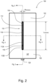
- FIG. 1 is a perspective view and FIG. 2 is a front view of an example wall-mounted load control device 100 (e.g., a dimmer switch).
- the load control device 100 may be used for controlling the power delivered from an alternating-current (AC) source to an electrical load (e.g., a lighting load).
- FIG. 3 is a right side cross-sectional view of the load control device 100 taken through the center of the load control device as shown in FIG. 2 .
- FIG. 4 is a top side cross-sectional view of the load control device 100 taken through the center of the load control device as shown in FIG. 2 .
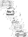
- FIG. 5 is a partial exploded view of the load control device 100 showing a faceplate 102 and an adapter plate 104 removed from the load control device.
- FIG. 6 is a rear perspective view of the faceplate 102.
- FIG. 7 is an exploded view of the load control device 100 showing a portion of an antenna of the load control device.
- the load control device 100 may include a touch sensitive actuator 110.
- the touch sensitive actuator may be horizontally oriented along a longitudinal axis of the load control device 100.
- the faceplate 102 may have a body portion 105.
- the body portion 105 may define a front surface 107 of the faceplate 102.
- the faceplate 102 may include a non-standard opening 106 in the front surface 107 of the body portion 105.
- the opening 106 may be adapted to receive the touch sensitive actuator 110, for example, when the faceplate 102 is installed on the load control device 100.
- the opening 106 may have a length L OPENING .
- the opening may have a width W OPENING .
- the opening 106 may have an aspect ratio (e.g., L OPENING : W OPENING ) of approximately 16:1.
- L OPENING may be approximately 2.83 inches and the width W OPENING may be approximately 0.17 inches.
- the body portion 105 of the faceplate 102 may be made from, for example, a non-conductive material, such as plastic.
- the body portion 105 of the faceplate 102 may be made from a conductive material, such as metal, for example.
- the body portion may be made of a non-conductive material and the front surface 107 may include a conductive material (e.g., a metallic material), for example as described herein.
- the touch sensitive actuator 110 may include an actuation member 112.
- the actuation member 112 may include first and second portions 112A, 112B.
- the load control device 100 may include a bezel 114.
- the bezel 114 may be shaped to form an opening 113.
- the actuation member 112 may extend through the opening 113 in the bezel 114 to contact a touch sensitive device 130 ( e.g., a resistive touch pad) inside the load control device 100.
- the touch sensitive device 130 may be referred to as a user interface that a user may interact with, for example, in order to control a lighting load.
- the load control device 100 may be operable to control the intensity of the controlled lighting load in response to actuations of the actuation member 112 and/or the touch sensitive device 130.
- the bezel 114 may include a break 116 that may separate the upper portion 112A and the lower portion 112B of the actuation member 112.
- the load control device 100 may be configured to toggle a connected lighting load from on to off and vice versa, for example, upon actuation of the lower portion 112B of the actuation member 112.
- the load control device 100 may be configured to adjust an intensity of the lighting load, for example, based on actuation(s) of the upper portion 112A of the actuation member 112.
- the load control device 100 may adjust the intensity of the lighting load to a particular level based on the position of the actuation along the length of the actuation member 112.
- the load control device 100 may include a yoke 120.
- the yoke 120 may be used to mount the load control device 100 to a standard electrical wallbox, for example, via mounting screws (not shown) that may be received through two mounting holes 122.
- the yoke 120 may be made from a conductive material.
- the faceplate 102 may be mounted ( e.g., snapped) to the adapter plate 104, for example, such that the bezel 114 is housed behind the faceplate 102 and the bezel 114 extends through the opening 106.
- tabs 108 on the top and bottom sides of the faceplate 102 may be adapted to snap to tabs 109 on the top and bottom edges of the adapter plate 104.
- the adapter plate 104 may connect to the yoke 120 of the load control device 100, for example, via faceplate screws (not shown) that may be received through openings 124 in the adapter plate 104 and corresponding openings 125 in the yoke 120.
- the load control device 100 may include an enclosure 126 ( e.g., a back box).
- the enclosure 126 may house a rear printed circuit board (PCB) 128.
- a portion of the electrical circuitry of the load control device 100 may be mounted on the rear PCB 128.
- An air-gap actuator 129 may allow for actuation of an internal air-gap switch (not shown) to electrically disconnect the electrical load from the AC power source, for example, by pulling the air-gap actuator down.
- the load control device 100 may include a non-conductive cradle 132.
- the cradle 132 may be shaped to form a recess 134.
- the recess 134 may be used to hold the touch sensitive device 130.
- the touch sensitive device 130 may be electrically coupled to a front printed circuit board (PCB) 136, for example, via connector pins 138 that may be received in through-holes 139 in the front PCB 136.
- the bezel 114 may attach to the yoke 120, for example, such that the cradle 132 and the front PCB 136 are positioned ( e.g., captured) between the bezel 114 and the yoke 120.
- the bezel 114 may attach to the cradle 132 via screws 140 (e.g., electrically conductive screws) that may be received through openings 141 in the bezel 114 and corresponding openings 142 in the yoke 120.
- the air-gap actuator 129 may be positioned between the cradle and the yoke 120 and is configured to actuate the internal air-gap switch inside of the enclosure 126 through a central opening 144 in the yoke 120.
- the air-gap switch actuator 129 may be configured to translate along the longitudinal axis of the load control device 100 to open and close the internal air-gap switch.
- the front PCB 136 may be connected to the rear PCB 128, for example, via two electrical connectors 145 that may extend through openings 147 in the cradle 132.
- the actuation member 112 may be positioned ( e.g., captured) between the bezel 114 and the touch sensitive device 130, for example, in the recess 134 of the cradle 132, such that the front surface of the actuation member 112 may extend through the opening 113 in the bezel 114.
- the actuation member 112 may include actuation posts 146 that may contact the front surface of the touch sensitive device 130.
- the posts 146 may be arranged in a linear array along the length of the actuation member ( e.g., along the longitudinal axis of the load control device 100).
- the actuation posts 146 may act as force concentrators to concentrate the force from an actuation of the front surface of the actuation member 112 to the touch sensitive device 130.
- the front PCB 136 may be shaped to form holes 148.
- the actuation posts 146 may extend through the holes 148 in the front PCB 136 to contact the touch sensitive device 130.
- An example of a load control device having a thin touch sensitive actuator is described in greater detail in commonly-assigned U.S. Patent No. 7,791,595, issued September 7, 2010 , entitled TOUCH SCREEN ASSEMBLY FOR A LIGHTING CONTROL, the entire disclosure of which is hereby incorporated by reference.
- the front PCB 136 may include visual indicators, for example, light-emitting diodes (LEDs) 149, that may be arranged in a linear array adjacent to a rear surface of the actuation member 112.
- the actuation member 112 may be substantially transparent, for example, such that the LEDs 149 are operable to illuminate portions of the front surface of the actuation member 112.
- Two different color LEDs 149 may be positioned behind the lower portion 112B of the actuator member 112. For example, the lower portion 112B may be illuminated with blue light when the lighting load is on and the lower portion 112B may be illuminated with orange light when the lighting load is off.
- the LEDs 149 behind the upper portion 112A of the actuation member 112 may be blue and may be illuminated, for example, as a bar graph to display the intensity of the lighting load when the lighting load is on.
- the operation of the LEDs 149 is described in greater detail in U.S. Patent No. 7,592,925, issued September 22, 2009 , entitled LIGHTING CONTROL HAVING AN IDLE STATE WITH WAKE-UP UPON ACTUATION, the entire disclosure of which is hereby incorporated by reference.
- the load control device 100 may include an antenna (e.g., a slot antenna).
- the antenna may comprise a driven element 150, and for example, may be said to include one or more other elements.
- the antenna may comprise any combination of the driven element 150, a conductive member (e.g., a conductive member 170), the yoke 120, one or more conductive elements ( e.g., a conductive faceplate and/or a conductive backer, as described herein), and/or the like.
- the antenna may include a wireless communication circuit 160.
- the driven element 150 may be coupled to the wireless communication circuit 160.
- the wireless communication circuit 160 may drive the driven element 150 of the antenna.
- the wireless communication circuit 160 may be used for transmitting and/or receiving radio-frequency (RF) signals, for example, via the antenna.
- the wireless communication circuit 160 may communicate RF signals at a communication frequency f RF ( e.g., approximately 434 MHz).
- f RF e.g., approximately 434 MHz
- the wireless communication circuit 160 may include an RF receiver, an RF transmitter, and/or an RF transceiver.
- the wireless communication circuit 160 may be mounted to the rear PCB 128 inside the enclosure 126.
- the driven element 150 may be formed of a conductive material (e.g., an electrically-conductive material).
- the driven element 150 may be substantially planar.
- the drive element 150 may be substantially planar except for feet 155, for example, as shown in Fig. 7 .
- the driven element 150 may be located between the bezel 114 and the front PCB 136.
- the drive element 150 may be adapted to be attached to a rear surface of the bezel 114.
- the drive element 150 may be printed or painted on the rear surface of the bezel 114.
- the driven element 150 may be a conductive label that is adheres to the rear surface of the bezel 114.
- the driven element 150 may include a main slot 152.
- the main slot 152 may extend along the longitudinal axis of the load control device 100.
- the main slot 152 may be approximately the same size as the opening 118 in the faceplate 102 through which the bezel 114 extends.
- the main slot 152 is aligned with the opening 118 of the faceplate 102.
- the actuation posts 146 of the actuation member 112 extend through the main slot 152 to the touch sensitive device 130.
- the driven element 150 may form openings 154.
- the screws 140 that attach the bezel 114 to the yoke 120 may extend through the openings 154, such that the screws 140 may not be electrically coupled to the driven element 150.
- the driven element 150 may include the feet 155 (e.g., drive points) that may be electrically connected to pads 156 on the front PCB 136 to allow for electrical connection to the wireless communication circuit 160 on the rear PCB 128 through the connectors 145.
- the feet 155 may be located on opposite sides of the main slot 152.
- the feet 155 may be located at approximately the middle of the main slot, as exemplified in FIG. 7 .
- the wireless communication circuit 160 may be configured to drive the feet 154 differentially, such that the driven element 150 operates as a slot antenna and radiates the RF signals.
- the driven element 150 may operate as a radiating element of the load control device 100.
- One or more elements of the antenna may act as a radiating element of the antenna.
- a radiating element may be any element that radiates a signal (e.g., a RF signal).
- a signal e.g., a RF signal
- one or more of the driven element 150, the conductive member (e.g. , a conductive member 170), the yoke 120, and/or one or more of the conductive elements (e.g. , the conductive faceplate and/or the conductive backer) may act as a radiating element of the antenna.
- One of the radiating elements may be referred to as an outer-most radiating element.
- the outer-most radiating element may be the structure that interfaces with the broadcasting medium (e.g., ambient air, for example, the air that is immediately surrounding the load control device 100).
- the driven element 150 and/or one of the conductive elements e.g., the conductive faceplate and/or the conductive backer
- the driven element 150 may operate as the outer-most radiating element of the load control device 100 when, for example, the faceplate 102 is not installed on the load control device 100 or a non-conductive ( e.g., 100% plastic) faceplate is installed on the load control device 100.
- the length and/or width of the main slot 152 of the driven element 150 may determine the inductance of the driven element 150.
- the resonant frequency of the antenna may be a function of the inductance of the driven elements 150.
- the resonant frequency of the antenna may be a function of the dimensions ( e.g., length and/or width) of the main slot 152.
- a communication range (e.g., a transmission range and/or reception range) of the antenna at the communication frequency f RF of the wireless communication circuit 160 may depend on the length and/or width of the main slot 152.
- the overall size of the driven element 150 and the dimension of the main slot 152 may be limited by the size of the mechanical structures of the load control device 100 ( e.g., the bezel 114).
- the driven element 150 may include wrap-around slot portions 158 to increase the inductance of the driven element 150.
- the wrap-around portions 158 may extend from the ends of the main slot 152.
- the wrap-around portions 158 may be oriented substantially parallel to the main slot 152.
- the length of the main slot 152 and the wrap-around slot portions 158 may depend upon the communication frequency f RF of the wireless communication circuit 160.
- the wrap-around slot portion 158 may be formed of other shapes, such as, for example, spiral shapes.
- the desired length of the main slot 152 to maximize the communication range of the antenna may be shorter. Accordingly, the driven element 150 may not include the wrap-around slot portions 158. The length of the main slot 152 may be shortened.
- the antenna of the load control device 100 may include a dual resonant structure having two resonant frequencies, such that the load control device 100 is able to communicate at two different communication frequencies (e.g., approximately 434 MHz and 868 MHz).
- the load control device 100 may be mounted to a metal and/or plastic wallbox.
- One or more components of the faceplate assembly e.g., the faceplate 102 and/or the adapter plate 104) may be made of a conductive material (e.g., a metal) and/or a non-conductive material ( e.g., plastic).
- the load control device 100 may be configured such that an impedance of the antenna, and the communication range (e.g., a transmission and/or reception range) of the antenna at the communication frequency f RF may be substantially consistent over various installation conditions.
- the antenna may cause an electric field to be generated, for example, when the antenna is transmitting. When the load control device 100 is installed in a metal wallbox, the electric field may cause current to flow through the metal wallbox and affect the communication range of the antenna at the communication frequency f RF .
- the load control device 100 may include a conductive member 170.
- the conductive member 170 may be a conductive label, such as a metal label.
- the conductive member 170 may wrap around the back of the enclosure 126 between points on opposite sides 121 of the yoke 120.
- the conductive member 170 may wrap around the back of the enclosure 126 between opposites sides of the central opening 143 and adjacent the feet 155 of the driven element 150.
- the conductive member 170 may extend horizontally around the back of the enclosure 126 at the center of the yoke 120.
- the conductive member 170 may be directly connected or capacitively coupled to the opposite sides 121 of the yoke 120.
- the conductive member 170 may be screwed to the yoke 120 via one or more conductive screws.
- the conductive member 170 may include a conductive coating, a conductive paint, a conductive label, and/or a conductive strap 172, for example, as illustrated in FIG. 8 .
- the strap 172 may be made of a conductive material, such as metal.
- the strap 172 may be strapped onto the load control device 100 around the back side of the enclosure 126 extending from both sides 121 of the yoke 120.
- the enclosure 126 may be a metalized enclosure made of a conductive material or infused with a conductive material.
- the conductive member 170 may be a part of the enclosure 126 and/or inside of the enclosure. For example, the conductive member 170 may be integrated into the enclosure 126.
- the yoke 120 may be approximately as wide as the enclosure 126, for example, to provide for capacitive coupling between the conductive member 170 and the yoke 120. If the load control device 100 is installed in a metal wallbox and the sides 121 of the yoke 120 ( e.g., near the center of the yoke 120 where the conductive member 170 is capacitively coupled to the yoke) become electrically shorted to the metal wallbox, the communication range of the antenna at the communication frequency f RF may be affected.
- the load control device 100 may include a non-conductive element (not shown) to prevent the sides 121 of the yoke 120 from contacting the metal wallbox.
- the non-conductive element e.g., electrical tape
- the non-conductive cradle 132 may have tabs (not shown) that extend out from the sides of the cradle 132 beyond the sides 121 of the yoke 120.
- the non-conductive cradle 132 may have flanges (not shown) that extend out from the sides of the cradle 132 and wrap around the sides 121 of the yoke 120.
- the non-conductive cradle 132 extend slightly beyond the sides 121 of the yoke 120 ( e.g., by approximately 0.040").
- the non-conductive cradle 132 may have one or more nubs (not shown) that are positioned in cut-outs (not shown) in the yoke 120, such that the nubs extend into the plane of the yoke 120 and extend beyond the sides 121 of the yoke 120.
- the load control device 100 may comprise one or more conductive elements.
- the load control device may comprise a conductive faceplate (e.g., a conductive faceplate 180, a conductive faceplate 220, and/or the like) and/or a conductive backer ( e.g., a conductive backer 210, a conductive backer 230, and/or the like).
- the conductive elements may be partially or entirely made of a conductive material (e.g., a metallic material).
- the conductive elements may be capacitively coupled and/or electrically coupled to the driven element 150.
- FIG. 9 is a rear perspective view and FIG. 10A is a front view of an example conductive faceplate 180.
- FIG. 10B is a front view of the driven element 150 of the antenna and
- FIG. 10C is a front view of the conductive faceplate 180 and the driven element 150 overlaid on top of each other.
- FIG. 11 is a partial right side cross-sectional view of the conductive faceplate 180.
- FIG. 12 is an enlarged perspective view of a conductive spring element 190 of the conductive faceplate 180.
- FIG. 13 is an enlarged partial top cross-section view of the load control device 100 with the conductive faceplate 180 installed.
- the conductive faceplate 180 may include a conductive material 182, which for example, may be arranged over a plastic carrier 184.
- the conductive material 182 may be, for example, a conductive sheet, a conductive paint, a conducive label, and/or the like.
- the plastic carrier 184 may be approximately the same size and shape as the plastic faceplate 102.
- the conductive faceplate 180 may form an opening 186 through which the bezel 114 of the load control device 100 may extend when the conductive faceplate 180 is installed on the load control device 100.
- the conductive material 182 may be substantially planar.
- the conductive material 182 may be substantially planar except for outer portions that may wrap around the edges of the faceplate 180, for example, as illustrated in Fig. 9 .
- the conductive material 182 may be made from one or more metallic materials.
- the conductive material 182 may have one or more finishes.
- Example finishes for the conductive material 182 include satin nickel, antique brass, bright chrome, stainless steel, gold, clear anodized aluminum, etc.
- the plastic carrier 184 may include tabs 188 adapted to snap to tabs 109 on the top and bottom edges of the adapter 104. Similar to the plastic faceplate 102, the opening 186 of the conductive faceplate 180 may have a length L OPENING of approximately 2.83 inches and a width W OPENING of approximately 0.17 inches.
- the conductive faceplate 180 may have metallization on approximately 96% of the front surface.
- the aspect ratio of the conductive faceplate 180 may range from approximately 3:1 to 20:1, and/or the conductive faceplate 180 may have metallization on greater than or equal to approximately 85% of the front surface.
- the conductive faceplate 180 may be made entirely of metal.
- the conductive faceplate 180 may not include the plastic carrier 184.
- the conductive material 182 may be integrated into the conductive faceplate 180, for example, internal to the plastic carrier 184.
- the conductive material 182 may operate as a radiating element of the antenna.
- the conductive material 182 may operate as the outer-most radiating element of the antenna when the conductive faceplate 180 is installed on the load control device 100.
- the conductive faceplate 180 may have a conductive surface ( e.g., the conductive material 182).
- the conductive surface of the conductive faceplate 180 may provide a radiating structure for the radio-frequency signals transmitted from and/or received by the load control device 100 ( e.g., via the ambient air).
- the conductive material 182 may be located in a plane that is substantially parallel to a plane of the driven element 150 of the antenna.
- the conductive material 182 may be offset from the driven element 150 by a distance D OFFSET-METAL (e.g. , approximately 0.113 inches) as shown in FIG. 13 , such that the conductive material 182 is capacitively coupled to the driven element 150.
- D OFFSET-METAL e.g. , approximately 0.113 inches
- the geometry and/or dimensions of the opening 186 of the conductive faceplate 180 may be a part of the radiating element of the antenna.
- the conductive material 182 may be electrically coupled directly to the driven element 150 and/or the wireless communication circuit 160.
- the conductive material 182 may be electrically coupled to the yoke 120 at one point ( e.g., to operate as a patch antenna).
- the load control device 100 may include a hybrid slot-patch antenna when the conductive faceplate 180 is installed on the load control device 100.
- the hybrid slot-patch antenna may be referred to as a slatch antenna.
- the conductive spring element 190 may operate to electrically couple the conductive material 182 to the yoke 120 through the screws 140 that attach the bezel 114 to the yoke 120.
- the conductive spring element 190 may be bent at a joint 192.
- the conductive spring element 190 may include two legs 194 that extend down to respective feet 196.
- the conductive spring element 190 may be received through an opening 198 in the plastic carrier 184, such that the feet 196 are captured between the conductive material 182 and the plastic carrier 184, and the feet 196 contact a back side 199 of the conductive material 182.
- the joint 192 contacts one of the screws 140 and the conductive spring element 190 is compressed between the screw and the metallic plate 182.
- the conductive spring element 190 electrically couples together the metallic plate 182 and the yoke 120 via one of the screws 140 that extends through one of the openings 154 in the driven element 150 as shown in FIG. 10C .
- FIG. 14 is a simplified equivalent schematic diagram of the antenna of the load control device 100 when no faceplate and/or a plastic faceplate (e.g., a 100% plastic faceplate, such as the plastic faceplate 102) is installed on the load control device 100.
- FIG. 15 is a simplified equivalent schematic diagram of the antenna of the load control device 100 when a conductive faceplate ( e.g., the conductive faceplate 180) is installed on the load control device 100.
- the wireless communication circuit 160 may be located inside the enclosure 126.
- the conductive member 170 may wrap around the enclosure 126 extending between the sides of the yoke 120. As described herein, the conductive member 170 may include conductive paint, label, and/or strap 172.
- the main slot 152 of the driven element 150 may be characterized by an inductance L SLOT1 .
- the wireless communication circuit 160 is coupled to the driven element 150 via two capacitors C 1 , C 2 , which are located on ( e.g., mounted to) the front PCB 136.
- Each of the capacitors C 1 , C 2 may have a capacitance of, for example, approximately 2.2 pF.
- a capacitor C 3 (e.g., having a capacitance of approximately 4.3 pF) may be mounted to the front PCB 136.
- the capacitor C 3 may be electrically coupled between the drive points ( e.g., the legs 155) of the driven element 150.
- Each side of the driven element 150 may be capacitively coupled through respective capacitances C A1 , C A2 to the touch sensitive device 130, which may be characterized by a resistance R A .
- Each side of the driven element 150 may be capacitively coupled to a common mode point.
- the common mode point may include the electrical traces coupled to the LEDs 149 on the front PCB 136.
- a first side of the main slot 152 of the driven element 150 may be coupled to the common mode point via the parallel combination of a capacitance C B1 and a resistance R B1 .
- a second side of the main slot 152 of the driven element 150 may be coupled to the common mode point via the parallel combination of a capacitance C B2 and a resistance R B2 .
- the yoke 120 may be coupled to the common mode point via a high impedance path that may include the series combination of a capacitance C C1 and a resistance Rci.
- the sides of the driven element 150 may be capacitively coupled to the conductive material 182 via respective capacitances C D1 , C D2 .
- Capacitances C D1 , C D2 may have values that are dependent upon the distance D OFFSET-METAL between the driven element 150 and the conductive material182.
- the sides of the main slot 152 of the driven element 150 may be capacitively coupled together via a capacitance C D3 .
- Capacitance C D3 may have a value that may depend upon the dimensions of the wrap-around slot portions 158 of the driven element 150.
- the value of capacitance C D3 may depend on the amount of the main slot 152 of the driven element 150 that does not overlap the opening 186 in the conductive material 182.
- the conductive material 182 may be directly electrically coupled to the driven element 150 and/or wireless communication circuit 160, e.g., via two drive points located on opposite sides of the elongated opening at approximately the middle of the elongated opening.
- the opening 186 in the conductive material 182 of the conductive faceplate 180 may be characterized by an inductance L SLOT2 .
- the sides of the opening 186 in the conductive material 182 may be capacitively coupled to the common mode point through a first parallel combination of a capacitance C E1 and a resistance R E1 , and a second parallel combination of a capacitance C E2 and a resistance R E2 , respectively.
- the sides of the opening 186 of the conductive material 182 may be coupled to the yoke 120 via respective high impedance paths including a first series combination of a capacitance C F1 and a resistance R F1 , and a second series combination of a capacitance C F2 and a resistance R F2 , respectively.
- the conductive material 182 may be coupled to the yoke 120 through a low impedance path (e.g., through the conductive spring element 190 and one of the screws 140), an example of which is represented by the parallel combination of a capacitance C G1 and a resistance R G1 in FIG. 15 .
- FIG. 16 is a perspective view of an example multi-gang load control device installation 200 (e.g., a multi-gang control system).
- a multi-gang installation is shown in FIG. 16 .
- the multi-gang installation 200 includes three load control devices installed in a multi-gang electrical wallbox (e.g., a three-gang wallbox).
- each of the load control devices in the multi-gang installation 200 may be the same as the load control device 100 described above.
- the multi-gang installation 200 may include a multi-gang faceplate 202.
- the multi-gang face plate 202 may have a front surface 204 and three elongated openings 206A, 206B, 206C for receiving respective touch sensitive actuators 110A, 110B, 110C of the load control devices.
- the multi-gang faceplate 202 may be a conductive multi-gage faceplate (e.g., a metal multi-gang faceplate) and the front surface 204 may include a conductive material (e.g., similar to the single-gang conductive faceplate 180).
- the conductive material may be made from one or more metallic materials.
- the conductive material may be substantially planar.
- the load control devices may each include an antenna having a respective driven element 150A, 150B, 150C.
- FIG. 17 is a front view of the multi-gang conductive faceplate 202 overlaid overtop of the driven elements 150A, 150B, 150C.
- the multi-gang conductive faceplate 202 may include three conductive spring elements 208A, 208B, 208C ( e.g., each similar to the conductive spring element 190 shown in FIG. 11 and 12 ).
- the conductive spring elements 208A, 208B, 208C may each contact one of the screws 140 on the respective load control devices, such that the yoke 120 of each of the load control devices is electrically coupled to the conductive material of the front surface 204 of the multi-gang conductive faceplate 202.
- the conductive spring elements 208A, 208B, 208C may be configured to extend through respective openings 154A, 154B, 154C of the driven elements 150A, 150B, 150C to contact the respective screws 140. As shown in FIG. 17 , the conductive spring elements 208A, 208B, 208C extend through the same opening 154A, 154B, 154C on each of the respective load control devices ( e.g., the top left opening).
- FIG. 18 is a front view of another example multi-gang conductive faceplate 202' and the driven elements 150A, 150B, 150C overlaid overtop of each other.
- the multi-gang conductive faceplate 202' may include conductive spring elements 208B' located near the bottom end of the middle opening 206B.
- the outer conductive spring elements 208A, 208C extend through the top left opening 154A, 154C of the respective driven elements 150A, 105C.
- the conductive spring element 208B' extends through an opening (e.g., a lower left opening 154B') of the middle driven element 150B that is relatively different from the openings that conductive spring elements 208A, 208C extend. Accordingly, the locations at which the driven elements 150A, 150B, 150C are coupled to the conductive material of the front surface 204 of the multi-gang conductive faceplate 202 may be dependent upon the communication frequency f RF of the load control devices.
- the impedance of the antenna of a load control device may be different based on whether the plastic faceplate 102, the conductive faceplate 180, or no faceplate is installed on the load control device.
- the communication frequency f RF of the wireless communication circuit 160 may be selected and/or the structure of the load control device may be designed, such that the communication range of the load control device at the communication frequency f RF is acceptable independent of whether the plastic faceplate 102, or the conductive faceplate 180 is installed.
- the communication range may be acceptable, for example, when the load control device is able to successfully receive and/or transmit RF signals.
- the load control device 100 may be characterized by a first communication range R 1 at the communication frequency f RF when the plastic faceplate 102, or no faceplate is installed.
- the load control device may be characterized by a second communication range R 2 when the conductive faceplate 180 is installed.
- the second communication range R 2 may be greater than the first communication range R 1 .
- the first communication range R 1 may be greater than or equal to a minimum acceptable communication range R MIN (e.g. , approximately 30 feet), such that the load control device is able to properly transmit and receive the RF signals when the plastic faceplate 102, or no faceplate is installed.
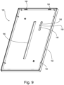
- a faceplate (e.g., the plastic faceplate 102) may include a conductive backer 210.
- the conductive backer 210 may operate to bring the impedance of the antenna when the plastic faceplate 102 is installed closer to the impedance of the antenna when the conductive faceplate 180 is installed.
- the conductive backer 210 may comprise a conductive material, such as, for example, a metallic sheet and/or the like.
- the conductive backer 210 may be made from one or more metallic materials.
- FIG. 19 is a rear perspective view of a plastic faceplate 102 having the conductive backer 210 attached to a rear surface 212 of the faceplate 102.
- FIG. 20 is a partial exploded view of the load control device 100illustrating the plastic faceplate 102, where the adapter plate 104 has been removed from the load control device 100 and the conductive backer 210 has been removed from the plastic faceplate 102.
- FIG. 21 is a right side cross-sectional view of the load control device 100 taken through the center of the load control device 100 ( e.g., as shown in FIG. 2 ) with the conductive backer 210 attached to the plastic faceplate 102.
- FIG. 22 is a top side cross-sectional view and FIG.
- FIG. 23 is an enlarged partial top side cross-sectional view of the load control device 100 taken through the center of the load control device ( e.g., as shown in FIG. 2 ) with the conductive backer 210 attached to the plastic faceplate 102.
- FIG. 24A is a front view of the conductive backer 210
- FIG. 24B is a front view of the driven element 150 of the antenna of the load control device 100.
- FIG. 24C is a front view of the plastic faceplate 102, the conductive backer 210, and the driven element 150 overlaid overtop of each other.
- the conductive backer 210 may mimic the structure of the conductive material 182.
- the conductive backer 210 may operate as the radiating element of the antenna.
- the conductive backer 210 may operate as the outer-most radiating element of the antenna if the plastic faceplate 102 having the conductive backer 210 is installed on the load control device 100.
- the conductive backer 210 may act as a radiating element and as a capacitive coupling member when the conductive faceplate 180 is installed on the load control device 100, and in such instances, the conductive faceplate 180 ( e.g., the conductive material 182) may act as the outer-most radiating element of the antenna.
- the conductive backer 210 may capacitively couple the conductive faceplate 180 to the driven element 150.
- the conductive backer 210 may be located in a plane that is substantially parallel to a plane of the driven element 150 of the antenna, for example, as with the conductive material 182.
- the conductive backer 210 may be offset from the driven element 150 by a distance D OFFSET-PLASTIC ( e.g ., approximately 0.050 inches), for example as shown in FIG. 23 .
- the conductive backer 210 may be directly connected or capacitively coupled to the opposite sides 121 of the yoke 120.
- the conductive elements 210 may be capacitively coupled to the driven element 150.
- the conductive backer 210 may include a central slot 214 that extends along the longitudinal axis of the load control device 100.
- the central slot 214 may be approximately the same size as the opening 106 in the plastic faceplate 102.
- the conductive backer 210 may be electrically coupled to the yoke 120 at one point, such that the antenna may operate as a patch antenna (e.g., a hybrid slot-patch, or slatch antenna).
- the conductive backer 210 may include a contact member 216.
- the contact member 216 may be formed as part of the conductive backer 210.
- the contact member 216 may be elongated.
- the contact member 216 may be biased towards the load control device 100.
- the contact member 216 may contact one of the screws 140 that attaches the bezel 114 to the yoke 120 to electrically couple the conductive backer 210 to the yoke 120.
- the contact member 216 may be wider at the base where the contact member 216 meets the conductive backer 210 ( e.g., as shown in Figs. 26-27C ).
- the contact member 216 may be of any shape, size, or structure to provide electrical connection between the conductive backer 210 and one of the screws 140.
- the conductive backer 210 may include wrap-around slot portions 218. The dimensions of the wrap-around slot portions 218 may be adjusted to change the impedance of the antenna, as described herein.
- the conductive backer 210 may be formed as a part of the plastic faceplate 102, e.g., integrated onto a back surface of the plastic faceplate 102 or internal to the plastic faceplate 102.
- the conductive backer 210 may be attached to the adapter plate 104 ( e.g., the front or rear surface of the adapter plate).
- the conductive element 210 may be electrically coupled to the yoke 120 via one of two conductive faceplate screws received through the openings 124 in the adapter and the openings 125 in the yoke 120.
- FIG. 25 is a simplified equivalent schematic diagram of the antenna of the load control device 100 when the plastic faceplate 102 with the conductive backer 210 is installed on the load control device.
- the central slot 214 of the conductive backer 210 may be characterized by an inductance L SLOT3 .
- the conductive backer 210 may be coupled to the yoke 120 through a low impedance path ( e.g., through the contact member 216 and one of the screws 140), an example of which is represented by the series combination of an inductance L H1 and a resistance R H1 in FIG. 25 .
- a distance D OFFSET-PLASTIC may refer to a distance between the driven element 150 and the conductive backer 210 on the plastic faceplate 102.
- a distance D OFFSET-METAL may refer to a distance between the driven element 150 and the metallic plate 182 of the conductive faceplate 180.
- the distance D OFFSET-PLASTIC may be smaller than the distance D OFFSET-METAL .
- the values of the capacitances C D1 , C D2 of the capacitive coupling between the conductive backer 210 and the driven element 150 may be larger, for example, because the distance D OFFSET-PLASTIC may be smaller than the distance D OFFSET-METAL .
- the value of the capacitance C D3 between the sides of the main slot 152 of the driven element 150 may depend on the size of the wrap-around slot portions 218 of the conductive backer 210, for example, as compared to the size of the wrap-around slot portions 158 of the driven element 150. As the amount of overlap of the wrap-around slot portions 218 of the conductive backer 210 and the wrap-around slot portions 158 of the drive element increases, the value of the capacitance C D3 between the sides of the main slot 152 of the driven element 150 may decrease, and vice versa.
- the dimensions (e.g., the lengths) of the wrap-around slot portions 218 of the conductive backer 210 may be adjusted to change the value of the capacitance C D3 .
- the value of the capacitance C D3 may be changed to bring the impedance of the antenna with the plastic faceplate 102 having the conductive backer 210 being installed closer to the impedance of the antenna when the conductive faceplate 180 is installed.
- the lengths of the wrap-around slot portions 218 of the conductive backer 210 may be increased and/or the widths of the wrap-around slot portions 218 may be increased to change the value of the capacitance C D3 .
- Increasing the lengths of the wrap-around slot portions 218 and/or the widths of the wrap-around slot portions 218 may bring the impedance of the antenna when the plastic faceplate 102 having the conductive backer 210 is installed closer to the impedance of the antenna when the conductive faceplate 180 is installed.
- the conductive backer 210 may provide a capacitive loading on the antenna that is approximately equal to the capacitive loading provided by the conductive faceplate 180 that has an equivalent size and shape as the plastic faceplate 102.
- a conductive backer 210 may be mounted to a rear surface of the plastic carrier 184 of the conductive faceplate 180 ( e.g., as shown in FIG. 9 ).
- FIG. 26 is a rear perspective view
- FIG. 27A is a front view of an example conductive faceplate 220 having a conductive backer 230.
- FIG. 27B is a front view of the driven element 150 of the antenna
- FIG. 27C is a front view of the conductive faceplate 220, the conductive backer 230, and the driven element 150 overlaid overtop of each other.
- the conductive faceplate 220 may include a conductive material 222 arranged over a plastic carrier 224.
- the conductive material 222 may be, for example, a conductive sheet, a conductive paint, a conductive label, and/or the like.
- the conductive faceplate 220 may form an opening 226 through which the bezel 114 of the load control device 100 may extend when the conductive faceplate 220 is installed on the load control device 100.
- the plastic carrier 224 and the opening 226 of the conductive faceplate 222 may be approximately the same size and shape as the plastic carrier 184 and the opening 186, respectively, of the conductive faceplate 180 shown in FIG. 9 .
- the conductive material 222 may be substantially planar.
- the conductive material 222 may be substantially planar except for the portions that wrap around the edges of the faceplate 220, for example, as shown in FIG. 26 .
- the conductive material 222 may be made from one or more conductive, metallic materials.
- the conductive material 222 may one or more finishes.
- Example finishes include satin nickel, antique brass, bright chrome, stainless steel, gold, clear anodized aluminum, etc.
- the plastic carrier 224 may include tabs 228.
- the tabs 228 may be adapted to snap to tabs 109 on the top and bottom edges of the adapter 104.
- the conductive faceplate 220 may have metallization on approximately 96% of the front surface.
- the aspect ratio of the conductive faceplate 220 may range from approximately 3:1 to 20:1, and/or the conductive faceplate 220 may have metallization on greater than or equal to approximately 85% of the front surface.
- the conductive faceplate 220 may be made entirely of metal.
- the conductive faceplate 220 may not include the plastic carrier 224.
- the conductive material 222 may be integrated into the conductive faceplate 220, for example, internal to the plastic carrier 224.
- the conductive backer 230 may include a conductive material, such as, for example, a metallic sheet, a conductive label, a conductive paint, and/or the like.
- the conductive backer 230 may be attached to a rear surface 232 of the plastic carrier 224 of the conductive faceplate 220.
- the conductive backer 230 may be offset from the driven element 150 by a distance D OFFSET-BACKER (e.g. , similar to the distance D OFFSET-PLASTIC , such as approximately 0.050 inches).
- the conductive backer 230 may include a central slot 234 that extends along the longitudinal axis of the load control device 100.
- the central slot 234 may be approximately the same size as the opening 226 in the plastic carrier 224.
- the conductive material 222 and the conductive backer 230 may be located in respective planes that are substantially parallel to the plane of the driven element 150 of the antenna.
- the conductive material 222 of the conductive faceplate 220 may act as the outer-most radiating element of the antenna, for example, when the conductive faceplate 220 is installed on the load control device 100.
- the conductive backer 230 may act as the outer-most radiating element of the antenna, for example, when the conductive faceplate 220 is not installed on the load control device 100. If the conductive faceplate 220 is installed on the load control device 100, then the conductive backer 230 may act as a radiating element and the conductive material 222 may act as the outer-most radiating element of the antenna.
- the conductive backer 230 may be electrically coupled to the yoke 120 at one point, such that the antenna also operates as a patch antenna (e.g., a hybrid slot-patch, or slatch antenna).
- the conductive backer 230 may include a contact member 236.
- the contact member 236 may be formed as part of the conductive backer 230.
- the contact member 236 may be biased towards the load control device 100.
- the contact member 236 may be triangularly-shaped and may be wider at the base than the contact member 216 of the conductive backer 210, for example, as shown in FIG. 19 .
- the contact member 236 may contact one of the screws 140 that attaches the bezel 114 to the yoke 120 to thus electrically couple the conductive backer 230 to the yoke 120.
- the contact member 216 may be narrower than the contact member 236, for example, as shown in FIG. 19 and 26 .
- the contact member 236 may be of any shape, size, or structure to provide electrical connection between the conductive backer 230 and one of the screws 140.
- the conductive backer 230 may provide consistency in the RF communication range of the load control device at the communication frequency f RF independent of the type of metallic material, or finish of the conductive material 222.
- the conductive backer 230 may provide for consistency with the electrical connection between the conductive backer 230 and the yoke 120 independent of the type of metallic material or finish of the conductive material 222.
- the conductive backer 230 may include wrap-around slot portions 238.
- the wrap-around slot portions 238 may have dimensions that may be adjusted to change the impedance of the antenna.
- the slot portions 238 of the conductive backer 230 mounted to the conductive faceplate 220 may be sized and shaped to bring the impedance of the antenna when the conductive faceplate 220 with the conductive backer 230 is installed closer to the impedance of the antenna when the plastic faceplate 102 with the conductive backer 210 is installed.
- the slot portions 238 of the conductive backer 230 mounted to the conductive faceplate 220 may be longer than the slot portions 218 of the conductive backer 210 mounted to the plastic faceplate 102 that are shown in FIG. 19 .
- the slot portions 238 of the conductive backer 230 mounted to the conductive faceplate 220 may be sized and shaped, for example, to match the size and shape of the main slot 152 of the driven element 150 ( e.g., as shown in FIG. 27C ).
- a width W CE of the conductive backer 230 of the conductive faceplate 220 may be adjusted ( e.g., trimmed) to bring the impedance of the antenna when the conductive faceplate 220 with the conductive backer 230 is installed closer to the impedance of the antenna when the plastic faceplate 102 with the conductive backer 210 is installed.
- FIG. 28 is a simplified equivalent schematic diagram of the antenna of the load control device 100 when the conductive faceplate 220 is installed on the load control device 100.
- the conductive backer 230 of the conductive faceplate 220 may be coupled to the yoke 120 through a low impedance path ( e.g., through the contact member 236 and one of the screws 140), an example of which is represented by the series combination of an inductance L J1 and a resistance R J1 in FIG. 28 .
- the opening 226 in the conductive material 222 of the conductive faceplate 220 may be characterized by the inductance L SLOT2 .
- the conductive backer 230 may be capacitively coupled to conductive material 222 on each side of the opening 226 via respective capacitances C K1 , C K2 .
- the combination of the conductive material 222 and the conductive backer 230 of the conductive faceplate 220 may provide a capacitive loading on the antenna that is approximately equal to the capacitive loading provided by the plastic faceplate 102 with the conductive backer 210.
- FIG. 29 is a perspective view of an example wireless control device 250, e.g., a keypad device.
- the wireless control device 250 may include a faceplate 252 having an opening 254 for receiving a plurality of buttons 256.
- the faceplate 252 may be adapted to connect to an adapter plate 258 ( e.g., in a similar manner as the faceplate 102 connects to the adapter plate 104).
- the wireless control device 250 may be configured to transmit RF signals in response to actuations of the buttons 256.
- the faceplate 252 may include a conductive faceplate.
- the faceplate 252 may include a conductive material arranged over a plastic carrier ( e.g., such as the conductive faceplate 180).
- the buttons 256 may be made of a non-conductive material, such as plastic or glass.
- the wireless control device 250 may include an antenna having a driven element that is capacitively coupled to the conductive material of the faceplate 252, such that the conductive material operates as a radiating element of the antenna.
- the conductive material of the faceplate 252 may be directly electrically coupled to a yoke of the wireless control device 250 at a single electrical connection.
- the buttons 256 may be made of a conductive material, for example, a metallic sheet attached to a plastic carrier.
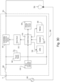
- FIG. 30 is a simplified block diagram of an example load control device 300 that may be deployed as, for example, the load control device 100 shown in FIG. 1-28 .
- the load control device 300 may include a hot terminal H that may be adapted to be coupled to an AC power source 302.
- the load control device 300 may include a dimmed hot terminal DH that may be adapted to be coupled to an electrical load, such as a lighting load 304.
- the load control device 300 may include a controllably conductive device 310 coupled in series electrical connection between the AC power source 302 and the lighting load 304.
- the controllably conductive device 310 may control the power delivered to the lighting load.
- the controllably conductive device 310 may include a suitable type of bidirectional semiconductor switch, such as, for example, a triac, a field-effect transistor (FET) in a rectifier bridge, two FETs in anti-series connection, or one or more insulated-gate bipolar junction transistors (IGBTs).
- An air-gap switch 329 may be coupled in series with the controllably conductive device 310.
- the air-gap switch 329 may be opened and closed in response to actuations of an air-gap actuator (e.g., the air-gap switch actuator 129).
- an air-gap actuator e.g., the air-gap switch actuator 129.
- the load control device 300 may include a control circuit 314.
- the control circuit 314 may include one or more of a processor (e.g., a microprocessor), a microcontroller, a programmable logic device (PLD), a field programmable gate array (FPGA), an application specific integrated circuit (ASIC), or any suitable controller or processing device.
- the control circuit 314 may be operatively coupled to a control input of the controllably conductive device 310, for example, via a gate drive circuit 312.
- the control circuit 314 may be used for rendering the controllably conductive device 310 conductive or non-conductive, for example, to control the amount of power delivered to the lighting load 304.
- the control circuit 314 may receive inputs from a touch sensitive actuator 316 (e.g., the touch sensitive actuator 110).
- the control circuit 314 may individually control LEDs 318 (e.g., the LEDs 149) to illuminate a linear array of visual indicators on the touch sensitive actuator.
- the control circuit 314 may receive a control signal representative of the zero-crossing points of the AC main line voltage of the AC power source 302 from a zero-crossing detector 319.
- the control circuit 314 may be operable to render the controllably conductive device 310 conductive and/or non-conductive at predetermined times relative to the zero-crossing points of the AC waveform using a phase-control dimming technique. Examples of dimmers are described in greater detail in commonly-assigned U.S. Patent No. 7,242,150, issued July 10, 2007 , entitled DIMMER HAVING A POWER SUPPLY MONITORING CIRCUIT; U.S. Patent No.
- the load control device 300 may include a memory 320.
- the memory 320 may be communicatively coupled to the control circuit 314 for the storage and/or retrieval of, for example, operational settings, such as, lighting presets and associated preset light intensities.
- the memory 320 may be implemented as an external integrated circuit (IC) or as an internal circuit of the control circuit 314.
- the load control device 300 may include a power supply 322.
- the power supply 322 may generate a direct-current (DC) supply voltage Vcc for powering the control circuit 314 and the other low-voltage circuitry of the load control device 300.
- the power supply 322 may be coupled in parallel with the controllably conductive device 310.
- the power supply 322 may be operable to conduct a charging current through the lighting load 304 to generate the DC supply voltage Vcc.
- the load control device 300 may include a wireless communication circuit 324 (e.g., the wireless communication circuit 160).
- the wireless communication circuit 324 may include a RF transceiver coupled to an antenna for transmitting and/or receiving RF signals.
- the antenna may include the slot or slatch antenna of the load control device 100 shown in FIG. 1-28 .
- the control circuit 314 may be coupled to the wireless communication circuit 324 for transmitting and/or receiving digital messages via the RF signals.
- the control circuit 314 may be operable to control the controllably conductive device 310 to adjust the intensity of the lighting load 304 in response to the digital messages received via the RF signals.
- the control circuit 314 may transmit feedback information regarding the amount of power being delivered to the lighting load 304 via the digital messages included in the RF signals.
- the control circuit 314 may be configured to transmit RF signals while the touch sensitive actuator 316 is being actuated, since the communication range of the antenna may be temporarily increased while a user's finger is adjacent the main slot 152 of the driven element 150.
- the wireless communication circuit 324 may include an RF transmitter for transmitting RF signals, an RF receiver for receiving RF signals, or an infrared (IR) transmitter and/or receiver for transmitting and/or receiving IR signals.
- IR infrared
- FIG. 31 is a simple diagram of an example load control system 400 (e.g., a lighting control system) in which a wall-mounted load control device 410 having a thin touch sensitive actuator (e.g., the load control device 100 and/or the load control device 300) may be deployed.
- the wall-mounted load control device 410 may be coupled in series electrical connection between an AC power source 402 and a first lighting load, e.g., a first light bulb 412 installed in a ceiling mounted downlight fixture 414.
- the first light bulb 412 may be installed in a wall-mounted lighting fixture or other lighting fixture mounted to another surface.
- the wall-mounted load control device 410 may be adapted to be wall-mounted in a standard electrical wallbox.
- the load control system 400 may include another load control device, e.g., a plug-in load control device 420.
- the plug-in load control device 420 may be coupled in series electrical connection between the AC power source 402 and a second lighting load, e.g., a second light bulb 422 installed in a lamp ( e.g., a table lamp 424).
- the plug-in load control device 420 may be plugged into an electrical receptacle 426 that is powered by the AC power source 402.
- the table lamp 424 may be plugged into the plug-in load control device 420.
- the second light bulb 422 may be installed in a table lamp or other lamp that may be plugged into the plug-in load control device 420.
- the plug-in load control device 420 may be implemented as a table-top load control device, or a remotely-mounted load control device.
- the wall-mounted load control device 410 may include a touch sensitive actuator 416 (e.g., the touch sensitive actuator 110 of the load control device 100 or the touch sensitive actuator 316 of the load control device 300) for controlling the light bulb 412.
- the wall-mounted load control device 410 may be configured to turn the light bulb 412 on and off, and to increase or decrease the amount of power delivered to the light bulb.
- the wall-mounted load control device 410 may vary the intensity of the light bulb by varying the amount of power delivered to the light bulb.
- the wall-mounted load control device 410 may increase or decrease the intensity of the light bulb from a minimum intensity (e.g ., approximately 1%) to a maximum intensity ( e.g., approximately 100%).
- the wall-mounted load control device 410 may be configured to provide visual indicators.
- the visual indicators may be arranged in a linear array on the touch sensitive actuator 416.
- the wall-mounted load control device 410 may be configured to illuminate the visual indicators to provide feedback of the intensity of the light bulb 412. Examples of wall-mounted dimmer switches are described in greater detail in U.S. Patent No. 5,248,919, issued September 29, 1993 , entitled LIGHTING CONTROL DEVICE, and U.S. Patent Application No. 13/780,514, filed February 28, 2013 , entitled WIRELESS LOAD CONTROL DEVICE.
- the load control system 400 may include a daylight control device, e.g., a motorized window treatment 430, mounted in front of a window for controlling the amount of daylight entering the space in which the load control system 400 is installed.
- the motorized window treatment 430 may include, for example, a cellular shade, a roller shade, a drapery, a Roman shade, a Venetian blind, a Persian blind, a pleated blind, a tensioned roller shade systems, or other suitable motorized window covering.
- the motorized window treatment 430 may include a motor drive unit 432 for adjusting the position of a covering material 434 of the motorized window treatment (e.g., a cellular shade fabric as shown in FIG. 1 ) in order to control the amount of daylight entering the space.
- the motor drive unit 432 of the motorized window treatment 430 may have an RF receiver and an antenna mounted on or extending from a motor drive unit of the motorized window treatment.
- the motor drive unit 432 of the motorized window treatment 430 may be battery-powered or may receive power from an external direct-current (DC) power supply. Examples of battery-powered motorized window treatments are described in greater detail in commonly-assigned U.S. Patent Application Publication No. 2012/0261078, published October 18, 2012 , entitled MOTORIZED WINDOW TREATMENT, and U.S. Patent Application No. 13/798,946, filed March 13, 2013 , entitled BATTERY-POWERED ROLLER SHADE SYSTEM.
- the load control system 400 may include one or more input devices, e.g. , RF transmitters, such as a wall-mounted remote control device 440, a battery-powered handheld remote control device 450, an occupancy sensor 460, or a daylight sensor 470.
- RF transmitters such as a wall-mounted remote control device 440, a battery-powered handheld remote control device 450, an occupancy sensor 460, or a daylight sensor 470.
- the wall-mounted load control device 410 and/or the plug-in load control device 420 may be configured to receive digital messages via wireless signals, e.g. , radio-frequency (RF) signals 406.
- the wireless signals may be transmitted by the wall-mounted remote control device 440, the battery-powered remote control device 450, the occupancy sensor 460, or the daylight sensor 470.
- the wall-mounted load control device 410 and/or the plug-in load control device 420 may be configured to turn the respective light bulb 412, 422 on and off, and to increase or decrease the intensity of the respective light bulb.
- the wall-mounted load control device 410 and/or the plug-in load control device 420 may be implemented as electronic switches configured to turn on and off ( e.g., only turn on and off) the respective light bulbs 412, 422.
- the wall-mounted remote control device 440 may include a thin touch sensitive actuator 442 (e.g., similar to the touch sensitive actuator 416 of the wall-mounted load control device 410).
- the wall-mounted remote control device 440 may not include an internal load control circuit.
- the wall-mounted remote control device 440 may not directly be connected to an electrical load.
- the wall-mounted remote control device 440 may transmit RF signals 406 in response to actuations of the touch sensitive actuator 442.
- the RF signals 406 may be transmitted at a communication frequency f RF ( e.g., approximately 434 MHz) using a proprietary RF protocol, such as the ClearConnect ® protocol.
- the wall-mounted load control device 410 may be configured to receive the RF signals transmitted by the wall-mounted remote control device 440, for example, to control the light bulb 412 in response to actuations of the thin touch sensitive actuator 442 of the wall-mounted remote control device 440.
- the RF signals 406 may be transmitted at a different communication frequency, such as, for example, 2.4 GHz or 5.6 GHz.
- the RF signals 406 may be transmitted using a different RF protocol, such as, for example, one of WIFI, ZIGBEE, Z-WAVE, KNX-RF, ENOCEAN RADIO protocols, or a different proprietary protocol.
- the battery-powered remote control device 450 may include one or more actuators 452 (e.g., one or more of an on button, an off button, a raise button, a lower button, and a preset button).
- the battery-powered remote control device 450 may transmit RF signals 406 in response to actuations of one or more of the actuators 452.
- the battery-powered remote control device 450 may be handheld.
- the battery-powered remote control device 450 may be mounted vertically to a wall, or supported on a pedestal to be mounted on a tabletop. Examples of battery-powered remote control devices are described in greater detail in commonly-assigned U.S. Patent No.
- the occupancy sensor 460 may be configured to detect occupancy and vacancy conditions in the space in which the load control system 400 is installed.
- the occupancy sensor 460 may transmit digital messages to the wall-mounted load control device 410 and/or the plug-in load control device 420 via the RF signals 406 in response to detecting the occupancy or vacancy conditions.
- the wall-mounted load control device 410 and/or the plug-in load control device 420 may be configured to turn on the respective light bulb 412, 422 in response to receiving an occupied command.
- the wall-mounted load control device 410 and/or the plug-in load control device 420 may be configured to turn off the respective light bulb in response to receiving a vacant command.
- the occupancy sensor 460 may operate as a vacancy sensor to turn off (e.g., only turn off) the lighting loads in response to detecting a vacancy condition (e.g., to not turn on the light bulbs 412, 422 in response to detecting an occupancy condition).
- a vacancy condition e.g., to not turn on the light bulbs 412, 422 in response to detecting an occupancy condition.
- Examples of RF load control systems having occupancy and vacancy sensors are described in greater detail in commonly-assigned U.S. Patent No. 8,009,042, issued August 30, 2011 September 3, 2008 , entitled RADIO-FREQUENCY LIGHTING CONTROL SYSTEM WITH OCCUPANCY SENSING; U.S. Patent No. 8,199,010, issued June 12, 2012 , entitled METHOD AND APPARATUS FOR CONFIGURING A WIRELESS SENSOR; and U.S. Patent No. 8,228,184, issued July 24, 2012 , entitled BATTERY-POWERED OCCUPANCY SENS
- the daylight sensor 470 may be configured to measure a total light intensity in the space in which the load control system is installed.
- the daylight sensor 470 may transmit digital messages including the measured light intensity to the wall-mounted load control device 410 and/or the plug-in load control device 420.
- the daylight sensor 470 may transmit digital messages via the RF signals 406 for controlling the intensities of the respective light bulbs 412, 422 in response to the measured light intensity. Examples of RF load control systems having daylight sensors are described in greater detail in commonly-assigned U.S. Patent No. 8,410,706, issued April 2, 2013 , entitled METHOD OF CALIBRATING A DAYLIGHT SENSOR; and U.S. Patent No. 8,451,116, issued May 28, 2013 , entitled WIRELESS BATTERY-POWERED DAYLIGHT SENSOR.
- Digital messages transmitted by the input devices may include a command and identifying information, for example, a serial number (e.g., a unique identifier) associated with the transmitting input device.
- a serial number e.g., a unique identifier
- Each of the input devices may be assigned to the wall-mounted load control device 410 and/or the plug-in load control device 420 during a configuration procedure of the load control system 400, such that the wall-mounted load control device 410 and/or the plug-in load control device 420 are responsive to digital messages transmitted by the input devices via the RF signals 406.
- the load control system 400 may include a gateway device 480 (e.g., a bridge) configured to enable communication with a network 482, e.g., a wireless or wired local area network (LAN).
- the gateway device 480 may be connected to a router (not shown) via a wired digital communication link 484 (e.g., an Ethernet communication link).
- the router may allow for communication with the network 482, e.g., for access to the Internet.
- the gateway device 480 may be wirelessly connected to the network 482, e.g ., using Wi-Fi technology.
- the gateway device 480 may be configured to transmit RF signals 406 to the wall-mounted load control device 410 and/or the plug-in load control device 420 ( e.g., using the proprietary protocol) for controlling the respective light bulbs 412, 422 in response to digital messages received from external devices via the network 482.
- the gateway device 480 may be configured to receive RF signals 406 from the wall-mounted load control device 410, the plug-in load control device 420, the motorized window treatment 430, the wall-mounted remote control device 440, the battery-powered remote control device 450, the occupancy sensor 460, and/or the daylight sensor 470 ( e.g., using the proprietary protocol).
- the gateway device 480 may be configured to transmit digital messages via the network 482 for providing data (e.g., status information) to external devices.
- the gateway device 480 may operate as a central controller for the load control system 400, or may simply relay digital messages between the control devices of the load control system and the network 482.
- the load control system 400 may include a network device 490, such as, a smart phone (for example, an iPhone ® smart phone, an Android ® smart phone, or a Blackberry ® smart phone), a personal computer, a laptop, a wireless-capable media device (e.g., MP3 player, gaming device, or television), a tablet device, (for example, an iPad ® hand-held computing device), a Wi-Fi or wireless-communication-capable television, or any other suitable Internet-Protocol-enabled device.
- the network device 490 may be operable to transmit digital messages in one or more Internet Protocol packets to the gateway device 480 via RF signals 408 either directly or via the network 482.
- the network device 490 may transmit the RF signals 408 to the gateway device 480 via a Wi-Fi communication link, a Wi-MAX communications link, a Bluetooth ® communications link, a near field communication (NFC) link, a cellular communications link, a television white space (TVWS) communication link, or any combination thereof.
- a Wi-Fi communication link a Wi-MAX communications link
- a Bluetooth ® communications link a near field communication (NFC) link
- NFC near field communication
- cellular communications link a cellular communications link
- TVWS television white space
- the network device 490 may include a visual display 492.
- the visual display 492 may include a touch screen that may include, for example, a capacitive touch pad displaced overtop the visual display, such that the visual display may display soft buttons that may be actuated by a user.
- the network device 490 may include a plurality of hard buttons, e.g ., physical buttons (not shown), in addition to the visual display 492.
- the network device 490 may download a product control application for allowing a user of the network device to control the load control system 400.
- the network device 490 may transmit digital messages to the gateway device 480 through the wireless communications described herein.
- the network device 490 may transmit digital messages to the gateway device 480 via the RF signals 408 for controlling the wall-mounted load control device 410 and/or the plug-in load control device 420.
- the gateway device 480 may be configured to transmit RF signals 408 to the network device 490 in response to digital messages received from the wall-mounted load control device 410, the plug-in load control device 420, the motorized window treatment 430, the wall-mounted remote control device 440, the battery-powered remote control device 450, the occupancy sensor 460, and/or the daylight sensor 470 ( e.g., using the proprietary protocol) for displaying data (e.g., status information) on the visual display 492 of the network device.
- data e.g., status information
- the operation of the load control system 400 may be programmed and configured using the gateway device 480 and/or network device 490.
- An example of a configuration procedure for a wireless load control system is described in greater detail in commonly-assigned U.S. Patent Application No. 13/830,237, filed March 14, 2013 , entitled COMMISSIONING LOAD CONTROL SYSTEMS.
- the wall-mounted load control device 410 may be installed without a faceplate.
- the wall-mounted load control device 410 may be characterized by a first communication range R 1 at the communication frequency f RF .
- the wall-mounted load control device 410 may be characterized by a second communication range R 2 greater than the first communication range R 1 .
- the first communication range R 1 may be greater than or equal to a minimum acceptable communication range R MIN (e.g., approximately 30 feet), such that the load control device is able to properly transmit and receive the RF signals if no faceplate is installed while the load control system 400 is being installed and/or configured.
- R MIN minimum acceptable communication range
- the wall-mounted load control device 400 may include a temporary radiating element (not shown) affixed to a front surface of the bezel ( e.g., the bezel 114) for re-tuning the antenna of the control device while the load control system 400 is being installed and/or configured.
- the temporary radiating element may operate in a similar manner as the conductive backer 210 on the plastic faceplate 102.
- the temporary radiating element may increase the communication range of the wall-mounted load control device 400 at the communication frequency f RF while the load control system 400 is being installed and/or configured.
- the temporary radiating element may comprise a label affixed to the front surface of the bezel 114, where the label has an internal conductive element.
- the temporary radiating element may be removed from the bezel 114 and the appropriate faceplate (e.g., the conductive faceplate 180, the plastic faceplate 102 having the conductive backer 210, or the conductive faceplate 220 having the conductive backer 230) may be installed on the wall-mounted load control device 400.
- the appropriate faceplate e.g., the conductive faceplate 180, the plastic faceplate 102 having the conductive backer 210, or the conductive faceplate 220 having the conductive backer 230
Landscapes
- Engineering & Computer Science (AREA)
- Computer Networks & Wireless Communication (AREA)
- Physics & Mathematics (AREA)
- General Physics & Mathematics (AREA)
- Automation & Control Theory (AREA)
- Signal Processing (AREA)
- General Engineering & Computer Science (AREA)
- Human Computer Interaction (AREA)
- Support Of Aerials (AREA)
- Details Of Aerials (AREA)
- Transceivers (AREA)
- Selective Calling Equipment (AREA)
Claims (16)
- Drahtlose Steuerungsvorrichtung, umfassend:eine Antenne, die dazu konfiguriert ist, Funkfrequenzsignale zu übertragen oder zu empfangen;eine Funkfrequenz-Kommunikationsschaltung, die dazu konfiguriert ist, die Funkfrequenzsignale über die Antenne zu übertragen oder zu empfangen;eine Steuerschaltung, die auf die Funkfrequenz-Kommunikationsschaltung reagiert;ein Gehäuse, das dazu konfiguriert ist, die Funkfrequenz-Kommunikationsschaltung und die Steuerschaltung unterzubringen;ein leitfähiges Joch, das an dem Gehäuse befestigt und dazu konfiguriert ist, die Steuerungsvorrichtung an einer elektrischen Wallbox zu montieren; und dadurch gekennzeichnet, dasssich ein leitfähiges Element um eine Rückseite des Gehäuses zwischen gegenüberliegenden Seiten des Jochs erstreckt, wobei das leitfähige Element an gegenüberliegende Seiten des Jochs entweder direkt elektrisch gekoppelt oder kapazitiv gekoppelt ist.
- Drahtlose Steuerungsvorrichtung nach Anspruch 1, ferner umfassend:eine Benutzerschnittstelle, die dazu konfiguriert ist, eine Benutzereingabe zu empfangen; undeine Frontplatte, die eine längliche Öffnung zum Aufnehmen der Benutzerschnittstelle definiert, wobei die Frontplatte ein leitfähiges Element umfasst, das über eine einzelne elektrische Verbindung elektrisch an das Joch gekoppelt ist, wenn die Frontplatte an der drahtlosen Steuerungsvorrichtung installiert ist und die Benutzerschnittstelle durch die längliche Öffnung der Frontplatte aufgenommen ist, wobei das leitfähige Element einen ersten Schlitz definiert, der im Wesentlichen die gleiche Größe wie die Öffnung der Frontplatte aufweist und im Wesentlichen mit dieser ausgerichtet ist;wobei das leitfähige Element dazu konfiguriert ist, als Strahlungselement der Antenne zu wirken, wenn die Frontplatte an der drahtlosen Steuerungsvorrichtung installiert ist.
- Drahtlose Steuerungsvorrichtung nach Anspruch 2, ferner umfassend:eine am Joch befestigte Blende, wobei die Blende dazu konfiguriert ist, die Benutzerschnittstelle durch die Öffnung der Frontplatte bereitzustellen, wenn die Frontplatte an der drahtlosen Steuerungsvorrichtung installiert ist;wobei die Antenne ein angesteuertes Element umfasst, das sich zwischen der Blende und dem Joch befindet, wobei das angesteuerte Element kapazitiv an das leitfähige Element gekoppelt ist, wenn die Frontplatte an der drahtlosen Steuerungsvorrichtung installiert ist, wobei das angesteuerte Element einen zweiten Schlitz definiert, der im Wesentlichen die gleiche Größe wie die Öffnung der Frontplatte aufweist und im Wesentlichen mit dieser ausgerichtet ist, wenn die Frontplatte an der drahtlosen Steuerungsvorrichtung installiert ist.
- Drahtlose Steuerungsvorrichtung nach Anspruch 3, wobei die Funkfrequenz-Kommunikationsschaltung über zwei Ansteuerpunkte, die sich auf gegenüberliegenden Seiten des zweiten Schlitzes etwa in der Mitte des zweiten Schlitzes befinden, elektrisch an das angesteuerte Element gekoppelt ist.
- Drahtlose Steuerungsvorrichtung nach Anspruch 4, wobei das leitfähige Element benachbart zu den Ansteuerpunkten des angesteuerten Elements elektrisch an die gegenüberliegenden Seiten des Jochs gekoppelt ist.
- Drahtlose Steuerungsvorrichtung nach Anspruch 3, wobei das leitfähige Element an einer Rückfläche der Frontplatte befestigt ist.
- Drahtlose Steuerungsvorrichtung nach Anspruch 6, wobei die Frontplatte ein leitfähiges Material auf der Vorderfläche der Frontplatte aufweist.
- Drahtlose Steuerungsvorrichtung nach Anspruch 3, wobei das leitfähige Element ein leitfähiges Material auf der Vorderfläche der Frontplatte umfasst.
- Drahtlose Steuerungsvorrichtung nach Anspruch 1, wobei die Antenne eine Schlitzantenne oder eine Hybrid-Schlitz-Patch-Antenne umfasst.
- Drahtlose Steuerungsvorrichtung nach Anspruch 1, wobei sich das leitfähige Element horizontal um die Rückfläche des Gehäuses in der Mitte des Jochs erstreckt.
- Drahtlose Steuerungsvorrichtung nach Anspruch 1, wobei das leitfähige Element ein leitfähiges Band, ein leitfähiges Etikett oder eine leitfähige Farbe umfasst.
- Drahtlose Steuerungsvorrichtung nach Anspruch 1, wobei das leitfähige Element Teil des Gehäuses ist.
- Drahtlose Steuerungsvorrichtung nach Anspruch 1, wobei das Gehäuse aus einem leitfähigen Material besteht.
- Drahtlose Steuerungsvorrichtung nach Anspruch 1, wobei das leitfähige Element direkt elektrisch an die gegenüberliegenden Seiten des Jochs gekoppelt ist.
- Drahtlose Steuerungsvorrichtung nach Anspruch 1, wobei das leitfähige Element kapazitiv an die gegenüberliegenden Seiten des Jochs gekoppelt ist.
- Drahtlose Steuerungsvorrichtung nach Anspruch 1, wobei sich das leitfähige Element innerhalb des Gehäuses befindet.
Applications Claiming Priority (4)
| Application Number | Priority Date | Filing Date | Title |
|---|---|---|---|
| US201462005424P | 2014-05-30 | 2014-05-30 | |
| US201462076786P | 2014-11-07 | 2014-11-07 | |
| PCT/US2015/033062 WO2015184193A1 (en) | 2014-05-30 | 2015-05-28 | Wireless control device |
| EP15728339.1A EP3149722B1 (de) | 2014-05-30 | 2015-05-28 | Drahtlose steuerungsvorrichtung |
Related Parent Applications (2)
| Application Number | Title | Priority Date | Filing Date |
|---|---|---|---|
| EP15728339.1A Division EP3149722B1 (de) | 2014-05-30 | 2015-05-28 | Drahtlose steuerungsvorrichtung |
| EP15728339.1A Division-Into EP3149722B1 (de) | 2014-05-30 | 2015-05-28 | Drahtlose steuerungsvorrichtung |
Publications (2)
| Publication Number | Publication Date |
|---|---|
| EP3696783A1 EP3696783A1 (de) | 2020-08-19 |
| EP3696783B1 true EP3696783B1 (de) | 2023-10-18 |
Family
ID=53373646
Family Applications (2)
| Application Number | Title | Priority Date | Filing Date |
|---|---|---|---|
| EP20167823.2A Active EP3696783B1 (de) | 2014-05-30 | 2015-05-28 | Drahtlose steuerungsvorrichtung |
| EP15728339.1A Active EP3149722B1 (de) | 2014-05-30 | 2015-05-28 | Drahtlose steuerungsvorrichtung |
Family Applications After (1)
| Application Number | Title | Priority Date | Filing Date |
|---|---|---|---|
| EP15728339.1A Active EP3149722B1 (de) | 2014-05-30 | 2015-05-28 | Drahtlose steuerungsvorrichtung |
Country Status (6)
| Country | Link |
|---|---|
| US (7) | US9578720B2 (de) |
| EP (2) | EP3696783B1 (de) |
| CN (2) | CN106537477A (de) |
| CA (1) | CA2950735C (de) |
| MX (2) | MX2019004815A (de) |
| WO (1) | WO2015184193A1 (de) |
Families Citing this family (48)
| Publication number | Priority date | Publication date | Assignee | Title |
|---|---|---|---|---|
| US9634373B2 (en) | 2009-06-04 | 2017-04-25 | Ubiquiti Networks, Inc. | Antenna isolation shrouds and reflectors |
| WO2015054567A1 (en) | 2013-10-11 | 2015-04-16 | Ubiquiti Networks, Inc. | Wireless radio system optimization by persistent spectrum analysis |
| US9912034B2 (en) * | 2014-04-01 | 2018-03-06 | Ubiquiti Networks, Inc. | Antenna assembly |
| US9652979B2 (en) | 2014-05-30 | 2017-05-16 | Lutron Electronics Co., Inc. | Wireless control device |
| US9578720B2 (en) | 2014-05-30 | 2017-02-21 | Lutron Electronics Co., Inc. | Wireless control device |
| WO2016003864A1 (en) | 2014-06-30 | 2016-01-07 | Ubiquiti Networks, Inc. | Wireless radio device alignment tools and methods |
| CA2870983A1 (en) | 2014-11-06 | 2016-05-06 | Etapa Window Fashions Inc | Motor retrofitted on roll-up blind cords |
| WO2017044924A1 (en) | 2015-09-11 | 2017-03-16 | Ubiquiti Networks, Inc. | Compact public address access point apparatuses |
| US10863846B2 (en) | 2015-10-02 | 2020-12-15 | Axis Labs Inc. | External motor drive system for window covering system with continuous cord loop |
| CA3000108A1 (en) * | 2015-10-02 | 2017-04-06 | Axis Labs Inc. | External motor drive system for window covering system with continuous cord loop |
| CN108352267B (zh) | 2015-10-09 | 2020-11-06 | 路创技术有限责任公司 | 具有带照亮的标记的面板的无线控制设备 |
| CA3011000A1 (en) * | 2016-02-05 | 2017-08-10 | Schreder | Lamp control module consisting of base and control parts, communicating via nfc |
| CN109074977B (zh) | 2016-03-24 | 2020-06-26 | 路创技术有限责任公司 | 能够方向检测的远程负载控制装置 |
| JP6743486B2 (ja) * | 2016-05-24 | 2020-08-19 | Agc株式会社 | 車両用窓ガラス |
| US10066820B2 (en) * | 2016-07-12 | 2018-09-04 | Abl Ip Holding Llc | Wall mounted battery-powered wireless device |
| USD825491S1 (en) * | 2016-10-26 | 2018-08-14 | J & J Electronics, Llc | Lighting controller |
| US10165659B2 (en) | 2016-10-26 | 2018-12-25 | J & J Electronics, Llc | Lighting system controller configured to be remotely controlled via a Bluetooth-enabled wireless device for controlling outdoor LED lighting |
| US9978547B1 (en) * | 2016-11-03 | 2018-05-22 | Crestron Electronics, Inc. | Battery powered keypad assembly |
| EP3562354B1 (de) * | 2017-01-02 | 2023-12-20 | Idevices, LLC | Systeme und verfahren im zusammenhang mit der intelligenten vorrichtungen |
| US11563595B2 (en) | 2017-01-03 | 2023-01-24 | Brilliant Home Technology, Inc. | Home device controller with touch control grooves |
| USD886749S1 (en) * | 2017-01-03 | 2020-06-09 | Brilliant Home Technology, Inc. | Touch control panel with groove |
| US10813197B2 (en) * | 2017-04-10 | 2020-10-20 | Ideal Industries Lighting Llc | Wireless solid state lighting controller |
| US20180313558A1 (en) * | 2017-04-27 | 2018-11-01 | Cisco Technology, Inc. | Smart ceiling and floor tiles |
| US10398007B2 (en) | 2017-05-05 | 2019-08-27 | Lutron Technology Company Llc | Control module for a lighting fixture |
| IT201700062326A1 (it) * | 2017-06-07 | 2018-12-07 | Hike S R L | Apparecchio elettrico di controllo, particolarmente per sistemi domotici. |
| US10923889B2 (en) | 2017-10-17 | 2021-02-16 | Crestron Electronics, Inc. | Ganging a plurality of wall mounted electric devices |
| US10321542B1 (en) | 2017-12-13 | 2019-06-11 | Abl Ip Holding Llc | Heuristic occupancy and non-occupancy detection in a lighting system with multiple transmitters and a single receiver |
| US10334707B1 (en) | 2017-12-13 | 2019-06-25 | Abl Ip Holding Llc | Heuristic occupancy and non-occupancy detection in a lighting system with a single transmitter and multiple receivers |
| US10334706B1 (en) * | 2017-12-13 | 2019-06-25 | Abl Ip Holding Llc | Heuristic occupancy and non-occupancy detection in a lighting system |
| US20190199545A1 (en) | 2017-12-27 | 2019-06-27 | Leviton Manufacturing Co., Inc. | Wireless enabled load control device with voice controller |
| USD944216S1 (en) | 2018-01-08 | 2022-02-22 | Brilliant Home Technology, Inc. | Control panel with sensor area |
| CN111837305B (zh) | 2018-01-09 | 2022-05-10 | 路创技术有限责任公司 | 用于为模块化组件供电的装置 |
| US11468333B2 (en) * | 2018-01-12 | 2022-10-11 | Abl Ip Holding Llc | System level occupancy counting in a lighting system with multiple transmitters and a single receiver |
| US11653435B2 (en) | 2018-01-12 | 2023-05-16 | Abl Ip Holding Llc | System level occupancy counting in a lighting system with a single transmitter and multiple receivers |
| US11170296B2 (en) * | 2018-01-12 | 2021-11-09 | Abl Ip Holding Llc | System level occupancy counting in a lighting system |
| GB2571721B (en) * | 2018-03-05 | 2021-01-20 | Ge Aviat Systems Ltd | AC power source |
| US10943749B2 (en) | 2018-03-15 | 2021-03-09 | Crestron Electronics, Inc. | Wall mounted control device with interchangeable buttons |
| US11108129B2 (en) * | 2018-06-08 | 2021-08-31 | City University Of Hong Kong | Antenna assembly |
| US11152709B2 (en) * | 2018-06-08 | 2021-10-19 | City University Of Hong Kong | Antenna assembly |
| WO2020251922A1 (en) * | 2019-06-14 | 2020-12-17 | Leviton Manufacturing Co., Inc. | Smart wall-plate system |
| USD945973S1 (en) | 2019-09-04 | 2022-03-15 | Brilliant Home Technology, Inc. | Touch control panel with moveable shutter |
| US11715943B2 (en) | 2020-01-05 | 2023-08-01 | Brilliant Home Technology, Inc. | Faceplate for multi-sensor control device |
| CN111585045B (zh) * | 2020-05-20 | 2022-04-12 | 西安黄河机电有限公司 | 一种多联骨牌稀布天线及其布阵方法 |
| US12002632B2 (en) | 2020-10-09 | 2024-06-04 | Leviton Manufacturing Co., Inc. | Anywhere wireless switch and/or dimmer |
| CA3181114A1 (en) | 2020-10-22 | 2022-04-28 | Dragan Veskovic | Load control device having a capacitive touch surface |
| USD1038895S1 (en) * | 2021-01-05 | 2024-08-13 | Brilliant Home Technology, Inc. | Wall-mountable control device with illuminable feature |
| US11840886B2 (en) | 2021-05-12 | 2023-12-12 | Ryse Inc. | External motor drive system adjusting for creep in window covering system with continuous cord loop |
| WO2024026543A1 (pt) * | 2022-08-05 | 2024-02-08 | Berlitz Participações Societárias Ltda | Dispositivo inteligente de controle de luminosidade e método de gerenciamento |
Family Cites Families (63)
| Publication number | Priority date | Publication date | Assignee | Title |
|---|---|---|---|---|
| US3322308A (en) | 1966-05-24 | 1967-05-30 | Clark Mfg Co J L | Plastic container cover with hinged closures |
| US4025144A (en) | 1976-03-31 | 1977-05-24 | Sola Basic Industries, Inc. | Isolated ground receptacle |
| US4130822A (en) | 1976-06-30 | 1978-12-19 | Motorola, Inc. | Slot antenna |
| US4392012A (en) | 1981-10-13 | 1983-07-05 | Gte Sylvania Canada Limited | Electrical wiring box arrangement with alignable grounding strap |
| US4520306A (en) | 1983-08-22 | 1985-05-28 | Lutron Electronics Co., Inc. | Wall mounted electrical voltage control switch |
| US4864588A (en) | 1987-02-11 | 1989-09-05 | Hillier Technologies Limited Partnership | Remote control system, components and methods |
| US4932037A (en) | 1987-02-11 | 1990-06-05 | Hillier Technologies Limited Partnership | Remote control system, components and methods |
| US4995053A (en) | 1987-02-11 | 1991-02-19 | Hillier Technologies Limited Partnership | Remote control system, components and methods |
| US5239205A (en) | 1991-05-02 | 1993-08-24 | Heath Company | Wireless multiple position switching system |
| US5248919A (en) | 1992-03-31 | 1993-09-28 | Lutron Electronics Co., Inc. | Lighting control device |
| US5736965A (en) | 1996-02-07 | 1998-04-07 | Lutron Electronics Co. Inc. | Compact radio frequency transmitting and receiving antenna and control device employing same |
| US5905442A (en) | 1996-02-07 | 1999-05-18 | Lutron Electronics Co., Inc. | Method and apparatus for controlling and determining the status of electrical devices from remote locations |
| GB2335081B (en) | 1998-03-05 | 2002-04-03 | Nec Technologies | Antenna for mobile telephones |
| TW507946U (en) | 2001-11-09 | 2002-10-21 | Hon Hai Prec Ind Co Ltd | Dual band slotted antenna |
| CN1172514C (zh) * | 2002-03-27 | 2004-10-20 | 广达电脑股份有限公司 | 折叠式手机的隐藏式天线增益增强装置 |
| US6891284B2 (en) | 2003-04-18 | 2005-05-10 | David A Tilley | Electronic timer with photosensor |
| JP2005086531A (ja) * | 2003-09-09 | 2005-03-31 | Sony Corp | 無線通信装置 |
| WO2005084201A2 (en) | 2004-02-25 | 2005-09-15 | Control4 Corporation | A system for remotely controlling an electrical switching device |
| US7362285B2 (en) * | 2004-06-21 | 2008-04-22 | Lutron Electronics Co., Ltd. | Compact radio frequency transmitting and receiving antenna and control device employing same |
| US7358927B2 (en) | 2004-10-26 | 2008-04-15 | Eaton Corporation | Antenna employing a cover |
| US7242150B2 (en) | 2005-05-12 | 2007-07-10 | Lutron Electronics Co., Inc. | Dimmer having a power supply monitoring circuit |
| WO2006133153A1 (en) | 2005-06-06 | 2006-12-14 | Lutron Electronics Co., Inc. | Load control device having a compact antenna |
| JP4729617B2 (ja) | 2005-06-30 | 2011-07-20 | ルートロン エレクトロニクス カンパニー インコーポレイテッド | マイクロプロセッサで制御された電源を有する調光器 |
| CN2829116Y (zh) * | 2005-08-10 | 2006-10-18 | 启碁科技股份有限公司 | 天线结构 |
| US20100013649A1 (en) * | 2006-06-20 | 2010-01-21 | Spira Joel S | Load control device having audible feedback |
| US7791595B2 (en) | 2006-06-20 | 2010-09-07 | Lutron Electronics Co., Inc. | Touch screen assembly for a lighting control |
| US7592925B2 (en) | 2006-06-20 | 2009-09-22 | Lutron Electronics Co., Inc. | Lighting control having an idle state with wake-up upon actuation |
| US20080111491A1 (en) | 2006-11-13 | 2008-05-15 | Spira Joel S | Radio-frequency lighting control system |
| US7756556B2 (en) | 2006-11-14 | 2010-07-13 | Leviton Manufacturing Company, Inc. | RF antenna integrated into a control device installed into a wall switch box |
| US7641491B2 (en) | 2007-04-23 | 2010-01-05 | Lutron Electronics Co., Inc. | Load control device having a flexible connector |
| US20090184652A1 (en) * | 2007-04-23 | 2009-07-23 | Lutron Electronics Co., Inc. | Antenna for a Load Control Device Having a Modular Assembly |
| US7749019B2 (en) | 2007-04-30 | 2010-07-06 | Hubbell Incorporated | Hospital grade electrical receptacle |
| CN101442479B (zh) * | 2007-11-22 | 2011-03-30 | 华为技术有限公司 | P2p对等网络中节点失效后的路由更新方法、设备及系统 |
| US8330638B2 (en) | 2008-04-04 | 2012-12-11 | Lutron Electronics Co., Inc. | Wireless battery-powered remote control having multiple mounting means |
| US9277629B2 (en) * | 2008-09-03 | 2016-03-01 | Lutron Electronics Co., Inc. | Radio-frequency lighting control system with occupancy sensing |
| US8009042B2 (en) | 2008-09-03 | 2011-08-30 | Lutron Electronics Co., Inc. | Radio-frequency lighting control system with occupancy sensing |
| US8228184B2 (en) * | 2008-09-03 | 2012-07-24 | Lutron Electronics Co., Inc. | Battery-powered occupancy sensor |
| US8199010B2 (en) | 2009-02-13 | 2012-06-12 | Lutron Electronics Co., Inc. | Method and apparatus for configuring a wireless sensor |
| US8451116B2 (en) | 2009-03-27 | 2013-05-28 | Lutron Electronics Co., Inc. | Wireless battery-powered daylight sensor |
| US8410706B2 (en) | 2009-03-27 | 2013-04-02 | Lutron Electronics Co., Inc. | Method of calibrating a daylight sensor |
| CN201421959Y (zh) * | 2009-05-13 | 2010-03-10 | 罗格朗(北京)电气有限公司 | 一种多联开关面板组件 |
| US7714790B1 (en) | 2009-10-27 | 2010-05-11 | Crestron Electronics, Inc. | Wall-mounted electrical device with modular antenna bezel frame |
| US8664881B2 (en) | 2009-11-25 | 2014-03-04 | Lutron Electronics Co., Inc. | Two-wire dimmer switch for low-power loads |
| US7821160B1 (en) | 2010-01-05 | 2010-10-26 | Inncom International Inc. | Modular wall box system |
| CN101800361A (zh) * | 2010-03-23 | 2010-08-11 | 中兴通讯股份有限公司 | 一种无线设备 |
| US8471779B2 (en) * | 2010-05-17 | 2013-06-25 | Lutron Electronics Co., Inc. | Wireless battery-powered remote control with label serving as antenna element |
| CN201805000U (zh) * | 2010-08-16 | 2011-04-20 | 佳邦科技股份有限公司 | 整合于金属壳体的天线结构 |
| CN201773939U (zh) * | 2010-08-25 | 2011-03-23 | 长盛科技股份有限公司 | 天线结构 |
| CN201918277U (zh) * | 2010-12-30 | 2011-08-03 | 黄健华 | 一体化多联面板组件 |
| US20120214424A1 (en) * | 2011-02-23 | 2012-08-23 | Mediatek Inc. | Single Input/Multiple Output (SIMO) or Multiple Input/Single Output (MISO) or Multiple Input/Multiple Output (MIMO) Antenna Module |
| EP4148226A3 (de) | 2011-03-11 | 2023-05-17 | Lutron Technology Company LLC | Niedrigleistungs-funkfrequenzempfänger |
| WO2012158383A2 (en) | 2011-05-13 | 2012-11-22 | Lutron Electronics Co., Inc. | Control device having a night light |
| US8802980B2 (en) | 2011-06-10 | 2014-08-12 | Lutron Electronics Co., Inc. | Mounting plate having faceplate grounding means |
| US10271407B2 (en) | 2011-06-30 | 2019-04-23 | Lutron Electronics Co., Inc. | Load control device having Internet connectivity |
| US9386666B2 (en) * | 2011-06-30 | 2016-07-05 | Lutron Electronics Co., Inc. | Method of optically transmitting digital information from a smart phone to a control device |
| WO2013033263A1 (en) | 2011-08-29 | 2013-03-07 | Lutron Electronics Co., Inc. | Two-part load control system mountable to a single electrical wallbox |
| CN103661151B (zh) * | 2012-08-30 | 2017-03-01 | 祝辰 | 电子车牌 |
| US9679696B2 (en) | 2012-11-14 | 2017-06-13 | Lutron Electronics Co., Inc. | Wireless load control device |
| US8950460B2 (en) | 2012-11-21 | 2015-02-10 | Lippert Components, Inc. | Retractable awning with lighting in an extended position |
| US9099769B2 (en) * | 2013-03-15 | 2015-08-04 | Cisco Technology, Inc. | Antenna mechanical faceplate design |
| CN103259081B (zh) * | 2013-04-12 | 2016-04-20 | 广东欧珀移动通信有限公司 | 移动终端的缝隙天线装置及移动终端 |
| US9578720B2 (en) | 2014-05-30 | 2017-02-21 | Lutron Electronics Co., Inc. | Wireless control device |
| US9652979B2 (en) | 2014-05-30 | 2017-05-16 | Lutron Electronics Co., Inc. | Wireless control device |
-
2015
- 2015-05-28 US US14/724,542 patent/US9578720B2/en active Active
- 2015-05-28 CN CN201580037720.8A patent/CN106537477A/zh active Pending
- 2015-05-28 CA CA2950735A patent/CA2950735C/en active Active
- 2015-05-28 US US14/724,755 patent/US9699864B2/en active Active
- 2015-05-28 WO PCT/US2015/033062 patent/WO2015184193A1/en active Application Filing
- 2015-05-28 CN CN202210676168.9A patent/CN115050175A/zh active Pending
- 2015-05-28 MX MX2019004815A patent/MX2019004815A/es unknown
- 2015-05-28 EP EP20167823.2A patent/EP3696783B1/de active Active
- 2015-05-28 US US14/724,769 patent/US10149367B2/en active Active
- 2015-05-28 MX MX2016015712A patent/MX364385B/es active IP Right Grant
- 2015-05-28 US US14/724,607 patent/US9609719B2/en active Active
- 2015-05-28 EP EP15728339.1A patent/EP3149722B1/de active Active
-
2017
- 2017-01-06 US US15/399,952 patent/US9742580B2/en active Active
- 2017-02-14 US US15/431,851 patent/US10068466B2/en active Active
- 2017-05-18 US US15/599,332 patent/US9955548B2/en active Active
Also Published As
| Publication number | Publication date |
|---|---|
| US20170169702A1 (en) | 2017-06-15 |
| US10149367B2 (en) | 2018-12-04 |
| US20170126422A1 (en) | 2017-05-04 |
| MX2019004815A (es) | 2022-05-06 |
| US20150349427A1 (en) | 2015-12-03 |
| US20150349973A1 (en) | 2015-12-03 |
| MX364385B (es) | 2019-04-25 |
| EP3696783A1 (de) | 2020-08-19 |
| EP3149722A1 (de) | 2017-04-05 |
| US9609719B2 (en) | 2017-03-28 |
| US20170257927A1 (en) | 2017-09-07 |
| CN115050175A (zh) | 2022-09-13 |
| US9955548B2 (en) | 2018-04-24 |
| CA2950735A1 (en) | 2015-12-03 |
| US9699864B2 (en) | 2017-07-04 |
| US20150346702A1 (en) | 2015-12-03 |
| MX2016015712A (es) | 2017-06-27 |
| WO2015184193A1 (en) | 2015-12-03 |
| CN106537477A (zh) | 2017-03-22 |
| US9578720B2 (en) | 2017-02-21 |
| US9742580B2 (en) | 2017-08-22 |
| CA2950735C (en) | 2018-11-06 |
| US10068466B2 (en) | 2018-09-04 |
| EP3149722B1 (de) | 2020-05-20 |
| US20150349402A1 (en) | 2015-12-03 |
Similar Documents
| Publication | Publication Date | Title |
|---|---|---|
| US9955548B2 (en) | Wireless control device | |
| US11915580B2 (en) | Wireless control device | |
| EP3360150B1 (de) | Drahtlose steuerungsvorrichtung mit einer frontplatte mit beleuchteten indizien | |
| WO2017189537A1 (en) | Controllable electrical outlet having a resonant loop antenna | |
| US20210265720A1 (en) | Dual Antenna Wireless Communication Device in a Load Control System |
Legal Events
| Date | Code | Title | Description |
|---|---|---|---|
| PUAI | Public reference made under article 153(3) epc to a published international application that has entered the european phase |
Free format text: ORIGINAL CODE: 0009012 |
|
| STAA | Information on the status of an ep patent application or granted ep patent |
Free format text: STATUS: THE APPLICATION HAS BEEN PUBLISHED |
|
| AC | Divisional application: reference to earlier application |
Ref document number: 3149722 Country of ref document: EP Kind code of ref document: P |
|
| AK | Designated contracting states |
Kind code of ref document: A1 Designated state(s): AL AT BE BG CH CY CZ DE DK EE ES FI FR GB GR HR HU IE IS IT LI LT LU LV MC MK MT NL NO PL PT RO RS SE SI SK SM TR |
|
| STAA | Information on the status of an ep patent application or granted ep patent |
Free format text: STATUS: REQUEST FOR EXAMINATION WAS MADE |
|
| 17P | Request for examination filed |
Effective date: 20210219 |
|
| RBV | Designated contracting states (corrected) |
Designated state(s): AL AT BE BG CH CY CZ DE DK EE ES FI FR GB GR HR HU IE IS IT LI LT LU LV MC MK MT NL NO PL PT RO RS SE SI SK SM TR |
|
| STAA | Information on the status of an ep patent application or granted ep patent |
Free format text: STATUS: EXAMINATION IS IN PROGRESS |
|
| 17Q | First examination report despatched |
Effective date: 20210921 |
|
| GRAP | Despatch of communication of intention to grant a patent |
Free format text: ORIGINAL CODE: EPIDOSNIGR1 |
|
| STAA | Information on the status of an ep patent application or granted ep patent |
Free format text: STATUS: GRANT OF PATENT IS INTENDED |
|
| INTG | Intention to grant announced |
Effective date: 20230512 |
|
| GRAS | Grant fee paid |
Free format text: ORIGINAL CODE: EPIDOSNIGR3 |
|
| GRAA | (expected) grant |
Free format text: ORIGINAL CODE: 0009210 |
|
| STAA | Information on the status of an ep patent application or granted ep patent |
Free format text: STATUS: THE PATENT HAS BEEN GRANTED |
|
| AC | Divisional application: reference to earlier application |
Ref document number: 3149722 Country of ref document: EP Kind code of ref document: P |
|
| AK | Designated contracting states |
Kind code of ref document: B1 Designated state(s): AL AT BE BG CH CY CZ DE DK EE ES FI FR GB GR HR HU IE IS IT LI LT LU LV MC MK MT NL NO PL PT RO RS SE SI SK SM TR |
|
| REG | Reference to a national code |
Ref country code: GB Ref legal event code: FG4D |
|
| REG | Reference to a national code |
Ref country code: CH Ref legal event code: EP |
|
| REG | Reference to a national code |
Ref country code: NL Ref legal event code: FP |
|
| REG | Reference to a national code |
Ref country code: IE Ref legal event code: FG4D |
|
| REG | Reference to a national code |
Ref country code: DE Ref legal event code: R096 Ref document number: 602015086181 Country of ref document: DE |
|
| REG | Reference to a national code |
Ref country code: LT Ref legal event code: MG9D |
|
| P01 | Opt-out of the competence of the unified patent court (upc) registered |
Effective date: 20240129 |
|
| REG | Reference to a national code |
Ref country code: AT Ref legal event code: MK05 Ref document number: 1623159 Country of ref document: AT Kind code of ref document: T Effective date: 20231018 |
|
| PG25 | Lapsed in a contracting state [announced via postgrant information from national office to epo] |
Ref country code: GR Free format text: LAPSE BECAUSE OF FAILURE TO SUBMIT A TRANSLATION OF THE DESCRIPTION OR TO PAY THE FEE WITHIN THE PRESCRIBED TIME-LIMIT Effective date: 20240119 |
|
| PG25 | Lapsed in a contracting state [announced via postgrant information from national office to epo] |
Ref country code: IS Free format text: LAPSE BECAUSE OF FAILURE TO SUBMIT A TRANSLATION OF THE DESCRIPTION OR TO PAY THE FEE WITHIN THE PRESCRIBED TIME-LIMIT Effective date: 20240218 |
|
| PG25 | Lapsed in a contracting state [announced via postgrant information from national office to epo] |
Ref country code: LT Free format text: LAPSE BECAUSE OF FAILURE TO SUBMIT A TRANSLATION OF THE DESCRIPTION OR TO PAY THE FEE WITHIN THE PRESCRIBED TIME-LIMIT Effective date: 20231018 |
|
| PG25 | Lapsed in a contracting state [announced via postgrant information from national office to epo] |
Ref country code: AT Free format text: LAPSE BECAUSE OF FAILURE TO SUBMIT A TRANSLATION OF THE DESCRIPTION OR TO PAY THE FEE WITHIN THE PRESCRIBED TIME-LIMIT Effective date: 20231018 |
|
| PG25 | Lapsed in a contracting state [announced via postgrant information from national office to epo] |
Ref country code: ES Free format text: LAPSE BECAUSE OF FAILURE TO SUBMIT A TRANSLATION OF THE DESCRIPTION OR TO PAY THE FEE WITHIN THE PRESCRIBED TIME-LIMIT Effective date: 20231018 |
|
| PG25 | Lapsed in a contracting state [announced via postgrant information from national office to epo] |
Ref country code: LT Free format text: LAPSE BECAUSE OF FAILURE TO SUBMIT A TRANSLATION OF THE DESCRIPTION OR TO PAY THE FEE WITHIN THE PRESCRIBED TIME-LIMIT Effective date: 20231018 Ref country code: IS Free format text: LAPSE BECAUSE OF FAILURE TO SUBMIT A TRANSLATION OF THE DESCRIPTION OR TO PAY THE FEE WITHIN THE PRESCRIBED TIME-LIMIT Effective date: 20240218 Ref country code: GR Free format text: LAPSE BECAUSE OF FAILURE TO SUBMIT A TRANSLATION OF THE DESCRIPTION OR TO PAY THE FEE WITHIN THE PRESCRIBED TIME-LIMIT Effective date: 20240119 Ref country code: ES Free format text: LAPSE BECAUSE OF FAILURE TO SUBMIT A TRANSLATION OF THE DESCRIPTION OR TO PAY THE FEE WITHIN THE PRESCRIBED TIME-LIMIT Effective date: 20231018 Ref country code: BG Free format text: LAPSE BECAUSE OF FAILURE TO SUBMIT A TRANSLATION OF THE DESCRIPTION OR TO PAY THE FEE WITHIN THE PRESCRIBED TIME-LIMIT Effective date: 20240118 Ref country code: AT Free format text: LAPSE BECAUSE OF FAILURE TO SUBMIT A TRANSLATION OF THE DESCRIPTION OR TO PAY THE FEE WITHIN THE PRESCRIBED TIME-LIMIT Effective date: 20231018 Ref country code: PT Free format text: LAPSE BECAUSE OF FAILURE TO SUBMIT A TRANSLATION OF THE DESCRIPTION OR TO PAY THE FEE WITHIN THE PRESCRIBED TIME-LIMIT Effective date: 20240219 |
|
| PGFP | Annual fee paid to national office [announced via postgrant information from national office to epo] |
Ref country code: NL Payment date: 20240415 Year of fee payment: 10 |
|
| PG25 | Lapsed in a contracting state [announced via postgrant information from national office to epo] |
Ref country code: SE Free format text: LAPSE BECAUSE OF FAILURE TO SUBMIT A TRANSLATION OF THE DESCRIPTION OR TO PAY THE FEE WITHIN THE PRESCRIBED TIME-LIMIT Effective date: 20231018 Ref country code: RS Free format text: LAPSE BECAUSE OF FAILURE TO SUBMIT A TRANSLATION OF THE DESCRIPTION OR TO PAY THE FEE WITHIN THE PRESCRIBED TIME-LIMIT Effective date: 20231018 Ref country code: PL Free format text: LAPSE BECAUSE OF FAILURE TO SUBMIT A TRANSLATION OF THE DESCRIPTION OR TO PAY THE FEE WITHIN THE PRESCRIBED TIME-LIMIT Effective date: 20231018 Ref country code: NO Free format text: LAPSE BECAUSE OF FAILURE TO SUBMIT A TRANSLATION OF THE DESCRIPTION OR TO PAY THE FEE WITHIN THE PRESCRIBED TIME-LIMIT Effective date: 20240118 Ref country code: LV Free format text: LAPSE BECAUSE OF FAILURE TO SUBMIT A TRANSLATION OF THE DESCRIPTION OR TO PAY THE FEE WITHIN THE PRESCRIBED TIME-LIMIT Effective date: 20231018 Ref country code: HR Free format text: LAPSE BECAUSE OF FAILURE TO SUBMIT A TRANSLATION OF THE DESCRIPTION OR TO PAY THE FEE WITHIN THE PRESCRIBED TIME-LIMIT Effective date: 20231018 |
|
| PGFP | Annual fee paid to national office [announced via postgrant information from national office to epo] |
Ref country code: GB Payment date: 20240411 Year of fee payment: 10 |
|
| PGFP | Annual fee paid to national office [announced via postgrant information from national office to epo] |
Ref country code: DE Payment date: 20240411 Year of fee payment: 10 |
|
| PG25 | Lapsed in a contracting state [announced via postgrant information from national office to epo] |
Ref country code: DK Free format text: LAPSE BECAUSE OF FAILURE TO SUBMIT A TRANSLATION OF THE DESCRIPTION OR TO PAY THE FEE WITHIN THE PRESCRIBED TIME-LIMIT Effective date: 20231018 |
|
| REG | Reference to a national code |
Ref country code: DE Ref legal event code: R097 Ref document number: 602015086181 Country of ref document: DE |
|
| PG25 | Lapsed in a contracting state [announced via postgrant information from national office to epo] |
Ref country code: CZ Free format text: LAPSE BECAUSE OF FAILURE TO SUBMIT A TRANSLATION OF THE DESCRIPTION OR TO PAY THE FEE WITHIN THE PRESCRIBED TIME-LIMIT Effective date: 20231018 |
|
| PG25 | Lapsed in a contracting state [announced via postgrant information from national office to epo] |
Ref country code: SK Free format text: LAPSE BECAUSE OF FAILURE TO SUBMIT A TRANSLATION OF THE DESCRIPTION OR TO PAY THE FEE WITHIN THE PRESCRIBED TIME-LIMIT Effective date: 20231018 |
|
| PG25 | Lapsed in a contracting state [announced via postgrant information from national office to epo] |
Ref country code: SM Free format text: LAPSE BECAUSE OF FAILURE TO SUBMIT A TRANSLATION OF THE DESCRIPTION OR TO PAY THE FEE WITHIN THE PRESCRIBED TIME-LIMIT Effective date: 20231018 Ref country code: SK Free format text: LAPSE BECAUSE OF FAILURE TO SUBMIT A TRANSLATION OF THE DESCRIPTION OR TO PAY THE FEE WITHIN THE PRESCRIBED TIME-LIMIT Effective date: 20231018 Ref country code: RO Free format text: LAPSE BECAUSE OF FAILURE TO SUBMIT A TRANSLATION OF THE DESCRIPTION OR TO PAY THE FEE WITHIN THE PRESCRIBED TIME-LIMIT Effective date: 20231018 Ref country code: IT Free format text: LAPSE BECAUSE OF FAILURE TO SUBMIT A TRANSLATION OF THE DESCRIPTION OR TO PAY THE FEE WITHIN THE PRESCRIBED TIME-LIMIT Effective date: 20231018 Ref country code: EE Free format text: LAPSE BECAUSE OF FAILURE TO SUBMIT A TRANSLATION OF THE DESCRIPTION OR TO PAY THE FEE WITHIN THE PRESCRIBED TIME-LIMIT Effective date: 20231018 Ref country code: DK Free format text: LAPSE BECAUSE OF FAILURE TO SUBMIT A TRANSLATION OF THE DESCRIPTION OR TO PAY THE FEE WITHIN THE PRESCRIBED TIME-LIMIT Effective date: 20231018 Ref country code: CZ Free format text: LAPSE BECAUSE OF FAILURE TO SUBMIT A TRANSLATION OF THE DESCRIPTION OR TO PAY THE FEE WITHIN THE PRESCRIBED TIME-LIMIT Effective date: 20231018 |
|
| PGFP | Annual fee paid to national office [announced via postgrant information from national office to epo] |
Ref country code: FR Payment date: 20240415 Year of fee payment: 10 |
|
| PLBE | No opposition filed within time limit |
Free format text: ORIGINAL CODE: 0009261 |
|
| STAA | Information on the status of an ep patent application or granted ep patent |
Free format text: STATUS: NO OPPOSITION FILED WITHIN TIME LIMIT |