EP3696628A1 - Control device, and slave device conrol method - Google Patents
Control device, and slave device conrol method Download PDFInfo
- Publication number
- EP3696628A1 EP3696628A1 EP18865979.1A EP18865979A EP3696628A1 EP 3696628 A1 EP3696628 A1 EP 3696628A1 EP 18865979 A EP18865979 A EP 18865979A EP 3696628 A1 EP3696628 A1 EP 3696628A1
- Authority
- EP
- European Patent Office
- Prior art keywords
- control
- section
- malfunction
- slave
- case
- Prior art date
- Legal status (The legal status is an assumption and is not a legal conclusion. Google has not performed a legal analysis and makes no representation as to the accuracy of the status listed.)
- Granted
Links
Images

Classifications
-
- G—PHYSICS
- G06—COMPUTING OR CALCULATING; COUNTING
- G06F—ELECTRIC DIGITAL DATA PROCESSING
- G06F13/00—Interconnection of, or transfer of information or other signals between, memories, input/output devices or central processing units
- G06F13/14—Handling requests for interconnection or transfer
- G06F13/36—Handling requests for interconnection or transfer for access to common bus or bus system
- G06F13/362—Handling requests for interconnection or transfer for access to common bus or bus system with centralised access control
-
- G—PHYSICS
- G06—COMPUTING OR CALCULATING; COUNTING
- G06F—ELECTRIC DIGITAL DATA PROCESSING
- G06F11/00—Error detection; Error correction; Monitoring
- G06F11/07—Responding to the occurrence of a fault, e.g. fault tolerance
- G06F11/0703—Error or fault processing not based on redundancy, i.e. by taking additional measures to deal with the error or fault not making use of redundancy in operation, in hardware, or in data representation
- G06F11/0706—Error or fault processing not based on redundancy, i.e. by taking additional measures to deal with the error or fault not making use of redundancy in operation, in hardware, or in data representation the processing taking place on a specific hardware platform or in a specific software environment
- G06F11/0721—Error or fault processing not based on redundancy, i.e. by taking additional measures to deal with the error or fault not making use of redundancy in operation, in hardware, or in data representation the processing taking place on a specific hardware platform or in a specific software environment within a central processing unit [CPU]
-
- G—PHYSICS
- G05—CONTROLLING; REGULATING
- G05B—CONTROL OR REGULATING SYSTEMS IN GENERAL; FUNCTIONAL ELEMENTS OF SUCH SYSTEMS; MONITORING OR TESTING ARRANGEMENTS FOR SUCH SYSTEMS OR ELEMENTS
- G05B19/00—Program-control systems
- G05B19/02—Program-control systems electric
- G05B19/04—Program control other than numerical control, i.e. in sequence controllers or logic controllers
- G05B19/042—Program control other than numerical control, i.e. in sequence controllers or logic controllers using digital processors
- G05B19/0428—Safety, monitoring
-
- G—PHYSICS
- G06—COMPUTING OR CALCULATING; COUNTING
- G06F—ELECTRIC DIGITAL DATA PROCESSING
- G06F11/00—Error detection; Error correction; Monitoring
- G06F11/07—Responding to the occurrence of a fault, e.g. fault tolerance
- G06F11/0703—Error or fault processing not based on redundancy, i.e. by taking additional measures to deal with the error or fault not making use of redundancy in operation, in hardware, or in data representation
- G06F11/0751—Error or fault detection not based on redundancy
- G06F11/0754—Error or fault detection not based on redundancy by exceeding limits
- G06F11/0757—Error or fault detection not based on redundancy by exceeding limits by exceeding a time limit, i.e. time-out, e.g. watchdogs
-
- G—PHYSICS
- G06—COMPUTING OR CALCULATING; COUNTING
- G06F—ELECTRIC DIGITAL DATA PROCESSING
- G06F11/00—Error detection; Error correction; Monitoring
- G06F11/07—Responding to the occurrence of a fault, e.g. fault tolerance
- G06F11/0703—Error or fault processing not based on redundancy, i.e. by taking additional measures to deal with the error or fault not making use of redundancy in operation, in hardware, or in data representation
- G06F11/0766—Error or fault reporting or storing
- G06F11/0772—Means for error signaling, e.g. using interrupts, exception flags, dedicated error registers
-
- G—PHYSICS
- G06—COMPUTING OR CALCULATING; COUNTING
- G06F—ELECTRIC DIGITAL DATA PROCESSING
- G06F11/00—Error detection; Error correction; Monitoring
- G06F11/07—Responding to the occurrence of a fault, e.g. fault tolerance
- G06F11/0703—Error or fault processing not based on redundancy, i.e. by taking additional measures to deal with the error or fault not making use of redundancy in operation, in hardware, or in data representation
- G06F11/0793—Remedial or corrective actions
-
- H—ELECTRICITY
- H04—ELECTRIC COMMUNICATION TECHNIQUE
- H04L—TRANSMISSION OF DIGITAL INFORMATION, e.g. TELEGRAPHIC COMMUNICATION
- H04L12/00—Data switching networks
- H04L12/28—Data switching networks characterised by path configuration, e.g. LAN [Local Area Networks] or WAN [Wide Area Networks]
- H04L12/40—Bus networks
- H04L12/40169—Flexible bus arrangements
-
- G—PHYSICS
- G05—CONTROLLING; REGULATING
- G05B—CONTROL OR REGULATING SYSTEMS IN GENERAL; FUNCTIONAL ELEMENTS OF SUCH SYSTEMS; MONITORING OR TESTING ARRANGEMENTS FOR SUCH SYSTEMS OR ELEMENTS
- G05B2219/00—Program-control systems
- G05B2219/20—Pc systems
- G05B2219/22—Pc multi processor system
- G05B2219/2231—Leader-follower
-
- G—PHYSICS
- G06—COMPUTING OR CALCULATING; COUNTING
- G06F—ELECTRIC DIGITAL DATA PROCESSING
- G06F11/00—Error detection; Error correction; Monitoring
- G06F11/07—Responding to the occurrence of a fault, e.g. fault tolerance
- G06F11/0796—Safety measures, i.e. ensuring safe condition in the event of error, e.g. for controlling element
-
- H—ELECTRICITY
- H04—ELECTRIC COMMUNICATION TECHNIQUE
- H04L—TRANSMISSION OF DIGITAL INFORMATION, e.g. TELEGRAPHIC COMMUNICATION
- H04L41/00—Arrangements for maintenance, administration or management of data switching networks, e.g. of packet switching networks
- H04L41/06—Management of faults, events, alarms or notifications
-
- Y—GENERAL TAGGING OF NEW TECHNOLOGICAL DEVELOPMENTS; GENERAL TAGGING OF CROSS-SECTIONAL TECHNOLOGIES SPANNING OVER SEVERAL SECTIONS OF THE IPC; TECHNICAL SUBJECTS COVERED BY FORMER USPC CROSS-REFERENCE ART COLLECTIONS [XRACs] AND DIGESTS
- Y02—TECHNOLOGIES OR APPLICATIONS FOR MITIGATION OR ADAPTATION AGAINST CLIMATE CHANGE
- Y02P—CLIMATE CHANGE MITIGATION TECHNOLOGIES IN THE PRODUCTION OR PROCESSING OF GOODS
- Y02P90/00—Enabling technologies with a potential contribution to greenhouse gas [GHG] emissions mitigation
- Y02P90/02—Total factory control, e.g. smart factories, flexible manufacturing systems [FMS] or integrated manufacturing systems [IMS]
Definitions
- the slave device includes the microcontroller and the communication controller as individual chips, the following is true. That is, in a case where a watchdog timeout occurs, an operation of the microcontroller is reset, whereas the communication controller is not reset. In this case, communication carried out via the field network is continued
- a reset circuit is shared by the CPU in the microcontroller and by the communication controller. Therefore, in a case where a watchdog timeout occurs, the operation of the CPU is reset, and the operation of the communication controller is also stopped. This unfortunately interrupts the communication carried out via the field network.
- the slave device 3a includes the main control section 30, a notifying section 35, a reset circuit (external reset circuit) 36, and a communication interface 37.
- the main control section 30 of the present embodiment corresponds to "control device" of the present disclosure.
- the communication interface is indicated as "communication IF”.
- the communication interface 51 receives a control signal transmitted from the slave device 3a, and then transmits the control signal to the motor control section 52.
- the motor control section 52 is, for example, a microcontroller.
- the motor control section 52 controls the operation of the motor 53.
- the control device includes the slave communication controller, the processing section, and the operation monitoring section which are configured as a one-chip integrated circuit.
- the operation monitoring section monitors whether or not the control device is operating normally. In a case where the operation monitoring section detects that a malfunction has occurred in the operation, the operation monitoring section initializes the control device.
- a control device is initialized by an operation monitoring section included in a one-chip integrated circuit, not only a processing section but also a slave communication controller is initialized. In such a case, controlling of communication carried out by the slave communication controller is stopped, so that a field network is unfortunately blocked.
- EtherCAT registered trademark
Landscapes
- Engineering & Computer Science (AREA)
- Theoretical Computer Science (AREA)
- Physics & Mathematics (AREA)
- General Physics & Mathematics (AREA)
- General Engineering & Computer Science (AREA)
- Quality & Reliability (AREA)
- Computer Networks & Wireless Communication (AREA)
- Signal Processing (AREA)
- Automation & Control Theory (AREA)
- Debugging And Monitoring (AREA)
- Programmable Controllers (AREA)
- Safety Devices In Control Systems (AREA)
Abstract
Description
- The present disclosure relates to, for example, a control device configured to control an operation of a slave device which is connected to a master device via a field network.
- Conventionally, microcontrollers are provided on various electronic devices. A microcontroller includes, for example, a central processing unit (CPU), a memory and peripheral devices. Microcontrollers have been increasingly made into a one-chip type, so that each microcontroller is provided as a single (one-chip) large-scale integrated circuit (LSI) on which the CPU and the like are provided
- In general, a microcontroller includes a watchdog timer. The watchdog timer monitors whether or not the microcontroller is operating normally. In a case where a watchdog timeout occurs because, for example, the microcontroller goes out of control, the watchdog timer resets the operation of the microcontroller. This prevents the microcontroller from going out of control (see, for example, Patent Literature 1).
- [Patent Literature 1]
Japanese Patent Application Publication Tokukaihei No.7-231489 - Meanwhile, machines and equipment used at a production site, such as a factory, are controlled by a control system including a high-level control device (also called "master device") such as a programmable logic controller (PLC). The machines and equipment, which are communicably connected to the master device, may be also called "slave devices". The master device and the slave devices may be connected via various field networks. The slave devices each include (i) a microcontroller for controlling the slave device and (ii) a communication controller for sending and receiving information via the field network.
- In a case where the slave device includes the microcontroller and the communication controller as individual chips, the following is true. That is, in a case where a watchdog timeout occurs, an operation of the microcontroller is reset, whereas the communication controller is not reset. In this case, communication carried out via the field network is continued
- Meanwhile, in recent years, there are cases where a slave device is a device including a one-chip microcontroller in which a communication controller is embedded into a microcontroller. This configuration is employed to meet demands such as high-speed operation and a reduction in component size.
- According to a slave device including such a one-chip microcontroller, however, a reset circuit is shared by the CPU in the microcontroller and by the communication controller. Therefore, in a case where a watchdog timeout occurs, the operation of the CPU is reset, and the operation of the communication controller is also stopped. This unfortunately interrupts the communication carried out via the field network.
- An aspect of the present disclosure has been made in view of the problem, and an object of the present disclosure is achieve the following control in a slave device including a one-chip microcontroller (control device) in which a communication controller for a field network is embedded: Specifically, communication carried out via the field network can be continued in a case where a malfunction occurs in an operation of the control device.
- A control device in accordance with an aspect of the present invention is a control device provided in a slave device so as to control an operation of the slave device, which slave device is configured to be connected to a master device via a field network, the control device including: a slave communication controller configured to control communication carried out via the field network; a processing section configured to carry out arithmetic processing; and an operation monitoring section configured to monitor an operation of the control device, the slave communication controller, the processing section, and the operation monitoring section being configured as a one-chip integrated circuit, and the control device being configured so that in a case where the operation monitoring section has detected that a malfunction has occurred in the operation of the control device, the operation monitoring section resets the processing section while not stopping an operation of the slave communication controller.
- With an aspect of the present disclosure, a slave device including a one-chip microcontroller (control device) in which a communication controller for a field network is embedded can advantageously achieve control so as to allow communication via the field network to be continued in a case where a malfunction occurs in an operation of the control device.
-
-
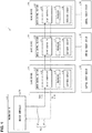
Fig. 1 is a block diagram schematically illustrating a control system including: slave devices each including a main control section serving as a control device in an embodiment; and a master device. -
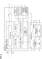
Fig. 2 is a block diagram illustrating a configuration of main parts of (i) a slave device including a main control section serving as a control device in the embodiment and (ii) a control target device connected to the slave device. -
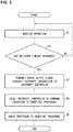
Fig. 3 is a flowchart illustrating a flow of a process carried out by the main control section serving as a control device in the embodiment. -
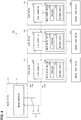
Fig. 4 is a block diagram schematically illustrating a configuration of a control system in accordance with Comparative Example. -
Fig. 5 is a flowchart illustrating a flow of an operation monitoring process carried out by a slave device included in the control system in accordance with Comparative Example. - The following description will discuss an embodiment in accordance with an aspect of the present disclosure (also referred to as "present embodiment") with reference to the drawings.
- For easy understanding of a control system and a control device in accordance with the embodiment, a control system in accordance with Comparative Example will be first described with reference to
Figs. 4 and5 . The control system in accordance with Comparative Example includes a slave device in which a microcontroller and a communication controller are provided as individual chips.Fig. 4 is a block diagram schematically illustrating a configuration of acontrol system 100 in accordance with Comparative Example.Fig. 5 is a flowchart illustrating a flow of an operation monitoring process carried out by aslave device 120 included in thecontrol system 100 of Comparative Example. - As illustrated in
Fig. 4 , thecontrol system 100 in accordance with Comparative Example includes: amaster device 110;slave devices 120 connected to themaster device 110; andcontrol target devices 140. To themaster device 110, the threeslave devices 120, which are arranged in series, are connected Such a network form (topology) is also called "daisy-chain connection". Theslave devices 120 are communicably connected to themaster device 110 via a field network 130 (adownlink 131 and an uplink 132). Based on data communication with themaster device 110, theslave devices 120 control the correspondingcontrol target devices 140. - The
master device 110 includes amaster controller 111 configured to manage thefield network 130. Theslave devices 120 each include aslave controller 121 and amain control section 122. Themain control section 122 is, for example, a microcontroller which includes aprocessor 122a and awatchdog circuit 122b. - In each of the
slave devices 120, theslave controller 121 and themain control section 122 are provided as individual chips. Such aslave controller 121 is, for example, intended for an application specific integrated circuit (ASIC). - An operation of the
watchdog circuit 122b in each of theslave devices 120 in accordance with Comparative Example will be described below with reference toFig. 5 . - As illustrated in
Fig. 5 , thewatchdog circuit 122b monitors an operation of the main control section 122 (Step 101 (hereinafter abbreviated, such as "S101")). In a case where no watchdog timeout occurs (NO in S102), an operation of S101 is repeated. In a case where theprocessor 122a goes out of control so as to cause the occurrence of a watchdog timeout (YES in S102), thewatchdog circuit 122b resets (initializes) the operation of theprocessor 122a (S103). It should be noted that theslave controller 121 includes a processor (not illustrated) therein. In the case where the watchdog timeout occurs, the processor is not reset. - According to the configuration of the
control system 100 of Comparative Example, theslave controllers 121 do not stop operating in a case where a watchdog timeout has occurred This allows communication via thefield network 130 to be continued. - However, in recent years, there are cases where a slave controller is embedded in a microcontroller which is provided in a slave device. In such a case, the occurrence of a watchdog timeout causes an operation of the slave controller to stop. This unfortunately interrupts the communication via the field network.
- An example in which the present disclosure is applied will be described next with reference to
Fig. 1. Fig. 1 is a block diagram schematically illustrating a control system 1 including:slave devices 3a through 3c each including amain control section 30 serving as a control device in the present embodiment; and amaster device 2. To each of theslave devices 3a through 3c, acontrol target device 50 is communicably connected. The control system 1 of the present embodiment is configured so that theslave devices 3a through 3c control the correspondingcontrol target devices 50 in accordance with a command transmitted from themaster device 2 via afield network 40. The field network is also referred to as "field bus system". Hereinafter, theslave devices 3a through 3c will also be collectively referred to as "slave devices 3" when no distinction is to be made. - In the example shown in
Fig. 1 , the control system 1 includes: themaster device 2; the threeslave devices 3a through 3c which are communicably connected to themaster device 2 via thefield network 40; and thecontrol target devices 50. Theslave devices 3a through 3c control the correspondingcontrol target devices 50 based on data communication with themaster device 2. - The
master device 2 is, for example, a PLC. To themaster device 2, a support device (not illustrated) such as a personal computer (PC) is connected via a connection cable. Themaster device 2 includes amaster controller 2a which manages data transmission to/from theslave devices 3a through 3c via thefield network 40. Examples of themaster controller 2a encompass a microcontroller andASIC. - The
field network 40 in the control system 1 of the present embodiment is Ethernet for Control Automation Technology (EtherCAT) (registered trademark). EtherCAT is a communication system based on Ethernet (registered trademark), and has been widely used in recent years. According to EtherCAT, a master device periodically transmits Ethernet protocols (Ethernet frames) in accordance with IEEE802.3 via Ethernet (transmission line), and, by an on-the-fly method, slave devices handle process data carried on the Ethernet frames. - A topology of the
field network 40 in the control system 1 of the present embodiment is a daisy-chain type. Specifically the threeslave devices 3a through 3c are arranged in series to be connected to themaster device 2 via thefield network 40. - Because the data transmission on EtherCAT is known, a detailed explanation will be omitted to avoid redundancy. Abrief description is as follows. In a case where the
slave device 3a has received an Ethernet frame which is periodically transmitted from themaster device 2, theslave device 3a reads and writes data from/to a region of process data on the Ethernet frame, which region is allocated to theslave device 3a. While theslave device 3a reads and writes the data, theslave device 3a forwards the Ethernet frame to theslave device 3b which is a next slave device. - The
field network 40 includes adownlink 41 and anuplink 42. An Ethernet frame is transmitted from themaster device 2 to theslave device 3a, to theslave device 3b, and to the slave device 3c in this order via thedownlink 41. Then, the Ethernet frame is transmitted from the slave device 3c to theslave device 3b, to theslave device 3a, to themaster device 2 in this order via theuplink 42. - The
slave devices 3a through 3c each include amain control section 30. Themain control section 30 includes a slave controller (slave communication controller) 31, a processor (processing section) 32, and a watchdog circuit (operation monitoring section) 33. Theslave controller 31 controls communication carried out via thefield network 40. Theprocessor 32 is, for example, a CPU. Theprocessor 32 sends and receives data to/from theslave controller 31 so as to carry out arithmetic processing for the control carried out by themain control section 30. Thewatchdog circuit 33 is an operation monitoring section for monitoring whether or not themain control section 30 is operating normally. - Because a method by which the
watchdog circuit 33 monitors the operation of themain control section 30 is generally known, a detailed explanation will be omitted to avoid redundancy. Abrief description is as follows. For example, before a counter of the watchdog timer times out, the counter is reset by a program. This operation of resetting the counter is carried out periodically as part of a program to be executed by theprocessor 32. Hereinafter, a resetting operation to reset the counter will be referred to as "refreshing" to be distinguished from an operation to reset theprocessor 32. In a case where theprocessor 32 goes out of control, theprocessor 32 no longer refreshes, so that an overflow of a timer occurs. In such a case, thewatchdog circuit 33 resets theprocessor 32. Note that the counting of the timer can be countdown from a certain initial value. - The
main control section 30 is, for example, a microcontroller, and is configured as a one-chip integrated circuit. Themain control section 30 includes a memory and various peripheral functional parts (not illustrated). - The
control target devices 50 connected to the corresponding ones of theslave devices 3a through 3c are, for example, servomotors. A variety of devices can be applied to thecontrol target devices 50, provided that the devices meet the standards of thefield network 40. - The
main control section 30 included in each of theslave devices 3a through 3c is thus configured so that theslave controller 31, theprocessor 32, and thewatchdog circuit 33 are provided on a single chip (i.e., is a one-chip device). Note themain control section 30, of course, includes circuits having other functions. - Such a configuration conventionally poses the following problem (which will be explained with use of the reference signs shown in
Fig. 1 ): Conventionally, in a case where a watchdog timeout occurs, thewatchdog circuit 33 resets theprocessor 32 and theslave controller 31. This unfortunately disrupts communication between themaster device 2 and theslave devices 3a through 3c via thefield network 40. An effect of such disruption is significant in a case where theslave devices 3a through 3c are of a daisy-chain type topology. In a case of, for example, data transmission on EtherCAT, theentire field network 40 is forced to stop if aslave controller 31 of any of theslave devices 3a through 3c stops. - In contrast, according to the control system 1 of the present embodiment, in a case where a watchdog timeout occurs, the
watchdog circuit 33 resets theprocessor 32, but does not stop the operation of theslave controller 31. In addition, in a case where a watchdog timeout occurs, thewatchdog circuit 33 transmits an error output signal (also referred to as "ERROROUT signal") which stops only part of the functions of theslave device 3. Therefore, in a case where a watchdog timeout occurs, communication by theslave controller 31 can be continued This makes it easy to inform themaster device 2 which of theslave devices 3 has encountered a malfunction. Then, a user easily can recover the control system 1 by referring to such information. In particular, in a case where theslave devices 3 are of daisy chain (series) topology (sequence), it is possible to continue communicating with the other slaves. This prevents theentire field network 40 from being forced to stop. - In addition, while an error output signal transmitted by the
watchdog circuit 33 is used to block an output of, for example, theslave device 3, thewatchdog circuit 33 carries out control so that an input from the outside into theslave device 3 is not blocked. This increases the degree of freedom in during-error operation carried out by theslave device 3 in a case where a watchdog timeout occurs. - An example of a hardware configuration of main parts of the control system 1 of the present embodiment will be described next with reference to
Fig. 2 . Specifically, theslave device 3a out of theslave devices 3a through 3c will be described as an example. The configuration of the main parts of theslave device 3a and the correspondingcontrol target device 50 will be described belowFig. 2 is a block diagram illustrating the configuration of the main parts of (i) theslave device 3a including themain control section 30 serving as a control device in the present embodiment and (ii) thecontrol target device 50 connected to theslave device 3a. Note that inFig. 2 , each arrow indicates a flow in which a signal is transmitted during a watchdog timeout. The flow will be described later. - In the example shown in
Fig. 2 , theslave device 3a includes themain control section 30, a notifyingsection 35, a reset circuit (external reset circuit) 36, and acommunication interface 37. Themain control section 30 of the present embodiment corresponds to "control device" of the present disclosure. InFig. 2 , the communication interface is indicated as "communication IF". - The
main control section 30 includes theslave controller 31, theprocessor 32, awatchdog timer 33a, anerror control module 33b, an interruptcontroller 33c, and astorage section 34. Thewatchdog timer 33a, theerror control module 33b, and the interruptcontroller 33c correspond to thewatchdog circuit 33 described earlier. - The
watchdog timer 33a is, for example, a stand-alone watchdog timer which is generally known. Thewatchdog timer 33a includes, for example, a 14-bit down counter. In a case where a count value reaches a value of an underflow, thewatchdog timer 33a transmits, to theerror control module 33b, an error notification (hereinafter referred to as "malfunction occurrence signal") which indicates that a malfunction has occurred in the operation of themain control section 30. Note that thewatchdog timer 33a can include an up counter. In such a case, thewatchdog timer 33a transmits a malfunction occurrence signal in a case where the count value reaches a value of an overflow. Examples of the counter encompass an RC oscillator circuit. - In a case where the
error control module 33b receives the malfunction occurrence signal from thewatchdog timer 33a, i.e., in a case where the malfunction has occurred in the operation of themain control section 30, theerror control module 33b carries out, independently of theprocessor 32, control of a during-malfunction operation of themain control section 30. In other words, theerror control module 33b is a during-malfunction operation control section for carrying out an operation such as generating an interrupt signal and/or transmitting an error output signal. Theerror control module 33b is achieved as an electronic circuit in themain control section 30 serving as a one-chip integrated circuit. - In response to a command from the
error control module 33b, the interruptcontroller 33c forcibly interrupts (i.e., non-maskable interruption) theprocessor 32. - The
storage section 34 is, for example, a memory including a random access memory (RAM) and a read only memory (ROM). ROM stores, for example, a program executed by theprocessor 32. RAM is used as a working area. Thestorage section 34 also stores register values for setting the respective operations of the parts of themain control section 30. - The following will be described later in detail: (i) the processes carried out by the
error control module 33b and the interruptcontroller 33c during a watchdog timeout and (ii) the register values stored in thestorage section 34. - Examples of the notifying
section 35 encompass a light emitting diode (LED), a speaker, and a display. The notifyingsection 35 provides various information to the outside of theslave device 3a. For example, during a watchdog timeout, the notifyingsection 35 provides malfunction information which indicates that theslave device 3a is encountering a malfunction. The notifyingsection 35 provides information by, for example, turning on the LED. A specific way by which the notifyingsection 35 provides malfunction information is not limited to any particular one. - The
reset circuit 36 is a circuit generally included in various electrical apparatuses so as to reset the operations of the apparatuses in accordance with external reset signals. When a power supply of theslave device 3a is turned on, thereset circuit 36 transmits, to the interruptcontroller 33c, a command for resetting the operation of themain control section 30. - The
communication interface 37 includes a receivingsection 37a and a transmitting section (output section) 37b. Thecommunication interface 37 is communicably connected to thecontrol target device 50 to send and receive data. According to theslave device 3a of the present embodiment, during a watchdog timeout, the operation of the receivingsection 37a continues, whereas output from the transmitting section 37b stops. This configuration will be described later. - In the example shown in
Fig. 2 , thecontrol target device 50 includes acommunication interface 51, amotor control section 52, amotor 53, and anencoder 54. - The
communication interface 51 receives a control signal transmitted from theslave device 3a, and then transmits the control signal to themotor control section 52. Themotor control section 52 is, for example, a microcontroller. Themotor control section 52 controls the operation of themotor 53. - The
encoder 54 includes anencoder control section 54a and asensor 54b. Theencoder control section 54a is, for example, a microcontroller. Theencoder control section 54a detects the rotation of themotor 53 with use of thesensor 54b. Then, theencoder control section 54a transmits, to themotor control section 52, information indicating the detection. - A specific hardware configuration of the
slave device 3a can be changed according to an embodiment. Specifically, any of omission, replacement, and addition of a component(s) is possible as appropriate. A specific configuration of the control system 1, in which theslave device 3a is included, can also be designed as appropriate according to an embodiment. - An example, in which the
slave device 3a including themain control section 30 as a control device of the present embodiment operates during a watchdog timeout, will be described next with reference toFigs. 2 and3. Fig. 3 is a flowchart illustrating a flow of a process carried out by themain control section 30 serving as a control device in the present embodiment. Note that a procedure described below is merely an example, and each step can be changed as much as possible. Note also that the procedure described below can be changed according to an embodiment. Specifically, any of omission, replacement, and addition of a step(s) is possible as appropriate. - A user first activates the control system 1, so that the
master device 2 and theslave devices 3a through 3c are activated. Process data carried on an Ethernet frame is transmitted from themaster device 2 to theslave device 3a via thefield network 40. In theslave device 3a, the counter of thewatchdog timer 33a is activated, so that thewatchdog circuit 33 monitors the operation of the main control section 30 (S1). - In a case where no watchdog timeout occurs (NO in S2), the
slave device 3a repeats the process in S1. In a case where a watchdog timeout occurs (YES in S2), thewatchdog timer 33a transmits a malfunction occurrence signal to theerror control module 33b. - In a case where the
error control module 33b has received the malfunction occurrence signal, theerror control module 33b transmits an interrupt instruction to the interruptcontroller 33c (S3). In accordance with the instruction, the interruptcontroller 33c commands theprocessor 32 to carry out an interrupt procedure (S4). In response to the command for the interrupt procedure, theprocessor 32 resets the operation of the processor 32 (S5) (operation malfunction controlling step). - Meanwhile, the
error control module 33b controls the interruptcontroller 33c so as to prevent the operation of theslave controller 31 from being reset. This can be achieved by, for example, masking part of the interrupt instruction which is transmitted from theerror control module 33b to the interruptcontroller 33c. Specifically, a register, which sets the procedure (output signal) to be carried out when theerror control module 33b receives the malfunction occurrence signal, is changed so that the operation of theslave controller 31 will not be reset. - This configuration makes it possible that in a case where a watchdog timeout occurs, the operation of the
processor 32 is reset, whereas the operation of theslave controller 31 is continued - In S3, the
error control module 33b transmits anerror output signal 60 together with the command for the interrupt procedure. Theerror output signal 60 is transmitted to thecontrol target device 50, to the notifyingsection 35, and to thecommunication interface 37. - The transmission of the
error output signal 60 can be set, for example, as follows: There is a register for setting whether or not an output of theerror output signal 60 is to be masked. Theerror control module 33b outputs theerror output signal 60 in accordance with a value of the register. In a case where an unmaskederror output signal 60 occurs, the output of a signal terminal becomes active (Low). The setting for transmission of theerror output signal 60 can be changed by changing the setting of the register. - Conventionally, in a case where a malfunction occurs to an operation of a slave device serving as a high-level control device, a control signal from the slave device is lost, so that a servomotor stops free running. In this case, it may take a long period of time until the motor stops. This may unfortunately cause a problem of the operation of the entire control system.
- According to the
slave device 3a of the present embodiment, in contrast, theerror output signal 60 is transmitted to thecontrol target device 50. By receiving theerror output signal 60, themotor control section 52 and theencoder control section 54a recognize that a malfunction has occurred in the operation of themain control section 30. This allows, upon receipt of theerror output signal 60, themotor control section 52 and theencoder control section 54a to carry out control so as to slow down and stop themotor 53. It is therefore possible to stop the operation of themotor 53 more quickly. As a result, it is possible to increase stability of the operation of the control system 1. - The notifying
section 35 includes, for example, a plurality of LEDs for providing various information. In a case where the notifyingsection 35 has received theerror output signal 60, the notifyingsection 35 then (i) turns on an error LED for indicating such malfunction information that a malfunction has occurred in the operation of themain control section 30 and (ii) turns off the other LEDs. This makes it easy to provide a user with the malfunction information. - In a case where the notifying
section 35 is, for example, a speaker, the notifyingsection 35 can provide the user with the malfunction information by a sound or a voice. - The notifying
section 35 is configured so that in a case where theerror output signal 60 is received, the notifyingsection 35, as a circuit, blocks any outputs thereof other than an error notification it makes as, for example, an error LED. - In a case where the
communication interface 37 has received theerror output signal 60, thecommunication interface 37 blocks the transmitting section 37b from making an output. On the other hand, thecommunication interface 37 does not block the receivingsection 37a from receiving data. - With this configuration, it is possible to prevent abnormal data from being outputted as a result of the
main control section 30 going out of control. By use of the receivingsection 37a, it is possible to receive an external communication from outside theslave device 3a. - The
communication interface 37 is configured to block an output as a circuit in a case where thecommunication interface 37 has received theerror output signal 60. - The
storage section 34 stores registers for setting what control is to be carried out in response to respective error factors. The registers include, for example, an error output setting register, an inner-reset setting register, and an interrupt setting register. The interrupt setting register sets the control of non-maskable interruption to be carried out by theerror control module 33b. Theerror control module 33b collectively manages, for example, 94 error factors, and operates in accordance with the settings of the interrupt setting register. - Conventionally, the initial values of the registers stored in the
storage section 34 are set so that in a case where a watchdog timeout occurs, theerror control module 33b resets themain control section 30 itself as a microcontroller. - According to the present embodiment, in contrast, the initial settings of the registers are cancelled so as to change the register values stored in the
storage section 34. This allows themain control section 30 of the present embodiment to carry out the above-describedprocedures 1 and 2 in a case where an operation malfunction occurs. - In a case where a watchdog timeout occurs, the
error control module 33b transmits, to theslave controller 31, amalfunction notification signal 61 indicating that a malfunction has occurred in the operation of theslave device 3a. Themalfunction notification signal 61 is then transmitted to themaster device 2 via theslave controller 31 and thefield network 40. This transmission can be carried out by utilizing, for example, ALStatusCode of the Ethernet frame. - With this configuration, the
master device 2 can promptly recognize, via thefield network 40, that the malfunction has occurred in the operation of theslave device 3a. Based on such information, themaster device 2 can flexibly determine what control to carry out in response. - Effects below can be obtained with the present embodiment, the premise of which is the configuration in which the
slave controller 31, theprocessor 32, and thewatchdog circuit 33 are included in a one-chip microcontroller. Specifically, in a case where a watchdog timeout has occurred, theerror control module 33b transmits a command to the interruptcontroller 33c so as to (i) reset theprocessor 32 and (ii) not reset theslave controller 31. This prevents the operation of theslave controller 31 from being stopped, and therefore allows the communication of thefield network 40 to be continued In particular, in a case where, for example, thefield network 40 is EtherCAT, it is possible to prevent the operation of theentire field network 40 from being stopped. - In addition, the
error control module 33b transmits anerror output signal 60 in a case where a watchdog timeout has occurred. By receiving theerror output signal 60, the parts of theslave device 3a and thecontrol target device 50 can carry out suitable procedures. For example, thecontrol target device 50 can flexibly select an operation. While theslave device 3a blocks an output, theslave device 3a can still receive an external communication. In addition, theslave device 3a can provide, to the outside thereof, information indicating that an operation malfunction has occurred. Then, in the case where the watchdog timeout has occurred, theslave device 3a does not block the receivingsection 37a from receiving data. - The
error control module 33b can transmit amalfunction notification signal 61 to theslave controller 31 so as to notify themaster device 2 that a malfunction has occurred. - An embodiment of the present disclosure described in detail above is merely an example of the present disclosure in many points. It is of course possible to make various modifications and variations, provided that the scope of the present disclosure is not exceeded For example, variations described below can be made. In the following description, components similar to those in the embodiment will be given the same reference signs, and the descriptions of features similar to those in the embodiment will be omitted as appropriate. The variations below can be combined as appropriate.
- According to the embodiment above, the
field network 40 is, for example, EtherCAT However, the type of thefield network 40 is not limited to such an example. For example, thefield network 40 can be any of the various industrial Ethernets. Alternatively, thefield network 40 can be any of field networks, such as DeviceNet, other than an Ethernet. - According to the control system 1 of the embodiment above, the three
slave devices 3a through 3c are connected to themaster device 2 via a network topology of the daisy-chain type. However, the topology of the control system 1 is not limited to such an example, but can be selected as appropriate according to an embodiment. For example, the topology can be any of various ones, such as a ring type, a star type, and a tree type. In addition, the number of slave devices included in the control system is not limited - Control blocks of the main control section 30 (particularly, the
slave controller 31 and the processor 32) can be realized by a logic circuit (hardware) provided in an integrated circuit (IC chip) or the like or can be alternatively realized by software. - In the latter case, the
main control section 30 includes a computer that executes instructions of a program that is software realizing the foregoing functions. The computer for example, includes at least one processor and a computer-readable storage medium storing the program. An object of the present disclosure can be achieved by the processor of the computer reading and executing the program stored in the storage medium. Examples of the processor encompass a central processing unit (CPU). Examples of the storage medium encompass a "non-transitory tangible medium" such as a read only memory (ROM), a tape, a disk, a card, a semiconductor memory, and a programmable logic circuit. The computer may further include a random access memory (RAM) or the like in which the program is loaded The program can be made available to the computer via any transmission medium (such as a communication network or a broadcast wave) which allows the program to be transmitted. Note that an aspect of the present disclosure can also be achieved in the form of a computer data signal in which the program is embodied via electronic transmission and which is embedded in a carrier wave. - A control device in accordance with an aspect of the present invention is thus a control device provided in a slave device so as to control an operation of the slave device, which slave device is configured to be connected to a master device via a field network, the control device including: a slave communication controller configured to control communication carried out via the field network; a processing section configured to carry out arithmetic processing; and an operation monitoring section configured to monitor an operation of the control device, the slave communication controller, the processing section, and the operation monitoring section being configured as a one-chip integrated circuit, and the control device being configured so that in a case where the operation monitoring section has detected that a malfunction has occurred in the operation of the control device, the operation monitoring section resets the processing section while not stopping an operation of the slave communication controller.
- The control device includes the slave communication controller, the processing section, and the operation monitoring section which are configured as a one-chip integrated circuit. The operation monitoring section monitors whether or not the control device is operating normally. In a case where the operation monitoring section detects that a malfunction has occurred in the operation, the operation monitoring section initializes the control device. In general, in a case where a control device is initialized by an operation monitoring section included in a one-chip integrated circuit, not only a processing section but also a slave communication controller is initialized. In such a case, controlling of communication carried out by the slave communication controller is stopped, so that a field network is unfortunately blocked. For example, in a case where the field network is EtherCAT (registered trademark), the operation of the entire field network may be stopped.
- According to the above configuration, in contrast, the operation monitoring section resets the processing section, whereas the operation monitoring section does not stop the operation of the slave communication controller. This allows the operation of the slave communication controller to be continued in a case where the control device is initialized as a result of the occurrence of a malfunction in the operation of the control device. Consequently, the field network is not blocked. This allows communication between the master device and the slave device to be continued It is therefore possible to increase stability of a control system in which a master device controls a slave device. In particular, in a case of a control system configured so that a plurality of slave devices are connected to a master device in the form of a daisy chain, the control system can continue communication between (i) the slave device whose operation has encountered a malfunction and (ii) the other slave devices. The master device can confirm the respective statuses of the slave devices.
- The control device in accordance with the aspect can be configured so as to further include: an output section configured to supply a control signal to a control target device whose operation is controlled in accordance with a command transmitted from the control device, the operation monitoring section including a watchdog timer, a during-malfunction operation control section configured to control a during-malfunction operation in a case where the malfunction has occurred in the operation of the control device, and an interrupt controller, the control device being configured so that in a case where the during-malfunction operation control section has received from the watchdog timer a malfunction occurrence signal indicating that a watchdog timeout has occurred, the during-malfunction operation control section carries out control to (i) cause the interrupt controller to transmit an interrupt signal so as to reset the processing section and (ii) block the output section from supplying the control signal to the control target device.
- According to the configuration, the operation monitoring section can typically be a watchdog circuit. In a case where a watchdog timeout has occurred, the during-malfunction operation control section transmits an interruption command to the interrupt controller. In accordance with the command, the interrupt controller resets the processing section. Meanwhile, in the case where the watchdog timeout has occurred, the during-malfunction operation control section blocks output from the output section. This blocks a control signal from being transmitted to the control target device. It is therefore possible to prevent an abnormal control signal from being transmitted from the control device, which has gone out of control, to the control target device. The control target device can also stop operating. It is therefore possible to achieve a higher degree of safety in controlling of a control target device by a slave device.
- The control device in accordance with the aspect can be configured so that: in a case where the during-malfunction operation control section has received the malfunction occurrence signal, the during-malfunction operation control section transmits an error output signal; and the error output signal is a signal to be received by the control target device so as to cause the control target device to carry out control to stop an operation in the control target device.
- With the configuration, a control section (e.g., microcontroller) included in the control target device can be notified of a malfunction by use of an error output signal. The control section can therefore select how to control the operation of the control target device. For example, in a case where the control target device is a servomotor, the control section of the control target device can carry out control so as to slow down and stop the motor instead of control so as to stop free running of the motor. This makes it possible to more quickly stop the motor. It is therefore possible to achieve an even higher degree of safety in controlling of a control target device by a slave device.
- The control device in accordance with the aspect can be configured so as to further include: a notifying section configured to provide a notification of a state of the control device, the control device being configured so that in a case where the notifying section has received the error output signal, the notifying section provides, to an outside of the slave device, malfunction information indicating the malfunction has occurred in the control device.
- According to the configuration, the notifying section provides malfunction information in a case where a malfunction has occurred in the control device. Therefore, based on the malfunction information, a user can recognize that the malfunction has occurred in the control device. For example, the user can easily recognize which one of a plurality of slave devices connected to the field network has encountered a malfunction. This allows the user to easily handle the situation thus recognized
- The control device in accordance with the aspect can be configured so that: the field network is EtherCAT; and in a case where the during-malfunction operation control section has received the malfunction occurrence signal, the during-malfunction operation control section transmits information to the master device by use of a data frame of the EtherCAT, the information indicating that the malfunction has occurred in the control device.
- With the configuration, information indicating that a malfunction has occurred in the control device can be transmitted to the master device by utilizing a data frame in EtherCAT. This allows the master device to promptly recognize the information so as to select how to handle the operation malfunction of the slave device.
- A control method in accordance with an aspect of the present invention is a method of controlling an operation of a slave device which is configured to be connected to a master device via a field network, the slave device including: a main control section including a slave communication controller configured to control communication carried out via the field network; a processing section configured to carry out arithmetic processing; and an operation monitoring section configured to monitor an operation of the control device, the slave communication controller, the processing section, and the operation monitoring section being configured as a one-chip integrated circuit, the method including the step of carrying out, in a case where the operation monitoring section has detected that a malfunction has occurred in the operation of the control device, operation malfunction control so as to reset the processing section while not stopping an operation of the slave communication controller.
- With the configuration, the following can be achieved as in the case of the control device described earlier: In a case where a malfunction has occurred in the operation of the main control section of the slave device, communication carried out via the field network is continued
- The present disclosure is not limited to the embodiment, but can be altered by a skilled person in the art within the scope of the claims. The present disclosure also encompasses, in its technical scope, any embodiment derived by combining technical means disclosed in the above description.
-
- 2
- Master device
- 3a through 3c
- Slave device
- 30
- Main control section (control device)
- 31
- Slave controller (slave communication controller)
- 32
- Processor (processing section)
- 33
- Watchdog circuit (operation monitoring section)
- 33a
- Watchdog timer
- 33b
- Error control module (during-malfunction operation control section)
- 33c
- Interrupt controller
- 35
- Notifying section
- 36
- Reset circuit (external reset circuit)
- 37b
- Transmitting section (output section)
- 40
- Field network
- 50
- Control target device
- 60
- Error output signal
Claims (6)
- A control device provided in a slave device so as to control an operation of the slave device, which slave device is configured to be connected to a master device via a field network,
said control device comprising:a slave communication controller configured to control communication carried out via the field network;a processing section configured to carry out arithmetic processing; andan operation monitoring section configured to monitor an operation of the control device,the slave communication controller, the processing section, and the operation monitoring section being configured as a one-chip integrated circuit, andthe control device being configured so that in a case where the operation monitoring section has detected that a malfunction has occurred in the operation of the control device, the operation monitoring section resets the processing section while not stopping an operation of the slave communication controller. - The control device according to claim 1, further comprising:an output section configured to supply a control signal to a control target device whose operation is controlled in accordance with a command transmitted from the control device,the operation monitoring section includinga watchdog timer,a during-malfunction operation control section configured to control a during-malfunction operation in a case where the malfunction has occurred in the operation of the control device, andan interrupt controller,the control device being configured so that in a case where the during-malfunction operation control section has received from the watchdog timer a malfunction occurrence signal indicating that a watchdog timeout has occurred, the during-malfunction operation control section carries out control to (i) cause the interrupt controller to transmit an interrupt signal so as to reset the processing section and (ii) block the output section from supplying the control signal to the control target device.
- The control device according to claim 2, wherein:in a case where the during-malfunction operation control section has received the malfunction occurrence signal, the during-malfunction operation control section transmits an error output signals andthe error output signal is a signal to be received by the control target device so as to cause the control target device to carry out control to stop an operation in the control target device.
- The control device according to claim 3, further comprising:a notifying section configured to provide a notification of a state of the control device,the control device being configured so that in a case where the notifying section has received the error output signal, the notifying section provides, to an outside of the slave device, malfunction information indicating the malfunction has occurred in the control device.
- The control device according to any one of claims 2 through 4, wherein:the field network is EtherCAT; andin a case where the during-malfunction operation control section has received the malfunction occurrence signal, the during-malfunction operation control section transmits information to the master device by use of a data frame of the EtherCAT, the information indicating that the malfunction has occurred in the control device.
- A method of controlling an operation of a slave device which is configured to be connected to a master device via a field network,
said slave device comprising:a main control section includinga slave communication controller configured to control communication carried out via the field network;a processing section configured to carry out arithmetic processing; andan operation monitoring section configured to monitor an operation of the main control section,the slave communication controller, the processing section, and the operation monitoring section being configured as a one-chip integrated circuit,said method comprising the step of
carrying out, in a case where the operation monitoring section has detected that a malfunction has occurred in the operation of the main control section, operation malfunction control so as to reset the processing section while not stopping an operation of the slave communication controller.
Applications Claiming Priority (2)
| Application Number | Priority Date | Filing Date | Title |
|---|---|---|---|
| JP2017199354A JP6922639B2 (en) | 2017-10-13 | 2017-10-13 | Control method of control device and slave device |
| PCT/JP2018/034907 WO2019073779A1 (en) | 2017-10-13 | 2018-09-20 | Control device, and slave device conrol method |
Publications (3)
| Publication Number | Publication Date |
|---|---|
| EP3696628A1 true EP3696628A1 (en) | 2020-08-19 |
| EP3696628A4 EP3696628A4 (en) | 2021-07-14 |
| EP3696628B1 EP3696628B1 (en) | 2022-02-16 |
Family
ID=66101473
Family Applications (1)
| Application Number | Title | Priority Date | Filing Date |
|---|---|---|---|
| EP18865979.1A Active EP3696628B1 (en) | 2017-10-13 | 2018-09-20 | Control device, and slave device conrol method |
Country Status (5)
| Country | Link |
|---|---|
| US (1) | US10884962B2 (en) |
| EP (1) | EP3696628B1 (en) |
| JP (1) | JP6922639B2 (en) |
| CN (1) | CN111052007B (en) |
| WO (1) | WO2019073779A1 (en) |
Families Citing this family (3)
| Publication number | Priority date | Publication date | Assignee | Title |
|---|---|---|---|---|
| US11138140B2 (en) * | 2020-01-31 | 2021-10-05 | Hewlett Packard Enterprise Development Lp | Configuring first subsystem with a master processor and a second subsystem with a slave processor |
| JP7575955B2 (en) * | 2021-01-13 | 2024-10-30 | キヤノン株式会社 | CONTROL DEVICE, SYSTEM, LITHOGRAPHIC APPARATUS, PROCESS FOR MANUFACTURING ARTICLE, CONTROL METHOD, AND PROGRAM |
| CN115167225A (en) * | 2022-07-25 | 2022-10-11 | 上海宇航系统工程研究所 | Solar cell wing driving control system capable of automatically switching on-orbit faults |
Family Cites Families (17)
| Publication number | Priority date | Publication date | Assignee | Title |
|---|---|---|---|---|
| JPS63224446A (en) | 1987-03-13 | 1988-09-19 | Furukawa Electric Co Ltd:The | Communication system |
| JPH0669017U (en) * | 1993-03-17 | 1994-09-27 | 株式会社東海理化電機製作所 | Vehicle control device |
| JPH07231489A (en) | 1994-02-17 | 1995-08-29 | Omron Corp | Control device with watchdog diagnostic function |
| JP2001060949A (en) * | 1999-08-23 | 2001-03-06 | Matsushita Electric Ind Co Ltd | Communication network system and operating state monitoring method thereof |
| JP4296050B2 (en) * | 2003-07-14 | 2009-07-15 | 三菱電機株式会社 | Electronic control unit |
| JP2008278403A (en) * | 2007-05-07 | 2008-11-13 | Fujitsu Ten Ltd | Monitoring apparatus and method of network system |
| JP2011258003A (en) | 2010-06-09 | 2011-12-22 | Hitachi Industrial Equipment Systems Co Ltd | Programmable controller |
| JP5496417B2 (en) * | 2011-05-11 | 2014-05-21 | 三菱電機株式会社 | Information processing apparatus, information processing method, and program |
| JP5825867B2 (en) * | 2011-06-14 | 2015-12-02 | 新電元工業株式会社 | Monitoring device, monitoring method, monitoring program, and monitoring system |
| JP5968119B2 (en) * | 2012-06-27 | 2016-08-10 | キヤノン株式会社 | Communication system with cascade connection |
| SG2013051982A (en) * | 2013-07-04 | 2015-02-27 | Pteris Global Ltd | Motor drive controller |
| JP6442843B2 (en) * | 2014-03-14 | 2018-12-26 | オムロン株式会社 | Control device |
| JP2015232761A (en) | 2014-06-09 | 2015-12-24 | 株式会社ジェイテクト | Vehicle control device and steering device |
| DE102015106026B3 (en) * | 2015-04-20 | 2016-08-25 | Interroll Holding Ag | Method for exchanging a control unit in a conveyor device |
| JP6424852B2 (en) * | 2016-03-10 | 2018-11-21 | オムロン株式会社 | Motor control device, control method, information processing program, and recording medium |
| JP6709086B2 (en) * | 2016-03-15 | 2020-06-10 | 株式会社日立産機システム | Communication control device and communication control method |
| CN106534177A (en) * | 2016-12-08 | 2017-03-22 | 武汉万千无限科技有限公司 | Multifunctional computer network safety control system |
-
2017
- 2017-10-13 JP JP2017199354A patent/JP6922639B2/en active Active
-
2018
- 2018-09-20 WO PCT/JP2018/034907 patent/WO2019073779A1/en not_active Ceased
- 2018-09-20 US US16/643,605 patent/US10884962B2/en active Active
- 2018-09-20 CN CN201880056218.5A patent/CN111052007B/en active Active
- 2018-09-20 EP EP18865979.1A patent/EP3696628B1/en active Active
Also Published As
| Publication number | Publication date |
|---|---|
| WO2019073779A1 (en) | 2019-04-18 |
| JP6922639B2 (en) | 2021-08-18 |
| CN111052007A (en) | 2020-04-21 |
| EP3696628A4 (en) | 2021-07-14 |
| US10884962B2 (en) | 2021-01-05 |
| JP2019074844A (en) | 2019-05-16 |
| EP3696628B1 (en) | 2022-02-16 |
| CN111052007B (en) | 2023-02-17 |
| US20200210362A1 (en) | 2020-07-02 |
Similar Documents
| Publication | Publication Date | Title |
|---|---|---|
| EP2816428B1 (en) | Control device, and control method | |
| EP3696628B1 (en) | Control device, and slave device conrol method | |
| US9612893B2 (en) | Peripheral watchdog timer | |
| US10649820B2 (en) | Method of managing event generation for an industrial controller | |
| US20050149207A1 (en) | Control system | |
| JP5682323B2 (en) | Safety control system | |
| US20110219157A1 (en) | Data processing device, semiconductor integrated circuit device, and abnormality detection method | |
| KR20110085425A (en) | Safety extension base and control method | |
| CN111522757A (en) | I2C bus-based interrupt reading and clearing control method | |
| EP3306423B1 (en) | Control apparatus | |
| JP6049961B1 (en) | CPU monitoring device | |
| CN109815044A (en) | A kind of cascade watchdog circuit | |
| US11054879B2 (en) | Safety controller | |
| JP6151655B2 (en) | Numerical controller | |
| JP2015175239A (en) | Monitoring device, monitoring method, and program | |
| KR101273812B1 (en) | Control module for programmable logic controller and control system using the control module | |
| JP2017151646A (en) | Control system, host controller, and mounting/demounting method of sub controller | |
| JPS61290836A (en) | Data transmission control system | |
| KR102104967B1 (en) | Duplicated board setting method and the board thereof | |
| JP7739716B2 (en) | Communication unit, network system, output unit control method and control program | |
| JP6906369B2 (en) | Computer systems, their control methods, and programs | |
| CN210666747U (en) | Fault self-recovery homologous clock system of server | |
| JPH0679279B2 (en) | Supervisory control device for microprocessor-applied equipment | |
| JP5489880B2 (en) | Central processing unit, control system, and port setting method | |
| JP2011134063A (en) | Watchdog timer |
Legal Events
| Date | Code | Title | Description |
|---|---|---|---|
| STAA | Information on the status of an ep patent application or granted ep patent |
Free format text: STATUS: THE INTERNATIONAL PUBLICATION HAS BEEN MADE |
|
| PUAI | Public reference made under article 153(3) epc to a published international application that has entered the european phase |
Free format text: ORIGINAL CODE: 0009012 |
|
| STAA | Information on the status of an ep patent application or granted ep patent |
Free format text: STATUS: REQUEST FOR EXAMINATION WAS MADE |
|
| 17P | Request for examination filed |
Effective date: 20200303 |
|
| AK | Designated contracting states |
Kind code of ref document: A1 Designated state(s): AL AT BE BG CH CY CZ DE DK EE ES FI FR GB GR HR HU IE IS IT LI LT LU LV MC MK MT NL NO PL PT RO RS SE SI SK SM TR |
|
| AX | Request for extension of the european patent |
Extension state: BA ME |
|
| DAV | Request for validation of the european patent (deleted) | ||
| DAX | Request for extension of the european patent (deleted) | ||
| REG | Reference to a national code |
Ref country code: DE Ref legal event code: R079 Ref document number: 602018031044 Country of ref document: DE Free format text: PREVIOUS MAIN CLASS: G05B0019050000 Ipc: G06F0011070000 |
|
| A4 | Supplementary search report drawn up and despatched |
Effective date: 20210610 |
|
| RIC1 | Information provided on ipc code assigned before grant |
Ipc: G06F 11/07 20060101AFI20210604BHEP Ipc: H04L 12/40 20060101ALI20210604BHEP Ipc: H04L 12/24 20060101ALI20210604BHEP Ipc: G05B 19/05 20060101ALI20210604BHEP Ipc: G05B 19/042 20060101ALI20210604BHEP Ipc: B60W 50/02 20120101ALI20210604BHEP |
|
| GRAP | Despatch of communication of intention to grant a patent |
Free format text: ORIGINAL CODE: EPIDOSNIGR1 |
|
| STAA | Information on the status of an ep patent application or granted ep patent |
Free format text: STATUS: GRANT OF PATENT IS INTENDED |
|
| INTG | Intention to grant announced |
Effective date: 20211117 |
|
| GRAS | Grant fee paid |
Free format text: ORIGINAL CODE: EPIDOSNIGR3 |
|
| GRAA | (expected) grant |
Free format text: ORIGINAL CODE: 0009210 |
|
| STAA | Information on the status of an ep patent application or granted ep patent |
Free format text: STATUS: THE PATENT HAS BEEN GRANTED |
|
| AK | Designated contracting states |
Kind code of ref document: B1 Designated state(s): AL AT BE BG CH CY CZ DE DK EE ES FI FR GB GR HR HU IE IS IT LI LT LU LV MC MK MT NL NO PL PT RO RS SE SI SK SM TR |
|
| REG | Reference to a national code |
Ref country code: GB Ref legal event code: FG4D |
|
| REG | Reference to a national code |
Ref country code: CH Ref legal event code: EP |
|
| REG | Reference to a national code |
Ref country code: DE Ref legal event code: R096 Ref document number: 602018031044 Country of ref document: DE |
|
| REG | Reference to a national code |
Ref country code: AT Ref legal event code: REF Ref document number: 1469318 Country of ref document: AT Kind code of ref document: T Effective date: 20220315 |
|
| REG | Reference to a national code |
Ref country code: IE Ref legal event code: FG4D |
|
| REG | Reference to a national code |
Ref country code: LT Ref legal event code: MG9D |
|
| REG | Reference to a national code |
Ref country code: NL Ref legal event code: MP Effective date: 20220216 |
|
| REG | Reference to a national code |
Ref country code: AT Ref legal event code: MK05 Ref document number: 1469318 Country of ref document: AT Kind code of ref document: T Effective date: 20220216 |
|
| PG25 | Lapsed in a contracting state [announced via postgrant information from national office to epo] |
Ref country code: SE Free format text: LAPSE BECAUSE OF FAILURE TO SUBMIT A TRANSLATION OF THE DESCRIPTION OR TO PAY THE FEE WITHIN THE PRESCRIBED TIME-LIMIT Effective date: 20220216 Ref country code: RS Free format text: LAPSE BECAUSE OF FAILURE TO SUBMIT A TRANSLATION OF THE DESCRIPTION OR TO PAY THE FEE WITHIN THE PRESCRIBED TIME-LIMIT Effective date: 20220216 Ref country code: PT Free format text: LAPSE BECAUSE OF FAILURE TO SUBMIT A TRANSLATION OF THE DESCRIPTION OR TO PAY THE FEE WITHIN THE PRESCRIBED TIME-LIMIT Effective date: 20220616 Ref country code: NO Free format text: LAPSE BECAUSE OF FAILURE TO SUBMIT A TRANSLATION OF THE DESCRIPTION OR TO PAY THE FEE WITHIN THE PRESCRIBED TIME-LIMIT Effective date: 20220516 Ref country code: NL Free format text: LAPSE BECAUSE OF FAILURE TO SUBMIT A TRANSLATION OF THE DESCRIPTION OR TO PAY THE FEE WITHIN THE PRESCRIBED TIME-LIMIT Effective date: 20220216 Ref country code: LT Free format text: LAPSE BECAUSE OF FAILURE TO SUBMIT A TRANSLATION OF THE DESCRIPTION OR TO PAY THE FEE WITHIN THE PRESCRIBED TIME-LIMIT Effective date: 20220216 Ref country code: HR Free format text: LAPSE BECAUSE OF FAILURE TO SUBMIT A TRANSLATION OF THE DESCRIPTION OR TO PAY THE FEE WITHIN THE PRESCRIBED TIME-LIMIT Effective date: 20220216 Ref country code: ES Free format text: LAPSE BECAUSE OF FAILURE TO SUBMIT A TRANSLATION OF THE DESCRIPTION OR TO PAY THE FEE WITHIN THE PRESCRIBED TIME-LIMIT Effective date: 20220216 Ref country code: BG Free format text: LAPSE BECAUSE OF FAILURE TO SUBMIT A TRANSLATION OF THE DESCRIPTION OR TO PAY THE FEE WITHIN THE PRESCRIBED TIME-LIMIT Effective date: 20220516 |
|
| PG25 | Lapsed in a contracting state [announced via postgrant information from national office to epo] |
Ref country code: PL Free format text: LAPSE BECAUSE OF FAILURE TO SUBMIT A TRANSLATION OF THE DESCRIPTION OR TO PAY THE FEE WITHIN THE PRESCRIBED TIME-LIMIT Effective date: 20220216 Ref country code: LV Free format text: LAPSE BECAUSE OF FAILURE TO SUBMIT A TRANSLATION OF THE DESCRIPTION OR TO PAY THE FEE WITHIN THE PRESCRIBED TIME-LIMIT Effective date: 20220216 Ref country code: GR Free format text: LAPSE BECAUSE OF FAILURE TO SUBMIT A TRANSLATION OF THE DESCRIPTION OR TO PAY THE FEE WITHIN THE PRESCRIBED TIME-LIMIT Effective date: 20220517 Ref country code: FI Free format text: LAPSE BECAUSE OF FAILURE TO SUBMIT A TRANSLATION OF THE DESCRIPTION OR TO PAY THE FEE WITHIN THE PRESCRIBED TIME-LIMIT Effective date: 20220216 Ref country code: AT Free format text: LAPSE BECAUSE OF FAILURE TO SUBMIT A TRANSLATION OF THE DESCRIPTION OR TO PAY THE FEE WITHIN THE PRESCRIBED TIME-LIMIT Effective date: 20220216 |
|
| PG25 | Lapsed in a contracting state [announced via postgrant information from national office to epo] |
Ref country code: IS Free format text: LAPSE BECAUSE OF FAILURE TO SUBMIT A TRANSLATION OF THE DESCRIPTION OR TO PAY THE FEE WITHIN THE PRESCRIBED TIME-LIMIT Effective date: 20220617 |
|
| PG25 | Lapsed in a contracting state [announced via postgrant information from national office to epo] |
Ref country code: SM Free format text: LAPSE BECAUSE OF FAILURE TO SUBMIT A TRANSLATION OF THE DESCRIPTION OR TO PAY THE FEE WITHIN THE PRESCRIBED TIME-LIMIT Effective date: 20220216 Ref country code: SK Free format text: LAPSE BECAUSE OF FAILURE TO SUBMIT A TRANSLATION OF THE DESCRIPTION OR TO PAY THE FEE WITHIN THE PRESCRIBED TIME-LIMIT Effective date: 20220216 Ref country code: RO Free format text: LAPSE BECAUSE OF FAILURE TO SUBMIT A TRANSLATION OF THE DESCRIPTION OR TO PAY THE FEE WITHIN THE PRESCRIBED TIME-LIMIT Effective date: 20220216 Ref country code: EE Free format text: LAPSE BECAUSE OF FAILURE TO SUBMIT A TRANSLATION OF THE DESCRIPTION OR TO PAY THE FEE WITHIN THE PRESCRIBED TIME-LIMIT Effective date: 20220216 Ref country code: DK Free format text: LAPSE BECAUSE OF FAILURE TO SUBMIT A TRANSLATION OF THE DESCRIPTION OR TO PAY THE FEE WITHIN THE PRESCRIBED TIME-LIMIT Effective date: 20220216 Ref country code: CZ Free format text: LAPSE BECAUSE OF FAILURE TO SUBMIT A TRANSLATION OF THE DESCRIPTION OR TO PAY THE FEE WITHIN THE PRESCRIBED TIME-LIMIT Effective date: 20220216 |
|
| REG | Reference to a national code |
Ref country code: DE Ref legal event code: R097 Ref document number: 602018031044 Country of ref document: DE |
|
| PG25 | Lapsed in a contracting state [announced via postgrant information from national office to epo] |
Ref country code: AL Free format text: LAPSE BECAUSE OF FAILURE TO SUBMIT A TRANSLATION OF THE DESCRIPTION OR TO PAY THE FEE WITHIN THE PRESCRIBED TIME-LIMIT Effective date: 20220216 |
|
| PLBE | No opposition filed within time limit |
Free format text: ORIGINAL CODE: 0009261 |
|
| STAA | Information on the status of an ep patent application or granted ep patent |
Free format text: STATUS: NO OPPOSITION FILED WITHIN TIME LIMIT |
|
| 26N | No opposition filed |
Effective date: 20221117 |
|
| PG25 | Lapsed in a contracting state [announced via postgrant information from national office to epo] |
Ref country code: SI Free format text: LAPSE BECAUSE OF FAILURE TO SUBMIT A TRANSLATION OF THE DESCRIPTION OR TO PAY THE FEE WITHIN THE PRESCRIBED TIME-LIMIT Effective date: 20220216 |
|
| PG25 | Lapsed in a contracting state [announced via postgrant information from national office to epo] |
Ref country code: MC Free format text: LAPSE BECAUSE OF FAILURE TO SUBMIT A TRANSLATION OF THE DESCRIPTION OR TO PAY THE FEE WITHIN THE PRESCRIBED TIME-LIMIT Effective date: 20220216 |
|
| REG | Reference to a national code |
Ref country code: CH Ref legal event code: PL |
|
| GBPC | Gb: european patent ceased through non-payment of renewal fee |
Effective date: 20220920 |
|
| REG | Reference to a national code |
Ref country code: BE Ref legal event code: MM Effective date: 20220930 |
|
| PG25 | Lapsed in a contracting state [announced via postgrant information from national office to epo] |
Ref country code: LU Free format text: LAPSE BECAUSE OF NON-PAYMENT OF DUE FEES Effective date: 20220920 |
|
| PG25 | Lapsed in a contracting state [announced via postgrant information from national office to epo] |
Ref country code: LI Free format text: LAPSE BECAUSE OF NON-PAYMENT OF DUE FEES Effective date: 20220930 Ref country code: IT Free format text: LAPSE BECAUSE OF FAILURE TO SUBMIT A TRANSLATION OF THE DESCRIPTION OR TO PAY THE FEE WITHIN THE PRESCRIBED TIME-LIMIT Effective date: 20220216 Ref country code: IE Free format text: LAPSE BECAUSE OF NON-PAYMENT OF DUE FEES Effective date: 20220920 Ref country code: FR Free format text: LAPSE BECAUSE OF NON-PAYMENT OF DUE FEES Effective date: 20220930 Ref country code: CH Free format text: LAPSE BECAUSE OF NON-PAYMENT OF DUE FEES Effective date: 20220930 |
|
| PG25 | Lapsed in a contracting state [announced via postgrant information from national office to epo] |
Ref country code: BE Free format text: LAPSE BECAUSE OF NON-PAYMENT OF DUE FEES Effective date: 20220930 |
|
| PG25 | Lapsed in a contracting state [announced via postgrant information from national office to epo] |
Ref country code: GB Free format text: LAPSE BECAUSE OF NON-PAYMENT OF DUE FEES Effective date: 20220920 |
|
| PG25 | Lapsed in a contracting state [announced via postgrant information from national office to epo] |
Ref country code: CY Free format text: LAPSE BECAUSE OF FAILURE TO SUBMIT A TRANSLATION OF THE DESCRIPTION OR TO PAY THE FEE WITHIN THE PRESCRIBED TIME-LIMIT Effective date: 20220216 |
|
| PG25 | Lapsed in a contracting state [announced via postgrant information from national office to epo] |
Ref country code: MK Free format text: LAPSE BECAUSE OF FAILURE TO SUBMIT A TRANSLATION OF THE DESCRIPTION OR TO PAY THE FEE WITHIN THE PRESCRIBED TIME-LIMIT Effective date: 20220216 Ref country code: HU Free format text: LAPSE BECAUSE OF FAILURE TO SUBMIT A TRANSLATION OF THE DESCRIPTION OR TO PAY THE FEE WITHIN THE PRESCRIBED TIME-LIMIT; INVALID AB INITIO Effective date: 20180920 |
|
| PG25 | Lapsed in a contracting state [announced via postgrant information from national office to epo] |
Ref country code: MT Free format text: LAPSE BECAUSE OF FAILURE TO SUBMIT A TRANSLATION OF THE DESCRIPTION OR TO PAY THE FEE WITHIN THE PRESCRIBED TIME-LIMIT Effective date: 20220216 |
|
| PGFP | Annual fee paid to national office [announced via postgrant information from national office to epo] |
Ref country code: DE Payment date: 20250919 Year of fee payment: 8 |
|
| PG25 | Lapsed in a contracting state [announced via postgrant information from national office to epo] |
Ref country code: TR Free format text: LAPSE BECAUSE OF FAILURE TO SUBMIT A TRANSLATION OF THE DESCRIPTION OR TO PAY THE FEE WITHIN THE PRESCRIBED TIME-LIMIT Effective date: 20220216 |