EP3696529A1 - Method for quantitative analysis of polymer using maldi mass spectrometry, and method for manufacturing sample for maldi mass spectrometry for quantitative analysis of polymer - Google Patents
Method for quantitative analysis of polymer using maldi mass spectrometry, and method for manufacturing sample for maldi mass spectrometry for quantitative analysis of polymer Download PDFInfo
- Publication number
- EP3696529A1 EP3696529A1 EP18867231.5A EP18867231A EP3696529A1 EP 3696529 A1 EP3696529 A1 EP 3696529A1 EP 18867231 A EP18867231 A EP 18867231A EP 3696529 A1 EP3696529 A1 EP 3696529A1
- Authority
- EP
- European Patent Office
- Prior art keywords
- polymer
- sample
- specimen
- quantitative analysis
- mass spectrometry
- Prior art date
- Legal status (The legal status is an assumption and is not a legal conclusion. Google has not performed a legal analysis and makes no representation as to the accuracy of the status listed.)
- Granted
Links
Images


Classifications
-
- G—PHYSICS
- G01—MEASURING; TESTING
- G01N—INVESTIGATING OR ANALYSING MATERIALS BY DETERMINING THEIR CHEMICAL OR PHYSICAL PROPERTIES
- G01N1/00—Sampling; Preparing specimens for investigation
- G01N1/28—Preparing specimens for investigation including physical details of (bio-)chemical methods covered elsewhere, e.g. G01N33/50, C12Q
- G01N1/2813—Producing thin layers of samples on a substrate, e.g. smearing, spinning-on
-
- G—PHYSICS
- G01—MEASURING; TESTING
- G01N—INVESTIGATING OR ANALYSING MATERIALS BY DETERMINING THEIR CHEMICAL OR PHYSICAL PROPERTIES
- G01N27/00—Investigating or analysing materials by the use of electric, electrochemical, or magnetic means
- G01N27/62—Investigating or analysing materials by the use of electric, electrochemical, or magnetic means by investigating the ionisation of gases, e.g. aerosols; by investigating electric discharges, e.g. emission of cathode
- G01N27/622—Ion mobility spectrometry
- G01N27/623—Ion mobility spectrometry combined with mass spectrometry
-
- G—PHYSICS
- G01—MEASURING; TESTING
- G01N—INVESTIGATING OR ANALYSING MATERIALS BY DETERMINING THEIR CHEMICAL OR PHYSICAL PROPERTIES
- G01N27/00—Investigating or analysing materials by the use of electric, electrochemical, or magnetic means
- G01N27/62—Investigating or analysing materials by the use of electric, electrochemical, or magnetic means by investigating the ionisation of gases, e.g. aerosols; by investigating electric discharges, e.g. emission of cathode
- G01N27/626—Investigating or analysing materials by the use of electric, electrochemical, or magnetic means by investigating the ionisation of gases, e.g. aerosols; by investigating electric discharges, e.g. emission of cathode using heat to ionise a gas
- G01N27/628—Investigating or analysing materials by the use of electric, electrochemical, or magnetic means by investigating the ionisation of gases, e.g. aerosols; by investigating electric discharges, e.g. emission of cathode using heat to ionise a gas and a beam of energy, e.g. laser enhanced ionisation
-
- G—PHYSICS
- G01—MEASURING; TESTING
- G01N—INVESTIGATING OR ANALYSING MATERIALS BY DETERMINING THEIR CHEMICAL OR PHYSICAL PROPERTIES
- G01N33/00—Investigating or analysing materials by specific methods not covered by groups G01N1/00 - G01N31/00
- G01N33/44—Resins; Plastics; Rubber; Leather
- G01N33/442—Resins; Plastics
-
- H—ELECTRICITY
- H01—ELECTRIC ELEMENTS
- H01J—ELECTRIC DISCHARGE TUBES OR DISCHARGE LAMPS
- H01J49/00—Particle spectrometers or separator tubes
- H01J49/0027—Methods for using particle spectrometers
- H01J49/0031—Step by step routines describing the use of the apparatus
-
- H—ELECTRICITY
- H01—ELECTRIC ELEMENTS
- H01J—ELECTRIC DISCHARGE TUBES OR DISCHARGE LAMPS
- H01J49/00—Particle spectrometers or separator tubes
- H01J49/02—Details
- H01J49/04—Arrangements for introducing or extracting samples to be analysed, e.g. vacuum locks; Arrangements for external adjustment of electron- or ion-optical components
- H01J49/0404—Capillaries used for transferring samples or ions
-
- H—ELECTRICITY
- H01—ELECTRIC ELEMENTS
- H01J—ELECTRIC DISCHARGE TUBES OR DISCHARGE LAMPS
- H01J49/00—Particle spectrometers or separator tubes
- H01J49/02—Details
- H01J49/04—Arrangements for introducing or extracting samples to be analysed, e.g. vacuum locks; Arrangements for external adjustment of electron- or ion-optical components
- H01J49/0409—Sample holders or containers
- H01J49/0418—Sample holders or containers for laser desorption, e.g. matrix-assisted laser desorption/ionisation [MALDI] plates or surface enhanced laser desorption/ionisation [SELDI] plates
-
- H—ELECTRICITY
- H01—ELECTRIC ELEMENTS
- H01J—ELECTRIC DISCHARGE TUBES OR DISCHARGE LAMPS
- H01J49/00—Particle spectrometers or separator tubes
- H01J49/02—Details
- H01J49/10—Ion sources; Ion guns
- H01J49/16—Ion sources; Ion guns using surface ionisation, e.g. field-, thermionic- or photo-emission
- H01J49/161—Ion sources; Ion guns using surface ionisation, e.g. field-, thermionic- or photo-emission using photoionisation, e.g. by laser
- H01J49/164—Laser desorption/ionisation, e.g. matrix-assisted laser desorption/ionisation [MALDI]
-
- H—ELECTRICITY
- H01—ELECTRIC ELEMENTS
- H01J—ELECTRIC DISCHARGE TUBES OR DISCHARGE LAMPS
- H01J49/00—Particle spectrometers or separator tubes
- H01J49/26—Mass spectrometers or separator tubes
- H01J49/34—Dynamic spectrometers
- H01J49/40—Time-of-flight spectrometers
-
- G—PHYSICS
- G01—MEASURING; TESTING
- G01N—INVESTIGATING OR ANALYSING MATERIALS BY DETERMINING THEIR CHEMICAL OR PHYSICAL PROPERTIES
- G01N1/00—Sampling; Preparing specimens for investigation
- G01N1/28—Preparing specimens for investigation including physical details of (bio-)chemical methods covered elsewhere, e.g. G01N33/50, C12Q
- G01N1/30—Staining; Impregnating ; Fixation; Dehydration; Multistep processes for preparing samples of tissue, cell or nucleic acid material and the like for analysis
- G01N1/31—Apparatus therefor
- G01N2001/317—Apparatus therefor spraying liquids onto surfaces
Definitions
- the present invention relates to a method for quantitative analysis of a polymer by MALDI mass spectrometry and a method for preparing a specimen for MALDI mass spectrometry for quantitative analysis of a polymer. More particularly, the present invention provides a method for quantitative analysis of a polymer and a method for preparing a specimen for MALDI mass spectrometry for quantitative analysis of a polymer, which enable to obtain a reproducible MALDI spectrum by using commercially available MALDI-TOF MS equipment.
- MALDI Microx-Assisted Laser Desorption Ionization
- the object of the present invention is to provide a method for quantitative analysis of a polymer using MALDI mass spectrometry by achieving a reproducible MALDI spectrum.
- Another object of the present invention is to provide a method for preparing a specimen of a polymer sample suitable for obtaining a reproducible MALDI spectrum for the polymer.
- the present invention provides a method for quantitative analysis of a polymer using MALDI mass spectrometry with a specimen prepared by electrospray of a polymer sample, which is a mixed solution of a polymer compound, a matrix and a solvent, from a main nozzle onto a sample plate through a mask, wherein a thickness deviation in the specimen is 30% or less, and the mask comprises a hole through which the polymer sample to be electrosprayed can be passed to the sample plate.
- the error range of measurement results of the MALDI spectrum on the same specimen may be within 30%.
- the error range of measurement results of the MALDI spectrum on at least three specimens prepared under the same condition may be within 30%.
- the method for quantitative analysis may be for measuring a polymer having a molecular weight of 1000 Da or more.
- the method for preparing a specimen for MALDI mass spectrometry for quantitative analysis of a polymer using the electrospray apparatus according to the present invention comprising a main nozzle for electrospray of a polymer sample which is a mixed solution of a polymer compound, a matrix and a solvent, and a sample plate on which the specimen is placed by electrospray of the polymer sample, the method comprising the steps of:
- the diameter of the hole may be 1 ⁇ m to 2 ⁇ m.
- the electrospray apparatus further comprises an auxiliary nozzle surrounding the main nozzle and coaxial with the main nozzle, and the step of performing electrospray of the polymer sample from the main nozzle onto the sample plate may further comprise spraying the solvent from the auxiliary nozzle to prevent the matrix from being deposited in the vicinity of the main nozzle.
- the electrospray apparatus further comprises a sheath gas supply pipe surrounding the auxiliary nozzle and coaxial with the auxiliary nozzle, and the step of performing electrospray of the polymer sample from the main nozzle onto the sample plate may further comprise jetting a sheath gas through the sheath gas supply pipe so that the sheath gas guides the polymer sample to be sprayed onto the predetermined position of the sample plate.
- the method comprises the steps of:
- the jetting area through electrospray is 80 mm 2 or less.
- the present invention provides a method for quantitative analysis of a polymer by MALDI mass spectrometry and a method for preparing a specimen for MALDI mass spectrometry for quantitative analysis of a polymer, in which the reproducibility of the MALDI spectrum can be further improved by uniformizing the thickness of the specimen that affects the pattern in the MALDI spectrum of polymer. Since the specimen according to the present invention is applicable to commercial MALDI-TOF equipment, quantitative analysis of the polymer can be performed more efficiently and quickly.
- the present invention provides a method for quantitative analysis of a polymer using MALDI mass spectrometry with a specimen prepared by electrospray of a polymer sample, which is a mixed solution of a polymer compound, a matrix and a solvent, from a main nozzle onto a sample plate through a mask, wherein a thickness deviation in the specimen is 40% or less, or 30% or less, or 20% or less and the mask comprises a hole through which the polymer sample to be electrosprayed can be passed to the sample plate.
- Fig. 2 shows the influence of the temperature change depending on the thickness of the specimen on the ionization efficiency of the polymer.
- the cause of the phenomenon can be predicted from the graph showing a change in binding energy of Na+ and polymer depending on the temperature.
- the graph on the right side of Fig. 2 is a graph of a change in binding energy of Na+ and polymer depending on the temperature.
- E(Na+) and E(polymer) refers to the energy of Na+ and polymer, respectively, and E(Na+, polymer) refers to the energy of the structure in which Na+ and polymer are combined.
- the optimized structure and energy of a molecule can be determined from density functional theory (DFT).
- DFT density functional theory
- the experimental result can be predicted by using a graph of the change in binding energy of Na+ and polymer depending on the temperature.
- a specimen having a thickness deviation of 40% or less, or 30% or less, or 20% or less, prepared by electrospray through a mask for measuring the MALDI spectrum of a polymer by using a specimen having a thickness deviation of 40% or less, or 30% or less, or 20% or less, prepared by electrospray through a mask for measuring the MALDI spectrum of a polymer, a reproducible MALDI spectrum can be obtained, thereby enabling quantitative analysis of the polymer.
- the MALDI spectrum of polymer according to the present invention may have 30% or less of RSD (Relative Standard Deviation) of results of three or more trials under same condition.
- RSD Relative Standard Deviation
- an error may be within 30%, preferably within 20%, and more preferably within 15%.
- Reproducible MALDI spectra can be obtained with an error within 30% even in the case of sample-to-sample evaluation for three or more specimens prepared under same condition.
- the present invention also provides a method for preparing a specimen of a polymer sample suitable for obtaining a reproducible MALDI spectrum of polymer as described above.
- a method for preparing a specimen for MALDI mass spectrometry for quantitative analysis of a polymer using an electrospray apparatus comprising a main nozzle for electrospray of a polymer sample which is a mixed solution of a polymer compound, a matrix and a solvent, and a sample plate on which the specimens are placed by electrospray of the polymer sample, the method comprising the steps of:
- the MALDI spectrum was measured by selecting only the center of the jetting region with the sample using electrospray through a mask. In this way, a uniform specimen with a small thickness deviation can be produced.
- the polymer specimen prepared by this method can be applied to a commercial MALDI-TOF MS equipment and provide a reproducible MALDI spectrum with error range within 30%. From this, it is possible to quantitatively analyze a polymer sample.
- the polymer sample can be sprayed and deposited more uniformly over a large area.
- Electrospray has a simple shape and structure of nozzle so that it is easy to be manufactured and it makes simple to generate several tens of micro-sized to several hundreds of nano-sized droplets.
- the droplets have a monodisperse distribution and the surface of the droplet is charged, there is an advantage that the droplets are hardly to be bonded to each other and it is easy to control the droplet.
- it is possible to manufacture a specimen which has a large area can be prepared by jetting at atmospheric pressure and has more stable characteristics due to electrostatic effect.
- a nozzle unit 100 of an electrospray apparatus 10 comprises a main nozzle 110 through which a mixed solution (hereinafter referred to as a "polymer sample” or a “sample") of a polymer compound, a matrix and a solvent, and an auxiliary nozzle 120 surrounding the main nozzle 110 and coaxial with the main nozzle 110 and the auxiliary nozzle 120 is configured to spray the solvent, as shown in Fig. 4a relating to a cross-sectional view of a nozzle used in the method of preparing a specimen through electrospray according to an embodiment of the present invention.
- a mixed solution hereinafter referred to as a "polymer sample” or a “sample”
- auxiliary nozzle 120 surrounding the main nozzle 110 and coaxial with the main nozzle 110 and the auxiliary nozzle 120 is configured to spray the solvent
- Fig. 4a solid arrows in the main nozzle 110 indicate a flow of the polymer sample jetted from the main nozzle 110
- arrows indicated by dotted lines in the auxiliary nozzle 120 indicate a flow of the polymer sample jetted from the auxiliary nozzle 120. That is, by jetting the solvent from the auxiliary nozzle 120 surrounding the main nozzle 110 while jetting the polymer sample from the main nozzle 110, it is possible to prevent deposition of the matrix at the end of the nozzle, which is a problem in the jetting process using electrospray according to the prior art, thereby improving the reproducibility of electrospray of the polymer sample. That is, the polymer sample to be electrosprayed from the main nozzle 110 can be sprayed to a predetermined position.
- a sheath gas supply pipe 130 surrounding the auxiliary nozzle 120 and coaxial with the auxiliary nozzle 120, when a polymer sample is sprayed through the main nozzle 110, the sheath gas is also sprayed around the polymer sample so that the sheath gas guides the polymer sample to be sprayed onto the predetermined position.
- a thick arrow in the sheath gas supply pipe 130 indicates a sheath gas jetted from the sheath gas supply pipe 130. Accordingly, the reproducibility of electrospray of the polymer sample can be improved.
- the sheath gas for example, nitrogen gas (N 2 ) may be used.
- the nitrogen gas can be released at 100cc to 1000cc per minute, and in one embodiment, 1000cc per minute.
- the solvent is jetted through an auxiliary nozzle 120 surrounding the main nozzle 110 or a sheath gas is jetted through a sheath gas supply pipe surrounding the auxiliary nozzle 120 and coaxial with the auxiliary nozzle 120 around the polymer sample to be jetted.
- a sheath gas is jetted through a sheath gas supply pipe surrounding the auxiliary nozzle 120 and coaxial with the auxiliary nozzle 120 around the polymer sample to be jetted.
- a mask 200 according to an embodiment of the present invention when preparing a specimen of a polymer compound, a mask 200 according to an embodiment of the present invention, and a unit for adjusting mask position 300 may be used. That is, when the polymer sample is electrosprayed onto the sample plate placed on the sample stage 210, a mask 200 that can be positioned on the sample plate is used. Thereby, the polymer sample can be selected so that only a portion with small thickness deviation can be selected as a specimen, among the regions to be spread widely on the sample plate placed on the sample stage 210 due to electrospray.
- the mask 200 may be mounted on the unit for adjusting mask position 300 and positioned on the sample plate, and the position of the mask 200 may be adjusted by the unit for adjusting mask position 300.
- the mask 200 At the center of the mask 200, there is a hole 200a having a size of substantially identical with a size of a specimen corresponding to a portion having a desired thickness deviation.
- the sample which cannot pass through the hole 200a among the samples to be electrosprayed remains on the mask 200.
- the polymer sample to be electrosprayed may be placed on the sample plate through the hole 200a of the mask 200 to obtain a specimen having a desired thickness deviation.
- a specimen having a desired thickness deviation remains on the sample stage 210.
- the material of the mask 200 is not particularly limited, and for example, stainless steel, aluminum, or the like can be used.
- the shape of the mask 200 may be, for example, a rectangular shape, a circular shape or the like, but the present invention is not limited thereto, and various modifications and variations are possible.
- the length of one side may be, for example, 1 mm to 2 mm
- the diameter may be 1 mm to 2 mm.
- the size of the hole 200a may be, for example, 1 ⁇ m to 2 ⁇ m in diameter.
- the unit for adjusting mask position 300 comprises a mask holder 310 on which the mask 200 can be mounted.
- the mask holder 310 may further comprise, in an embodiment, an opening 310a.
- the mask 200 may be mounted on the opening 310a and the mounted mask 200 may move on an axis in one direction (e.g., the y-axis).
- the opening 310a may have, for example, a rectangular shape, and the width of one side of the rectangular shape of opening 310a may coincide with the width of the mask 200.
- the width of the other side of the opening 310a is larger than the width of the mask 200 so that the mask 200 mounted on the opening 310a can be moved and mounted.
- a convex portion 310b is provided at both edges of the opening 310a. Accordingly, the mask 200 can be placed over the convex portion 310b of the opening 310a.
- the unit for adjusting mask position 300 comprises a linear motion rail 320 extending perpendicularly to the longitudinal direction of a mask holder 310.
- the mask holder 310 may be mounted on a mounting portion 320a of the linear motion rail 320.
- the mask holder 310 is fixed to the mounting portion 320a with bolts or the like so that it can move in the x-axis on a rail portion 320b of the linear motion rail 320.
- the rail portion 320b may further comprise a ruler (see Fig. 4d ) to indicate how much the mask holder 310, that is, the mask 200 mounted on the mask holder 310, moves in the x-axis.
- the mask 200 may move in the y-axis direction within the opening 310a of the mask holder 310 as described above.
- the unit for adjusting mask position 300 can adjust the height of the mask holder 310 in the z-axis direction (perpendicular to the upper surface of the sample stage 210).
- a plate of stainless steel, an ITO glass, or the like is variously used. Therefore, it is necessary to adjust the mask holder 310, that is, the height (height in the z-axis direction) of the mask 200 mounted on the mask holder 310, to match the height of the plate.
- a spacer 330 may be provided between the mask holder 310 and the mounting portion 320a to adjust the height of the mask holder 310. For example, while increasing the number of spacers from 0 (zero), a plurality of spacers may be provided until the corresponding height is reached, or a spacer having a height corresponding to the plate may be provided.
- the present invention is not limited to the embodiments described above, and various modifications and variations thereof are possible.
- the unit for adjusting mask position 300 according to the present invention may further comprise a fixing portion 340 for fixing the mask holder 310 on the linear motion rail 320.
- Fig. 4d shows a photograph of the mask 200 and the unit for adjusting mask position 300 of Fig. 4b and Fig. 4c which are implemented in one embodiment.
- the mask 200 according to Figs. 4b to 4d is placed on the sample plate so that only a portion with small thickness deviation can be selected as a specimen, among the regions to be spread widely when electrospraying the polymer sample on the sample plate on the sample stage 210, while in order to adjust the position of the mask 200, the movement in the z-axis direction of the mask holder 310 on which the mask 200 is mounted is controlled by the spacers 330 between the mask holder 310 and the linear motion rail 320, the movement in the x-axis direction of the mask holder 310 on which the mask 200 is mounted is controlled by the linear motion rail 320 and the movement in the y-axis direction of the mask 200, and the mask 200 can be moved in the y-axis direction within the opening 310a of the mask holder 310.
- the method of adjusting the position of the mask described above is an embodiment of a method of preparing a specimen using the mask of the present invention.
- the present invention is not limited to the above-described method, and various modifications and variations thereof are possible regarding the manner of adjusting the position of the mask.
- Fig. 4e shows a photograph of an embodiment of the electrospray apparatus 10 for producing a specimen according to the present invention.
- the main body 20 comprises the nozzle unit 100 including the main nozzle 110, the auxiliary nozzle 120 and the sheath gas supply pipe 130 of Fig. 4a , and the mask 200, the sample stage 210 and the unit for adjusting mask position 300 of Figs. 4b and 4c .
- a unit for adjusting injection amount of sample 30 may comprise a pump 30a for controlling the injection amount of the polymer sample supplied to the main nozzle 110 of Fig. 4a and a pump 30b for controlling the injection amount of the solvent supplied to the auxiliary nozzle 120.
- a unit for adjusting sheath gas 40 can regulate the amount of sheath gas supplied to the sheath gas supply pipe 130 of Fig. 4a .
- the jetting area through electrospray may be 80 mm 2 or less.
- the polymer that can be applied to MALDI mass spectrometry according to the present invention is not particularly limited as long as it is a polymer having a molecular weight of 1000 Da or more.
- a solution of the polymer compound of BHB-PPG/PPG dissolved in tetrahydrofuran (THF) was mixed with a solution (10 mg/ml) of a matrix (DCTB, trans-2-[3-(4-tert-butylphenyl)-2-methyl-2-propenylidene]malononitrile) and a NaTFA solution (0.02M in THF) at a volume ratio of 9: 1: 1 to prepare a polymer sample.
- DCTB matrix
- DCTB trans-2-[3-(4-tert-butylphenyl)-2-methyl-2-propenylidene]malononitrile
- NaTFA solution 0.02M in THF
- MALDI spectra were measured for six spots of each of two specimens prepared by the Dried droplet method (MALDI-TOF MS equipment: UltrafleXtreme, Bruker Daltonics, Germany).
- the MALDI-TOF spectra of the specimens prepared in Comparative Example 1 and Example 1 are shown in Fig. 6 . As shown in Fig. 6 , the reproducibility of spectrum is higher in the specimen of Example 1 manufactured using the electrospray and the mask.
- the specimens were prepared in the same manner as in Example 1, using the polymer samples having the BHB-PPG and PPG concentrations of 0.5(mg/mL)/0.5(mg/mL), 1.0(mg/mL)/0.5(mg/mL) and 3.0(mg/mL)/0.5(mg/mL), respectively.
- a specimen is generally prepared by electrospray of a polymer sample on a stainless steel plate at a flow rate (1 st flow) of 0.5 ⁇ L/min for 10 minutes.
- the stainless steel plate has a rough surface and thus it is not suitable for measuring thickness of specimen. Therefore, in the case of measuring the thickness of the electrosprayed specimen, the polymer sample is electrosprayed onto an ITO glass at a flow rate (1 st flow) of 0.5 ⁇ L/min for 10 minutes, and then the thickness of the specimen was measured at 2 ⁇ m intervals using an optical profiler.
- the average thickness for the measured thickness profile was about 1 ⁇ m. Assuming that the spot size of the MALDI laser is 50 ⁇ m, the standard deviation of the average of the 25 measured values was measured and as a result, the thickness deviation was about 25%.
- the specimens prepared by the method according to the present invention has an error range within 15% of the spectrum measured at different points in the same specimen, and an error range of at least 5%. Therefore, highly reproducible MALDI spectral results can be attained.
- Three specimens were prepared for each concentration in the same manner as in Example 1, using the polymer samples having BHB-PPG and PPG concentrations of 0.5(mg/mL)/0.5(mg/mL), 1.0(mg/mL)/0.5(mg/mL) and 3.0(mg/mL)/0.5(mg/mL), respectively.
- a specimen is generally prepared by electrospray of a polymer sample on a stainless steel plate at a flow rate (1 st flow) of 0.5 ⁇ L/min for 10 minutes.
- the stainless steel plate is a rough surface and thus it is not suitable for measuring thickness of specimen. Therefore, in the case of measuring the thickness of the electrosprayed specimen, the polymer sample is electrosprayed onto an ITO glass at a flow rate (1 st flow) of 0.5 ⁇ L/min for 10 minutes, and then the thickness of the specimen was measured at 2 ⁇ m intervals using an optical profiler.
- the average thickness for the measured thickness profile was about 1 ⁇ m. Assuming that the spot size of the MALDI laser is 50 ⁇ m, the standard deviation of the average of the 25 measured values was measured and as a result, the thickness deviation was about 25%.
- the specimens prepared by the method according to the present invention exhibit an error range within 30% of the MALDI spectrum for the specimens prepared under the same condition. Therefore, if the specimens are manufactured under the same condition, a reproducible MALDI spectrum can be attained.
- Electrospray apparatus 100 Nozzle unit 110: Main nozzle 120: Auxiliary nozzle 130: Sheath gas supply pipe 200: Mask 200a: Hole 210: Sample stage 300: Unit for adjusting mask position 310: Mask holder 310a: Opening 310b: Convex portion 320: Linear motion rail 320a: Mounting portion 320b: Rail portion 330: Spacer 340: Fixing portion 20: Main body 30: Unit for adjusting injection amount of sample 40: Unit for adjusting sheath gas
Landscapes
- Chemical & Material Sciences (AREA)
- Physics & Mathematics (AREA)
- Analytical Chemistry (AREA)
- Health & Medical Sciences (AREA)
- Life Sciences & Earth Sciences (AREA)
- Optics & Photonics (AREA)
- Pathology (AREA)
- Biochemistry (AREA)
- General Health & Medical Sciences (AREA)
- General Physics & Mathematics (AREA)
- Immunology (AREA)
- Engineering & Computer Science (AREA)
- Electrochemistry (AREA)
- Chemical Kinetics & Catalysis (AREA)
- Plasma & Fusion (AREA)
- Medicinal Chemistry (AREA)
- Food Science & Technology (AREA)
- Spectroscopy & Molecular Physics (AREA)
- Molecular Biology (AREA)
- Other Investigation Or Analysis Of Materials By Electrical Means (AREA)
- Electron Tubes For Measurement (AREA)
Abstract
Description
- This application claims priority to Korean Patent Application No.
10-2017-0130010, filed on October 11, 2017 - The present invention relates to a method for quantitative analysis of a polymer by MALDI mass spectrometry and a method for preparing a specimen for MALDI mass spectrometry for quantitative analysis of a polymer. More particularly, the present invention provides a method for quantitative analysis of a polymer and a method for preparing a specimen for MALDI mass spectrometry for quantitative analysis of a polymer, which enable to obtain a reproducible MALDI spectrum by using commercially available MALDI-TOF MS equipment.
- In order to obtain quantitative information through the mass spectrum, the reproducibility of the spectrum must be ensured under the same specimen and experimental conditions.
- MALDI (Matrix-Assisted Laser Desorption Ionization) is known to be difficult to use for quantitative analysis because it lacks reproducibility of spectrum.
- Recently, it has been reported that a reproducible MALDI spectrum can be obtained by constantly maintaining temperature of the MALDI plume for peptides and biomolecular materials. However, it has not been reported whether this technique is applicable to MALDI spectrometry for polymer. In addition, since such technique is not applicable to commercialized MALDI-TOF MS equipment, there is a disadvantage that it is difficult to utilize the technique.
- The object of the present invention is to provide a method for quantitative analysis of a polymer using MALDI mass spectrometry by achieving a reproducible MALDI spectrum.
- Another object of the present invention is to provide a method for preparing a specimen of a polymer sample suitable for obtaining a reproducible MALDI spectrum for the polymer.
- In order to accomplish the object of the present invention, the present invention provides a method for quantitative analysis of a polymer using MALDI mass spectrometry with a specimen prepared by electrospray of a polymer sample, which is a mixed solution of a polymer compound, a matrix and a solvent, from a main nozzle onto a sample plate through a mask, wherein a thickness deviation in the specimen is 30% or less, and the mask comprises a hole through which the polymer sample to be electrosprayed can be passed to the sample plate.
- According to one embodiment, in the specimen prepared under the above conditions, the error range of measurement results of the MALDI spectrum on the same specimen (a relative standard deviation (RSD) of results of three experiments) may be within 30%.
- According to one embodiment, the error range of measurement results of the MALDI spectrum on at least three specimens prepared under the same condition may be within 30%.
- According to one embodiment, the method for quantitative analysis may be for measuring a polymer having a molecular weight of 1000 Da or more.
- In order to accomplish the other object of the present invention, there is provided by the method for preparing a specimen for MALDI mass spectrometry for quantitative analysis of a polymer, using the electrospray apparatus according to the present invention comprising a main nozzle for electrospray of a polymer sample which is a mixed solution of a polymer compound, a matrix and a solvent, and a sample plate on which the specimen is placed by electrospray of the polymer sample, the method comprising the steps of:
- mounting a mask on the sample plate;
- performing electrospray of the polymer sample from the main nozzle onto the sample plate provided with the mask; and
- obtaining the specimen of the polymer compound on the sample plate,
- wherein the mask may comprise a hole through which the polymer sample to be electrosprayed from the main nozzle, can be passed to the sample plate so as to obtain a uniform specimen having a small thickness deviation on the sample plate.
- In addition, in the method for preparing a specimen for MALDI mass spectrometry for quantitative analysis of a polymer according to the present invention, the diameter of the hole may be 1 µm to 2 µm.
- In addition, in the method for preparing a specimen for MALDI mass spectrometry for quantitative analysis of a polymer according to the present invention, the material of the mask is not particularly limited, and for example, stainless steel, aluminum, or the like can be used.
- In addition, in the method for preparing a specimen for MALDI mass spectrometry for quantitative analysis of a polymer according to the present invention, the step of mounting the mask on the sample plate may further comprise adjusting the position of the mask in at least one of x-axis, y-axis, and z-axis directions.
- In addition, in the method for preparing a specimen for MALDI mass spectrometry for quantitative analysis of a polymer according to the present invention, the electrospray apparatus further comprises an auxiliary nozzle surrounding the main nozzle and coaxial with the main nozzle, and the step of performing electrospray of the polymer sample from the main nozzle onto the sample plate may further comprise spraying the solvent from the auxiliary nozzle to prevent the matrix from being deposited in the vicinity of the main nozzle.
- In addition, in the method for preparing a specimen for MALDI mass spectrometry for quantitative analysis of a polymer according to the present invention, the electrospray apparatus further comprises a sheath gas supply pipe surrounding the auxiliary nozzle and coaxial with the auxiliary nozzle, and the step of performing electrospray of the polymer sample from the main nozzle onto the sample plate may further comprise jetting a sheath gas through the sheath gas supply pipe so that the sheath gas guides the polymer sample to be sprayed onto the predetermined position of the sample plate.
- In addition, in the method for preparing a specimen for MALDI mass spectrometry for quantitative analysis of a polymer according to the present invention, using an electrospray apparatus comprising a main nozzle for electrospray of a polymer sample which is a mixed solution of a polymer compound, a matrix and a solvent, and a sample plate on which the specimen is placed by electrospray of the polymer sample, the method comprises the steps of:
- performing electrospray of the polymer sample from the main nozzle onto the sample plate; and
- obtaining a specimen of the polymer sample on the sample plate,
- wherein the step of performing electrospray of the polymer sample from the main nozzle onto the sample plate further comprises at least one steps of (i) spraying the solvent from an auxiliary nozzle surrounding the main nozzle and coaxial with the main nozzle, so as to prevent the matrix from being deposited in the vicinity of the main nozzle, and (ii) jetting a sheath gas through a sheath gas supply pipe so that the sheath gas guides the polymer sample to be sprayed onto the predetermined position of the sample plate, so as to obtain a uniform specimen having a small thickness deviation on the sample plate.
- In addition, in the method for preparing a specimen for MALDI mass spectrometry for quantitative analysis of a polymer according to the present invention, the jetting area through electrospray is 80 mm2 or less.
- The present invention provides a method for quantitative analysis of a polymer by MALDI mass spectrometry and a method for preparing a specimen for MALDI mass spectrometry for quantitative analysis of a polymer, in which the reproducibility of the MALDI spectrum can be further improved by uniformizing the thickness of the specimen that affects the pattern in the MALDI spectrum of polymer. Since the specimen according to the present invention is applicable to commercial MALDI-TOF equipment, quantitative analysis of the polymer can be performed more efficiently and quickly.
-
-
Fig. 1 shows the difference of MALDI spectrum according to the analysis spot in the specimen manufactured by a conventional technique. -
Fig. 2 shows the variation of the MALDI spectrum according to the thickness of the specimen and the difference of ionization efficiency according to the temperature of the MALDI plumes. -
Fig. 3 shows a phenomenon in which a matrix is deposited at the end of a nozzle in jetting process using a conventional electrospray. -
Fig. 4a to 4e show an apparatus for manufacturing a specimen through electrospray according to an embodiment of the present invention. -
Fig. 5 shows a process for manufacturing a specimen for electrospray using the mask according to an embodiment of the present invention and a photomicrograph of the specimen manufactured according to an embodiment of the present invention. -
Fig. 6 shows the specimen prepared according to the Dried droplet method and the specimen prepared according to one embodiment of the present invention, and the reproducibility of the MALDI spectrum for the above specimens. -
Fig. 7 shows results of spot-to-spot evaluation of reproducibility of MALDI-TOF spectra for specimens prepared according to one embodiment. -
Fig. 8 shows results of sample-to-sample evaluation of reproducibility of MALDI-TOF spectra for three or more specimens prepared under the same condition according to one embodiment. - Since various modifications and variations can be made in the present invention, particular embodiments are illustrated in the drawings and will be described in detail in the detailed description. It should be understood, however, that the invention is not intended to be limited to the particular embodiments, but includes all modifications, equivalents, and alternatives falling within the spirit and scope of the invention. In the following description of the present invention, detailed description of known functions will be omitted if it is determined that it may obscure the gist of the present invention.
- In addition, the same or corresponding components will be denoted by the same reference numerals regardless of symbols, and redundant description thereof will be omitted. For convenience of explanation, the size and shape of each component shown may be exaggerated or reduced.
- Hereinafter, the present invention will be described in more detail.
- The present invention provides a method for quantitative analysis of a polymer using MALDI mass spectrometry with a specimen prepared by electrospray of a polymer sample, which is a mixed solution of a polymer compound, a matrix and a solvent, from a main nozzle onto a sample plate through a mask, wherein a thickness deviation in the specimen is 40% or less, or 30% or less, or 20% or less and the mask comprises a hole through which the polymer sample to be electrosprayed can be passed to the sample plate.
- From MALDI spectra obtained at various spots of polymer specimens prepared by conventional method, it was found that the spectrum for center of the specimen and the spectrum for edge of the specimen were different from each other. Referring to
Fig. 1 , it shows that the spectrum varies with remarkable tendency from the center toward the edge of the specimen and the spectra measured at similar spots exhibit a comparatively similar tendency. Generally, when the temperatures of the plumes are the same, the spectrum tends to match, which means that the tendency of the spectrum can be different when the temperatures of the plumes are different. Therefore, the results ofFig. 1 indicate that the temperatures of the plumes vary depending on the spots in the specimen. In addition, the temperatures of the plumes are related to the thickness of the specimen, and the temperatures of the plumes tend to increase as the thickness increases. From this general fact, it can be predicted that the thickness of the specimen is a factor affecting the pattern in the MALDI spectrum of polymer. -
Fig. 2 shows the influence of the temperature change depending on the thickness of the specimen on the ionization efficiency of the polymer. Referring to the change of the spectrum intensity depending on the analysis spots in the specimen of the BHB-PPG + PPG sample (1) inFig. 2 , it can be seen that the signal intensity ratio of BHB-PPG to PPG is larger at the center than that at the edge of the specimen. The cause of the phenomenon can be predicted from the graph showing a change in binding energy of Na+ and polymer depending on the temperature. The graph on the right side ofFig. 2 is a graph of a change in binding energy of Na+ and polymer depending on the temperature. The binding energy of Na+ and polymer can be obtained from the following equation:
- In the above equation, E(Na+) and E(polymer) refers to the energy of Na+ and polymer, respectively, and E(Na+, polymer) refers to the energy of the structure in which Na+ and polymer are combined. The optimized structure and energy of a molecule can be determined from density functional theory (DFT). The lower the binding energy of Na+ and polymer is, the higher the affinity of Na+ is. Therefore, it can be predicted that as the temperature increases, BHB-PPG will have more ions generated relative to PPG. In the case of the AP-PDMS + H-PDMS sample (2) of
Fig. 2 , the experimental result can be predicted by using a graph of the change in binding energy of Na+ and polymer depending on the temperature. From these results, it can be seen that the temperatures of the plumes can influence on the ionization efficiency. In general, such temperatures variation of plumes can result from differences in specimen thickness. Therefore, it is found that a specimen having a uniform thickness should be used in order to obtain a uniform and reproducible MALDI spectrum. - Therefore, in the present invention, by using a specimen having a thickness deviation of 40% or less, or 30% or less, or 20% or less, prepared by electrospray through a mask for measuring the MALDI spectrum of a polymer, a reproducible MALDI spectrum can be obtained, thereby enabling quantitative analysis of the polymer.
- The MALDI spectrum of polymer according to the present invention may have 30% or less of RSD (Relative Standard Deviation) of results of three or more trials under same condition. For example, in the case of spot-to-spot evaluation for three or more points in the same specimen, an error may be within 30%, preferably within 20%, and more preferably within 15%. Reproducible MALDI spectra can be obtained with an error within 30% even in the case of sample-to-sample evaluation for three or more specimens prepared under same condition.
- The present invention also provides a method for preparing a specimen of a polymer sample suitable for obtaining a reproducible MALDI spectrum of polymer as described above.
- Therefore, in order to produce a specimen having uniform thickness as described above, there is provided by a method for preparing a specimen for MALDI mass spectrometry for quantitative analysis of a polymer, using an electrospray apparatus comprising a main nozzle for electrospray of a polymer sample which is a mixed solution of a polymer compound, a matrix and a solvent, and a sample plate on which the specimens are placed by electrospray of the polymer sample, the method comprising the steps of:
- mounting a mask on the sample plate;
- performing electrospray of the polymer sample from the main nozzle onto the sample plate provided with the mask; and
- obtaining the specimens of the polymer compound on the sample plate,
- wherein the mask may comprise a hole through which the polymer sample to be electrosprayed from the main nozzle, can be passed to the sample plate so as to obtain a uniform specimen having a small thickness deviation on the sample plate.
- In order to obtain a reproducible MALDI spectrum, it is most important to fabricate specimens with a small thickness deviation by controlling the thickness of the specimen. For this purpose, in the present invention, the MALDI spectrum was measured by selecting only the center of the jetting region with the sample using electrospray through a mask. In this way, a uniform specimen with a small thickness deviation can be produced. The polymer specimen prepared by this method can be applied to a commercial MALDI-TOF MS equipment and provide a reproducible MALDI spectrum with error range within 30%. From this, it is possible to quantitatively analyze a polymer sample.
- According to the method using electrospray, the polymer sample can be sprayed and deposited more uniformly over a large area. Electrospray has a simple shape and structure of nozzle so that it is easy to be manufactured and it makes simple to generate several tens of micro-sized to several hundreds of nano-sized droplets. In addition, since the droplets have a monodisperse distribution and the surface of the droplet is charged, there is an advantage that the droplets are hardly to be bonded to each other and it is easy to control the droplet. In addition, it is possible to manufacture a specimen which has a large area, can be prepared by jetting at atmospheric pressure and has more stable characteristics due to electrostatic effect.
- On the other hand, in the jetting process using the electrospray according to the related art, when a mixed solution of a polymer compound, a matrix and a solvent is sprayed, there is a phenomenon of deposition of the matrix at the end of the nozzle and thus there is a problem that reproducibility of electrospray of the sample is deteriorated due to the deposited matrix at the end of the nozzle (see
Fig. 3 ). That is, it is difficult for the sample to be jetted to a predetermined position due to the matrix deposited at the end of the nozzle. - In the jetting process using electrospray in the method of preparing a specimen through electrospray according to an embodiment of the present invention, a
nozzle unit 100 of an electrospray apparatus 10 (seeFig. 4e ) comprises amain nozzle 110 through which a mixed solution (hereinafter referred to as a "polymer sample" or a "sample") of a polymer compound, a matrix and a solvent, and anauxiliary nozzle 120 surrounding themain nozzle 110 and coaxial with themain nozzle 110 and theauxiliary nozzle 120 is configured to spray the solvent, as shown inFig. 4a relating to a cross-sectional view of a nozzle used in the method of preparing a specimen through electrospray according to an embodiment of the present invention. InFig. 4a , solid arrows in themain nozzle 110 indicate a flow of the polymer sample jetted from themain nozzle 110, and arrows indicated by dotted lines in theauxiliary nozzle 120 indicate a flow of the polymer sample jetted from theauxiliary nozzle 120. That is, by jetting the solvent from theauxiliary nozzle 120 surrounding themain nozzle 110 while jetting the polymer sample from themain nozzle 110, it is possible to prevent deposition of the matrix at the end of the nozzle, which is a problem in the jetting process using electrospray according to the prior art, thereby improving the reproducibility of electrospray of the polymer sample. That is, the polymer sample to be electrosprayed from themain nozzle 110 can be sprayed to a predetermined position. The inlet of themain nozzle 110 may protrude further toward the sample plate relative to the inlet of theauxiliary nozzle 120. For example, the inlet of themain nozzle 110 may protrude further toward the sample plate relative to the inlet of theauxiliary nozzle 120 by about 1 mm to 2 mm. The amount of solvent jetted from theauxiliary nozzle 120 may be, for example, 30 to 60% of the amount of solvent jetted from themain nozzle 110. - Additionally or alternatively, with a sheath
gas supply pipe 130 surrounding theauxiliary nozzle 120 and coaxial with theauxiliary nozzle 120, when a polymer sample is sprayed through themain nozzle 110, the sheath gas is also sprayed around the polymer sample so that the sheath gas guides the polymer sample to be sprayed onto the predetermined position. InFig. 4a , a thick arrow in the sheathgas supply pipe 130 indicates a sheath gas jetted from the sheathgas supply pipe 130. Accordingly, the reproducibility of electrospray of the polymer sample can be improved. As the sheath gas, for example, nitrogen gas (N2) may be used. For example, the nitrogen gas can be released at 100cc to 1000cc per minute, and in one embodiment, 1000cc per minute. - In summary, according to the present invention, while jetting a polymer sample, which is a mixed solution of a polymer compound, a matrix and a solvent, through a
main nozzle 110, the solvent is jetted through anauxiliary nozzle 120 surrounding themain nozzle 110 or a sheath gas is jetted through a sheath gas supply pipe surrounding theauxiliary nozzle 120 and coaxial with theauxiliary nozzle 120 around the polymer sample to be jetted. Thereby, the polymer sample to be electrosprayed from themain nozzle 110 can be sprayed to a predetermined position on the sample plate. In addition, in the method of preparing a specimen via electrospray according to an embodiment of the present invention, as shown inFig. 4b , when preparing a specimen of a polymer compound, amask 200 according to an embodiment of the present invention, and a unit for adjustingmask position 300 may be used. That is, when the polymer sample is electrosprayed onto the sample plate placed on thesample stage 210, amask 200 that can be positioned on the sample plate is used. Thereby, the polymer sample can be selected so that only a portion with small thickness deviation can be selected as a specimen, among the regions to be spread widely on the sample plate placed on thesample stage 210 due to electrospray. In addition, themask 200 may be mounted on the unit for adjustingmask position 300 and positioned on the sample plate, and the position of themask 200 may be adjusted by the unit for adjustingmask position 300. - At the center of the
mask 200, there is ahole 200a having a size of substantially identical with a size of a specimen corresponding to a portion having a desired thickness deviation. The sample which cannot pass through thehole 200a among the samples to be electrosprayed remains on themask 200. With the improved reproducibility of electrospray of the polymer sample as described above with reference toFig. 4a , if themask 200 according toFig. 4b is mounted on the sample plate, the polymer sample to be electrosprayed may be placed on the sample plate through thehole 200a of themask 200 to obtain a specimen having a desired thickness deviation. As a result, finally a specimen having a desired thickness deviation remains on thesample stage 210. The material of themask 200 is not particularly limited, and for example, stainless steel, aluminum, or the like can be used. - The shape of the
mask 200 may be, for example, a rectangular shape, a circular shape or the like, but the present invention is not limited thereto, and various modifications and variations are possible. When themask 200 has, for example, a rectangular shape, the length of one side may be, for example, 1 mm to 2 mm, and when themask 200 has, for example, a circular shape, the diameter may be 1 mm to 2 mm. The size of thehole 200a may be, for example, 1 µm to 2 µm in diameter. - Next, referring to
Fig. 4c , the unit for adjustingmask position 300 comprises amask holder 310 on which themask 200 can be mounted. - The
mask holder 310 may further comprise, in an embodiment, anopening 310a. Themask 200 may be mounted on theopening 310a and the mountedmask 200 may move on an axis in one direction (e.g., the y-axis). Theopening 310a may have, for example, a rectangular shape, and the width of one side of the rectangular shape ofopening 310a may coincide with the width of themask 200. The width of the other side of theopening 310a is larger than the width of themask 200 so that themask 200 mounted on theopening 310a can be moved and mounted. Aconvex portion 310b is provided at both edges of theopening 310a. Accordingly, themask 200 can be placed over theconvex portion 310b of theopening 310a. - The unit for adjusting
mask position 300 comprises alinear motion rail 320 extending perpendicularly to the longitudinal direction of amask holder 310. Themask holder 310 may be mounted on a mountingportion 320a of thelinear motion rail 320. Themask holder 310 is fixed to the mountingportion 320a with bolts or the like so that it can move in the x-axis on arail portion 320b of thelinear motion rail 320. Therail portion 320b may further comprise a ruler (seeFig. 4d ) to indicate how much themask holder 310, that is, themask 200 mounted on themask holder 310, moves in the x-axis. - If the
mask holder 310 moves in the x-axis on thelinear motion rail 320, themask 200 may move in the y-axis direction within theopening 310a of themask holder 310 as described above. In addition, the unit for adjustingmask position 300 can adjust the height of themask holder 310 in the z-axis direction (perpendicular to the upper surface of the sample stage 210). As the plate on which the specimen is placed, for example, a plate of stainless steel, an ITO glass, or the like is variously used. Therefore, it is necessary to adjust themask holder 310, that is, the height (height in the z-axis direction) of themask 200 mounted on themask holder 310, to match the height of the plate. When themask holder 310 is mounted on the mountingportion 320a of thelinear motion rail 320, aspacer 330 may be provided between themask holder 310 and the mountingportion 320a to adjust the height of themask holder 310. For example, while increasing the number of spacers from 0 (zero), a plurality of spacers may be provided until the corresponding height is reached, or a spacer having a height corresponding to the plate may be provided. The present invention is not limited to the embodiments described above, and various modifications and variations thereof are possible. - The unit for adjusting
mask position 300 according to the present invention may further comprise a fixingportion 340 for fixing themask holder 310 on thelinear motion rail 320. -
Fig. 4d shows a photograph of themask 200 and the unit for adjustingmask position 300 ofFig. 4b andFig. 4c which are implemented in one embodiment. - In summary, in the method of preparing a specimen by electrospray according to an embodiment of the present invention, the
mask 200 according toFigs. 4b to 4d is placed on the sample plate so that only a portion with small thickness deviation can be selected as a specimen, among the regions to be spread widely when electrospraying the polymer sample on the sample plate on thesample stage 210, while in order to adjust the position of themask 200, the movement in the z-axis direction of themask holder 310 on which themask 200 is mounted is controlled by thespacers 330 between themask holder 310 and thelinear motion rail 320, the movement in the x-axis direction of themask holder 310 on which themask 200 is mounted is controlled by thelinear motion rail 320 and the movement in the y-axis direction of themask 200, and themask 200 can be moved in the y-axis direction within theopening 310a of themask holder 310. The method of adjusting the position of the mask described above is an embodiment of a method of preparing a specimen using the mask of the present invention. The present invention is not limited to the above-described method, and various modifications and variations thereof are possible regarding the manner of adjusting the position of the mask. -
Fig. 4e shows a photograph of an embodiment of theelectrospray apparatus 10 for producing a specimen according to the present invention. Themain body 20 comprises thenozzle unit 100 including themain nozzle 110, theauxiliary nozzle 120 and the sheathgas supply pipe 130 ofFig. 4a , and themask 200, thesample stage 210 and the unit for adjustingmask position 300 ofFigs. 4b and4c . A unit for adjusting injection amount ofsample 30 may comprise apump 30a for controlling the injection amount of the polymer sample supplied to themain nozzle 110 ofFig. 4a and apump 30b for controlling the injection amount of the solvent supplied to theauxiliary nozzle 120. A unit for adjustingsheath gas 40 can regulate the amount of sheath gas supplied to the sheathgas supply pipe 130 ofFig. 4a . - According to one embodiment, the jetting area through electrospray may be 80 mm2 or less.
- According to one embodiment, the polymer that can be applied to MALDI mass spectrometry according to the present invention is not particularly limited as long as it is a polymer having a molecular weight of 1000 Da or more.
- Hereinafter, embodiments of the present invention will be described in detail so that those skilled in the art can easily carry out the present invention. The present invention may, however, be embodied in many different forms and should not be construed as limited to the embodiments set forth herein.
- A solution of the polymer compound of BHB-PPG/PPG dissolved in tetrahydrofuran (THF) was mixed with a solution (10 mg/ml) of a matrix (DCTB, trans-2-[3-(4-tert-butylphenyl)-2-methyl-2-propenylidene]malononitrile) and a NaTFA solution (0.02M in THF) at a volume ratio of 9: 1: 1 to prepare a polymer sample.
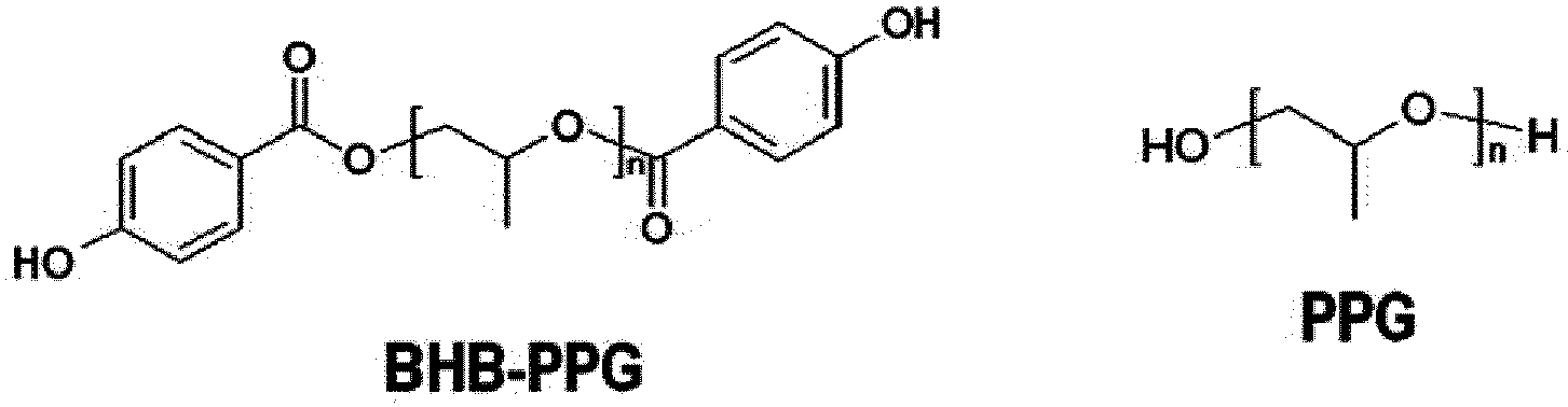
- By using the polymer sample prepared in Preparation Example 1, MALDI spectra were measured for six spots of each of two specimens prepared by the Dried droplet method (MALDI-TOF MS equipment: UltrafleXtreme, Bruker Daltonics, Germany).
- By using the polymer sample prepared in Preparation Example 1 and the
electrospray apparatus 10 as shown inFig. 4e and themask 200 as shown inFig. 4d , MALDI spectra were measured for six spots of each of two specimens prepared as inFig. 5 . - The MALDI-TOF spectra of the specimens prepared in Comparative Example 1 and Example 1 are shown in
Fig. 6 . As shown inFig. 6 , the reproducibility of spectrum is higher in the specimen of Example 1 manufactured using the electrospray and the mask. - The specimens were prepared in the same manner as in Example 1, using the polymer samples having the BHB-PPG and PPG concentrations of 0.5(mg/mL)/0.5(mg/mL), 1.0(mg/mL)/0.5(mg/mL) and 3.0(mg/mL)/0.5(mg/mL), respectively.
- To attain MALDI spectrum, a specimen is generally prepared by electrospray of a polymer sample on a stainless steel plate at a flow rate (1st flow) of 0.5 µL/min for 10 minutes. However, the stainless steel plate has a rough surface and thus it is not suitable for measuring thickness of specimen. Therefore, in the case of measuring the thickness of the electrosprayed specimen, the polymer sample is electrosprayed onto an ITO glass at a flow rate (1st flow) of 0.5 µL/min for 10 minutes, and then the thickness of the specimen was measured at 2 µm intervals using an optical profiler. The average thickness for the measured thickness profile was about 1 µm. Assuming that the spot size of the MALDI laser is 50 µm, the standard deviation of the average of the 25 measured values was measured and as a result, the thickness deviation was about 25%.
- For each specimen, MALDI-TOF spectra were measured three times or more at three different points. The measurement results are shown in
Fig. 7 . - According to the results of
Fig. 7 , the specimens prepared by the method according to the present invention has an error range within 15% of the spectrum measured at different points in the same specimen, and an error range of at least 5%. Therefore, highly reproducible MALDI spectral results can be attained. - Three specimens were prepared for each concentration in the same manner as in Example 1, using the polymer samples having BHB-PPG and PPG concentrations of 0.5(mg/mL)/0.5(mg/mL), 1.0(mg/mL)/0.5(mg/mL) and 3.0(mg/mL)/0.5(mg/mL), respectively.
- To attain MALDI spectrum, a specimen is generally prepared by electrospray of a polymer sample on a stainless steel plate at a flow rate (1st flow) of 0.5 µL/min for 10 minutes. However, the stainless steel plate is a rough surface and thus it is not suitable for measuring thickness of specimen. Therefore, in the case of measuring the thickness of the electrosprayed specimen, the polymer sample is electrosprayed onto an ITO glass at a flow rate (1st flow) of 0.5 µL/min for 10 minutes, and then the thickness of the specimen was measured at 2 µm intervals using an optical profiler. The average thickness for the measured thickness profile was about 1 µm. Assuming that the spot size of the MALDI laser is 50 µm, the standard deviation of the average of the 25 measured values was measured and as a result, the thickness deviation was about 25%.
- The reproducibility was evaluated by MALDI-TOF measurement on three specimens having the same concentration condition, respectively, and the result is shown in
Fig 8 . - According to the results as shown in
Fig. 8 , the specimens prepared by the method according to the present invention exhibit an error range within 30% of the MALDI spectrum for the specimens prepared under the same condition. Therefore, if the specimens are manufactured under the same condition, a reproducible MALDI spectrum can be attained. - While the present invention has been particularly shown and described with reference to specific embodiments thereof, it will be apparent to those skilled in the art that this specific description is merely a preferred embodiment and that the scope of the invention is not limited thereby. It is therefore intended that the scope of the invention be defined by the claims appended hereto and their equivalents.
[Description of Symbols] 10: Electrospray apparatus 100: Nozzle unit 110: Main nozzle 120: Auxiliary nozzle 130: Sheath gas supply pipe 200: Mask 200a: Hole 210: Sample stage 300: Unit for adjusting mask position 310: Mask holder 310a: Opening 310b: Convex portion 320: Linear motion rail 320a: Mounting portion 320b: Rail portion 330: Spacer 340: Fixing portion 20: Main body 30: Unit for adjusting injection amount of sample 40: Unit for adjusting sheath gas
Claims (12)
- A method for quantitative analysis of a polymer using MALDI mass spectrometry with a specimen prepared by electrospray of a polymer sample, which is a mixed solution of a polymer compound, a matrix and a solvent, from a main nozzle onto a sample plate through a mask, wherein a thickness deviation in the specimen is 30% or less, and the mask comprises a hole through which the polymer sample to be electrosprayed can be passed to the sample plate.
- The method for quantitative analysis of a polymer using MALDI mass spectrometry according to claim 1, wherein the error range of measurement results of the MALDI spectrum on the specimen (a relative standard deviation (RSD) of results of three experiments) is within 30%.
- The method for quantitative analysis of a polymer using MALDI mass spectrometry according to claim 1, wherein the error range of measurement results of the MALDI spectrum on at least three specimens prepared under the same condition is within 30%.
- The method for quantitative analysis of a polymer using MALDI mass spectrometry according to claim 1, wherein the method is for measuring a polymer having a molecular weight of 1000 Da or more.
- A method for preparing a specimen for MALDI mass spectrometry for quantitative analysis of a polymer, using an electrospray apparatus comprising a main nozzle for electrospray of a polymer sample which is a mixed solution of a polymer compound, a matrix and a solvent, and a sample plate on which the specimen is placed by electrospray of the polymer sample, the method comprising the steps of:mounting a mask on the sample plate;performing electrospray of the polymer sample from the main nozzle onto the sample plate provided with the mask; andobtaining the specimen of the polymer compound on the sample plate,wherein the mask comprises a hole through which the polymer sample to be electrosprayed from the main nozzle can be passed to the sample plate so as to obtain a uniform specimen having a small thickness deviation on the sample plate.
- The method for preparing a specimen for MALDI mass spectrometry for quantitative analysis of a polymer according to claim 5, wherein the hole has a diameter of 1 µm to 2 µm.
- The method for preparing a specimen for MALDI mass spectrometry for quantitative analysis of a polymer according to claim 5, wherein the mask is made of stainless steel or aluminum.
- The method for preparing a specimen for MALDI mass spectrometry for quantitative analysis of a polymer according to claim 5, wherein the step of mounting the mask on the sample plate further comprises adjusting the position of the mask in at least one of x-axis, y-axis, and z-axis directions.
- The method for preparing a specimen for MALDI mass spectrometry for quantitative analysis of a polymer according to claim 5, wherein the electrospray apparatus further comprises an auxiliary nozzle surrounding the main nozzle and coaxial with the main nozzle, and the step of electrospraying the polymer sample from the main nozzle onto the sample plate further comprises spraying the solvent with the auxiliary nozzle to prevent the matrix from being deposited in the vicinity of the main nozzle.
- The method for preparing a specimen for MALDI mass spectrometry for quantitative analysis of a polymer according to claim 5, wherein the electrospray apparatus further comprises a sheath gas supply pipe surrounding the auxiliary nozzle and coaxial with the auxiliary nozzle, and the step of electrospraying the polymer sample from the main nozzle onto the sample plate further comprises jetting a sheath gas through the sheath gas supply pipe so that the sheath gas guides the polymer sample to be sprayed onto the predetermined position of the sample plate.
- A method for preparing a specimen for MALDI mass spectrometry for quantitative analysis of a polymer, using an electrospray apparatus comprising a main nozzle for electrospray of a polymer sample which is a mixed solution of a polymer compound, a matrix and a solvent, and a sample plate on which the specimen is placed by electrospray of the polymer sample, the method comprising the steps of:performing electrospray of the polymer sample from the main nozzle onto the sample plate; andobtaining a specimen of the polymer sample on the sample plate,wherein the step of electrospraying the polymer sample from the main nozzle onto the sample plate further comprises at least one steps of (i) spraying the solvent from an auxiliary nozzle surrounding the main nozzle and coaxial with the main nozzle, so as to prevent the matrix from being deposited in the vicinity of the main nozzle, and (ii) jetting a sheath gas through a sheath gas supply pipe so that the sheath gas guides the polymer sample to be sprayed onto the predetermined position of the sample plate, so as to obtain a specimen having a thickness deviation of 30% or less.
- The method for preparing a specimen for MALDI mass spectrometry for quantitative analysis of a polymer according to any one of claims 5 to 11, wherein the jetting area through electrospray is 80 mm2 or less.
Applications Claiming Priority (2)
| Application Number | Priority Date | Filing Date | Title |
|---|---|---|---|
| KR1020170130010A KR102180624B1 (en) | 2017-10-11 | 2017-10-11 | Method for quantitative analysis of polymer using maldi mass spectrometry and method of manufacturing a sample for quantitative analysis of polymer using maldi mass spectrometry |
| PCT/KR2018/010591 WO2019074212A1 (en) | 2017-10-11 | 2018-09-11 | Method for quantitative analysis of polymer using maldi mass spectrometry, and method for manufacturing sample for maldi mass spectrometry for quantitative analysis of polymer |
Publications (3)
| Publication Number | Publication Date |
|---|---|
| EP3696529A1 true EP3696529A1 (en) | 2020-08-19 |
| EP3696529A4 EP3696529A4 (en) | 2021-01-06 |
| EP3696529B1 EP3696529B1 (en) | 2023-02-22 |
Family
ID=66101443
Family Applications (1)
| Application Number | Title | Priority Date | Filing Date |
|---|---|---|---|
| EP18867231.5A Active EP3696529B1 (en) | 2017-10-11 | 2018-09-11 | Method for quantitative analysis of polymer using maldi mass spectrometry, and method for manufacturing sample for maldi mass spectrometry for quantitative analysis of polymer |
Country Status (6)
| Country | Link |
|---|---|
| US (1) | US10991559B2 (en) |
| EP (1) | EP3696529B1 (en) |
| JP (1) | JP7160242B2 (en) |
| KR (1) | KR102180624B1 (en) |
| CN (1) | CN110612441A (en) |
| WO (1) | WO2019074212A1 (en) |
Families Citing this family (3)
| Publication number | Priority date | Publication date | Assignee | Title |
|---|---|---|---|---|
| WO2020045821A1 (en) * | 2018-08-30 | 2020-03-05 | 주식회사 엘지화학 | Method for relative quantitative analysis of polymer using maldi mass spectrometry |
| KR102362175B1 (en) | 2018-08-30 | 2022-02-11 | 주식회사 엘지화학 | Method for relative quantitatification of polymers using maldi spectrtrometry |
| KR102362170B1 (en) | 2019-04-08 | 2022-02-11 | 주식회사 엘지화학 | Method for relative quantitatification of polymers using maldi mass spectrometry |
Family Cites Families (32)
| Publication number | Priority date | Publication date | Assignee | Title |
|---|---|---|---|---|
| GB2235528B (en) * | 1989-08-23 | 1993-07-28 | Finnigan Mat Ltd | Method of preparing samples for laser spectrometry analysis |
| US6918309B2 (en) * | 2001-01-17 | 2005-07-19 | Irm Llc | Sample deposition method and system |
| WO2003040715A1 (en) | 2001-11-05 | 2003-05-15 | Irm, Llc. | Sample preparation methods for maldi mass spectrometry |
| CA2502413A1 (en) | 2002-11-01 | 2004-05-21 | The Regents Of The University Of Colorado, A Body Corporate | Quantitative analysis of protein isoforms using matrix-assisted laser desorption/ionization time of flight mass spectrometry |
| US7858387B2 (en) * | 2003-04-30 | 2010-12-28 | Perkinelmer Health Sciences, Inc. | Method of scanning a sample plate surface mask in an area adjacent to a conductive area using matrix-assisted laser desorption and ionization mass spectrometry |
| US6891156B2 (en) | 2003-04-30 | 2005-05-10 | Perkin Elmer Instruments Llc | Sample plate for matrix-assisted laser desorption and ionization mass spectrometry |
| KR100534204B1 (en) | 2004-03-17 | 2005-12-07 | 한국과학기술연구원 | Nanowire assisted laser desorption/ionization mass spectrometric analysis |
| CN101073137A (en) * | 2004-03-30 | 2007-11-14 | 普渡研究基金会 | Method and system for desorption electrospray ionization |
| GB0409118D0 (en) | 2004-04-26 | 2004-05-26 | Micromass Ltd | Mass spectrometer |
| DE102004044196B4 (en) * | 2004-09-14 | 2019-03-07 | Bruker Daltonik Gmbh | Mass spectrometer with a laser system for the ionization of a sample by matrix-assisted laser desorption in mass spectrometric analysis |
| US7095018B2 (en) * | 2004-12-29 | 2006-08-22 | Wisconsin Alumni Research Foundation | Deposition of samples and sample matrix for enhancing the sensitivity of matrix assisted laser desorption/ionization mass spectrometry |
| CN101175546A (en) * | 2005-04-05 | 2008-05-07 | 蛋白质发现公司 | Improved analyte enrichment and fractionation methods and devices for use in chemical analysis including matrix-assisted laser desorption ionization mass spectrometry |
| EP2022076A2 (en) | 2006-05-02 | 2009-02-11 | Centre National De La Recherche Scientifique (Cnrs) | Masks useful for maldi imaging of tissue sections, processes of manufacture and uses thereof |
| JP4732951B2 (en) | 2006-05-22 | 2011-07-27 | 株式会社島津製作所 | Sample preparation method and mass spectrometry method for MALDI |
| US20100176287A1 (en) * | 2006-11-23 | 2010-07-15 | Koninklijke Philips Electronics N.V. | Device for separation and maldi analysis of an analyte in a sample |
| GB0709517D0 (en) | 2007-05-17 | 2007-06-27 | Queen Mary & Westfield College | An electrostatic spraying device and a method of electrostatic spraying |
| JP5365547B2 (en) | 2010-02-25 | 2013-12-11 | 株式会社島津製作所 | Sample preparation method for MALDI-MS |
| WO2011150070A2 (en) * | 2010-05-25 | 2011-12-01 | Drexel University | System and method for controlled electrospray deposition |
| JP2012230801A (en) | 2011-04-26 | 2012-11-22 | Shimadzu Corp | Maldi mass spectrometry device |
| CN102519779B (en) | 2011-12-06 | 2013-06-12 | 吉林大学 | Concentration and demineralization purification treatment method of biological samples |
| JP6086343B2 (en) | 2012-10-01 | 2017-03-01 | 三菱レイヨン株式会社 | Method for measuring molecular weight of polymer, method for producing polymer, method for producing resist composition, and method for producing substrate on which pattern is formed |
| KR101434092B1 (en) * | 2013-03-08 | 2014-08-26 | 성균관대학교산학협력단 | Apparatus for forming patterns |
| WO2014162557A1 (en) | 2013-04-04 | 2014-10-09 | 株式会社島津製作所 | Maldi sample preparation method and sample preparation device |
| JP6183779B2 (en) | 2013-04-10 | 2017-08-23 | 株式会社島津製作所 | Sample preparation method and mass spectrometry method for mass spectrometry |
| JP2016032780A (en) | 2014-07-31 | 2016-03-10 | 東レエンジニアリング株式会社 | Electrospray device |
| CZ305831B6 (en) * | 2014-09-16 | 2016-03-30 | Petr Novák | Method of modifying surfaces with proteins for pre-concentration of analyte for desorption-ionizing techniques of mass spectrometry and immunochemical assays |
| JP6264275B2 (en) * | 2014-12-12 | 2018-01-24 | 株式会社島津製作所 | Matrix film forming equipment |
| JP6774619B2 (en) | 2015-03-31 | 2020-10-28 | 日油株式会社 | Matrix-assisted laser desorption mass spectrometry for high molecular weight polyoxyethylene derivatives |
| JP6498497B2 (en) | 2015-04-01 | 2019-04-10 | 学校法人慶應義塾 | Method of creating spray device for sheathless CE-MS, spray device for sheathless CE-MS, and sheathless CE-MS device |
| KR101746535B1 (en) | 2015-07-27 | 2017-06-13 | 서강대학교산학협력단 | Quantitative Analysis for Oligomers in Polymer using MALDI-TOF Mass analysis |
| KR101752656B1 (en) | 2015-08-17 | 2017-07-03 | 연세대학교 산학협력단 | Sample plate using MALDI-TOF mass spectrometer and manufacturing method of the sample plate |
| KR102457130B1 (en) | 2016-05-17 | 2022-10-24 | 삼성전자주식회사 | Semiconductor device and method for manufacturing the same |
-
2017
- 2017-10-11 KR KR1020170130010A patent/KR102180624B1/en active Active
-
2018
- 2018-09-11 CN CN201880030391.8A patent/CN110612441A/en active Pending
- 2018-09-11 US US16/624,383 patent/US10991559B2/en active Active
- 2018-09-11 JP JP2019561763A patent/JP7160242B2/en active Active
- 2018-09-11 EP EP18867231.5A patent/EP3696529B1/en active Active
- 2018-09-11 WO PCT/KR2018/010591 patent/WO2019074212A1/en not_active Ceased
Also Published As
| Publication number | Publication date |
|---|---|
| WO2019074212A9 (en) | 2019-06-06 |
| KR102180624B1 (en) | 2020-11-18 |
| CN110612441A (en) | 2019-12-24 |
| JP2020520452A (en) | 2020-07-09 |
| US20200219709A1 (en) | 2020-07-09 |
| WO2019074212A1 (en) | 2019-04-18 |
| EP3696529A4 (en) | 2021-01-06 |
| JP7160242B2 (en) | 2022-10-25 |
| US10991559B2 (en) | 2021-04-27 |
| KR20190040652A (en) | 2019-04-19 |
| EP3696529B1 (en) | 2023-02-22 |
Similar Documents
| Publication | Publication Date | Title |
|---|---|---|
| US8207494B2 (en) | Laser ablation flowing atmospheric-pressure afterglow for ambient mass spectrometry | |
| CA2440833C (en) | Piezoelectric charged droplet source | |
| EP2297769B1 (en) | Single and multiple operating mode ion sources with atmospheric pressure chemical ionization | |
| US6649907B2 (en) | Charge reduction electrospray ionization ion source | |
| JP6264275B2 (en) | Matrix film forming equipment | |
| CA2299439C (en) | Multiple sample introduction mass spectrometry | |
| EP3696529B1 (en) | Method for quantitative analysis of polymer using maldi mass spectrometry, and method for manufacturing sample for maldi mass spectrometry for quantitative analysis of polymer | |
| US7189977B2 (en) | Electrospray mass spectrometer and ion source | |
| Murray et al. | Aerosol matrix-assisted laser desorption ionization mass spectrometry | |
| DE60133548T2 (en) | A NORMAL PRESSURE LENS GENERATING A LARGER AND STABILIZED ION FLOW | |
| KR102121644B1 (en) | Method for comparative quantitative analysis of polymers using maldi mass spectrometry | |
| KR102362170B1 (en) | Method for relative quantitatification of polymers using maldi mass spectrometry | |
| DE102018010092B4 (en) | Ion supply system and method for controlling an ion supply system | |
| US10081026B2 (en) | Spraying system and methods of use thereof | |
| EP3702778B1 (en) | Method for relative quantitative analysis of polymer using maldi mass spectrometry | |
| DE112015000990T5 (en) | Impactor spray atmospheric pressure ion source with a target paddle | |
| JP4576609B2 (en) | Laser ionization mass spectrometry method and laser ionization mass spectrometer | |
| EP2669929A1 (en) | High-performance ion source and method for generating an ion beam | |
| DE19963317A1 (en) | Process for ionizing analysis materials on the tips of micro dendrites under the influence of a high electric field, comprises feeding the materials to the tips of the dendrites | |
| WO2011150070A2 (en) | System and method for controlled electrospray deposition | |
| de VRIES et al. | and H. RUSSEL WENDT |
Legal Events
| Date | Code | Title | Description |
|---|---|---|---|
| STAA | Information on the status of an ep patent application or granted ep patent |
Free format text: STATUS: THE INTERNATIONAL PUBLICATION HAS BEEN MADE |
|
| PUAI | Public reference made under article 153(3) epc to a published international application that has entered the european phase |
Free format text: ORIGINAL CODE: 0009012 |
|
| STAA | Information on the status of an ep patent application or granted ep patent |
Free format text: STATUS: REQUEST FOR EXAMINATION WAS MADE |
|
| 17P | Request for examination filed |
Effective date: 20191106 |
|
| AK | Designated contracting states |
Kind code of ref document: A1 Designated state(s): AL AT BE BG CH CY CZ DE DK EE ES FI FR GB GR HR HU IE IS IT LI LT LU LV MC MK MT NL NO PL PT RO RS SE SI SK SM TR |
|
| AX | Request for extension of the european patent |
Extension state: BA ME |
|
| A4 | Supplementary search report drawn up and despatched |
Effective date: 20201203 |
|
| RIC1 | Information provided on ipc code assigned before grant |
Ipc: H01J 49/16 20060101ALI20201127BHEP Ipc: G01N 27/62 20060101ALI20201127BHEP Ipc: G01N 1/31 20060101ALI20201127BHEP Ipc: G01N 33/44 20060101ALI20201127BHEP Ipc: G01N 1/28 20060101AFI20201127BHEP Ipc: H01J 49/04 20060101ALI20201127BHEP |
|
| DAV | Request for validation of the european patent (deleted) | ||
| DAX | Request for extension of the european patent (deleted) | ||
| REG | Reference to a national code |
Ref country code: DE Ref legal event code: R079 Ref document number: 602018046533 Country of ref document: DE Free format text: PREVIOUS MAIN CLASS: G01N0001280000 Ipc: G01N0027626000 |
|
| GRAP | Despatch of communication of intention to grant a patent |
Free format text: ORIGINAL CODE: EPIDOSNIGR1 |
|
| STAA | Information on the status of an ep patent application or granted ep patent |
Free format text: STATUS: GRANT OF PATENT IS INTENDED |
|
| RIC1 | Information provided on ipc code assigned before grant |
Ipc: G01N 1/31 20060101ALI20220923BHEP Ipc: G01N 1/28 20060101ALI20220923BHEP Ipc: H01J 49/04 20060101ALI20220923BHEP Ipc: G01N 33/44 20060101ALI20220923BHEP Ipc: G01N 27/626 20210101AFI20220923BHEP |
|
| INTG | Intention to grant announced |
Effective date: 20221017 |
|
| GRAS | Grant fee paid |
Free format text: ORIGINAL CODE: EPIDOSNIGR3 |
|
| GRAA | (expected) grant |
Free format text: ORIGINAL CODE: 0009210 |
|
| STAA | Information on the status of an ep patent application or granted ep patent |
Free format text: STATUS: THE PATENT HAS BEEN GRANTED |
|
| AK | Designated contracting states |
Kind code of ref document: B1 Designated state(s): AL AT BE BG CH CY CZ DE DK EE ES FI FR GB GR HR HU IE IS IT LI LT LU LV MC MK MT NL NO PL PT RO RS SE SI SK SM TR |
|
| REG | Reference to a national code |
Ref country code: GB Ref legal event code: FG4D |
|
| REG | Reference to a national code |
Ref country code: CH Ref legal event code: EP |
|
| REG | Reference to a national code |
Ref country code: AT Ref legal event code: REF Ref document number: 1549833 Country of ref document: AT Kind code of ref document: T Effective date: 20230315 Ref country code: IE Ref legal event code: FG4D |
|
| REG | Reference to a national code |
Ref country code: DE Ref legal event code: R096 Ref document number: 602018046533 Country of ref document: DE |
|
| REG | Reference to a national code |
Ref country code: LT Ref legal event code: MG9D |
|
| REG | Reference to a national code |
Ref country code: NL Ref legal event code: MP Effective date: 20230222 |
|
| REG | Reference to a national code |
Ref country code: AT Ref legal event code: MK05 Ref document number: 1549833 Country of ref document: AT Kind code of ref document: T Effective date: 20230222 |
|
| PG25 | Lapsed in a contracting state [announced via postgrant information from national office to epo] |
Ref country code: RS Free format text: LAPSE BECAUSE OF FAILURE TO SUBMIT A TRANSLATION OF THE DESCRIPTION OR TO PAY THE FEE WITHIN THE PRESCRIBED TIME-LIMIT Effective date: 20230222 Ref country code: PT Free format text: LAPSE BECAUSE OF FAILURE TO SUBMIT A TRANSLATION OF THE DESCRIPTION OR TO PAY THE FEE WITHIN THE PRESCRIBED TIME-LIMIT Effective date: 20230622 Ref country code: NO Free format text: LAPSE BECAUSE OF FAILURE TO SUBMIT A TRANSLATION OF THE DESCRIPTION OR TO PAY THE FEE WITHIN THE PRESCRIBED TIME-LIMIT Effective date: 20230522 Ref country code: NL Free format text: LAPSE BECAUSE OF FAILURE TO SUBMIT A TRANSLATION OF THE DESCRIPTION OR TO PAY THE FEE WITHIN THE PRESCRIBED TIME-LIMIT Effective date: 20230222 Ref country code: LV Free format text: LAPSE BECAUSE OF FAILURE TO SUBMIT A TRANSLATION OF THE DESCRIPTION OR TO PAY THE FEE WITHIN THE PRESCRIBED TIME-LIMIT Effective date: 20230222 Ref country code: LT Free format text: LAPSE BECAUSE OF FAILURE TO SUBMIT A TRANSLATION OF THE DESCRIPTION OR TO PAY THE FEE WITHIN THE PRESCRIBED TIME-LIMIT Effective date: 20230222 Ref country code: HR Free format text: LAPSE BECAUSE OF FAILURE TO SUBMIT A TRANSLATION OF THE DESCRIPTION OR TO PAY THE FEE WITHIN THE PRESCRIBED TIME-LIMIT Effective date: 20230222 Ref country code: ES Free format text: LAPSE BECAUSE OF FAILURE TO SUBMIT A TRANSLATION OF THE DESCRIPTION OR TO PAY THE FEE WITHIN THE PRESCRIBED TIME-LIMIT Effective date: 20230222 Ref country code: AT Free format text: LAPSE BECAUSE OF FAILURE TO SUBMIT A TRANSLATION OF THE DESCRIPTION OR TO PAY THE FEE WITHIN THE PRESCRIBED TIME-LIMIT Effective date: 20230222 |
|
| PG25 | Lapsed in a contracting state [announced via postgrant information from national office to epo] |
Ref country code: SE Free format text: LAPSE BECAUSE OF FAILURE TO SUBMIT A TRANSLATION OF THE DESCRIPTION OR TO PAY THE FEE WITHIN THE PRESCRIBED TIME-LIMIT Effective date: 20230222 Ref country code: PL Free format text: LAPSE BECAUSE OF FAILURE TO SUBMIT A TRANSLATION OF THE DESCRIPTION OR TO PAY THE FEE WITHIN THE PRESCRIBED TIME-LIMIT Effective date: 20230222 Ref country code: IS Free format text: LAPSE BECAUSE OF FAILURE TO SUBMIT A TRANSLATION OF THE DESCRIPTION OR TO PAY THE FEE WITHIN THE PRESCRIBED TIME-LIMIT Effective date: 20230622 Ref country code: GR Free format text: LAPSE BECAUSE OF FAILURE TO SUBMIT A TRANSLATION OF THE DESCRIPTION OR TO PAY THE FEE WITHIN THE PRESCRIBED TIME-LIMIT Effective date: 20230523 Ref country code: FI Free format text: LAPSE BECAUSE OF FAILURE TO SUBMIT A TRANSLATION OF THE DESCRIPTION OR TO PAY THE FEE WITHIN THE PRESCRIBED TIME-LIMIT Effective date: 20230222 |
|
| PG25 | Lapsed in a contracting state [announced via postgrant information from national office to epo] |
Ref country code: SM Free format text: LAPSE BECAUSE OF FAILURE TO SUBMIT A TRANSLATION OF THE DESCRIPTION OR TO PAY THE FEE WITHIN THE PRESCRIBED TIME-LIMIT Effective date: 20230222 Ref country code: RO Free format text: LAPSE BECAUSE OF FAILURE TO SUBMIT A TRANSLATION OF THE DESCRIPTION OR TO PAY THE FEE WITHIN THE PRESCRIBED TIME-LIMIT Effective date: 20230222 Ref country code: EE Free format text: LAPSE BECAUSE OF FAILURE TO SUBMIT A TRANSLATION OF THE DESCRIPTION OR TO PAY THE FEE WITHIN THE PRESCRIBED TIME-LIMIT Effective date: 20230222 Ref country code: DK Free format text: LAPSE BECAUSE OF FAILURE TO SUBMIT A TRANSLATION OF THE DESCRIPTION OR TO PAY THE FEE WITHIN THE PRESCRIBED TIME-LIMIT Effective date: 20230222 Ref country code: CZ Free format text: LAPSE BECAUSE OF FAILURE TO SUBMIT A TRANSLATION OF THE DESCRIPTION OR TO PAY THE FEE WITHIN THE PRESCRIBED TIME-LIMIT Effective date: 20230222 |
|
| REG | Reference to a national code |
Ref country code: DE Ref legal event code: R097 Ref document number: 602018046533 Country of ref document: DE |
|
| PG25 | Lapsed in a contracting state [announced via postgrant information from national office to epo] |
Ref country code: SK Free format text: LAPSE BECAUSE OF FAILURE TO SUBMIT A TRANSLATION OF THE DESCRIPTION OR TO PAY THE FEE WITHIN THE PRESCRIBED TIME-LIMIT Effective date: 20230222 |
|
| PLBE | No opposition filed within time limit |
Free format text: ORIGINAL CODE: 0009261 |
|
| STAA | Information on the status of an ep patent application or granted ep patent |
Free format text: STATUS: NO OPPOSITION FILED WITHIN TIME LIMIT |
|
| 26N | No opposition filed |
Effective date: 20231123 |
|
| PG25 | Lapsed in a contracting state [announced via postgrant information from national office to epo] |
Ref country code: SI Free format text: LAPSE BECAUSE OF FAILURE TO SUBMIT A TRANSLATION OF THE DESCRIPTION OR TO PAY THE FEE WITHIN THE PRESCRIBED TIME-LIMIT Effective date: 20230222 |
|
| REG | Reference to a national code |
Ref country code: CH Ref legal event code: PL |
|
| PG25 | Lapsed in a contracting state [announced via postgrant information from national office to epo] |
Ref country code: LU Free format text: LAPSE BECAUSE OF NON-PAYMENT OF DUE FEES Effective date: 20230911 |
|
| REG | Reference to a national code |
Ref country code: BE Ref legal event code: MM Effective date: 20230930 |
|
| PG25 | Lapsed in a contracting state [announced via postgrant information from national office to epo] |
Ref country code: MC Free format text: LAPSE BECAUSE OF FAILURE TO SUBMIT A TRANSLATION OF THE DESCRIPTION OR TO PAY THE FEE WITHIN THE PRESCRIBED TIME-LIMIT Effective date: 20230222 Ref country code: LU Free format text: LAPSE BECAUSE OF NON-PAYMENT OF DUE FEES Effective date: 20230911 Ref country code: IT Free format text: LAPSE BECAUSE OF FAILURE TO SUBMIT A TRANSLATION OF THE DESCRIPTION OR TO PAY THE FEE WITHIN THE PRESCRIBED TIME-LIMIT Effective date: 20230222 |
|
| REG | Reference to a national code |
Ref country code: IE Ref legal event code: MM4A |
|
| PG25 | Lapsed in a contracting state [announced via postgrant information from national office to epo] |
Ref country code: IE Free format text: LAPSE BECAUSE OF NON-PAYMENT OF DUE FEES Effective date: 20230911 |
|
| PG25 | Lapsed in a contracting state [announced via postgrant information from national office to epo] |
Ref country code: CH Free format text: LAPSE BECAUSE OF NON-PAYMENT OF DUE FEES Effective date: 20230930 |
|
| PG25 | Lapsed in a contracting state [announced via postgrant information from national office to epo] |
Ref country code: IE Free format text: LAPSE BECAUSE OF NON-PAYMENT OF DUE FEES Effective date: 20230911 Ref country code: CH Free format text: LAPSE BECAUSE OF NON-PAYMENT OF DUE FEES Effective date: 20230930 |
|
| PG25 | Lapsed in a contracting state [announced via postgrant information from national office to epo] |
Ref country code: BE Free format text: LAPSE BECAUSE OF NON-PAYMENT OF DUE FEES Effective date: 20230930 |
|
| PG25 | Lapsed in a contracting state [announced via postgrant information from national office to epo] |
Ref country code: BG Free format text: LAPSE BECAUSE OF FAILURE TO SUBMIT A TRANSLATION OF THE DESCRIPTION OR TO PAY THE FEE WITHIN THE PRESCRIBED TIME-LIMIT Effective date: 20230222 |
|
| PG25 | Lapsed in a contracting state [announced via postgrant information from national office to epo] |
Ref country code: BG Free format text: LAPSE BECAUSE OF FAILURE TO SUBMIT A TRANSLATION OF THE DESCRIPTION OR TO PAY THE FEE WITHIN THE PRESCRIBED TIME-LIMIT Effective date: 20230222 |
|
| PG25 | Lapsed in a contracting state [announced via postgrant information from national office to epo] |
Ref country code: CY Free format text: LAPSE BECAUSE OF FAILURE TO SUBMIT A TRANSLATION OF THE DESCRIPTION OR TO PAY THE FEE WITHIN THE PRESCRIBED TIME-LIMIT; INVALID AB INITIO Effective date: 20180911 |
|
| PG25 | Lapsed in a contracting state [announced via postgrant information from national office to epo] |
Ref country code: HU Free format text: LAPSE BECAUSE OF FAILURE TO SUBMIT A TRANSLATION OF THE DESCRIPTION OR TO PAY THE FEE WITHIN THE PRESCRIBED TIME-LIMIT; INVALID AB INITIO Effective date: 20180911 |
|
| PGFP | Annual fee paid to national office [announced via postgrant information from national office to epo] |
Ref country code: DE Payment date: 20250820 Year of fee payment: 8 |
|
| PGFP | Annual fee paid to national office [announced via postgrant information from national office to epo] |
Ref country code: GB Payment date: 20250820 Year of fee payment: 8 |
|
| PGFP | Annual fee paid to national office [announced via postgrant information from national office to epo] |
Ref country code: FR Payment date: 20250821 Year of fee payment: 8 |
|
| PG25 | Lapsed in a contracting state [announced via postgrant information from national office to epo] |
Ref country code: TR Free format text: LAPSE BECAUSE OF FAILURE TO SUBMIT A TRANSLATION OF THE DESCRIPTION OR TO PAY THE FEE WITHIN THE PRESCRIBED TIME-LIMIT Effective date: 20230222 |