EP3696404B1 - Verfahren, vorrichtung und system zur bestimmung der abweichung des winkels zum wind und korrektur des winkels zum wind - Google Patents
Verfahren, vorrichtung und system zur bestimmung der abweichung des winkels zum wind und korrektur des winkels zum wind Download PDFInfo
- Publication number
- EP3696404B1 EP3696404B1 EP18908257.1A EP18908257A EP3696404B1 EP 3696404 B1 EP3696404 B1 EP 3696404B1 EP 18908257 A EP18908257 A EP 18908257A EP 3696404 B1 EP3696404 B1 EP 3696404B1
- Authority
- EP
- European Patent Office
- Prior art keywords
- section
- windspeed
- angle
- wind
- deviation
- Prior art date
- Legal status (The legal status is an assumption and is not a legal conclusion. Google has not performed a legal analysis and makes no representation as to the accuracy of the status listed.)
- Active
Links
Images


Classifications
-
- F—MECHANICAL ENGINEERING; LIGHTING; HEATING; WEAPONS; BLASTING
- F03—MACHINES OR ENGINES FOR LIQUIDS; WIND, SPRING, OR WEIGHT MOTORS; PRODUCING MECHANICAL POWER OR A REACTIVE PROPULSIVE THRUST, NOT OTHERWISE PROVIDED FOR
- F03D—WIND MOTORS
- F03D7/00—Controlling wind motors
- F03D7/02—Controlling wind motors the wind motors having rotation axis substantially parallel to the air flow entering the rotor
- F03D7/04—Automatic control; Regulation
- F03D7/042—Automatic control; Regulation by means of an electrical or electronic controller
-
- F—MECHANICAL ENGINEERING; LIGHTING; HEATING; WEAPONS; BLASTING
- F03—MACHINES OR ENGINES FOR LIQUIDS; WIND, SPRING, OR WEIGHT MOTORS; PRODUCING MECHANICAL POWER OR A REACTIVE PROPULSIVE THRUST, NOT OTHERWISE PROVIDED FOR
- F03D—WIND MOTORS
- F03D7/00—Controlling wind motors
- F03D7/02—Controlling wind motors the wind motors having rotation axis substantially parallel to the air flow entering the rotor
- F03D7/0204—Controlling wind motors the wind motors having rotation axis substantially parallel to the air flow entering the rotor for orientation in relation to wind direction
-
- F—MECHANICAL ENGINEERING; LIGHTING; HEATING; WEAPONS; BLASTING
- F03—MACHINES OR ENGINES FOR LIQUIDS; WIND, SPRING, OR WEIGHT MOTORS; PRODUCING MECHANICAL POWER OR A REACTIVE PROPULSIVE THRUST, NOT OTHERWISE PROVIDED FOR
- F03D—WIND MOTORS
- F03D17/00—Monitoring or testing of wind motors, e.g. diagnostics
-
- F—MECHANICAL ENGINEERING; LIGHTING; HEATING; WEAPONS; BLASTING
- F05—INDEXING SCHEMES RELATING TO ENGINES OR PUMPS IN VARIOUS SUBCLASSES OF CLASSES F01-F04
- F05B—INDEXING SCHEME RELATING TO WIND, SPRING, WEIGHT, INERTIA OR LIKE MOTORS, TO MACHINES OR ENGINES FOR LIQUIDS COVERED BY SUBCLASSES F03B, F03D AND F03G
- F05B2260/00—Function
- F05B2260/70—Adjusting of angle of incidence or attack of rotating blades
- F05B2260/74—Adjusting of angle of incidence or attack of rotating blades by turning around an axis perpendicular the rotor centre line
-
- F—MECHANICAL ENGINEERING; LIGHTING; HEATING; WEAPONS; BLASTING
- F05—INDEXING SCHEMES RELATING TO ENGINES OR PUMPS IN VARIOUS SUBCLASSES OF CLASSES F01-F04
- F05B—INDEXING SCHEME RELATING TO WIND, SPRING, WEIGHT, INERTIA OR LIKE MOTORS, TO MACHINES OR ENGINES FOR LIQUIDS COVERED BY SUBCLASSES F03B, F03D AND F03G
- F05B2260/00—Function
- F05B2260/83—Testing, e.g. methods, components or tools therefor
-
- F—MECHANICAL ENGINEERING; LIGHTING; HEATING; WEAPONS; BLASTING
- F05—INDEXING SCHEMES RELATING TO ENGINES OR PUMPS IN VARIOUS SUBCLASSES OF CLASSES F01-F04
- F05B—INDEXING SCHEME RELATING TO WIND, SPRING, WEIGHT, INERTIA OR LIKE MOTORS, TO MACHINES OR ENGINES FOR LIQUIDS COVERED BY SUBCLASSES F03B, F03D AND F03G
- F05B2270/00—Control
- F05B2270/10—Purpose of the control system
- F05B2270/103—Purpose of the control system to affect the output of the engine
- F05B2270/1033—Power (if explicitly mentioned)
-
- F—MECHANICAL ENGINEERING; LIGHTING; HEATING; WEAPONS; BLASTING
- F05—INDEXING SCHEMES RELATING TO ENGINES OR PUMPS IN VARIOUS SUBCLASSES OF CLASSES F01-F04
- F05B—INDEXING SCHEME RELATING TO WIND, SPRING, WEIGHT, INERTIA OR LIKE MOTORS, TO MACHINES OR ENGINES FOR LIQUIDS COVERED BY SUBCLASSES F03B, F03D AND F03G
- F05B2270/00—Control
- F05B2270/10—Purpose of the control system
- F05B2270/109—Purpose of the control system to prolong engine life
- F05B2270/1095—Purpose of the control system to prolong engine life by limiting mechanical stresses
-
- F—MECHANICAL ENGINEERING; LIGHTING; HEATING; WEAPONS; BLASTING
- F05—INDEXING SCHEMES RELATING TO ENGINES OR PUMPS IN VARIOUS SUBCLASSES OF CLASSES F01-F04
- F05B—INDEXING SCHEME RELATING TO WIND, SPRING, WEIGHT, INERTIA OR LIKE MOTORS, TO MACHINES OR ENGINES FOR LIQUIDS COVERED BY SUBCLASSES F03B, F03D AND F03G
- F05B2270/00—Control
- F05B2270/30—Control parameters, e.g. input parameters
- F05B2270/32—Wind speeds
-
- F—MECHANICAL ENGINEERING; LIGHTING; HEATING; WEAPONS; BLASTING
- F05—INDEXING SCHEMES RELATING TO ENGINES OR PUMPS IN VARIOUS SUBCLASSES OF CLASSES F01-F04
- F05B—INDEXING SCHEME RELATING TO WIND, SPRING, WEIGHT, INERTIA OR LIKE MOTORS, TO MACHINES OR ENGINES FOR LIQUIDS COVERED BY SUBCLASSES F03B, F03D AND F03G
- F05B2270/00—Control
- F05B2270/30—Control parameters, e.g. input parameters
- F05B2270/321—Wind directions
-
- F—MECHANICAL ENGINEERING; LIGHTING; HEATING; WEAPONS; BLASTING
- F05—INDEXING SCHEMES RELATING TO ENGINES OR PUMPS IN VARIOUS SUBCLASSES OF CLASSES F01-F04
- F05B—INDEXING SCHEME RELATING TO WIND, SPRING, WEIGHT, INERTIA OR LIKE MOTORS, TO MACHINES OR ENGINES FOR LIQUIDS COVERED BY SUBCLASSES F03B, F03D AND F03G
- F05B2270/00—Control
- F05B2270/30—Control parameters, e.g. input parameters
- F05B2270/329—Azimuth or yaw angle
-
- F—MECHANICAL ENGINEERING; LIGHTING; HEATING; WEAPONS; BLASTING
- F05—INDEXING SCHEMES RELATING TO ENGINES OR PUMPS IN VARIOUS SUBCLASSES OF CLASSES F01-F04
- F05B—INDEXING SCHEME RELATING TO WIND, SPRING, WEIGHT, INERTIA OR LIKE MOTORS, TO MACHINES OR ENGINES FOR LIQUIDS COVERED BY SUBCLASSES F03B, F03D AND F03G
- F05B2270/00—Control
- F05B2270/30—Control parameters, e.g. input parameters
- F05B2270/335—Output power or torque
-
- F—MECHANICAL ENGINEERING; LIGHTING; HEATING; WEAPONS; BLASTING
- F05—INDEXING SCHEMES RELATING TO ENGINES OR PUMPS IN VARIOUS SUBCLASSES OF CLASSES F01-F04
- F05B—INDEXING SCHEME RELATING TO WIND, SPRING, WEIGHT, INERTIA OR LIKE MOTORS, TO MACHINES OR ENGINES FOR LIQUIDS COVERED BY SUBCLASSES F03B, F03D AND F03G
- F05B2270/00—Control
- F05B2270/80—Devices generating input signals, e.g. transducers, sensors, cameras or strain gauges
- F05B2270/802—Calibration thereof
-
- Y—GENERAL TAGGING OF NEW TECHNOLOGICAL DEVELOPMENTS; GENERAL TAGGING OF CROSS-SECTIONAL TECHNOLOGIES SPANNING OVER SEVERAL SECTIONS OF THE IPC; TECHNICAL SUBJECTS COVERED BY FORMER USPC CROSS-REFERENCE ART COLLECTIONS [XRACs] AND DIGESTS
- Y02—TECHNOLOGIES OR APPLICATIONS FOR MITIGATION OR ADAPTATION AGAINST CLIMATE CHANGE
- Y02E—REDUCTION OF GREENHOUSE GAS [GHG] EMISSIONS, RELATED TO ENERGY GENERATION, TRANSMISSION OR DISTRIBUTION
- Y02E10/00—Energy generation through renewable energy sources
- Y02E10/70—Wind energy
- Y02E10/72—Wind turbines with rotation axis in wind direction
Definitions
- the present disclosure generally relates to the technical field of wind power generation, and in particular, to a method and an apparatus for determining a deviation in a wind alignment angle of a wind turbine, and a method and a system for correcting a wind alignment angle of a wind turbine.
- a horizontal axis design is usually adopted in a mainstream of wind turbines with power higher than a level of megawatts. It is necessary to provide the wind turbine with a yaw system in the horizontal axis design.
- a main function of the yaw system is keeping the wind turbine windward during power generation, and thereby it is necessary that the yaw system keeps tracking a wind direction.
- the yaw system generally detects a wind alignment angle (an angle between the wind direction and an axis of a nacelle) via a wind direction sensor (for example, a wind vane) installed at a top of the nacelle.
- An error between a wind alignment angle detected by the yaw system of the wind turbine and a real wind alignment angle is caused by an initial installation error, a failure due to long-term operation, and an influence of a wake of an impeller.
- the wind turbine cannot be kept windward based on a yaw angle that is determined from the wind alignment angle detected by the yaw system. Not only power generation of the wind turbine is reduced, but also a load imbalance of the wind turbine is exaggerated. Therefore, it is particularly important how to determine a deviation in the detected wind alignment angle easily and effectively.
- Patent document with publication No. US 2018/003153 A1 discloses a method for determining a calibration offset angle for a wind turbine, where the calibration offset angle corresponds to a maximum efficiency calculated based on a measured windspeed, and may be updated for each power bin when time lapses.
- Patent document with publication No. CN 105548614 A discloses a method for calibrating wind alignment angle, where the wind alignment angle corresponds to the maximum power is acquired for each windspeed section, and the wind speed and the acquire wind alignment angle are then fitted based on a polynomial equation.
- a method and an apparatus for determining a deviation in a wind alignment angle of a wind turbine, and a method and a system for correcting a wind alignment angle of a wind turbine are provided according to embodiments of the present disclosure, which are capable to determine a deviation in a detected wind alignment angle of a wind turbine easily and effectively, and correct a subsequently detected wind alignment angle based on the determined deviation; characterized in that: determining the deviation in the wind alignment angle for the windspeed section comprises: determining the deviation in the wind alignment angle for an i-th windspeed section, based on average power of each angle section corresponding to the i-th windspeed section, wherein the i-th windspeed section serves as the windspeed section; wherein average power P ij of a j-th angle section corresponding to the i-th windspeed section is an average of output power at all the moments at each of which the ambient wind speed belongs to the i-th windspeed section and the detected wind alignment belongs to the j-th angle section; and wherein a predetermined windspeed
- a method for determining a deviation in a wind alignment angle of a wind turbine including: obtaining history operation data of a wind turbine within a time period, where the history operation data includes ambient wind speeds, detected wind alignment angles, and output power that are at different moments in the time period; and determining the deviation in the wind alignment angle for a windspeed section, based on the detected wind alignment angle and the output power at a moment within in the time period, where the ambient wind speed at said moment belongs to the windspeed section.
- a method for correcting a wind alignment angle of a wind turbine including: obtaining a current ambient wind speed and a current detected wind alignment angle of a wind turbine; determining a windspeed section to which the current ambient wind speed belongs; and correcting the current detected wind alignment angle based on a deviation in the wind alignment angle for the determined windspeed section, to determine a yaw angle of the wind turbine based on the detected wind alignment angle that is corrected; where the deviation in the wind alignment angle for the determined windspeed section is obtained based on the aforementioned method for determining the deviation in the wind alignment angle of the wind turbine, and the determined windspeed section serves as the windspeed section in the aforementioned method.
- An apparatus for correcting a wind alignment angle of a wind turbine including: a history data obtaining unit, configured to obtain history operation data of a wind turbine within a time period, where the history operation data includes ambient wind speeds, detected wind alignment angles, and output power that are at different moments in the time period; and a deviation determination unit, configured to determine the deviation in the wind alignment angle for a windspeed section, based on the detected wind alignment angle and the output power at a moment within in the time period, where the ambient wind speed at said moment belongs to the windspeed section.
- a system for correcting a wind alignment angle of a wind turbine including: a data obtaining module, configured to obtaining a current ambient wind speed and a current detected wind alignment angle of a wind turbine; a windspeed section determination module, configured to determine a windspeed section to which the current ambient wind speed belongs; and the aforementioned apparatus for determining the deviation in the wind alignment angle; and a correction module, configured to correct the current detected wind alignment angle based on the deviation in the wind alignment angle for the determined windspeed section, to determine a yaw angle of the wind turbine based on the detected wind alignment angle that is corrected; where the deviation in the wind alignment angle is outputted from the apparatus, and the determined windspeed section serves as the windspeed section for the apparatus.
- a computer-readable storage medium storing a computer program is provided according to another embodiment of the present disclosure.
- the aforementioned method for determining the deviation in the wind alignment angle of the wind turbine is performed when the computer program is executed by a processor.
- a computing device is provided according to another exemplary embodiment of the present disclosure.
- the computing device includes a processor and a memory storing a computer program.
- the aforementioned method for determining the deviation in the wind alignment angle of the wind turbine is performed when the computer program is executed by the processor.
- a computer-readable storage medium storing a computer program is provided according to another embodiment of the present disclosure.
- the aforementioned method for correcting the wind alignment angle of the wind turbine is performed when the computer program is executed by a processor.
- a control system of a wind turbine is provided according to another embodiment of the present disclosure.
- the control system includes a processor and a memory storing a computer program.
- the aforementioned method for correcting the wind alignment angle of the wind turbine is performed when the computer program is executed by the processor.
- the method and the apparatus for determining the deviation in the wind alignment angle of the wind turbine, and the method and the system for correcting the wind alignment angle of the wind turbine are provided according to embodiments of the present disclosure.
- the deviation in the wind alignment angle can be determined for each windspeed section.
- the determined deviation can be used to correct a subsequently detected wind alignment angle, in a case that a corresponding ambient wind speed belongs to said windspeed section. Thereby, an effect of correcting the detected wind alignment angle is improved.
- the wind turbine can track a wind direction well through yaw control based on a yaw angle determined from the detected wind alignment angle that is corrected.
- Figure 2 is a flow chart of a method for determining a deviation in a wind alignment angle of a wind turbine according to an embodiment of the present disclosure.
- step S101 history operation data of a wind turbine within a time period is obtained.
- the history operation data includes ambient wind speeds, detected wind alignment angles, and output power that are at different moments (that is, sampling points) in the time period.
- adjacent sampling points may be spaced by a predetermined duration (that is, a sampling period may serve as the predetermined duration).
- the predetermined duration may be 10 minutes.
- the ambient wind speed is a wind speed of an environment in which the wind turbine is located.
- the detected wind alignment angle is a wind alignment angle that is detected by a hardware apparatus (for example, a wind direction sensor).
- the output power is power generated by the wind turbine.
- the time period may be a time period in which the wind turbine operates normally, which excludes a failure of the wind turbine, starting and halting of the wind turbine, and limited-power operation of the wind turbine.
- the history operation data of the wind turbine within the time period may be obtained from a supervisory control and data acquisition system (SCADA), or obtained from a main control system of the wind turbine.
- SCADA supervisory control and data acquisition system
- step S102 the deviation in the wind alignment angle is determined for each windspeed section based on the obtained history operation data.
- the deviation in the wind alignment angle is determined for a windspeed section, based on the detected wind alignment angle and the output power at a moment within the time period, where the ambient wind speed at said moment belongs to the windspeed section.
- the deviation in the wind alignment angle for each windspeed section may be used to correct a wind alignment angle that is subsequently detected, in a case that a subsequently acquired ambient wind speed belongs to the windspeed section.
- determining the deviation in the wind alignment angle for the windspeed section may include a following step.
- the deviation in the wind alignment angle is determined for an i-th windspeed section based on average power of each angle section corresponding to the i-th windspeed section, where the i-th windspeed section serves as the windspeed section.
- Average power P ij of a j-th angle section corresponding to the i-th windspeed section is an average of output power at all the moments, at each of which the ambient wind speed belongs to the i-th windspeed section and the detected wind alignment belongs to the j-th angle section.
- a predetermined windspeed range is divided into M windspeed sections, with a first predetermined interval.
- a predetermined angle range is divided into N angle sections, with a second predetermined interval, where i and j are integers, M ⁇ i > 0, and N ⁇ j > 0.
- the predetermined wind speed range may be determined based on wind speeds for starting and halting the wind turbine. For example, the predetermined wind speed range is from a wind speed for starting the wind turbine to a wind speed for halting the wind turbine.
- Figure 3 is a statistical graph of average power of each angle section corresponding to each windspeed section according to an embodiment of the present disclosure.
- an x-axis indicates a wind speed.
- the predetermined wind speed range is from 2.75m/s to 15.75m/s
- the first predetermined interval is 0.5m/s
- thereby the predetermined wind speed range is divided into 28 windspeed sections.
- a y-axis indicates an angle.
- the predetermined angle range is from -11° to 11°
- the second predetermined interval is 2°
- thereby the predetermined angle range is divided into 13 angle sections.
- a z-axis indicates average power.
- each windspeed section corresponds to N angle sections (N is equal to 13 in Figure 3 ).
- a value of z-axis coordinate of each angle section corresponding to each windspeed section is an average of output power at all the moments, at each of which the ambient wind speed belongs to said windspeed section and the detected wind alignment angle belongs to said angle section.
- two arrays A and B of a size M*N may be predefined.
- An element located in an i-th row and a j-th column in the array A stores cumulation of output power at all the moments, within the time period, at each of which the ambient wind speed belongs to the i-th windspeed section and the detected wind alignment angles belongs to the j-th angle section.
- An element located in an i-th row and a j-th column in the array B stores a quantity of all the moments, within the time period, at each of which the ambient wind speed belongs to the i-th windspeed section and the detected wind alignment angles belongs to the j-th angle section.
- P ij may be calculated based on the array A and the array B.
- a factor relevant to a sequence of the obtained history operation data is ignored, and thereby an amount of stored data can be effectively reduced. It is facilitated that the method for determining the deviation in the wind alignment angle of the wind turbine is implemented online.
- determining the deviation in the wind alignment angle for the windspeed section may include a following step.
- the deviation in the wind alignment angle for an i-th windspeed section is determined based on average power of all angle sections corresponding to the i-th windspeed section and power of the wind turbine facing windward for the i-th windspeed section.
- the power of the wind turbine facing windward for the i-th windspeed section is obtained based on the history operation data at all the moments, within the time period, at each of which the ambient wind speed belongs to the i-th windspeed section.
- ⁇ ij indicates the median of the j-th angle section corresponding to the i-th windspeed section, that is, the median of the j-th angle section.
- P i max indicates the power of the wind turbine facing windward for the i-th windspeed section, which is reflected by the history operation data at all the moments at each of which the ambient wind speed belongs to the i-th windspeed section.
- a series of data pairs of P ij and ⁇ ij (that is, ( P i 1 , ⁇ i 1 ), ( P i 2 , ⁇ i 2 ) , ( P i 3 , ⁇ i 3 ) , ...,( P i N , ⁇ i N )) are subject to curve-fitting (for example, fitted through a least square algorithm) based on equation (1), so as to obtain unknowns ⁇ i and P i max .
- a corresponding data pair ( P i a , ⁇ i a ) is not used for the fitting, in a case that there is no moment at which the ambient wind speed belongs to the i-th windspeed section and the detected wind alignment angle belongs to an a-th angle section (that is, there is no P i a ) .
- a corresponding data pair ( P i a , ⁇ i a ) may not be used for fitting, in a case that a quantity of all the moments, at each of which the ambient wind speed belongs to the i-th windspeed section and the detected wind alignment angle belongs to an a-th angle section, is less than a predetermined number.
- ⁇ ij in equation (1) may indicate alternatively an average of the detected wind alignment angles at all the moments, within the time period, at each of which the ambient wind speed belongs to the i-th windspeed section and the detected wind alignment angle belongs to the j-th angle section.
- determining the deviation in the wind alignment angle for the i-th windspeed section may include following steps.
- the deviation in the wind alignment angle is obtained for each pair of symmetrical angle sections corresponding to the i-th windspeed section.
- the deviation in the wind alignment angle for the i-th windspeed section is determined based on the obtained deviation in the wind alignment angle for each pair of symmetrical angle sections.
- the step of obtaining deviation in the wind alignment angle for each pair of symmetrical angle sections corresponding to the i-th windspeed section may be implemented as follows.
- the deviation in the wind alignment angle for a pair of symmetrical angle sections corresponding to the i-th windspeed section may be determined based on average power of both angle sections that are included in the pair of symmetrical angles corresponding to the i-th windspeed section.
- Each pair of symmetrical angle sections includes two angle sections that are symmetrical with respect to a reference angle section, and the reference angle section is one of the N angle sections.
- angle sections [-3°, -1°) and [1°, 3°) are a pair of symmetrical angle sections
- angle sections [-5°, -3°) and [3°, 5°) are a pair of symmetrical angle sections.
- the obtained deviations in the wind alignment angle for all the pairs of symmetrical angle sections corresponding to the i-th windspeed section may be averaged, to obtain the deviation in the wind alignment angle for the i-th windspeed section.
- the step of obtaining the deviation in the wind alignment angle for the pair of symmetrical angle sections corresponding to the i-th windspeed section may include a following step. For a k-th pair of symmetrical angle sections serving as the pair of symmetrical angle sections, average power P i (k1) and P i (k2) of angle sections k 1 and k 2 , respectively, corresponding to the i-th windspeed section are obtained.
- ⁇ i (k) in the wind alignment angle is calculated for the k-th pair of symmetrical angle sections corresponding to the i-th windspeed section based on equation (2) or equation (3):
- P i (ref) indicates average power of the reference angle section corresponding to the i-th windspeed section.
- d k is equal to a difference in a sequential number between the two angle sections k 1 and k 2 multiplying the second predetermined interval. For example, the difference in the sequential number between angle sections [-3°, -1°) and [1°, 3°) in a pair of symmetrical angle sections is 2, and the difference in the sequential number between angle sections [-5°, -3°) and [3°, 5°] in a pair of symmetrical angle sections is 4.
- P i (k 1 ) indicates an average of output power at all the moments at each of which the ambient wind speed belongs to the i-th windspeed section and the detected wind alignment angle belongs to the angle section k 1 .
- P i (k 2 ) indicates an average of output power at all the moments at each of which the ambient wind speed belongs to the i-th windspeed section and the detected wind alignment angle belongs to the angle section k 2 .
- P i (ref) indicates an average of output power at all the moments at each of which the ambient wind speed belongs to the i-th windspeed section and the detected wind alignment angle belongs to the reference angle section.
- ⁇ i (k) may be calculated only in a case that a difference between d k and an angle difference is less than a first preset threshold, where the angle difference is between the two angle sections k 1 and k 2 and calculated based on P i (k 1 ), P i (k 2 ) , and P i (ref) .
- ⁇ i (k) is not calculated for the k-th pair of symmetrical angle sections, in a case that the difference between d k and the angle difference is greater than or equal to the first preset threshold. Namely, there is no ⁇ i (k) in determining the deviation ⁇ i in the wind alignment angle for the i-th windspeed section.
- the deviation ⁇ i in the wind alignment angle may be calculated based on the history operation data of the k-th pair of symmetrical angle sections corresponding to the i-th windspeed section.
- the angle difference ⁇ i(k) between the two angle sections k 1 and k 2 , which are included in the k-th pair of symmetrical angle sections corresponding to the i-th windspeed section may be calculated based on equation (4).
- ⁇ i k cos ⁇ 1 P i k 1 1 3 + P i k 2 1 3 2 P i ref 1 3
- the deviation in the wind alignment angle can be easily and effectively calculated for each windspeed section according to the above embodiments.
- the deviation in the wind alignment angle may be determined for each windspeed section in other suitable manners, based on the detected wind alignment angle and the output power at the moment at which the ambient wind speed belongs to the windspeed section.
- Such manners are not limited in embodiments of the present disclosure.
- a maximum may be taken in one manner. Specifically, one or more largest output power are acquired among output power at all the moments at each of which the ambient wind speed belongs to the i-th windspeed section, and a detected wind alignment angle corresponding to the one or more largest output power is obtained. Medians of all angle sections to which the detected wind alignment angle belongs are averaged, to obtain the deviation in the wind alignment angle for the i-th windspeed section.
- the method for determining the deviation in the wind alignment angle of the wind turbine may further includes a following step.
- Abnormal data in the obtained history operation data is determined for each windspeed section, and the determined abnormal data is deleted.
- the step S102 is performed based on the history operation data from which the abnormal data is deleted.
- the step of determining abnormal data in the obtained history operation data for each windspeed section may be implemented as follows.
- the ambient wind speeds, the detected wind alignment angles, and the output power at all the moments, at each of which the ambient wind speed belongs to the i-th windspeed section and the detected wind alignment angles belongs to the j-th angle section are determined as the abnormal data for the i-th windspeed section, in a case that a quantity of all said moments is less than a second preset threshold, and/or in a case that a standard deviation of output power at all said moments is greater than a third preset threshold.
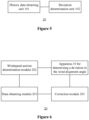
- Figure 4 is a flow chart of a method for correcting a wind alignment angle of a wind turbine according to an embodiment of the present disclosure.
- step S201 a current ambient wind speed and a current detected wind alignment angle of the wind turbine are obtained.
- step S202 a windspeed section to which the current ambient wind speed belongs is determined.
- step S203 the current detected wind alignment angle is corrected based on a deviation in the wind alignment angle for the determined windspeed section, so as to determine a yaw angle of the wind turbine based on the detected wind alignment angle that is corrected. Thereby, yaw control is performed based on the determined yaw angle.
- the deviation in the wind alignment angle for the determined windspeed section is obtained by a method for determining the deviation in the wind alignment angle of the wind turbine according to an embodiment as shown in Figure 2 .
- the method for correcting the wind alignment angle of the wind turbine may further include the steps S101 and S102 as shown in Figure 2 .
- the step of correcting the current detected wind alignment angle may include a followings step.
- the deviation in the wind alignment angle for the determined windspeed section is subtracted from the current detected wind alignment angle, to obtain the detected wind alignment angle that is corrected.
- the step of correcting the current detected wind alignment angle may include a followings step.
- the deviation in the wind alignment angle for the determined windspeed section, and a deviation in the wind alignment angle for at least one windspeed section adjacent to the determined windspeed section, are weighted to obtain a weighted deviation.
- the detected wind alignment angle that is corrected is obtained, by subtracting the weighted deviation from the current detected wind alignment angle.
- a weighting coefficient of the deviation in the wind alignment angle for each windspeed section in the weighting is determined based on a difference from the current ambient wind speed to a median of said windspeed section.
- the current ambient wind speed is 6.1m/s, belonging to a windspeed section [5.75, 6.25], and the detected wind alignment angle that is corrected may be obtained subtracting the deviation in the wind alignment angle for the windspeed section [5.75, 6.25] from the current detected wind alignment angle.
- the deviation in the wind alignment angle for the windspeed section [5.75, 6.25] and a deviation in the wind alignment angle for a windspeed section [6.25, 6.75] adjacent to the windspeed section [5.75, 6.25] may be weighted to obtain a weighted deviation.
- the weighting coefficients may be determined based on a distance from the current ambient wind speed 6.1m/s to a median value of the windspeed section [5.75, 6.25] and a distance from the current ambient wind speed 6.1m/s to a median value of the windspeed section [6.25, 6.75].
- the detected wind alignment angle that is corrected is obtained by subtracting the weighted deviation from the current detected wind alignment angle.
- the detected wind alignment angle may be corrected in other suitable manners, based on the deviation in the wind alignment angle corresponding to the windspeed section to which the current ambient wind speed belongs.
- Figure 5 is a block diagram of an apparatus for determining a deviation in a wind alignment angle of a wind turbine according to an embodiment of the present disclosure.
- the apparatus 10 for determining a deviation in a wind alignment angle of a wind turbine includes a history data obtaining unit 101 and a deviation determination unit 102, according to an embodiment of the present disclosure.
- the history data obtaining unit 101 is configured to obtain history operation data of a wind turbine within a time period, where the history operation data includes ambient wind speeds, detected wind alignment angles, and output power that are at different moments in the time period.
- the time period may be a time period in which the wind turbine operates normally, which excludes a failure of the wind turbine, starting and halting of the wind turbine, and limited-power operation of the wind turbine.
- the deviation determination unit 102 is configured to determine the deviation in the wind alignment angle for each windspeed section, based on the obtained history operation data.
- the deviation determination unit 102 determines the deviation in the wind alignment angle for a windspeed section based on the detected wind alignment angle and the output power at a moment within the time period, where the ambient wind speed at said moment belongs to the windspeed section.
- the deviation determination unit 102 may determine the deviation in the wind alignment angle for an i-th windspeed section, based on average power of each angle section corresponding to the i-th windspeed section.
- Average power P ij of a j-th angle section corresponding to the i-th windspeed section is an average of output power at all the moments at each of which the ambient wind speed belongs to the i-th windspeed section and the detected wind alignment belongs to the j-th angle section.
- a predetermined windspeed range is divided into M windspeed sections, with a first predetermined interval.
- a predetermined angle range is divided into N angle sections, with a second predetermined interval, where i and j are integers, M ⁇ i > 0, and N ⁇ j > 0.
- the deviation determination unit 102 may fit average power of the N angle sections corresponding to the i-th windspeed section and medians of the N angle sections based on equation (1), to obtain the deviation ⁇ i in the wind alignment angle for the i-th windspeed section and power P i max of the wind turbine facing windward for the i-th windspeed section.
- the deviation determination unit 102 may obtain the deviation in the wind alignment angle for each pair of symmetrical angle sections corresponding to the i-th windspeed section, and determine the deviation in the wind alignment angle for the i-th windspeed section, based on the obtained deviation in the wind alignment angle for each pair of symmetrical angle sections.
- the deviation determination unit 102 may determine the deviation in the wind alignment angle for a pair of symmetrical angle sections corresponding to the i-th windspeed section, based on average power of both angle sections that are included in the pair of symmetrical angles corresponding to the i-th windspeed section.
- Each pair of symmetrical angle sections include two angle sections that are symmetrical with respect to a reference angle section, and the reference angle section is one of the N angle sections.
- the deviation determination unit 102 may obtain average power P i (k 1 ) and P i (k 2 ) of angle sections k 1 and k 2 , respectively, corresponding to the i-th windspeed section, for a k-th pair of symmetrical angle sections serving as the pair of symmetrical angle sections.
- the deviation determination unit 102 may calculate the deviation ⁇ i (k) in the wind alignment angle for the k-th pair of symmetrical angle sections corresponding to the i-th windspeed section, based on equation (2) or equation (3).
- the deviation determination unit 102 may calculate ⁇ i (k) in a case that a difference between d k and an angle difference is less than a first preset threshold, where the angle difference is between the two angle sections k 1 and k 2 and calculated based on P i (k 1 ) , P i (k 2 ) , and P i (ref) ..
- the apparatus 10 for determining the deviation in the wind alignment angle of the wind turbine may further include an abnormal data deletion unit (not shown in figures).
- the abnormal data deletion unit is configured to determine abnormal data in the obtained history operation data for each windspeed section, and delete the determined abnormal data, such that the deviation determination unit 102 determines the deviation in the wind alignment angle for the windspeed section based on the history operation data from which abnormal data is deleted.
- the abnormal data deletion unit may determine the ambient wind speeds, the detected wind alignment angles, and the output power at all the moments, at each of which the ambient wind speed belongs to the i-th windspeed section and the detected wind alignment angles belongs to the j-th angle section, as the abnormal data for the i-th windspeed section, in a case that a quantity of all said moments is less than a second preset threshold, and/or in a case that a standard deviation of output power at all said moments is greater than a third preset threshold.
- the apparatus 10 for determining the deviation in the wind alignment angle of the wind turbine may be implemented with reference to an embodiment of the present disclosure in conjunction with Figure 2 and Figure 3 , which is not repeated herein.
- Figure 6 is a block diagram of a system for correcting a wind alignment angle of a wind turbine according to an embodiment of the present disclosure.
- the system 20 for correcting a wind alignment angle of a wind turbine includes: a data obtaining module 201, a windspeed section determination module 202, the apparatus 10 for determining a deviation in the wind alignment angle of the wind turbine, and a correction module 203.
- the data obtaining module 201 is configured to obtain a current ambient wind speed and a current detected wind alignment angle of the wind turbine.
- the windspeed section determination module 202 is configured to determine a windspeed section to which the current ambient wind speed belongs.
- the apparatus 10 for determining the deviation in the wind alignment angle of the wind turbine is configured to determine the deviation in the wind alignment angle for each windspeed section.
- the correction module 203 is configured to correct the current detected wind alignment angle, based on the deviation in the wind alignment angle for the determined windspeed section, where the deviation is outputted by the device 10 for determining the deviation in the wind alignment angle. Thereby, a yaw angle of the wind turbine determined based on the detected wind alignment angle that is corrected.
- the correction module 203 may subtract the deviation in the wind alignment angle for the determined windspeed section from the current detected wind alignment angle, to obtain the detected wind alignment angle that is corrected.
- the correction module 203 may weight deviation in the wind alignment angle for the determined windspeed section, and a deviation in the wind alignment angle for at least one windspeed section adjacent to the determined windspeed section, to obtain a weighted deviation.
- the correction module 203 may subtract the weighted deviation from the current detected wind alignment angle, to obtain the detected wind alignment angle that is corrected.
- a weighting coefficient of the deviation in the wind alignment angle for each windspeed section in weighting is determined based on a difference from the current ambient wind speed to a median of said windspeed section.
- the system for correcting the wind alignment angle of the wind turbine may be implemented with reference to an embodiment of the present disclosure in conjunction with Figure 2 to Figure 4 , which is not repeated herein.
- a computer-readable storage medium storing a computer program is further provided according to an embodiment of the present disclosure.
- the method for determining the deviation in the wind alignment angle of the wind turbine according to the aforementioned embodiment is performed when the computer program is executed by a processor.
- a computing device is further provided according to an embodiment of the present disclosure, including a processor (not shown in figures) and a memory (not shown in figures).
- the memory stores a computer program. The method for determining the deviation in the wind alignment angle of the wind turbine according to the aforementioned embodiment is performed when the computer program is executed by the processor.
- a computer-readable storage medium storing a computer program is further provided according to an embodiment of the present disclosure.
- the method for correcting the wind alignment angle of the wind turbine according to the aforementioned embodiment is performed when the computer program is executed by a processor.
- a control system of a wind turbine is further provided according to an embodiment of the present disclosure includes: a processor (not shown) and a memory (not shown).
- the memory stores a computer program. The method for correcting the wind alignment angle of the wind turbine according to the aforementioned embodiment is performed when the computer program is executed by the processor.
- the units and the modules in the apparatus for determining a deviation in the wind alignment angle of the wind turbine and the system for correcting the wind alignment angle of the wind turbine may be implemented as hardware and/or software components according to embodiments of the present disclosure.
- the units and the modules may be implemented by those skilled in the art through, for example, field programmable gate arrays (FPGA) or application specific integrated circuits (ASIC), according to defined processing performed by each unit.
- FPGA field programmable gate arrays
- ASIC application specific integrated circuits
- the method for determining the deviation in the wind alignment angle of the wind turbine and the method for correcting the wind alignment angle of the wind turbine may be implemented as computer codes in a computer-readable recording medium according to embodiments of the present disclosure.
- the computer code may be implemented by those skilled in the art according to description of the aforementioned methods.
- the aforementioned method is performed when the computer code is executed in a computer.
Landscapes
- Engineering & Computer Science (AREA)
- Life Sciences & Earth Sciences (AREA)
- Sustainable Development (AREA)
- Sustainable Energy (AREA)
- Chemical & Material Sciences (AREA)
- Combustion & Propulsion (AREA)
- Mechanical Engineering (AREA)
- General Engineering & Computer Science (AREA)
- Wind Motors (AREA)
Claims (14)
- Verfahren zur Bestimmung einer Abweichung des Windausrichtungswinkels einer Windturbine, umfassend:Erhalten (S101) von Verlaufsbetriebsdaten einer Windturbine innerhalb eines Zeitraums, wobei die Verlaufsbetriebsdaten Umgebungswindgeschwindigkeiten, erfasste Windausrichtungswinkel und eine Ausgangsleistung umfassen, die zu verschiedenen Zeitpunkten in dem Zeitraum vorliegen; undBestimmen (S102) der Abweichung im Windausrichtungswinkel für einen Windgeschwindigkeitsabschnitt auf der Grundlage des erfassten Windausrichtungswinkels und der Ausgangsleistung zu einem Zeitpunkt innerhalb des Zeitraums, wobei die Umgebungswindgeschwindigkeit zu diesem Zeitpunkt zu dem Windgeschwindigkeitsabschnitt gehört;dadurch gekennzeichnet dass:
das Bestimmen der Abweichung im Windausrichtungswinkel für den Windgeschwindigkeitsabschnitt umfasst:Bestimmen der Abweichung im Windausrichtungswinkel für einen i-ten Windgeschwindigkeitsabschnitt auf der Grundlage der Durchschnittsleistung jedes Winkelabschnitts, der dem i-ten Windgeschwindigkeitsabschnitt entspricht, wobei der i-te Windgeschwindigkeitsabschnitt als der Windgeschwindigkeitsabschnitt dient;wobei die Durchschnittsleistung Pij eines j-ten Winkelabschnitts, der dem i-ten Windgeschwindigkeitsabschnitt entspricht, ein Durchschnitt der Ausgangsleistung zu allen Zeitpunkten ist, zu denen die Umgebungswindgeschwindigkeit zum i-ten Windgeschwindigkeitsabschnitt und die erfasste Windausrichtung zum j-ten Winkelabschnitt gehört; undwobei ein vorgegebener Windgeschwindigkeitsbereich in M Windgeschwindigkeitsabschnitte mit einem ersten vorgegebenen Intervall unterteilt ist, ein vorgegebener Winkelbereich in N Winkelabschnitte mit einem zweiten vorgegebenen Intervall unterteilt ist, wobei i und j ganze Zahlen sind, M ≥ i > 0 und N ≥ j > 0. - Verfahren nach Anspruch 1, wobei die Bestimmung der Abweichung im Windausrichtungswinkel für den i-ten Windgeschwindigkeitsabschnitt umfasst:die durchschnittliche Leistung der N Winkelabschnitte, die dem i-ten Windgeschwindigkeitsabschnitt entsprechen, und die Mediane der N Winkelabschnitte auf der Grundlage von:
 um die Abweichung αi des Windausrichtungswinkels für den i-ten Windgeschwindigkeitsabschnitt und die Leistung P imax der Windkraftanlage in Luv für den i-ten Windgeschwindigkeitsabschnitt zu erhalten;wobei θij einen Median des j-ten Winkelabschnitts angibt, der dem i-ten Windgeschwindigkeitsabschnitt entspricht.
 - Verfahren nach Anspruch 1, wobei die Bestimmung der Abweichung im Windausrichtungswinkel für den i-ten Windgeschwindigkeitsabschnitt umfasst:Ermitteln der Abweichung des Windausrichtungswinkels für jedes Paar von symmetrischen Winkelabschnitten, die dem i-ten Windgeschwindigkeitsabschnitt entsprechen; undBestimmen der Abweichung des Windausrichtungswinkels für den i-ten Windgeschwindigkeitsabschnitt auf der Grundlage der erhaltenen Abweichung des Windausrichtungswinkels für jedes Paar von symmetrischen Winkelabschnitten.
- Verfahren nach Anspruch 3, bei dem die Abweichung des Windausrichtungswinkels für jedes Paar von symmetrischen Winkelabschnitten, die dem i-ten Windgeschwindigkeitsabschnitt entsprechen, ermittelt wird:Bestimmen der Abweichung des Windausrichtungswinkels für ein Paar von symmetrischen Winkelabschnitten, die dem i-ten Windgeschwindigkeitsabschnitt entsprechen, auf der Grundlage der durchschnittlichen Leistung beider Winkelabschnitte, die in dem Paar von symmetrischen Winkeln enthalten sind, die dem i-ten Windgeschwindigkeitsabschnitt entsprechen;wobei jedes Paar symmetrischer Winkelabschnitte zwei Winkelabschnitte umfasst, die in Bezug auf einen Referenzwinkelabschnitt symmetrisch sind, und der Referenzwinkelabschnitt einer der N Winkelabschnitte ist.
- Verfahren nach Anspruch 3, bei dem die Abweichung des Windausrichtungswinkels für jedes Paar von symmetrischen Winkelabschnitten, die dem i-ten Windgeschwindigkeitsabschnitt entsprechen, ermittelt wird:Ermitteln der durchschnittlichen Leistung P i(k
1 ) und P i(k2 ) von Winkelabschnitten k1 bzw. k2 , die dem i-ten Windgeschwindigkeitsabschnitt entsprechen, für ein k-tes Paar von symmetrischen Winkelabschnitten, die als Paar von symmetrischen Winkelabschnitten dienen; undBerechnen der Abweichung α i(k) im Windausrichtungswinkel für das k-te Paar von symmetrischen Winkelabschnitten, die dem i-ten Windgeschwindigkeitsabschnitt entsprechen, auf der Grundlage:
 wobei k eine ganze Zahl größer als 0 ist, k1 und k2 die Winkelabschnitte bezeichnen, die im k-ten Paar symmetrischer Winkelabschnitte enthalten sind, P i(ref) die durchschnittliche Leistung des dem i-ten Windgeschwindigkeitsabschnitt entsprechenden Bezugswinkelabschnitts bezeichnet, d k gleich einer Differenz in einer fortlaufenden Nummer zwischen den Winkelabschnitten k1 und k2 multipliziert mit dem zweiten vorbestimmten Intervall ist.
 - Verfahren nach Anspruch 5, wobei:α i(k) wird für den Fall berechnet, dass eine Differenz zwischen dk und einer Winkeldifferenz kleiner als ein erster voreingestellter Schwellenwert ist;wobei die Winkeldifferenz zwischen den beiden Winkelabschnitten k1 und k2 liegt und auf der Grundlage von , P i(k
1 ) P i(k2 ) und P i(ref) berechnet wird; undwobei
- Verfahren nach Anspruch 1, das ferner Folgendes umfasst:Bestimmen abnormaler Daten in den erhaltenen historischen Betriebsdaten für jeden Windgeschwindigkeitsabschnitt; undLöschen der ermittelten abnormalen Daten, wobei die Bestimmung der Abweichung im Windausrichtungswinkel für den Windgeschwindigkeitsabschnitt auf den historischen Betriebsdaten basiert, aus denen die abnormalen Daten gelöscht werden;wobei die Bestimmung der abnormalen Daten in den erhaltenen historischen Betriebsdaten für jeden Windgeschwindigkeitsabschnitt umfasst:
Bestimmen der Umgebungswindgeschwindigkeiten, der erfassten Windausrichtungswinkel und der Ausgangsleistung zu allen Zeitpunkten, zu denen jeweils die Umgebungswindgeschwindigkeit zum i-ten Windgeschwindigkeitsabschnitt und die erfassten Windausrichtungswinkel zum j-ten Winkelabschnitt gehören, als die anormalen Daten für den i-ten Windgeschwindigkeitsabschnitt, falls eine Menge aller Zeitpunkte kleiner als ein zweiter voreingestellter Schwellenwert ist, und/oder falls eine Standardabweichung der Ausgangsleistung zu allen Zeitpunkten größer als ein dritter voreingestellter Schwellenwert ist. - Verfahren zum Korrigieren eines Windausrichtungswinkels einer Windkraftanlage, das Folgendes umfasst:Ermitteln (S201) einer aktuellen Umgebungswindgeschwindigkeit und eines aktuell erfassten Windausrichtungswinkels der Windturbine;Bestimmen (S202) eines Windgeschwindigkeitsabschnitts, zu dem die aktuelle Umgebungswindgeschwindigkeit gehört; undKorrigieren (S203) des aktuell erfassten Windausrichtungswinkels auf der Grundlage einer Abweichung des Windausrichtungswinkels für den bestimmten Windgeschwindigkeitsabschnitt, um einen Gierwinkel der Windturbine auf der Grundlage des erfassten Windausrichtungswinkels, der korrigiert wird, zu bestimmen;wobei die Abweichung des Windausrichtungswinkels für den ermittelten Windgeschwindigkeitsabschnitt auf der Grundlage des Verfahrens nach einem der Ansprüche 1 bis 7 ermittelt wird und der ermittelte Windgeschwindigkeitsabschnitt als der Windgeschwindigkeitsabschnitt in dem Verfahren nach einem der Ansprüche 1 bis 7 dient.
- Verfahren nach Anspruch 8, wobei:die Korrektur des aktuell ermittelten Windausrichtungswinkels umfasst:
Subtraktion der Abweichung des Windausrichtungswinkels für den ermittelten Windgeschwindigkeitsabschnitt von dem aktuell erfassten Windausrichtungswinkel, um den erfassten Windausrichtungswinkel zu erhalten, der korrigiert wird ; oderdie Korrektur des aktuell ermittelten Windausrichtungswinkels umfasst:Gewichtung der Abweichung im Windausrichtungswinkel für den bestimmten Windgeschwindigkeitsabschnitt und einer Abweichung im Windausrichtungswinkel für mindestens einen Windgeschwindigkeitsabschnitt, der an den bestimmten Windgeschwindigkeitsabschnitt angrenzt, um eine gewichtete Abweichung zu erhalten; undSubtraktion der gewichteten Abweichung von dem aktuell erfassten Windausrichtungswinkel, um den erfassten und korrigierten Windausrichtungswinkel zu erhalten;wobei ein Gewichtungskoeffizient der Abweichung des Windausrichtungswinkels für jeden Windgeschwindigkeitsabschnitt in der Gewichtung auf der Grundlage einer Differenz zwischen der aktuellen Umgebungswindgeschwindigkeit und einem Median des Windgeschwindigkeitsabschnitts bestimmt wird. - Vorrichtung zur Bestimmung einer Abweichung des Windausrichtungswinkels einer Windkraftanlage, umfassend:eine Verlaufsdatenerfassungseinheit (101), die konfiguriert ist, um Verlaufsbetriebsdaten einer Windturbine innerhalb einer Zeitperiode zu erhalten, wobei die Verlaufsbetriebsdaten Umgebungswindgeschwindigkeiten, erfasste Windausrichtungswinkel und Ausgangsleistung umfassen, die zu verschiedenen Zeitpunkten in der Zeitperiode vorliegen; undeine Abweichungsbestimmungseinheit (102), die konfiguriert ist, um die Abweichung des Windausrichtungswinkels für einen Windgeschwindigkeitsabschnitt auf der Grundlage des erfassten Windausrichtungswinkels und der Ausgangsleistung zu einem Zeitpunkt innerhalb des Zeitraums zu bestimmen, wobei die Umgebungswindgeschwindigkeit zu diesem Zeitpunkt zu dem Windgeschwindigkeitsabschnitt gehört;dadurch gekennzeichnet:die Abweichungsbestimmungseinheit konfiguriert ist, um die Abweichung im Windausrichtungswinkel für einen i-ten Windgeschwindigkeitsabschnitt zu bestimmen, basierend auf der durchschnittlichen Leistung jedes Winkelabschnitts, der dem i-ten Windgeschwindigkeitsabschnitt entspricht;wobei die Durchschnittsleistung Pij eines j-ten Winkelabschnitts, der dem i-ten Windgeschwindigkeitsabschnitt entspricht, ein Durchschnitt der Ausgangsleistung zu allen Zeitpunkten ist, zu denen die Umgebungswindgeschwindigkeit zum i-ten Windgeschwindigkeitsabschnitt und die erfasste Windausrichtung zum j-ten Winkelabschnitt gehört; undwobei ein vorgegebener Windgeschwindigkeitsbereich in M Windgeschwindigkeitsabschnitte mit einem ersten vorgegebenen Intervall unterteilt ist, ein vorgegebener Winkelbereich in N Winkelabschnitte mit einem zweiten vorgegebenen Intervall unterteilt ist, i und j ganze Zahlen sind, M ≥ i > 0 und N ≥ j > 0.
- Vorrichtung nach Anspruch 10, die ferner eine Einheit zur Löschung anormaler Daten umfasst;wobei die Einheit zum Löschen abnormaler Daten konfiguriert ist, um abnormale Daten in den erhaltenen historischen Betriebsdaten für jeden Windgeschwindigkeitsabschnitt zu bestimmen und die bestimmten abnormalen Daten zu löschen, wobei die Einheit zur Bestimmung der Abweichung die Abweichung im Windausrichtungswinkel für den Windgeschwindigkeitsabschnitt auf der Grundlage der historischen Betriebsdaten bestimmt, aus denen die abnormalen Daten gelöscht werden;wobei die Einheit zum Löschen abnormaler Daten konfiguriert ist, um die Umgebungswindgeschwindigkeiten, die erfassten Windausrichtungswinkel und die Ausgangsleistung zu allen Zeitpunkten, zu denen die Umgebungswindgeschwindigkeit zu dem i-ten Windgeschwindigkeitsabschnitt und die erfassten Windausrichtungswinkel zu dem j-ten Winkelabschnitt gehören, als die abnormalen Daten für den i-ten Windgeschwindigkeitsabschnitt zu bestimmen, falls eine Menge aller Zeitpunkte kleiner als ein zweiter voreingestellter Schwellenwert ist und/oder falls eine Standardabweichung der Ausgangsleistung zu allen Zeitpunkten größer als ein dritter voreingestellter Schwellenwert ist.
- System zur Korrektur des Windausrichtungswinkels einer Windturbine, umfassend:ein Datenerfassungsmodul (201), konfiguriert für eine aktuelle Umgebungswindgeschwindigkeit und einen aktuell erfassten Windausrichtungswinkel der Windturbine;ein Windgeschwindigkeitsabschnittsbestimmungsmodul (202), konfiguriert, um einen Windgeschwindigkeitsabschnitt zu bestimmen, zu dem die aktuelle Umgebungswindgeschwindigkeit gehört;die Vorrichtung (10) nach Anspruch 10 oder 11; undein Korrekturmodul (203), das konfiguriert ist, um den aktuellen erfassten Windausrichtungswinkel auf der Grundlage einer Abweichung des Windausrichtungswinkels für den bestimmten Windgeschwindigkeitsabschnitt zu bestimmen, um einen Gierwinkel der Windturbine auf der Grundlage des erfassten Windausrichtungswinkels zu bestimmen, der korrigiert wird;wobei die Abweichung des Windausrichtungswinkels für den ermittelten Windgeschwindigkeitsabschnitt von der Vorrichtung ausgegeben wird, und der ermittelte Windgeschwindigkeitsabschnitt als Windgeschwindigkeitsabschnitt für die Vorrichtung dient.
- Computerlesbares Speichermedium, das ein Computerprogramm speichert, wobei das Verfahren gemäß einer der Klauseln 1 bis 9 durchgeführt wird, wenn das Computerprogramm von einem Prozessor ausgeführt wird.
- Eine Rechenvorrichtung, umfassend:einen Prozessor; undeinen Speicher, der ein Computerprogramm speichert;wobei das Verfahren gemäß einer der Klauseln 1 bis 9 durchgeführt wird, wenn das Computerprogramm von dem Prozessor ausgeführt wird.
Applications Claiming Priority (2)
| Application Number | Priority Date | Filing Date | Title |
|---|---|---|---|
| CN201810167196.1A CN109139371B (zh) | 2018-02-28 | 2018-02-28 | 确定对风角度偏差及修正对风角度的方法、装置和系统 |
| PCT/CN2018/095244 WO2019165743A1 (zh) | 2018-02-28 | 2018-07-11 | 确定对风角度偏差及修正对风角度的方法、装置和系统 |
Publications (4)
| Publication Number | Publication Date |
|---|---|
| EP3696404A1 EP3696404A1 (de) | 2020-08-19 |
| EP3696404A4 EP3696404A4 (de) | 2021-01-20 |
| EP3696404C0 EP3696404C0 (de) | 2023-09-06 |
| EP3696404B1 true EP3696404B1 (de) | 2023-09-06 |
Family
ID=64801654
Family Applications (1)
| Application Number | Title | Priority Date | Filing Date |
|---|---|---|---|
| EP18908257.1A Active EP3696404B1 (de) | 2018-02-28 | 2018-07-11 | Verfahren, vorrichtung und system zur bestimmung der abweichung des winkels zum wind und korrektur des winkels zum wind |
Country Status (6)
| Country | Link |
|---|---|
| US (1) | US11359601B2 (de) |
| EP (1) | EP3696404B1 (de) |
| CN (1) | CN109139371B (de) |
| AU (1) | AU2018410878B2 (de) |
| ES (1) | ES2960600T3 (de) |
| WO (1) | WO2019165743A1 (de) |
Families Citing this family (13)
| Publication number | Priority date | Publication date | Assignee | Title |
|---|---|---|---|---|
| CN110094310B (zh) * | 2019-05-13 | 2020-05-19 | 北京天泽智云科技有限公司 | 一种识别风力发电机偏航对风不正的方法 |
| CN110067708B (zh) * | 2019-05-13 | 2020-08-25 | 北京天泽智云科技有限公司 | 一种使用功率曲线识别偏航对风不正的方法 |
| CN110630438B (zh) * | 2019-10-14 | 2020-09-11 | 许昌许继风电科技有限公司 | 一种风力发电机组的偏航系统的控制方法及装置 |
| CN110985309B (zh) * | 2019-12-09 | 2022-03-11 | 远景智能国际私人投资有限公司 | 偏航对风异常检测方法、装置、设备和存储介质 |
| CN113090453B (zh) * | 2019-12-23 | 2023-03-03 | 新疆金风科技股份有限公司 | 风力发电机组的控制方法、装置和风力发电机组 |
| CN113719424B (zh) * | 2020-05-25 | 2022-12-27 | 新疆金风科技股份有限公司 | 用于确定风电机组的真北风向的方法和装置 |
| CN111637025B (zh) * | 2020-06-12 | 2022-05-03 | 云南省能源研究院有限公司 | 一种风力发电机的检测方法 |
| CN113266537A (zh) * | 2021-01-20 | 2021-08-17 | 鲁能集团有限公司 | 一种风电机组风向仪静态偏差校准方法 |
| CN113653609B (zh) * | 2021-09-17 | 2022-04-19 | 中节能风力发电股份有限公司 | 风电机组风向标故障识别方法、系统、设备和存储介质 |
| CN114962173B (zh) * | 2022-05-20 | 2025-04-25 | 上海电气风电集团股份有限公司 | 风力发电机偏航异常检测方法、装置及电子设备 |
| CN117662393B (zh) * | 2022-08-31 | 2025-11-14 | 北京金风慧能技术有限公司 | 风力发电机组的偏航故障预警和诊断方法及装置 |
| CN116971919B (zh) * | 2023-08-01 | 2025-09-09 | 西安热工研究院有限公司 | 一种风电机组变桨电机异常预警方法及系统 |
| CN118152701B (zh) * | 2024-03-25 | 2025-08-01 | 江西飞尚科技有限公司 | 历史数据线上重计算方法、系统、计算机及存储介质 |
Family Cites Families (18)
| Publication number | Priority date | Publication date | Assignee | Title |
|---|---|---|---|---|
| CN100460669C (zh) * | 2007-02-08 | 2009-02-11 | 上海交通大学 | 基于风向标和输出功率的风力机偏航控制方法 |
| US20110229300A1 (en) * | 2010-03-16 | 2011-09-22 | Stichting Energieonderzoek Centrum Nederland | Apparatus and method for individual pitch control in wind turbines |
| CN102865191B (zh) * | 2012-10-23 | 2014-10-29 | 南车株洲电力机车研究所有限公司 | 一种新型风力发电机组偏航系统实时阻尼控制方法 |
| DE102012222323A1 (de) | 2012-12-05 | 2014-06-05 | Wobben Properties Gmbh | Windenergieanlage sowie Verfahren zum Betreiben einer Windenergieanlage |
| US20150086357A1 (en) | 2013-09-24 | 2015-03-26 | General Electric Company | Wind turbine and method for adjusting yaw bias in wind turbine |
| WO2015048972A1 (en) * | 2013-10-01 | 2015-04-09 | Vestas Wind Systems A/S | Safe mode operation at high yaw error |
| CN103807096B (zh) * | 2014-02-18 | 2016-08-17 | 江苏金风科技有限公司 | 风力涡轮机及其控制方法 |
| CN104314757B (zh) * | 2014-10-15 | 2017-03-29 | 国电联合动力技术有限公司 | 一种风力发电机组偏航控制方法及系统 |
| CN104373293B (zh) * | 2014-11-18 | 2015-08-12 | 新疆金风科技股份有限公司 | 控制风力发电机组偏航的方法和装置 |
| CN104481804B (zh) | 2014-12-05 | 2017-02-22 | 北京金风科创风电设备有限公司 | 风力发电机组对风矫正控制方法、装置和系统 |
| WO2016119795A1 (en) * | 2015-01-28 | 2016-08-04 | Kk Wind Solutions A/S | Calibrating a wind vane of a wind turbine |
| CN105548614A (zh) * | 2015-12-16 | 2016-05-04 | 大连尚能科技发展有限公司 | 一种风速风向仪的角度安装误差的获取方法 |
| CN105569922A (zh) * | 2015-12-16 | 2016-05-11 | 大连尚能科技发展有限公司 | 一种基于风速影响的风速风向仪的角度测量误差补偿方法 |
| CN105545596A (zh) * | 2015-12-16 | 2016-05-04 | 大连尚能科技发展有限公司 | 一种基于风速和位置影响的角度测量误差方法 |
| EP3394435B1 (de) * | 2015-12-23 | 2022-05-04 | Vestas Wind Systems A/S | Steuerungsverfahren für eine windturbine |
| EP3394434B1 (de) * | 2015-12-23 | 2022-05-04 | Vestas Wind Systems A/S | Steuerungsverfahren für eine windturbine |
| CN105484938B (zh) * | 2015-12-24 | 2018-11-23 | 北京金风科创风电设备有限公司 | 风力发电机组的偏航控制方法及装置 |
| CN105909466B (zh) | 2016-04-18 | 2018-11-16 | 华电电力科学研究院 | 风力发电机组偏航误差分析方法 |
-
2018
- 2018-02-28 CN CN201810167196.1A patent/CN109139371B/zh active Active
- 2018-07-11 WO PCT/CN2018/095244 patent/WO2019165743A1/zh not_active Ceased
- 2018-07-11 AU AU2018410878A patent/AU2018410878B2/en active Active
- 2018-07-11 ES ES18908257T patent/ES2960600T3/es active Active
- 2018-07-11 EP EP18908257.1A patent/EP3696404B1/de active Active
- 2018-07-11 US US16/768,040 patent/US11359601B2/en active Active
Also Published As
| Publication number | Publication date |
|---|---|
| CN109139371A (zh) | 2019-01-04 |
| CN109139371B (zh) | 2019-10-11 |
| WO2019165743A1 (zh) | 2019-09-06 |
| AU2018410878B2 (en) | 2021-07-01 |
| EP3696404C0 (de) | 2023-09-06 |
| ES2960600T3 (es) | 2024-03-05 |
| AU2018410878A1 (en) | 2020-05-21 |
| EP3696404A1 (de) | 2020-08-19 |
| EP3696404A4 (de) | 2021-01-20 |
| US20200362816A1 (en) | 2020-11-19 |
| US11359601B2 (en) | 2022-06-14 |
Similar Documents
| Publication | Publication Date | Title |
|---|---|---|
| EP3696404B1 (de) | Verfahren, vorrichtung und system zur bestimmung der abweichung des winkels zum wind und korrektur des winkels zum wind | |
| EP3364324B1 (de) | Verfahren und vorrichtung zur erkennung der äquivalenten last eines windturbinengeneratorsystems | |
| US7603202B2 (en) | Method for optimizing the operation of wind farms | |
| CN110206683B (zh) | 估计对风角度偏差及矫正对风角度的方法、装置和系统 | |
| TWI788290B (zh) | 風力渦輪機偏航失準估測 | |
| US11644009B2 (en) | Method and apparatus for detecting yaw-to-wind abnormality, and device and storage medium thereof | |
| EP2520794B1 (de) | Überwachungsvorrichtung zum Prüfen einer Windturbine in einem Windpark auf Gier-Fehlausrichtung | |
| US9982656B2 (en) | Method, device, and system for controlling wind alignment correction of wind turbine generator system | |
| US11174838B2 (en) | Control method for a wind turbine | |
| US20120230820A1 (en) | Method and arrangement for detecting a blade pitch angle unbalance of a rotor blade system of a wind turbine | |
| KR20200024243A (ko) | 풍력 터빈의 적어도 하나의 요 각도를 재교정하기 위한 컴퓨터 구현 방법, 각각의 시스템, 윈드 파크 최적화를 위한 컴퓨터 구현 방법, 그리고 각각의 윈드 파크 | |
| CN112177849B (zh) | 风力发电机组的偏航控制方法和装置 | |
| US20170285066A1 (en) | Method and arrangement for performing a wind direction measurement | |
| CA3191404A1 (en) | Load control method and apparatus for wind turbine generator system | |
| CN117590027A (zh) | 一种风电机组测风仪亏损修正方法、系统及电子设备 | |
| CN111120203B (zh) | 确定风力发电机组的偏航对风偏差角度的方法及设备 | |
| WO2020193110A1 (en) | Detecting wind turbine performance change | |
| US20220307467A1 (en) | Turbine alignment by use of light polarising compass | |
| CN114723144A (zh) | 测风数据订正方法、装置及电子设备 | |
| CN106100483A (zh) | 电机控制过程中偏置电流的计算方法及系统 | |
| CN120508921A (zh) | 基于规则性约束的新能源风光样本数据处理方法及装置 | |
| CN114529169A (zh) | 风电场实测数据修正方法、装置、电子设备及存储介质 |
Legal Events
| Date | Code | Title | Description |
|---|---|---|---|
| STAA | Information on the status of an ep patent application or granted ep patent |
Free format text: STATUS: THE INTERNATIONAL PUBLICATION HAS BEEN MADE |
|
| PUAI | Public reference made under article 153(3) epc to a published international application that has entered the european phase |
Free format text: ORIGINAL CODE: 0009012 |
|
| STAA | Information on the status of an ep patent application or granted ep patent |
Free format text: STATUS: REQUEST FOR EXAMINATION WAS MADE |
|
| 17P | Request for examination filed |
Effective date: 20200515 |
|
| AK | Designated contracting states |
Kind code of ref document: A1 Designated state(s): AL AT BE BG CH CY CZ DE DK EE ES FI FR GB GR HR HU IE IS IT LI LT LU LV MC MK MT NL NO PL PT RO RS SE SI SK SM TR |
|
| AX | Request for extension of the european patent |
Extension state: BA ME |
|
| A4 | Supplementary search report drawn up and despatched |
Effective date: 20201217 |
|
| RIC1 | Information provided on ipc code assigned before grant |
Ipc: F03D 7/04 20060101AFI20201211BHEP |
|
| DAV | Request for validation of the european patent (deleted) | ||
| DAX | Request for extension of the european patent (deleted) | ||
| GRAP | Despatch of communication of intention to grant a patent |
Free format text: ORIGINAL CODE: EPIDOSNIGR1 |
|
| STAA | Information on the status of an ep patent application or granted ep patent |
Free format text: STATUS: GRANT OF PATENT IS INTENDED |
|
| INTG | Intention to grant announced |
Effective date: 20230320 |
|
| GRAS | Grant fee paid |
Free format text: ORIGINAL CODE: EPIDOSNIGR3 |
|
| GRAA | (expected) grant |
Free format text: ORIGINAL CODE: 0009210 |
|
| STAA | Information on the status of an ep patent application or granted ep patent |
Free format text: STATUS: THE PATENT HAS BEEN GRANTED |
|
| AK | Designated contracting states |
Kind code of ref document: B1 Designated state(s): AL AT BE BG CH CY CZ DE DK EE ES FI FR GB GR HR HU IE IS IT LI LT LU LV MC MK MT NL NO PL PT RO RS SE SI SK SM TR |
|
| REG | Reference to a national code |
Ref country code: GB Ref legal event code: FG4D |
|
| REG | Reference to a national code |
Ref country code: CH Ref legal event code: EP |
|
| REG | Reference to a national code |
Ref country code: DE Ref legal event code: R096 Ref document number: 602018057284 Country of ref document: DE |
|
| REG | Reference to a national code |
Ref country code: IE Ref legal event code: FG4D |
|
| U01 | Request for unitary effect filed |
Effective date: 20231006 |
|
| U07 | Unitary effect registered |
Designated state(s): AT BE BG DE DK EE FI FR IT LT LU LV MT NL PT SE SI Effective date: 20231017 |
|
| PG25 | Lapsed in a contracting state [announced via postgrant information from national office to epo] |
Ref country code: GR Free format text: LAPSE BECAUSE OF FAILURE TO SUBMIT A TRANSLATION OF THE DESCRIPTION OR TO PAY THE FEE WITHIN THE PRESCRIBED TIME-LIMIT Effective date: 20231207 |
|
| PG25 | Lapsed in a contracting state [announced via postgrant information from national office to epo] |
Ref country code: RS Free format text: LAPSE BECAUSE OF FAILURE TO SUBMIT A TRANSLATION OF THE DESCRIPTION OR TO PAY THE FEE WITHIN THE PRESCRIBED TIME-LIMIT Effective date: 20230906 Ref country code: NO Free format text: LAPSE BECAUSE OF FAILURE TO SUBMIT A TRANSLATION OF THE DESCRIPTION OR TO PAY THE FEE WITHIN THE PRESCRIBED TIME-LIMIT Effective date: 20231206 Ref country code: HR Free format text: LAPSE BECAUSE OF FAILURE TO SUBMIT A TRANSLATION OF THE DESCRIPTION OR TO PAY THE FEE WITHIN THE PRESCRIBED TIME-LIMIT Effective date: 20230906 Ref country code: GR Free format text: LAPSE BECAUSE OF FAILURE TO SUBMIT A TRANSLATION OF THE DESCRIPTION OR TO PAY THE FEE WITHIN THE PRESCRIBED TIME-LIMIT Effective date: 20231207 |
|
| REG | Reference to a national code |
Ref country code: ES Ref legal event code: FG2A Ref document number: 2960600 Country of ref document: ES Kind code of ref document: T3 Effective date: 20240305 |
|
| PG25 | Lapsed in a contracting state [announced via postgrant information from national office to epo] |
Ref country code: IS Free format text: LAPSE BECAUSE OF FAILURE TO SUBMIT A TRANSLATION OF THE DESCRIPTION OR TO PAY THE FEE WITHIN THE PRESCRIBED TIME-LIMIT Effective date: 20240106 |
|
| PG25 | Lapsed in a contracting state [announced via postgrant information from national office to epo] |
Ref country code: SM Free format text: LAPSE BECAUSE OF FAILURE TO SUBMIT A TRANSLATION OF THE DESCRIPTION OR TO PAY THE FEE WITHIN THE PRESCRIBED TIME-LIMIT Effective date: 20230906 Ref country code: IS Free format text: LAPSE BECAUSE OF FAILURE TO SUBMIT A TRANSLATION OF THE DESCRIPTION OR TO PAY THE FEE WITHIN THE PRESCRIBED TIME-LIMIT Effective date: 20240106 Ref country code: CZ Free format text: LAPSE BECAUSE OF FAILURE TO SUBMIT A TRANSLATION OF THE DESCRIPTION OR TO PAY THE FEE WITHIN THE PRESCRIBED TIME-LIMIT Effective date: 20230906 Ref country code: SK Free format text: LAPSE BECAUSE OF FAILURE TO SUBMIT A TRANSLATION OF THE DESCRIPTION OR TO PAY THE FEE WITHIN THE PRESCRIBED TIME-LIMIT Effective date: 20230906 |
|
| PG25 | Lapsed in a contracting state [announced via postgrant information from national office to epo] |
Ref country code: PL Free format text: LAPSE BECAUSE OF FAILURE TO SUBMIT A TRANSLATION OF THE DESCRIPTION OR TO PAY THE FEE WITHIN THE PRESCRIBED TIME-LIMIT Effective date: 20230906 |
|
| REG | Reference to a national code |
Ref country code: DE Ref legal event code: R097 Ref document number: 602018057284 Country of ref document: DE |
|
| PLBE | No opposition filed within time limit |
Free format text: ORIGINAL CODE: 0009261 |
|
| STAA | Information on the status of an ep patent application or granted ep patent |
Free format text: STATUS: NO OPPOSITION FILED WITHIN TIME LIMIT |
|
| U20 | Renewal fee for the european patent with unitary effect paid |
Year of fee payment: 7 Effective date: 20240620 |
|
| 26N | No opposition filed |
Effective date: 20240607 |
|
| PG25 | Lapsed in a contracting state [announced via postgrant information from national office to epo] |
Ref country code: MC Free format text: LAPSE BECAUSE OF FAILURE TO SUBMIT A TRANSLATION OF THE DESCRIPTION OR TO PAY THE FEE WITHIN THE PRESCRIBED TIME-LIMIT Effective date: 20230906 |
|
| REG | Reference to a national code |
Ref country code: CH Ref legal event code: PL |
|
| GBPC | Gb: european patent ceased through non-payment of renewal fee |
Effective date: 20240711 |
|
| PG25 | Lapsed in a contracting state [announced via postgrant information from national office to epo] |
Ref country code: CH Free format text: LAPSE BECAUSE OF NON-PAYMENT OF DUE FEES Effective date: 20240731 |
|
| PG25 | Lapsed in a contracting state [announced via postgrant information from national office to epo] |
Ref country code: GB Free format text: LAPSE BECAUSE OF NON-PAYMENT OF DUE FEES Effective date: 20240711 |
|
| U20 | Renewal fee for the european patent with unitary effect paid |
Year of fee payment: 8 Effective date: 20250606 |
|
| PGFP | Annual fee paid to national office [announced via postgrant information from national office to epo] |
Ref country code: RO Payment date: 20250604 Year of fee payment: 8 |
|
| PG25 | Lapsed in a contracting state [announced via postgrant information from national office to epo] |
Ref country code: IE Free format text: LAPSE BECAUSE OF NON-PAYMENT OF DUE FEES Effective date: 20240711 |
|
| PGFP | Annual fee paid to national office [announced via postgrant information from national office to epo] |
Ref country code: ES Payment date: 20250805 Year of fee payment: 8 |
|
| PGFP | Annual fee paid to national office [announced via postgrant information from national office to epo] |
Ref country code: TR Payment date: 20250703 Year of fee payment: 8 |
|
| PG25 | Lapsed in a contracting state [announced via postgrant information from national office to epo] |
Ref country code: CY Free format text: LAPSE BECAUSE OF FAILURE TO SUBMIT A TRANSLATION OF THE DESCRIPTION OR TO PAY THE FEE WITHIN THE PRESCRIBED TIME-LIMIT; INVALID AB INITIO Effective date: 20180711 |