EP3696392B2 - Winkelhilfsgetriebe für ein gasturbinentriebwerk - Google Patents
Winkelhilfsgetriebe für ein gasturbinentriebwerk Download PDFInfo
- Publication number
- EP3696392B2 EP3696392B2 EP20157024.9A EP20157024A EP3696392B2 EP 3696392 B2 EP3696392 B2 EP 3696392B2 EP 20157024 A EP20157024 A EP 20157024A EP 3696392 B2 EP3696392 B2 EP 3696392B2
- Authority
- EP
- European Patent Office
- Prior art keywords
- input shaft
- drive
- shaft
- high speed
- low speed
- Prior art date
- Legal status (The legal status is an assumption and is not a legal conclusion. Google has not performed a legal analysis and makes no representation as to the accuracy of the status listed.)
- Active
Links
Images


Classifications
-
- F—MECHANICAL ENGINEERING; LIGHTING; HEATING; WEAPONS; BLASTING
- F16—ENGINEERING ELEMENTS AND UNITS; GENERAL MEASURES FOR PRODUCING AND MAINTAINING EFFECTIVE FUNCTIONING OF MACHINES OR INSTALLATIONS; THERMAL INSULATION IN GENERAL
- F16H—GEARING
- F16H1/00—Toothed gearings for conveying rotary motion
- F16H1/02—Toothed gearings for conveying rotary motion without gears having orbital motion
- F16H1/20—Toothed gearings for conveying rotary motion without gears having orbital motion involving more than two intermeshing members
- F16H1/22—Toothed gearings for conveying rotary motion without gears having orbital motion involving more than two intermeshing members with a plurality of driving or driven shafts; with arrangements for dividing torque between two or more intermediate shafts
- F16H1/222—Toothed gearings for conveying rotary motion without gears having orbital motion involving more than two intermeshing members with a plurality of driving or driven shafts; with arrangements for dividing torque between two or more intermediate shafts with non-parallel axes
-
- F—MECHANICAL ENGINEERING; LIGHTING; HEATING; WEAPONS; BLASTING
- F02—COMBUSTION ENGINES; HOT-GAS OR COMBUSTION-PRODUCT ENGINE PLANTS
- F02C—GAS-TURBINE PLANTS; AIR INTAKES FOR JET-PROPULSION PLANTS; CONTROLLING FUEL SUPPLY IN AIR-BREATHING JET-PROPULSION PLANTS
- F02C7/00—Features, components parts, details or accessories, not provided for in, or of interest apart form groups F02C1/00 - F02C6/00; Air intakes for jet-propulsion plants
- F02C7/32—Arrangement, mounting, or driving, of auxiliaries
-
- F—MECHANICAL ENGINEERING; LIGHTING; HEATING; WEAPONS; BLASTING
- F05—INDEXING SCHEMES RELATING TO ENGINES OR PUMPS IN VARIOUS SUBCLASSES OF CLASSES F01-F04
- F05D—INDEXING SCHEME FOR ASPECTS RELATING TO NON-POSITIVE-DISPLACEMENT MACHINES OR ENGINES, GAS-TURBINES OR JET-PROPULSION PLANTS
- F05D2260/00—Function
- F05D2260/40—Transmission of power
- F05D2260/403—Transmission of power through the shape of the drive components
- F05D2260/4031—Transmission of power through the shape of the drive components as in toothed gearing
Definitions
- This application relates to an accessory gearbox for a gas turbine engine with an angle input.
- Gas turbine engines typically include a fan delivering air into a bypass duct as propulsion air and into a compressor section. Air is compressed in the compressor section and delivered into a combustor where it is mixed with fuel and ignited. Products of this combustion pass downstream over turbine rotors driving them to rotate.
- the turbine rotors drive a number of accessories associated with the gas turbine engine, or perhaps an associated aircraft through a tower shaft.
- a gas turbine engine in an embodiment according to claim 1, includes a low speed input shaft connected to a low speed tower shaft, in turn connected to a lower speed spool and a high speed input connected to a high speed tower shaft, in turn connected to a higher speed spool.
- the low speed input shaft is connected to drive a first plurality of accessories.
- the high speed input shaft is connected to drive a second plurality of accessories.
- the high speed tower shaft and the low speed tower shaft are coaxial and rotate about a common axis. An angle drive is provided into the low speed input shaft and the high speed input shaft, respectively.
- the first plurality of accessories rotate about a first set of rotational axes, which are parallel to each other but spaced along an axial input direction and are perpendicular to a first plane.
- the second plurality of accessories rotate about a second set of rotational axes, which are parallel to each other and spaced along an axial input direction and perpendicular to a second plane.
- the first and second planes extend in opposed directions away from a drive input axis of the high speed input shaft and the low speed input shaft.
- the low speed input shaft and the high speed input shaft are concentric.
- the high speed input shaft is hollow and the low speed input shaft is positioned within the high speed input shaft.
- the high speed tower shaft is received within the low speed tower shaft.
- each of the low speed and high speed tower shafts drive a bevel gear to in turn drive a bevel gear connected to the low speed input shaft and low speed output shaft.
- a drive axis of the low speed tower shaft and the high speed tower shaft is at a non-perpendicular and non-parallel angle relative to a drive axis of the low speed input shaft and the high speed input shaft.
- the angle is between 5° and 85°.
- each of the low speed and high speed input shafts drive a bevel gear and, in turn, the bevel gears drive gears to drive the first plurality of accessories and the second plurality of accessories, respectively.
- each of the bevel gears drive a gear, which is engaged to drive another gear, and the another gear engaged to drive a third gear.
- an input gear for the low speed input shaft drives a first shaft with a plurality of bevel gears, with each of the bevel gears driving an associated drive gear for one of the first plurality of accessories.
- An input gear for the higher speed shaft drives a second shaft with a plurality of bevel gears which each bevel gears driving an associated to drive the drive gears associated for one of the second plurality of accessories.
- FIG. 1 schematically illustrates a gas turbine engine 20.
- the gas turbine engine 20 is disclosed herein as a two-spool turbofan that generally incorporates a fan section 22, a compressor section 24, a combustor section 26 and a turbine section 28.
- Alternative engines might include an augmentor section (not shown) among other systems or features.
- the fan section 22 drives air along a bypass flow path B in a bypass duct defined within a nacelle 15, while the compressor section 24 drives air along a core flow path C for compression and communication into the combustor section 26 then expansion through the turbine section 28.
- the exemplary engine 20 generally includes a low speed spool 30 and a high speed spool 32 mounted for rotation about an engine central longitudinal axis A relative to an engine static structure 36 via several bearing systems 38. It should be understood that various bearing systems 38 at various locations may alternatively or additionally be provided, and the location of bearing systems 38 may be varied as appropriate to the application.
- the low speed spool 30 generally includes an inner shaft 40 that interconnects a fan 42, a first (or low) pressure compressor 44 and a first (or low) pressure turbine 46.
- the inner shaft 40 is connected to the fan 42 through a speed change mechanism, which in exemplary gas turbine engine 20 is illustrated as a geared architecture 48 to drive the fan 42 at a lower speed than the low speed spool 30.
- the high speed spool 32 includes an outer shaft 50 that interconnects a second (or high) pressure compressor 52 and a second (or high) pressure turbine 54.
- a combustor 56 is arranged in exemplary gas turbine 20 between the high pressure compressor 52 and the high pressure turbine 54.
- a mid-turbine frame 57 of the engine static structure 36 is arranged generally between the high pressure turbine 54 and the low pressure turbine 46.
- the mid-turbine frame 57 further supports bearing systems 38 in the turbine section 28.
- the inner shaft 40 and the outer shaft 50 are concentric and rotate via bearing systems 38 about the engine central longitudinal axis A which is collinear with their longitudinal axes.
- the core airflow is compressed by the low pressure compressor 44 then the high pressure compressor 52, mixed and burned with fuel in the combustor 56, then expanded over the high pressure turbine 54 and low pressure turbine 46.
- the mid-turbine frame 57 includes airfoils 59 which are in the core airflow path C.
- the turbines 46, 54 rotationally drive the respective low speed spool 30 and high speed spool 32 in response to the expansion.
- gear system 48 may be located aft of combustor section 26 or even aft of turbine section 28, and fan section 22 may be positioned forward or aft of the location of gear system 48.
- the engine 20 in one example is a high-bypass geared aircraft engine.
- the engine 20 bypass ratio is greater than about six (6), with an example embodiment being greater than about ten (10)
- the geared architecture 48 is an epicyclic gear train, such as a planetary gear system or other gear system, with a gear reduction ratio of greater than about 2.3 and the low pressure turbine 46 has a pressure ratio that is greater than about five.
- the engine 20 bypass ratio is greater than about ten (10:1)
- the fan diameter is significantly larger than that of the low pressure compressor 44
- the low pressure turbine 46 has a pressure ratio that is greater than about five (5:1).
- Low pressure turbine 46 pressure ratio is pressure measured prior to inlet of low pressure turbine 46 as related to the pressure at the outlet of the low pressure turbine 46 prior to an exhaust nozzle.
- the geared architecture 48 may be an epicycle gear train, such as a planetary gear system or other gear system, with a gear reduction ratio of greater than about 2.3:1. It should be understood, however, that the above parameters are only exemplary of one embodiment of a geared architecture engine and that the present invention is applicable to other gas turbine engines including direct drive turbofans.
- the fan section 22 of the engine 20 is designed for a particular flight condition -- typically cruise at about 0.8 Mach and about 35,000 feet (10,668 meters).
- the flight condition of 0.8 Mach and 35,000 ft (10,668 meters), with the engine at its best fuel consumption - also known as "bucket cruise Thrust Specific Fuel Consumption ('TSFC')" - is the industry standard parameter of lbm of fuel being burned divided by lbf of thrust the engine produces at that minimum point.
- "Low fan pressure ratio” is the pressure ratio across the fan blade alone, without a Fan Exit Guide Vane (“FEGV”) system.
- the low fan pressure ratio as disclosed herein according to one non-limiting embodiment is less than about 1.45.
- the "Low corrected fan tip speed” as disclosed herein according to one non-limiting embodiment is less than about 1150 ft / second (350.5 meters/second).
- An accessory gearbox 95 and drive system is illustrated in Figure 2A .
- An input shaft 102 includes concentric high and low speed input shafts 110/114 (see Figures 2B and 3C ).
- the low speed input shaft 114 is driven by a low speed tower shaft 97 which is driven through a gear 112, which is driven through a gear 104 (shown schematically) which will rotate with the low speed spool.
- the high speed tower shaft 99 includes a gear 108 which is driven by a gear 106 which rotates with the high speed spool (again shown schematically).
- the drive shafts 99 and 97 extend in at an angle A ( Fig. 2C ) relative to a rotational or drive axis 102x of the input shaft 102.
- the angle A is not 90 or 180 degrees. That is, the combined shafts 97/99 and the input shaft 102 are not perpendicular or parallel.
- the accessories may include a generator 116, a variable transmission 117, an air turbine starter 124, a de-oiler 115, an oil pump 120, a hydraulic pump 118, and a fuel pump 126.
- an intercooled cooling air boost compressor 122 is illustrated.
- generator 116, transmission 117, a rotator tool 119, the oil pump 120, and the hydraulic pump 118 may all be driven by the low speed tower shaft 97.
- the de-oiler 115, air turbine starter 124, fuel pump 126, and the boost compressor 122 and a permanent magnet alternator may be driven by the high speed tower shaft 99.
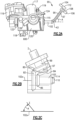
- FIG. 2B shows the angle drive in more detail.
- the low speed tower shaft 97 drives a gear 84 which is a bevel gear and engages a gear 86 to drive the low speed input shaft 114.
- the high speed tower shaft 99 drives the bevel gear 80 which is engaged to and drives a bevel gear 82 to in turn drive the high speed input shaft 110.
- the low speed input shaft 114 is concentric with and received outside the high speed input shaft 110, the opposite is true of the shafts 97 and 99 in the angle drive input 95.
- the low speed tower shaft 97 is inside of the high speed tower shaft 99.
- the high speed input shaft 110 is concentric with and received outside the low speed input shaft 114, and/or the high speed tower shaft 99 is inside of the low speed tower shaft 97.
- a rotation axis I of the shafts 97 and 99 is shown at the angle A in Figure 2C relative to a drive axis 102x of the shafts 114 and 110.
- the angle A may be between 5° and 85°.
- this disclosure has particular application for an accessory gearbox in a two spool engine, and wherein the low speed input shaft is driven by a low spool which also drives a fan through a gear reduction.
- Such low speed spools can have a wide speed excursion, and say on the order of 80%.
- Figure 3A shows the input shaft 102.
- the high speed input shaft 110 ( Figs. 2B and 3C ) drives gears 130A, 130B, 130C, and 130D. These gears all, in turn, drive the accessory such as shown in Figure 2A .
- a bevel gear at the end of the gear 130D drives another gear 131, which is the drive gear for the boost compressor 122.
- the low speed input shaft 114 ( Figs. 2B and 3C ) drives a plurality of gears 128A, 128B, 128C, and 128D. These gears then drive the several low speed driven auxiliary systems.
- the gearbox could be said to be a V gearbox.
- the V gearbox is defined by two planes L and H.
- Gearbox plane L includes a plurality of rotational axes 128 of the gears 128A-128D.
- Plane H is the same, but with the rotational axes 130 of the gears 130A-130D.
- the axes 128 extend perpendicularly through the plane L and are parallel to each other. The same is true for the axes 130 in plane H.
- the planes L, H can be seen to define angles relative to a plane Z, which bisects the rotational axis 102X of the shafts 110 and 114.
- the angles defined by the planes L, H extend in opposed directions relative to the axis 102X.
- the boost compressor 122 rotates about a drive axis 122x, which is concentric with the axis 102X.
- Figure 3C shows the high speed input shaft 110 packaged within the low speed input shaft 114.
- Figure 3D shows a gear 138, which is driven by the shaft 110 to, in turn, engage and drive the gear 130D, and then the other gears as shown in Figure 3A .
- a bevel gear 134 driven by shaft 114 drives gear 128A and, in turn, the other gears.
- Figure 4 shows an alternative embodiment 149.
- the input 102 drives a first shaft 150 extending along an axis and driving a plurality of bevel gears 151, which engage and drive a plurality of gears 152A-152C.
- this arrangement replaces the engaged gears 130A-130D.
- a shaft 154 drives bevel gears 155, which engage and drive a plurality of gears 156A-156C.
- the boost compressor 122 is shown driven at the end of the shaft 150.
- the input 102 is not shown here it may be structured as in Figure 3D .
- V transmission and the packaging of the boost compressor 122 such that it is driven on an axis which is distinct from the axes 128/130 in planes L, H provides more compact packaging, while adding the additional boost compressor 122.
- a gas turbine engine under this disclosure has a low speed input shaft connected to a low speed tower shaft, in turn connected to a lower speed spool and a high speed input connected to a high speed tower shaft, in turn connected to a higher speed spool, the low speed input shaft being connected to drive a first plurality of accessories.
- the high speed input shaft is connected to drive a second plurality of accessories.
- the first plurality of accessories rotate about a first set of rotational axes, which are parallel to each other but spaced along an axial input direction and are perpendicular to a first plane.
- the second plurality of accessories rotate about a second set of rotational axes, which are parallel to each other and spaced along an axial input direction and perpendicular to a second plane.
- the first and second planes extend in opposed directions away from a drive input axis of the high speed input shaft and the low speed input shaft.
- the high speed tower shaft and the low speed tower shaft are coaxial and rotating about a common axis, and provide an angle drive into the low speed input shaft and the high speed input shaft, respectively.
Landscapes
- Engineering & Computer Science (AREA)
- General Engineering & Computer Science (AREA)
- Chemical & Material Sciences (AREA)
- Combustion & Propulsion (AREA)
- Mechanical Engineering (AREA)
- Gear Transmission (AREA)
- Retarders (AREA)
Claims (9)
- Gasturbinentriebwerk (20), umfassend:eine Eingangswelle mit niedriger Drehzahl (114), die mit einer Turmwelle mit niedriger Drehzahl (97) verbunden ist, die wiederum mit einer Spule mit niedrigerer Drehzahl (30) verbunden ist, und eine Eingangswelle mit hoher Drehzahl (110), die mit einer Turmwelle mit hoher Drehzahl (99) verbunden ist, die wiederum mit einer Spule mit höherer Drehzahl (32) verbunden ist, wobei die Eingangswelle mit niedriger Drehzahl (114) verbunden ist, um eine erste Vielzahl von Hilfsvorrichtungen anzutreiben und die Eingangswelle mit hoher Drehzahl (110) verbunden ist, um eine zweite Vielzahl von Hilfsvorrichtungen anzutreiben; undwobei die Turmwelle mit hoher Drehzahl (99) und die Turmwelle mit niedriger Drehzahl (97) koaxial sind und sich um eine gemeinsame Achse (I) drehen und einen Winkelantrieb in die Eingangswelle mit niedriger Drehzahl (114) bzw. die Eingangswelle mit hoher Drehzahl (110) bereitstellen;
wobei sich die erste Vielzahl von Hilfsvorrichtungen um einen ersten Satz von Rotationsachsen (128) dreht, die parallel zueinander, aber entlang einer axialen Eingangsrichtung beabstandet und senkrecht zu einer erste Ebene (L) sind, und sich die zweite Vielzahl von Hilfsvorrichtungen um einen zweiten Satz von Rotationsachsen (130) dreht, die parallel zueinander und entlang einer axialen Eingangsrichtung beabstandet und senkrecht zu einer zweiten Ebene (H) sind, wobei sich die erste und die zweite Ebene (L, H) in entgegengesetzte Richtungen von einer Antriebseingangsachse (102x) der Eingangswelle mit hoher Drehzahl (110) und der Eingangswelle mit niedriger Drehzahl (114) weg erstrecken; undwobei die Eingangswelle mit niedriger Drehzahl (114) und die Eingangswelle mit hoher Drehzahl (110) konzentrisch sind. - Gasturbinentriebwerk (20) nach Anspruch 1, wobei die Eingangswelle mit hoher Drehzahl (110) hohl ist und die Eingangswelle mit niedriger Drehzahl (114) innerhalb oder außerhalb der Eingangswelle mit hoher Drehzahl (110) positioniert ist.
- Gasturbinentriebwerk (20) nach Anspruch 1 oder 2, wobei die Turmwelle mit hoher Drehzahl (99) innerhalb oder außerhalb der Turmwelle mit niedriger Drehzahl (97) aufgenommen ist.
- Gasturbinentriebwerk (20) nach einem der vorhergehenden Ansprüche, wobei jede der Turmwellen mit niedriger Drehzahl und mit hoher Drehzahl (97, 99) ein Kegelrad (84, 80) antreibt, um wiederum ein Kegelrad (86, 82) anzutreiben, das mit der Eingangswelle mit niedriger Drehzahl (110) und der Eingangswelle mit hoher Drehzahl (110) verbunden ist.
- Gasturbinentriebwerk (20) nach einem der vorhergehenden Ansprüche, wobei eine Antriebsachse (I) der Turmwelle mit niedriger Drehzahl (97) und der Turmwelle mit hoher Drehzahl (99) in einem nicht rechtwinkligen und nicht parallelen Winkel (A) relativ zu einer Antriebsachse (102x) der Eingangswelle mit niedriger Drehzahl (114) und der Eingangswelle mit hoher Drehzahl (110) ist.
- Gasturbinentriebwerk (20) nach Anspruch 5, wobei der Winkel (A) zwischen 5° und 85° liegt.
- Gasturbinentriebwerk (20) nach einem der vorhergehenden Ansprüche, wobei jede der Eingangswellen mit niedriger Drehzahl und mit hoher Drehzahl (114, 110) ein Kegelrad (134, 138) antreibt und die Kegelräder (134, 138) wiederum Zahnräder (128A-D, 130A-D) antreiben, um die erste Vielzahl von Hilfsvorrichtungen bzw. die zweite Vielzahl von Hilfsvorrichtungen anzutreiben.
- Gasturbinentriebwerk (20) nach Anspruch 7, wobei jedes der Kegelräder (134, 138) ein Zahnrad (128A, 130A) antreibt, das in Eingriff genommen wird, um ein anderes Zahnrad (128B, 130B) anzutreiben, und das andere Zahnrad (128B, 130B) in Eingriff genommen wird, um ein drittes Zahnrad (128C, 130C) anzutreiben.
- Gasturbinentriebwerk (20) nach einem der vorhergehenden Ansprüche, wobei ein Eingangszahnrad für die Eingangswelle mit niedriger Drehzahl (114) eine erste Welle (150) mit einer Vielzahl von Kegelrädern (151) antreibt, wobei jedes der Kegelräder (151) ein zugeordnetes Antriebszahnrad (152A-C) für eine der ersten Vielzahl von Hilfsvorrichtungen antreibt und ein Eingangszahnrad für die Eingangswelle mit hoher Drehzahl (110) eine zweite Welle (154) mit einer Vielzahl von Kegelrädern (155) antreibt, wobei jedes Kegelrad (155) ein zugehöriges Antriebszahnrad (156A-C) antreibt, das einer der zweiten Vielzahl von Hilfsvorrichtungen zugeordnet ist.
Applications Claiming Priority (1)
| Application Number | Priority Date | Filing Date | Title |
|---|---|---|---|
| US16/274,360 US20200256430A1 (en) | 2019-02-13 | 2019-02-13 | Angle accessory gearbox for gas turbine engine |
Publications (3)
| Publication Number | Publication Date |
|---|---|
| EP3696392A1 EP3696392A1 (de) | 2020-08-19 |
| EP3696392B1 EP3696392B1 (de) | 2022-04-20 |
| EP3696392B2 true EP3696392B2 (de) | 2024-12-25 |
Family
ID=69581959
Family Applications (1)
| Application Number | Title | Priority Date | Filing Date |
|---|---|---|---|
| EP20157024.9A Active EP3696392B2 (de) | 2019-02-13 | 2020-02-12 | Winkelhilfsgetriebe für ein gasturbinentriebwerk |
Country Status (2)
| Country | Link |
|---|---|
| US (1) | US20200256430A1 (de) |
| EP (1) | EP3696392B2 (de) |
Family Cites Families (10)
| Publication number | Priority date | Publication date | Assignee | Title |
|---|---|---|---|---|
| US7386983B2 (en) | 2004-02-25 | 2008-06-17 | United Technologies Corporation | Apparatus for driving an accessory gearbox in a gas turbine engine |
| US20050183540A1 (en) * | 2004-02-25 | 2005-08-25 | Miller Guy W. | Apparatus for driving an accessory gearbox in a gas turbine engine |
| FR2882096B1 (fr) | 2005-02-11 | 2012-04-20 | Snecma Moteurs | Turbomoteur a double corps avec des moyens de prise de mouvement sur les rotors basse pression et haute pression, module de prise de mouvement pour le turbomoteur et procede de montage du turbomoteur |
| FR2921423B1 (fr) * | 2007-09-25 | 2014-04-25 | Snecma | Turbomachine a double corps, avec double prelevement de puissance |
| US20090205341A1 (en) | 2008-02-20 | 2009-08-20 | Muldoon Marc J | Gas turbine engine with twin towershaft accessory gearbox |
| FR3011882B1 (fr) | 2013-10-11 | 2018-01-26 | Hispano Suiza Sa | Boitier d'entrainement d'accessoires pour turbomachine |
| FR3026787B1 (fr) | 2014-10-07 | 2019-04-19 | Safran Transmission Systems | Transmission spinale compacte |
| US10358981B2 (en) * | 2017-04-11 | 2019-07-23 | United Technologies Corporation | High and low spool accessory gearbox drive |
| US10526976B2 (en) * | 2017-04-27 | 2020-01-07 | United Technologies Corporation | Tangential drive for gas turbine engine accessories |
| US10634064B1 (en) | 2018-10-11 | 2020-04-28 | United Technologies Corporation | Accessory gearbox with superposition gearbox |
-
2019
- 2019-02-13 US US16/274,360 patent/US20200256430A1/en not_active Abandoned
-
2020
- 2020-02-12 EP EP20157024.9A patent/EP3696392B2/de active Active
Also Published As
| Publication number | Publication date |
|---|---|
| EP3696392A1 (de) | 2020-08-19 |
| EP3696392B1 (de) | 2022-04-20 |
| US20200256430A1 (en) | 2020-08-13 |
Similar Documents
| Publication | Publication Date | Title |
|---|---|---|
| EP3431738B1 (de) | Tangentialantrieb für gasturbinennebenverbraucher | |
| US11459957B2 (en) | Gas turbine engine with non-epicyclic gear reduction system | |
| EP3628850B1 (de) | Getriebe für gasturbinenmotoren | |
| CA2856723C (en) | Gas turbine engine with high speed low pressure turbine section | |
| US10605173B2 (en) | High and low spool accessory gearbox drive | |
| EP3628847B1 (de) | Drehmomentarmer motorstart mit doppelter wellenleistungsentnahme mit überlagerungsgetriebe | |
| EP4215737B1 (de) | Doppelspulenleistungsextraktion mit überlagerungsgetriebe | |
| EP3054141B1 (de) | Reduktionsgetriebe für getriebefan | |
| EP4261400A1 (de) | Getriebeanordnung für nebenaggregate mit konstanter geschwindigkeit | |
| EP3696391B1 (de) | Hilfsgetriebe für ein gasturbinentriebwerk mit variabler übersetzung | |
| EP3696390B1 (de) | Hilfsgetriebe für gasturbinentriebwerk mit kompressorantrieb | |
| EP3696392B1 (de) | Winkelhilfsgetriebe für ein gasturbinentriebwerk |
Legal Events
| Date | Code | Title | Description |
|---|---|---|---|
| PUAI | Public reference made under article 153(3) epc to a published international application that has entered the european phase |
Free format text: ORIGINAL CODE: 0009012 |
|
| STAA | Information on the status of an ep patent application or granted ep patent |
Free format text: STATUS: THE APPLICATION HAS BEEN PUBLISHED |
|
| AK | Designated contracting states |
Kind code of ref document: A1 Designated state(s): AL AT BE BG CH CY CZ DE DK EE ES FI FR GB GR HR HU IE IS IT LI LT LU LV MC MK MT NL NO PL PT RO RS SE SI SK SM TR |
|
| AX | Request for extension of the european patent |
Extension state: BA ME |
|
| STAA | Information on the status of an ep patent application or granted ep patent |
Free format text: STATUS: REQUEST FOR EXAMINATION WAS MADE |
|
| 17P | Request for examination filed |
Effective date: 20210216 |
|
| RAP1 | Party data changed (applicant data changed or rights of an application transferred) |
Owner name: RAYTHEON TECHNOLOGIES CORPORATION |
|
| RBV | Designated contracting states (corrected) |
Designated state(s): AL AT BE BG CH CY CZ DE DK EE ES FI FR GB GR HR HU IE IS IT LI LT LU LV MC MK MT NL NO PL PT RO RS SE SI SK SM TR |
|
| GRAP | Despatch of communication of intention to grant a patent |
Free format text: ORIGINAL CODE: EPIDOSNIGR1 |
|
| STAA | Information on the status of an ep patent application or granted ep patent |
Free format text: STATUS: GRANT OF PATENT IS INTENDED |
|
| INTG | Intention to grant announced |
Effective date: 20210810 |
|
| GRAJ | Information related to disapproval of communication of intention to grant by the applicant or resumption of examination proceedings by the epo deleted |
Free format text: ORIGINAL CODE: EPIDOSDIGR1 |
|
| STAA | Information on the status of an ep patent application or granted ep patent |
Free format text: STATUS: REQUEST FOR EXAMINATION WAS MADE |
|
| GRAP | Despatch of communication of intention to grant a patent |
Free format text: ORIGINAL CODE: EPIDOSNIGR1 |
|
| STAA | Information on the status of an ep patent application or granted ep patent |
Free format text: STATUS: GRANT OF PATENT IS INTENDED |
|
| INTC | Intention to grant announced (deleted) | ||
| INTG | Intention to grant announced |
Effective date: 20220125 |
|
| GRAS | Grant fee paid |
Free format text: ORIGINAL CODE: EPIDOSNIGR3 |
|
| GRAA | (expected) grant |
Free format text: ORIGINAL CODE: 0009210 |
|
| STAA | Information on the status of an ep patent application or granted ep patent |
Free format text: STATUS: THE PATENT HAS BEEN GRANTED |
|
| AK | Designated contracting states |
Kind code of ref document: B1 Designated state(s): AL AT BE BG CH CY CZ DE DK EE ES FI FR GB GR HR HU IE IS IT LI LT LU LV MC MK MT NL NO PL PT RO RS SE SI SK SM TR |
|
| REG | Reference to a national code |
Ref country code: GB Ref legal event code: FG4D |
|
| REG | Reference to a national code |
Ref country code: CH Ref legal event code: EP |
|
| REG | Reference to a national code |
Ref country code: IE Ref legal event code: FG4D |
|
| REG | Reference to a national code |
Ref country code: DE Ref legal event code: R096 Ref document number: 602020002693 Country of ref document: DE |
|
| REG | Reference to a national code |
Ref country code: AT Ref legal event code: REF Ref document number: 1485318 Country of ref document: AT Kind code of ref document: T Effective date: 20220515 |
|
| REG | Reference to a national code |
Ref country code: LT Ref legal event code: MG9D |
|
| REG | Reference to a national code |
Ref country code: NL Ref legal event code: MP Effective date: 20220420 |
|
| REG | Reference to a national code |
Ref country code: AT Ref legal event code: MK05 Ref document number: 1485318 Country of ref document: AT Kind code of ref document: T Effective date: 20220420 |
|
| PG25 | Lapsed in a contracting state [announced via postgrant information from national office to epo] |
Ref country code: NL Free format text: LAPSE BECAUSE OF FAILURE TO SUBMIT A TRANSLATION OF THE DESCRIPTION OR TO PAY THE FEE WITHIN THE PRESCRIBED TIME-LIMIT Effective date: 20220420 |
|
| PG25 | Lapsed in a contracting state [announced via postgrant information from national office to epo] |
Ref country code: SE Free format text: LAPSE BECAUSE OF FAILURE TO SUBMIT A TRANSLATION OF THE DESCRIPTION OR TO PAY THE FEE WITHIN THE PRESCRIBED TIME-LIMIT Effective date: 20220420 Ref country code: PT Free format text: LAPSE BECAUSE OF FAILURE TO SUBMIT A TRANSLATION OF THE DESCRIPTION OR TO PAY THE FEE WITHIN THE PRESCRIBED TIME-LIMIT Effective date: 20220822 Ref country code: NO Free format text: LAPSE BECAUSE OF FAILURE TO SUBMIT A TRANSLATION OF THE DESCRIPTION OR TO PAY THE FEE WITHIN THE PRESCRIBED TIME-LIMIT Effective date: 20220720 Ref country code: LT Free format text: LAPSE BECAUSE OF FAILURE TO SUBMIT A TRANSLATION OF THE DESCRIPTION OR TO PAY THE FEE WITHIN THE PRESCRIBED TIME-LIMIT Effective date: 20220420 Ref country code: HR Free format text: LAPSE BECAUSE OF FAILURE TO SUBMIT A TRANSLATION OF THE DESCRIPTION OR TO PAY THE FEE WITHIN THE PRESCRIBED TIME-LIMIT Effective date: 20220420 Ref country code: GR Free format text: LAPSE BECAUSE OF FAILURE TO SUBMIT A TRANSLATION OF THE DESCRIPTION OR TO PAY THE FEE WITHIN THE PRESCRIBED TIME-LIMIT Effective date: 20220721 Ref country code: FI Free format text: LAPSE BECAUSE OF FAILURE TO SUBMIT A TRANSLATION OF THE DESCRIPTION OR TO PAY THE FEE WITHIN THE PRESCRIBED TIME-LIMIT Effective date: 20220420 Ref country code: ES Free format text: LAPSE BECAUSE OF FAILURE TO SUBMIT A TRANSLATION OF THE DESCRIPTION OR TO PAY THE FEE WITHIN THE PRESCRIBED TIME-LIMIT Effective date: 20220420 Ref country code: BG Free format text: LAPSE BECAUSE OF FAILURE TO SUBMIT A TRANSLATION OF THE DESCRIPTION OR TO PAY THE FEE WITHIN THE PRESCRIBED TIME-LIMIT Effective date: 20220720 Ref country code: AT Free format text: LAPSE BECAUSE OF FAILURE TO SUBMIT A TRANSLATION OF THE DESCRIPTION OR TO PAY THE FEE WITHIN THE PRESCRIBED TIME-LIMIT Effective date: 20220420 |
|
| PG25 | Lapsed in a contracting state [announced via postgrant information from national office to epo] |
Ref country code: RS Free format text: LAPSE BECAUSE OF FAILURE TO SUBMIT A TRANSLATION OF THE DESCRIPTION OR TO PAY THE FEE WITHIN THE PRESCRIBED TIME-LIMIT Effective date: 20220420 Ref country code: PL Free format text: LAPSE BECAUSE OF FAILURE TO SUBMIT A TRANSLATION OF THE DESCRIPTION OR TO PAY THE FEE WITHIN THE PRESCRIBED TIME-LIMIT Effective date: 20220420 Ref country code: LV Free format text: LAPSE BECAUSE OF FAILURE TO SUBMIT A TRANSLATION OF THE DESCRIPTION OR TO PAY THE FEE WITHIN THE PRESCRIBED TIME-LIMIT Effective date: 20220420 Ref country code: IS Free format text: LAPSE BECAUSE OF FAILURE TO SUBMIT A TRANSLATION OF THE DESCRIPTION OR TO PAY THE FEE WITHIN THE PRESCRIBED TIME-LIMIT Effective date: 20220820 |
|
| REG | Reference to a national code |
Ref country code: DE Ref legal event code: R026 Ref document number: 602020002693 Country of ref document: DE |
|
| PLBI | Opposition filed |
Free format text: ORIGINAL CODE: 0009260 |
|
| PG25 | Lapsed in a contracting state [announced via postgrant information from national office to epo] |
Ref country code: SM Free format text: LAPSE BECAUSE OF FAILURE TO SUBMIT A TRANSLATION OF THE DESCRIPTION OR TO PAY THE FEE WITHIN THE PRESCRIBED TIME-LIMIT Effective date: 20220420 Ref country code: SK Free format text: LAPSE BECAUSE OF FAILURE TO SUBMIT A TRANSLATION OF THE DESCRIPTION OR TO PAY THE FEE WITHIN THE PRESCRIBED TIME-LIMIT Effective date: 20220420 Ref country code: RO Free format text: LAPSE BECAUSE OF FAILURE TO SUBMIT A TRANSLATION OF THE DESCRIPTION OR TO PAY THE FEE WITHIN THE PRESCRIBED TIME-LIMIT Effective date: 20220420 Ref country code: EE Free format text: LAPSE BECAUSE OF FAILURE TO SUBMIT A TRANSLATION OF THE DESCRIPTION OR TO PAY THE FEE WITHIN THE PRESCRIBED TIME-LIMIT Effective date: 20220420 Ref country code: DK Free format text: LAPSE BECAUSE OF FAILURE TO SUBMIT A TRANSLATION OF THE DESCRIPTION OR TO PAY THE FEE WITHIN THE PRESCRIBED TIME-LIMIT Effective date: 20220420 Ref country code: CZ Free format text: LAPSE BECAUSE OF FAILURE TO SUBMIT A TRANSLATION OF THE DESCRIPTION OR TO PAY THE FEE WITHIN THE PRESCRIBED TIME-LIMIT Effective date: 20220420 |
|
| PLAX | Notice of opposition and request to file observation + time limit sent |
Free format text: ORIGINAL CODE: EPIDOSNOBS2 |
|
| 26 | Opposition filed |
Opponent name: SAFRAN AIRCRAFT ENGINES Effective date: 20230119 |
|
| PG25 | Lapsed in a contracting state [announced via postgrant information from national office to epo] |
Ref country code: AL Free format text: LAPSE BECAUSE OF FAILURE TO SUBMIT A TRANSLATION OF THE DESCRIPTION OR TO PAY THE FEE WITHIN THE PRESCRIBED TIME-LIMIT Effective date: 20220420 |
|
| PG25 | Lapsed in a contracting state [announced via postgrant information from national office to epo] |
Ref country code: SI Free format text: LAPSE BECAUSE OF FAILURE TO SUBMIT A TRANSLATION OF THE DESCRIPTION OR TO PAY THE FEE WITHIN THE PRESCRIBED TIME-LIMIT Effective date: 20220420 |
|
| PLBB | Reply of patent proprietor to notice(s) of opposition received |
Free format text: ORIGINAL CODE: EPIDOSNOBS3 |
|
| P01 | Opt-out of the competence of the unified patent court (upc) registered |
Effective date: 20230521 |
|
| PG25 | Lapsed in a contracting state [announced via postgrant information from national office to epo] |
Ref country code: MC Free format text: LAPSE BECAUSE OF FAILURE TO SUBMIT A TRANSLATION OF THE DESCRIPTION OR TO PAY THE FEE WITHIN THE PRESCRIBED TIME-LIMIT Effective date: 20220420 |
|
| REG | Reference to a national code |
Ref country code: CH Ref legal event code: PL |
|
| REG | Reference to a national code |
Ref country code: BE Ref legal event code: MM Effective date: 20230228 |
|
| PG25 | Lapsed in a contracting state [announced via postgrant information from national office to epo] |
Ref country code: LU Free format text: LAPSE BECAUSE OF NON-PAYMENT OF DUE FEES Effective date: 20230212 Ref country code: LI Free format text: LAPSE BECAUSE OF NON-PAYMENT OF DUE FEES Effective date: 20230228 Ref country code: CH Free format text: LAPSE BECAUSE OF NON-PAYMENT OF DUE FEES Effective date: 20230228 |
|
| RAP4 | Party data changed (patent owner data changed or rights of a patent transferred) |
Owner name: RTX CORPORATION |
|
| REG | Reference to a national code |
Ref country code: IE Ref legal event code: MM4A |
|
| PG25 | Lapsed in a contracting state [announced via postgrant information from national office to epo] |
Ref country code: IT Free format text: LAPSE BECAUSE OF FAILURE TO SUBMIT A TRANSLATION OF THE DESCRIPTION OR TO PAY THE FEE WITHIN THE PRESCRIBED TIME-LIMIT Effective date: 20220420 Ref country code: IE Free format text: LAPSE BECAUSE OF NON-PAYMENT OF DUE FEES Effective date: 20230212 |
|
| PG25 | Lapsed in a contracting state [announced via postgrant information from national office to epo] |
Ref country code: BE Free format text: LAPSE BECAUSE OF NON-PAYMENT OF DUE FEES Effective date: 20230228 |
|
| PG25 | Lapsed in a contracting state [announced via postgrant information from national office to epo] |
Ref country code: BG Free format text: LAPSE BECAUSE OF FAILURE TO SUBMIT A TRANSLATION OF THE DESCRIPTION OR TO PAY THE FEE WITHIN THE PRESCRIBED TIME-LIMIT Effective date: 20220420 |
|
| PUAH | Patent maintained in amended form |
Free format text: ORIGINAL CODE: 0009272 |
|
| STAA | Information on the status of an ep patent application or granted ep patent |
Free format text: STATUS: PATENT MAINTAINED AS AMENDED |
|
| PG25 | Lapsed in a contracting state [announced via postgrant information from national office to epo] |
Ref country code: BG Free format text: LAPSE BECAUSE OF FAILURE TO SUBMIT A TRANSLATION OF THE DESCRIPTION OR TO PAY THE FEE WITHIN THE PRESCRIBED TIME-LIMIT Effective date: 20220420 |
|
| 27A | Patent maintained in amended form |
Effective date: 20241225 |
|
| AK | Designated contracting states |
Kind code of ref document: B2 Designated state(s): AL AT BE BG CH CY CZ DE DK EE ES FI FR GB GR HR HU IE IS IT LI LT LU LV MC MK MT NL NO PL PT RO RS SE SI SK SM TR |
|
| REG | Reference to a national code |
Ref country code: DE Ref legal event code: R102 Ref document number: 602020002693 Country of ref document: DE |
|
| PGFP | Annual fee paid to national office [announced via postgrant information from national office to epo] |
Ref country code: DE Payment date: 20250122 Year of fee payment: 6 |
|
| PGFP | Annual fee paid to national office [announced via postgrant information from national office to epo] |
Ref country code: FR Payment date: 20250122 Year of fee payment: 6 |
|
| PGFP | Annual fee paid to national office [announced via postgrant information from national office to epo] |
Ref country code: GB Payment date: 20250124 Year of fee payment: 6 |
|
| PG25 | Lapsed in a contracting state [announced via postgrant information from national office to epo] |
Ref country code: CY Free format text: LAPSE BECAUSE OF FAILURE TO SUBMIT A TRANSLATION OF THE DESCRIPTION OR TO PAY THE FEE WITHIN THE PRESCRIBED TIME-LIMIT; INVALID AB INITIO Effective date: 20200212 |
|
| PG25 | Lapsed in a contracting state [announced via postgrant information from national office to epo] |
Ref country code: HU Free format text: LAPSE BECAUSE OF FAILURE TO SUBMIT A TRANSLATION OF THE DESCRIPTION OR TO PAY THE FEE WITHIN THE PRESCRIBED TIME-LIMIT; INVALID AB INITIO Effective date: 20200212 |
|
| REG | Reference to a national code |
Ref country code: DE Ref legal event code: R081 Ref document number: 602020002693 Country of ref document: DE Owner name: RTX CORPORATION (N.D.GES.D. STAATES DELAWARE),, US Free format text: FORMER OWNER: RAYTHEON TECHNOLOGIES CORP., FARMINGTON, CT, US |
|
| PG25 | Lapsed in a contracting state [announced via postgrant information from national office to epo] |
Ref country code: TR Free format text: LAPSE BECAUSE OF FAILURE TO SUBMIT A TRANSLATION OF THE DESCRIPTION OR TO PAY THE FEE WITHIN THE PRESCRIBED TIME-LIMIT Effective date: 20220420 |