EP3696386A1 - Valve assembly for a dual volute turbocharger and dual volute turbocharger including the same - Google Patents
Valve assembly for a dual volute turbocharger and dual volute turbocharger including the same Download PDFInfo
- Publication number
- EP3696386A1 EP3696386A1 EP20157039.7A EP20157039A EP3696386A1 EP 3696386 A1 EP3696386 A1 EP 3696386A1 EP 20157039 A EP20157039 A EP 20157039A EP 3696386 A1 EP3696386 A1 EP 3696386A1
- Authority
- EP
- European Patent Office
- Prior art keywords
- valve
- valve member
- turbine housing
- exhaust gas
- interior
- Prior art date
- Legal status (The legal status is an assumption and is not a legal conclusion. Google has not performed a legal analysis and makes no representation as to the accuracy of the status listed.)
- Granted
Links
Images




Classifications
-
- F—MECHANICAL ENGINEERING; LIGHTING; HEATING; WEAPONS; BLASTING
- F02—COMBUSTION ENGINES; HOT-GAS OR COMBUSTION-PRODUCT ENGINE PLANTS
- F02B—INTERNAL-COMBUSTION PISTON ENGINES; COMBUSTION ENGINES IN GENERAL
- F02B37/00—Engines characterised by provision of pumps driven at least for part of the time by exhaust
- F02B37/12—Control of the pumps
- F02B37/22—Control of the pumps by varying cross-section of exhaust passages or air passages, e.g. by throttling turbine inlets or outlets or by varying effective number of guide conduits
-
- F—MECHANICAL ENGINEERING; LIGHTING; HEATING; WEAPONS; BLASTING
- F01—MACHINES OR ENGINES IN GENERAL; ENGINE PLANTS IN GENERAL; STEAM ENGINES
- F01D—NON-POSITIVE DISPLACEMENT MACHINES OR ENGINES, e.g. STEAM TURBINES
- F01D17/00—Regulating or controlling by varying flow
- F01D17/10—Final actuators
- F01D17/12—Final actuators arranged in stator parts
- F01D17/14—Final actuators arranged in stator parts varying effective cross-sectional area of nozzles or guide conduits
- F01D17/141—Final actuators arranged in stator parts varying effective cross-sectional area of nozzles or guide conduits by means of shiftable members or valves obturating part of the flow path
- F01D17/143—Final actuators arranged in stator parts varying effective cross-sectional area of nozzles or guide conduits by means of shiftable members or valves obturating part of the flow path the shiftable member being a wall, or part thereof of a radial diffuser
-
- F—MECHANICAL ENGINEERING; LIGHTING; HEATING; WEAPONS; BLASTING
- F01—MACHINES OR ENGINES IN GENERAL; ENGINE PLANTS IN GENERAL; STEAM ENGINES
- F01D—NON-POSITIVE DISPLACEMENT MACHINES OR ENGINES, e.g. STEAM TURBINES
- F01D9/00—Stators
- F01D9/02—Nozzles; Nozzle boxes; Stator blades; Guide conduits, e.g. individual nozzles
- F01D9/026—Scrolls for radial machines or engines
-
- F—MECHANICAL ENGINEERING; LIGHTING; HEATING; WEAPONS; BLASTING
- F02—COMBUSTION ENGINES; HOT-GAS OR COMBUSTION-PRODUCT ENGINE PLANTS
- F02B—INTERNAL-COMBUSTION PISTON ENGINES; COMBUSTION ENGINES IN GENERAL
- F02B37/00—Engines characterised by provision of pumps driven at least for part of the time by exhaust
- F02B37/02—Gas passages between engine outlet and pump drive, e.g. reservoirs
- F02B37/025—Multiple scrolls or multiple gas passages guiding the gas to the pump drive
-
- F—MECHANICAL ENGINEERING; LIGHTING; HEATING; WEAPONS; BLASTING
- F02—COMBUSTION ENGINES; HOT-GAS OR COMBUSTION-PRODUCT ENGINE PLANTS
- F02B—INTERNAL-COMBUSTION PISTON ENGINES; COMBUSTION ENGINES IN GENERAL
- F02B37/00—Engines characterised by provision of pumps driven at least for part of the time by exhaust
- F02B37/12—Control of the pumps
- F02B37/18—Control of the pumps by bypassing exhaust from the inlet to the outlet of turbine or to the atmosphere
- F02B37/183—Arrangements of bypass valves or actuators therefor
-
- F—MECHANICAL ENGINEERING; LIGHTING; HEATING; WEAPONS; BLASTING
- F02—COMBUSTION ENGINES; HOT-GAS OR COMBUSTION-PRODUCT ENGINE PLANTS
- F02B—INTERNAL-COMBUSTION PISTON ENGINES; COMBUSTION ENGINES IN GENERAL
- F02B37/00—Engines characterised by provision of pumps driven at least for part of the time by exhaust
- F02B37/12—Control of the pumps
- F02B37/18—Control of the pumps by bypassing exhaust from the inlet to the outlet of turbine or to the atmosphere
- F02B37/183—Arrangements of bypass valves or actuators therefor
- F02B37/186—Arrangements of actuators or linkage for bypass valves
-
- F—MECHANICAL ENGINEERING; LIGHTING; HEATING; WEAPONS; BLASTING
- F02—COMBUSTION ENGINES; HOT-GAS OR COMBUSTION-PRODUCT ENGINE PLANTS
- F02D—CONTROLLING COMBUSTION ENGINES
- F02D23/00—Controlling engines characterised by their being supercharged
-
- F—MECHANICAL ENGINEERING; LIGHTING; HEATING; WEAPONS; BLASTING
- F04—POSITIVE - DISPLACEMENT MACHINES FOR LIQUIDS; PUMPS FOR LIQUIDS OR ELASTIC FLUIDS
- F04D—NON-POSITIVE-DISPLACEMENT PUMPS
- F04D15/00—Control, e.g. regulation, of pumps, pumping installations or systems
- F04D15/0005—Control, e.g. regulation, of pumps, pumping installations or systems by using valves
- F04D15/0022—Control, e.g. regulation, of pumps, pumping installations or systems by using valves throttling valves or valves varying the pump inlet opening or the outlet opening
-
- F—MECHANICAL ENGINEERING; LIGHTING; HEATING; WEAPONS; BLASTING
- F16—ENGINEERING ELEMENTS AND UNITS; GENERAL MEASURES FOR PRODUCING AND MAINTAINING EFFECTIVE FUNCTIONING OF MACHINES OR INSTALLATIONS; THERMAL INSULATION IN GENERAL
- F16K—VALVES; TAPS; COCKS; ACTUATING-FLOATS; DEVICES FOR VENTING OR AERATING
- F16K11/00—Multiple-way valves, e.g. mixing valves; Pipe fittings incorporating such valves
- F16K11/02—Multiple-way valves, e.g. mixing valves; Pipe fittings incorporating such valves with all movable sealing faces moving as one unit
- F16K11/04—Multiple-way valves, e.g. mixing valves; Pipe fittings incorporating such valves with all movable sealing faces moving as one unit comprising only lift valves
-
- F—MECHANICAL ENGINEERING; LIGHTING; HEATING; WEAPONS; BLASTING
- F16—ENGINEERING ELEMENTS AND UNITS; GENERAL MEASURES FOR PRODUCING AND MAINTAINING EFFECTIVE FUNCTIONING OF MACHINES OR INSTALLATIONS; THERMAL INSULATION IN GENERAL
- F16K—VALVES; TAPS; COCKS; ACTUATING-FLOATS; DEVICES FOR VENTING OR AERATING
- F16K11/00—Multiple-way valves, e.g. mixing valves; Pipe fittings incorporating such valves
- F16K11/10—Multiple-way valves, e.g. mixing valves; Pipe fittings incorporating such valves with two or more closure members not moving as a unit
- F16K11/14—Multiple-way valves, e.g. mixing valves; Pipe fittings incorporating such valves with two or more closure members not moving as a unit operated by one actuating member, e.g. a handle
- F16K11/16—Multiple-way valves, e.g. mixing valves; Pipe fittings incorporating such valves with two or more closure members not moving as a unit operated by one actuating member, e.g. a handle which only slides, or only turns, or only swings in one plane
- F16K11/161—Multiple-way valves, e.g. mixing valves; Pipe fittings incorporating such valves with two or more closure members not moving as a unit operated by one actuating member, e.g. a handle which only slides, or only turns, or only swings in one plane only slides
-
- F—MECHANICAL ENGINEERING; LIGHTING; HEATING; WEAPONS; BLASTING
- F01—MACHINES OR ENGINES IN GENERAL; ENGINE PLANTS IN GENERAL; STEAM ENGINES
- F01D—NON-POSITIVE DISPLACEMENT MACHINES OR ENGINES, e.g. STEAM TURBINES
- F01D17/00—Regulating or controlling by varying flow
- F01D17/10—Final actuators
- F01D17/105—Final actuators by passing part of the fluid
-
- F—MECHANICAL ENGINEERING; LIGHTING; HEATING; WEAPONS; BLASTING
- F02—COMBUSTION ENGINES; HOT-GAS OR COMBUSTION-PRODUCT ENGINE PLANTS
- F02B—INTERNAL-COMBUSTION PISTON ENGINES; COMBUSTION ENGINES IN GENERAL
- F02B37/00—Engines characterised by provision of pumps driven at least for part of the time by exhaust
- F02B37/12—Control of the pumps
- F02B2037/122—Control of rotational speed of the pump
-
- F—MECHANICAL ENGINEERING; LIGHTING; HEATING; WEAPONS; BLASTING
- F05—INDEXING SCHEMES RELATING TO ENGINES OR PUMPS IN VARIOUS SUBCLASSES OF CLASSES F01-F04
- F05D—INDEXING SCHEME FOR ASPECTS RELATING TO NON-POSITIVE-DISPLACEMENT MACHINES OR ENGINES, GAS-TURBINES OR JET-PROPULSION PLANTS
- F05D2220/00—Application
- F05D2220/40—Application in turbochargers
-
- F—MECHANICAL ENGINEERING; LIGHTING; HEATING; WEAPONS; BLASTING
- F05—INDEXING SCHEMES RELATING TO ENGINES OR PUMPS IN VARIOUS SUBCLASSES OF CLASSES F01-F04
- F05D—INDEXING SCHEME FOR ASPECTS RELATING TO NON-POSITIVE-DISPLACEMENT MACHINES OR ENGINES, GAS-TURBINES OR JET-PROPULSION PLANTS
- F05D2270/00—Control
- F05D2270/30—Control parameters, e.g. input parameters
- F05D2270/301—Pressure
- F05D2270/3015—Pressure differential pressure
-
- F—MECHANICAL ENGINEERING; LIGHTING; HEATING; WEAPONS; BLASTING
- F05—INDEXING SCHEMES RELATING TO ENGINES OR PUMPS IN VARIOUS SUBCLASSES OF CLASSES F01-F04
- F05D—INDEXING SCHEME FOR ASPECTS RELATING TO NON-POSITIVE-DISPLACEMENT MACHINES OR ENGINES, GAS-TURBINES OR JET-PROPULSION PLANTS
- F05D2270/00—Control
- F05D2270/60—Control system actuates means
- F05D2270/66—Mechanical actuators
-
- Y—GENERAL TAGGING OF NEW TECHNOLOGICAL DEVELOPMENTS; GENERAL TAGGING OF CROSS-SECTIONAL TECHNOLOGIES SPANNING OVER SEVERAL SECTIONS OF THE IPC; TECHNICAL SUBJECTS COVERED BY FORMER USPC CROSS-REFERENCE ART COLLECTIONS [XRACs] AND DIGESTS
- Y02—TECHNOLOGIES OR APPLICATIONS FOR MITIGATION OR ADAPTATION AGAINST CLIMATE CHANGE
- Y02T—CLIMATE CHANGE MITIGATION TECHNOLOGIES RELATED TO TRANSPORTATION
- Y02T10/00—Road transport of goods or passengers
- Y02T10/10—Internal combustion engine [ICE] based vehicles
- Y02T10/12—Improving ICE efficiencies
Definitions
- the present invention generally relates to a valve assembly for controlling exhaust gas flow to a turbine housing interior of a dual volute turbocharger, and to a dual volute turbocharger including the valve assembly.
- Dual volute turbochargers receive exhaust gas from an internal combustion engine and deliver compressed air to the internal combustion engine. Dual volute turbochargers are used to increase power output of the internal combustion engine, lower fuel consumption of the internal combustion engine, and reduce emissions produced by the internal combustion engine. Delivery of compressed air to the internal combustion engine by the dual volute turbocharger allows the internal combustion engine to be smaller, yet able to develop the same or similar amount of horsepower as larger, naturally aspirated internal combustion engines. Having a smaller internal combustion engine for use in a vehicle reduces the mass and aerodynamic frontal area of the vehicle, which helps reduce fuel consumption of the internal combustion engine and improve fuel economy of the vehicle.
- Dual volute turbochargers include a turbine housing.
- the turbine housing has an interior surface defining a turbine housing interior, a first volute, a second volute, and a turbine housing outlet.
- the first and second volutes are each adapted for fluid communication with the internal combustion engine and the turbine housing interior for delivering exhaust gas from the internal combustion engine to the turbine housing interior.
- the turbine housing also includes a wall separating the first and second volutes and a valve seat. The wall and the valve seat collectively define a valve cavity.
- Dual volute turbochargers also include a valve assembly for controlling exhaust gas flow to the turbine housing interior.
- Conventional valve assemblies include a first valve member, a shaft, and a second valve member.
- the first valve member is coupled to the shaft and engageable with the wall of the turbine housing.
- the first valve member is movable between a first position where the first valve member is disposed in the valve cavity and engaged with the wall, a second position where first valve member is disposed in the valve cavity and disengaged with the wall, and a third position where the first valve member is disposed outside of the valve cavity.
- the second valve member is coupled to the shaft and engageable with the valve seat of the turbine housing.
- the second valve member is movable between a closed where the second valve member is engaged with the valve seat and an open position where the second valve member is disengaged with the valve seat.
- Conventional wastegate assemblies also include a biasing member configured to bias the first and/or second valve member in at least one of the aforementioned positions.
- exhaust gas flows through the first and second volutes and exerts a force on the first valve member, particularly when the first valve member is in the first and second positions.
- force exerted by exhaust gas on the first valve member causes wear of various components of the valve assembly, thereby decreasing efficiency of the dual volute turbocharger and ultimately leading to failure of the valve assembly.
- the biasing member is exposed to exhaust gas during operation of the turbocharger which causes wear of the biasing member. This wear of the biasing member also decreases efficiency of the dual volute turbocharger and ultimately leads to failure of the valve assembly.
- a dual volute turbocharger delivers compressed air to an internal combustion engine and receives exhaust gas from the internal combustion engine.
- the dual volute turbocharger includes a turbine housing.
- the turbine housing includes an interior surface defining a turbine housing interior, a first volute, a second volute, and a turbine housing outlet.
- the turbine housing interior is adapted to receive a turbine wheel.
- the first and second volutes are each adapted for fluid communication with the internal combustion engine and the turbine housing interior for delivering exhaust gas from the internal combustion engine to the turbine housing interior.
- the turbine housing outlet is in fluid communication with the turbine housing interior for discharging exhaust gas from the turbine housing interior.
- the turbine housing also includes a wall separating the first volute from the second volute.
- the turbine housing further includes a valve seat. The wall and the valve seat collectively define a valve cavity.
- the dual volute turbocharger also includes a valve assembly that controls exhaust gas flow from the first and second volutes to the turbine housing interior.
- the valve assembly includes a first valve member that is engageable with the wall of the turbine housing.
- the first valve member extends along an axis between a first end adapted to be proximal the wall of the turbine housing and a second end adapted to be distal the wall of the turbine housing.
- the first valve member defines a valve interior between the first and second ends.
- the first valve member is movable between a first position where the first valve member is disposed in the valve cavity and adjacent the wall of the turbine housing for restricting exhaust gas from flowing between the first and second volutes, a second position where the first valve member is disposed in the valve cavity and spaced from the wall of the turbine housing for allowing exhaust gas to flow between the first and second volutes, and a third position where the first valve member is disposed outside of the valve cavity for allowing exhaust gas from the first and second volutes to bypass the turbine housing interior.
- the valve assembly also includes a shaft partially disposed in the valve interior and coupled to and extending from the first end of the first valve member for moving the first valve member between the first, second, and third positions.
- the valve assembly further includes a second valve member engageable with the valve seat.
- the second valve member has a base coupled to and disposed about the shaft and a projection extending from the base and about the shaft into the valve interior.
- the second valve member is movable between a closed position where the base is engaged with the valve seat of the turbine housing for restricting exhaust gas from the first and second volutes from bypassing the turbine housing interior, and an open position where the base is disengaged with the valve seat of the turbine housing for allowing exhaust gas from the first and second volutes to bypass the turbine housing interior.
- the first valve member may have an outer contour configured to reduce wear of the valve assembly.
- the valve assembly may further include a biasing member disposed in the valve interior and about the shaft. When present, the biasing member is configured to bias the first valve member into one of the first and second positions when the second valve member is in the closed position.
- the outer contour of the first valve member when configured to reduce wear of the valve assembly, the outer contour of the first valve member reduces force exerted by exhaust gas on the first valve member, thereby reducing wear of the first valve member, the valve shaft, and the second valve member.
- This reduced wear results in increased efficiency of the dual volute turbocharger and increased lifetime of the dual volute turbocharger.
- the biasing member when the biasing member is included in the valve interior of the first valve member, exposure of the biasing member to exhaust gas during operation of the dual volute turbocharger is reduced as compared to other components of the valve assembly because the biasing member is disposed in the valve interior of the first valve member. As such, wear of the biasing member is reduced, thereby increasing efficiency of the dual volute turbocharger and increasing lifetime of the dual volute turbocharger.
- FIG. 1 a schematic representation of a dual volute turbocharger 20 for receiving exhaust gas from an internal combustion engine 22 (shown in FIG. 2 ) and delivering compressed air to the internal combustion engine 22 is shown in FIG. 1 .
- the dual volute turbocharger 20 is typically used in passenger and commercial automotive applications.
- the dual volute turbocharger 20 may be used in non-automotive applications such as heavy equipment applications, non-automotive diesel engine applications, non-automotive motor applications, and the like.
- the dual volute turbocharger 20 includes a turbine housing 24 and a turbine wheel 26 disposed in the turbine housing 24.
- the dual volute turbocharger 20 typically includes a turbocharger shaft 28, a compressor wheel 30, a compressor housing 34, and a bearing housing 36.
- the turbine wheel 26 receives exhaust gas from the internal combustion engine 22 which causes the turbine wheel 26 to rotate.
- the turbocharger shaft 28 is coupled to and rotatable by the turbine wheel 26.
- the compressor wheel 30 is coupled to the turbocharger shaft 28 and is rotatable by the turbocharger shaft 28 for delivering compressed air to the internal combustion engine 22.
- the compressor wheel 30 is disposed in the compressor housing 34.
- the bearing housing 36 extends about the turbocharger shaft 28 between the turbine wheel 26 and the compressor wheel 30.
- the dual volute turbocharger 20 also typically includes bearings 36 disposed about the turbocharger shaft 28 and in the bearing housing 36 for rotatably supporting the turbocharger shaft 28.
- the turbine housing 24 includes an interior surface 38 that defines a turbine housing interior 40.
- the turbine housing interior 40 is adapted to receive the turbine wheel 26.
- the interior surface 38 also defines a first volute 42, and a second volute 44.
- the first and second volutes 42, 44 are each in fluid communication with the internal combustion engine 22 and the turbine housing interior 40 for delivering exhaust gas from the internal combustion engine 22 to the turbine housing interior 40.
- the interior surface 38 also defines a turbine housing outlet 46.
- the turbine housing outlet 46 is in fluid communication with the turbine housing interior 40 for discharging exhaust gas from the turbine housing interior 40.
- the turbine housing 24 also includes a wall 48 separating the first volute 42 from the second volute 44.
- the turbine housing 24 may be comprised of any suitable metal or plastic. Typically, the turbine housing 24 is comprised of metal.
- the turbine housing 24 further includes a valve seat 52.
- the valve seat 52 has as circular configuration, as shown in FIGS. 3A and 3B .
- the valve seat 52 may have any configuration suitable for receiving a valve assembly 54 that will be described in greater detail below.
- the wall 48 and the valve seat 52 collectively define a valve cavity 56.
- the valve seat 52 may be included on an exterior surface 50 of the turbine housing 24, as shown in FIG. 3A .
- the valve seat 52 may be included on the interior surface 38 of the turbine housing 24, as shown in FIG. 3B .
- the internal combustion engine 22 includes a plurality of cylinders 58.
- the internal combustion engine includes four cylinders 58.
- the internal combustion engine 22 may include any number of cylinders 58.
- the internal combustion engine 22 may include two cylinders 58, four cylinders 58, six cylinders 58, eight cylinders 58, or more cylinders 58.
- the internal combustion engine 22 may have a V-engine configuration, a flat/boxer engine configuration, a W-engine configuration, an inline engine configuration, and the like.
- the internal combustion engine 22 has an inline engine configuration.
- the internal combustion engine 22 includes a first group of cylinders 60 and a second group of cylinders 62.
- the first and second groups of cylinders 60, 62 each include half of the cylinders 58 that are included in the internal combustion engine 22.
- the first group of cylinders 60 includes two of the cylinders 58 and the second group of cylinders 62 includes the other two of the cylinders 58.
- the first and second groups of cylinders 60, 62 produce exhaust gas in a series of pulses corresponding to an exhaust stroke of each of the first and second groups of cylinders 60, 62. Timing of the exhaust stroke of the first group of cylinders 60 is different from timing of the exhaust stroke of the second group of cylinders 62 such that the first and second groups of cylinders 60, 62 alternate pulses of exhaust gas.
- the first group of cylinders 60 are in fluid communication with the first volute 42 and the second group of cylinders 62 are in communication with the second volute 44.
- pulses of exhaust gas from the first and second groups of cylinders 60, 62 flow through the first and second volutes 42, 44, respectively, to the turbine housing interior 40, where the pulses of exhaust gas rotate the turbine wheel 26.
- the dual volute turbocharger 20 also includes a valve assembly 54 for controlling exhaust gas flow from the first and second volutes 42, 44 to the turbine housing interior 40.
- the valve assembly 54 includes a first valve member 64.
- the first valve member 64 is engageable with the wall 48 of the turbine housing 24.
- the first valve member 64 is disposed about an axis A between a first end 66 adapted to be proximal to the wall 48 of the turbine housing 24 and a second end 68 spaced from the first end 66 and adapted to be distal to the wall 48 of the turbine housing 24.
- the first valve member 64 defines a valve interior 70 between the first and second ends 66, 68.
- the first valve member 64 may be comprised of any suitable metal.
- the first valve member 64 is movable between a first position, a second position, and a third position.
- the first valve member 64 when the first valve member 64 is in the first position, the first valve member 64 is disposed in the valve cavity 56 and adjacent the wall 48 of the turbine housing 24 for restricting exhaust gas from flowing between the first and second volutes 42, 44.
- the first valve member is engaged with the wall 48, as shown in FIG. 8 .
- the first end 66 of the first valve member 64 is engaged with the wall 48 of the turbine housing 24.
- the first valve member 64 may not be engaged with the wall 48 in the first position, and instead the first valve member 64 may be in close proximity to the wall 48.
- pulses of exhaust gas from the first group of cylinders 60 flow through the first volute 42 to the turbine housing interior 40 and are restricted from flowing to the second volute 44 because the first valve member 64 is adjacent the wall 48 of the turbine housing 24.
- pulses of exhaust gas from the second group of cylinders 62 flow through the second volute 44 to the turbine housing interior 40 and are restricted flowing to first volute 42 because the first valve member 64 is adjacent the wall 48 of the turbine housing 24.
- the first valve member 64 when the first valve member 64 is in the second position, the first valve member 64 is disposed in the valve cavity 56 and spaced from the wall 48 of the turbine housing 24 for allowing exhaust gas to flow between the first and second volutes 42, 44. Specifically, exhaust gas can flow between the first and second volutes 42, 44 through a gap 71 between the first valve member 64 and the wall 48 because the first valve member 64 is spaced from the wall 48. Accordingly, when the first valve member 64 is in the second position, as shown in FIG. 9 , pulses of exhaust gas from the first group of cylinders 60 flow through the first volute 42 to the turbine housing interior 40 and also through the first volute 42 to the second volute 44 and then to the turbine housing interior 40. Similarly, pulses of exhaust gas from the second group of cylinders 62 flow through the first volute 42 to the turbine housing interior 40 and also through the first volute 42 to the second volute 44 and then to the turbine housing interior 40.
- the first valve member 64 when the first valve member is in the third position, the first valve member 64 is disposed outside of the valve cavity 56 for allowing exhaust gas from the first and second volutes 42, 44 to bypass the turbine housing interior 40.
- exhaust gas can flow from both of the first and second volutes 42, 44 through the valve cavity 56 to an environment outside of the turbine housing 24, bypassing the turbine housing interior 40, because the first valve member 64 is not disposed in the valve cavity 56.
- pulses of exhaust gas from the first and second groups of cylinders 60, 62 flow through the first and second volutes 42, 44, respectively, and through the valve cavity 56 to an environment outside of the turbine housing 24, thereby bypassing the turbine housing interior 40.
- the valve assembly 54 also includes a valve shaft 72.
- the valve shaft 72 is partially disposed in the valve interior 70.
- the valve shaft 72 is coupled to and extends from the first end 66 of the first valve member 64.
- the valve shaft 72 extends from the first end 66 of the first valve member 64 in a direction of second end 68 of the first valve member 64 to a free end 74 of the valve shaft 72 that is not disposed in the valve interior 70.
- the valve shaft 72 is integral with the first end 66 of the first valve member 64.
- the valve shaft 72 may not be integral with the first end 66 of the first valve member 64.
- valve shaft 72 shaft may be coupled to the first end 66 of the first valve member 64 in any suitable manner, such as via fasteners, weldments, riveting, etc.
- the valve shaft 72 extends from the first end 66 of the first valve member 64 along the axis A and is movable along the axis A for moving the first valve member 64 between the first, second, and third positions.
- the valve shaft 72 has a cylindrical configuration.
- the valve shaft 72 may have any configuration suitable for moving the first valve member 64 between the first, second, and third positions, such as a rectangular prism configuration.
- the valve shaft 72 may be comprised of any suitable metal or plastic.
- the valve assembly 54 further includes a second valve member 76.
- the second valve member 76 is engageable with the valve seat 52.
- the second valve member 76 has a base 78 coupled to and disposed about the valve shaft 72.
- the base 78 has a circular configuration, particularly when the valve seat 52 also has a circular configuration.
- the base 78 may have any configuration suitable for engaging the valve seat 52.
- the second valve member 76 also has a projection 80 extending from the base 78 and about the valve shaft 72. The projection 80 extends from the base 78 into the valve interior 70 of the first valve member 64. In the illustrated embodiment, the projection 80 has a cylindrical configuration.
- the projection 80 may have any suitable configuration. Although not required, typically the projection 80 is integral with the base 78. However, it is to be appreciated that the projection 80 may not be integral with the base 78 and instead the projection 80 may be coupled to the base 78 in any suitable manner. In the illustrated embodiment, the base 78 and the projection 80 collectively define a channel 82 that the valve shaft 72 extends through.
- the second valve member 76 may be comprised of any suitable metal or plastic. As shown in FIGS. 8-10 , the second valve member 76 is movable between a closed position and an open position.
- valve shaft 72 is movable along the axis A relative to the second valve member 76 in order to move the first valve member 64 between the first and second positions.
- the second end 68 of the first valve member 64 may abut the base 78 of the second valve member 76, as shown in FIG. 9 , when the first valve member 64 is in the second position and the second valve member 76 is in the closed position.
- pulses of exhaust gas from the first and second groups of cylinders 60, 62 flow through the first and second volutes 42, 44, respectively, to the turbine housing interior 40 and are restricted from flowing between the first and second volutes 42, 44 and from bypassing the turbine housing interior 40.
- Exhaust gas is restricted from flowing between the first and second volutes 42, 44, because the first valve member 64 is adjacent the wall 48, and exhaust gas is restricted from bypassing the turbine housing interior 40 because the base 78 of the second valve member 76 is engaged with the valve seat 52.
- exhaust gas can flow between the first and second volutes 42, 44 because the first valve member 64 is spaced from the wall 48.
- exhaust gas is restricted from bypassing the turbine housing interior 40 because the base 78 of the second valve member 76 is engaged with the valve seat 52.
- the base 78 is disengaged with the valve seat 52 of the exterior surface 50 of the turbine housing 24 for allowing exhaust gas from the first and second volutes 42, 44 to bypass the turbine housing interior 40. Because the base 78 of the second valve member 76 is disengaged from the valve seat 52, pulses of exhaust gas from the first and second groups of cylinders 60, 62 flow through the first and second volutes 42, 44, respectively, and through the valve cavity 56 to the environment outside of the turbine housing 24, thereby bypassing the turbine housing interior 40.
- the first valve member 64 is in the third position when the second valve member 76 is in the closed position, as shown in FIG. 10 .
- the first valve member 64 may be in the first and/or second position when the second valve member 76 is in the open position.
- portions of the pulses of exhaust gas from the first and second groups of cylinders 60, 62 bypass the turbine housing interior 40 whereas other portions of the pulses of exhaust gas flow through the first and/or second volutes 42, 44 to the turbine housing interior 40.
- the valve assembly 54 may further include a biasing member 84.
- the biasing member 84 is disposed in the valve interior 70 and about the valve shaft 72.
- the biasing member 84 is configured to bias the first valve member 64 into one of the first and second positions when the second valve member 76 is in the closed position.
- the biasing member 84 biases the first valve member 64 into the second position when the second valve member 76 is in the closed position.
- biasing member 84 biases the first valve member 64 into the first position when the second valve member 76 is in the closed position, a force must be applied to the valve shaft 72 strong enough to overcome a corresponding force of the biasing member 84 in order to move the valve shaft 72 so that the first valve member 64 is moved from the first position to the second position.
- the biasing member 84 may reduce noise, vibration, and harshness (NVH) characteristics associated with the valve assembly 54 during operation of the dual volute turbocharger 20.
- Exposure of the biasing member 84 to exhaust gas increases wear of the biasing member 84, thereby reducing efficiency of the dual volute turbocharger 20. Specifically, exposure of the biasing member 84 to exhaust gas leads to relaxation and reduction in force capability, material degradation, oxidation, and/or corrosion of the biasing member 84 (i.e., wear of the biasing member). Moreover, exposure of the biasing member 84 to exhaust gas can ultimately lead to failure of the biasing member 84 due to the wear. Because the biasing member 84 is disposed in the valve interior 70, the biasing member 84 is shielded/protected from exhaust gas during operation of the dual volute turbocharger 20.
- the biasing member 84 is chosen from a cupped spring, a curved spring, a wave spring, and a coil spring. In some embodiments, as shown in FIGS. 6-10 , the biasing member 84 is a coil spring 84. However, it is to be appreciated that the biasing member 84 may be any biasing member 84 suitable for biasing the first valve member 64 into one of the first and second positions when the second valve member 76 is in the closed position.
- the biasing member 84 is disposed about the projection 80 of the second valve member 76. In such embodiments, the biasing member 84 is disposed about both the valve shaft 72 and the projection 80. However, it is to be appreciated that the biasing member 84 may be disposed about valve shaft 72 and not about the projection 80, as shown in FIG. 7 .
- the second valve member 76 may further include a lip 86 extending radially from the projection 80 with respect to the axis A.
- the lip 86 is disposed in the valve interior 70 and is spaced from the base 78 of the second valve member 76, as shown in the illustrated embodiment.
- the configuration of the lip 86 is not particularly limited.
- the lip 86 may have a circular configuration, a rectangular configuration, and the like.
- the lip 86 is integral with the projection 80.
- the lip 86 may not be integral with the projection 80 and instead may be coupled to the projection 80 in any suitable manner.
- the biasing member 84 is typically disposed between and in contact with the lip 86 of the second valve member 76 and the second end 68 of the first valve member 64, as shown in FIG. 6 .
- the second biasing member 84 is disposed about both the valve shaft 72 and the projection 80.
- the biasing member 84 typically biases the first valve member 64 into the second position when the second valve member 76 is in the closed position.
- the biasing member 84 is disposed between and in contact with the lip 86 of the second valve member 76 and the first end 66 of the first valve member 64, as shown in FIG. 7 .
- the biasing member 84 is disposed about the valve shaft 72 but not the projection 80 of the second valve member 76.
- the biasing member 84 typically biases the first valve member 64 into the first position when the second valve member 76 is in the closed position.
- the second end 68 of the first valve member 64 may abut the lip 86 of the second valve member 76 when the first valve member 64 is in the first position.
- the first valve member 64 has an inner contour 88 facing the valve interior 70 and an outer contour 90 facing away from the valve interior 70.
- the outer contour 90 is configured to reduce wear of the valve assembly 54. Specifically, the outer contour 90 may reduce wear by reducing contact stress between the valve assembly 54 and the turbine housing 24.
- exhaust gas flows through the first and second volutes 42, 44 and exerts a force on the first valve member 64.
- force exerted by exhaust gas on the first valve member 64 causes wear of the first valve member 64, the valve shaft 72, and the second valve member 76.
- force exerted by exhaust gas on the first valve member 64 causes the first valve member 64, the valve shaft 72, and the second valve member 76 to vibrate against each other and also causes the first and second valve members 64, 76 to vibrate against the turbine housing 24.
- Wear of the first and second valve members 64, 76, and the valve shaft 72 also decreases efficiency of the dual volute turbocharger 20 because the wear results in a loss of control over the amount of exhaust bypassing the turbine housing interior 40 and also a loss of control over turbocharger boost levels.
- the outer contour 90 When the outer contour 90 is configured to reduce wear of the valve assembly 54, the outer contour 90 reduces force exerted by exhaust gas on the first valve member 64, thereby reducing wear of the first and second valve members 64, 76 and the valve shaft 72 because vibrations of the first and second valve members 64, 76 and the valve shaft 72 against each other and/or the turbine housing 24 are reduced. This reduced wear results in increased efficiency of the dual volute turbocharger 20, and increased lifetime of the dual volute turbocharger 20.
- the outer contour 90 is cup-shaped for reducing wear of the valve assembly 54.
- the outer contour 90 may have any suitable configuration for reducing wear of the valve assembly 54.
- the outer contour 90 may abut the turbine housing 24 when the first valve member 64 is in the first and second positions, as shown in FIGS. 8 and 9 .
- the outer contour 90 when the outer contour 90 is cup-shaped, the outer contour may include a protrusion 92.
- the protrusion 92 extends axially away from the valve shaft 72 and is configured to be engageable the wall 48 of the turbine housing 24 when the first valve member 64 is in the first position.
- the protrusion 92 is located at the first end 66 of the first valve member 64.
- the protrusion 92 has a configuration that is complementary with the wall 48 of the turbine housing 24 for engaging the wall 48 such that the protrusion 92 prevents exhaust gas from flowing between the first and second volutes 42, 44 when the first valve member 64 is in the first position.
- the outer contour 90 can be configured to reduce wear of the valve assembly 54 while also ensuring that exhaust gas does not flow between the first and second volutes 42, 44 when the first valve member 64 is in the first position.
- the outer contour 90 of the first valve member 64 is rotationally symmetric about the axis A, as shown in FIG. 5 .
- the outer contour 90 is cup-shaped.
- the outer contour 90 may be cup-shaped and not rotationally symmetric about the axis A, as shown in FIGS. 11 and 12 .
- the outer contour 90 may be rotationally symmetric about the axis A and not cup-shaped.
- the outer contour 90 may further include sidewalls 94.
- the sidewalls 94 extend from the second end 68 of the first valve member 64 and along the axis A in the direction of the second end 66. Typically, the sidewalls are parallel, or substantially parallel, with the axis A.
- the outer contour 90 includes two sidewalls 94.
- the outer contour 90 may include any suitable number of sidewalls.
- the outer contour 90 may include three, four, or even more sidewalls 94.
- the sidewalls 94 alter exhaust gas flow around the first valve member 64, particularly when the first valve member 64 is in the first and second positions, and may further reduce wear on the valve assembly 54 in addition to allowing a greater volume of exhaust gas to bypass the turbine housing interior 40 when the first valve member 64 is in the third position.
- the sidewalls 94 are spaced circumferentially from each other with respect to the axis A.
- the sidewalls 94 are spaced equally and circumferentially from each other with respect to the axis A, as shown in FIG. 12 .
- the sidewalls 94 may not be spaced equally and circumferentially from each other.
- the sidewalls 94 may be spaced circumferentially from each other at an angle of from about 140° to 180° with respect to the axis A. With reference to FIG. 11 , in the illustrated embodiment, the sidewalls 94 are circumferentially spaced from each other at an angle of 180° with respect to the axis A.
- the outer contour 90 typically includes first surface portions 95.
- Each of the first surface portions 95 extends about the axis A from one of the sidewalls 94 to an adjacent sidewall 94, as shown in FIG. 12 .
- the first surface portions 95 have an arcuate configuration.
- typically the number of first surface portions 95 included in the outer contour 90 is equal to the number sidewalls 94.
- the protrusion 92 and two first surface portions 95 may extend between the two surface portions 95, as shown in FIG. 11 .
- the first surface portions 95 are spaced circumferentially from each other with respect to the axis A.
- the first surface portions 95 are spaced equally and circumferentially from each other with respect to the axis A.
- the outer contour 90 may further include second surface portions 96, as shown in FIGS. 11 and 12 .
- the second surface portions 96 further reduce wear of the valve assembly 54 by altering exhaust gas flow around the first valve member 64, particularly when the first valve member 64 is in the first, second, and third positions.
- the second surface portions 96 may have an arcuate configuration.
- each second surface portion 96 extends between one of the sidewalls 94 to the projection 92. In this manner, the outer contour 90 is further optimized for reducing wear of the valve assembly 54.
- the second end 68 of the first valve member 64 may include a cover 98 extending about the axis A.
- the cover 98 is disposed about the valve shaft 72.
- the cover 98 and the inner contour 88 collectively define the valve interior 70.
- the cover 98 further reduces exposure of the biasing member 84 to exhaust gas.
- the cover 98 may be integral with the valve member 64, as shown in FIG. 6 .
- the cover 98 may not be integral with the first valve member 64 and instead may be coupled to the first valve member 64 in any suitable manner.
- the biasing member 84 is disposed between and in contact with the lip 86 of the second valve member 76 and the cover 98 of the first valve member 64.
- the biasing member 84 is not necessarily in contact with the cover 98 when the cover 98 is present, as shown in FIG. 7 .
- the valve assembly 54 typically includes an actuator for moving the valve shaft 72 along the axis A to move the first valve member between the first, second, and third positions and the second valve member 76 between the closed and open positions.
- the actuator is operably coupled to the valve shaft 72.
- the actuator may be an electric actuator or a pneumatic actuator.
- the actuator is configured to move the first valve member 64 to the first position, the second position, the third position, and any other position between the first, second, and third positions.
- the actuator is configured to move the second valve member 76 to the closed position, the open position, and any position between the closed and open positions.
- the valve assembly 54 may be operably coupled to the dual volute turbocharger 20 in any suitable manner such that the valve assembly 54 is able to control exhaust gas flow from the first and second volutes 42, 44 to the turbine housing interior 40.
- the valve assembly 54 may be operable coupled to the turbine housing 24, the compressor housing 32, and/or the bearing housing 34.
- the first valve member 64 is moved between the first, second, and third positions and the second valve member 76 between the open and closed positions based on operating conditions of the internal combustion engine 22 and the dual volute turbocharger 20.
- the first valve member 64 is in the first position and the second valve member 76 is in the closed position ( FIG. 8 )
- the pulses of exhaust gas exert a back pressure on the internal combustion engine 22.
- the first valve member 64 When the back pressure on the internal combustion engine 22 meets or exceeds a particular threshold that is associated with deleteriously impacting the internal combustion engine 22, the first valve member 64 is be moved to the second position while the second valve member 76 remains in the closed position ( FIG. 9 ). This reduces the back pressure on the internal combustion engine 22 to non-deleterious levels while also maintaining efficiency of the dual volute turbocharger 20 because the pulses of exhaust gas from each of the first and second groups of cylinders 60, 62 flow through both of the first and second volutes 42, 44, to the turbine housing interior 40, where the pulses of exhaust gas rotate the turbine wheel 26. It is to be appreciated that the first valve member 64 may be moved to the second position, or to a position between the first and second positions, in order to reduce back pressure on the internal combustion engine 22 while also maintaining efficiency of the dual volute turbocharger 20.
- the pulses of exhaust gas from each of the first and second groups of cylinders 60, 62 may exert a back pressure on the internal combustion engine 22 large enough that the back pressure cannot be reduced to non-deleterious levels by moving the first valve member 64 between the first and second positions while the second valve member 76 is in the closed position. In such instances, the second valve member 76 is moved from the closed position to the open position ( FIG. 10 ). As described above, typically the first valve member 64 is in the third position when the second valve member 76 is in the open position.
- Moving the second valve member 76 into the open position allows exhaust gas from the first and second groups of cylinders 60, 62 to bypass the turbine housing interior 40 to an environment outside of the turbine housing 24, thereby ensuring the back pressure on the internal combustion engine 22 is reduced to non-deleterious levels. It is to be appreciated that the second valve member 76 may be moved to the open position, or to a position between the closed and open positions, in order ensure that the back pressure on the internal combustion engine 22 is reduced to non-deleterious levels.
Landscapes
- Engineering & Computer Science (AREA)
- General Engineering & Computer Science (AREA)
- Mechanical Engineering (AREA)
- Chemical & Material Sciences (AREA)
- Combustion & Propulsion (AREA)
- Supercharger (AREA)
Abstract
Description
- The present invention generally relates to a valve assembly for controlling exhaust gas flow to a turbine housing interior of a dual volute turbocharger, and to a dual volute turbocharger including the valve assembly.
- Dual volute turbochargers receive exhaust gas from an internal combustion engine and deliver compressed air to the internal combustion engine. Dual volute turbochargers are used to increase power output of the internal combustion engine, lower fuel consumption of the internal combustion engine, and reduce emissions produced by the internal combustion engine. Delivery of compressed air to the internal combustion engine by the dual volute turbocharger allows the internal combustion engine to be smaller, yet able to develop the same or similar amount of horsepower as larger, naturally aspirated internal combustion engines. Having a smaller internal combustion engine for use in a vehicle reduces the mass and aerodynamic frontal area of the vehicle, which helps reduce fuel consumption of the internal combustion engine and improve fuel economy of the vehicle.
- Dual volute turbochargers include a turbine housing. The turbine housing has an interior surface defining a turbine housing interior, a first volute, a second volute, and a turbine housing outlet. The first and second volutes are each adapted for fluid communication with the internal combustion engine and the turbine housing interior for delivering exhaust gas from the internal combustion engine to the turbine housing interior. The turbine housing also includes a wall separating the first and second volutes and a valve seat. The wall and the valve seat collectively define a valve cavity.
- Dual volute turbochargers also include a valve assembly for controlling exhaust gas flow to the turbine housing interior. Conventional valve assemblies include a first valve member, a shaft, and a second valve member. The first valve member is coupled to the shaft and engageable with the wall of the turbine housing. The first valve member is movable between a first position where the first valve member is disposed in the valve cavity and engaged with the wall, a second position where first valve member is disposed in the valve cavity and disengaged with the wall, and a third position where the first valve member is disposed outside of the valve cavity. The second valve member is coupled to the shaft and engageable with the valve seat of the turbine housing. The second valve member is movable between a closed where the second valve member is engaged with the valve seat and an open position where the second valve member is disengaged with the valve seat. Conventional wastegate assemblies also include a biasing member configured to bias the first and/or second valve member in at least one of the aforementioned positions.
- During operation of the dual volute turbocharger, exhaust gas flows through the first and second volutes and exerts a force on the first valve member, particularly when the first valve member is in the first and second positions. Over time, force exerted by exhaust gas on the first valve member causes wear of various components of the valve assembly, thereby decreasing efficiency of the dual volute turbocharger and ultimately leading to failure of the valve assembly. In addition, the biasing member is exposed to exhaust gas during operation of the turbocharger which causes wear of the biasing member. This wear of the biasing member also decreases efficiency of the dual volute turbocharger and ultimately leads to failure of the valve assembly.
- As such, there remains a need to provide an improved valve assembly for a dual volute turbocharger.
- A dual volute turbocharger delivers compressed air to an internal combustion engine and receives exhaust gas from the internal combustion engine. The dual volute turbocharger includes a turbine housing. The turbine housing includes an interior surface defining a turbine housing interior, a first volute, a second volute, and a turbine housing outlet. The turbine housing interior is adapted to receive a turbine wheel. The first and second volutes are each adapted for fluid communication with the internal combustion engine and the turbine housing interior for delivering exhaust gas from the internal combustion engine to the turbine housing interior. The turbine housing outlet is in fluid communication with the turbine housing interior for discharging exhaust gas from the turbine housing interior. The turbine housing also includes a wall separating the first volute from the second volute. The turbine housing further includes a valve seat. The wall and the valve seat collectively define a valve cavity.
- The dual volute turbocharger also includes a valve assembly that controls exhaust gas flow from the first and second volutes to the turbine housing interior. The valve assembly includes a first valve member that is engageable with the wall of the turbine housing. The first valve member extends along an axis between a first end adapted to be proximal the wall of the turbine housing and a second end adapted to be distal the wall of the turbine housing. The first valve member defines a valve interior between the first and second ends. The first valve member is movable between a first position where the first valve member is disposed in the valve cavity and adjacent the wall of the turbine housing for restricting exhaust gas from flowing between the first and second volutes, a second position where the first valve member is disposed in the valve cavity and spaced from the wall of the turbine housing for allowing exhaust gas to flow between the first and second volutes, and a third position where the first valve member is disposed outside of the valve cavity for allowing exhaust gas from the first and second volutes to bypass the turbine housing interior. The valve assembly also includes a shaft partially disposed in the valve interior and coupled to and extending from the first end of the first valve member for moving the first valve member between the first, second, and third positions. The valve assembly further includes a second valve member engageable with the valve seat. The second valve member has a base coupled to and disposed about the shaft and a projection extending from the base and about the shaft into the valve interior. The second valve member is movable between a closed position where the base is engaged with the valve seat of the turbine housing for restricting exhaust gas from the first and second volutes from bypassing the turbine housing interior, and an open position where the base is disengaged with the valve seat of the turbine housing for allowing exhaust gas from the first and second volutes to bypass the turbine housing interior. Although not required, the first valve member may have an outer contour configured to reduce wear of the valve assembly. In addition, the valve assembly may further include a biasing member disposed in the valve interior and about the shaft. When present, the biasing member is configured to bias the first valve member into one of the first and second positions when the second valve member is in the closed position.
- Accordingly, when the outer contour of the first valve member is configured to reduce wear of the valve assembly, the outer contour of the first valve member reduces force exerted by exhaust gas on the first valve member, thereby reducing wear of the first valve member, the valve shaft, and the second valve member. This reduced wear results in increased efficiency of the dual volute turbocharger and increased lifetime of the dual volute turbocharger. Moreover, when the biasing member is included in the valve interior of the first valve member, exposure of the biasing member to exhaust gas during operation of the dual volute turbocharger is reduced as compared to other components of the valve assembly because the biasing member is disposed in the valve interior of the first valve member. As such, wear of the biasing member is reduced, thereby increasing efficiency of the dual volute turbocharger and increasing lifetime of the dual volute turbocharger.
- Other advantages of the present invention will be readily appreciated, as the same becomes better understood by reference to the following detailed description when considered in connection with the accompanying drawings wherein:
-
FIG. 1 is a schematic representation of a dual volute turbocharger; -
FIG. 2 is a schematic representation of a turbine housing of the dual volute turbocharger adapted for fluid communication with an internal combustion engine; -
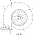
FIG. 3A is a top view of the turbine housing according to one embodiment, with the turbine housing including a wall and an exterior surface having a valve seat, and with the wall and the valve seat collectively defining a valve cavity; -
FIG. 3B is a top view of the turbine housing according to another embodiment, with the turbine housing including the wall and an interior surface having the valve seat, and with the wall and the valve seat collectively defining the valve cavity. -
FIG. 4 is a side view of a valve assembly according to one embodiment, with the valve assembly including a first valve member that is engageable with the wall of the turbine housing and a second valve member that is engageable with the valve seat of the exterior surface of the turbine housing; -
FIG. 5 is a front view of the valve assembly ofFIG. 4 , showing an outer contour of the first valve member that is rotationally symmetric about an axis; -
FIG. 6 is a cross-sectional view of the valve assembly ofFIG. 4 , showing the first valve member extending along the axis between a first end and a second end spaced from the first end, with the first valve member defining a valve interior between the first and second ends, and with a biasing member disposed in the valve interior; -
FIG. 7 is cross-sectional view of the valve assembly according to another embodiment; -
FIG. 8 is a cross-sectional view of the valve assembly ofFIG. 4 and the turbine housing ofFIG. 3A , with the first valve member in a first position where the first valve member is disposed in the valve cavity and adjacent the wall of the turbine housing, and with the second valve member in a closed position where a base of the second valve member is engaged with the valve seat of the turbine housing; -
FIG. 9 is a cross-sectional view of the valve assembly ofFIG. 4 and the turbine housing ofFIG. 3A , with the first valve member in a second position where the first valve member is disposed in the valve cavity and spaced from the wall of the turbine housing, and with the second valve member in the closed position; -
FIG. 10 is a cross-sectional view of the valve assembly ofFIG. 4 and the turbine housing ofFIG. 3A , with the first valve member in a third position where the first valve member is disposed outside of the valve cavity, and with the second valve member in an open position where the base of the second valve member is disengaged with the valve seat; -
FIG. 11 is an isometric view of the first valve member of the valve assembly according to another embodiment, with the outer contour of the first valve member including a protrusion configured to engage the wall of the turbine housing; and -
FIG. 12 is a side view of the first valve member ofFIG. 11 . - With reference to the Figures, wherein like numerals indicate like parts throughout the several views, a schematic representation of a
dual volute turbocharger 20 for receiving exhaust gas from an internal combustion engine 22 (shown inFIG. 2 ) and delivering compressed air to theinternal combustion engine 22 is shown inFIG. 1 . Although not required, thedual volute turbocharger 20 is typically used in passenger and commercial automotive applications. However, it is to be appreciated that thedual volute turbocharger 20 may be used in non-automotive applications such as heavy equipment applications, non-automotive diesel engine applications, non-automotive motor applications, and the like. As shown inFIGS. 1-3B , thedual volute turbocharger 20 includes aturbine housing 24 and aturbine wheel 26 disposed in theturbine housing 24. - With reference again to
FIG. 1 , thedual volute turbocharger 20 typically includes aturbocharger shaft 28, acompressor wheel 30, acompressor housing 34, and a bearinghousing 36. During operation of thedual volute turbocharger 20, theturbine wheel 26 receives exhaust gas from theinternal combustion engine 22 which causes theturbine wheel 26 to rotate. Theturbocharger shaft 28 is coupled to and rotatable by theturbine wheel 26. Thecompressor wheel 30 is coupled to theturbocharger shaft 28 and is rotatable by theturbocharger shaft 28 for delivering compressed air to theinternal combustion engine 22. Thecompressor wheel 30 is disposed in thecompressor housing 34. The bearinghousing 36 extends about theturbocharger shaft 28 between theturbine wheel 26 and thecompressor wheel 30. Thedual volute turbocharger 20 also typically includesbearings 36 disposed about theturbocharger shaft 28 and in the bearinghousing 36 for rotatably supporting theturbocharger shaft 28. - As shown in
FIG. 2 , theturbine housing 24 includes aninterior surface 38 that defines aturbine housing interior 40. Theturbine housing interior 40 is adapted to receive theturbine wheel 26. Theinterior surface 38 also defines afirst volute 42, and asecond volute 44. The first andsecond volutes internal combustion engine 22 and theturbine housing interior 40 for delivering exhaust gas from theinternal combustion engine 22 to theturbine housing interior 40. As shown inFIGS. 1 ,3A and3B , theinterior surface 38 also defines aturbine housing outlet 46. Theturbine housing outlet 46 is in fluid communication with theturbine housing interior 40 for discharging exhaust gas from theturbine housing interior 40. With reference again toFIG. 2 , theturbine housing 24 also includes awall 48 separating thefirst volute 42 from thesecond volute 44. Theturbine housing 24 may be comprised of any suitable metal or plastic. Typically, theturbine housing 24 is comprised of metal. - As shown in
FIGS. 3A and3B , theturbine housing 24 further includes avalve seat 52. Typically, thevalve seat 52 has as circular configuration, as shown inFIGS. 3A and3B . However, it is to be appreciated that thevalve seat 52 may have any configuration suitable for receiving avalve assembly 54 that will be described in greater detail below. Thewall 48 and thevalve seat 52 collectively define avalve cavity 56. Thevalve seat 52 may be included on anexterior surface 50 of theturbine housing 24, as shown inFIG. 3A . Alternatively, thevalve seat 52 may be included on theinterior surface 38 of theturbine housing 24, as shown inFIG. 3B . - With reference again to
FIG. 2 , theinternal combustion engine 22 includes a plurality ofcylinders 58. In the illustrated embodiment, the internal combustion engine includes fourcylinders 58. However, it is to be appreciated that theinternal combustion engine 22 may include any number ofcylinders 58. For example, theinternal combustion engine 22 may include twocylinders 58, fourcylinders 58, sixcylinders 58, eightcylinders 58, ormore cylinders 58. Theinternal combustion engine 22 may have a V-engine configuration, a flat/boxer engine configuration, a W-engine configuration, an inline engine configuration, and the like. In the illustrated embodiment, theinternal combustion engine 22 has an inline engine configuration. Theinternal combustion engine 22 includes a first group ofcylinders 60 and a second group ofcylinders 62. The first and second groups ofcylinders cylinders 58 that are included in theinternal combustion engine 22. For example, when theinternal combustion engine 22 includes fourcylinders 58 as shown inFIG. 2 , the first group ofcylinders 60 includes two of thecylinders 58 and the second group ofcylinders 62 includes the other two of thecylinders 58. The first and second groups ofcylinders cylinders cylinders 60 is different from timing of the exhaust stroke of the second group ofcylinders 62 such that the first and second groups ofcylinders - With continued reference to
FIG. 2 , typically the first group ofcylinders 60 are in fluid communication with thefirst volute 42 and the second group ofcylinders 62 are in communication with thesecond volute 44. In this manner, pulses of exhaust gas from the first and second groups ofcylinders second volutes turbine housing interior 40, where the pulses of exhaust gas rotate theturbine wheel 26. - With reference to
FIGS. 4-7 , thedual volute turbocharger 20 also includes avalve assembly 54 for controlling exhaust gas flow from the first andsecond volutes turbine housing interior 40. - As shown in
FIG. 4 , thevalve assembly 54 includes afirst valve member 64. Thefirst valve member 64 is engageable with thewall 48 of theturbine housing 24. With reference toFIG. 6 , thefirst valve member 64 is disposed about an axis A between afirst end 66 adapted to be proximal to thewall 48 of theturbine housing 24 and asecond end 68 spaced from thefirst end 66 and adapted to be distal to thewall 48 of theturbine housing 24. Thefirst valve member 64 defines avalve interior 70 between the first and second ends 66, 68. Thefirst valve member 64 may be comprised of any suitable metal. With reference toFIGS. 8-10 , thefirst valve member 64 is movable between a first position, a second position, and a third position. - As shown in
FIG. 8 , when thefirst valve member 64 is in the first position, thefirst valve member 64 is disposed in thevalve cavity 56 and adjacent thewall 48 of theturbine housing 24 for restricting exhaust gas from flowing between the first andsecond volutes wall 48, as shown inFIG. 8 . Specifically, thefirst end 66 of thefirst valve member 64 is engaged with thewall 48 of theturbine housing 24. However, it is to be appreciated that thefirst valve member 64 may not be engaged with thewall 48 in the first position, and instead thefirst valve member 64 may be in close proximity to thewall 48. Accordingly, when thefirst valve member 64 is in the first position, pulses of exhaust gas from the first group ofcylinders 60 flow through thefirst volute 42 to theturbine housing interior 40 and are restricted from flowing to thesecond volute 44 because thefirst valve member 64 is adjacent thewall 48 of theturbine housing 24. Similarly, pulses of exhaust gas from the second group ofcylinders 62 flow through thesecond volute 44 to theturbine housing interior 40 and are restricted flowing tofirst volute 42 because thefirst valve member 64 is adjacent thewall 48 of theturbine housing 24. - As shown in
FIG. 9 , when thefirst valve member 64 is in the second position, thefirst valve member 64 is disposed in thevalve cavity 56 and spaced from thewall 48 of theturbine housing 24 for allowing exhaust gas to flow between the first andsecond volutes second volutes gap 71 between thefirst valve member 64 and thewall 48 because thefirst valve member 64 is spaced from thewall 48. Accordingly, when thefirst valve member 64 is in the second position, as shown inFIG. 9 , pulses of exhaust gas from the first group ofcylinders 60 flow through thefirst volute 42 to theturbine housing interior 40 and also through thefirst volute 42 to thesecond volute 44 and then to theturbine housing interior 40. Similarly, pulses of exhaust gas from the second group ofcylinders 62 flow through thefirst volute 42 to theturbine housing interior 40 and also through thefirst volute 42 to thesecond volute 44 and then to theturbine housing interior 40. - As shown in
FIG. 10 , when the first valve member is in the third position, thefirst valve member 64 is disposed outside of thevalve cavity 56 for allowing exhaust gas from the first andsecond volutes turbine housing interior 40. Specifically, exhaust gas can flow from both of the first andsecond volutes valve cavity 56 to an environment outside of theturbine housing 24, bypassing theturbine housing interior 40, because thefirst valve member 64 is not disposed in thevalve cavity 56. Accordingly, when thefirst valve member 64 is in the third position, pulses of exhaust gas from the first and second groups ofcylinders second volutes valve cavity 56 to an environment outside of theturbine housing 24, thereby bypassing theturbine housing interior 40. - With reference again to
FIGS. 4 and6 , thevalve assembly 54 also includes avalve shaft 72. As shown inFIG. 6 , thevalve shaft 72 is partially disposed in thevalve interior 70. Thevalve shaft 72 is coupled to and extends from thefirst end 66 of thefirst valve member 64. Thevalve shaft 72 extends from thefirst end 66 of thefirst valve member 64 in a direction ofsecond end 68 of thefirst valve member 64 to afree end 74 of thevalve shaft 72 that is not disposed in thevalve interior 70. In the illustrated embodiment, thevalve shaft 72 is integral with thefirst end 66 of thefirst valve member 64. However, it is to be appreciated that thevalve shaft 72 may not be integral with thefirst end 66 of thefirst valve member 64. Instead, thevalve shaft 72 shaft may be coupled to thefirst end 66 of thefirst valve member 64 in any suitable manner, such as via fasteners, weldments, riveting, etc. Typically, thevalve shaft 72 extends from thefirst end 66 of thefirst valve member 64 along the axis A and is movable along the axis A for moving thefirst valve member 64 between the first, second, and third positions. Although not required, typically thevalve shaft 72 has a cylindrical configuration. However, it is to be appreciated that thevalve shaft 72 may have any configuration suitable for moving thefirst valve member 64 between the first, second, and third positions, such as a rectangular prism configuration. Thevalve shaft 72 may be comprised of any suitable metal or plastic. - With reference again to
FIG. 4 , thevalve assembly 54 further includes asecond valve member 76. Thesecond valve member 76 is engageable with thevalve seat 52. With reference toFIG. 6 , thesecond valve member 76 has a base 78 coupled to and disposed about thevalve shaft 72. Although not required, typically thebase 78 has a circular configuration, particularly when thevalve seat 52 also has a circular configuration. However, it is to be appreciated that the base 78 may have any configuration suitable for engaging thevalve seat 52. Thesecond valve member 76 also has aprojection 80 extending from thebase 78 and about thevalve shaft 72. Theprojection 80 extends from the base 78 into thevalve interior 70 of thefirst valve member 64. In the illustrated embodiment, theprojection 80 has a cylindrical configuration. However, it is to be appreciated that theprojection 80 may have any suitable configuration. Although not required, typically theprojection 80 is integral with thebase 78. However, it is to be appreciated that theprojection 80 may not be integral with thebase 78 and instead theprojection 80 may be coupled to the base 78 in any suitable manner. In the illustrated embodiment, thebase 78 and theprojection 80 collectively define achannel 82 that thevalve shaft 72 extends through. Thesecond valve member 76 may be comprised of any suitable metal or plastic. As shown inFIGS. 8-10 , thesecond valve member 76 is movable between a closed position and an open position. - With reference to
FIGS. 8 and 9 , when thesecond valve member 76 is in the closed position, thebase 78 is engaged with thevalve seat 52 of theexterior surface 50 of theturbine housing 24 for restricting exhaust gas from the first andsecond volutes turbine housing interior 40. When thesecond valve member 76 is in the closed position, exhaust gas flows through the first and/orsecond volutes turbine housing interior 40 and is restricted from bypassing theturbine housing interior 40 because thebase 78 of thesecond valve member 76 is engaged with thevalve seat 52. - As shown in
FIGS. 8 and 9 , when thesecond valve member 76 is in the closed position, thevalve shaft 72 is movable along the axis A relative to thesecond valve member 76 in order to move thefirst valve member 64 between the first and second positions. Moreover, thesecond end 68 of thefirst valve member 64 may abut thebase 78 of thesecond valve member 76, as shown inFIG. 9 , when thefirst valve member 64 is in the second position and thesecond valve member 76 is in the closed position. - With reference again to
FIG. 8 , when thesecond valve member 76 is in the closed position and thefirst valve member 64 is in the first position, pulses of exhaust gas from the first and second groups ofcylinders second volutes turbine housing interior 40 and are restricted from flowing between the first andsecond volutes turbine housing interior 40. Exhaust gas is restricted from flowing between the first andsecond volutes first valve member 64 is adjacent thewall 48, and exhaust gas is restricted from bypassing theturbine housing interior 40 because thebase 78 of thesecond valve member 76 is engaged with thevalve seat 52. - With reference to
FIG. 9 , when thesecond valve member 76 is in the closed position andfirst valve member 64 is in the second position, exhaust gas can flow between the first andsecond volutes first valve member 64 is spaced from thewall 48. However, exhaust gas is restricted from bypassing theturbine housing interior 40 because thebase 78 of thesecond valve member 76 is engaged with thevalve seat 52. - With reference to
FIG. 10 , when thesecond valve member 76 is in the open position, thebase 78 is disengaged with thevalve seat 52 of theexterior surface 50 of theturbine housing 24 for allowing exhaust gas from the first andsecond volutes turbine housing interior 40. Because thebase 78 of thesecond valve member 76 is disengaged from thevalve seat 52, pulses of exhaust gas from the first and second groups ofcylinders second volutes valve cavity 56 to the environment outside of theturbine housing 24, thereby bypassing theturbine housing interior 40. - Typically, the
first valve member 64 is in the third position when thesecond valve member 76 is in the closed position, as shown inFIG. 10 . However, it is to be appreciated that thefirst valve member 64 may be in the first and/or second position when thesecond valve member 76 is in the open position. In such embodiments, portions of the pulses of exhaust gas from the first and second groups ofcylinders turbine housing interior 40 whereas other portions of the pulses of exhaust gas flow through the first and/orsecond volutes turbine housing interior 40. - With reference again to
FIG. 6 , thevalve assembly 54 may further include a biasingmember 84. When present, the biasingmember 84 is disposed in thevalve interior 70 and about thevalve shaft 72. The biasingmember 84 is configured to bias thefirst valve member 64 into one of the first and second positions when thesecond valve member 76 is in the closed position. With reference toFIG. 9 , in the illustrated embodiment, the biasingmember 84 biases thefirst valve member 64 into the second position when thesecond valve member 76 is in the closed position. As such, a force must be applied to thevalve shaft 72 strong enough to overcome a corresponding force of the biasingmember 84 in order to move thevalve shaft 72 so that thefirst valve member 64 is moved from the second position to the first position. Similarly, when the biasingmember 84 biases thefirst valve member 64 into the first position when thesecond valve member 76 is in the closed position, a force must be applied to thevalve shaft 72 strong enough to overcome a corresponding force of the biasingmember 84 in order to move thevalve shaft 72 so that thefirst valve member 64 is moved from the first position to the second position. The biasingmember 84 may reduce noise, vibration, and harshness (NVH) characteristics associated with thevalve assembly 54 during operation of thedual volute turbocharger 20. - Exposure of the biasing
member 84 to exhaust gas increases wear of the biasingmember 84, thereby reducing efficiency of thedual volute turbocharger 20. Specifically, exposure of the biasingmember 84 to exhaust gas leads to relaxation and reduction in force capability, material degradation, oxidation, and/or corrosion of the biasing member 84 (i.e., wear of the biasing member). Moreover, exposure of the biasingmember 84 to exhaust gas can ultimately lead to failure of the biasingmember 84 due to the wear. Because the biasingmember 84 is disposed in thevalve interior 70, the biasingmember 84 is shielded/protected from exhaust gas during operation of thedual volute turbocharger 20. In other words, exposure of the biasingmember 84 to exhaust gas during operation of thedual volute turbocharger 20 is reduced as compared to other components of thevalve assembly 54, such as the first andsecond valve members member 84 is also reduced, thereby increasing the efficiency of thedual volute turbocharger 20 and increasing lifetime of thedual volute turbocharger 20. - Typically, the biasing
member 84 is chosen from a cupped spring, a curved spring, a wave spring, and a coil spring. In some embodiments, as shown inFIGS. 6-10 , the biasingmember 84 is acoil spring 84. However, it is to be appreciated that the biasingmember 84 may be any biasingmember 84 suitable for biasing thefirst valve member 64 into one of the first and second positions when thesecond valve member 76 is in the closed position. - With reference again to
FIG. 6 , in some embodiments, the biasingmember 84 is disposed about theprojection 80 of thesecond valve member 76. In such embodiments, the biasingmember 84 is disposed about both thevalve shaft 72 and theprojection 80. However, it is to be appreciated that the biasingmember 84 may be disposed aboutvalve shaft 72 and not about theprojection 80, as shown inFIG. 7 . - With continued reference to
FIG. 6 , thesecond valve member 76 may further include alip 86 extending radially from theprojection 80 with respect to the axis A. Typically, thelip 86 is disposed in thevalve interior 70 and is spaced from thebase 78 of thesecond valve member 76, as shown in the illustrated embodiment. The configuration of thelip 86 is not particularly limited. For example, thelip 86 may have a circular configuration, a rectangular configuration, and the like. In the illustrated embodiment, thelip 86 is integral with theprojection 80. However, it is to be appreciated that thelip 86 may not be integral with theprojection 80 and instead may be coupled to theprojection 80 in any suitable manner. - When the
second valve member 76 includes theprojection 80, the biasingmember 84 is typically disposed between and in contact with thelip 86 of thesecond valve member 76 and thesecond end 68 of thefirst valve member 64, as shown inFIG. 6 . In such embodiments, the second biasingmember 84 is disposed about both thevalve shaft 72 and theprojection 80. Moreover, in such embodiments, the biasingmember 84 typically biases thefirst valve member 64 into the second position when thesecond valve member 76 is in the closed position. - In other embodiments, the biasing
member 84 is disposed between and in contact with thelip 86 of thesecond valve member 76 and thefirst end 66 of thefirst valve member 64, as shown inFIG. 7 . In such embodiments, the biasingmember 84 is disposed about thevalve shaft 72 but not theprojection 80 of thesecond valve member 76. Furthermore, in such embodiments, the biasingmember 84 typically biases thefirst valve member 64 into the first position when thesecond valve member 76 is in the closed position. Moreover, in such embodiments, thesecond end 68 of thefirst valve member 64 may abut thelip 86 of thesecond valve member 76 when thefirst valve member 64 is in the first position. - With reference again to
FIG. 6 , in some embodiments, thefirst valve member 64 has aninner contour 88 facing thevalve interior 70 and anouter contour 90 facing away from thevalve interior 70. In some embodiments, theouter contour 90 is configured to reduce wear of thevalve assembly 54. Specifically, theouter contour 90 may reduce wear by reducing contact stress between thevalve assembly 54 and theturbine housing 24. - During operation of the
dual volute turbocharger 20, exhaust gas flows through the first andsecond volutes first valve member 64. Over time, force exerted by exhaust gas on thefirst valve member 64 causes wear of thefirst valve member 64, thevalve shaft 72, and thesecond valve member 76. Specifically, force exerted by exhaust gas on thefirst valve member 64 causes thefirst valve member 64, thevalve shaft 72, and thesecond valve member 76 to vibrate against each other and also causes the first andsecond valve members turbine housing 24. These repeated vibrations cause wear of the first andsecond valve members valve shaft 72, thereby decreasing efficiency of thedual volute turbocharger 20 and ultimately leading to failure of thevalve assembly 54. Wear of the first andsecond valve members valve shaft 72 also decreases efficiency of thedual volute turbocharger 20 because the wear results in a loss of control over the amount of exhaust bypassing theturbine housing interior 40 and also a loss of control over turbocharger boost levels. When theouter contour 90 is configured to reduce wear of thevalve assembly 54, theouter contour 90 reduces force exerted by exhaust gas on thefirst valve member 64, thereby reducing wear of the first andsecond valve members valve shaft 72 because vibrations of the first andsecond valve members valve shaft 72 against each other and/or theturbine housing 24 are reduced. This reduced wear results in increased efficiency of thedual volute turbocharger 20, and increased lifetime of thedual volute turbocharger 20. - As shown in
FIGS. 4-6 ,11 , and12 , in some embodiments, theouter contour 90 is cup-shaped for reducing wear of thevalve assembly 54. However, it is to be appreciated that theouter contour 90 may have any suitable configuration for reducing wear of thevalve assembly 54. Although not required, theouter contour 90 may abut theturbine housing 24 when thefirst valve member 64 is in the first and second positions, as shown inFIGS. 8 and 9 . - With reference to
FIGS. 11 and12 , when theouter contour 90 is cup-shaped, the outer contour may include aprotrusion 92. Theprotrusion 92 extends axially away from thevalve shaft 72 and is configured to be engageable thewall 48 of theturbine housing 24 when thefirst valve member 64 is in the first position. When present, theprotrusion 92 is located at thefirst end 66 of thefirst valve member 64. Typically, theprotrusion 92 has a configuration that is complementary with thewall 48 of theturbine housing 24 for engaging thewall 48 such that theprotrusion 92 prevents exhaust gas from flowing between the first andsecond volutes first valve member 64 is in the first position. In this manner, theouter contour 90 can be configured to reduce wear of thevalve assembly 54 while also ensuring that exhaust gas does not flow between the first andsecond volutes first valve member 64 is in the first position. - In some embodiments, the
outer contour 90 of thefirst valve member 64 is rotationally symmetric about the axis A, as shown inFIG. 5 . When theouter contour 90 is rotationally symmetric about the axis A, typically theouter contour 90 is cup-shaped. However, it is to be appreciated that theouter contour 90 may be cup-shaped and not rotationally symmetric about the axis A, as shown inFIGS. 11 and12 . Moreover, it is to be appreciated that theouter contour 90 may be rotationally symmetric about the axis A and not cup-shaped. - With reference again to
FIG. 12 , theouter contour 90 may further includesidewalls 94. When present, thesidewalls 94 extend from thesecond end 68 of thefirst valve member 64 and along the axis A in the direction of thesecond end 66. Typically, the sidewalls are parallel, or substantially parallel, with the axis A. With reference toFIGS. 11 and12 , in the illustrated embodiment, theouter contour 90 includes twosidewalls 94. However, it is to be appreciated that theouter contour 90 may include any suitable number of sidewalls. For example, theouter contour 90 may include three, four, or even more sidewalls 94. Thesidewalls 94 alter exhaust gas flow around thefirst valve member 64, particularly when thefirst valve member 64 is in the first and second positions, and may further reduce wear on thevalve assembly 54 in addition to allowing a greater volume of exhaust gas to bypass theturbine housing interior 40 when thefirst valve member 64 is in the third position. When present, thesidewalls 94 are spaced circumferentially from each other with respect to the axis A. Typically, thesidewalls 94 are spaced equally and circumferentially from each other with respect to the axis A, as shown inFIG. 12 . Alternatively, thesidewalls 94 may not be spaced equally and circumferentially from each other. Instead, thesidewalls 94 may be spaced circumferentially from each other at an angle of from about 140° to 180° with respect to the axis A. With reference toFIG. 11 , in the illustrated embodiment, thesidewalls 94 are circumferentially spaced from each other at an angle of 180° with respect to the axis A. - With continued reference to
FIG. 11 , when thesidewalls 94 are present, theouter contour 90 typically includesfirst surface portions 95. Each of thefirst surface portions 95 extends about the axis A from one of thesidewalls 94 to anadjacent sidewall 94, as shown inFIG. 12 . Typically, thefirst surface portions 95 have an arcuate configuration. Although not required, typically the number offirst surface portions 95 included in theouter contour 90 is equal to thenumber sidewalls 94. When theprotrusion 92 and twofirst surface portions 95 are present, theprotrusion 92 may extend between the twosurface portions 95, as shown inFIG. 11 . Thefirst surface portions 95 are spaced circumferentially from each other with respect to the axis A. Typically, thefirst surface portions 95 are spaced equally and circumferentially from each other with respect to the axis A. - The
outer contour 90 may further includesecond surface portions 96, as shown inFIGS. 11 and12 . When present, thesecond surface portions 96 further reduce wear of thevalve assembly 54 by altering exhaust gas flow around thefirst valve member 64, particularly when thefirst valve member 64 is in the first, second, and third positions. Thesecond surface portions 96 may have an arcuate configuration. With reference toFIGS. 11 and12 , when theprojection 92 and thesidewalls 94 are included in theouter contour 90 of thefirst valve member 64, eachsecond surface portion 96 extends between one of thesidewalls 94 to theprojection 92. In this manner, theouter contour 90 is further optimized for reducing wear of thevalve assembly 54. - With reference again to
FIG. 6 , thesecond end 68 of thefirst valve member 64 may include acover 98 extending about the axis A. When thesecond end 68 includes thecover 98, thecover 98 is disposed about thevalve shaft 72. Moreover, when thecover 98 is present, thecover 98 and theinner contour 88 collectively define thevalve interior 70. During operation of thedual volute turbocharger 20, thecover 98 further reduces exposure of the biasingmember 84 to exhaust gas. Thecover 98 may be integral with thevalve member 64, as shown inFIG. 6 . However, it is to be appreciated that thecover 98 may not be integral with thefirst valve member 64 and instead may be coupled to thefirst valve member 64 in any suitable manner. - With continued reference to
FIG. 6 , in the illustrated embodiment, the biasingmember 84 is disposed between and in contact with thelip 86 of thesecond valve member 76 and thecover 98 of thefirst valve member 64. However, it is to be appreciated that the biasingmember 84 is not necessarily in contact with thecover 98 when thecover 98 is present, as shown inFIG. 7 . - The
valve assembly 54 typically includes an actuator for moving thevalve shaft 72 along the axis A to move the first valve member between the first, second, and third positions and thesecond valve member 76 between the closed and open positions. The actuator is operably coupled to thevalve shaft 72. The actuator may be an electric actuator or a pneumatic actuator. The actuator is configured to move thefirst valve member 64 to the first position, the second position, the third position, and any other position between the first, second, and third positions. Moreover, the actuator is configured to move thesecond valve member 76 to the closed position, the open position, and any position between the closed and open positions. - The
valve assembly 54 may be operably coupled to thedual volute turbocharger 20 in any suitable manner such that thevalve assembly 54 is able to control exhaust gas flow from the first andsecond volutes turbine housing interior 40. For example, thevalve assembly 54 may be operable coupled to theturbine housing 24, thecompressor housing 32, and/or the bearinghousing 34. - During operation of the
internal combustion engine 22 and thedual volute turbocharger 20, thefirst valve member 64 is moved between the first, second, and third positions and thesecond valve member 76 between the open and closed positions based on operating conditions of theinternal combustion engine 22 and thedual volute turbocharger 20. When thefirst valve member 64 is in the first position and thesecond valve member 76 is in the closed position (FIG. 8 ), as pulses of exhaust gas flow from the first and second groups ofcylinders second volutes internal combustion engine 22. When the back pressure on theinternal combustion engine 22 meets or exceeds a particular threshold that is associated with deleteriously impacting theinternal combustion engine 22, thefirst valve member 64 is be moved to the second position while thesecond valve member 76 remains in the closed position (FIG. 9 ). This reduces the back pressure on theinternal combustion engine 22 to non-deleterious levels while also maintaining efficiency of thedual volute turbocharger 20 because the pulses of exhaust gas from each of the first and second groups ofcylinders second volutes turbine housing interior 40, where the pulses of exhaust gas rotate theturbine wheel 26. It is to be appreciated that thefirst valve member 64 may be moved to the second position, or to a position between the first and second positions, in order to reduce back pressure on theinternal combustion engine 22 while also maintaining efficiency of thedual volute turbocharger 20. - During operation of the
internal combustion engine 22 and thedual volute turbocharger 20, the pulses of exhaust gas from each of the first and second groups ofcylinders internal combustion engine 22 large enough that the back pressure cannot be reduced to non-deleterious levels by moving thefirst valve member 64 between the first and second positions while thesecond valve member 76 is in the closed position. In such instances, thesecond valve member 76 is moved from the closed position to the open position (FIG. 10 ). As described above, typically thefirst valve member 64 is in the third position when thesecond valve member 76 is in the open position. Moving thesecond valve member 76 into the open position allows exhaust gas from the first and second groups ofcylinders turbine housing interior 40 to an environment outside of theturbine housing 24, thereby ensuring the back pressure on theinternal combustion engine 22 is reduced to non-deleterious levels. It is to be appreciated that thesecond valve member 76 may be moved to the open position, or to a position between the closed and open positions, in order ensure that the back pressure on theinternal combustion engine 22 is reduced to non-deleterious levels. - One method of controlling the
valve assembly 54 for thedual volute turbocharger 20 is described inU.S. Provisional Patent Application No. 62/806,396 - The invention has been described in an illustrative manner, and it is to be understood that the terminology which has been used is intended to be in the nature of words of description rather than of limitation. Many modifications and variations of the present invention are possible in light of the above teachings, and the invention may be practiced otherwise than as specifically described.
Claims (12)
- A valve assembly for controlling exhaust gas flow to a turbine housing interior of a dual volute turbocharger, said valve assembly comprising:a first valve member disposed about and extending along an axis between a first end and a second end spaced from said first end, with said first valve member defining a valve interior between said first and seconds ends, and with said first valve member movable between a first position, a second position, and a third position for controlling exhaust gas flow to the turbine housing interior of the dual volute turbocharger;a valve shaft partially disposed in said valve interior and coupled to and extending from said first end of said first valve member, with said valve shaft extending along said axis from said first end of said first valve member for moving said first valve member between said first, second, and third positions;a second valve member having a base coupled to and disposed about said valve shaft and a projection extending from said base and about said valve shaft into said valve interior, with said second valve member movable between a closed position and an open position for controlling exhaust gas flow to the turbine housing interior of the dual volute turbocharger; anda biasing member disposed in said valve interior and about said valve shaft, with said biasing member configured to bias said first valve member into one of said first and second positions when said second valve member is in said closed position.
- The valve assembly as set forth in claim 1, wherein said biasing member is chosen from a cupped spring, a curved spring, a wave spring, and a coil spring.
- The valve assembly as set forth in claim 1, wherein said biasing member is disposed about said projection of said second valve member.
- The valve assembly as set forth in claim 3, wherein said second valve member further comprises a lip extending radially from said projection with respect to said axis.
- The valve assembly as set forth in claim 4, wherein said biasing member is disposed between and in contact with said lip of said second valve member and said second end of said first valve member.
- The valve assembly as set forth in claim 1, wherein said first valve member has an outer contour that is cup-shaped.
- The valve assembly as set forth in claim 1, wherein said biasing member is configured to bias said first valve member into said second position when said second valve member is in said closed position.
- The valve assembly as set forth in claim 1, wherein said biasing member is configured to bias said first valve member into said second position when said second valve member is in said closed position
- A dual volute turbocharger comprising said valve assembly of any one of claims 1 - 8, wherein said dual volute turbocharger comprises:a turbine housing comprising,
an interior surface defining,a turbine housing interior adapted to receive a turbine wheel,a first volute adapted for fluid communication with the internal combustion engine and said turbine housing interior for delivering exhaust gas from the internal combustion engine to said turbine housing interior,a second volute adapted for fluid communication with the internal combustion engine and said turbine housing interior for delivering exhaust gas from the internal combustion engine to said turbine housing interior, anda turbine housing outlet in fluid communication with said turbine housing interior for discharging exhaust gas from said turbine housing interior,a wall separating said first volute from said second volute, anda valve seat, wherein said wall and said valve seat collectively define a valve cavity;wherein said valve assembly is configured to control exhaust gas flow from said first and second volutes to said turbine housing interior;wherein said first valve member is engageable with said wall of said turbine housing;wherein said first end of said first valve member is adapted to be proximal to said wall of said turbine housing and said second end is adapted to be distal said wall of said turbine housing;wherein, when in said first position, said first valve member is disposed in said valve cavity and adjacent said wall of said turbine housing for restricting exhaust gas from flowing between said first and second volutes;wherein, when in said second position, said first valve member is disposed in said valve cavity and spaced from said wall of said turbine housing for allowing exhaust gas to flow between said first and second volutes;wherein, when in said third position, said first valve member is disposed outside of said valve cavity for allowing exhaust gas from said first and second volutes to bypass said turbine housing interior; andwherein said second valve member is engageable with said valve seat, with said base being engaged with said valve seat of said turbine housing for restricting exhaust gas from said first and second volutes from bypassing said turbine housing interior when said second valve member is in said closed position, and with said base being disengaged with said valve seat of said turbine housing for allowing exhaust gas from said first and second volutes to bypass said turbine housing interior when said second valve member is in said open position. - The dual volute turbocharger as set forth in claim 9, wherein said outer contour of said first valve member is configured to reduce wear of said valve assembly.
- The dual volute turbocharger as set forth in claim 10, wherein said outer contour of said first valve member includes a protrusion configured to be engageable with said wall of said turbine housing when said first valve member is in said first position.
- The dual volute turbocharger as set forth in claim 10, wherein said outer contour of said first valve member is rotationally symmetric about said axis.
Applications Claiming Priority (2)
| Application Number | Priority Date | Filing Date | Title |
|---|---|---|---|
| US201962806434P | 2019-02-15 | 2019-02-15 | |
| US202062962321P | 2020-01-17 | 2020-01-17 |
Publications (2)
| Publication Number | Publication Date |
|---|---|
| EP3696386A1 true EP3696386A1 (en) | 2020-08-19 |
| EP3696386B1 EP3696386B1 (en) | 2021-10-20 |
Family
ID=69581969
Family Applications (1)
| Application Number | Title | Priority Date | Filing Date |
|---|---|---|---|
| EP20157039.7A Active EP3696386B1 (en) | 2019-02-15 | 2020-02-12 | Valve assembly for a dual volute turbocharger and dual volute turbocharger including the same |
Country Status (3)
| Country | Link |
|---|---|
| US (1) | US11408333B2 (en) |
| EP (1) | EP3696386B1 (en) |
| CN (1) | CN212272384U (en) |
Families Citing this family (1)
| Publication number | Priority date | Publication date | Assignee | Title |
|---|---|---|---|---|
| DE102020134770A1 (en) * | 2020-12-22 | 2022-06-23 | Borgwarner Inc. | VALVE ASSEMBLY FOR MULTIPLE ENTRY TURBINE |
Citations (4)
| Publication number | Priority date | Publication date | Assignee | Title |
|---|---|---|---|---|
| WO2007060831A1 (en) * | 2005-11-24 | 2007-05-31 | Toyota Jidosha Kabushiki Kaisha | Exhaust passage changeover valve |
| DE102010008411A1 (en) * | 2010-02-18 | 2011-08-18 | Daimler AG, 70327 | Turbine for an exhaust gas turbocharger |
| WO2016094268A1 (en) * | 2014-12-12 | 2016-06-16 | Borgwarner Inc. | Mono or dual coaxial slider valve for controlling a twin scroll turbocharger |
| DE202018104140U1 (en) * | 2017-07-21 | 2018-07-25 | Ihi Charging Systems International Gmbh | Regulating device for an exhaust gas turbocharger |
Family Cites Families (34)
| Publication number | Priority date | Publication date | Assignee | Title |
|---|---|---|---|---|
| US3423926A (en) | 1966-08-31 | 1969-01-28 | Garrett Corp | Turbocharger control arrangement |
| SE510714C2 (en) | 1997-10-09 | 1999-06-14 | Volvo Ab | Turbocharged internal combustion engine |
| DE19826355A1 (en) | 1998-06-12 | 1999-12-16 | Daimler Chrysler Ag | Arrangement for controlling an exhaust gas turbocharger turbine of an internal combustion engine |
| DE10152804B4 (en) | 2001-10-25 | 2016-05-12 | Daimler Ag | Internal combustion engine with an exhaust gas turbocharger and an exhaust gas recirculation device |
| US6983596B2 (en) | 2001-11-02 | 2006-01-10 | Borgwarner Inc. | Controlled turbocharger with integrated bypass |
| US6969048B2 (en) | 2003-06-17 | 2005-11-29 | Siemens Aktiengesellschaft | Valve element for supplementary control valve device |
| DE102004034070A1 (en) | 2004-07-15 | 2006-02-09 | Daimlerchrysler Ag | Internal combustion engine with an exhaust gas turbocharger |
| US20070119170A1 (en) | 2005-11-29 | 2007-05-31 | Patrick Masson | Non-rotating turbocharger waste gate valve |
| DE102006046826B4 (en) | 2006-10-02 | 2017-07-13 | Bosch Mahle Turbo Systems Gmbh & Co. Kg | charging |
| DE102006060907A1 (en) | 2006-12-20 | 2008-06-26 | Mp-Engineering Gmbh | Turbocharger has controlling unit that has rotary rolling slider that is supported in turbine housing, which has cross opening that is based on longitudinal axis, and is excentricaly arranged for longitudinal axis |
| JP2009024584A (en) | 2007-07-19 | 2009-02-05 | Toyota Motor Corp | Exhaust passage control device for internal combustion engine |
| DE202009018979U1 (en) | 2008-10-01 | 2015-02-09 | Borgwarner Inc. | Wastegate with variable flow |
| JP2011179401A (en) | 2010-03-01 | 2011-09-15 | Mitsubishi Heavy Ind Ltd | Waste gate valve device |
| CN102400776B (en) | 2010-09-09 | 2014-10-08 | 株式会社电装 | Exhaust gas control apparatus for engine |
| CN104364492B (en) | 2012-06-21 | 2017-10-13 | 博格华纳公司 | Exhaust gas turbocharger |
| US8984880B2 (en) | 2012-09-13 | 2015-03-24 | Honeywell International Inc. | Turbine wastegate |
| US9200532B2 (en) | 2012-09-13 | 2015-12-01 | Honeywell International Inc. | Turbine wastegate |
| DE102012111558A1 (en) | 2012-11-29 | 2014-06-05 | Firma IHI Charging Systems International GmbH | Regulating device for an exhaust gas guide section of a turbine |
| DE102013002894B4 (en) | 2013-02-20 | 2018-12-20 | Daimler Ag | Turbine for an exhaust gas turbocharger |
| US9359939B2 (en) | 2013-02-20 | 2016-06-07 | Ford Global Technologies, Llc | Supercharged internal combustion engine with two-channel turbine and method |
| DE102013209049A1 (en) | 2013-05-15 | 2014-11-20 | Bayerische Motoren Werke Aktiengesellschaft | Turbocharger arrangement |
| US10006342B2 (en) | 2014-02-20 | 2018-06-26 | Ford Global Technologies, Llc | Exhaust flow valve for twin-scroll turbine and operating methods thereof |
| US9810143B2 (en) | 2015-01-16 | 2017-11-07 | Ford Global Technologies, Llc | Exhaust control valve branch communication and wastegate |
| DE102015001763A1 (en) | 2015-02-11 | 2016-08-11 | GM Global Technology Operations LLC (n. d. Ges. d. Staates Delaware) | Wastegate valve actuator |
| DE102015209044A1 (en) | 2015-05-18 | 2016-11-24 | Bosch Mahle Turbo Systems Gmbh & Co. Kg | turbocharger |
| DE102016204076A1 (en) | 2015-05-18 | 2016-11-24 | Bosch Mahle Turbo Systems Gmbh & Co. Kg | turbocharger |
| DE102015011256B4 (en) | 2015-08-25 | 2025-08-14 | Mercedes-Benz Group AG | Turbine for an exhaust gas turbocharger |
| DE102015016586A1 (en) | 2015-12-19 | 2017-06-22 | Daimler Ag | Valve device for a turbine of an exhaust gas turbocharger |
| DE102015122351B4 (en) | 2015-12-21 | 2025-04-30 | Ihi Charging Systems International Gmbh | Exhaust gas guide section for an exhaust gas turbocharger and method for operating an exhaust gas turbocharger |
| JP6394621B2 (en) | 2016-02-19 | 2018-09-26 | マツダ株式会社 | Engine supercharger |
| DE102016103145A1 (en) | 2016-02-23 | 2017-08-24 | Ihi Charging Systems International Gmbh | Regulating device for an exhaust gas turbocharger |
| DE102016006719A1 (en) * | 2016-06-01 | 2017-02-09 | Daimler Ag | Turbine for an exhaust gas turbocharger |
| US10677150B2 (en) | 2017-05-11 | 2020-06-09 | Garrett Transportation I Inc. | Rotatable valve for turbocharger system with plural volute members |
| DE202018101705U1 (en) | 2018-03-27 | 2018-04-20 | Borgwarner Inc. | Valve arrangement for multi-flow turbine |
-
2020
- 2020-02-12 US US16/788,927 patent/US11408333B2/en active Active
- 2020-02-12 EP EP20157039.7A patent/EP3696386B1/en active Active
- 2020-02-14 CN CN202020169346.5U patent/CN212272384U/en active Active
Patent Citations (4)
| Publication number | Priority date | Publication date | Assignee | Title |
|---|---|---|---|---|
| WO2007060831A1 (en) * | 2005-11-24 | 2007-05-31 | Toyota Jidosha Kabushiki Kaisha | Exhaust passage changeover valve |
| DE102010008411A1 (en) * | 2010-02-18 | 2011-08-18 | Daimler AG, 70327 | Turbine for an exhaust gas turbocharger |
| WO2016094268A1 (en) * | 2014-12-12 | 2016-06-16 | Borgwarner Inc. | Mono or dual coaxial slider valve for controlling a twin scroll turbocharger |
| DE202018104140U1 (en) * | 2017-07-21 | 2018-07-25 | Ihi Charging Systems International Gmbh | Regulating device for an exhaust gas turbocharger |
Also Published As
| Publication number | Publication date |
|---|---|
| US20200263599A1 (en) | 2020-08-20 |
| US11408333B2 (en) | 2022-08-09 |
| EP3696386B1 (en) | 2021-10-20 |
| CN212272384U (en) | 2021-01-01 |
Similar Documents
| Publication | Publication Date | Title |
|---|---|---|
| US7506508B2 (en) | Compressor in an exhaust gas turbocharger of an internal combustion engine and method for operating the compressor | |
| CN103732879B (en) | Exhaust turbocharger with ball-tipped wastegate valve and strain-relieved crank arm | |
| US7426831B2 (en) | Turbo charging system | |
| KR20190073485A (en) | Valve device | |
| US20130305711A1 (en) | Bleed valve of an exhaust gas turbocharger | |
| US20140099191A1 (en) | Turbine for an exhaust gas turbocharger | |
| US10533491B1 (en) | Connecting assembly and turbocharger including the connecting assembly | |
| US11028765B2 (en) | Dual volute turbocharger and system including the same | |
| CN112805460B (en) | Turbocharger with actuator-actuated regulating device and transmission element with one-piece component body | |
| CN211230615U (en) | Turbocharger and system for vehicle | |
| CN103620184B (en) | Multistage supercharging system | |
| US11408333B2 (en) | Valve assembly for a dual volute turbocharger and dual volute turbocharger including the same | |
| US20170051765A1 (en) | Pneumatic actuator with piston having an extended lip | |
| JP2007146687A (en) | Exhaust passage switching valve | |
| US10711690B2 (en) | Wastegate assembly and turbocharger including the same | |
| US10018164B2 (en) | Gas compressor pressure relief noise reduction | |
| US11732601B2 (en) | Variable turbine geometry assembly | |
| US11408331B2 (en) | Wastegate assembly and turbocharger including the same | |
| US11371423B2 (en) | Wastegate assembly | |
| US11834955B1 (en) | Variable turbine geometry assembly | |
| CN112460045A (en) | Compressor and method for operating a compressor | |
| CN220337488U (en) | Valve, twin-volute turbine and exhaust turbocharger | |
| KR100774336B1 (en) | Turbocharger system of diesel engine | |
| JP2014020318A (en) | Variable nozzle control device and variable geometry turbocharger | |
| JP7191466B2 (en) | internal combustion engine silencer |
Legal Events
| Date | Code | Title | Description |
|---|---|---|---|
| PUAI | Public reference made under article 153(3) epc to a published international application that has entered the european phase |
Free format text: ORIGINAL CODE: 0009012 |
|
| STAA | Information on the status of an ep patent application or granted ep patent |
Free format text: STATUS: THE APPLICATION HAS BEEN PUBLISHED |
|
| AK | Designated contracting states |
Kind code of ref document: A1 Designated state(s): AL AT BE BG CH CY CZ DE DK EE ES FI FR GB GR HR HU IE IS IT LI LT LU LV MC MK MT NL NO PL PT RO RS SE SI SK SM TR |
|
| AX | Request for extension of the european patent |
Extension state: BA ME |
|
| STAA | Information on the status of an ep patent application or granted ep patent |
Free format text: STATUS: REQUEST FOR EXAMINATION WAS MADE |
|
| 17P | Request for examination filed |
Effective date: 20210210 |
|
| RBV | Designated contracting states (corrected) |
Designated state(s): AL AT BE BG CH CY CZ DE DK EE ES FI FR GB GR HR HU IE IS IT LI LT LU LV MC MK MT NL NO PL PT RO RS SE SI SK SM TR |
|
| GRAP | Despatch of communication of intention to grant a patent |
Free format text: ORIGINAL CODE: EPIDOSNIGR1 |
|
| STAA | Information on the status of an ep patent application or granted ep patent |
Free format text: STATUS: GRANT OF PATENT IS INTENDED |
|
| RIC1 | Information provided on ipc code assigned before grant |
Ipc: F02B 37/12 20060101ALN20210409BHEP Ipc: F16K 11/10 20060101ALI20210409BHEP Ipc: F16K 11/04 20060101ALI20210409BHEP Ipc: F01D 17/14 20060101ALI20210409BHEP Ipc: F01D 17/10 20060101ALI20210409BHEP Ipc: F01D 17/08 20060101ALI20210409BHEP Ipc: F02C 9/18 20060101ALI20210409BHEP Ipc: F01D 9/02 20060101ALI20210409BHEP Ipc: F02B 37/22 20060101ALI20210409BHEP Ipc: F02B 37/18 20060101ALI20210409BHEP Ipc: F02B 37/02 20060101AFI20210409BHEP |
|
| INTG | Intention to grant announced |
Effective date: 20210507 |
|
| RAP3 | Party data changed (applicant data changed or rights of an application transferred) |
Owner name: BORGWARNER INC. |
|
| GRAS | Grant fee paid |
Free format text: ORIGINAL CODE: EPIDOSNIGR3 |
|
| GRAA | (expected) grant |
Free format text: ORIGINAL CODE: 0009210 |
|
| STAA | Information on the status of an ep patent application or granted ep patent |
Free format text: STATUS: THE PATENT HAS BEEN GRANTED |
|
| AK | Designated contracting states |
Kind code of ref document: B1 Designated state(s): AL AT BE BG CH CY CZ DE DK EE ES FI FR GB GR HR HU IE IS IT LI LT LU LV MC MK MT NL NO PL PT RO RS SE SI SK SM TR |
|
| REG | Reference to a national code |
Ref country code: GB Ref legal event code: FG4D |
|
| REG | Reference to a national code |
Ref country code: CH Ref legal event code: EP |
|
| REG | Reference to a national code |
Ref country code: IE Ref legal event code: FG4D |
|
| REG | Reference to a national code |
Ref country code: DE Ref legal event code: R096 Ref document number: 602020000750 Country of ref document: DE |
|
| REG | Reference to a national code |
Ref country code: AT Ref legal event code: REF Ref document number: 1440134 Country of ref document: AT Kind code of ref document: T Effective date: 20211115 |
|
| REG | Reference to a national code |
Ref country code: LT Ref legal event code: MG9D |
|
| REG | Reference to a national code |
Ref country code: NL Ref legal event code: MP Effective date: 20211020 |
|
| REG | Reference to a national code |
Ref country code: AT Ref legal event code: MK05 Ref document number: 1440134 Country of ref document: AT Kind code of ref document: T Effective date: 20211020 |
|
| PG25 | Lapsed in a contracting state [announced via postgrant information from national office to epo] |
Ref country code: RS Free format text: LAPSE BECAUSE OF FAILURE TO SUBMIT A TRANSLATION OF THE DESCRIPTION OR TO PAY THE FEE WITHIN THE PRESCRIBED TIME-LIMIT Effective date: 20211020 Ref country code: LT Free format text: LAPSE BECAUSE OF FAILURE TO SUBMIT A TRANSLATION OF THE DESCRIPTION OR TO PAY THE FEE WITHIN THE PRESCRIBED TIME-LIMIT Effective date: 20211020 Ref country code: FI Free format text: LAPSE BECAUSE OF FAILURE TO SUBMIT A TRANSLATION OF THE DESCRIPTION OR TO PAY THE FEE WITHIN THE PRESCRIBED TIME-LIMIT Effective date: 20211020 Ref country code: BG Free format text: LAPSE BECAUSE OF FAILURE TO SUBMIT A TRANSLATION OF THE DESCRIPTION OR TO PAY THE FEE WITHIN THE PRESCRIBED TIME-LIMIT Effective date: 20220120 Ref country code: AT Free format text: LAPSE BECAUSE OF FAILURE TO SUBMIT A TRANSLATION OF THE DESCRIPTION OR TO PAY THE FEE WITHIN THE PRESCRIBED TIME-LIMIT Effective date: 20211020 |
|
| PG25 | Lapsed in a contracting state [announced via postgrant information from national office to epo] |
Ref country code: IS Free format text: LAPSE BECAUSE OF FAILURE TO SUBMIT A TRANSLATION OF THE DESCRIPTION OR TO PAY THE FEE WITHIN THE PRESCRIBED TIME-LIMIT Effective date: 20220220 Ref country code: SE Free format text: LAPSE BECAUSE OF FAILURE TO SUBMIT A TRANSLATION OF THE DESCRIPTION OR TO PAY THE FEE WITHIN THE PRESCRIBED TIME-LIMIT Effective date: 20211020 Ref country code: PT Free format text: LAPSE BECAUSE OF FAILURE TO SUBMIT A TRANSLATION OF THE DESCRIPTION OR TO PAY THE FEE WITHIN THE PRESCRIBED TIME-LIMIT Effective date: 20220221 Ref country code: PL Free format text: LAPSE BECAUSE OF FAILURE TO SUBMIT A TRANSLATION OF THE DESCRIPTION OR TO PAY THE FEE WITHIN THE PRESCRIBED TIME-LIMIT Effective date: 20211020 Ref country code: NO Free format text: LAPSE BECAUSE OF FAILURE TO SUBMIT A TRANSLATION OF THE DESCRIPTION OR TO PAY THE FEE WITHIN THE PRESCRIBED TIME-LIMIT Effective date: 20220120 Ref country code: NL Free format text: LAPSE BECAUSE OF FAILURE TO SUBMIT A TRANSLATION OF THE DESCRIPTION OR TO PAY THE FEE WITHIN THE PRESCRIBED TIME-LIMIT Effective date: 20211020 Ref country code: LV Free format text: LAPSE BECAUSE OF FAILURE TO SUBMIT A TRANSLATION OF THE DESCRIPTION OR TO PAY THE FEE WITHIN THE PRESCRIBED TIME-LIMIT Effective date: 20211020 Ref country code: HR Free format text: LAPSE BECAUSE OF FAILURE TO SUBMIT A TRANSLATION OF THE DESCRIPTION OR TO PAY THE FEE WITHIN THE PRESCRIBED TIME-LIMIT Effective date: 20211020 Ref country code: GR Free format text: LAPSE BECAUSE OF FAILURE TO SUBMIT A TRANSLATION OF THE DESCRIPTION OR TO PAY THE FEE WITHIN THE PRESCRIBED TIME-LIMIT Effective date: 20220121 Ref country code: ES Free format text: LAPSE BECAUSE OF FAILURE TO SUBMIT A TRANSLATION OF THE DESCRIPTION OR TO PAY THE FEE WITHIN THE PRESCRIBED TIME-LIMIT Effective date: 20211020 |
|
| REG | Reference to a national code |
Ref country code: DE Ref legal event code: R097 Ref document number: 602020000750 Country of ref document: DE |
|
| PG25 | Lapsed in a contracting state [announced via postgrant information from national office to epo] |
Ref country code: SM Free format text: LAPSE BECAUSE OF FAILURE TO SUBMIT A TRANSLATION OF THE DESCRIPTION OR TO PAY THE FEE WITHIN THE PRESCRIBED TIME-LIMIT Effective date: 20211020 Ref country code: SK Free format text: LAPSE BECAUSE OF FAILURE TO SUBMIT A TRANSLATION OF THE DESCRIPTION OR TO PAY THE FEE WITHIN THE PRESCRIBED TIME-LIMIT Effective date: 20211020 Ref country code: RO Free format text: LAPSE BECAUSE OF FAILURE TO SUBMIT A TRANSLATION OF THE DESCRIPTION OR TO PAY THE FEE WITHIN THE PRESCRIBED TIME-LIMIT Effective date: 20211020 Ref country code: EE Free format text: LAPSE BECAUSE OF FAILURE TO SUBMIT A TRANSLATION OF THE DESCRIPTION OR TO PAY THE FEE WITHIN THE PRESCRIBED TIME-LIMIT Effective date: 20211020 Ref country code: DK Free format text: LAPSE BECAUSE OF FAILURE TO SUBMIT A TRANSLATION OF THE DESCRIPTION OR TO PAY THE FEE WITHIN THE PRESCRIBED TIME-LIMIT Effective date: 20211020 Ref country code: CZ Free format text: LAPSE BECAUSE OF FAILURE TO SUBMIT A TRANSLATION OF THE DESCRIPTION OR TO PAY THE FEE WITHIN THE PRESCRIBED TIME-LIMIT Effective date: 20211020 |
|
| PLBE | No opposition filed within time limit |
Free format text: ORIGINAL CODE: 0009261 |
|
| STAA | Information on the status of an ep patent application or granted ep patent |
Free format text: STATUS: NO OPPOSITION FILED WITHIN TIME LIMIT |
|
| 26N | No opposition filed |
Effective date: 20220721 |
|
| PG25 | Lapsed in a contracting state [announced via postgrant information from national office to epo] |
Ref country code: MC Free format text: LAPSE BECAUSE OF FAILURE TO SUBMIT A TRANSLATION OF THE DESCRIPTION OR TO PAY THE FEE WITHIN THE PRESCRIBED TIME-LIMIT Effective date: 20211020 |
|
| REG | Reference to a national code |
Ref country code: BE Ref legal event code: MM Effective date: 20220228 |
|
| PG25 | Lapsed in a contracting state [announced via postgrant information from national office to epo] |
Ref country code: LU Free format text: LAPSE BECAUSE OF NON-PAYMENT OF DUE FEES Effective date: 20220212 Ref country code: AL Free format text: LAPSE BECAUSE OF FAILURE TO SUBMIT A TRANSLATION OF THE DESCRIPTION OR TO PAY THE FEE WITHIN THE PRESCRIBED TIME-LIMIT Effective date: 20211020 |
|
| PG25 | Lapsed in a contracting state [announced via postgrant information from national office to epo] |
Ref country code: SI Free format text: LAPSE BECAUSE OF FAILURE TO SUBMIT A TRANSLATION OF THE DESCRIPTION OR TO PAY THE FEE WITHIN THE PRESCRIBED TIME-LIMIT Effective date: 20211020 |
|
| PG25 | Lapsed in a contracting state [announced via postgrant information from national office to epo] |
Ref country code: FR Free format text: LAPSE BECAUSE OF NON-PAYMENT OF DUE FEES Effective date: 20220228 |
|
| PG25 | Lapsed in a contracting state [announced via postgrant information from national office to epo] |
Ref country code: IE Free format text: LAPSE BECAUSE OF NON-PAYMENT OF DUE FEES Effective date: 20220212 |
|
| PG25 | Lapsed in a contracting state [announced via postgrant information from national office to epo] |
Ref country code: BE Free format text: LAPSE BECAUSE OF NON-PAYMENT OF DUE FEES Effective date: 20220228 |
|
| PG25 | Lapsed in a contracting state [announced via postgrant information from national office to epo] |
Ref country code: IT Free format text: LAPSE BECAUSE OF FAILURE TO SUBMIT A TRANSLATION OF THE DESCRIPTION OR TO PAY THE FEE WITHIN THE PRESCRIBED TIME-LIMIT Effective date: 20211020 |
|
| P01 | Opt-out of the competence of the unified patent court (upc) registered |
Effective date: 20230327 |
|
| REG | Reference to a national code |
Ref country code: CH Ref legal event code: PL |
|
| PG25 | Lapsed in a contracting state [announced via postgrant information from national office to epo] |
Ref country code: LI Free format text: LAPSE BECAUSE OF NON-PAYMENT OF DUE FEES Effective date: 20230228 Ref country code: CH Free format text: LAPSE BECAUSE OF NON-PAYMENT OF DUE FEES Effective date: 20230228 |
|
| PG25 | Lapsed in a contracting state [announced via postgrant information from national office to epo] |
Ref country code: MK Free format text: LAPSE BECAUSE OF FAILURE TO SUBMIT A TRANSLATION OF THE DESCRIPTION OR TO PAY THE FEE WITHIN THE PRESCRIBED TIME-LIMIT Effective date: 20211020 Ref country code: CY Free format text: LAPSE BECAUSE OF FAILURE TO SUBMIT A TRANSLATION OF THE DESCRIPTION OR TO PAY THE FEE WITHIN THE PRESCRIBED TIME-LIMIT Effective date: 20211020 |
|
| PG25 | Lapsed in a contracting state [announced via postgrant information from national office to epo] |
Ref country code: HU Free format text: LAPSE BECAUSE OF FAILURE TO SUBMIT A TRANSLATION OF THE DESCRIPTION OR TO PAY THE FEE WITHIN THE PRESCRIBED TIME-LIMIT; INVALID AB INITIO Effective date: 20200212 |
|
| PG25 | Lapsed in a contracting state [announced via postgrant information from national office to epo] |
Ref country code: MT Free format text: LAPSE BECAUSE OF FAILURE TO SUBMIT A TRANSLATION OF THE DESCRIPTION OR TO PAY THE FEE WITHIN THE PRESCRIBED TIME-LIMIT Effective date: 20211020 |
|
| GBPC | Gb: european patent ceased through non-payment of renewal fee |
Effective date: 20240212 |
|
| PG25 | Lapsed in a contracting state [announced via postgrant information from national office to epo] |
Ref country code: GB Free format text: LAPSE BECAUSE OF NON-PAYMENT OF DUE FEES Effective date: 20240212 |
|
| PG25 | Lapsed in a contracting state [announced via postgrant information from national office to epo] |
Ref country code: GB Free format text: LAPSE BECAUSE OF NON-PAYMENT OF DUE FEES Effective date: 20240212 |
|
| PGFP | Annual fee paid to national office [announced via postgrant information from national office to epo] |
Ref country code: DE Payment date: 20250109 Year of fee payment: 6 |
|
| PG25 | Lapsed in a contracting state [announced via postgrant information from national office to epo] |
Ref country code: TR Free format text: LAPSE BECAUSE OF FAILURE TO SUBMIT A TRANSLATION OF THE DESCRIPTION OR TO PAY THE FEE WITHIN THE PRESCRIBED TIME-LIMIT Effective date: 20211020 |