EP3696359A1 - Door closer assembly - Google Patents
Door closer assembly Download PDFInfo
- Publication number
- EP3696359A1 EP3696359A1 EP19157877.2A EP19157877A EP3696359A1 EP 3696359 A1 EP3696359 A1 EP 3696359A1 EP 19157877 A EP19157877 A EP 19157877A EP 3696359 A1 EP3696359 A1 EP 3696359A1
- Authority
- EP
- European Patent Office
- Prior art keywords
- cam element
- door closer
- closer assembly
- door
- assembly according
- Prior art date
- Legal status (The legal status is an assumption and is not a legal conclusion. Google has not performed a legal analysis and makes no representation as to the accuracy of the status listed.)
- Withdrawn
Links
- 238000013022 venting Methods 0.000 claims description 13
- 238000007789 sealing Methods 0.000 claims description 8
- 238000004891 communication Methods 0.000 claims description 4
- 238000013016 damping Methods 0.000 description 4
- 230000007423 decrease Effects 0.000 description 4
- 238000000034 method Methods 0.000 description 4
- 230000005540 biological transmission Effects 0.000 description 2
- 238000011084 recovery Methods 0.000 description 2
- 238000009423 ventilation Methods 0.000 description 2
- 230000001419 dependent effect Effects 0.000 description 1
- 238000009795 derivation Methods 0.000 description 1
- 238000003780 insertion Methods 0.000 description 1
- 230000037431 insertion Effects 0.000 description 1
- 238000009434 installation Methods 0.000 description 1
- 230000001788 irregular Effects 0.000 description 1
- 238000004519 manufacturing process Methods 0.000 description 1
- 238000012986 modification Methods 0.000 description 1
- 230000004048 modification Effects 0.000 description 1
Images



Classifications
-
- E—FIXED CONSTRUCTIONS
- E05—LOCKS; KEYS; WINDOW OR DOOR FITTINGS; SAFES
- E05F—DEVICES FOR MOVING WINGS INTO OPEN OR CLOSED POSITION; CHECKS FOR WINGS; WING FITTINGS NOT OTHERWISE PROVIDED FOR, CONCERNED WITH THE FUNCTIONING OF THE WING
- E05F3/00—Closers or openers with braking devices, e.g. checks; Construction of pneumatic or liquid braking devices
- E05F3/04—Closers or openers with braking devices, e.g. checks; Construction of pneumatic or liquid braking devices with liquid piston brakes
- E05F3/10—Closers or openers with braking devices, e.g. checks; Construction of pneumatic or liquid braking devices with liquid piston brakes with a spring, other than a torsion spring, and a piston, the axes of which are the same or lie in the same direction
- E05F3/104—Closers or openers with braking devices, e.g. checks; Construction of pneumatic or liquid braking devices with liquid piston brakes with a spring, other than a torsion spring, and a piston, the axes of which are the same or lie in the same direction with cam-and-slide transmission between driving shaft and piston within the closer housing
-
- E—FIXED CONSTRUCTIONS
- E05—LOCKS; KEYS; WINDOW OR DOOR FITTINGS; SAFES
- E05F—DEVICES FOR MOVING WINGS INTO OPEN OR CLOSED POSITION; CHECKS FOR WINGS; WING FITTINGS NOT OTHERWISE PROVIDED FOR, CONCERNED WITH THE FUNCTIONING OF THE WING
- E05F3/00—Closers or openers with braking devices, e.g. checks; Construction of pneumatic or liquid braking devices
- E05F3/22—Additional arrangements for closers, e.g. for holding the wing in opened or other position
- E05F2003/228—Arrangements where the end of the closer arm is sliding in a track
-
- E—FIXED CONSTRUCTIONS
- E05—LOCKS; KEYS; WINDOW OR DOOR FITTINGS; SAFES
- E05Y—INDEXING SCHEME ASSOCIATED WITH SUBCLASSES E05D AND E05F, RELATING TO CONSTRUCTION ELEMENTS, ELECTRIC CONTROL, POWER SUPPLY, POWER SIGNAL OR TRANSMISSION, USER INTERFACES, MOUNTING OR COUPLING, DETAILS, ACCESSORIES, AUXILIARY OPERATIONS NOT OTHERWISE PROVIDED FOR, APPLICATION THEREOF
- E05Y2201/00—Constructional elements; Accessories therefor
- E05Y2201/60—Suspension or transmission members; Accessories therefor
- E05Y2201/622—Suspension or transmission members elements
- E05Y2201/624—Arms
-
- E—FIXED CONSTRUCTIONS
- E05—LOCKS; KEYS; WINDOW OR DOOR FITTINGS; SAFES
- E05Y—INDEXING SCHEME ASSOCIATED WITH SUBCLASSES E05D AND E05F, RELATING TO CONSTRUCTION ELEMENTS, ELECTRIC CONTROL, POWER SUPPLY, POWER SIGNAL OR TRANSMISSION, USER INTERFACES, MOUNTING OR COUPLING, DETAILS, ACCESSORIES, AUXILIARY OPERATIONS NOT OTHERWISE PROVIDED FOR, APPLICATION THEREOF
- E05Y2201/00—Constructional elements; Accessories therefor
- E05Y2201/60—Suspension or transmission members; Accessories therefor
- E05Y2201/622—Suspension or transmission members elements
- E05Y2201/638—Cams; Ramps
-
- E—FIXED CONSTRUCTIONS
- E05—LOCKS; KEYS; WINDOW OR DOOR FITTINGS; SAFES
- E05Y—INDEXING SCHEME ASSOCIATED WITH SUBCLASSES E05D AND E05F, RELATING TO CONSTRUCTION ELEMENTS, ELECTRIC CONTROL, POWER SUPPLY, POWER SIGNAL OR TRANSMISSION, USER INTERFACES, MOUNTING OR COUPLING, DETAILS, ACCESSORIES, AUXILIARY OPERATIONS NOT OTHERWISE PROVIDED FOR, APPLICATION THEREOF
- E05Y2201/00—Constructional elements; Accessories therefor
- E05Y2201/60—Suspension or transmission members; Accessories therefor
- E05Y2201/622—Suspension or transmission members elements
- E05Y2201/682—Pins
-
- E—FIXED CONSTRUCTIONS
- E05—LOCKS; KEYS; WINDOW OR DOOR FITTINGS; SAFES
- E05Y—INDEXING SCHEME ASSOCIATED WITH SUBCLASSES E05D AND E05F, RELATING TO CONSTRUCTION ELEMENTS, ELECTRIC CONTROL, POWER SUPPLY, POWER SIGNAL OR TRANSMISSION, USER INTERFACES, MOUNTING OR COUPLING, DETAILS, ACCESSORIES, AUXILIARY OPERATIONS NOT OTHERWISE PROVIDED FOR, APPLICATION THEREOF
- E05Y2800/00—Details, accessories and auxiliary operations not otherwise provided for
- E05Y2800/26—Form or shape
- E05Y2800/292—Form or shape having apertures
- E05Y2800/296—Slots
Definitions
- This invention is related to the field of door closing systems, and more particularly, to the door closing systems which use a cam to actuate against a spring.
- Automated door closing systems are used to make a door close automatically when it has been opened. These systems are usually based on a spring which stores energy when the door is being opened and exerts a return force to close the door.
- this return force is proportional to the opening angle of the door, so the door may be difficult to be opened by some groups of people such children and elderly, as the opening torque maybe too high.
- an additional hold-open device is required, so that the user needs to manually push the door to its hold-open angle and then engage the hold-open function.
- the invention provides a door closer assembly comprising
- This door closer provides a door closing torque which ensures proper closing of the door at the first half of opening angle and also makes the door swing towards the full open angle at the second half of the door opening angle.
- the arrangement of its elements makes the door closing torque being highest around initial door opening and gradually dropping to zero force at the middle of opening range, continuing to drop to negative torque such that the door will swing to its hold open angle by itself.
- This door closer also provides a hold-open functionality, since the spring presses the pin against the slot so that a positive torque is required to bring the door back to the original position.
- the first cam element has a symmetric profile.
- This profile is easier to manufacture and install, and works advantageously well with the rest of the element of the door closer assembly.
- the first cam element has a profile comprising a first portion which is a circumference arc having an arc centre and a second portion with a curved line, wherein all the points of the curved line are farther from the arc centre than the points of the circumference arc, wherein the pin protrudes from the second portion of the profile.
- the door closer assembly further comprises a second cam element which is arranged to receive the pin, the protruding portion being arranged between the first cam element and the second cam element so that the pin protrudes from the first cam element, then goes through the slot of the protruding portion and is received by the second cam element.
- This second cam element provides a stronger and more robust mechanical structure, thus being able to endure a harder operation environment.
- the protruding portion is substantially plane, with a first face and a second face, so that the first cam element faces the first face and the second cam element faces the second face.
- This arrangement saves some space and allows a better support between the cam elements and the protruding portion.
- the door closer assembly further comprises a second rod which is coaxial with the first rod, the second rod being solidly attached to the second cam element and arranged to rotate coaxially with the second cam element.
- These two rods forms the two ends of the whole transmission system, which comprises the two rods, the cam elements and the pin.
- the torque is transmitted from the door bar and moves the transmission system as a crankshaft.
- the door closer assembly further comprises a first bearing arranged around the first rod and a second bearing arranged around the second rod.
- the path of the slot comprises a continuous curved portion oriented towards the plate portion.
- This curved portion creates a free swing zone, so that when the roller pin goes into the curved portion, the effective arm is reduced, due to the fact that a smaller movement is requested at the abutment element.
- the curved portion is an arc of circumference with a radius which is equal to the distance between the pin and the rotation axis.
- This particular shape of the curved portion achieves a zero-torque zone.
- the door closer assembly further comprises a housing with two sealing caps.
- This housing provides a support for all the elements and improves the installation conditions.
- the door closer assembly further comprises a venting valve which provides a venting communication to a region between the abutment element and one of the sealing caps.
- This venting valve creates a hydraulic damping, which is useful to provide soft closing and backcheck.
- Figure 1 shows a perspective exploded view of a door closer assembly according to the invention.
- This door closer assembly comprises
- the abutment element 2 comprises a plate portion 21, which is arranged in contact with the spring 1 and is intended to press or release the spring 1.
- This abutment element 2 also comprises a protruding portion 22 which protrudes from the plate portion 21.
- This protruding portion which is plane, comprises a slot 23.
- the first cam element 3 is arranged to rotate around a rotation axis, and comprises a pin 4 which is intended to be inserted in the slot 23 of the abutment element.
- This pin 4 protrudes from the first cam element 3 according to a protruding axis which is parallel to the rotation axis.
- the pin 4 is intended to be inserted in the slot 23 so that the movement of the first cam element 3 is transmitted by means of the pin 4 to the slot 23, so that the abutment element 2 may move linearly when the first cam element 3 rotates.
- the second cam element is arranged at the other side of the protruding element 2, to receive the pin 4, which has passed across the slot 23.
- the protruding portion 22 is therefore arranged between the first cam element 3 and the second cam element 7 so that the pin 4 protrudes from the first cam element 3, then goes through the slot 23 of the protruding portion 22 and is received by the second cam element 7.
- the protruding portion 22 is substantially plane, with a first face and a second face, so that the first cam element 3 faces the first face and the second cam element 7 faces the second face.
- first and second rods 5, 8, which are solidly attached to the first cam element 3 and to the second cam element 7 respectively. Both rods 5, 8 and cam elements 3, 7 are arranged to rotate coaxially all together.
- a pair of bearings 91, 92 are arranged around the rods 5, 8, so as to provide a smooth rotation movement of the assembly comprising the rods 5, 8 and the cam elements 3, 7, which are limited by the insertion in the housing 10.
- the first rod 5 is intended to be attached to a bar 6 which transmits a swinging movement of an opening and closing door to the door closer assembly.
- the bar 6 rotates when the door is being opened or closed, and transmits this rotation movement to the door closer assembly of the figure.
- the door closer assembly offers a feedback torque in response to this rotation movement, which affects to the force the user has to provide to open the door.
- the housing 10 is sealed by two sealing caps 11, 12, thus creating a closed region, which is open by a venting valve 13, which provides a venting communication to a region between the abutment element 2 and one of the sealing caps.
- the venting valve 13 thus provides a hydraulic damping, by the control of the venting communication. If the venting valve 13 is set to provide tight ventilation, the damping will be higher, and if the venting valve 13 is set to provide a loose ventilation, the damping will be lower.
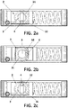
- Figures 2a to 2c shows top views of a first embodiment of a door closer assembly according to the invention, in three different positions.
- Figure 2a shows this door closer assembly in a first position, where the door is deemed to be closed. In this position, the torque is maximum, since the moment arm is maximum and the force, which is not maximum, is still high enough.
- the first cam element 3 has a profile comprising a first portion 31 which is a circumference arc having an arc centre and a second portion 32 with a curved line, wherein all the points of the curved line are farther from the arc centre than the points of the circumference arc.
- the pin 4 protrudes from the second portion 32 of this profile.
- Figure 2b shows this door closer assembly in a second position, where the bar angle is 90o.
- the moment arm decreases while the angle goes from 0o to 90o, as in this figure, so that when the pin 4 reaches the 90o position, the moment arm is 0, and hence the torque becomes 0 as well.
- Figure 2c shows this door closer assembly in a third position.
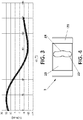
- Figure 3 shows a theoretical graphic representation of the torque T needed to move the door closer assembly of figures 2a to 2c with respect to the door angle ⁇ .
- the door angle does not correspond with the bar angle.
- the bar angle is the angle that the door bar forms with respect to the compressing direction of the spring, which corresponds to the rotation angle of the cam elements.
- the door angle is the angle that the door forms with respect to the closed position. Due to the shape of the door bar, the correspondence between these two angles may be selectively chosen. For this example, a bar angle of 90o corresponds to a door angle of 60o, and a bar angle of 180o corresponds to a door angle of 120o.
- the torque decreases for the first part of the opening process (which would correspond to a bar angle from 0o to 90o) and then becomes zero.
- the torque becomes negative, thus providing a hold-open functionality without any additional element.
- Figure 4 shows a detail of an abutment element 2 of a different embodiment of a door closer assembly according to the invention.
- a curved portion 24 oriented towards the plate portion 21.
- This curved portion has an impact in the torque response of the door closer, as will be shown below.
- Figures 5a to 5d shows top views of a second embodiment of a door closer assembly according to the invention, which comprises the abutment element 2 shown in the previous figure. Four different positions are illustrated in these figures.
- Figure 5a shows this door closer assembly in a first position, where the door is deemed to be closed. In this position, the torque is maximum, since the moment arm is maximum and the force, which is not maximum, is still high enough. The conditions at this position are substantially the same as in the embodiment shown in figure 2a .
- Figure 5b shows this door closer assembly in a second position, where the bar angle is close to 90o.
- the moment arm decreases while the angle goes from 0o to this position, since the moment arm decreases.
- the torque becomes 0, since the shape of the curved portion is a circumference arc which follows the trajectory of the pin without causing any movement in the abutment element 2.
- Figure 5c shows this door closer assembly in a third position.
- the pin is exiting the curved portion 24, but the abutment element remains in the same position as in figure 5b , due to the shape of this curved portion. As a consequence, the torque is still 0.
- Figure 5d shows this door closer assembly in a fourth position.
- Figure 6 shows a theoretical graphic representation of the torque needed to move the door closer assembly of figures 5a to 5d with respect to the door angle.
Landscapes
- Closing And Opening Devices For Wings, And Checks For Wings (AREA)
Abstract
This invention is related to a door closer assembly comprising a spring (1), an abutment element (2), a first cam element (3) and a first rod (5). The abutment element (2) is arranged to compress or release the spring (1), the abutment element (2) comprising a plate portion (21) arranged in contact with the spring (1) and a protruding portion (22) which protrudes from the plate portion (21) and comprises a slot (23). The first cam element (3) arranged to rotate around a rotation axis, the first cam element (3) comprising a pin (4) which protrudes from the first cam element (3) according to a protruding axis which is parallel to the rotation axis, the pin (4) being inserted inside the slot (23), the first cam element (3) having a partially circular profile. The first rod (5) solidly attached to the first cam element (3), arranged to rotate coaxially with the first cam element (3), the first rod (5) being intended to be attached to a bar (6) which transmits a swinging movement of an opening and closing door to the door closer assembly.
Description
- This invention is related to the field of door closing systems, and more particularly, to the door closing systems which use a cam to actuate against a spring.
- Automated door closing systems are used to make a door close automatically when it has been opened. These systems are usually based on a spring which stores energy when the door is being opened and exerts a return force to close the door.
- In some current door closers, those using a pinion and a rack, this return force is proportional to the opening angle of the door, so the door may be difficult to be opened by some groups of people such children and elderly, as the opening torque maybe too high.
- Further, if the door needs to be held open in a predetermined position, an additional hold-open device is required, so that the user needs to manually push the door to its hold-open angle and then engage the hold-open function.
- There are other door closers which use a cam which follow an irregular force against the spring, such as the one shown in document
US 5,417,013 A , which discloses a door closer having a slide rail linkage. The closer shaft has a first end projecting from the housing to be attached to the slide rail linkage, a cam for providing the closing movement of the door, and a second end which is mounted in a journal bearing disposed within the housing. This type of door closers follows a different torque-angle relation, but still has some drawbacks, since it also requires an additional hold-open device and the torque, despite being lower, may also be important. These devices require a secondary spring and a particular heart-shaped cam to operate, with a notch which is useful to beat the final latch force. This notch present in the cam may lead to cracks with continuous operation. - The invention provides an alternative solution for this problem by a door closer assembly according to
claim 1. Preferred embodiments of the invention are defined in dependent claims. - Unless otherwise defined, all terms (including technical and scientific terms) used herein are to be interpreted as is customary in the art. It will be further understood that terms in common usage should also be interpreted as is customary in the relevant art and not in an idealised or overly formal sense unless expressly so defined herein.
- In this text, the term "comprises" and its derivations (such as "comprising", etc.) should not be understood in an excluding sense, that is, these terms should not be interpreted as excluding the possibility that what is described and defined may include further elements, steps, etc.
- In a first inventive aspect, the invention provides a door closer assembly comprising
- a spring;
- an abutment element arranged to compress or release the spring, the abutment element comprising a plate portion arranged in contact with the spring and a protruding portion which protrudes from the plate portion and comprises a slot;
- a first cam element arranged to rotate around a rotation axis, the first cam element comprising a pin which protrudes from the first cam element according to a protruding axis which is parallel to the rotation axis, the pin being inserted inside the slot, the first cam element having a partially circular profile;
- a first rod solidly attached to the first cam element, arranged to rotate coaxially with the first cam element, the first rod being intended to be attached to a bar which transmits a swinging movement of an opening and closing door to the door closer assembly.
- This door closer provides a door closing torque which ensures proper closing of the door at the first half of opening angle and also makes the door swing towards the full open angle at the second half of the door opening angle. The arrangement of its elements makes the door closing torque being highest around initial door opening and gradually dropping to zero force at the middle of opening range, continuing to drop to negative torque such that the door will swing to its hold open angle by itself.
- This door closer also provides a hold-open functionality, since the spring presses the pin against the slot so that a positive torque is required to bring the door back to the original position.
- In some particular embodiments, the first cam element has a symmetric profile.
- This profile is easier to manufacture and install, and works advantageously well with the rest of the element of the door closer assembly.
- In some particular embodiments, the first cam element has a profile comprising a first portion which is a circumference arc having an arc centre and a second portion with a curved line, wherein all the points of the curved line are farther from the arc centre than the points of the circumference arc, wherein the pin protrudes from the second portion of the profile.
- The combination of this cam profile with the slot makes that the pin may run the path of the slot creating a torque-angle relation which includes a zero-torque zone.
- In some particular embodiments, the door closer assembly further comprises a second cam element which is arranged to receive the pin, the protruding portion being arranged between the first cam element and the second cam element so that the pin protrudes from the first cam element, then goes through the slot of the protruding portion and is received by the second cam element.
- This second cam element provides a stronger and more robust mechanical structure, thus being able to endure a harder operation environment.
- In some particular embodiments, the protruding portion is substantially plane, with a first face and a second face, so that the first cam element faces the first face and the second cam element faces the second face.
- This arrangement saves some space and allows a better support between the cam elements and the protruding portion.
- In some particular embodiments, the door closer assembly further comprises a second rod which is coaxial with the first rod, the second rod being solidly attached to the second cam element and arranged to rotate coaxially with the second cam element.
- These two rods forms the two ends of the whole transmission system, which comprises the two rods, the cam elements and the pin. The torque is transmitted from the door bar and moves the transmission system as a crankshaft.
- In some particular embodiments, the door closer assembly further comprises a first bearing arranged around the first rod and a second bearing arranged around the second rod.
- These two bearings provide a greater stability to the rods, thus making the system able to support a higher load.
- In some particular embodiments, the path of the slot comprises a continuous curved portion oriented towards the plate portion.
- This curved portion creates a free swing zone, so that when the roller pin goes into the curved portion, the effective arm is reduced, due to the fact that a smaller movement is requested at the abutment element.
- In some particular embodiments, the curved portion is an arc of circumference with a radius which is equal to the distance between the pin and the rotation axis.
- This particular shape of the curved portion achieves a zero-torque zone.
- In some particular embodiments, the door closer assembly further comprises a housing with two sealing caps.
- This housing provides a support for all the elements and improves the installation conditions.
- In some particular embodiments, the door closer assembly further comprises a venting valve which provides a venting communication to a region between the abutment element and one of the sealing caps.
- This venting valve creates a hydraulic damping, which is useful to provide soft closing and backcheck.
- To complete the description and in order to provide for a better understanding of the invention, a set of drawings is provided. Said drawings form an integral part of the description and illustrate an embodiment of the invention, which should not be interpreted as restricting the scope of the invention, but just as an example of how the invention can be carried out. The drawings comprise the following figures:
-
Figure 1 shows a perspective exploded view of a door closer assembly according to the invention. -
Figures 2a to 2c shows top views of a first embodiment of a door closer assembly according to the invention, in three different positions. -
Figure 3 shows a theoretical graphic representation of the torque needed to move the door closer assembly offigures 2a to 2c as a function of the door angle. -
Figure 4 shows a detail of an abutment element of a different embodiment of a door closer assembly according to the invention. -
Figures 5a to 5d shows top views of a second embodiment of a door closer assembly according to the invention, in four different positions. -
Figure 6 shows a theoretical graphic representation of the torque needed to move the door closer assembly offigures 5a to 5d with respect to the door angle. - Elements of the example embodiments are consistently denoted by the same reference numerals throughout the drawings and detailed description where appropriate:
- 1
- Spring
- 11, 12
- Sealing caps
- 13
- Venting valve
- 2
- Abutment element
- 21
- Plate portion of the abutment element
- 22
- Protruding portion of the abutment element
- 23
- Slot of the abutment element
- 3
- First cam
- 31
- First portion of the first cam profile
- 32
- Second portion of the first cam profile
- 4
- Pin
- 5
- First rod
- 6
- Door bar
- 7
- Second cam
- 8
- Second rod
- 91
- First bearing
- 92
- Second bearing
- The example embodiments are described in sufficient detail to enable those of ordinary skill in the art to embody and implement the systems and processes herein described. It is important to understand that embodiments can be provided in many alternate forms and should not be construed as limited to the examples set forth herein.
- Accordingly, while embodiment can be modified in various ways and take on various alternative forms, specific embodiments thereof are shown in the drawings and described in detail below as examples. There is no intent to limit to the particular forms disclosed. On the contrary, all modifications, equivalents, and alternatives falling within the scope of the appended claims should be included.
-
Figure 1 shows a perspective exploded view of a door closer assembly according to the invention. - This door closer assembly comprises
- a
spring 1; - an
abutment element 2 arranged to compress or release thespring 1, - a
first cam element 3; and - a
first rod 5 solidly attached to thefirst cam element 3; - a second cam element 7;
- a
second rod 8 solidly attached to the second cam element 7; - a pair of
bearings - a
housing 10; - a pair of sealing
caps - a venting
valve 13. - The
abutment element 2 comprises aplate portion 21, which is arranged in contact with thespring 1 and is intended to press or release thespring 1. Thisabutment element 2 also comprises a protrudingportion 22 which protrudes from theplate portion 21. This protruding portion, which is plane, comprises aslot 23. - The
first cam element 3 is arranged to rotate around a rotation axis, and comprises apin 4 which is intended to be inserted in theslot 23 of the abutment element. Thispin 4 protrudes from thefirst cam element 3 according to a protruding axis which is parallel to the rotation axis. Thepin 4 is intended to be inserted in theslot 23 so that the movement of thefirst cam element 3 is transmitted by means of thepin 4 to theslot 23, so that theabutment element 2 may move linearly when thefirst cam element 3 rotates. - The second cam element is arranged at the other side of the
protruding element 2, to receive thepin 4, which has passed across theslot 23. The protrudingportion 22 is therefore arranged between thefirst cam element 3 and the second cam element 7 so that thepin 4 protrudes from thefirst cam element 3, then goes through theslot 23 of the protrudingportion 22 and is received by the second cam element 7. The protrudingportion 22 is substantially plane, with a first face and a second face, so that thefirst cam element 3 faces the first face and the second cam element 7 faces the second face. - There are first and
second rods first cam element 3 and to the second cam element 7 respectively. Bothrods cam elements 3, 7 are arranged to rotate coaxially all together. - A pair of
bearings rods rods cam elements 3, 7, which are limited by the insertion in thehousing 10. - The
first rod 5 is intended to be attached to abar 6 which transmits a swinging movement of an opening and closing door to the door closer assembly. Thebar 6 rotates when the door is being opened or closed, and transmits this rotation movement to the door closer assembly of the figure. The door closer assembly offers a feedback torque in response to this rotation movement, which affects to the force the user has to provide to open the door. - The
housing 10 is sealed by two sealingcaps valve 13, which provides a venting communication to a region between theabutment element 2 and one of the sealing caps. The ventingvalve 13 thus provides a hydraulic damping, by the control of the venting communication. If the ventingvalve 13 is set to provide tight ventilation, the damping will be higher, and if the ventingvalve 13 is set to provide a loose ventilation, the damping will be lower. -
Figures 2a to 2c shows top views of a first embodiment of a door closer assembly according to the invention, in three different positions. -
Figure 2a shows this door closer assembly in a first position, where the door is deemed to be closed. In this position, the torque is maximum, since the moment arm is maximum and the force, which is not maximum, is still high enough. - The
first cam element 3 has a profile comprising afirst portion 31 which is a circumference arc having an arc centre and asecond portion 32 with a curved line, wherein all the points of the curved line are farther from the arc centre than the points of the circumference arc. Thepin 4 protrudes from thesecond portion 32 of this profile. -
Figure 2b shows this door closer assembly in a second position, where the bar angle is 90º. The moment arm decreases while the angle goes from 0º to 90º, as in this figure, so that when thepin 4 reaches the 90º position, the moment arm is 0, and hence the torque becomes 0 as well. -
Figure 2c shows this door closer assembly in a third position. When the bar angle goes from 90º to 180º, the torque es even negative, since the recovery force of the spring helps the door to continue their opening process. -
Figure 3 shows a theoretical graphic representation of the torque T needed to move the door closer assembly offigures 2a to 2c with respect to the door angle α. - The door angle does not correspond with the bar angle. The bar angle is the angle that the door bar forms with respect to the compressing direction of the spring, which corresponds to the rotation angle of the cam elements. The door angle is the angle that the door forms with respect to the closed position. Due to the shape of the door bar, the correspondence between these two angles may be selectively chosen. For this example, a bar angle of 90º corresponds to a door angle of 60º, and a bar angle of 180º corresponds to a door angle of 120º.
- As mentioned above, the torque decreases for the first part of the opening process (which would correspond to a bar angle from 0º to 90º) and then becomes zero. For bar angles greater than 90º (which correspond to door angles greater than 60º), the torque becomes negative, thus providing a hold-open functionality without any additional element.
-
Figure 4 shows a detail of anabutment element 2 of a different embodiment of a door closer assembly according to the invention. In theslot 23 of thisabutment element 2 there is acurved portion 24 oriented towards theplate portion 21. - This curved portion has an impact in the torque response of the door closer, as will be shown below.
-
Figures 5a to 5d shows top views of a second embodiment of a door closer assembly according to the invention, which comprises theabutment element 2 shown in the previous figure. Four different positions are illustrated in these figures. -
Figure 5a shows this door closer assembly in a first position, where the door is deemed to be closed. In this position, the torque is maximum, since the moment arm is maximum and the force, which is not maximum, is still high enough. The conditions at this position are substantially the same as in the embodiment shown infigure 2a . -
Figure 5b shows this door closer assembly in a second position, where the bar angle is close to 90º. The moment arm decreases while the angle goes from 0º to this position, since the moment arm decreases. However, in this figure, when the pin reaches the start of the curved portion, the torque becomes 0, since the shape of the curved portion is a circumference arc which follows the trajectory of the pin without causing any movement in theabutment element 2. -
Figure 5c shows this door closer assembly in a third position. In this figure, the pin is exiting thecurved portion 24, but the abutment element remains in the same position as infigure 5b , due to the shape of this curved portion. As a consequence, the torque is still 0. -
Figure 5d shows this door closer assembly in a fourth position. When the bar angle goes through the last zone, until reaching 180º, the torque es even negative, since the recovery force of the spring helps the door to continue their opening process. -
Figure 6 shows a theoretical graphic representation of the torque needed to move the door closer assembly offigures 5a to 5d with respect to the door angle. - The result has some parts in common with the graphic of
figure 3 but, in this case, the smooth slope in the vicinity of the 60º (which corresponds to a door angle of 90º) are replaced by a sharp slope and a relatively big zero-torque zone. After this zone, the negative torque appears, until the end of the opening zone.
Claims (11)
- Door closer assembly comprisinga spring (1)an abutment element (2) arranged to compress or release the spring (1), the abutment element (2) comprising a plate portion (21) arranged in contact with the spring (1) and a protruding portion (22) which protrudes from the plate portion (21) and comprises a slot (23);a first cam element (3) arranged to rotate around a rotation axis, the first cam element (3) comprising a pin (4) which protrudes from the first cam element (3) according to a protruding axis which is parallel to the rotation axis, the pin (4) being inserted inside the slot (23), the first cam element (3) having a partially circular profile;a first rod (5) solidly attached to the first cam element (3), arranged to rotate coaxially with the first cam element (3), the first rod (5) being intended to be attached to a bar (6) which transmits a swinging movement of an opening and closing door to the door closer assembly.
- Door closer assembly according to claim 1, wherein the first cam element (3) has a symmetric profile.
- Door closer assembly according to claim 2, wherein the first cam element (3) has a profile comprising a first portion (31) which is a circumference arc having an arc centre and a second portion (32) with a curved line, wherein all the points of the curved line are farther from the arc centre than the points of the circumference arc, wherein the pin protrudes from the second portion of the profile.
- Door closer assembly according to any of the preceding claims, further comprising a second cam element (7) which is arranged to receive the pin (4), the protruding portion (22) being arranged between the first cam element (3) and the second cam element (7) so that the pin (4) protrudes from the first cam element (3), then goes through the slot (23) of the protruding portion (22) and is received by the second cam element (7).
- Door closer assembly according to claim 4, wherein the protruding portion (22) is substantially plane, with a first face and a second face, so that the first cam element (3) faces the first face and the second cam element (7) faces the second face.
- Door closer assembly according to any of claims 4 or 5, further comprising a second rod (8) which is coaxial with the first rod (5), the second rod (8) being solidly attached to the second cam element (7) and arranged to rotate coaxially with the second cam element (7).
- Door closer assembly according to claim 6, further comprising a first bearing (91) arranged around the first rod (5) and a second bearing (92) arranged around the second rod (8).
- Door closer assembly according to any of the preceding claims, wherein the path of the slot comprises a continuous curved portion (24) oriented towards the plate portion (21).
- Door closer assembly according to claim 8, wherein the curved portion (24) is an arc of circumference with a radius which is equal to the distance between the pin (4) and the rotation axis.
- Door closer assembly according to any of the preceding claims, further comprising a housing (10) with two sealing caps (11, 12).
- Door closer assembly according to claim 10, further comprising a venting valve (13) which provides a venting communication to a region between the abutment element (2) and one of the sealing caps.
Priority Applications (1)
| Application Number | Priority Date | Filing Date | Title |
|---|---|---|---|
| EP19157877.2A EP3696359A1 (en) | 2019-02-18 | 2019-02-18 | Door closer assembly |
Applications Claiming Priority (1)
| Application Number | Priority Date | Filing Date | Title |
|---|---|---|---|
| EP19157877.2A EP3696359A1 (en) | 2019-02-18 | 2019-02-18 | Door closer assembly |
Publications (1)
| Publication Number | Publication Date |
|---|---|
| EP3696359A1 true EP3696359A1 (en) | 2020-08-19 |
Family
ID=65493963
Family Applications (1)
| Application Number | Title | Priority Date | Filing Date |
|---|---|---|---|
| EP19157877.2A Withdrawn EP3696359A1 (en) | 2019-02-18 | 2019-02-18 | Door closer assembly |
Country Status (1)
| Country | Link |
|---|---|
| EP (1) | EP3696359A1 (en) |
Cited By (2)
| Publication number | Priority date | Publication date | Assignee | Title |
|---|---|---|---|---|
| EP4234867A1 (en) * | 2022-02-25 | 2023-08-30 | Overhead Door Corporation | Swing door operator |
| DE102023204784A1 (en) * | 2023-05-23 | 2024-11-28 | Geze Gmbh | door closer and door system |
Citations (3)
| Publication number | Priority date | Publication date | Assignee | Title |
|---|---|---|---|---|
| US3409934A (en) * | 1966-01-04 | 1968-11-12 | Liogier Pierre | Door check |
| DE1759958B1 (en) * | 1968-06-25 | 1971-12-02 | Fermat Tuerschliesser Gmbh | Door closer |
| US5417013A (en) | 1992-07-10 | 1995-05-23 | Dorma Gmbh + Co. Kg | Overhead door closer with slide rail for concealed installation in door panels or door frames |
-
2019
- 2019-02-18 EP EP19157877.2A patent/EP3696359A1/en not_active Withdrawn
Patent Citations (3)
| Publication number | Priority date | Publication date | Assignee | Title |
|---|---|---|---|---|
| US3409934A (en) * | 1966-01-04 | 1968-11-12 | Liogier Pierre | Door check |
| DE1759958B1 (en) * | 1968-06-25 | 1971-12-02 | Fermat Tuerschliesser Gmbh | Door closer |
| US5417013A (en) | 1992-07-10 | 1995-05-23 | Dorma Gmbh + Co. Kg | Overhead door closer with slide rail for concealed installation in door panels or door frames |
Cited By (3)
| Publication number | Priority date | Publication date | Assignee | Title |
|---|---|---|---|---|
| EP4234867A1 (en) * | 2022-02-25 | 2023-08-30 | Overhead Door Corporation | Swing door operator |
| US12410650B2 (en) | 2022-02-25 | 2025-09-09 | Overhead Door Corporation | Swing door operator |
| DE102023204784A1 (en) * | 2023-05-23 | 2024-11-28 | Geze Gmbh | door closer and door system |
Similar Documents
| Publication | Publication Date | Title |
|---|---|---|
| US7107649B2 (en) | Hinge device | |
| EP2601367B1 (en) | Adjustable torque hinge | |
| EP3659956B1 (en) | Elevator car door machine device having car door lock | |
| EP1718824B2 (en) | Door opener with a locking/release device for a pivoting catch of the door opener | |
| EP2447450B1 (en) | Door handle closure system | |
| JP2010515843A (en) | Door closing device | |
| US20150114176A1 (en) | Rotary-leaf / -casement drive | |
| JP2010515844A (en) | Door door drive device | |
| EP1870552B1 (en) | Device for regulating the closing sequence for swinging doors with two wings | |
| DE102008016361B3 (en) | Actuating device for switch of switching device in electric switch cabinet, has spring unit acting on movement of locking body in direction of unlocking position, and force transmitting unit effectively connected with control unit of door | |
| WO2020112058A3 (en) | Furniture hinge for upward-opening cabinet doors | |
| WO2001048773A1 (en) | Safety switch actuator | |
| CA2682514C (en) | An electro-mechanical door lock having a reduced power requirement | |
| US20060038412A1 (en) | Door opening and closing assisting device and method | |
| DE19706209B4 (en) | Device for controlling, in particular limit switching of a motor drive device of a winding shaft of a roller shutter, garage door or the like. | |
| EP3143227B1 (en) | Bearing arrangement for a door | |
| JP2016142005A (en) | Door handle unit | |
| EP1790251A1 (en) | Piece of furniture or domestic appliance with drawer | |
| EP3752036A1 (en) | Improvements in damped hinge assemblies | |
| DE102010002305B4 (en) | Thermal overload relay | |
| EP2439366B1 (en) | Device for opening sliding doors for cold rooms | |
| EP1870550B1 (en) | Device for controlling the closing sequence of rotary doors with two leaves | |
| KR200223101Y1 (en) | Pivot-hinge for door | |
| EP1772885B1 (en) | Contact system for a low voltage switch | |
| US9098054B2 (en) | Interlock switch mechanism and image formation device utilizing the same |
Legal Events
| Date | Code | Title | Description |
|---|---|---|---|
| PUAI | Public reference made under article 153(3) epc to a published international application that has entered the european phase |
Free format text: ORIGINAL CODE: 0009012 |
|
| STAA | Information on the status of an ep patent application or granted ep patent |
Free format text: STATUS: THE APPLICATION HAS BEEN PUBLISHED |
|
| AK | Designated contracting states |
Kind code of ref document: A1 Designated state(s): AL AT BE BG CH CY CZ DE DK EE ES FI FR GB GR HR HU IE IS IT LI LT LU LV MC MK MT NL NO PL PT RO RS SE SI SK SM TR |
|
| AX | Request for extension of the european patent |
Extension state: BA ME |
|
| STAA | Information on the status of an ep patent application or granted ep patent |
Free format text: STATUS: THE APPLICATION IS DEEMED TO BE WITHDRAWN |
|
| 18D | Application deemed to be withdrawn |
Effective date: 20210220 |