EP3696349A1 - Handle for actuating a locking device of a door, window or similar - Google Patents
Handle for actuating a locking device of a door, window or similar Download PDFInfo
- Publication number
- EP3696349A1 EP3696349A1 EP19157751.9A EP19157751A EP3696349A1 EP 3696349 A1 EP3696349 A1 EP 3696349A1 EP 19157751 A EP19157751 A EP 19157751A EP 3696349 A1 EP3696349 A1 EP 3696349A1
- Authority
- EP
- European Patent Office
- Prior art keywords
- handle
- coupling
- transmission element
- shaft
- pivot axis
- Prior art date
- Legal status (The legal status is an assumption and is not a legal conclusion. Google has not performed a legal analysis and makes no representation as to the accuracy of the status listed.)
- Withdrawn
Links
Images


Classifications
-
- E—FIXED CONSTRUCTIONS
- E05—LOCKS; KEYS; WINDOW OR DOOR FITTINGS; SAFES
- E05B—LOCKS; ACCESSORIES THEREFOR; HANDCUFFS
- E05B47/00—Operating or controlling locks or other fastening devices by electric or magnetic means
- E05B47/06—Controlling mechanically-operated bolts by electro-magnetically-operated detents
- E05B47/0676—Controlling mechanically-operated bolts by electro-magnetically-operated detents by disconnecting the handle
- E05B47/0684—Controlling mechanically-operated bolts by electro-magnetically-operated detents by disconnecting the handle radially
- E05B47/0692—Controlling mechanically-operated bolts by electro-magnetically-operated detents by disconnecting the handle radially with a rectilinearly moveable coupling element
Definitions
- the invention relates to a handle for actuating a locking device of a door, a window or the like.
- a handle With a handle, with a shaft for connection to the locking device and with a coupling device for coupling the handle and shaft, the handle and the shaft about a common pivot axis are pivotable, wherein the coupling device has at least one coupling element which between a coupling position in which the handle and the shaft are coupled to one another, and a decoupling position, in which the handle and the shaft are decoupled from each other, is movable, and wherein the coupling device is arranged at least in sections within an installation space limited by the handle and, in the coupled state, pivots about the pivot axis when the handle is actuated.
- the aforementioned pushers are from the prior art, for example from the WO 2015/140180 A1 known.
- Such levers make it possible to selectively establish or interrupt a flow of force between the handle and the locking device and thus to enable or block the opening of a door, window or the like when the handle is operated. This makes it possible in a simple manner, for example, to control access to a building and only grant access to authorized persons.
- the present invention is based on the object of providing a lever handle which ensures reliable operation with a particularly compact design.
- the lever handle according to the invention is characterized by a particularly compact construction of the coupling device.
- the fact that the displacement path of the at least one coupling element is oriented in the radial direction can in particular, the space required in the axial direction can be minimized.
- a handle according to the invention can therefore be made comparatively narrow in the axial direction. This has the advantage that the handle only protrudes to a small extent from a door leaf in an assembled state, as a result of which the risk of people or objects getting caught on the handle can be reduced.
- the handle and the shaft are connected to one another in a rotationally fixed manner about the pivot axis.
- a pivoting of the handle about the pivot axis thus leads to a pivoting of the shaft and consequently to an actuation of a locking device coupled to the shaft.
- a door, a window or the like can be opened by actuating the handle.
- a pivoting movement of the handle about the pivot axis is always possible regardless of a coupling state of the coupling device.
- the risk is reduced that a user tries to pivot the handle forcibly if the opening attempt is unsuccessful and thereby damages the lever handle.
- two coupling elements are provided which are offset from one another at an angle of 180 ° around the pivot axis.
- the displacement paths of the coupling elements then lie on a common displacement axis. This makes it possible to move both coupling elements together between the uncoupling position and the coupling position in a particularly simple manner, which favors a compact design of the coupling device.
- the locking device is preferably a mortise lock for mounting in a door leaf.
- the shaft is preferably designed as a polygon, in particular as a square, and acts with the Locking device together.
- the shaft preferably engages in the "socket" of a mortise lock.
- the handle is preferably designed as a “door handle” or “door handle” with a first leg arranged coaxially to the pivot axis and a second leg arranged at an angle, preferably at right angles, to the first leg.
- the handle is preferably designed as a hollow body and delimits a central installation space.
- the coupling device has a drive device with at least one eccentric element pivotable about an eccentric axis, the at least one eccentric element engaging the at least one coupling element in order to drive it along the displacement path in at least one first direction.
- a drive device with at least one eccentric element pivotable about an eccentric axis, the at least one eccentric element engaging the at least one coupling element in order to drive it along the displacement path in at least one first direction.
- the at least one coupling element can bear against the at least one eccentric element in an initial position with a contact surface.
- the at least one eccentric element can drive the at least one coupling element along the displacement path from the initial position in a first direction in the course of a pivoting movement thereof about the eccentric axis.
- the starting position can be the coupling position. It is particularly preferred, however, if the starting position is the uncoupling position.
- the first direction can correspond to the direction of displacement of the coupling element or the coupling elements from the decoupling position into the coupling position.
- the at least one coupling element can be connected in an articulated manner to a drive section of the at least one eccentric element.
- the at least one eccentric element can drive the at least one coupling element in two mutually opposite directions along the displacement path.
- a first direction can correspond to the direction of displacement from the decoupling position into the coupling position and the second direction, which is opposite to the first direction, can correspond to the direction of displacement from the coupling position into the decoupling position.
- the at least one eccentric element is preferably designed as a double eccentric. This makes it possible to drive two coupling elements simultaneously along their respective displacement paths.
- the drive device comprises an electrically operated motor which drives the at least one eccentric in the direction about the eccentric axis.
- the drive device can be arranged within the installation space limited by the handle. In this way, the drive device is protected from environmental influences and / or soiling, which is advantageous for using the lever handle outdoors.
- the handle can be designed as a self-functional unit, so that when converting an existing door system with a handle according to the invention, no additional modifications to a door leaf or door frame (e.g. for the spatial integration of a drive device) are required.
- the eccentric axis is aligned parallel, preferably collinear, to the pivot axis. This favors a compact design of the handle, since a drive of the at least one eccentric element can be arranged in a particularly space-saving manner in the part of the handle arranged coaxially to the pivot axis, without the need for an additional gear Drive of the at least one eccentric element is required.
- the handle has a force application device which is effective along a direction of application and acts on the at least one coupling element in the direction of the coupling position or the uncoupling position.
- a force application device which is effective along a direction of application and acts on the at least one coupling element in the direction of the coupling position or the uncoupling position.
- the direction of application is oriented such that the at least one coupling element is pressed against the at least one eccentric element by the force application device. This can ensure that the at least one coupling element is always in contact with the at least one eccentric element and a drive movement of the at least one eccentric element can be reliably transmitted to the at least one coupling element.
- the direction of application is oriented along the displacement path and opposite to a displacement direction (drive direction) of the respective coupling element effected by the at least one eccentric element. This enables the respective coupling element - after it has been shifted off its starting position by the at least one eccentric element - returned to its starting position.
- the force application device is designed in the form of a spring device. It is particularly preferred if a separate spring is provided for each coupling element, which spring is aligned parallel to the displacement axis of the respective coupling element. In this way, a reliable application of the at least one coupling element is promoted in a structurally simple and inexpensive manner.
- the coupling device has a first transmission element connected in a rotationally fixed manner to the handle and a second transmission element connected in a rotationally fixed manner to the shaft, the first and the second transmission element each having a recess assigned to a respective coupling element for receiving the respective one at least in sections Have coupling element. It is particularly preferred if the recesses of the first and the second transmission element are designed as radial bores, which are oriented coaxially to one another in a rest position of the handle.
- the respective coupling element can, at least in sections, both in the recess of the first transmission element assigned to it and in the recess of the second transmission element assigned to it intervention. It is particularly preferred if the at least one coupling element in the coupling position forms a positive connection acting in the direction about the pivot axis both with the first transmission element and with the second transmission element. In this way, a particularly secure transmission of force between the handle and the shaft and thus a particularly reliable actuation of the locking device is made possible.
- the first transmission element is formed in one piece with the handle and / or that the second transmission element is formed in one piece with the shaft.
- the transmission elements are provided separately from the handle or the shaft.
- the coupling device can be designed as a structural unit that is independent of the handle and the shaft. This makes it possible to retrofit "conventional" handles, comprising a handle and a shaft, in a particularly simple manner with a coupling device according to the invention.
- first transmission element and / or the second transmission element are / is designed as a hollow shaft and if either the first transmission element is arranged at least in sections in a receiving space formed by the second transmission element or the second transmission element at least in sections in a space formed by the first Transmission element formed receiving space is arranged. In this way, a particularly compact design of the coupling device is achieved, so that In particular, only comparatively little space is required in the axial direction. It is also preferred if the drive device is arranged at least in sections in the receiving space formed by the external transmission element.
- the lever includes a control device for controlling the drive device of the coupling device. This makes it possible to control the coupling state of the coupling device and thus to enable or disable the opening of a door or a window.
- control device has access electronics for identifying an authorized person, the access electronics being set up to generate a signal, if the access authorization is present, which causes the drive device to move the at least one coupling element from the uncoupling position to the coupling position. In this way it can be ensured that only authorized persons with the appropriate access authorization can open a door.
- the access electronics are arranged in the handle. This makes it possible to connect the access electronics and the coupling device, which is also arranged at least in sections in the handle, to one another in a simple manner and with little cabling effort. Furthermore, such a Design an easy-to-do and inexpensive retrofitting of an existing door system with access electronics, since for retrofitting only the handle has to be replaced and not - as is the case, for example, with card readers arranged next to a door - conversions are made to the door leaf and / or door frame have to.
- the access electronics can include, for example, a fingerprint sensor or a numerical pin code interrogation unit. However, it is particularly preferred if the access electronics include a reading device for wirelessly reading out electronic identification carriers. In order to release access, the identification carrier only has to be held up to the handle or at least brought close to it. This enables intuitive and convenient operation of the handle.
- Various technologies known per se can be used for wireless reading, e.g. SE, BLE, RFID, NFC, radio, etc.
- At least one battery for supplying energy to the drive device and / or the control device is arranged in the handle.
- a power supply for the drive device and / or the control device that is independent of external energy sources can be ensured.
- the handle according to the invention can consequently be arranged as a functional structural unit on a door leaf without the need for further structural measures to secure the Power supply is required, which makes it easy to retrofit existing door systems.
- the pusher has a resetting device, preferably in the form of a spring device, which is set up to act on the handle about the pivot axis in the direction of a rest position.
- a resetting device preferably in the form of a spring device, which is set up to act on the handle about the pivot axis in the direction of a rest position.
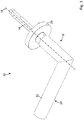
- a trigger is shown, which is designated as a whole by the reference numeral 10.
- the handle 10 is used to operate a locking device (not shown) of a door, a window or the like (not shown).
- the locking device can be, for example, a mortise lock for mounting in a door leaf.
- the pusher 10 has a handle 12 and a shaft 14, which can be pivoted about a common pivot axis 16.
- the pivot axis 16 is preferably aligned orthogonally to a door leaf of a door.
- the handle 12 is preferably designed as a door handle and has a first leg 18 oriented coaxially to the pivot axis 16 and a second leg 20 arranged at right angles to the first leg 18 (cf. Fig. 1 ).
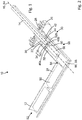
- the handle 12 is preferably designed as a hollow body with an opening 22 on the door side and delimits a central installation space 24 (cf. Fig. 2 ).
- the handle 12 is between a rest position shown in the drawing and an actuating position, in which the handle 12, preferably between 20 ° and 50 °, is pivoted about the pivot axis 16, pivotable.
- the shaft 14 is designed as a square and is used for coupling with the locking device. E.g. the shaft 14 can engage in a known manner in a follower of a mortise lock, so that pivoting the shaft 14 about the pivot axis 16 leads to an actuation of the locking device.
- the handle 10 can be fastened and stored in a manner known per se and therefore not explained in more detail via a rosette 26 on a door leaf (not shown).
- a restoring device in the form of a restoring spring 28 is preferably arranged in the rosette 26, which is used to act on the handle about the pivot axis 16 in the direction of the rest position (cf. Fig. 2 ).
- the handle 10 also has a coupling device 30, by means of which the handle 12 and the shaft 14 can optionally be coupled to one another in a rotationally fixed manner or can be uncoupled from one another (cf. Figures 3a to 4b ).
- the coupling device 30 has a first transmission element 32 that is non-rotatably connected to the handle 12 and a second transmission element 34 that is non-rotatably connected to the shaft 14.
- the first transmission element 32 and the second transmission element 34 are arranged coaxially to the pivot axis 16.
- the first transmission element 32 is designed as a hollow shaft and delimits a central receiving space 36.
- the first transmission element 32 is arranged in sections in the door-side opening 22 of the handle 12 and there connected to the handle 12 in a rotationally fixed manner. E.g. it is possible for the first transmission element 32 to be inserted into the installation space 24 of the handle 12 in a clamping manner. It is also possible for the first transmission element 32 to be connected to the handle 12 in a rotationally fixed manner via a screw connection (not shown).
- the second transmission element 34 has a first shaft-side connecting section 38, designed as a hollow shaft, and a second coupling section 40, which is preferably designed in one piece with the connecting section 38 but is at least non-rotatably connected.
- the connecting section 38 delimits a central receiving space 42 in which a shaft end 44 of the shaft 14 is received in a rotationally fixed manner (cf. Figures 3a and 3b ). It is possible, for example, for the receiving space 42 to have a cross section that is complementary to the cross section of the shaft 14, so that the connecting section 38 and the shaft end 44 form a positive connection effective in the direction about the pivot axis 16.
- the second transmission element 34 has a smaller outer diameter than the first transmission element 32 and is mounted pivotably about the pivot axis 16 in the receiving space 36 of the first transmission element 32 (cf. Figures 3a and 3b ).
- the first The transmission element 32 and the second transmission element 34 can therefore be pivoted relative to one another about the pivot axis 16.
- the first transmission element 32 and the second transmission element 34 can be connected to one another in a rotationally fixed manner by means of two coupling elements 46a, 46b.
- the second transmission element 34 has two recesses 48a, 48b in the area of the coupling section 40 for receiving a coupling element 46a, 46b each.
- the recesses 48a, 48b are designed in the form of radial bores, the bores being offset from one another at an angle of 180 ° around the pivot axis 16 - that is, they are arranged concentrically to a common displacement axis 50 oriented orthogonally to the pivot axis 16.
- the first transmission element 32 has recesses 52a, 52b complementary to the recesses 48a, 48b of the second transmission element 34, the recesses 52a, 52b of the first transmission element 32 and the recesses 48a, 48b of the second transmission element 34 being coaxial with one another in the rest position of the handle 12 and are thus aligned coaxially to the displacement axis 50 (cf. Figures 3a and 3b ).
- the coupling elements 46a, 46b are preferably designed as cylindrical bolts with a head 54a, 54b and a body 56a, 56b (cf. Figures 4a and 4b ).
- the respective head 54a, 54b has a larger cross section than the respective body 56a, 56b.
- the coupling elements 46a, 46b are in the recesses 48a, 48b, 52a, 52b along the displacement axis 50 between one in the Figures 3a and 4a shown decoupling and one in the Figures 3b and 4b shown coupling position slidably mounted.
- the coupling elements 46a, 46b are displaced radially outwardly along the displacement axis 50, starting from the uncoupling position, so that they engage both in sections in the respective recesses 48a, 48b of the second transmission element 34 and in sections in the respective recesses 52a, 52b of the first transmission element 32 .
- the coupling elements 46a, 46b consequently form with the two transmission elements 32, 34 in each case a positive connection effective in the direction about the pivot axis 16, so that the first transmission element 32 and the second transmission element 34 are rotatably coupled to one another.
- a pivoting of the handle 12 about the pivot axis 16 thus leads to an actuation of the locking device so that the door or the window can be opened.
- a drive device 58 is provided which is set up to move the coupling elements 46a, 46b between their respective decoupling position and their coupling position (cf. Figures 3a and 3b ).
- the drive device 58 has an eccentric element 60 which cooperates with the coupling elements 46a, 46b.
- the eccentric element 60 is arranged in a central receptacle 62 of the coupling section 40 of the second transmission element 34 and is mounted pivotably about an eccentric axis 64.
- the eccentric axis 64 preferably corresponds to the pivot axis 16.
- the drive device 58 also has a motor 66 for driving the eccentric element 60 about the eccentric axis 64.
- the motor 66 is arranged in the installation space 24 delimited by the first leg 18 of the handle 12, the motor 66 engaging in sections in the receiving space 36 formed by the first transmission element 32.
- the eccentric element 60 is designed as a double eccentric and has a substantially rectangular cross-section with two short sides 68a, 68b and two long sides 70a, 70b in the viewing direction along the eccentric axis 64 (cf. Figures 4a and 4b ).
- the corners are preferred rounded, with two diagonally opposite corners having a comparatively small radius of curvature and the two further diagonally opposite corners having a larger radius of curvature.
- the coupling elements 46a, 46b each bear with an end face 72a, 72b of the head 54a, 54b on the long sides 70a, 70b of the eccentric element 60.
- the coupling elements 46a, 46b are arranged in their radially innermost position and, as described above, are arranged completely in the respective recess 48a, 48b of the second transmission element 34.
- the coupling elements 46a, 46b are connected by means of a force application device 76 along a respective application direction (cf. arrows labeled 74a, 74b in FIG Figure 4a ) force-applied.
- the respective impingement direction is preferably aligned collinear with the displacement axis 50 of the coupling elements 46a, 46b and points radially inward in the direction of the eccentric element 60.
- the force application device 76 comprises two springs 78a, 78b, a spring 78a, 78b being assigned to each coupling element 46a, 46b.
- the respective spring 78a, 78b is supported with a first end on the head 48a, 48b of the respective coupling element 46a, 46b and with a second end on a contact surface 80a, 80b of the respective recess 48a, 48b of the second transmission element 34.
- the coupling elements 46a, 46b are pressed with their end faces 72a, 72b against the eccentric element 60 and thus always kept in contact with the eccentric element 60.
- the eccentric element 60 is based on the in Figure 4a position shown pivoted by 90 ° about the eccentric axis 64 (in the Figures 4a and 4b clockwise), the end faces 72a, 72b of the coupling elements 46a, 46b slide on the outer contour of the eccentric element 60.
- the coupling elements 46a, 46b are radially outward along the displacement axis 50 (in the direction of the in Figure 4a with arrows marked 82a, 82b) in their coupling position (cf. Figure 4b ) postponed.
- the coupling elements 46a, 46b then rest with their respective end faces 72a, 72b on the short sides 68a, 68b of the eccentric element 60.
- the coupling elements 46a, 46b - as described above - engage both in the respective recess 48a, 48b of the second transmission element 34 and in the respective recess 52a, 52b of the first transmission element 32.
- the springs 78a, 78b of the force application device 76 are tensioned. If the eccentric element 60 is returned to its in Figure 4a pivoted position shown, the springs 78a, 78b ensure that the coupling elements 46a, 46b in their in Figure 4a shown decoupling position are transferred - that is, moved radially inward along the displacement axis 50.
- the handle 10 also has a control device 84 for controlling the drive device 58 (cf. Figure 2 ).
- the control device 84 comprises access electronics 86 arranged in the installation space 24 of the handle 12 for the identification of an authorized person.
- the access electronics 86 include a reading device 88 for wirelessly reading out electronic identification carriers (not shown).
- the access electronics 86 If an identification carrier carrying an access authorization is brought up to the handle 12 so that the identification carrier is within reading range of the reading device 88, the access electronics 86 generate a signal which controls the motor 66 of the drive device 58 to the effect that the eccentric element 60 by an angle of 90 ° to pivot the eccentric axis 64 and, as a result, to move the coupling elements 46a, 46b in the direction of their coupling position.
- the lever handle 10 also has an energy storage device in the form of batteries 90, which are arranged in the installation space 24 of the handle 12, preferably in the second leg 20 (cf. Figure 2 ). It is possible for the second leg 20 of the handle 12 to have an opening 92, preferably closable, at the end, which is used to be able to exchange the batteries 90 if necessary.
Abstract
Die Erfindung betrifft einen Drücker (10) zur Betätigung einer Verriegelungseinrichtung einer Tür, eines Fensters oder dgl. mit einer Handhabe (12), mit einer Welle (14) zur Verbindung mit der Verriegelungseinrichtung und mit einer Kupplungseinrichtung (30) zur Kupplung von Handhabe und Welle, wobei die Handhabe und die Welle um eine gemeinsame Schwenkachse (16) verschwenkbar sind, wobei die Kupplungseinrichtung mindestens ein Kupplungselement (46a, 46b) aufweist, welches zwischen einer Kuppelstellung, bei der die Handhabe und die Welle miteinander gekuppelt sind, und einer Entkuppelstellung, bei der die Handhabe und die Welle voneinander entkuppelt sind, bewegbar ist, wobei die Kupplungseinrichtung zumindest abschnittsweise innerhalb eines durch die Handhabe begrenzten Bauraums (24) angeordnet ist und im gekuppelten Zustand bei einer Betätigung der Handhabe um die Schwenkachse mitschwenkt, und wobei das mindestens eine Kupplungselement entlang eines zu der Schwenkachse in radialer Richtung orientierten Verschiebewegs verschiebbar ist.The invention relates to a handle (10) for actuating a locking device of a door, a window or the like. With a handle (12), with a shaft (14) for connection to the locking device and with a coupling device (30) for coupling the handle and Shaft, the handle and the shaft being pivotable about a common pivot axis (16), the coupling device having at least one coupling element (46a, 46b) which is between a coupling position, in which the handle and the shaft are coupled to one another, and a decoupling position , in which the handle and the shaft are decoupled from one another, is movable, the coupling device being arranged at least in sections within an installation space (24) limited by the handle and, in the coupled state, pivoting about the pivot axis when the handle is actuated, and at least a coupling element along a to the pivot axis in radial Ric Attention-oriented displacement path is displaceable.
Description
Die Erfindung betrifft einen Drücker zur Betätigung einer Verriegelungseinrichtung einer Tür, eines Fensters oder dgl. mit einer Handhabe, mit einer Welle zur Verbindung mit der Verriegelungseinrichtung und mit einer Kupplungseinrichtung zur Kupplung von Handhabe und Welle, wobei die Handhabe und die Welle um eine gemeinsame Schwenkachse verschwenkbar sind, wobei die Kupplungseinrichtung mindestens ein Kupplungselement aufweist, welches zwischen einer Kuppelstellung, bei der die Handhabe und die Welle miteinander gekuppelt sind, und einer Entkuppelstellung, bei der die Handhabe und die Welle voneinander entkuppelt sind, bewegbar ist, und wobei die Kupplungseinrichtung zumindest abschnittsweise innerhalb eines durch die Handhabe begrenzten Bauraums angeordnet ist und im gekuppelten Zustand bei einer Betätigung der Handhabe um die Schwenkachse mitschwenkt.The invention relates to a handle for actuating a locking device of a door, a window or the like. With a handle, with a shaft for connection to the locking device and with a coupling device for coupling the handle and shaft, the handle and the shaft about a common pivot axis are pivotable, wherein the coupling device has at least one coupling element which between a coupling position in which the handle and the shaft are coupled to one another, and a decoupling position, in which the handle and the shaft are decoupled from each other, is movable, and wherein the coupling device is arranged at least in sections within an installation space limited by the handle and, in the coupled state, pivots about the pivot axis when the handle is actuated.
Vorstehend genannte Drücker sind aus dem Stand der Technik beispielsweise aus der
Der vorliegenden Erfindung liegt die Aufgabe zugrunde, einen Drücker bereitzustellen, der eine zuverlässige Funktion bei besonders kompakter Bauweise gewährleistet.The present invention is based on the object of providing a lever handle which ensures reliable operation with a particularly compact design.
Diese Aufgabe wird bei einem Drücker der eingangs genannten Art erfindungsgemäß dadurch gelöst, dass das mindestens eine Kupplungselement entlang eines zu der Schwenkachse in radialer Richtung orientierten Verschiebewegs verschiebbar ist.This object is achieved according to the invention in a lever handle of the type mentioned at the outset in that the at least one coupling element can be displaced along a displacement path oriented in the radial direction relative to the pivot axis.
Der erfindungsgemäße Drücker zeichnet sich durch einen besonders kompakten Aufbau der Kupplungseinrichtung aus. Dadurch, dass der Verschiebeweg des mindestens einen Kupplungselements in radialer Richtung orientiert ist, kann insbesondere der in axialer Richtung erforderliche Bauraum minimiert werden. Ein erfindungsgemäßer Drücker kann daher in axialer Richtung vergleichsweise schmal ausgebildet sein. Dies hat den Vorteil, dass der Drücker in einem montierten Zustand nur in geringem Maße von einem Türblatt absteht, wodurch das Risiko, dass Personen oder Gegenstände an dem Drücker hängenbleiben, verringert werden kann.The lever handle according to the invention is characterized by a particularly compact construction of the coupling device. The fact that the displacement path of the at least one coupling element is oriented in the radial direction can in particular, the space required in the axial direction can be minimized. A handle according to the invention can therefore be made comparatively narrow in the axial direction. This has the advantage that the handle only protrudes to a small extent from a door leaf in an assembled state, as a result of which the risk of people or objects getting caught on the handle can be reduced.
In der Kuppelstellung des mindestens einen Kupplungselements sind die Handhabe und die Welle um die Schwenkachse drehfest miteinander verbunden. Ein Verschwenken der Handhabe um die Schwenkachse führt somit zu einem Verschwenken der Welle und infolgedessen zu einer Betätigung einer mit der Welle gekoppelten Verriegelungseinrichtung. Im gekuppelten Zustand kann also eine Tür, ein Fenster oder dgl. durch eine Betätigung der Handhabe geöffnet werden.In the coupled position of the at least one coupling element, the handle and the shaft are connected to one another in a rotationally fixed manner about the pivot axis. A pivoting of the handle about the pivot axis thus leads to a pivoting of the shaft and consequently to an actuation of a locking device coupled to the shaft. In the coupled state, a door, a window or the like can be opened by actuating the handle.
In der Entkuppelstellung des mindestens einen Kupplungselements ist der Kraftfluss zwischen Handhabe und Verriegelungseinrichtung unterbrochen. Ein Verschwenken der Handhabe führt folglich nicht zu einem Verschwenken der Welle und somit zu keiner Betätigung der Verriegelungseinrichtung. Im entkuppelten Zustand kann die Tür, das Fenster oder dgl. also durch eine Betätigung der Handhabe nicht geöffnet werden.In the uncoupling position of the at least one coupling element, the flow of force between the handle and the locking device is interrupted. A pivoting of the handle consequently does not lead to a pivoting of the shaft and thus to no actuation of the locking device. In the uncoupled state, the door, window or the like cannot be opened by actuating the handle.
Insbesondere ist bei einem erfindungsgemäßen Drücker eine Schwenkbewegung der Handhabe um die Schwenkachse unabhängig von einem Kupplungszustand der Kupplungseinrichtung stets möglich. Auf diese Weise kann - im Gegensatz zu Drückern, die zum Sperren der Verriegelungseinrichtung eine Schwenkbewegung der Handhabe blockieren - das Risiko verringert werden, dass ein Benutzer bei erfolglosem Öffnungsversuch die Handhabe gewaltsam zu verschwenken versucht und dabei den Drücker beschädigt.In particular, with a handle according to the invention, a pivoting movement of the handle about the pivot axis is always possible regardless of a coupling state of the coupling device. In this way - in contrast to pushers, which block a pivoting movement of the handle to lock the locking device - the risk is reduced that a user tries to pivot the handle forcibly if the opening attempt is unsuccessful and thereby damages the lever handle.
Es ist möglich, dass lediglich ein Kupplungselement vorgesehen ist. Bevorzugt ist es jedoch, wenn mehrere Kupplungselemente vorgesehen sind, welche vorzugsweise entlang eines Umfangs um die Schwenkachse verteilt angeordnet sind. Hierdurch wird eine besonders zuverlässige und verschleißarme Kraftübertragung zwischen Handhabe und Welle ermöglicht, da die Kraftübertragung über mehrere Kupplungselemente verteilt wird, sodass eine jeweils an den einzelnen Kupplungselementen anliegende Scherkraft niedriger ist als bei Verwendung nur eines
Kupplungselements.It is possible that only one coupling element is provided. It is preferred, however, if several coupling elements are provided, which are preferably arranged distributed along a circumference around the pivot axis. This enables a particularly reliable and low-wear power transmission between the handle and the shaft, since the power transmission is distributed over several coupling elements, so that the shear force applied to the individual coupling elements is lower than when only one is used
Coupling element.
Besonders bevorzugt ist es, wenn zwei Kupplungselemente vorgesehen sind, die in einem Winkel von 180° um die Schwenkachse zueinander versetzt angeordnet sind. Die Verschiebewege der Kupplungselemente liegen dann auf einer gemeinsamen Verschiebeachse. Dies ermöglicht es, auf besonders einfache Weise beide Kupplungselemente gemeinsam zwischen der Entkuppelstellung und der Kuppelstellung zu verschieben, was einen kompakten Aufbau der Kupplungseinrichtung begünstigt.It is particularly preferred if two coupling elements are provided which are offset from one another at an angle of 180 ° around the pivot axis. The displacement paths of the coupling elements then lie on a common displacement axis. This makes it possible to move both coupling elements together between the uncoupling position and the coupling position in a particularly simple manner, which favors a compact design of the coupling device.
Bei der Verriegelungseinrichtung handelt es sich vorzugsweise um ein Einsteckschloss zur Montage in einem Türblatt. Die Welle ist vorzugsweise als Mehrkant, insbesondere als Vierkant, ausgebildet, und wirkt mit der Verriegelungseinrichtung zusammen. Vorzugsweise greift die Welle in die "Nuss" eines Einsteckschlosses ein.The locking device is preferably a mortise lock for mounting in a door leaf. The shaft is preferably designed as a polygon, in particular as a square, and acts with the Locking device together. The shaft preferably engages in the "socket" of a mortise lock.
Die Handhabe ist vorzugsweise als "Türklinke" bzw. "Türgriff" ausgebildet mit einem ersten, koaxial zur Schwenkachse angeordneten Schenkel und einem zweiten, zu dem ersten Schenkel winklig, vorzugsweise rechtwinklig, angeordneten Schenkel. Die Handhabe ist vorzugsweise als Hohlkörper ausgebildet und begrenzt einen zentralen Bauraum.The handle is preferably designed as a “door handle” or “door handle” with a first leg arranged coaxially to the pivot axis and a second leg arranged at an angle, preferably at right angles, to the first leg. The handle is preferably designed as a hollow body and delimits a central installation space.
Bei einer bevorzugten Ausführungsform weist die Kupplungseinrichtung eine Antriebseinrichtung mit mindestens einem um eine Exzenterachse verschwenkbaren Exzenterelement auf, wobei das mindestens eine Exzenterelement an dem mindestens einen Kupplungselement angreift, um dieses längs des Verschiebewegs in zumindest einer ersten Richtung anzutreiben. Eine solche Ausgestaltung ermöglicht es, mit vergleichsweise einfachen konstruktiven Mitteln die Kupplungseinrichtung zu schalten. Durch ein Verschwenken des mindestens einen Exzenterelements um die Exzenterachse kann das mindestens eine Kupplungselement radial zur Schwenkachse verschoben werden und somit ein Kupplungszustand der Kupplungseinrichtung verändert werden. Eine vorstehend beschriebene Antriebseinrichtung zeichnet sich ferner durch vergleichsweise wenig bewegte Teile aus (kein zusätzliches Getriebe erforderlich), was eine besonders robuste und zuverlässige Funktion der Kupplungseinrichtung begünstigt. Es ist möglich, dass das mindestens eine Kupplungselement in einer Ausgangsstellung mit einer Anlagefläche an dem mindestens einen Exzenterelement anliegt. In diesem Fall kann das mindestens eine Exzenterelement - im Zuge einer Schwenkbewegung dessen um die Exzenterachse - das mindestens eine Kupplungselement längs des Verschiebewegs aus der Ausgangsstellung in einer ersten Richtung antreiben. Bei der Ausgangsstellung kann es sich um die Kuppelstellung handeln. Besonders bevorzugt ist es jedoch, wenn es sich bei der Ausgangsstellung um die Entkuppelstellung handelt. In diesem Fall kann die erste Richtung der Verschieberichtung des Kupplungselements oder der Kupplungselemente von der Entkuppelstellung in die Kuppelstellung entsprechen.In a preferred embodiment, the coupling device has a drive device with at least one eccentric element pivotable about an eccentric axis, the at least one eccentric element engaging the at least one coupling element in order to drive it along the displacement path in at least one first direction. Such a configuration makes it possible to switch the clutch device with comparatively simple structural means. By pivoting the at least one eccentric element about the eccentric axis, the at least one coupling element can be displaced radially to the pivot axis and thus a coupling state of the coupling device can be changed. A drive device described above is also characterized by comparatively little moving parts (no additional gear required), which promotes a particularly robust and reliable function of the coupling device. It is possible for the at least one coupling element to bear against the at least one eccentric element in an initial position with a contact surface. In this case, the at least one eccentric element can drive the at least one coupling element along the displacement path from the initial position in a first direction in the course of a pivoting movement thereof about the eccentric axis. The starting position can be the coupling position. It is particularly preferred, however, if the starting position is the uncoupling position. In this case, the first direction can correspond to the direction of displacement of the coupling element or the coupling elements from the decoupling position into the coupling position.
Es ist auch möglich, dass das mindestens eine Kupplungselement mit einem Antriebsabschnitt des mindestens einen Exzenterelements gelenkig verbunden ist. In diesem Fall kann das mindestens eine Exzenterelement das mindestens eine Kupplungselement in zwei zueinander entgegengesetzten Richtungen längs des Verschiebewegs antreiben. Dabei kann eine erste Richtung der Verschieberichtung von der Entkuppelstellung in die Kuppelstellung und die der ersten Richtung entgegengesetzte zweite Richtung der Verschieberichtung von der Kuppelstellung in die Entkuppelstellung entsprechen. Auf diese Weise kann durch Verschwenken des mindestens einen Exzenterelements um die Schwenkachse die Kupplungseinrichtung zwischen gekuppeltem und entkuppeltem Zustand wiederholbar hin und her geschaltet werden. Vorzugsweise ist das mindestens eine Exzenterelement als Doppelexzenter ausgebildet. Dies ermöglicht es, zwei Kupplungselemente gleichzeitig entlang deren jeweiliger Verschiebewege anzutreiben.It is also possible for the at least one coupling element to be connected in an articulated manner to a drive section of the at least one eccentric element. In this case, the at least one eccentric element can drive the at least one coupling element in two mutually opposite directions along the displacement path. A first direction can correspond to the direction of displacement from the decoupling position into the coupling position and the second direction, which is opposite to the first direction, can correspond to the direction of displacement from the coupling position into the decoupling position. In this way, by pivoting the at least one eccentric element about the pivot axis, the coupling device can be repeatedly switched back and forth between the coupled and uncoupled states. The at least one eccentric element is preferably designed as a double eccentric. This makes it possible to drive two coupling elements simultaneously along their respective displacement paths.
Bevorzugt ist es ferner, wenn die Antriebseinrichtung einen elektrisch betriebenen Motor umfasst, welcher den mindestens einen Exzenter in Richtung um die Exzenterachse antreibt.It is also preferred if the drive device comprises an electrically operated motor which drives the at least one eccentric in the direction about the eccentric axis.
Im Rahmen einer bevorzugten Ausgestaltung kann die Antriebseinrichtung innerhalb des durch die Handhabe begrenzten Bauraums angeordnet sein. Auf diese Weise ist die Antriebseinrichtung vor Umwelteinflüssen und/oder Verschmutzungen geschützt, was vorteilhaft für einen Einsatz des Drückers im Außenbereich ist. Darüber hinaus kann der Drücker auf diese Weise als in sich funktionsfähige Baueinheit ausgebildet sein, sodass beim Umrüsten eines bestehenden Türsystems mit einem erfindungsgemäßen Drücker keine zusätzlichen Umbauten an einem Türblatt oder Türrahmen (z.B. zur räumlichen Integration einer Antriebseinrichtung) erforderlich sind.In the context of a preferred embodiment, the drive device can be arranged within the installation space limited by the handle. In this way, the drive device is protected from environmental influences and / or soiling, which is advantageous for using the lever handle outdoors. In addition, the handle can be designed as a self-functional unit, so that when converting an existing door system with a handle according to the invention, no additional modifications to a door leaf or door frame (e.g. for the spatial integration of a drive device) are required.
Ferner ist es bevorzugt, wenn die Exzenterachse parallel, vorzugsweise kollinear, zu der Schwenkachse ausgerichtet ist. Dies begünstigt eine kompakte Bauweise des Drückers, da ein Antrieb des mindestens einen Exzenterelements auf besonders platzsparende Art und Weise in dem koaxial zur Schwenkachse angeordneten Teil der Handhabe angeordnet sein kann, und zwar ohne dass ein zusätzliches Getriebe zum Antrieb des mindestens einen Exzenterelements erforderlich ist.It is also preferred if the eccentric axis is aligned parallel, preferably collinear, to the pivot axis. This favors a compact design of the handle, since a drive of the at least one eccentric element can be arranged in a particularly space-saving manner in the part of the handle arranged coaxially to the pivot axis, without the need for an additional gear Drive of the at least one eccentric element is required.
Bei einer weiteren bevorzugten Ausführungsform weist der Drücker eine Kraftbeaufschlagungseinrichtung auf, welche längs einer Beaufschlagungsrichtung wirksam ist und das mindestens eine Kupplungselement in Richtung der Kuppelstellung oder der Entkuppelstellung beaufschlagt. Dies ermöglicht es, eine Vorzugsstellung des mindestens einen Kupplungselements vorzugeben. Bei der Vorzugsstellung kann es sich bspw. um die Kuppelstellung oder die Entkuppelstellung handeln.In a further preferred embodiment, the handle has a force application device which is effective along a direction of application and acts on the at least one coupling element in the direction of the coupling position or the uncoupling position. This makes it possible to specify a preferred position of the at least one coupling element. The preferred position can be, for example, the coupling position or the uncoupling position.
Besonders bevorzugt ist es, wenn die Beaufschlagungsrichtung derart orientiert ist, dass das mindestens eine Kupplungselement durch die Kraftbeaufschlagungseinrichtung gegen das mindestens eine Exzenterelement gedrückt wird. Hierdurch kann sichergestellt werden, dass das mindestens eine Kupplungselement stets in Kontakt mit dem mindestens einen Exzenterelement steht und eine Antriebsbewegung des mindestens einen Exzenterelements sicher auf das mindestens eine Kupplungselement übertragen werden kann.It is particularly preferred if the direction of application is oriented such that the at least one coupling element is pressed against the at least one eccentric element by the force application device. This can ensure that the at least one coupling element is always in contact with the at least one eccentric element and a drive movement of the at least one eccentric element can be reliably transmitted to the at least one coupling element.
Besonders bevorzugt ist es ferner, wenn die Beaufschlagungsrichtung längs des Verschiebewegs und entgegengesetzt zu einer von dem mindestens einen Exzenterelement bewirkten Verschieberichtung (Antriebsrichtung) des jeweiligen Kupplungselements orientiert ist. Dies ermöglicht es, das jeweilige Kupplungselement - nach einer Verschiebung dessen aus seiner Ausgangsstellung durch das mindestens eine Exzenterelement - wieder in seine Ausgangsstellung zurückzuführen.It is also particularly preferred if the direction of application is oriented along the displacement path and opposite to a displacement direction (drive direction) of the respective coupling element effected by the at least one eccentric element. This enables the respective coupling element - after it has been shifted off its starting position by the at least one eccentric element - returned to its starting position.
Bevorzugt ist es ferner, wenn die Kraftbeaufschlagungseinrichtung in Form einer Federeinrichtung ausgebildet ist. Besonders bevorzugt ist es, wenn für jedes Kupplungselement eine separate Feder vorgesehen ist, welche parallel zu der Verschiebeachse des jeweiligen Kupplungselements ausgerichtet ist. Hierdurch wird auf konstruktiv einfache und kostengünstige Weise eine zuverlässige Beaufschlagung des mindestens einen Kupplungselements begünstigt.It is also preferred if the force application device is designed in the form of a spring device. It is particularly preferred if a separate spring is provided for each coupling element, which spring is aligned parallel to the displacement axis of the respective coupling element. In this way, a reliable application of the at least one coupling element is promoted in a structurally simple and inexpensive manner.
Bei einer weiteren bevorzugten Ausführungsform weist die Kupplungseinrichtung ein erstes, mit der Handhabe drehfest verbundenes Übertragungselement und ein zweites, mit der Welle drehfest verbundenes Übertragungselement auf, wobei das erste und das zweite Übertragungselement jeweils eine, einem jeweiligen Kupplungselement zugeordnete Ausnehmung zur zumindest abschnittsweisen Aufnahme des jeweiligen Kupplungselements aufweisen. Besonders bevorzugt ist es, wenn die Ausnehmungen des ersten und des zweiten Übertragungselements als radiale Bohrungen ausgebildet sind, welche in einer Ruhestellung der Handhabe koaxial zueinander orientiert sind.In a further preferred embodiment, the coupling device has a first transmission element connected in a rotationally fixed manner to the handle and a second transmission element connected in a rotationally fixed manner to the shaft, the first and the second transmission element each having a recess assigned to a respective coupling element for receiving the respective one at least in sections Have coupling element. It is particularly preferred if the recesses of the first and the second transmission element are designed as radial bores, which are oriented coaxially to one another in a rest position of the handle.
In der Kuppelstellung kann das jeweilige Kupplungselement zumindest abschnittsweise sowohl in die ihm zugeordnete Ausnehmung des ersten Übertragungselements als auch in die ihm zugeordnete Ausnehmung des zweiten Übertragungselements eingreifen. Besonders bevorzugt ist es, wenn das mindestens eine Kupplungselement in der Kuppelstellung sowohl mit dem ersten Übertragungselement als auch mit dem zweiten Übertragungselement eine in Richtung um die Schwenkachse wirkende formschlüssige Verbindung bildet. Auf diese Weise wird eine besonders sichere Kraftübertragung zwischen Handhabe und Welle und somit ein besonders zuverlässige Betätigung der Verriegelungseinrichtung ermöglicht.In the coupling position, the respective coupling element can, at least in sections, both in the recess of the first transmission element assigned to it and in the recess of the second transmission element assigned to it intervention. It is particularly preferred if the at least one coupling element in the coupling position forms a positive connection acting in the direction about the pivot axis both with the first transmission element and with the second transmission element. In this way, a particularly secure transmission of force between the handle and the shaft and thus a particularly reliable actuation of the locking device is made possible.
Es ist möglich, dass das erste Übertragungselement einstückig mit der Handhabe ausgebildet ist und/oder dass das zweite Übertragungselement einstückig mit der Welle ausgebildet ist. Besonders bevorzugt ist es jedoch, wenn die Übertragungselemente von der Handhabe bzw. der Welle separat bereitgestellt sind. Auf diese Weise kann die Kupplungseinrichtung als eine von der Handhabe und der Welle unabhängige Baueinheit ausgebildet sein. Dies ermöglicht es, "herkömmliche" Drücker, umfassend eine Handhabe und eine Welle, auf besonders einfache Weise mit einer erfindungsgemäßen Kupplungseinrichtung nachzurüsten.It is possible that the first transmission element is formed in one piece with the handle and / or that the second transmission element is formed in one piece with the shaft. However, it is particularly preferred if the transmission elements are provided separately from the handle or the shaft. In this way, the coupling device can be designed as a structural unit that is independent of the handle and the shaft. This makes it possible to retrofit "conventional" handles, comprising a handle and a shaft, in a particularly simple manner with a coupling device according to the invention.
Ferner ist es bevorzugt, wenn das erste Übertragungselement und/oder das zweite Übertragungselement als Hohlwelle ausgebildet sind/ist und wenn entweder das erste Übertragungselement zumindest abschnittsweise in einem durch das zweite Übertragungselement gebildeten Aufnahmeraum angeordnet ist oder das zweite Übertragungselement zumindest abschnittsweise in einem durch das erste Übertragungselement gebildeten Aufnahmeraum angeordnet ist. Auf diese Weise wird ein besonders kompakter Aufbau der Kupplungseinrichtung erzielt, sodass insbesondere in axialer Richtung nur vergleichsweise wenig Bauraum beansprucht wird. Bevorzugt ist es ferner, wenn die Antriebseinrichtung zumindest abschnittsweise in dem durch das außenliegende Übertragungselement gebildeten Aufnahmeraum angeordnet ist.Furthermore, it is preferred if the first transmission element and / or the second transmission element are / is designed as a hollow shaft and if either the first transmission element is arranged at least in sections in a receiving space formed by the second transmission element or the second transmission element at least in sections in a space formed by the first Transmission element formed receiving space is arranged. In this way, a particularly compact design of the coupling device is achieved, so that In particular, only comparatively little space is required in the axial direction. It is also preferred if the drive device is arranged at least in sections in the receiving space formed by the external transmission element.
Bei einer weiteren bevorzugten Ausführungsform umfasst der Drücker eine Steuereinrichtung zur Ansteuerung der Antriebseinrichtung der Kupplungseinrichtung. Dies ermöglicht es, den Kupplungszustand der Kupplungseinrichtung zu steuern und somit das Öffnen einer Tür oder eines Fensters freizugeben oder zu sperren.In a further preferred embodiment, the lever includes a control device for controlling the drive device of the coupling device. This makes it possible to control the coupling state of the coupling device and thus to enable or disable the opening of a door or a window.
Besonders bevorzugt ist es, wenn die Steuereinrichtung eine Zutrittselektronik zur Identifikation einer autorisierten Person aufweist, wobei die Zutrittselektronik dazu eingerichtet ist, bei vorliegender Zutrittsberechtigung ein Signal zu erzeugen, welches die Antriebseinrichtung veranlasst, das mindestens eine Kupplungselement aus der Entkuppelstellung in die Kuppelstellung zu überführen. Auf diese Weise kann sichergestellt werden, dass nur autorisierte Personen mit entsprechender Zutrittsberechtigung eine Tür öffnen können.It is particularly preferred if the control device has access electronics for identifying an authorized person, the access electronics being set up to generate a signal, if the access authorization is present, which causes the drive device to move the at least one coupling element from the uncoupling position to the coupling position. In this way it can be ensured that only authorized persons with the appropriate access authorization can open a door.
Besonders bevorzugt ist es ferner, wenn die Zutrittselektronik in der Handhabe angeordnet ist. Dies ermöglicht es, die Zutrittselektronik und die Kupplungseinrichtung, welche ebenfalls zumindest abschnittsweise in der Handhabe angeordnet ist, auf einfache Weise und mit geringem Verkabelungsaufwand miteinander zu verbinden. Ferner ermöglicht eine solche Ausgestaltung eine einfach zu bewerkstelligende und kostengünstige Nachrüstung eines bestehenden Türsystems mit einer Zutrittselektronik, da zur Nachrüstung lediglich die Handhabe ausgetauscht werden muss und nicht - wie es bspw. bei neben einer Tür angeordneten Kartenlesern der Fall ist - Umbauten an Türblatt und/oder Türrahmen vorgenommen werden müssen.It is also particularly preferred if the access electronics are arranged in the handle. This makes it possible to connect the access electronics and the coupling device, which is also arranged at least in sections in the handle, to one another in a simple manner and with little cabling effort. Furthermore, such a Design an easy-to-do and inexpensive retrofitting of an existing door system with access electronics, since for retrofitting only the handle has to be replaced and not - as is the case, for example, with card readers arranged next to a door - conversions are made to the door leaf and / or door frame have to.
Die Zutrittselektronik kann bspw. einen Fingerabdrucksensor oder eine numerische Pin-Code Abfrageeinheit umfassen. Besonders bevorzugt ist es jedoch, wenn die Zutrittselektronik eine Leseeinrichtung zum drahtlosen Auslesen von elektronischen Identifikationsträgern umfasst. Um einen Zutritt freizugeben, muss der Identifikationsträger somit lediglich an die Handhabe gehalten oder zumindest in deren Nähe gebracht werden. Dies ermöglicht eine intuitive und komfortable Bedienung des Drückers. Zum drahtlosen Auslesen können verschiedene an sich bekannte Technologien zum Einsatz kommen, bspw. SE, BLE, RFID, NFC, Funk, etc.The access electronics can include, for example, a fingerprint sensor or a numerical pin code interrogation unit. However, it is particularly preferred if the access electronics include a reading device for wirelessly reading out electronic identification carriers. In order to release access, the identification carrier only has to be held up to the handle or at least brought close to it. This enables intuitive and convenient operation of the handle. Various technologies known per se can be used for wireless reading, e.g. SE, BLE, RFID, NFC, radio, etc.
Ferner ist es bevorzugt, wenn in der Handhabe mindestens eine Batterie zur Energieversorgung der Antriebseinrichtung und/oder der Steuereinrichtung angeordnet ist. Auf diese Weise kann eine von externen Energiequellen unabhängige Stromversorgung der Antriebseinrichtung und/oder der Steuereinrichtung gewährleistet werden. Der erfindungsgemäße Drücker kann folglich als funktionsfähige Baueinheit an einem Türblatt angeordnet werden, ohne dass es weiterer baulicher Maßnahmen zur Sicherung der Stromversorgung bedarf, was eine einfache Nachrüstung bestehender Türsysteme begünstigt.It is also preferred if at least one battery for supplying energy to the drive device and / or the control device is arranged in the handle. In this way, a power supply for the drive device and / or the control device that is independent of external energy sources can be ensured. The handle according to the invention can consequently be arranged as a functional structural unit on a door leaf without the need for further structural measures to secure the Power supply is required, which makes it easy to retrofit existing door systems.
Ferner ist es bevorzugt, wenn der Drücker eine Rückstelleinrichtung, vorzugsweise in Form einer Federeinrichtung, aufweist, welche dazu eingerichtet ist, die Handhabe um die Schwenkachse in Richtung einer Ruhestellung zu beaufschlagen. Hiermit kann eine zuverlässige Rückstellung der Handhabe in die Ruhestellung erreicht werden, und zwar unabhängig von der Verriegelungseinrichtung.Furthermore, it is preferred if the pusher has a resetting device, preferably in the form of a spring device, which is set up to act on the handle about the pivot axis in the direction of a rest position. A reliable return of the handle to the rest position can hereby be achieved, independently of the locking device.
Weitere Merkmale und Vorteile der Erfindung sind Gegenstand der nachfolgenden Beschreibung und der zeichnerischen Darstellung eines bevorzugten Ausführungsbeispiels.Further features and advantages of the invention are the subject matter of the following description and the drawing of a preferred exemplary embodiment.
In der Zeichnung zeigen
- Fig. 1
- eine perspektivische Ansicht eines Drückers;
- Fig. 2
- eine perspektivische Ansicht des Drückers gemäß
Fig. 1 in einem Horizontalschnitt; - Fig. 3a
- eine Draufsicht des Drückers gemäß
Fig. 2 mit Kupplungselementen in Entkuppelstellung; - Fig. 3b
- eine Draufsicht des Drückers gemäß
Fig. 2 mit Kupplungselementen in Kuppelstellung; - Fig. 4a
- eine Schnittansicht des Drückers gemäß
Fig. 3a längs einer inFig. 3a mit IVa - IVa bezeichneten Schnittebene in einer vergrößerten Darstellung; und - Fig. 4b
- eine Schnittansicht des Drückers gemäß
Fig. 3b längs einer inFig. 3b mit IVb - IVb bezeichneten Schnittebene in einer vergrößerten Darstellung.
- Fig. 1
- a perspective view of a pusher;
- Fig. 2
- a perspective view of the trigger according to
Fig. 1 in a horizontal section; - Fig. 3a
- a top view of the trigger according to
Fig. 2 with coupling elements in decoupling position; - Figure 3b
- a top view of the trigger according to
Fig. 2 with coupling elements in coupling position; - Figure 4a
- a sectional view of the trigger according to
Fig. 3a along one inFig. 3a labeled IVa - IVa Sectional plane in an enlarged illustration; and - Figure 4b
- a sectional view of the trigger according to
Figure 3b along one inFigure 3b with IVb-IVb designated sectional plane in an enlarged representation.
In
Der Drücker 10 weist eine Handhabe 12 und eine Welle 14 auf, welche um eine gemeinsame Schwenkachse 16 verschwenkbar sind. Im montierten Zustand des Drückers 10 ist die Schwenkachse 16 vorzugsweise orthogonal zu einem Türblatt einer Tür ausgerichtet.The
Die Handhabe 12 ist vorzugsweise als Türklinke ausgebildet und weist einen ersten, koaxial zu der Schwenkachse 16 orientierten Schenkel 18 und einen zweiten, zu dem ersten Schenkel 18 rechtwinklig angeordneten Schenkel 20 auf (vgl.
Die Handhabe 12 ist zwischen einer in der Zeichnung dargestellten Ruhestellung und einer Betätigungsstellung, in welcher die Handhabe 12, vorzugsweise zwischen 20° und 50°, um die Schwenkachse 16 verschwenkt ist, verschwenkbar.The
Die Welle 14 ist als Vierkant ausgebildet und dient zur Kopplung mit der Verriegelungseinrichtung. Bspw. kann die Welle 14 in an sich bekannter Weise in eine Drückernuss eines Einsteckschlosses eingreifen, sodass ein Verschwenken der Welle 14 um die Schwenkachse 16 zu einer Betätigung der Verriegelungseinrichtung führt.The
Der Drücker 10 kann in an sich bekannter Weise und daher nicht näher erläutert über eine Rosette 26 an einem Türblatt (nicht dargestellt) befestigt und gelagert werden. Vorzugsweise ist in der Rosette 26 eine Rückstelleinrichtung in Form einer Rückstellfeder 28 angeordnet, welche dazu dient, die Handhabe um die Schwenkachse 16 in Richtung der Ruhestellung zu beaufschlagen (vgl.
Der Drücker 10 weist ferner eine Kupplungseinrichtung 30 auf, mittels derer die Handhabe 12 und die Welle 14 wahlweise miteinander drehfest gekuppelt oder voneinander entkuppelt werden können (vgl.
Das erste Übertragungselement 32 ist als Hohlwelle ausgebildet und begrenzt einen zentralen Aufnahmeraum 36. Das erste Übertragungselement 32 ist abschnittsweise in der türseitigen Öffnung 22 der Handhabe 12 angeordnet und dort drehfest mit der Handhabe 12 verbunden. Bspw. ist es möglich, dass das erste Übertragungselement 32 klemmend in dem Bauraum 24 der Handhabe 12 eingesteckt ist. Es ist auch möglich, dass das erste Übertragungselement 32 mit der Handhabe 12 über eine nicht dargestellte Schraubverbindung drehfest miteinander verbunden ist.The
Das zweite Übertragungselement 34 weist einen ersten, als Hohlwelle ausgebildeten wellenseitigen Verbindungsabschnitt 38 und einen zweiten, mit dem Verbindungsabschnitt 38 vorzugsweise einstückig ausgebildeten, zumindest aber drehfest verbundenen Kupplungsabschnitt 40 auf.The
Der Verbindungsabschnitt 38 begrenzt einen zentralen Aufnahmeraum 42, in dem ein Wellenende 44 der Welle 14 drehfest aufgenommen ist (vgl.
Das zweite Übertragungselement 34 weist einen betragsmäßig kleineren Außendurchmesser als das erste Übertragungselement 32 auf und ist in dem Aufnahmeraum 36 des ersten Übertragungselements 32 um die Schwenkachse 16 schwenkbar gelagert (vgl.
Das erste Übertragungselement 32 und das zweite Übertragungselement 34 sind mittels zweier Kupplungselemente 46a, 46b miteinander drehfest verbindbar. Zu diesem Zweck weist das zweite Übertragungselement 34 im Bereich des Kupplungsabschnittes 40 zwei Ausnehmungen 48a, 48b zur Aufnahme jeweils eines Kupplungselements 46a, 46b auf. Die Ausnehmungen 48a, 48b sind in Form von radialen Bohrungen ausgebildet, wobei die Bohrungen in einem Winkel von 180° um die Schwenkachse 16 zueinander versetzt angeordnet sind - also konzentrisch zu einer gemeinsamen, orthogonal zu der Schwenkachse 16 orientierten Verschiebeachse 50 angeordnet sind.The
Das erste Übertragungselement 32 weist zu den Ausnehmungen 48a, 48b des zweiten Übertragungselements 34 komplementäre Ausnehmungen 52a, 52b auf, wobei die Ausnehmungen 52a, 52b des ersten Übertragungselements 32 und die Ausnehmungen 48a, 48b des zweiten Übertragungselements 34 in der Ruhestellung der Handhabe 12 koaxial zueinander und somit koaxial zu der Verschiebeachse 50 ausgerichtet sind (vgl.
Die Kupplungselemente 46a, 46b sind vorzugsweise als zylindrische Bolzen ausgebildet mit einem Kopf 54a, 54b und einem Körper 56a, 56b (vgl.
Die Kupplungselemente 46a, 46b sind in den Ausnehmungen 48a, 48b, 52a, 52b längs der Verschiebeachse 50 zwischen einer in den
In der Entkuppelstellung (vgl.
In der Kuppelstellung (vgl.
Zum Schalten der Kupplungseinrichtung 30 ist eine Antriebseinrichtung 58 vorgesehen, welche dazu eingerichtet ist, die Kupplungselemente 46a, 46b zwischen ihrer jeweiligen Entkuppelstellung und ihrer Kuppelstellung zu verschieben (vgl.
Die Antriebseinrichtung 58 weist ferner einen Motor 66 zum Antrieb des Exzenterelements 60 um die Exzenterachse 64 auf. Der Motor 66 ist in dem von dem ersten Schenkel 18 der Handhabe 12 begrenzten Bauraum 24 angeordnet, wobei der Motor 66 abschnittsweise in den durch das erste Übertragungselement 32 gebildeten Aufnahmeraum 36 eingreift.The
Das Exzenterelement 60 ist als Doppelexzenter ausgebildet und weist in Blickrichtung längs der Exzenterachse 64 einen im Wesentlichen rechteckförmigen Querschnitt mit zwei kurzen Seiten 68a, 68b und zwei langen Seiten 70a, 70b auf (vgl.
In der in
Die Kupplungselemente 46a, 46b sind mittels einer Kraftbeaufschlagungseinrichtung 76 längs einer jeweiligen Beaufschlagungsrichtung (vgl. mit 74a, 74b bezeichnete Pfeile in
Die Kraftbeaufschlagungseinrichtung 76 umfasst zwei Federn 78a, 78b, wobei jedem Kupplungselement 46a, 46b jeweils eine Feder 78a, 78b zugeordnet ist. Die jeweilige Feder 78a, 78b stützt sich mit einem ersten Ende an dem Kopf 48a, 48b des jeweiligen Kupplungselements 46a, 46b und mit einem zweiten Ende an einer Anlagefläche 80a, 80b der jeweiligen Ausnehmung 48a, 48b zweiten Übertragungselements 34 ab. Auf diese Weise werden die Kupplungselemente 46a, 46b mit ihren Stirnflächen 72a, 72b gegen das Exzenterelement 60 gedrückt und somit stets in Kontakt mit dem Exzenterelement 60 gehalten.The
Wird das Exzenterelement 60 ausgehend von der in
In der Kuppelstellung liegen die Kupplungselemente 46a, 46b dann mit ihrer jeweiligen Stirnfläche 72a, 72b an den kurzen Seiten 68a, 68b des Exzenterelements 60 an. In diesem Zustand greifen die Kupplungselemente 46a, 46b - wie vorstehend beschrieben - sowohl in die jeweilige Ausnehmung 48a, 48b des zweiten Übertragungselements 34 als auch in die jeweilige Ausnehmung 52a, 52b des ersten Übertragungselements 32 ein.In the coupling position, the
Im Zuge der Verschiebung der Kupplungselemente 46a, 46b aus der Entkuppelstellung in die Kuppelstellung werden die Federn 78a, 78b der Kraftbeaufschlagungseinrichtung 76 gespannt. Wird das Exzenterelement 60 wieder zurück in seine in
Der Drücker 10 weist ferner eine Steuereinrichtung 84 zur Ansteuerung der Antriebseinrichtung 58 auf (vgl.
Wird ein eine Zutrittsberechtigung tragender Identifikationsträger an die Handhabe 12 herangeführt, sodass sich der Identifikationsträger in Lesereichweite der Leseeinrichtung 88 befindet, erzeugt die Zutrittselektronik 86 ein Signal, welches den Motor 66 der Antriebseinrichtung 58 dahingehend ansteuert, das Exzenterelement 60 um einen Winkel von 90° um die Exzenterachse 64 zu verschwenken und infolgedessen die Kupplungselemente 46a, 46b in Richtung ihrer Kuppelstellung zu verschieben.If an identification carrier carrying an access authorization is brought up to the
Zur Stromversorgung der Steuereinrichtung 84 und der Antriebseinrichtung 58 weist der Drücker 10 ferner einen Energiespeicher in Form von Batterien 90 auf, welche in dem Bauraum 24 der Handhabe 12, vorzugsweise in dem zweiten Schenkel 20, angeordnet sind (vgl.
Claims (10)
Priority Applications (1)
| Application Number | Priority Date | Filing Date | Title |
|---|---|---|---|
| EP19157751.9A EP3696349A1 (en) | 2019-02-18 | 2019-02-18 | Handle for actuating a locking device of a door, window or similar |
Applications Claiming Priority (1)
| Application Number | Priority Date | Filing Date | Title |
|---|---|---|---|
| EP19157751.9A EP3696349A1 (en) | 2019-02-18 | 2019-02-18 | Handle for actuating a locking device of a door, window or similar |
Publications (1)
| Publication Number | Publication Date |
|---|---|
| EP3696349A1 true EP3696349A1 (en) | 2020-08-19 |
Family
ID=65493917
Family Applications (1)
| Application Number | Title | Priority Date | Filing Date |
|---|---|---|---|
| EP19157751.9A Withdrawn EP3696349A1 (en) | 2019-02-18 | 2019-02-18 | Handle for actuating a locking device of a door, window or similar |
Country Status (1)
| Country | Link |
|---|---|
| EP (1) | EP3696349A1 (en) |
Cited By (1)
| Publication number | Priority date | Publication date | Assignee | Title |
|---|---|---|---|---|
| WO2023011874A1 (en) * | 2021-08-04 | 2023-02-09 | Griffwerk GmbH | Door handle |
Citations (6)
| Publication number | Priority date | Publication date | Assignee | Title |
|---|---|---|---|---|
| US1560504A (en) * | 1923-07-07 | 1925-11-03 | Doenges William Fred | Lever handle for safe locks |
| FR736124A (en) * | 1932-04-21 | 1932-11-19 | Rob Tummler | Door handle, especially for motor cars |
| WO2009078800A1 (en) * | 2007-12-18 | 2009-06-25 | Assa Oem Ab | Handle device |
| WO2011119097A1 (en) * | 2010-03-23 | 2011-09-29 | Assa Oem Ab | Selectively disengageable and couplable handle with motor |
| EP2860331A1 (en) * | 2013-10-08 | 2015-04-15 | Assa Ab | Handle device |
| WO2015140180A1 (en) | 2014-03-18 | 2015-09-24 | Uhlmann & Zacher | Door handle |
-
2019
- 2019-02-18 EP EP19157751.9A patent/EP3696349A1/en not_active Withdrawn
Patent Citations (6)
| Publication number | Priority date | Publication date | Assignee | Title |
|---|---|---|---|---|
| US1560504A (en) * | 1923-07-07 | 1925-11-03 | Doenges William Fred | Lever handle for safe locks |
| FR736124A (en) * | 1932-04-21 | 1932-11-19 | Rob Tummler | Door handle, especially for motor cars |
| WO2009078800A1 (en) * | 2007-12-18 | 2009-06-25 | Assa Oem Ab | Handle device |
| WO2011119097A1 (en) * | 2010-03-23 | 2011-09-29 | Assa Oem Ab | Selectively disengageable and couplable handle with motor |
| EP2860331A1 (en) * | 2013-10-08 | 2015-04-15 | Assa Ab | Handle device |
| WO2015140180A1 (en) | 2014-03-18 | 2015-09-24 | Uhlmann & Zacher | Door handle |
Cited By (1)
| Publication number | Priority date | Publication date | Assignee | Title |
|---|---|---|---|---|
| WO2023011874A1 (en) * | 2021-08-04 | 2023-02-09 | Griffwerk GmbH | Door handle |
Similar Documents
| Publication | Publication Date | Title |
|---|---|---|
| EP0537531B1 (en) | Door lock | |
| DE112009000529B4 (en) | Lock with rotating pawl | |
| EP1842989B1 (en) | Mortise lock | |
| DE102007044088A1 (en) | Binary coded key and tamper proof lock | |
| EP2107187B1 (en) | Fitting for windows or doors | |
| EP2584123A1 (en) | Lock for a window, door or similar | |
| EP1953314B1 (en) | Electromechanical locking system | |
| EP3219886B1 (en) | Anti-panic push bar with drive device | |
| DE3032086A1 (en) | PANIC LOCK | |
| DE102008056627B3 (en) | Profile cylinder lock has single element and radial housing edge with automatic reset device for lock bit or actuator body in neutral position, where control element is guided in slot guide of housing edge | |
| EP1908900A1 (en) | Lock with swivel trigger | |
| EP0819810B1 (en) | Fitting for a lock | |
| EP0995864B1 (en) | Electro-mechanical lock system | |
| EP3336284A1 (en) | Abutment piece for actuating handle, actuating handle and door | |
| EP2857618B1 (en) | Pull handle for a vehicle door | |
| EP2876234B1 (en) | Locking device | |
| DE102007011554B4 (en) | Coupling unit for electronic locking systems | |
| EP3696349A1 (en) | Handle for actuating a locking device of a door, window or similar | |
| EP2025853B1 (en) | Actuator device for a gate drive, such a gate drive device and a gate | |
| EP2857617B1 (en) | Pull handle for a vehicle door | |
| EP2816181B1 (en) | Door lock | |
| EP3067491A1 (en) | Inner door with lock | |
| DE102015108675A1 (en) | CYLINDER LOCK ARRANGEMENT | |
| EP3502380B1 (en) | Door handle fixing device | |
| EP2543798B1 (en) | Automatically actuating lock |
Legal Events
| Date | Code | Title | Description |
|---|---|---|---|
| PUAI | Public reference made under article 153(3) epc to a published international application that has entered the european phase |
Free format text: ORIGINAL CODE: 0009012 |
|
| STAA | Information on the status of an ep patent application or granted ep patent |
Free format text: STATUS: THE APPLICATION HAS BEEN PUBLISHED |
|
| AK | Designated contracting states |
Kind code of ref document: A1 Designated state(s): AL AT BE BG CH CY CZ DE DK EE ES FI FR GB GR HR HU IE IS IT LI LT LU LV MC MK MT NL NO PL PT RO RS SE SI SK SM TR |
|
| AX | Request for extension of the european patent |
Extension state: BA ME |
|
| STAA | Information on the status of an ep patent application or granted ep patent |
Free format text: STATUS: THE APPLICATION IS DEEMED TO BE WITHDRAWN |
|
| 18D | Application deemed to be withdrawn |
Effective date: 20210220 |