EP3696296A1 - Structured material alloy component fabrication - Google Patents
Structured material alloy component fabrication Download PDFInfo
- Publication number
- EP3696296A1 EP3696296A1 EP20167325.8A EP20167325A EP3696296A1 EP 3696296 A1 EP3696296 A1 EP 3696296A1 EP 20167325 A EP20167325 A EP 20167325A EP 3696296 A1 EP3696296 A1 EP 3696296A1
- Authority
- EP
- European Patent Office
- Prior art keywords
- recited
- component
- core
- manufactured
- teeth
- Prior art date
- Legal status (The legal status is an assumption and is not a legal conclusion. Google has not performed a legal analysis and makes no representation as to the accuracy of the status listed.)
- Granted
Links
Images



Classifications
-
- B—PERFORMING OPERATIONS; TRANSPORTING
- B22—CASTING; POWDER METALLURGY
- B22F—WORKING METALLIC POWDER; MANUFACTURE OF ARTICLES FROM METALLIC POWDER; MAKING METALLIC POWDER; APPARATUS OR DEVICES SPECIALLY ADAPTED FOR METALLIC POWDER
- B22F5/00—Manufacture of workpieces or articles from metallic powder characterised by the special shape of the product
- B22F5/08—Manufacture of workpieces or articles from metallic powder characterised by the special shape of the product of toothed articles, e.g. gear wheels; of cam discs
-
- B—PERFORMING OPERATIONS; TRANSPORTING
- B22—CASTING; POWDER METALLURGY
- B22F—WORKING METALLIC POWDER; MANUFACTURE OF ARTICLES FROM METALLIC POWDER; MAKING METALLIC POWDER; APPARATUS OR DEVICES SPECIALLY ADAPTED FOR METALLIC POWDER
- B22F10/00—Additive manufacturing of workpieces or articles from metallic powder
- B22F10/20—Direct sintering or melting
- B22F10/25—Direct deposition of metal particles, e.g. direct metal deposition [DMD] or laser engineered net shaping [LENS]
-
- B—PERFORMING OPERATIONS; TRANSPORTING
- B22—CASTING; POWDER METALLURGY
- B22F—WORKING METALLIC POWDER; MANUFACTURE OF ARTICLES FROM METALLIC POWDER; MAKING METALLIC POWDER; APPARATUS OR DEVICES SPECIALLY ADAPTED FOR METALLIC POWDER
- B22F3/00—Manufacture of workpieces or articles from metallic powder characterised by the manner of compacting or sintering; Apparatus specially adapted therefor ; Presses and furnaces
- B22F3/02—Compacting only
-
- B—PERFORMING OPERATIONS; TRANSPORTING
- B22—CASTING; POWDER METALLURGY
- B22F—WORKING METALLIC POWDER; MANUFACTURE OF ARTICLES FROM METALLIC POWDER; MAKING METALLIC POWDER; APPARATUS OR DEVICES SPECIALLY ADAPTED FOR METALLIC POWDER
- B22F3/00—Manufacture of workpieces or articles from metallic powder characterised by the manner of compacting or sintering; Apparatus specially adapted therefor ; Presses and furnaces
- B22F3/24—After-treatment of workpieces or articles
-
- B—PERFORMING OPERATIONS; TRANSPORTING
- B22—CASTING; POWDER METALLURGY
- B22F—WORKING METALLIC POWDER; MANUFACTURE OF ARTICLES FROM METALLIC POWDER; MAKING METALLIC POWDER; APPARATUS OR DEVICES SPECIALLY ADAPTED FOR METALLIC POWDER
- B22F7/00—Manufacture of composite layers, workpieces, or articles, comprising metallic powder, by sintering the powder, with or without compacting wherein at least one part is obtained by sintering or compression
- B22F7/02—Manufacture of composite layers, workpieces, or articles, comprising metallic powder, by sintering the powder, with or without compacting wherein at least one part is obtained by sintering or compression of composite layers
-
- B—PERFORMING OPERATIONS; TRANSPORTING
- B22—CASTING; POWDER METALLURGY
- B22F—WORKING METALLIC POWDER; MANUFACTURE OF ARTICLES FROM METALLIC POWDER; MAKING METALLIC POWDER; APPARATUS OR DEVICES SPECIALLY ADAPTED FOR METALLIC POWDER
- B22F7/00—Manufacture of composite layers, workpieces, or articles, comprising metallic powder, by sintering the powder, with or without compacting wherein at least one part is obtained by sintering or compression
- B22F7/06—Manufacture of composite layers, workpieces, or articles, comprising metallic powder, by sintering the powder, with or without compacting wherein at least one part is obtained by sintering or compression of composite workpieces or articles from parts, e.g. to form tipped tools
-
- B—PERFORMING OPERATIONS; TRANSPORTING
- B23—MACHINE TOOLS; METAL-WORKING NOT OTHERWISE PROVIDED FOR
- B23P—METAL-WORKING NOT OTHERWISE PROVIDED FOR; COMBINED OPERATIONS; UNIVERSAL MACHINE TOOLS
- B23P15/00—Making specific metal objects by operations not covered by a single other subclass or a group in this subclass
- B23P15/14—Making specific metal objects by operations not covered by a single other subclass or a group in this subclass gear parts, e.g. gear wheels
-
- B—PERFORMING OPERATIONS; TRANSPORTING
- B33—ADDITIVE MANUFACTURING TECHNOLOGY
- B33Y—ADDITIVE MANUFACTURING, i.e. MANUFACTURING OF THREE-DIMENSIONAL [3D] OBJECTS BY ADDITIVE DEPOSITION, ADDITIVE AGGLOMERATION OR ADDITIVE LAYERING, e.g. BY 3D PRINTING, STEREOLITHOGRAPHY OR SELECTIVE LASER SINTERING
- B33Y10/00—Processes of additive manufacturing
-
- B—PERFORMING OPERATIONS; TRANSPORTING
- B33—ADDITIVE MANUFACTURING TECHNOLOGY
- B33Y—ADDITIVE MANUFACTURING, i.e. MANUFACTURING OF THREE-DIMENSIONAL [3D] OBJECTS BY ADDITIVE DEPOSITION, ADDITIVE AGGLOMERATION OR ADDITIVE LAYERING, e.g. BY 3D PRINTING, STEREOLITHOGRAPHY OR SELECTIVE LASER SINTERING
- B33Y80/00—Products made by additive manufacturing
-
- C—CHEMISTRY; METALLURGY
- C21—METALLURGY OF IRON
- C21D—MODIFYING THE PHYSICAL STRUCTURE OF FERROUS METALS; GENERAL DEVICES FOR HEAT TREATMENT OF FERROUS OR NON-FERROUS METALS OR ALLOYS; MAKING METAL MALLEABLE, e.g. BY DECARBURISATION OR TEMPERING
- C21D6/00—Heat treatment of ferrous alloys
-
- C—CHEMISTRY; METALLURGY
- C21—METALLURGY OF IRON
- C21D—MODIFYING THE PHYSICAL STRUCTURE OF FERROUS METALS; GENERAL DEVICES FOR HEAT TREATMENT OF FERROUS OR NON-FERROUS METALS OR ALLOYS; MAKING METAL MALLEABLE, e.g. BY DECARBURISATION OR TEMPERING
- C21D9/00—Heat treatment, e.g. annealing, hardening, quenching or tempering, adapted for particular articles; Furnaces therefor
- C21D9/32—Heat treatment, e.g. annealing, hardening, quenching or tempering, adapted for particular articles; Furnaces therefor for gear wheels, worm wheels, or the like
-
- C—CHEMISTRY; METALLURGY
- C23—COATING METALLIC MATERIAL; COATING MATERIAL WITH METALLIC MATERIAL; CHEMICAL SURFACE TREATMENT; DIFFUSION TREATMENT OF METALLIC MATERIAL; COATING BY VACUUM EVAPORATION, BY SPUTTERING, BY ION IMPLANTATION OR BY CHEMICAL VAPOUR DEPOSITION, IN GENERAL; INHIBITING CORROSION OF METALLIC MATERIAL OR INCRUSTATION IN GENERAL
- C23C—COATING METALLIC MATERIAL; COATING MATERIAL WITH METALLIC MATERIAL; SURFACE TREATMENT OF METALLIC MATERIAL BY DIFFUSION INTO THE SURFACE, BY CHEMICAL CONVERSION OR SUBSTITUTION; COATING BY VACUUM EVAPORATION, BY SPUTTERING, BY ION IMPLANTATION OR BY CHEMICAL VAPOUR DEPOSITION, IN GENERAL
- C23C24/00—Coating starting from inorganic powder
- C23C24/02—Coating starting from inorganic powder by application of pressure only
- C23C24/04—Impact or kinetic deposition of particles
-
- C—CHEMISTRY; METALLURGY
- C23—COATING METALLIC MATERIAL; COATING MATERIAL WITH METALLIC MATERIAL; CHEMICAL SURFACE TREATMENT; DIFFUSION TREATMENT OF METALLIC MATERIAL; COATING BY VACUUM EVAPORATION, BY SPUTTERING, BY ION IMPLANTATION OR BY CHEMICAL VAPOUR DEPOSITION, IN GENERAL; INHIBITING CORROSION OF METALLIC MATERIAL OR INCRUSTATION IN GENERAL
- C23C—COATING METALLIC MATERIAL; COATING MATERIAL WITH METALLIC MATERIAL; SURFACE TREATMENT OF METALLIC MATERIAL BY DIFFUSION INTO THE SURFACE, BY CHEMICAL CONVERSION OR SUBSTITUTION; COATING BY VACUUM EVAPORATION, BY SPUTTERING, BY ION IMPLANTATION OR BY CHEMICAL VAPOUR DEPOSITION, IN GENERAL
- C23C26/00—Coating not provided for in groups C23C2/00 - C23C24/00
-
- C—CHEMISTRY; METALLURGY
- C23—COATING METALLIC MATERIAL; COATING MATERIAL WITH METALLIC MATERIAL; CHEMICAL SURFACE TREATMENT; DIFFUSION TREATMENT OF METALLIC MATERIAL; COATING BY VACUUM EVAPORATION, BY SPUTTERING, BY ION IMPLANTATION OR BY CHEMICAL VAPOUR DEPOSITION, IN GENERAL; INHIBITING CORROSION OF METALLIC MATERIAL OR INCRUSTATION IN GENERAL
- C23C—COATING METALLIC MATERIAL; COATING MATERIAL WITH METALLIC MATERIAL; SURFACE TREATMENT OF METALLIC MATERIAL BY DIFFUSION INTO THE SURFACE, BY CHEMICAL CONVERSION OR SUBSTITUTION; COATING BY VACUUM EVAPORATION, BY SPUTTERING, BY ION IMPLANTATION OR BY CHEMICAL VAPOUR DEPOSITION, IN GENERAL
- C23C28/00—Coating for obtaining at least two superposed coatings either by methods not provided for in a single one of groups C23C2/00 - C23C26/00 or by combinations of methods provided for in subclasses C23C and C25C or C25D
- C23C28/02—Coating for obtaining at least two superposed coatings either by methods not provided for in a single one of groups C23C2/00 - C23C26/00 or by combinations of methods provided for in subclasses C23C and C25C or C25D only coatings only including layers of metallic material
- C23C28/021—Coating for obtaining at least two superposed coatings either by methods not provided for in a single one of groups C23C2/00 - C23C26/00 or by combinations of methods provided for in subclasses C23C and C25C or C25D only coatings only including layers of metallic material including at least one metal alloy layer
-
- F—MECHANICAL ENGINEERING; LIGHTING; HEATING; WEAPONS; BLASTING
- F16—ENGINEERING ELEMENTS AND UNITS; GENERAL MEASURES FOR PRODUCING AND MAINTAINING EFFECTIVE FUNCTIONING OF MACHINES OR INSTALLATIONS; THERMAL INSULATION IN GENERAL
- F16H—GEARING
- F16H55/00—Elements with teeth or friction surfaces for conveying motion; Worms, pulleys or sheaves for gearing mechanisms
- F16H55/02—Toothed members; Worms
- F16H55/06—Use of materials; Use of treatments of toothed members or worms to affect their intrinsic material properties
-
- F—MECHANICAL ENGINEERING; LIGHTING; HEATING; WEAPONS; BLASTING
- F16—ENGINEERING ELEMENTS AND UNITS; GENERAL MEASURES FOR PRODUCING AND MAINTAINING EFFECTIVE FUNCTIONING OF MACHINES OR INSTALLATIONS; THERMAL INSULATION IN GENERAL
- F16H—GEARING
- F16H55/00—Elements with teeth or friction surfaces for conveying motion; Worms, pulleys or sheaves for gearing mechanisms
- F16H55/02—Toothed members; Worms
- F16H55/17—Toothed wheels
-
- B—PERFORMING OPERATIONS; TRANSPORTING
- B22—CASTING; POWDER METALLURGY
- B22F—WORKING METALLIC POWDER; MANUFACTURE OF ARTICLES FROM METALLIC POWDER; MAKING METALLIC POWDER; APPARATUS OR DEVICES SPECIALLY ADAPTED FOR METALLIC POWDER
- B22F10/00—Additive manufacturing of workpieces or articles from metallic powder
- B22F10/30—Process control
- B22F10/32—Process control of the atmosphere, e.g. composition or pressure in a building chamber
- B22F10/322—Process control of the atmosphere, e.g. composition or pressure in a building chamber of the gas flow, e.g. rate or direction
-
- B—PERFORMING OPERATIONS; TRANSPORTING
- B22—CASTING; POWDER METALLURGY
- B22F—WORKING METALLIC POWDER; MANUFACTURE OF ARTICLES FROM METALLIC POWDER; MAKING METALLIC POWDER; APPARATUS OR DEVICES SPECIALLY ADAPTED FOR METALLIC POWDER
- B22F10/00—Additive manufacturing of workpieces or articles from metallic powder
- B22F10/60—Treatment of workpieces or articles after build-up
- B22F10/64—Treatment of workpieces or articles after build-up by thermal means
-
- B—PERFORMING OPERATIONS; TRANSPORTING
- B22—CASTING; POWDER METALLURGY
- B22F—WORKING METALLIC POWDER; MANUFACTURE OF ARTICLES FROM METALLIC POWDER; MAKING METALLIC POWDER; APPARATUS OR DEVICES SPECIALLY ADAPTED FOR METALLIC POWDER
- B22F10/00—Additive manufacturing of workpieces or articles from metallic powder
- B22F10/60—Treatment of workpieces or articles after build-up
- B22F10/66—Treatment of workpieces or articles after build-up by mechanical means
-
- B—PERFORMING OPERATIONS; TRANSPORTING
- B22—CASTING; POWDER METALLURGY
- B22F—WORKING METALLIC POWDER; MANUFACTURE OF ARTICLES FROM METALLIC POWDER; MAKING METALLIC POWDER; APPARATUS OR DEVICES SPECIALLY ADAPTED FOR METALLIC POWDER
- B22F10/00—Additive manufacturing of workpieces or articles from metallic powder
- B22F10/80—Data acquisition or data processing
-
- B—PERFORMING OPERATIONS; TRANSPORTING
- B22—CASTING; POWDER METALLURGY
- B22F—WORKING METALLIC POWDER; MANUFACTURE OF ARTICLES FROM METALLIC POWDER; MAKING METALLIC POWDER; APPARATUS OR DEVICES SPECIALLY ADAPTED FOR METALLIC POWDER
- B22F3/00—Manufacture of workpieces or articles from metallic powder characterised by the manner of compacting or sintering; Apparatus specially adapted therefor ; Presses and furnaces
- B22F3/24—After-treatment of workpieces or articles
- B22F2003/248—Thermal after-treatment
-
- B—PERFORMING OPERATIONS; TRANSPORTING
- B22—CASTING; POWDER METALLURGY
- B22F—WORKING METALLIC POWDER; MANUFACTURE OF ARTICLES FROM METALLIC POWDER; MAKING METALLIC POWDER; APPARATUS OR DEVICES SPECIALLY ADAPTED FOR METALLIC POWDER
- B22F2998/00—Supplementary information concerning processes or compositions relating to powder metallurgy
- B22F2998/10—Processes characterised by the sequence of their steps
-
- B—PERFORMING OPERATIONS; TRANSPORTING
- B22—CASTING; POWDER METALLURGY
- B22F—WORKING METALLIC POWDER; MANUFACTURE OF ARTICLES FROM METALLIC POWDER; MAKING METALLIC POWDER; APPARATUS OR DEVICES SPECIALLY ADAPTED FOR METALLIC POWDER
- B22F2999/00—Aspects linked to processes or compositions used in powder metallurgy
-
- C—CHEMISTRY; METALLURGY
- C21—METALLURGY OF IRON
- C21D—MODIFYING THE PHYSICAL STRUCTURE OF FERROUS METALS; GENERAL DEVICES FOR HEAT TREATMENT OF FERROUS OR NON-FERROUS METALS OR ALLOYS; MAKING METAL MALLEABLE, e.g. BY DECARBURISATION OR TEMPERING
- C21D2221/00—Treating localised areas of an article
- C21D2221/10—Differential treatment of inner with respect to outer regions, e.g. core and periphery, respectively
-
- F—MECHANICAL ENGINEERING; LIGHTING; HEATING; WEAPONS; BLASTING
- F16—ENGINEERING ELEMENTS AND UNITS; GENERAL MEASURES FOR PRODUCING AND MAINTAINING EFFECTIVE FUNCTIONING OF MACHINES OR INSTALLATIONS; THERMAL INSULATION IN GENERAL
- F16H—GEARING
- F16H55/00—Elements with teeth or friction surfaces for conveying motion; Worms, pulleys or sheaves for gearing mechanisms
- F16H55/02—Toothed members; Worms
- F16H55/06—Use of materials; Use of treatments of toothed members or worms to affect their intrinsic material properties
- F16H2055/065—Moulded gears, e.g. inserts therefor
-
- Y—GENERAL TAGGING OF NEW TECHNOLOGICAL DEVELOPMENTS; GENERAL TAGGING OF CROSS-SECTIONAL TECHNOLOGIES SPANNING OVER SEVERAL SECTIONS OF THE IPC; TECHNICAL SUBJECTS COVERED BY FORMER USPC CROSS-REFERENCE ART COLLECTIONS [XRACs] AND DIGESTS
- Y02—TECHNOLOGIES OR APPLICATIONS FOR MITIGATION OR ADAPTATION AGAINST CLIMATE CHANGE
- Y02P—CLIMATE CHANGE MITIGATION TECHNOLOGIES IN THE PRODUCTION OR PROCESSING OF GOODS
- Y02P10/00—Technologies related to metal processing
- Y02P10/25—Process efficiency
-
- Y—GENERAL TAGGING OF NEW TECHNOLOGICAL DEVELOPMENTS; GENERAL TAGGING OF CROSS-SECTIONAL TECHNOLOGIES SPANNING OVER SEVERAL SECTIONS OF THE IPC; TECHNICAL SUBJECTS COVERED BY FORMER USPC CROSS-REFERENCE ART COLLECTIONS [XRACs] AND DIGESTS
- Y10—TECHNICAL SUBJECTS COVERED BY FORMER USPC
- Y10T—TECHNICAL SUBJECTS COVERED BY FORMER US CLASSIFICATION
- Y10T74/00—Machine element or mechanism
- Y10T74/19—Gearing
- Y10T74/19949—Teeth
Definitions
- the present disclosure relates generally to powdered additive manufacturing applications of functionally graded structure and materials.
- Gear manufacturing is one of the most complicated manufacture processes.
- the selection of gear materials require controlled hardenability, minimal non-metallic inclusions especially oxides, good formability for better forge die life and consistency of forge quality, good machinability, low quench distortion and minimal grain growth during high temperature carburization.
- Gear steel processes and chemical compositions that reduce inter-granular oxidation through the development of secondary refining are also relatively expensive.
- a component according to one disclosed non-limiting embodiment of the present disclosure includes a cold sprayed additive manufactured core and a cold sprayed additive manufactured set of teeth around the core.
- a method of manufacturing a component according to one disclosed non-limiting embodiment of the present disclosure includes spraying a powdered metal to form an additive manufactured core; and spraying a powdered metal to form an additive manufactured set of teeth around the core.
- a further embodiment of the foregoing embodiment of the present disclosure includes cold spraying the powdered metal to form the additive manufactured core onto a substrate.
- the foregoing embodiment includes removing the substrate.
- the foregoing embodiment includes spraying the powdered metal to accelerate and plastically deform the powdered metal.
- the foregoing embodiment includes generating high strain rate plasticity.
- the foregoing embodiment includes spraying the powdered metal via a cold spray system.
- the foregoing embodiment includes heat-treating the additive manufactured set of teeth.
- the foregoing embodiment includes final machining the additive manufactured set of teeth.
- FIG 1 schematically illustrates a cold spray system 20 that is utilized to produce dense powdered metal components that incorporate high levels of work into the process of densification.
- Cold gas-dynamic spraying may be utilized as an Additive Manufacturing (AM) process.
- AM Additive Manufacturing
- Significantly higher strength through recrystallization and micro structure refinement is provided via the cold spray system 20 as other powder processes cannot produce the level of working and thus the mechanical properties of this process.
- One example cold spray system 20 is that manufactured by, for example, Sulzer Metco KinetiksTM 4000 Cold Spray Gun.
- the cold spray system 20 exposes a metallic substrate 22 to a high velocity 671-3355 mph (300-1500 m/s) jet of relatively small 0.00004-0.0039 inches (1-100 ⁇ _ ⁇ ) powdered metal particles accelerated by a supersonic jet of compressed gas.
- the cold spray system 20 accelerates the powdered metals toward the substrate such that the powdered metal particles deform on impact to generate high strain rate plasticity. This plasticity works the powdered metals, densities the structure, and due to the high strain rate of the process, recrystallizes nano-grains in the deposited material.
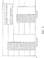
- a component produced through this cold spray process may exhibits strength in excess of an equivalent wrought counterpart ( Figure 2 ).
- the cold spray process disclosed herein selects the combination of particle temperature, velocity, and size that allows spraying at a temperature far below the melting point of the powdered metals which results in a layer 24 of particles in their solid state.
- the cold spray system 20 also offers significant advantages that minimize or eliminate the deleterious effects of high-temperature oxidation, evaporation, melting, crystallization, residual stresses, de-bonding, gas release, and other common problems of other additive manufacturing methods yet provides strong bond strength on coatings and substrates.
- the powdered metal may include one or more various ductile metals 26 such as Copper, Aluminum, steel alloys or others that plastically deform.
- the prime mover of the cold spray system 20 is an inert or semi-inert carrier gas 28 such as Helium, Nitrogen or Krypton that is non-oxidizing to the powdered metal particles.
- the velocity of the spray is inversely proportional to the molecular mass of the gas 28 such that a mixture of gasses may also be utilized to further control resultant temperatures and particle velocity.
- the desired velocity is great enough to break the oxide film on the powdered metal particles yet remain below the speed of sound through a convergent divergent nozzle 30.
- the temperature of the gas readily affects the velocity at which the speed of sound is reached. For example, a cold gas reaches the speed of sound at approximately 805 mph (360 m/s) while the same gas at approximately 1470F (800C) may be propelled at approximately 1118 mph (500 m/s).
- the carrier gas may be heated to temperatures of approximately 1470F (800C) with heater 32.
- the cold spray system 20 may be used as an Additive Manufacturing process to produce higher strength, lighter weight and consolidated components such as gear and shaft components through the layered deposition of powdered metals. It should be understood that although particular component types are illustrated in the disclosed non-limiting embodiment, other components will also benefit herefrom.
- the cold spray system 20 facilitates additive manufacturing through the deposition of powdered metals of multiple materials.
- the additive manufactured component may then be readily heat treated, and machined to final shape.
- a core 40 of a gear or shaft may be manufactured with low carbon steel alloy powder to provide high bending fatigue resistance, while an outer surface 42 such as gear teeth may be manufactured with a tool steel alloy powder to provide high wear resistance and high surface hardness.
- the additive manufactured near net shape may then be heat treated and machined in its hardened state to a final profile.
- An interface between the core 40 and the outer surface 42 need not be consistent. That is, the interface between the core 40 and the outer surface 42 may be delineated in response to expected loads, weight or other variables.
- a cold spray additive manufacture process 200 to additive manufacture a component is schematically illustrated.
- the additive manufacturing process constructs a component layer by layer from powdered metal.
- the powdered metal of each layer may be consolidated either by diffusion through melting via, for example, a laser or electron beam, or are bonded through plastic deformation of both substrate and powder metal particle layers that provide intimate conformal contact from the high local pressures generated by the cold spray system 20.
- Step 202 a preliminary design of a near net shape component is proposed (Step 202). That is, models are developed to optimize the near net shape component design to be manufactured with cold spray additive manufacturing.
- a substrate 44 ( Figure 3 ) is manufactured to provide, for example, a mandrel- like shape to initiate the cold spray process.
- the substrate may, for example, provide an outer diameter that becomes a gear shaft inner diameter of the near net shape component (Step 204).
- the near net shape component design may then be optimized with, for example, OptiStruct Topology optimization software manufactured by Altair Engineering, Inc.
- the optimization constraints may include a 25% increase in the material mechanical properties, increased surface resistance to fatigue and wear with a stronger material such as tool steel, reduce component weight without stress state increase and enhanced performance.
- One example output of the optimization analysis is to reduce weight of a near net shape gear (RELATED ART; Figure 5 ) (Step 206; Figure 6 ).
- Another optimization analysis may be directed to a low cost gear.
- a third optimization analysis may be directed to increase the fatigue strength of the near net shape component.
- finite element modeling of the cold spray process may be used to optimize the process parameters such as powdered material initial temperature, critical velocity, and powder size to facilitate cold spraying at a temperature below the melting point of the metal materials.
- the desired velocity is greater than the critical velocity necessary to achieve a successful deposition in their solid state.
- Models may then be used to identify the optimum powder deposition path for each material to insure proper bonding of the particles (Step 208). This model may also be used to support the selection of nozzle 30 geometry to increase the efficiency of the deposition process. The near net shape is then produced via the cold spray process on the substrate (Step 210).
- the heat treatment of the near net shape may also be simulated with finite element analysis to define the heating temperature and cooling rate for the selected carbon steel and tool steel material properties (Step 212).
- the produced near net shape component is then heat treated to achieve the required properties (Step 214). No carburization heat treatment cycle is required since tool steel material is utilized at the tooth surface.
- the core substrate 44 is then melted and removed (Step 216). That is, the substrate 44 upon which the cold spray additive manufacturing is initiated is removed.
- Optimum machining parameters and cutter paths are then identified to generate the final tooth profile (Step 218). Because the surface hardness after heat treatment is greater than 60 Rc in the disclosed non-limiting embodiment, the final process is to use hard turning technologies and ceramic or cubic boron nitride tools to machine the gear teeth to the final profile.
- the shaft 46 ( Figure 3 ) may then be machined to final dimensions (Step 220).
Landscapes
- Chemical & Material Sciences (AREA)
- Engineering & Computer Science (AREA)
- Mechanical Engineering (AREA)
- Materials Engineering (AREA)
- Manufacturing & Machinery (AREA)
- Metallurgy (AREA)
- Organic Chemistry (AREA)
- Thermal Sciences (AREA)
- Physics & Mathematics (AREA)
- General Engineering & Computer Science (AREA)
- Chemical Kinetics & Catalysis (AREA)
- Crystallography & Structural Chemistry (AREA)
- Composite Materials (AREA)
- Electromagnetism (AREA)
- Powder Metallurgy (AREA)
- Other Surface Treatments For Metallic Materials (AREA)
- Gears, Cams (AREA)
Abstract
Description
- The present disclosure relates generally to powdered additive manufacturing applications of functionally graded structure and materials.
- Gear manufacturing is one of the most complicated manufacture processes. The selection of gear materials require controlled hardenability, minimal non-metallic inclusions especially oxides, good formability for better forge die life and consistency of forge quality, good machinability, low quench distortion and minimal grain growth during high temperature carburization. Gear steel processes and chemical compositions that reduce inter-granular oxidation through the development of secondary refining are also relatively expensive.
- To produce one gear, wide ranges of operations of between 50 to 160 steps are often required dependent on the application, e.g., general or aerospace. Current gear manufacture processes, such as casting, extrusion, or forging, in addition to carburization, heat treatments and machining may require relatively high energy consumption, high tooling cost for initial production and relatively long lead times for the raw material
- A component according to one disclosed non-limiting embodiment of the present disclosure includes a cold sprayed additive manufactured core and a cold sprayed additive manufactured set of teeth around the core.
- A further embodiment of the foregoing embodiment of the present disclosure wherein the core is manufactured of a carbon steel alloy powder.
- In the alternative or additionally thereto, the foregoing embodiment wherein the set of teeth is manufactured of a tool steel alloy powder.
- A further embodiment of any of the foregoing embodiments, of the present disclosure wherein the core and the set of teeth are manufactured as a near net shape.
- A further embodiment of any of the foregoing embodiments, of the present disclosure wherein the set of teeth is manufactured of a tool steel alloy powder.
- A further embodiment of any of the foregoing embodiments, of the present disclosure wherein the component is a gear.
- In the alternative or additionally thereto, the foregoing embodiment wherein the gear is at least partially hollow.
- A method of manufacturing a component according to one disclosed non-limiting embodiment of the present disclosure includes spraying a powdered metal to form an additive manufactured core; and spraying a powdered metal to form an additive manufactured set of teeth around the core.
- A further embodiment of the foregoing embodiment of the present disclosure includes cold spraying the powdered metal to form the additive manufactured core onto a substrate.
- In the alternative or additionally thereto, the foregoing embodiment includes removing the substrate.
- In the alternative or additionally thereto, the foregoing embodiment includes spraying the powdered metal to accelerate and plastically deform the powdered metal.
- In the alternative or additionally thereto, the foregoing embodiment includes generating high strain rate plasticity.
- In the alternative or additionally thereto, the foregoing embodiment includes spraying the powdered metal via a cold spray system.
- In the alternative or additionally thereto, the foregoing embodiment includes heat-treating the additive manufactured set of teeth.
- In the alternative or additionally thereto, the foregoing embodiment includes final machining the additive manufactured set of teeth.
- Various features will become apparent to those skilled in the art from the following detailed description of the disclosed non-limiting embodiment. The drawings that accompany the detailed description can be briefly described as follows:
-
Figure 1 is a general schematic view of an exemplary cold spray system; -
Figure 2 is an comparison between a cold sprayed additive manufacturing component and an equivalent conventional wrought component; -
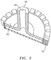
Figure 3 is a partial sectional view of a cold sprayed additive manufacturing component that is manufactured with low alloy steel and tool steel outer layer; -
Figure 4 is a flow diagram of an integrated design / additive manufacturing approach to produce an additively manufactured functionally graded gear according to one disclosed non-limiting embodiment; -
Figure 5 represent the conventional RELATED ART design of an aerospace gear; and. -
Figure 6 represent the gear ofFigure 5 after utilizing topology optimization method to reduce weight without sacrificing. -
Figure 1 schematically illustrates a cold spray system 20 that is utilized to produce dense powdered metal components that incorporate high levels of work into the process of densification. Cold gas-dynamic spraying (cold spray) may be utilized as an Additive Manufacturing (AM) process. Significantly higher strength through recrystallization and micro structure refinement is provided via the cold spray system 20 as other powder processes cannot produce the level of working and thus the mechanical properties of this process. One example cold spray system 20 is that manufactured by, for example, Sulzer Metco Kinetiks™ 4000 Cold Spray Gun. - The cold spray system 20 exposes a
metallic substrate 22 to a high velocity 671-3355 mph (300-1500 m/s) jet of relatively small 0.00004-0.0039 inches (1-100 µ_η) powdered metal particles accelerated by a supersonic jet of compressed gas. The cold spray system 20 accelerates the powdered metals toward the substrate such that the powdered metal particles deform on impact to generate high strain rate plasticity. This plasticity works the powdered metals, densities the structure, and due to the high strain rate of the process, recrystallizes nano-grains in the deposited material. Experiments have shown that a component produced through this cold spray process may exhibits strength in excess of an equivalent wrought counterpart (Figure 2 ). - The cold spray process disclosed herein selects the combination of particle temperature, velocity, and size that allows spraying at a temperature far below the melting point of the powdered metals which results in a layer 24 of particles in their solid state. The cold spray system 20 also offers significant advantages that minimize or eliminate the deleterious effects of high-temperature oxidation, evaporation, melting, crystallization, residual stresses, de-bonding, gas release, and other common problems of other additive manufacturing methods yet provides strong bond strength on coatings and substrates.
- In one disclosed non-limiting embodiment, the powdered metal may include one or more various ductile metals 26 such as Copper, Aluminum, steel alloys or others that plastically deform. The prime mover of the cold spray system 20 is an inert or semi-inert carrier gas 28 such as Helium, Nitrogen or Krypton that is non-oxidizing to the powdered metal particles.
- The velocity of the spray is inversely proportional to the molecular mass of the gas 28 such that a mixture of gasses may also be utilized to further control resultant temperatures and particle velocity. Generally, the desired velocity is great enough to break the oxide film on the powdered metal particles yet remain below the speed of sound through a convergent divergent nozzle 30. Furthermore, the temperature of the gas readily affects the velocity at which the speed of sound is reached. For example, a cold gas reaches the speed of sound at approximately 805 mph (360 m/s) while the same gas at approximately 1470F (800C) may be propelled at approximately 1118 mph (500 m/s). In one example, the carrier gas may be heated to temperatures of approximately 1470F (800C) with heater 32.
- The cold spray system 20 may be used as an Additive Manufacturing process to produce higher strength, lighter weight and consolidated components such as gear and shaft components through the layered deposition of powdered metals. It should be understood that although particular component types are illustrated in the disclosed non-limiting embodiment, other components will also benefit herefrom.
- The cold spray system 20 facilitates additive manufacturing through the deposition of powdered metals of multiple materials. The additive manufactured component may then be readily heat treated, and machined to final shape.
- With reference to
Figure 3 , in one disclosed non-limiting embodiment, two or more different powdered metals may be utilized. For example only, acore 40 of a gear or shaft may be manufactured with low carbon steel alloy powder to provide high bending fatigue resistance, while anouter surface 42 such as gear teeth may be manufactured with a tool steel alloy powder to provide high wear resistance and high surface hardness. The additive manufactured near net shape may then be heat treated and machined in its hardened state to a final profile. - An interface between the
core 40 and theouter surface 42 need not be consistent. That is, the interface between thecore 40 and theouter surface 42 may be delineated in response to expected loads, weight or other variables. - With reference to
Figure 4 , a cold sprayadditive manufacture process 200 to additive manufacture a component is schematically illustrated. The additive manufacturing process constructs a component layer by layer from powdered metal. The powdered metal of each layer may be consolidated either by diffusion through melting via, for example, a laser or electron beam, or are bonded through plastic deformation of both substrate and powder metal particle layers that provide intimate conformal contact from the high local pressures generated by the cold spray system 20. - Initially, a preliminary design of a near net shape component is proposed (Step 202). That is, models are developed to optimize the near net shape component design to be manufactured with cold spray additive manufacturing.
- A substrate 44 (
Figure 3 ) is manufactured to provide, for example, a mandrel- like shape to initiate the cold spray process. The substrate may, for example, provide an outer diameter that becomes a gear shaft inner diameter of the near net shape component (Step 204). - The near net shape component design may then be optimized with, for example, OptiStruct Topology optimization software manufactured by Altair Engineering, Inc. The optimization constraints may include a 25% increase in the material mechanical properties, increased surface resistance to fatigue and wear with a stronger material such as tool steel, reduce component weight without stress state increase and enhanced performance. One example output of the optimization analysis is to reduce weight of a near net shape gear (RELATED ART;
Figure 5 ) (Step 206;Figure 6 ). Another optimization analysis may be directed to a low cost gear. A third optimization analysis may be directed to increase the fatigue strength of the near net shape component. - After near net shape component design optimization, finite element modeling of the cold spray process (modeling of the multiple splats deposition) may be used to optimize the process parameters such as powdered material initial temperature, critical velocity, and powder size to facilitate cold spraying at a temperature below the melting point of the metal materials. The desired velocity is greater than the critical velocity necessary to achieve a successful deposition in their solid state.
- Models may then be used to identify the optimum powder deposition path for each material to insure proper bonding of the particles (Step 208). This model may also be used to support the selection of nozzle 30 geometry to increase the efficiency of the deposition process. The near net shape is then produced via the cold spray process on the substrate (Step 210).
- The heat treatment of the near net shape may also be simulated with finite element analysis to define the heating temperature and cooling rate for the selected carbon steel and tool steel material properties (Step 212).
- The produced near net shape component is then heat treated to achieve the required properties (Step 214). No carburization heat treatment cycle is required since tool steel material is utilized at the tooth surface.
- The
core substrate 44 is then melted and removed (Step 216). That is, thesubstrate 44 upon which the cold spray additive manufacturing is initiated is removed. - Optimum machining parameters and cutter paths are then identified to generate the final tooth profile (Step 218). Because the surface hardness after heat treatment is greater than 60 Rc in the disclosed non-limiting embodiment, the final process is to use hard turning technologies and ceramic or cubic boron nitride tools to machine the gear teeth to the final profile. The shaft 46 (
Figure 3 ) may then be machined to final dimensions (Step 220). - Following this methodology, a cold spray additive manufacturing component has shown an increase in both ultimate tensile strength and yield by approximately 20%.
- Although the different non-limiting embodiments have specific illustrated components, the embodiments of this invention are not limited to those particular combinations. It is possible to use some of the components or features from any of the non-limiting embodiments in combination with features or components from any of the other non-limiting embodiments.
- It should be understood that like reference numerals identify corresponding or similar elements throughout the several drawings. It should also be understood that although a particular component arrangement is disclosed in the illustrated embodiment, other arrangements will benefit herefrom.
- Although the different non-limiting embodiments have specific illustrated components, the embodiments of this invention are not limited to those particular combinations. It is possible to use some of the components or features from any of the non-limiting embodiments in combination with features or components from any of the other non-limiting embodiments.
- Although particular step sequences are shown, described, and claimed, it should be understood that steps may be performed in any order, separated or combined unless otherwise indicated and will still benefit from the present disclosure.
- The foregoing description is exemplary rather than defined by the limitations within. Various non-limiting embodiments are disclosed herein, however, one of ordinary skill in the art would recognize that various modifications and variations in light of the above teachings will fall within the scope of the appended claims. It is therefore to be understood that within the scope of the appended claims, the disclosure may be practiced other than as specifically described. For that reason the appended claims should be studied to determine true scope and content.
Claims (14)
- A component comprising:a cold sprayed additive manufactured core material, the core material having a mandrel shape center to form a gear shaft inner diameter upon removal of a substrate ; anda cold sprayed additive manufactured set of teeth of different material around said core.
- The component as recited in claim 1, wherein said core is manufactured of a carbon steel alloy powder.
- The component as recited in claim 1 or 2, wherein said set of teeth is manufactured of a tool steel alloy powder.
- The component as recited in claim 1, 2 or 3 wherein said core and said set of teeth are manufactured as a near net shape.
- The component as recited in any preceding claim, wherein said component is a gear.
- The component as recited in claim 5, wherein said gear is at least partially hollow.
- A method of manufacturing a component comprising:spraying a powdered metal to form an additive manufactured corespraying a powdered metal to form an additive manufactured set of teeth around the core.
- The method as recited in claim 7, further comprising cold spraying the powdered metal to form the additive manufactured core onto a substrate.
- The method as recited in claim 8, further comprising removing the substrate.
- The method as recited in claim 7, 8 or 9, further comprising spraying the powdered metal to accelerate and plastically deform the powdered metal.
- The method as recited in any of claims 7 to 10, further comprising generating high strain rate plasticity.
- The method as recited in any of claims 7 to 11, further comprising spraying the powdered metal via a cold spray system.
- The method as recited in any of claims 7 to 12, further comprising heat-treating the additive manufactured set of teeth.
- The method as recited in any of claims 7 to 13, further comprising final machining the additive manufactured set of teeth.
Priority Applications (1)
| Application Number | Priority Date | Filing Date | Title |
|---|---|---|---|
| EP20167325.8A EP3696296B1 (en) | 2013-01-28 | 2013-01-28 | Structured material alloy component fabrication |
Applications Claiming Priority (3)
| Application Number | Priority Date | Filing Date | Title |
|---|---|---|---|
| EP13872443.0A EP2948569B1 (en) | 2013-01-28 | 2013-01-28 | Manufacturing of gear components by cold spraying |
| PCT/US2013/023428 WO2014116254A1 (en) | 2013-01-28 | 2013-01-28 | Structured material alloy component fabrication |
| EP20167325.8A EP3696296B1 (en) | 2013-01-28 | 2013-01-28 | Structured material alloy component fabrication |
Related Parent Applications (1)
| Application Number | Title | Priority Date | Filing Date |
|---|---|---|---|
| EP13872443.0A Division EP2948569B1 (en) | 2013-01-28 | 2013-01-28 | Manufacturing of gear components by cold spraying |
Publications (2)
| Publication Number | Publication Date |
|---|---|
| EP3696296A1 true EP3696296A1 (en) | 2020-08-19 |
| EP3696296B1 EP3696296B1 (en) | 2022-09-14 |
Family
ID=51227921
Family Applications (2)
| Application Number | Title | Priority Date | Filing Date |
|---|---|---|---|
| EP20167325.8A Active EP3696296B1 (en) | 2013-01-28 | 2013-01-28 | Structured material alloy component fabrication |
| EP13872443.0A Active EP2948569B1 (en) | 2013-01-28 | 2013-01-28 | Manufacturing of gear components by cold spraying |
Family Applications After (1)
| Application Number | Title | Priority Date | Filing Date |
|---|---|---|---|
| EP13872443.0A Active EP2948569B1 (en) | 2013-01-28 | 2013-01-28 | Manufacturing of gear components by cold spraying |
Country Status (4)
| Country | Link |
|---|---|
| US (2) | US10626974B2 (en) |
| EP (2) | EP3696296B1 (en) |
| AU (3) | AU2013375273B2 (en) |
| WO (1) | WO2014116254A1 (en) |
Cited By (1)
| Publication number | Priority date | Publication date | Assignee | Title |
|---|---|---|---|---|
| WO2022215061A3 (en) * | 2021-04-06 | 2022-11-24 | Eaton Intelligent Power Limited | Cold spray additive manufacturing of multi-material electrical contacts |
Families Citing this family (46)
| Publication number | Priority date | Publication date | Assignee | Title |
|---|---|---|---|---|
| US20150047463A1 (en) | 2012-06-26 | 2015-02-19 | California Institute Of Technology | Systems and methods for implementing bulk metallic glass-based macroscale gears |
| US20140342179A1 (en) | 2013-04-12 | 2014-11-20 | California Institute Of Technology | Systems and methods for shaping sheet materials that include metallic glass-based materials |
| CN104373548A (en) * | 2013-08-16 | 2015-02-25 | 德昌电机(深圳)有限公司 | Gear |
| US9958068B2 (en) * | 2014-03-21 | 2018-05-01 | Goodrich Corporation | Piston housing system and apparatus |
| US10151377B2 (en) | 2015-03-05 | 2018-12-11 | California Institute Of Technology | Systems and methods for implementing tailored metallic glass-based strain wave gears and strain wave gear components |
| US10174780B2 (en) | 2015-03-11 | 2019-01-08 | California Institute Of Technology | Systems and methods for structurally interrelating components using inserts made from metallic glass-based materials |
| US10155412B2 (en) | 2015-03-12 | 2018-12-18 | California Institute Of Technology | Systems and methods for implementing flexible members including integrated tools made from metallic glass-based materials |
| US10371244B2 (en) | 2015-04-09 | 2019-08-06 | United Technologies Corporation | Additive manufactured gear for a geared architecture gas turbine engine |
| EP3078436B1 (en) * | 2015-04-10 | 2024-06-12 | Richemont International Sa | Method for manufacturing a clock component |
| EP3310943A4 (en) | 2015-06-11 | 2018-08-22 | Effusiontech Pty Ltd | Apparatus and a method for forming 3d objects |
| DE102015218074A1 (en) * | 2015-09-21 | 2017-03-23 | Airbus Operations Gmbh | Connection system, connection arrangement and method |
| US10968527B2 (en) | 2015-11-12 | 2021-04-06 | California Institute Of Technology | Method for embedding inserts, fasteners and features into metal core truss panels |
| US20180326547A1 (en) * | 2015-11-30 | 2018-11-15 | The Gleason Works | Additive manufacturing of gears |
| US11248692B2 (en) * | 2016-03-11 | 2022-02-15 | Deere & Company | Composite gears and methods of manufacturing such gears |
| US20170355018A1 (en) * | 2016-06-09 | 2017-12-14 | Hamilton Sundstrand Corporation | Powder deposition for additive manufacturing |
| US10253785B2 (en) * | 2016-08-31 | 2019-04-09 | Unison Industries, Llc | Engine heat exchanger and method of forming |
| DE102016221889A1 (en) * | 2016-11-08 | 2018-05-09 | Brose Fahrzeugteile GmbH & Co. Kommanditgesellschaft, Würzburg | 3D printing device and 3D printing process |
| EP3323714B1 (en) * | 2016-11-21 | 2019-07-03 | Ratier-Figeac SAS | Propeller counterweight |
| US10519552B2 (en) * | 2016-12-22 | 2019-12-31 | United Technologies Corporation | Deposited material structure with integrated component |
| US11198181B2 (en) | 2017-03-10 | 2021-12-14 | California Institute Of Technology | Methods for fabricating strain wave gear flexsplines using metal additive manufacturing |
| RU2752692C2 (en) * | 2017-04-06 | 2021-07-29 | ЭФФЬЮЖНТЕК АйПи ПТИ. ЛТД. | Spraying device |
| GB201705979D0 (en) | 2017-04-13 | 2017-05-31 | Rolls Royce Plc | A Gear, a method of manufacturing a gear and a geared gas turbine engine |
| WO2018218077A1 (en) | 2017-05-24 | 2018-11-29 | California Institute Of Technology | Hypoeutectic amorphous metal-based materials for additive manufacturing |
| KR102493233B1 (en) | 2017-06-02 | 2023-01-27 | 캘리포니아 인스티튜트 오브 테크놀로지 | High-toughness metallic glass-based composites for additive manufacturing |
| EP3536822B1 (en) * | 2018-03-08 | 2023-02-15 | Hermle Maschinenbau GmbH | Method for producing a composite |
| CN108247043B (en) * | 2018-03-22 | 2024-04-02 | 顺德职业技术学院 | 3D printing method and equipment for cold spraying deposited metal capable of melting and removing support |
| US11333200B2 (en) * | 2018-06-21 | 2022-05-17 | General Electric Company | Method for manufacturing a pitch bearing or a yaw bearing of a wind turbine via additive manufacturing |
| US11173568B2 (en) * | 2018-07-11 | 2021-11-16 | GM Global Technology Operations LLC | Composite metal flexplate |
| US11313041B2 (en) | 2018-07-17 | 2022-04-26 | National Research Council Of Canada | Manufactured metal objects with hollow channels and method for fabrication thereof |
| DE102018120293A1 (en) * | 2018-08-21 | 2020-02-27 | Sascha Larch | Process for producing a lightweight tubular casing body and lightweight tubular casing body |
| WO2020038930A1 (en) | 2018-08-21 | 2020-02-27 | Sascha Larch | Method for producing a light-weight pressure tank and light-weight pressure tank |
| EP3696447A1 (en) | 2019-02-12 | 2020-08-19 | Siemens Aktiengesellschaft | Transmission element and method for producing same |
| US11680629B2 (en) | 2019-02-28 | 2023-06-20 | California Institute Of Technology | Low cost wave generators for metal strain wave gears and methods of manufacture thereof |
| US11859705B2 (en) | 2019-02-28 | 2024-01-02 | California Institute Of Technology | Rounded strain wave gear flexspline utilizing bulk metallic glass-based materials and methods of manufacture thereof |
| US11400613B2 (en) | 2019-03-01 | 2022-08-02 | California Institute Of Technology | Self-hammering cutting tool |
| US11591906B2 (en) | 2019-03-07 | 2023-02-28 | California Institute Of Technology | Cutting tool with porous regions |
| US11220751B2 (en) | 2019-06-24 | 2022-01-11 | Hamilton Sundstrand Corporation | Gear shaft and method of manufacturing |
| JP7380326B2 (en) * | 2020-02-28 | 2023-11-15 | セイコーエプソン株式会社 | gearing and robots |
| CN117980092A (en) * | 2021-08-31 | 2024-05-03 | 安德里茨公司 | 3D metal partial printing of the fine grinding machine section |
| CN113696478A (en) * | 2021-09-08 | 2021-11-26 | 昆明理工大学 | High-wear-resistance gear synthesized based on 3D printing technology |
| US12078234B2 (en) * | 2021-09-22 | 2024-09-03 | Beijing Institute Of Technology | Lightweight high load-bearing reducer and method for generating bionic bone structure of gear thereof |
| CN113996804B (en) * | 2021-10-21 | 2023-03-14 | 昆明理工大学 | Preparation method of partitioned gradient component gear |
| DE102022126742A1 (en) * | 2022-10-13 | 2024-04-18 | Bodenmüller Hörburger Schratt Antriebstechnik GmbH & Co. KG | Gearbox with shaft with additive pressure comb and method for producing a shaft |
| CN117620200A (en) * | 2023-12-14 | 2024-03-01 | 上海交通大学 | Metal heterogeneous material additive-isomaterial composite preparation and component construction and forming method |
| WO2025259589A1 (en) * | 2024-06-11 | 2025-12-18 | The Timken Company | Hybrid manufacturing of carbon or nitrogen-containing components |
| DE102024126112A1 (en) | 2024-09-11 | 2026-03-12 | Schaeffler Technologies AG & Co. KG | One-piece, additively manufactured component |
Citations (2)
| Publication number | Priority date | Publication date | Assignee | Title |
|---|---|---|---|---|
| WO1997022819A1 (en) * | 1995-12-15 | 1997-06-26 | Zenith Sintered Products, Inc. | Duplex sprocket/gear construction and method of making same |
| US7967924B2 (en) * | 2005-05-17 | 2011-06-28 | General Electric Company | Method for making a compositionally graded gas turbine disk |
Family Cites Families (22)
| Publication number | Priority date | Publication date | Assignee | Title |
|---|---|---|---|---|
| US2445583A (en) * | 1945-03-28 | 1948-07-20 | Carnegie Illinois Steel Corp | Method and apparatus for casting metals |
| DE3637386C1 (en) * | 1986-11-03 | 1987-09-24 | Neuenstein Zahnradwerk | Method and device for producing synchronization bodies in gearboxes of motor vehicles |
| DE3705658A1 (en) * | 1987-02-21 | 1988-09-08 | Neuenstein Zahnradwerk | METHOD FOR PRODUCING A FRICTION RING WITH A CONICAL OR CYLINDRICAL FRICTION SURFACE |
| WO1991019016A1 (en) * | 1990-05-19 | 1991-12-12 | Institut Teoreticheskoi I Prikladnoi Mekhaniki Sibirskogo Otdelenia Akademii Nauk Sssr | Method and device for coating |
| KR0134666Y1 (en) * | 1996-08-30 | 1999-02-18 | 안문휘 | Connection structure of roofing panel |
| AR007698A1 (en) * | 1996-08-28 | 1999-11-10 | Deere & Co | METHOD TO CONTRIBUTE SURFACE HARDNESS TO A METALLIC SURFACE AND A MUD PREPARED BY SUCH METHOD |
| AT407290B (en) * | 1998-03-03 | 2001-02-26 | Hoerbiger & Co | FRICTION CLUTCH OR BRAKE |
| US6471800B2 (en) * | 2000-11-29 | 2002-10-29 | Nanotek Instruments, Inc. | Layer-additive method and apparatus for freeform fabrication of 3-D objects |
| US6905728B1 (en) * | 2004-03-22 | 2005-06-14 | Honeywell International, Inc. | Cold gas-dynamic spray repair on gas turbine engine components |
| EP1829988A1 (en) * | 2006-03-02 | 2007-09-05 | Praxair Surface Technologies GmbH | Method of repairing and refurbishing an aluminum component under dynamic loading for airfoil equipments |
| US8293035B2 (en) * | 2006-10-12 | 2012-10-23 | Air Products And Chemicals, Inc. | Treatment method, system and product |
| US20110223053A1 (en) | 2008-03-06 | 2011-09-15 | Commonwealth Scientific And Industrial Research Organisation | Manufacture of pipes |
| US8261444B2 (en) * | 2009-10-07 | 2012-09-11 | General Electric Company | Turbine rotor fabrication using cold spraying |
| WO2011157415A1 (en) * | 2010-06-15 | 2011-12-22 | Mxc Gmbh | Sprocket |
| US9101979B2 (en) * | 2011-10-31 | 2015-08-11 | California Institute Of Technology | Methods for fabricating gradient alloy articles with multi-functional properties |
| US10099322B2 (en) * | 2012-10-29 | 2018-10-16 | South Dakota Board Of Regents | Methods for cold spray repair |
| CH707326B1 (en) * | 2012-12-13 | 2018-06-15 | Cartier Int Ag | Mobile watchmaker for mysterious watch. |
| US9579718B2 (en) * | 2013-01-24 | 2017-02-28 | California Institute Of Technology | Systems and methods for fabricating objects including amorphous metal using techniques akin to additive manufacturing |
| US9566671B2 (en) * | 2013-05-22 | 2017-02-14 | Eaton Capital | Method for manufacturing a forging |
| US9673381B2 (en) * | 2014-07-22 | 2017-06-06 | Haidou WANG | Lead titanate coating and preparing method thereof |
| US9700957B1 (en) * | 2014-09-25 | 2017-07-11 | Steven P. Burgess | Methods of fabricating reduced weight components |
| CA2915896C (en) * | 2015-01-13 | 2021-08-03 | Rolls-Royce Corporation | Cone brake friction surface coating |
-
2013
- 2013-01-28 EP EP20167325.8A patent/EP3696296B1/en active Active
- 2013-01-28 US US14/763,896 patent/US10626974B2/en active Active
- 2013-01-28 EP EP13872443.0A patent/EP2948569B1/en active Active
- 2013-01-28 AU AU2013375273A patent/AU2013375273B2/en active Active
- 2013-01-28 WO PCT/US2013/023428 patent/WO2014116254A1/en not_active Ceased
-
2017
- 2017-11-24 AU AU2017265161A patent/AU2017265161B2/en active Active
-
2020
- 2020-01-21 AU AU2020200405A patent/AU2020200405A1/en not_active Abandoned
- 2020-03-11 US US16/815,502 patent/US11415210B2/en active Active
Patent Citations (2)
| Publication number | Priority date | Publication date | Assignee | Title |
|---|---|---|---|---|
| WO1997022819A1 (en) * | 1995-12-15 | 1997-06-26 | Zenith Sintered Products, Inc. | Duplex sprocket/gear construction and method of making same |
| US7967924B2 (en) * | 2005-05-17 | 2011-06-28 | General Electric Company | Method for making a compositionally graded gas turbine disk |
Cited By (3)
| Publication number | Priority date | Publication date | Assignee | Title |
|---|---|---|---|---|
| WO2022215061A3 (en) * | 2021-04-06 | 2022-11-24 | Eaton Intelligent Power Limited | Cold spray additive manufacturing of multi-material electrical contacts |
| US11951542B2 (en) | 2021-04-06 | 2024-04-09 | Eaton Intelligent Power Limited | Cold spray additive manufacturing of multi-material electrical contacts |
| US12611712B2 (en) | 2021-04-06 | 2026-04-28 | Eaton Intelligent Power Limited | Cold spray additive manufacturing of multi-material electrical contacts |
Also Published As
| Publication number | Publication date |
|---|---|
| EP2948569A1 (en) | 2015-12-02 |
| AU2013375273B2 (en) | 2017-08-31 |
| US10626974B2 (en) | 2020-04-21 |
| WO2014116254A1 (en) | 2014-07-31 |
| US20150323053A1 (en) | 2015-11-12 |
| AU2013375273A1 (en) | 2015-08-13 |
| US11415210B2 (en) | 2022-08-16 |
| EP2948569B1 (en) | 2020-04-22 |
| AU2017265161A1 (en) | 2017-12-21 |
| EP3696296B1 (en) | 2022-09-14 |
| AU2020200405A1 (en) | 2020-02-13 |
| US20200208726A1 (en) | 2020-07-02 |
| AU2017265161B2 (en) | 2019-10-24 |
| EP2948569A4 (en) | 2016-03-02 |
Similar Documents
| Publication | Publication Date | Title |
|---|---|---|
| US11415210B2 (en) | Structured material alloy component fabrication | |
| US20150321217A1 (en) | Solid state metal powder consolidation for structural components | |
| US7066235B2 (en) | Method for manufacturing clad components | |
| Li et al. | Solid-state additive manufacturing and repairing by cold spraying: A review | |
| JP5791882B2 (en) | Fabrication of turbine rotor using cold spraying | |
| US12377465B2 (en) | Complex concentrated alloy and high entropy alloy additive manufacturing systems and methods | |
| US7479299B2 (en) | Methods of forming high strength coatings | |
| EP2688708B1 (en) | Method for repairing an aluminium alloy component | |
| EP2564980A2 (en) | Solid state system and method for refurbishment of forged components | |
| US20150224743A1 (en) | Additively manufactured article | |
| EP3357605A1 (en) | Manufacturing method and post-processing treatment | |
| CN108884518A (en) | The HCP material of aluminium, titanium and zirconium and the product being made from it | |
| CN113423974A (en) | Transmission element and method for producing a transmission element | |
| JP6039355B2 (en) | Titanium aluminide construction method and product having titanium aluminide surface | |
| US20030217791A1 (en) | Method for producing a component and/or a coating comprised of a vibration-damping alloy or intermetallic compound, and component produced using this method | |
| WO2019040509A1 (en) | Multi-material components and methods of making the same | |
| Bambach et al. | Hot working behavior of selective laser melted and laser metal deposited Inconel 718 | |
| CN113260731A (en) | method of making a core | |
| JPH10156554A (en) | Metal clad titanium aluminide and method for producing the same | |
| JP2002263859A (en) | Holding jig for manufacturing diffusion bonding machine parts |
Legal Events
| Date | Code | Title | Description |
|---|---|---|---|
| PUAI | Public reference made under article 153(3) epc to a published international application that has entered the european phase |
Free format text: ORIGINAL CODE: 0009012 |
|
| STAA | Information on the status of an ep patent application or granted ep patent |
Free format text: STATUS: THE APPLICATION HAS BEEN PUBLISHED |
|
| AC | Divisional application: reference to earlier application |
Ref document number: 2948569 Country of ref document: EP Kind code of ref document: P |
|
| AK | Designated contracting states |
Kind code of ref document: A1 Designated state(s): AL AT BE BG CH CY CZ DE DK EE ES FI FR GB GR HR HU IE IS IT LI LT LU LV MC MK MT NL NO PL PT RO RS SE SI SK SM TR |
|
| RIN1 | Information on inventor provided before grant (corrected) |
Inventor name: NARDI, AARON T. Inventor name: GU, WENJIONG Inventor name: REEVE, HAYDEN M. Inventor name: AMIS, ERIC Inventor name: VIENS, DANIEL V. Inventor name: EL-WARDANY, TAHANY I. |
|
| STAA | Information on the status of an ep patent application or granted ep patent |
Free format text: STATUS: REQUEST FOR EXAMINATION WAS MADE |
|
| RAP1 | Party data changed (applicant data changed or rights of an application transferred) |
Owner name: RAYTHEON TECHNOLOGIES CORPORATION |
|
| 17P | Request for examination filed |
Effective date: 20210219 |
|
| RBV | Designated contracting states (corrected) |
Designated state(s): AL AT BE BG CH CY CZ DE DK EE ES FI FR GB GR HR HU IE IS IT LI LT LU LV MC MK MT NL NO PL PT RO RS SE SI SK SM TR |
|
| GRAP | Despatch of communication of intention to grant a patent |
Free format text: ORIGINAL CODE: EPIDOSNIGR1 |
|
| STAA | Information on the status of an ep patent application or granted ep patent |
Free format text: STATUS: GRANT OF PATENT IS INTENDED |
|
| INTG | Intention to grant announced |
Effective date: 20220329 |
|
| GRAS | Grant fee paid |
Free format text: ORIGINAL CODE: EPIDOSNIGR3 |
|
| GRAA | (expected) grant |
Free format text: ORIGINAL CODE: 0009210 |
|
| STAA | Information on the status of an ep patent application or granted ep patent |
Free format text: STATUS: THE PATENT HAS BEEN GRANTED |
|
| AC | Divisional application: reference to earlier application |
Ref document number: 2948569 Country of ref document: EP Kind code of ref document: P |
|
| AK | Designated contracting states |
Kind code of ref document: B1 Designated state(s): AL AT BE BG CH CY CZ DE DK EE ES FI FR GB GR HR HU IE IS IT LI LT LU LV MC MK MT NL NO PL PT RO RS SE SI SK SM TR |
|
| REG | Reference to a national code |
Ref country code: GB Ref legal event code: FG4D |
|
| REG | Reference to a national code |
Ref country code: CH Ref legal event code: EP |
|
| REG | Reference to a national code |
Ref country code: DE Ref legal event code: R096 Ref document number: 602013082538 Country of ref document: DE |
|
| REG | Reference to a national code |
Ref country code: IE Ref legal event code: FG4D |
|
| REG | Reference to a national code |
Ref country code: AT Ref legal event code: REF Ref document number: 1518739 Country of ref document: AT Kind code of ref document: T Effective date: 20221015 |
|
| REG | Reference to a national code |
Ref country code: LT Ref legal event code: MG9D |
|
| REG | Reference to a national code |
Ref country code: NL Ref legal event code: MP Effective date: 20220914 |
|
| PG25 | Lapsed in a contracting state [announced via postgrant information from national office to epo] |
Ref country code: SE Free format text: LAPSE BECAUSE OF FAILURE TO SUBMIT A TRANSLATION OF THE DESCRIPTION OR TO PAY THE FEE WITHIN THE PRESCRIBED TIME-LIMIT Effective date: 20220914 Ref country code: RS Free format text: LAPSE BECAUSE OF FAILURE TO SUBMIT A TRANSLATION OF THE DESCRIPTION OR TO PAY THE FEE WITHIN THE PRESCRIBED TIME-LIMIT Effective date: 20220914 Ref country code: NO Free format text: LAPSE BECAUSE OF FAILURE TO SUBMIT A TRANSLATION OF THE DESCRIPTION OR TO PAY THE FEE WITHIN THE PRESCRIBED TIME-LIMIT Effective date: 20221214 Ref country code: LV Free format text: LAPSE BECAUSE OF FAILURE TO SUBMIT A TRANSLATION OF THE DESCRIPTION OR TO PAY THE FEE WITHIN THE PRESCRIBED TIME-LIMIT Effective date: 20220914 Ref country code: LT Free format text: LAPSE BECAUSE OF FAILURE TO SUBMIT A TRANSLATION OF THE DESCRIPTION OR TO PAY THE FEE WITHIN THE PRESCRIBED TIME-LIMIT Effective date: 20220914 Ref country code: FI Free format text: LAPSE BECAUSE OF FAILURE TO SUBMIT A TRANSLATION OF THE DESCRIPTION OR TO PAY THE FEE WITHIN THE PRESCRIBED TIME-LIMIT Effective date: 20220914 |
|
| REG | Reference to a national code |
Ref country code: AT Ref legal event code: MK05 Ref document number: 1518739 Country of ref document: AT Kind code of ref document: T Effective date: 20220914 |
|
| PG25 | Lapsed in a contracting state [announced via postgrant information from national office to epo] |
Ref country code: HR Free format text: LAPSE BECAUSE OF FAILURE TO SUBMIT A TRANSLATION OF THE DESCRIPTION OR TO PAY THE FEE WITHIN THE PRESCRIBED TIME-LIMIT Effective date: 20220914 Ref country code: GR Free format text: LAPSE BECAUSE OF FAILURE TO SUBMIT A TRANSLATION OF THE DESCRIPTION OR TO PAY THE FEE WITHIN THE PRESCRIBED TIME-LIMIT Effective date: 20221215 |
|
| PG25 | Lapsed in a contracting state [announced via postgrant information from national office to epo] |
Ref country code: SM Free format text: LAPSE BECAUSE OF FAILURE TO SUBMIT A TRANSLATION OF THE DESCRIPTION OR TO PAY THE FEE WITHIN THE PRESCRIBED TIME-LIMIT Effective date: 20220914 Ref country code: RO Free format text: LAPSE BECAUSE OF FAILURE TO SUBMIT A TRANSLATION OF THE DESCRIPTION OR TO PAY THE FEE WITHIN THE PRESCRIBED TIME-LIMIT Effective date: 20220914 Ref country code: PT Free format text: LAPSE BECAUSE OF FAILURE TO SUBMIT A TRANSLATION OF THE DESCRIPTION OR TO PAY THE FEE WITHIN THE PRESCRIBED TIME-LIMIT Effective date: 20230116 Ref country code: ES Free format text: LAPSE BECAUSE OF FAILURE TO SUBMIT A TRANSLATION OF THE DESCRIPTION OR TO PAY THE FEE WITHIN THE PRESCRIBED TIME-LIMIT Effective date: 20220914 Ref country code: CZ Free format text: LAPSE BECAUSE OF FAILURE TO SUBMIT A TRANSLATION OF THE DESCRIPTION OR TO PAY THE FEE WITHIN THE PRESCRIBED TIME-LIMIT Effective date: 20220914 Ref country code: AT Free format text: LAPSE BECAUSE OF FAILURE TO SUBMIT A TRANSLATION OF THE DESCRIPTION OR TO PAY THE FEE WITHIN THE PRESCRIBED TIME-LIMIT Effective date: 20220914 |
|
| PG25 | Lapsed in a contracting state [announced via postgrant information from national office to epo] |
Ref country code: SK Free format text: LAPSE BECAUSE OF FAILURE TO SUBMIT A TRANSLATION OF THE DESCRIPTION OR TO PAY THE FEE WITHIN THE PRESCRIBED TIME-LIMIT Effective date: 20220914 Ref country code: PL Free format text: LAPSE BECAUSE OF FAILURE TO SUBMIT A TRANSLATION OF THE DESCRIPTION OR TO PAY THE FEE WITHIN THE PRESCRIBED TIME-LIMIT Effective date: 20220914 Ref country code: IS Free format text: LAPSE BECAUSE OF FAILURE TO SUBMIT A TRANSLATION OF THE DESCRIPTION OR TO PAY THE FEE WITHIN THE PRESCRIBED TIME-LIMIT Effective date: 20230114 Ref country code: EE Free format text: LAPSE BECAUSE OF FAILURE TO SUBMIT A TRANSLATION OF THE DESCRIPTION OR TO PAY THE FEE WITHIN THE PRESCRIBED TIME-LIMIT Effective date: 20220914 |
|
| REG | Reference to a national code |
Ref country code: DE Ref legal event code: R097 Ref document number: 602013082538 Country of ref document: DE |
|
| P01 | Opt-out of the competence of the unified patent court (upc) registered |
Effective date: 20230521 |
|
| PG25 | Lapsed in a contracting state [announced via postgrant information from national office to epo] |
Ref country code: NL Free format text: LAPSE BECAUSE OF FAILURE TO SUBMIT A TRANSLATION OF THE DESCRIPTION OR TO PAY THE FEE WITHIN THE PRESCRIBED TIME-LIMIT Effective date: 20220914 Ref country code: AL Free format text: LAPSE BECAUSE OF FAILURE TO SUBMIT A TRANSLATION OF THE DESCRIPTION OR TO PAY THE FEE WITHIN THE PRESCRIBED TIME-LIMIT Effective date: 20220914 |
|
| PLBE | No opposition filed within time limit |
Free format text: ORIGINAL CODE: 0009261 |
|
| STAA | Information on the status of an ep patent application or granted ep patent |
Free format text: STATUS: NO OPPOSITION FILED WITHIN TIME LIMIT |
|
| PG25 | Lapsed in a contracting state [announced via postgrant information from national office to epo] |
Ref country code: DK Free format text: LAPSE BECAUSE OF FAILURE TO SUBMIT A TRANSLATION OF THE DESCRIPTION OR TO PAY THE FEE WITHIN THE PRESCRIBED TIME-LIMIT Effective date: 20220914 |
|
| 26N | No opposition filed |
Effective date: 20230615 |
|
| PG25 | Lapsed in a contracting state [announced via postgrant information from national office to epo] |
Ref country code: SI Free format text: LAPSE BECAUSE OF FAILURE TO SUBMIT A TRANSLATION OF THE DESCRIPTION OR TO PAY THE FEE WITHIN THE PRESCRIBED TIME-LIMIT Effective date: 20220914 |
|
| REG | Reference to a national code |
Ref country code: CH Ref legal event code: PL |
|
| PG25 | Lapsed in a contracting state [announced via postgrant information from national office to epo] |
Ref country code: LU Free format text: LAPSE BECAUSE OF NON-PAYMENT OF DUE FEES Effective date: 20230128 |
|
| REG | Reference to a national code |
Ref country code: BE Ref legal event code: MM Effective date: 20230131 |
|
| PG25 | Lapsed in a contracting state [announced via postgrant information from national office to epo] |
Ref country code: LI Free format text: LAPSE BECAUSE OF NON-PAYMENT OF DUE FEES Effective date: 20230131 Ref country code: CH Free format text: LAPSE BECAUSE OF NON-PAYMENT OF DUE FEES Effective date: 20230131 |
|
| PG25 | Lapsed in a contracting state [announced via postgrant information from national office to epo] |
Ref country code: BE Free format text: LAPSE BECAUSE OF NON-PAYMENT OF DUE FEES Effective date: 20230131 |
|
| PG25 | Lapsed in a contracting state [announced via postgrant information from national office to epo] |
Ref country code: IE Free format text: LAPSE BECAUSE OF NON-PAYMENT OF DUE FEES Effective date: 20230128 |
|
| PG25 | Lapsed in a contracting state [announced via postgrant information from national office to epo] |
Ref country code: IT Free format text: LAPSE BECAUSE OF FAILURE TO SUBMIT A TRANSLATION OF THE DESCRIPTION OR TO PAY THE FEE WITHIN THE PRESCRIBED TIME-LIMIT Effective date: 20220914 |
|
| PG25 | Lapsed in a contracting state [announced via postgrant information from national office to epo] |
Ref country code: MC Free format text: LAPSE BECAUSE OF FAILURE TO SUBMIT A TRANSLATION OF THE DESCRIPTION OR TO PAY THE FEE WITHIN THE PRESCRIBED TIME-LIMIT Effective date: 20220914 |
|
| PG25 | Lapsed in a contracting state [announced via postgrant information from national office to epo] |
Ref country code: MC Free format text: LAPSE BECAUSE OF FAILURE TO SUBMIT A TRANSLATION OF THE DESCRIPTION OR TO PAY THE FEE WITHIN THE PRESCRIBED TIME-LIMIT Effective date: 20220914 |
|
| PG25 | Lapsed in a contracting state [announced via postgrant information from national office to epo] |
Ref country code: BG Free format text: LAPSE BECAUSE OF FAILURE TO SUBMIT A TRANSLATION OF THE DESCRIPTION OR TO PAY THE FEE WITHIN THE PRESCRIBED TIME-LIMIT Effective date: 20220914 |
|
| PG25 | Lapsed in a contracting state [announced via postgrant information from national office to epo] |
Ref country code: BG Free format text: LAPSE BECAUSE OF FAILURE TO SUBMIT A TRANSLATION OF THE DESCRIPTION OR TO PAY THE FEE WITHIN THE PRESCRIBED TIME-LIMIT Effective date: 20220914 |
|
| PG25 | Lapsed in a contracting state [announced via postgrant information from national office to epo] |
Ref country code: CY Free format text: LAPSE BECAUSE OF FAILURE TO SUBMIT A TRANSLATION OF THE DESCRIPTION OR TO PAY THE FEE WITHIN THE PRESCRIBED TIME-LIMIT; INVALID AB INITIO Effective date: 20130128 |
|
| PG25 | Lapsed in a contracting state [announced via postgrant information from national office to epo] |
Ref country code: HU Free format text: LAPSE BECAUSE OF FAILURE TO SUBMIT A TRANSLATION OF THE DESCRIPTION OR TO PAY THE FEE WITHIN THE PRESCRIBED TIME-LIMIT; INVALID AB INITIO Effective date: 20130128 |
|
| REG | Reference to a national code |
Ref country code: DE Ref legal event code: R081 Ref document number: 602013082538 Country of ref document: DE Owner name: RTX CORPORATION (N.D.GES.D. STAATES DELAWARE),, US Free format text: FORMER OWNER: RAYTHEON TECHNOLOGIES CORPORATION, FARMINGTON, CT, US |
|
| PG25 | Lapsed in a contracting state [announced via postgrant information from national office to epo] |
Ref country code: TR Free format text: LAPSE BECAUSE OF FAILURE TO SUBMIT A TRANSLATION OF THE DESCRIPTION OR TO PAY THE FEE WITHIN THE PRESCRIBED TIME-LIMIT Effective date: 20220914 |
|
| PGFP | Annual fee paid to national office [announced via postgrant information from national office to epo] |
Ref country code: GB Payment date: 20251220 Year of fee payment: 14 |
|
| PGFP | Annual fee paid to national office [announced via postgrant information from national office to epo] |
Ref country code: FR Payment date: 20251217 Year of fee payment: 14 |
|
| PGFP | Annual fee paid to national office [announced via postgrant information from national office to epo] |
Ref country code: DE Payment date: 20251217 Year of fee payment: 14 |