EP3696036A1 - Method and device for controlling hybrid vehicle - Google Patents
Method and device for controlling hybrid vehicle Download PDFInfo
- Publication number
- EP3696036A1 EP3696036A1 EP17928635.6A EP17928635A EP3696036A1 EP 3696036 A1 EP3696036 A1 EP 3696036A1 EP 17928635 A EP17928635 A EP 17928635A EP 3696036 A1 EP3696036 A1 EP 3696036A1
- Authority
- EP
- European Patent Office
- Prior art keywords
- combustion mode
- air
- fuel ratio
- lean
- stoichiometric
- Prior art date
- Legal status (The legal status is an assumption and is not a legal conclusion. Google has not performed a legal analysis and makes no representation as to the accuracy of the status listed.)
- Granted
Links
Images



Classifications
-
- B—PERFORMING OPERATIONS; TRANSPORTING
- B60—VEHICLES IN GENERAL
- B60W—CONJOINT CONTROL OF VEHICLE SUB-UNITS OF DIFFERENT TYPE OR DIFFERENT FUNCTION; CONTROL SYSTEMS SPECIALLY ADAPTED FOR HYBRID VEHICLES; ROAD VEHICLE DRIVE CONTROL SYSTEMS FOR PURPOSES NOT RELATED TO THE CONTROL OF A PARTICULAR SUB-UNIT
- B60W20/00—Control systems specially adapted for hybrid vehicles
- B60W20/10—Controlling the power contribution of each of the prime movers to meet required power demand
- B60W20/15—Control strategies specially adapted for achieving a particular effect
-
- B—PERFORMING OPERATIONS; TRANSPORTING
- B60—VEHICLES IN GENERAL
- B60K—ARRANGEMENT OR MOUNTING OF PROPULSION UNITS OR OF TRANSMISSIONS IN VEHICLES; ARRANGEMENT OR MOUNTING OF PLURAL DIVERSE PRIME-MOVERS IN VEHICLES; AUXILIARY DRIVES FOR VEHICLES; INSTRUMENTATION OR DASHBOARDS FOR VEHICLES; ARRANGEMENTS IN CONNECTION WITH COOLING, AIR INTAKE, GAS EXHAUST OR FUEL SUPPLY OF PROPULSION UNITS IN VEHICLES
- B60K6/00—Arrangement or mounting of plural diverse prime-movers for mutual or common propulsion, e.g. hybrid propulsion systems comprising electric motors and internal combustion engines
- B60K6/20—Arrangement or mounting of plural diverse prime-movers for mutual or common propulsion, e.g. hybrid propulsion systems comprising electric motors and internal combustion engines the prime-movers consisting of electric motors and internal combustion engines, e.g. HEVs
- B60K6/22—Arrangement or mounting of plural diverse prime-movers for mutual or common propulsion, e.g. hybrid propulsion systems comprising electric motors and internal combustion engines the prime-movers consisting of electric motors and internal combustion engines, e.g. HEVs characterised by apparatus, components or means specially adapted for HEVs
- B60K6/38—Arrangement or mounting of plural diverse prime-movers for mutual or common propulsion, e.g. hybrid propulsion systems comprising electric motors and internal combustion engines the prime-movers consisting of electric motors and internal combustion engines, e.g. HEVs characterised by apparatus, components or means specially adapted for HEVs characterised by the driveline clutches
- B60K6/387—Actuated clutches, i.e. clutches engaged or disengaged by electric, hydraulic or mechanical actuating means
-
- B—PERFORMING OPERATIONS; TRANSPORTING
- B60—VEHICLES IN GENERAL
- B60K—ARRANGEMENT OR MOUNTING OF PROPULSION UNITS OR OF TRANSMISSIONS IN VEHICLES; ARRANGEMENT OR MOUNTING OF PLURAL DIVERSE PRIME-MOVERS IN VEHICLES; AUXILIARY DRIVES FOR VEHICLES; INSTRUMENTATION OR DASHBOARDS FOR VEHICLES; ARRANGEMENTS IN CONNECTION WITH COOLING, AIR INTAKE, GAS EXHAUST OR FUEL SUPPLY OF PROPULSION UNITS IN VEHICLES
- B60K6/00—Arrangement or mounting of plural diverse prime-movers for mutual or common propulsion, e.g. hybrid propulsion systems comprising electric motors and internal combustion engines
- B60K6/20—Arrangement or mounting of plural diverse prime-movers for mutual or common propulsion, e.g. hybrid propulsion systems comprising electric motors and internal combustion engines the prime-movers consisting of electric motors and internal combustion engines, e.g. HEVs
- B60K6/42—Arrangement or mounting of plural diverse prime-movers for mutual or common propulsion, e.g. hybrid propulsion systems comprising electric motors and internal combustion engines the prime-movers consisting of electric motors and internal combustion engines, e.g. HEVs characterised by the architecture of the hybrid electric vehicle
- B60K6/48—Parallel type
-
- B—PERFORMING OPERATIONS; TRANSPORTING
- B60—VEHICLES IN GENERAL
- B60K—ARRANGEMENT OR MOUNTING OF PROPULSION UNITS OR OF TRANSMISSIONS IN VEHICLES; ARRANGEMENT OR MOUNTING OF PLURAL DIVERSE PRIME-MOVERS IN VEHICLES; AUXILIARY DRIVES FOR VEHICLES; INSTRUMENTATION OR DASHBOARDS FOR VEHICLES; ARRANGEMENTS IN CONNECTION WITH COOLING, AIR INTAKE, GAS EXHAUST OR FUEL SUPPLY OF PROPULSION UNITS IN VEHICLES
- B60K6/00—Arrangement or mounting of plural diverse prime-movers for mutual or common propulsion, e.g. hybrid propulsion systems comprising electric motors and internal combustion engines
- B60K6/20—Arrangement or mounting of plural diverse prime-movers for mutual or common propulsion, e.g. hybrid propulsion systems comprising electric motors and internal combustion engines the prime-movers consisting of electric motors and internal combustion engines, e.g. HEVs
- B60K6/50—Architecture of the driveline characterised by arrangement or kind of transmission units
- B60K6/54—Transmission for changing ratio
- B60K6/547—Transmission for changing ratio the transmission being a stepped gearing
-
- B—PERFORMING OPERATIONS; TRANSPORTING
- B60—VEHICLES IN GENERAL
- B60W—CONJOINT CONTROL OF VEHICLE SUB-UNITS OF DIFFERENT TYPE OR DIFFERENT FUNCTION; CONTROL SYSTEMS SPECIALLY ADAPTED FOR HYBRID VEHICLES; ROAD VEHICLE DRIVE CONTROL SYSTEMS FOR PURPOSES NOT RELATED TO THE CONTROL OF A PARTICULAR SUB-UNIT
- B60W10/00—Conjoint control of vehicle sub-units of different type or different function
- B60W10/04—Conjoint control of vehicle sub-units of different type or different function including control of propulsion units
- B60W10/06—Conjoint control of vehicle sub-units of different type or different function including control of propulsion units including control of combustion engines
-
- B—PERFORMING OPERATIONS; TRANSPORTING
- B60—VEHICLES IN GENERAL
- B60W—CONJOINT CONTROL OF VEHICLE SUB-UNITS OF DIFFERENT TYPE OR DIFFERENT FUNCTION; CONTROL SYSTEMS SPECIALLY ADAPTED FOR HYBRID VEHICLES; ROAD VEHICLE DRIVE CONTROL SYSTEMS FOR PURPOSES NOT RELATED TO THE CONTROL OF A PARTICULAR SUB-UNIT
- B60W10/00—Conjoint control of vehicle sub-units of different type or different function
- B60W10/04—Conjoint control of vehicle sub-units of different type or different function including control of propulsion units
- B60W10/08—Conjoint control of vehicle sub-units of different type or different function including control of propulsion units including control of electric propulsion units, e.g. motors or generators
-
- F—MECHANICAL ENGINEERING; LIGHTING; HEATING; WEAPONS; BLASTING
- F02—COMBUSTION ENGINES; HOT-GAS OR COMBUSTION-PRODUCT ENGINE PLANTS
- F02D—CONTROLLING COMBUSTION ENGINES
- F02D41/00—Electrical control of supply of combustible mixture or its constituents
- F02D41/02—Circuit arrangements for generating control signals
- F02D41/14—Introducing closed-loop corrections
- F02D41/1401—Introducing closed-loop corrections characterised by the control or regulation method
-
- F—MECHANICAL ENGINEERING; LIGHTING; HEATING; WEAPONS; BLASTING
- F02—COMBUSTION ENGINES; HOT-GAS OR COMBUSTION-PRODUCT ENGINE PLANTS
- F02D—CONTROLLING COMBUSTION ENGINES
- F02D41/00—Electrical control of supply of combustible mixture or its constituents
- F02D41/02—Circuit arrangements for generating control signals
- F02D41/14—Introducing closed-loop corrections
- F02D41/1438—Introducing closed-loop corrections using means for determining characteristics of the combustion gases; Sensors therefor
- F02D41/1444—Introducing closed-loop corrections using means for determining characteristics of the combustion gases; Sensors therefor characterised by the characteristics of the combustion gases
- F02D41/1454—Introducing closed-loop corrections using means for determining characteristics of the combustion gases; Sensors therefor characterised by the characteristics of the combustion gases the characteristics being an oxygen content or concentration or the air-fuel ratio
-
- F—MECHANICAL ENGINEERING; LIGHTING; HEATING; WEAPONS; BLASTING
- F02—COMBUSTION ENGINES; HOT-GAS OR COMBUSTION-PRODUCT ENGINE PLANTS
- F02D—CONTROLLING COMBUSTION ENGINES
- F02D41/00—Electrical control of supply of combustible mixture or its constituents
- F02D41/02—Circuit arrangements for generating control signals
- F02D41/14—Introducing closed-loop corrections
- F02D41/1438—Introducing closed-loop corrections using means for determining characteristics of the combustion gases; Sensors therefor
- F02D41/1473—Introducing closed-loop corrections using means for determining characteristics of the combustion gases; Sensors therefor characterised by the regulation method
- F02D41/1475—Regulating the air fuel ratio at a value other than stoichiometry
-
- F—MECHANICAL ENGINEERING; LIGHTING; HEATING; WEAPONS; BLASTING
- F02—COMBUSTION ENGINES; HOT-GAS OR COMBUSTION-PRODUCT ENGINE PLANTS
- F02D—CONTROLLING COMBUSTION ENGINES
- F02D41/00—Electrical control of supply of combustible mixture or its constituents
- F02D41/30—Controlling fuel injection
- F02D41/3011—Controlling fuel injection according to or using specific or several modes of combustion
- F02D41/3017—Controlling fuel injection according to or using specific or several modes of combustion characterised by the mode(s) being used
- F02D41/3023—Controlling fuel injection according to or using specific or several modes of combustion characterised by the mode(s) being used a mode being the stratified charge spark-ignited mode
- F02D41/3029—Controlling fuel injection according to or using specific or several modes of combustion characterised by the mode(s) being used a mode being the stratified charge spark-ignited mode further comprising a homogeneous charge spark-ignited mode
-
- F—MECHANICAL ENGINEERING; LIGHTING; HEATING; WEAPONS; BLASTING
- F02—COMBUSTION ENGINES; HOT-GAS OR COMBUSTION-PRODUCT ENGINE PLANTS
- F02D—CONTROLLING COMBUSTION ENGINES
- F02D41/00—Electrical control of supply of combustible mixture or its constituents
- F02D41/30—Controlling fuel injection
- F02D41/3011—Controlling fuel injection according to or using specific or several modes of combustion
- F02D41/3064—Controlling fuel injection according to or using specific or several modes of combustion with special control during transition between modes
- F02D41/307—Controlling fuel injection according to or using specific or several modes of combustion with special control during transition between modes to avoid torque shocks
-
- F—MECHANICAL ENGINEERING; LIGHTING; HEATING; WEAPONS; BLASTING
- F02—COMBUSTION ENGINES; HOT-GAS OR COMBUSTION-PRODUCT ENGINE PLANTS
- F02D—CONTROLLING COMBUSTION ENGINES
- F02D41/00—Electrical control of supply of combustible mixture or its constituents
- F02D41/30—Controlling fuel injection
- F02D41/32—Controlling fuel injection of the low pressure type
- F02D41/34—Controlling fuel injection of the low pressure type with means for controlling injection timing or duration
-
- F—MECHANICAL ENGINEERING; LIGHTING; HEATING; WEAPONS; BLASTING
- F02—COMBUSTION ENGINES; HOT-GAS OR COMBUSTION-PRODUCT ENGINE PLANTS
- F02P—IGNITION, OTHER THAN COMPRESSION IGNITION, FOR INTERNAL-COMBUSTION ENGINES; TESTING OF IGNITION TIMING IN COMPRESSION-IGNITION ENGINES
- F02P5/00—Advancing or retarding ignition; Control therefor
- F02P5/04—Advancing or retarding ignition; Control therefor automatically, as a function of the working conditions of the engine or vehicle or of the atmospheric conditions
- F02P5/145—Advancing or retarding ignition; Control therefor automatically, as a function of the working conditions of the engine or vehicle or of the atmospheric conditions using electrical means
- F02P5/15—Digital data processing
- F02P5/152—Digital data processing dependent on pinking
- F02P5/1521—Digital data processing dependent on pinking with particular means during a transient phase, e.g. starting, acceleration, deceleration, gear change
-
- B—PERFORMING OPERATIONS; TRANSPORTING
- B60—VEHICLES IN GENERAL
- B60K—ARRANGEMENT OR MOUNTING OF PROPULSION UNITS OR OF TRANSMISSIONS IN VEHICLES; ARRANGEMENT OR MOUNTING OF PLURAL DIVERSE PRIME-MOVERS IN VEHICLES; AUXILIARY DRIVES FOR VEHICLES; INSTRUMENTATION OR DASHBOARDS FOR VEHICLES; ARRANGEMENTS IN CONNECTION WITH COOLING, AIR INTAKE, GAS EXHAUST OR FUEL SUPPLY OF PROPULSION UNITS IN VEHICLES
- B60K6/00—Arrangement or mounting of plural diverse prime-movers for mutual or common propulsion, e.g. hybrid propulsion systems comprising electric motors and internal combustion engines
- B60K6/20—Arrangement or mounting of plural diverse prime-movers for mutual or common propulsion, e.g. hybrid propulsion systems comprising electric motors and internal combustion engines the prime-movers consisting of electric motors and internal combustion engines, e.g. HEVs
- B60K6/42—Arrangement or mounting of plural diverse prime-movers for mutual or common propulsion, e.g. hybrid propulsion systems comprising electric motors and internal combustion engines the prime-movers consisting of electric motors and internal combustion engines, e.g. HEVs characterised by the architecture of the hybrid electric vehicle
- B60K6/48—Parallel type
- B60K2006/4825—Electric machine connected or connectable to gearbox input shaft
-
- B—PERFORMING OPERATIONS; TRANSPORTING
- B60—VEHICLES IN GENERAL
- B60W—CONJOINT CONTROL OF VEHICLE SUB-UNITS OF DIFFERENT TYPE OR DIFFERENT FUNCTION; CONTROL SYSTEMS SPECIALLY ADAPTED FOR HYBRID VEHICLES; ROAD VEHICLE DRIVE CONTROL SYSTEMS FOR PURPOSES NOT RELATED TO THE CONTROL OF A PARTICULAR SUB-UNIT
- B60W20/00—Control systems specially adapted for hybrid vehicles
- B60W20/10—Controlling the power contribution of each of the prime movers to meet required power demand
-
- B—PERFORMING OPERATIONS; TRANSPORTING
- B60—VEHICLES IN GENERAL
- B60W—CONJOINT CONTROL OF VEHICLE SUB-UNITS OF DIFFERENT TYPE OR DIFFERENT FUNCTION; CONTROL SYSTEMS SPECIALLY ADAPTED FOR HYBRID VEHICLES; ROAD VEHICLE DRIVE CONTROL SYSTEMS FOR PURPOSES NOT RELATED TO THE CONTROL OF A PARTICULAR SUB-UNIT
- B60W50/00—Details of control systems for road vehicle drive control not related to the control of a particular sub-unit, e.g. process diagnostic or vehicle driver interfaces
- B60W2050/0001—Details of the control system
- B60W2050/0019—Control system elements or transfer functions
- B60W2050/0026—Lookup tables or parameter maps
-
- B—PERFORMING OPERATIONS; TRANSPORTING
- B60—VEHICLES IN GENERAL
- B60W—CONJOINT CONTROL OF VEHICLE SUB-UNITS OF DIFFERENT TYPE OR DIFFERENT FUNCTION; CONTROL SYSTEMS SPECIALLY ADAPTED FOR HYBRID VEHICLES; ROAD VEHICLE DRIVE CONTROL SYSTEMS FOR PURPOSES NOT RELATED TO THE CONTROL OF A PARTICULAR SUB-UNIT
- B60W2510/00—Input parameters relating to a particular sub-units
- B60W2510/24—Energy storage means
- B60W2510/242—Energy storage means for electrical energy
- B60W2510/244—Charge state
-
- B—PERFORMING OPERATIONS; TRANSPORTING
- B60—VEHICLES IN GENERAL
- B60W—CONJOINT CONTROL OF VEHICLE SUB-UNITS OF DIFFERENT TYPE OR DIFFERENT FUNCTION; CONTROL SYSTEMS SPECIALLY ADAPTED FOR HYBRID VEHICLES; ROAD VEHICLE DRIVE CONTROL SYSTEMS FOR PURPOSES NOT RELATED TO THE CONTROL OF A PARTICULAR SUB-UNIT
- B60W2710/00—Output or target parameters relating to a particular sub-units
- B60W2710/06—Combustion engines, Gas turbines
- B60W2710/0616—Position of fuel or air injector
- B60W2710/0622—Air-fuel ratio
-
- B—PERFORMING OPERATIONS; TRANSPORTING
- B60—VEHICLES IN GENERAL
- B60W—CONJOINT CONTROL OF VEHICLE SUB-UNITS OF DIFFERENT TYPE OR DIFFERENT FUNCTION; CONTROL SYSTEMS SPECIALLY ADAPTED FOR HYBRID VEHICLES; ROAD VEHICLE DRIVE CONTROL SYSTEMS FOR PURPOSES NOT RELATED TO THE CONTROL OF A PARTICULAR SUB-UNIT
- B60W2710/00—Output or target parameters relating to a particular sub-units
- B60W2710/06—Combustion engines, Gas turbines
- B60W2710/0616—Position of fuel or air injector
- B60W2710/0627—Fuel flow rate
-
- B—PERFORMING OPERATIONS; TRANSPORTING
- B60—VEHICLES IN GENERAL
- B60W—CONJOINT CONTROL OF VEHICLE SUB-UNITS OF DIFFERENT TYPE OR DIFFERENT FUNCTION; CONTROL SYSTEMS SPECIALLY ADAPTED FOR HYBRID VEHICLES; ROAD VEHICLE DRIVE CONTROL SYSTEMS FOR PURPOSES NOT RELATED TO THE CONTROL OF A PARTICULAR SUB-UNIT
- B60W2710/00—Output or target parameters relating to a particular sub-units
- B60W2710/06—Combustion engines, Gas turbines
- B60W2710/0616—Position of fuel or air injector
- B60W2710/0633—Inlet air flow rate
-
- B—PERFORMING OPERATIONS; TRANSPORTING
- B60—VEHICLES IN GENERAL
- B60W—CONJOINT CONTROL OF VEHICLE SUB-UNITS OF DIFFERENT TYPE OR DIFFERENT FUNCTION; CONTROL SYSTEMS SPECIALLY ADAPTED FOR HYBRID VEHICLES; ROAD VEHICLE DRIVE CONTROL SYSTEMS FOR PURPOSES NOT RELATED TO THE CONTROL OF A PARTICULAR SUB-UNIT
- B60W2710/00—Output or target parameters relating to a particular sub-units
- B60W2710/08—Electric propulsion units
- B60W2710/083—Torque
-
- F—MECHANICAL ENGINEERING; LIGHTING; HEATING; WEAPONS; BLASTING
- F02—COMBUSTION ENGINES; HOT-GAS OR COMBUSTION-PRODUCT ENGINE PLANTS
- F02D—CONTROLLING COMBUSTION ENGINES
- F02D41/00—Electrical control of supply of combustible mixture or its constituents
- F02D41/02—Circuit arrangements for generating control signals
- F02D41/14—Introducing closed-loop corrections
- F02D41/1401—Introducing closed-loop corrections characterised by the control or regulation method
- F02D2041/1413—Controller structures or design
- F02D2041/1431—Controller structures or design the system including an input-output delay
-
- F—MECHANICAL ENGINEERING; LIGHTING; HEATING; WEAPONS; BLASTING
- F02—COMBUSTION ENGINES; HOT-GAS OR COMBUSTION-PRODUCT ENGINE PLANTS
- F02D—CONTROLLING COMBUSTION ENGINES
- F02D2250/00—Engine control related to specific problems or objectives
- F02D2250/18—Control of the engine output torque
- F02D2250/21—Control of the engine output torque during a transition between engine operation modes or states
-
- Y—GENERAL TAGGING OF NEW TECHNOLOGICAL DEVELOPMENTS; GENERAL TAGGING OF CROSS-SECTIONAL TECHNOLOGIES SPANNING OVER SEVERAL SECTIONS OF THE IPC; TECHNICAL SUBJECTS COVERED BY FORMER USPC CROSS-REFERENCE ART COLLECTIONS [XRACs] AND DIGESTS
- Y02—TECHNOLOGIES OR APPLICATIONS FOR MITIGATION OR ADAPTATION AGAINST CLIMATE CHANGE
- Y02T—CLIMATE CHANGE MITIGATION TECHNOLOGIES RELATED TO TRANSPORTATION
- Y02T10/00—Road transport of goods or passengers
- Y02T10/10—Internal combustion engine [ICE] based vehicles
- Y02T10/40—Engine management systems
-
- Y—GENERAL TAGGING OF NEW TECHNOLOGICAL DEVELOPMENTS; GENERAL TAGGING OF CROSS-SECTIONAL TECHNOLOGIES SPANNING OVER SEVERAL SECTIONS OF THE IPC; TECHNICAL SUBJECTS COVERED BY FORMER USPC CROSS-REFERENCE ART COLLECTIONS [XRACs] AND DIGESTS
- Y02—TECHNOLOGIES OR APPLICATIONS FOR MITIGATION OR ADAPTATION AGAINST CLIMATE CHANGE
- Y02T—CLIMATE CHANGE MITIGATION TECHNOLOGIES RELATED TO TRANSPORTATION
- Y02T10/00—Road transport of goods or passengers
- Y02T10/60—Other road transportation technologies with climate change mitigation effect
- Y02T10/62—Hybrid vehicles
-
- Y—GENERAL TAGGING OF NEW TECHNOLOGICAL DEVELOPMENTS; GENERAL TAGGING OF CROSS-SECTIONAL TECHNOLOGIES SPANNING OVER SEVERAL SECTIONS OF THE IPC; TECHNICAL SUBJECTS COVERED BY FORMER USPC CROSS-REFERENCE ART COLLECTIONS [XRACs] AND DIGESTS
- Y02—TECHNOLOGIES OR APPLICATIONS FOR MITIGATION OR ADAPTATION AGAINST CLIMATE CHANGE
- Y02T—CLIMATE CHANGE MITIGATION TECHNOLOGIES RELATED TO TRANSPORTATION
- Y02T10/00—Road transport of goods or passengers
- Y02T10/60—Other road transportation technologies with climate change mitigation effect
- Y02T10/70—Energy storage systems for electromobility, e.g. batteries
Definitions
- the present invention relates to a method and a device for controlling a hybrid vehicle having an internal combustion engine and a motor as driving sources, particularly a hybrid vehicle using an internal combustion engine that is capable of changing a combustion mode between a stoichiometric combustion mode in which a stoichiometric air-fuel ratio is set as a target air-fuel ratio and a lean combustion mode in which a lean air-fuel ratio is set as the target air-fuel ratio.
- an internal combustion engine that is capable of changing a combustion mode between a stoichiometric combustion mode in which a stoichiometric air-fuel ratio is set as a target air-fuel ratio and a lean combustion mode in which a lean air-fuel ratio is set as the target air-fuel ratio for improving fuel efficiency.
- a lean combustion mode in terms of improvement in the fuel efficiency, it is desirable that the lean combustion mode be set in a wider range of an engine operating condition (torque and engine rotation speed).
- a quantity of an intake air required for the combustion is different between the stoichiometric combustion mode and the lean combustion mode. Therefore, for instance, a throttle valve opening is changed according to the change of the combustion mode. However, even if the throttle valve opening is changed stepwise, in actual fact, delay in a change of the quantity of the intake air that flows into a combustion chamber occurs. Because of this, an actual intake-air quantity deviates from a target intake-air quantity due to this response delay. As a consequence, the intermediate exhaust air-fuel ratio temporarily occurs.
- An object of the present invention is therefore to improve the fuel efficiency by securing a wider range of a lean combustion operating region where the lean combustion mode is set and to suppress the occurrence of the intermediate exhaust air-fuel ratio at the change of the combustion mode to a minimum.
- Patent Document 1 discloses a technique that suppresses a torque shock at the change of the combustion mode between the stoichiometric combustion mode and the lean combustion mode in the hybrid vehicle by previously setting an output ratio of a motor to be high.
- the technique of the Patent Document 1 cannot solve the above problem raised by the present application.
- Patent Document 1 Japanese Unexamined Patent Application Publication No. JP2008-068802
- a stoichiometric combustion operating region where a stoichiometric combustion mode is set and a lean combustion operating region where a lean combustion mode is set are previously set with torque and rotation speed of an internal combustion engine being parameters. And, as a boundary at a high torque side between the both operating regions, a second boundary at which a change from the stoichiometric combustion mode to the lean combustion mode is executed when the torque decreases is set at a low torque side as compared with a first boundary at which a change from the lean combustion mode to the stoichiometric combustion mode is executed when the torque increases.
- a quantity-decrease correction of a fuel injection quantity is performed so as to maintain the target air-fuel ratio, and also the assist by a motor is performed so as to attain a required driving force.
- the target air-fuel ratio changes from a stoichiometric air-fuel ratio to a lean air-fuel ratio and the target air-fuel ratio increases by and according to the combustion mode change
- the delay in change of an actual intake-air quantity occurs.
- the quantity-decrease correction of the fuel injection quantity is performed so as to maintain the target air-fuel ratio that is a predetermined lean air-fuel ratio. With this, an occurrence of the intermediate exhaust air-fuel ratio is suppressed.
- the torque of the internal combustion engine is decreased by this quantity-decrease correction of the fuel injection quantity, by performing assist by a power running operation of the motor, it is possible to attain a required driving force of the whole vehicle.
- the shift from the stoichiometric combustion mode to the lean combustion mode involves the assist by the motor in this manner, by setting the second boundary at which this shift should be performed at the low torque side, the shift while excluding the intermediate exhaust air-fuel ratio can be possible without requiring an excessively large torque.
- the shift can be set at a higher torque side without being limited by the second boundary. Therefore, the lean combustion mode can be set in a wider region, thereby improving the fuel efficiency of the internal combustion engine.
- Fig. 1 is an explanatory drawing showing a system of a hybrid vehicle according to the present invention.
- the hybrid vehicle has an engine E that is an internal combustion engine and a motor/generator MG, and drives rear-right and rear-left wheels (driving wheels) RR and RL through a first clutch CL1, a second clutch CL2, an automatic transmission AT, a differential mechanism DF etc..
- the engine E is, for instance, a direct-inj ection spark-ignition gasoline engine, and a throttle valve opening, a fuel injection quantity and an ignition timing (all not shown) etc. are controlled on the basis of a control command from an engine controller 1.
- the engine E is provided with an exhaust gas purifying device using a catalyst in an exhaust system (all not shown). For instance, by making a switch of a flow passage according to each combustion mode, proper exhaust purification is realized under each combustion mode (in other words, under each exhaust air-fuel ratio).
- the engine E is also provided with a starter/generator SSG that is connected to a crankshaft of the engine E through a belt drive mechanism.
- This starter/generator SSG is controlled to perform either one of a power running operation or a regenerative operation by an SSG controller SSGCU.
- the starter/generator SSG works as the starter for an engine start.
- the starter/generator SSG generates electric power as the generator.
- the first clutch CL1 is a normally-engaged dry clutch that is interposed between the engine E and the motor/generator MG. Engagement and disengagement of the first clutch CL1 are controlled by a control pressure that is produced by a first clutch hydraulic unit 6 on the basis of a control command from a first clutch controller 5. Further, slip-engagement by which torque is transmitted while the first clutch CL1 slips is possible by the above control pressure.
- the motor/generator MG is a permanent magnet type three-phase AC electric motor.
- the motor/generator MG is controlled to perform either one of a power running operation or a regenerative operation through an inverter 3 on the basis of a control command from a motor controller 2.
- the motor/generator MG can assist vehicle drive by providing a vehicle driving force .
- the motor/generator MG charges the battery 4.
- a rotor of the motor/generator MG, using a permanent magnet, is connected to an input shaft of the automatic transmission AT through a damper (not shown).
- the second clutch CL2 is a clutch that is positioned between the motor/generator MG and the rear-right and rear-left wheels RR and RL and works also as a starting clutch.
- the second clutch CL2 is actually configured by one or a plurality of frictional engagement elements such as a clutch and a brake provided in the automatic transmission AT. Engagement and disengagement including slip-engagement of the second clutch CL2 are controlled by a control pressure that is produced by an AT hydraulic pressure control unit 8 on the basis of a control command from an AT controller 7.
- the automatic transmission AT is, for instance, a multi-range transmission (or a multi-speed transmission).
- a speed shift control of the automatic transmission AT is performed on the basis of a vehicle speed VSP and an accelerator opening (an accelerator pedal operating amount by a driver) APO etc. by the AT controller 7.
- the hybrid vehicle has, as a control system, the engine controller 1, the motor controller 2, the inverter 3, the battery 4, the first clutch controller 5, the first clutch hydraulic unit 6, the AT controller 7, the AT hydraulic pressure control unit 8, a brake controller 9, an integrated controller 10 and the SSG controller SSGCU.
- the engine controller 1, the motor controller 2, the first clutch controller 5, the AT controller 7, the brake controller 9, the integrated controller 10 and the SSG controller SSGCU are connected with each other through a CAN communication line 11 that allows exchange of information between them.
- the engine controller 1 controls the throttle valve opening and the fuel injection quantity etc. on the basis of a target engine torque command from the integrated controller 10 which is based on a required driving force.
- the engine controller 1 inputs engine rotation speed information from an engine rotation speed sensor 12, a cylinder discrimination signal from a cylinder discrimination sensor 32, intake-air quantity information from an intake-air quantity sensor 33 and so on.
- the motor controller 2 inputs information from a resolver 13 that detects a rotation position of the rotor of the motor/generator MG, a target motor torque command from the integrated controller 10 and so on.
- the motor controller 2 outputs a command that controls a motor operating point of the motor/generator MG in accordance with the target motor torque command etc. to the inverter 3. Further, the motor controller 2 checks or watches an SOC (State Of Charge) indicating a charge state of the battery 4. SOC information is used for control of the motor/generator MG, and also is sent to the integrated controller 10.
- SOC State Of Charge
- the first clutch controller 5 inputs sensor information from a first clutch hydraulic pressure sensor 14 and a first clutch stroke sensor 15, and also inputs a first clutch control command from the integrated controller 10. The first clutch controller 5 then outputs an engagement/disengagement control command for the first clutch CL1 to the first clutch hydraulic unit 6 on the basis of these inputted information and command. Information of a first clutch stroke C1S by the first clutch stroke sensor 15 is sent to the integrated controller 10.
- the AT controller 7 inputs sensor signals from sensors such as an accelerator pedal opening sensor 16, a vehicle speed sensor 17, a second clutch hydraulic pressure sensor 18 and an inhibitor switch 28 that outputs a range signal corresponding to a shift position of a selecting lever 27, and also inputs a control command from the integrated controller 10.
- the AT controller 7 then outputs a control command to the AT hydraulic pressure control unit 8 on the basis of these inputted signals and command.
- the accelerator opening APO, the vehicle speed VSP and the inhibitor switch signal are sent to the integrated controller 10.
- the brake controller 9 inputs sensor information from a wheel speed sensor 19 for detecting each wheel speed of four wheels and a brake stroke sensor 20.
- the brake controller 9 performs a regenerative brake cooperative control on the basis of a regenerative cooperative control command from the integrated controller 10 so as to compensate for the shortage of a regenerative braking force for a required braking force determined by a brake stroke BS with a mechanical braking force (a braking force by a friction brake) upon a brake operation by driver's brake pedal depression.
- the integrated controller 10 controls a consumption energy of the whole vehicle, and performs an integrated control of the engine E and the motor/generator MG etc. in order for the hybrid vehicle to travel at a high efficiency.
- the integrated controller 10 inputs information from a motor rotation speed sensor 21 that detects a motor rotation speed Nm, a second clutch output rotation speed sensor 22 that detects a second clutch output rotation speed N2out, a second clutch torque sensor 23 that detects a second clutch transmission torque capacity TCL2, a brake hydraulic pressure sensor 24 that detects a brake hydraulic pressure, a second clutch temperature sensor 25 that detects temperature of the second clutch CL2, a G sensor 26 that detects a back-and-forth acceleration of the vehicle, a first clutch temperature sensor 30 and an inverter temperature sensor 31, and also inputs information obtained from other controllers etc. via the CAN communication line 11.
- the engine controller 1 and the motor controller 2 which are functionally integrated through the integrated controller 10 correspond to a "controller" recited in claim.
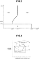
- the hybrid vehicle has three drive modes according to the accelerator opening APO and the vehicle speed VSP. That is, the hybrid vehicle has an electric vehicle drive mode (an EV drive mode) in which the first clutch CL1 is in a disengaged state and the vehicle travels by only power of the motor/generator MG as a power source, an engine-used drive mode (an HEV drive mode) in which the first clutch CL1 is in an engaged state and the vehicle travels while including the engine E as the power source, and an engine-used slip drive mode (a WSC drive mode) in which the first clutch CL1 is in the engaged state and the second clutch CL2 is slip-controlled, then the vehicle travels while including the engine E as the power source.
- an electric vehicle drive mode an EV drive mode
- an HEV drive mode in which the first clutch CL1 is in an engaged state and the vehicle travels while including the engine E as the power source
- a WSC drive mode engine-used slip drive mode
- the HEV drive mode includes three drive modes of an engine drive mode, a motor assist drive mode and a travelling power generation mode.
- the vehicle travels by only power of the engine E.
- the motor assist drive mode the vehicle travels by both powers of the engine E and the motor/generator MG.
- the travelling power generation mode the vehicle travels with the engine E being the power source and the motor/generator MG works as the generator.
- the motor/generator MG Upon deceleration, by receiving a regenerative brake energy, the motor/generator MG generates the power and charges the battery 4.
- the hybrid vehicle further has a power generation mode in which during vehicle stop, the motor/generator MG is operated as the generator by using power of the engine E.
- the mode is forcefully shifted from EV drive mode to the HEV drive mode.
- Fig. 3 is a drawing showing characteristics of the target air-fuel ratio for an operating condition (the torque and the engine rotation speed) of the engine E.
- the engine E In the above HEV drive mode, e.g. in the engine drive mode, the engine E is operated at an operating point (a specific combination of the torque and the engine rotation speed) determined so as to attain a target engine torque on the basis of the command that the engine controller 1 receives from the integrated controller 10.
- the lean combustion mode is selected. If the operating point is positioned in a stoichiometric combustion operating region illustrated as a "stoichiometric region" in Fig. 3 , the stoichiometric combustion mode is selected.
- the engine controller 1 has a combustion mode change map corresponding to the characteristics of Fig. 3 .
- the stoichiometric combustion operating region exists at both sides of a low torque side and a high torque side with respect to the lean combustion operating region, and a high rotation speed side with respect to a certain rotation speed is also the stoichiometric combustion operating region.
- a boundary at a high torque side between the lean combustion operating region and the stoichiometric combustion operating region is a first boundary L1 at which a change from the lean combustion mode to the stoichiometric combustion mode is executed when the torque of the engine E increases and a second boundary L2 at which a change from the stoichiometric combustion mode to the lean combustion mode is executed when the torque of the engine E decreases.
- the second boundary L2 is set at a low torque side as compared with the first boundary L1.
- the secondboundary L2 at the torque decrease has a hysteresis at the low torque side with respect to the first boundary L1 at the torque increase.
- the lean combustion operating region is substantially wide.
- the second boundary L2 is set along a performance limit of the motor/generator MG that performs the assist of the driving force at the mode change operation as described later.
- Figs. 4A to 4F show time charts of the combustion mode change operation upon shift of the region (in a scene 2) shown by the arrow S2 in Fig. 3 .
- This scene 2 corresponds to a situation, for instance, as shown in Fig. 4A , where from an operating state with such a relatively large accelerator opening that the vehicle speed increases, the accelerator opening is decreased stepwise at time t1 in order for the vehicle speed to be constant.
- the operating point changes as shown by the arrow S2 in Fig. 3 , and crosses the second boundary L2.
- Figs. 5A to 5F show time charts of the combustion mode change operation when the state of charge of the battery 4 is a predetermined level or lower (e.g. the SOC is a predetermined value or lower) upon shift of the region (in the scene 2) shown by the same arrow S2 in Fig. 3 .
- a predetermined level or lower e.g. the SOC is a predetermined value or lower
- the opening degree of the throttle valve is increased for this change, in the same manner as the above example, an actual intake-air quantity changes with the delay, and reaches the target intake-air quantity at time t2 (see Fig. 5B ).
- An occurrence of the intermediate exhaust air-fuel ratio is therefore suppressed.
- the driving force of the engine E is surplus to requirements between time t1 and time t2.
- the regenerative operation i.e. power absorption
- the motor/generator MG is performed so that a total of the driving force of the engine E and the driving force of the motor/generator MG conforms to a required driving force of the whole vehicle.
- Figs. 6A to 6g show time charts of the combustion mode change operation upon shift of the region (in a scene 1) shown by the arrow S1 in Fig. 3 .
- This scene 1 corresponds to a situation, for instance, as shown in Fig. 6A , where from an operating state with such a relatively small accelerator opening that the vehicle speed is held constant, the accelerator opening is increased stepwise at time t1 in order for the vehicle tobe accelerated.
- the operating point changes as shown by the arrow S1 in Fig. 3 , and crosses the first boundary L1.
- the second boundary L2 is set along the performance limit (i.e. a maximum output) of the motor/generator MG. Therefore, the second boundary L2 is positioned at a relatively low torque side.
- the second boundary L2 could be set at a slightly higher torque side than characteristics corresponding to the maximum output of the motor/generator MG.
- the first boundary L1 at which the combustion mode is changed from the lean combustion mode to the stoichiometric combustion mode, which does not require the assist of the motor/generator MG, is set at the higher torque side. That is, the lean combustion operating region which has the advantage of being good fuel efficiency is secured wide.
- Fig. 7 is a flow chart showing a flow of the control of the combustion mode change executed by the engine controller 1 and the motor controller 2.
- step S1 a judgment is made as to whether or not a current combustion mode is the lean combustion mode, in other words, whether or not an immediately preceding operating point of the engine E is in the lean combustion operating region.
- step S1 i.e. if the current combustion mode is the lean combustion mode, the routine proceeds to step S2, and a judgment is made as to whether or not the operating point is shifted to the stoichiometric combustion operating region. If NO at step S2, the lean combustion mode continues. If YES at step S2, i.e. if the operating point crosses the first boundary L1 from the lean combustion operating region and is shifted to the stoichiometric combustion operating region (see the arrow S1 in Fig. 3 ), the routine proceeds to step S3 from step S2, and the mode change operation from the lean combustion mode to the stoichiometric combustion mode, which is shown in Figs. 6A to 6G , is carried out.
- step S4 a judgment is made as to whether or not the intake-air quantity reaches the target intake-air quantity. If the intake-air quantity reaches the target intake-air quantity, the routine proceeds to step S5, and the control is shifted to a normal control by the stoichiometric combustion mode.
- step S6 i.e. if the current combustion mode is the stoichiometric combustion mode, the routine proceeds to step S6 from step S1, and a judgment is made as to whether or not the operating point is shifted to the lean combustion operating region. If NO at step S6, the stoichiometric combustion mode continues. If YES at step S6, i.e. if the operating point crosses the second boundary L2 from the stoichiometric combustion operating region and is shifted to the lean combustion operating region (see the arrow S2 in Fig. 3 ), the routine proceeds to step S7 from step S6, and a judgment is made as to whether or not the SOC of the battery 4 is greater than the predetermined value.
- step S9 a judgment is made as to whether or not the intake-air quantity reaches the target intake-air quantity. If the intake-air quantity reaches the target intake-air quantity, the routine proceeds to step S10, and the control is shifted to a normal control by the lean combustion mode.
- step S10 the routine proceeds to step S10, and the control is shifted to the normal control by the lean combustion mode. That is, in this case, as described above, the actual combustion mode is changed to the lean combustion mode at a time when the intake-air quantity reaches the target intake-air quantity.
- the present invention is not limited to the embodiment described above, but includes a various modifications.
- the present invention is not limited to this, but can use proper lean air-fuel ratios.
- the mode change operation using the regenerative operation of the motor/generator MG which is shown in Figs. 5A to 5F , is carried out.
- the mode change operation like Figs. 5A to 5F could be carried out.
- the mode change from the stoichiometric combustion mode to the lean combustion mode might not be performed when the SOC of the battery 4 is low.
- the present invention can be applied to a so-called mild hybrid type hybrid vehicle that has no large-sizedmotor/generatorMG for running and performs the torque assist by the starter/generator SSG.
Landscapes
- Engineering & Computer Science (AREA)
- Chemical & Material Sciences (AREA)
- Combustion & Propulsion (AREA)
- Mechanical Engineering (AREA)
- Transportation (AREA)
- General Engineering & Computer Science (AREA)
- Automation & Control Theory (AREA)
- Signal Processing (AREA)
- Electric Propulsion And Braking For Vehicles (AREA)
- Hybrid Electric Vehicles (AREA)
- Electrical Control Of Air Or Fuel Supplied To Internal-Combustion Engine (AREA)
- Combined Controls Of Internal Combustion Engines (AREA)
Abstract
Description
- The present invention relates to a method and a device for controlling a hybrid vehicle having an internal combustion engine and a motor as driving sources, particularly a hybrid vehicle using an internal combustion engine that is capable of changing a combustion mode between a stoichiometric combustion mode in which a stoichiometric air-fuel ratio is set as a target air-fuel ratio and a lean combustion mode in which a lean air-fuel ratio is set as the target air-fuel ratio.
- There is known an internal combustion engine that is capable of changing a combustion mode between a stoichiometric combustion mode in which a stoichiometric air-fuel ratio is set as a target air-fuel ratio and a lean combustion mode in which a lean air-fuel ratio is set as the target air-fuel ratio for improving fuel efficiency. For such an internal combustion engine, in terms of improvement in the fuel efficiency, it is desirable that the lean combustion mode be set in a wider range of an engine operating condition (torque and engine rotation speed).
- On the other hand, from the viewpoint of purification of exhaust gas of the internal combustion engine which is treated using a catalytic device etc., it is not preferable that an intermediate exhaust air-fuel ratio occur at the change of the combustion mode between the both stoichiometric and lean combustion modes at which the target air-fuel ratio is changed. That is, it is preferable for the exhaust air-fuel ratio to change stepwise along each target air-fuel ratio at the change of the combustion mode between the stoichiometric combustion mode and the lean combustion mode.
- However, a quantity of an intake air required for the combustion is different between the stoichiometric combustion mode and the lean combustion mode. Therefore, for instance, a throttle valve opening is changed according to the change of the combustion mode. However, even if the throttle valve opening is changed stepwise, in actual fact, delay in a change of the quantity of the intake air that flows into a combustion chamber occurs. Because of this, an actual intake-air quantity deviates from a target intake-air quantity due to this response delay. As a consequence, the intermediate exhaust air-fuel ratio temporarily occurs.
- An object of the present invention is therefore to improve the fuel efficiency by securing a wider range of a lean combustion operating region where the lean combustion mode is set and to suppress the occurrence of the intermediate exhaust air-fuel ratio at the change of the combustion mode to a minimum.
- Here,
Patent Document 1 discloses a technique that suppresses a torque shock at the change of the combustion mode between the stoichiometric combustion mode and the lean combustion mode in the hybrid vehicle by previously setting an output ratio of a motor to be high. However, the technique of thePatent Document 1 cannot solve the above problem raised by the present application. - Patent Document 1 : Japanese Unexamined Patent Application Publication No.
JP2008-068802 - As a control of the hybrid vehicle according to the present invention, a stoichiometric combustion operating region where a stoichiometric combustion mode is set and a lean combustion operating region where a lean combustion mode is set are previously set with torque and rotation speed of an internal combustion engine being parameters. And, as a boundary at a high torque side between the both operating regions, a second boundary at which a change from the stoichiometric combustion mode to the lean combustion mode is executed when the torque decreases is set at a low torque side as compared with a first boundary at which a change from the lean combustion mode to the stoichiometric combustion mode is executed when the torque increases. Then, upon shift from the stoichiometric combustion operating region to the lean combustion operating region, after changing the combustion mode, for delay in change of an intake-air quantity which is associated with the combustion mode change, a quantity-decrease correction of a fuel injection quantity is performed so as to maintain the target air-fuel ratio, and also the assist by a motor is performed so as to attain a required driving force.
- That is, upon shift from the stoichiometric combustion operating region to the lean combustion operating region, although the target air-fuel ratio changes from a stoichiometric air-fuel ratio to a lean air-fuel ratio and the target air-fuel ratio increases by and according to the combustion mode change, the delay in change of an actual intake-air quantity occurs. For this delay in intake-air quantity change, the quantity-decrease correction of the fuel injection quantity is performed so as to maintain the target air-fuel ratio that is a predetermined lean air-fuel ratio. With this, an occurrence of the intermediate exhaust air-fuel ratio is suppressed. Although the torque of the internal combustion engine is decreased by this quantity-decrease correction of the fuel injection quantity, by performing assist by a power running operation of the motor, it is possible to attain a required driving force of the whole vehicle.
- Since the shift from the stoichiometric combustion mode to the lean combustion mode involves the assist by the motor in this manner, by setting the second boundary at which this shift should be performed at the low torque side, the shift while excluding the intermediate exhaust air-fuel ratio can be possible without requiring an excessively large torque. In contrast to this, regarding a shift from the lean combustion mode to the stoichiometric combustion mode, since a mode change that can attain the required driving force is possible, for instance, by performing ignition timing retard without depending on the motor, the shift can be set at a higher torque side without being limited by the second boundary. Therefore, the lean combustion mode can be set in a wider region, thereby improving the fuel efficiency of the internal combustion engine.
-
- [
Fig. 1] Fig. 1 is an explanatory drawing showing a system of a hybrid vehicle according to the present invention. - [
Fig. 2] Fig. 2 is characteristics showing a plurality of drive modes of the hybrid vehicle. - [
Fig. 3] Fig. 3 is a drawing showing characteristics of a target air-fuel ratio of an engine. - [
Fig. 4] Figs. 4A to 4F are time charts showing a mode change operation in a scene 2 (an arrow S2). - [
Fig. 5] Figs. 5A to 5F are time charts showing a mode change operation in thescene 2 when a battery SOC is low. - [
Fig. 6] Figs. 6A to 6G are time charts showing a mode change operation in a scene 1 (an arrow S1). - [
Fig. 7] Fig. 7 is a flow chart showing a flow of the mode change operation in an embodiment. -
Fig. 1 is an explanatory drawing showing a system of a hybrid vehicle according to the present invention. The hybrid vehicle has an engine E that is an internal combustion engine and a motor/generator MG, and drives rear-right and rear-left wheels (driving wheels) RR and RL through a first clutch CL1, a second clutch CL2, an automatic transmission AT, a differential mechanism DF etc.. - The engine E is, for instance, a direct-inj ection spark-ignition gasoline engine, and a throttle valve opening, a fuel injection quantity and an ignition timing (all not shown) etc. are controlled on the basis of a control command from an
engine controller 1. This engine E is particularly configured to be able to change a combustion mode between a stoichiometric combustion mode in which a stoichiometric air-fuel ratio (i.e. an excess coefficient (or an excess air ratio) λ = 1) is set as a target air-fuel ratio and a lean combustion mode in which a lean air-fuel ratio (e.g. λ = 2) is set as the target air-fuel ratio. Further, the engine E is provided with an exhaust gas purifying device using a catalyst in an exhaust system (all not shown). For instance, by making a switch of a flow passage according to each combustion mode, proper exhaust purification is realized under each combustion mode (in other words, under each exhaust air-fuel ratio). - The engine E is also provided with a starter/generator SSG that is connected to a crankshaft of the engine E through a belt drive mechanism. This starter/generator SSG is controlled to perform either one of a power running operation or a regenerative operation by an SSG controller SSGCU. Upon the power running operation, the starter/generator SSG works as the starter for an engine start. Upon the regenerative operation, the starter/generator SSG generates electric power as the generator.
- The first clutch CL1 is a normally-engaged dry clutch that is interposed between the engine E and the motor/generator MG. Engagement and disengagement of the first clutch CL1 are controlled by a control pressure that is produced by a first clutch
hydraulic unit 6 on the basis of a control command from afirst clutch controller 5. Further, slip-engagement by which torque is transmitted while the first clutch CL1 slips is possible by the above control pressure. - The motor/generator MG is a permanent magnet type three-phase AC electric motor. The motor/generator MG is controlled to perform either one of a power running operation or a regenerative operation through an
inverter 3 on the basis of a control command from amotor controller 2. By performing the power running operation by receiving power from abattery 4, the motor/generator MG can assist vehicle drive by providing a vehicle driving force . Also, by performing the regenerative operation, the motor/generator MG charges thebattery 4. A rotor of the motor/generator MG, using a permanent magnet, is connected to an input shaft of the automatic transmission AT through a damper (not shown). - The second clutch CL2 is a clutch that is positioned between the motor/generator MG and the rear-right and rear-left wheels RR and RL and works also as a starting clutch. The second clutch CL2 is actually configured by one or a plurality of frictional engagement elements such as a clutch and a brake provided in the automatic transmission AT. Engagement and disengagement including slip-engagement of the second clutch CL2 are controlled by a control pressure that is produced by an AT hydraulic
pressure control unit 8 on the basis of a control command from anAT controller 7. - The automatic transmission AT is, for instance, a multi-range transmission (or a multi-speed transmission). A speed shift control of the automatic transmission AT is performed on the basis of a vehicle speed VSP and an accelerator opening (an accelerator pedal operating amount by a driver) APO etc. by the
AT controller 7. - The hybrid vehicle has, as a control system, the
engine controller 1, themotor controller 2, theinverter 3, thebattery 4, thefirst clutch controller 5, the first clutchhydraulic unit 6, theAT controller 7, the AT hydraulicpressure control unit 8, abrake controller 9, anintegrated controller 10 and the SSG controller SSGCU. Theengine controller 1, themotor controller 2, thefirst clutch controller 5, theAT controller 7, thebrake controller 9, theintegrated controller 10 and the SSG controller SSGCU are connected with each other through aCAN communication line 11 that allows exchange of information between them. - The
engine controller 1 controls the throttle valve opening and the fuel injection quantity etc. on the basis of a target engine torque command from the integratedcontroller 10 which is based on a required driving force. Theengine controller 1 inputs engine rotation speed information from an enginerotation speed sensor 12, a cylinder discrimination signal from acylinder discrimination sensor 32, intake-air quantity information from an intake-air quantity sensor 33 and so on. - The
motor controller 2 inputs information from aresolver 13 that detects a rotation position of the rotor of the motor/generator MG, a target motor torque command from the integratedcontroller 10 and so on. Themotor controller 2 outputs a command that controls a motor operating point of the motor/generator MG in accordance with the target motor torque command etc. to theinverter 3. Further, themotor controller 2 checks or watches an SOC (State Of Charge) indicating a charge state of thebattery 4. SOC information is used for control of the motor/generator MG, and also is sent to theintegrated controller 10. - The first
clutch controller 5 inputs sensor information from a first clutchhydraulic pressure sensor 14 and a firstclutch stroke sensor 15, and also inputs a first clutch control command from the integratedcontroller 10. The firstclutch controller 5 then outputs an engagement/disengagement control command for the first clutch CL1 to the first clutchhydraulic unit 6 on the basis of these inputted information and command.
Information of a first clutch stroke C1S by the firstclutch stroke sensor 15 is sent to theintegrated controller 10. - The
AT controller 7 inputs sensor signals from sensors such as an acceleratorpedal opening sensor 16, a vehicle speed sensor 17, a second clutchhydraulic pressure sensor 18 and aninhibitor switch 28 that outputs a range signal corresponding to a shift position of a selectinglever 27, and also inputs a control command from the integratedcontroller 10. TheAT controller 7 then outputs a control command to the AT hydraulicpressure control unit 8 on the basis of these inputted signals and command. The accelerator opening APO, the vehicle speed VSP and the inhibitor switch signal are sent to theintegrated controller 10. - The
brake controller 9 inputs sensor information from awheel speed sensor 19 for detecting each wheel speed of four wheels and abrake stroke sensor 20. Thebrake controller 9 performs a regenerative brake cooperative control on the basis of a regenerative cooperative control command from the integratedcontroller 10 so as to compensate for the shortage of a regenerative braking force for a required braking force determined by a brake stroke BS with a mechanical braking force (a braking force by a friction brake) upon a brake operation by driver's brake pedal depression. - The
integrated controller 10 controls a consumption energy of the whole vehicle, and performs an integrated control of the engine E and the motor/generator MG etc. in order for the hybrid vehicle to travel at a high efficiency. Theintegrated controller 10 inputs information from a motorrotation speed sensor 21 that detects a motor rotation speed Nm, a second clutch outputrotation speed sensor 22 that detects a second clutch output rotation speed N2out, a secondclutch torque sensor 23 that detects a second clutch transmission torque capacity TCL2, a brakehydraulic pressure sensor 24 that detects a brake hydraulic pressure, a secondclutch temperature sensor 25 that detects temperature of the second clutch CL2, aG sensor 26 that detects a back-and-forth acceleration of the vehicle, a firstclutch temperature sensor 30 and aninverter temperature sensor 31, and also inputs information obtained from other controllers etc. via theCAN communication line 11. - Here, the
engine controller 1 and themotor controller 2 which are functionally integrated through theintegrated controller 10 correspond to a "controller" recited in claim. - As shown in
Fig. 2 , the hybrid vehicle has three drive modes according to the accelerator opening APO and the vehicle speed VSP. That is, the hybrid vehicle has an electric vehicle drive mode (an EV drive mode) in which the first clutch CL1 is in a disengaged state and the vehicle travels by only power of the motor/generator MG as a power source, an engine-used drive mode (an HEV drive mode) in which the first clutch CL1 is in an engaged state and the vehicle travels while including the engine E as the power source, and an engine-used slip drive mode (a WSC drive mode) in which the first clutch CL1 is in the engaged state and the second clutch CL2 is slip-controlled, then the vehicle travels while including the engine E as the power source. - Further, the HEV drive mode includes three drive modes of an engine drive mode, a motor assist drive mode and a travelling power generation mode. In the engine drive mode, the vehicle travels by only power of the engine E. In the motor assist drive mode, the vehicle travels by both powers of the engine E and the motor/generator MG. In the travelling power generation mode, the vehicle travels with the engine E being the power source and the motor/generator MG works as the generator. Upon deceleration, by receiving a regenerative brake energy, the motor/generator MG generates the power and charges the
battery 4. - The hybrid vehicle further has a power generation mode in which during vehicle stop, the motor/generator MG is operated as the generator by using power of the engine E. Here, in a case where the SOC of the
battery 4 is low and/or there is an idle stop forbidden demand, the mode is forcefully shifted from EV drive mode to the HEV drive mode. -
Fig. 3 is a drawing showing characteristics of the target air-fuel ratio for an operating condition (the torque and the engine rotation speed) of the engine E. In the above HEV drive mode, e.g. in the engine drive mode, the engine E is operated at an operating point (a specific combination of the torque and the engine rotation speed) determined so as to attain a target engine torque on the basis of the command that theengine controller 1 receives from the integratedcontroller 10. As described above, the engine E is configured to be able to change the combustion mode between the stoichiometric combustion mode in which the stoichiometric air-fuel ratio (λ = 1) is set as the target air-fuel ratio and the lean combustion mode in which the lean air-fuel ratio (λ = 2) is set as the target air-fuel ratio. If the operating point is positioned in a lean combustion operating region illustrated as a "lean region" inFig. 3 , the lean combustion mode is selected. If the operating point is positioned in a stoichiometric combustion operating region illustrated as a "stoichiometric region" inFig. 3 , the stoichiometric combustion mode is selected. For instance, theengine controller 1 has a combustion mode change map corresponding to the characteristics ofFig. 3 . The stoichiometric combustion operating region exists at both sides of a low torque side and a high torque side with respect to the lean combustion operating region, and a high rotation speed side with respect to a certain rotation speed is also the stoichiometric combustion operating region. - Here, as a boundary at a high torque side between the lean combustion operating region and the stoichiometric combustion operating region, it is a first boundary L1 at which a change from the lean combustion mode to the stoichiometric combustion mode is executed when the torque of the engine E increases and a second boundary L2 at which a change from the stoichiometric combustion mode to the lean combustion mode is executed when the torque of the engine E decreases. The second boundary L2 is set at a low torque side as compared with the first boundary L1. Inotherwords, the secondboundary L2 at the torque decrease has a hysteresis at the low torque side with respect to the first boundary L1 at the torque increase.
- Therefore, in a case where the torque increases during the engine operation in the lean combustion mode in the lean combustion operating region, when the operating point crosses the first boundary L1, a mode change operation to the stoichiometric combustion mode is executed (see an arrow S1 in
Fig. 3 ). Conversely, in a case where the torque decreases during the engine operation in the stoichiometric combustion mode in the stoichiometric combustion operating region at the high torque side, even if the operating point is shifted to a low torque side with respect to the first boundary L1, the stoichiometric combustion mode continues, but when the operating point crosses the second boundary L2, a mode change operation to the lean combustion mode is executed (see an arrow S2 inFig. 3 ). Then, once the combustion mode is changed to the lean combustion mode by the operating point crossing the second boundary L2, even if the torque increases, the lean combustion mode is maintained until the operating point crosses the first boundary L1. - In other words, as compared with the lean combustion operating region determined by the second boundary L2 for a torque decrease direction, regarding a torque increase direction, since the first boundary L1 is set at the high torque side, the lean combustion operating region is substantially wide.
- Here, the first boundary L1 is set along a limit of a torque by which when increasing the fuel injection quantity according to the torque increase, a lean combustion with the target air-fuel ratio set to the lean air-fuel ratio (e.g. λ = 2) can be established (along a torque by which when increasing the fuel injection quantity according to the torque increase, a limit of establishment of a lean combustion with the target air-fuel ratio set to the lean air-fuel ratio (e.g. λ = 2) is determined) . The second boundary L2 is set along a performance limit of the motor/generator MG that performs the assist of the driving force at the mode change operation as described later.
-
Figs. 4A to 4F show time charts of the combustion mode change operation upon shift of the region (in a scene 2) shown by the arrow S2 inFig. 3 . Thisscene 2 corresponds to a situation, for instance, as shown inFig. 4A , where from an operating state with such a relatively large accelerator opening that the vehicle speed increases, the accelerator opening is decreased stepwise at time t1 in order for the vehicle speed to be constant. At time t1, the operating point changes as shown by the arrow S2 inFig. 3 , and crosses the second boundary L2. - By and according to this shift of the operating point, as shown in
Fig. 4C , the combustion mode is changed from the stoichiometric combustion mode (λ = 1) to the lean combustion mode (λ = 2), and the target air-fuel ratio becomes an air-fuel ratio corresponding to "λ = 2". Since a required intake-air quantity (a required quantity of fresh air) is increased by this change of the target air-fuel ratio, a target intake-air quantity changes stepwise, and the opening (an opening degree) of the throttle valve is promptly increased. However, as shown inFig. 4B , in actual fact, delay in a change of the quantity of the intake air that flows into the cylinder occurs. For instance, the intake-air quantity reaches the target intake-air quantity corresponding to "λ = 2" at time t2. Therefore, an actual intake-air quantity is insufficient for the target intake-air quantity corresponding to "λ = 2" between time t1 and time t2. - In response to such shortage of the intake-air quantity, as shown in
Fig. 4D , a quantity-decrease correction of the fuel injection quantity is carried out. More specifically, for the delay in the change of the intake-air quantity as shown inFig. 4B , the fuel injection quantity is decreased so as to maintain the target air-fuel ratio (λ = 2). With this correction, the exhaust air-fuel ratio of the exhaust that undergoes purification by a catalytic device is changed stepwise from an exhaust air-fuel ratio corresponding to "λ = 1" to an exhaust air-fuel ratio corresponding to "λ = 2" at time t1, then an occurrence of an intermediate exhaust air-fuel ratio is suppressed. Here, strictly speaking, although the fuel injection quantity required for the same torque is slightly different between the stoichiometric combustion mode and the lean combustion mode, from the viewpoint of the purification of the exhaust, the quantity-decrease correction is carried out so that the exhaust air-fuel ratio becomes a constant value corresponding to "λ = 2". Since the intake-air quantity gradually approaches the target intake-air quantity from time t1 toward time t2, the quantity-decrease correction of the fuel injection quantity is gradually reduced or lessened. - As a result of the above quantity-decrease correction of the fuel injection quantity, as shown in
Fig. 4E , torque that the engine E actually produces is smaller than the target engine torque. For this torque reduction, as shown inFig. 4F , the assist by the motor/generator MG is performed on the basis of the command provided to themotor controller 2 from the integratedcontroller 10 so that a total of the driving force of the engine E and the driving force of the motor/generator MG becomes (meets or attains) a required driving force of the whole vehicle. Hence, the operation along the required driving force becomes possible while avoiding the exhaust air-fuel ratio being an intermediate value at the mode change. - Next,
Figs. 5A to 5F show time charts of the combustion mode change operation when the state of charge of thebattery 4 is a predetermined level or lower (e.g. the SOC is a predetermined value or lower) upon shift of the region (in the scene 2) shown by the same arrow S2 inFig. 3 . - In this case, at time t1, the target intake-air quantity is changed so as to correspond to the lean air-fuel ratio (λ = 2) in advance of an actual combustion mode change . Although the opening degree of the throttle valve is increased for this change, in the same manner as the above example, an actual intake-air quantity changes with the delay, and reaches the target intake-air quantity at time t2 (see
Fig. 5B ). - As shown in
Fig. 5C , the actual combustion mode change is not carried out at time t1, but carried out from the stoichiometric combustion mode to the lean combustion mode when the intake-air quantity reaches the target intake-air quantity at time t2. Therefore, the actual intake-air quantity is surplus to the intake-air quantity corresponding to "λ = 1" between time t1 and time t2. - In response to such surplus of the intake-air quantity, in this example, as shown in
Fig. 5D , a quantity-increase correction of the fuel injection quantity is carried out between time t1 and time t2 so as to maintain the stoichiometric air-fuel ratio (λ = 1) as it stands as the target air-fuel ratio. Since the intake-air quantity gradually approaches the target intake-air quantity, a quantity-increase correction amount is gradually reduced. Then, when the intake-air quantity reaches the target intake-air quantity at time t2, the quantity-increase correction is ended, and the fuel injection quantity corresponding to the lean air-fuel ratio (λ = 2) is set. - Consequently, the exhaust air-fuel ratio is maintained at an exhaust air-fuel ratio corresponding to "λ = 1" between time t1 and time t2, and changes stepwise to an exhaust air-fuel ratio corresponding to "λ = 2" at time t2. An occurrence of the intermediate exhaust air-fuel ratio is therefore suppressed.
- On the other hand, as shown in
Fig. 5E , by and according to the above quantity-increase correction, the driving force of the engine E is surplus to requirements between time t1 and time t2. For this surplus driving force of the engine E, as shown inFig. 5F , the regenerative operation (i.e. power absorption) by the motor/generator MG is performed so that a total of the driving force of the engine E and the driving force of the motor/generator MG conforms to a required driving force of the whole vehicle. - Next,
Figs. 6A to 6g show time charts of the combustion mode change operation upon shift of the region (in a scene 1) shown by the arrow S1 inFig. 3 . Thisscene 1 corresponds to a situation, for instance, as shown inFig. 6A , where from an operating state with such a relatively small accelerator opening that the vehicle speed is held constant, the accelerator opening is increased stepwise at time t1 in order for the vehicle tobe accelerated. At time t1, the operating point changes as shown by the arrow S1 inFig. 3 , and crosses the first boundary L1. - By and according to this shift of the operating point, as shown in
Fig. 6C , the combustion mode is changed from the lean combustion mode (λ = 2) to the stoichiometric combustion mode (λ = 1), and the target air-fuel ratio becomes an air-fuel ratio corresponding to "λ = 1". Since a required intake-air quantity (a required quantity of fresh air) is decreased by this change of the target air-fuel ratio, a target intake-air quantity changes stepwise, and the opening degree of the throttle valve is promptly decreased. However, as shown inFig. 6B , in actual fact, delay in a change of the quantity of the intake air that flows into the cylinder occurs. For instance, the intake-air quantity reaches the target intake-air quantity corresponding to "λ = 1" at time t2. Therefore, an actual intake-air quantity is surplus to the target intake-air quantity corresponding to "λ = 1" between time t1 and time t2. - In response to such surplus of the intake-air quantity, as shown in
Fig. 6D , a quantity-increase correction of the fuel injection quantity is carried out. More specifically, for the delay in the change of the intake-air quantity as shown inFig. 6B , the fuel injection quantity is increased so as to maintain the target air-fuel ratio (λ= 1). With this correction, the exhaust air-fuel ratio of the exhaust that undergoes purification by the catalytic device is changed stepwise from an exhaust air-fuel ratio corresponding to "λ = 2" to an exhaust air-fuel ratio corresponding to "λ = 1" at time t1, then an occurrence of the intermediate exhaust air-fuel ratio is suppressed. Here, strictly speaking, although the fuel injection quantity required for the same torque is slightly different between the lean combustion mode and the stoichiometric combustion mode, from the viewpoint of the purification of the exhaust, the quantity-increase correction is carried out so that the exhaust air-fuel ratio becomes a constant value corresponding to "λ = 1". Since the intake-air quantity gradually approaches the target intake-air quantity from time t1 toward time t2, the quantity-increase correction of the fuel injection quantity is gradually reduced or lessened. - As a result of the above quantity-increase correction of the fuel injection quantity, as shown by a broken line in
Fig. 6E , torque that the engine E produces could temporally become greater than the target engine torque. For this temporal torque increase, as shown inFig. 6G , in order to suppress the torque, an ignition timing is retarded. That is, the ignition timing is corrected to a retarded side with respect to an MBT point. With this ignition timing retard, as shown by a solid line inFig. 6E , torque that the engine E actually produces conforms to the target engine torque. Hence, the operation along the required driving force becomes possible while avoiding the exhaust air-fuel ratio being an intermediate value at the mode change. - As described above, since the mode change from the stoichiometric combustion mode to the lean combustion mode at the second boundary L2 like the
scene 2 involves the assist (or the regenerative operation) by the motor/generator MG, the second boundary L2 is set along the performance limit (i.e. a maximum output) of the motor/generator MG. Therefore, the second boundary L2 is positioned at a relatively low torque side. Here, if some torque step at the combustion mode change is acceptable, the second boundary L2 could be set at a slightly higher torque side than characteristics corresponding to the maximum output of the motor/generator MG. - As compared with the setting of the second boundary L2, the first boundary L1 at which the combustion mode is changed from the lean combustion mode to the stoichiometric combustion mode, which does not require the assist of the motor/generator MG, is set at the higher torque side. That is, the lean combustion operating region which has the advantage of being good fuel efficiency is secured wide.
-
Fig. 7 is a flow chart showing a flow of the control of the combustion mode change executed by theengine controller 1 and themotor controller 2. At step S1, a judgment is made as to whether or not a current combustion mode is the lean combustion mode, in other words, whether or not an immediately preceding operating point of the engine E is in the lean combustion operating region. - If YES at step S1, i.e. if the current combustion mode is the lean combustion mode, the routine proceeds to step S2, and a judgment is made as to whether or not the operating point is shifted to the stoichiometric combustion operating region. If NO at step S2, the lean combustion mode continues. If YES at step S2, i.e. if the operating point crosses the first boundary L1 from the lean combustion operating region and is shifted to the stoichiometric combustion operating region (see the arrow S1 in
Fig. 3 ), the routine proceeds to step S3 from step S2, and the mode change operation from the lean combustion mode to the stoichiometric combustion mode, which is shown inFigs. 6A to 6G , is carried out. That is, as described above, the combustion mode is immediately changed to the stoichiometric combustion mode, and by performing the quantity-increase correction of the fuel injection quantity and the ignition timing retard, the exhaust air-fuel ratio is changed stepwise to the exhaust air-fuel ratio corresponding to "λ = 1". - At step S4, a judgment is made as to whether or not the intake-air quantity reaches the target intake-air quantity. If the intake-air quantity reaches the target intake-air quantity, the routine proceeds to step S5, and the control is shifted to a normal control by the stoichiometric combustion mode.
- If NO at step S1, i.e. if the current combustion mode is the stoichiometric combustion mode, the routine proceeds to step S6 from step S1, and a judgment is made as to whether or not the operating point is shifted to the lean combustion operating region. If NO at step S6, the stoichiometric combustion mode continues. If YES at step S6, i.e. if the operating point crosses the second boundary L2 from the stoichiometric combustion operating region and is shifted to the lean combustion operating region (see the arrow S2 in
Fig. 3 ), the routine proceeds to step S7 from step S6, and a judgment is made as to whether or not the SOC of thebattery 4 is greater than the predetermined value. If the SOC of thebattery 4 is greater than the predetermined value, the routine proceeds to step S8 from step S7, and the mode change operation from the stoichiometric combustion mode to the lean combustion mode, which is shown inFigs. 4A to 4F , is carried out. That is, as described above, the combustion mode is immediately changed to the lean combustion mode, and by performing the quantity-decrease correction of the fuel injection quantity and the torque assist by the power running operation of the motor/generator MG, the exhaust air-fuel ratio is changed stepwise to the exhaust air-fuel ratio corresponding to "λ = 2". - At step S9, a judgment is made as to whether or not the intake-air quantity reaches the target intake-air quantity. If the intake-air quantity reaches the target intake-air quantity, the routine proceeds to step S10, and the control is shifted to a normal control by the lean combustion mode.
- If the SOC of the
battery 4 is equal to or less then the predetermined value at step S7, the routine proceeds to step S11 from step S7, and the mode change operation from the stoichiometric combustion mode to the lean combustion mode, which is shown inFigs. 5A to 5F , is carried out. That is, as described above, the target intake-air quantity is immediately changed, and by performing the quantity-increase correction of the fuel injection quantity and the torque absorption by the regenerative operation of the motor/generator MG, the stoichiometric combustion mode corresponding to "λ = 1" continues. Then, at step S12, a judgment is made as to whether or not the intake-air quantity reaches the target intake-air quantity. If the intake-air quantity reaches the target intake-air quantity, the routine proceeds to step S10, and the control is shifted to the normal control by the lean combustion mode. That is, in this case, as described above, the actual combustion mode is changed to the lean combustion mode at a time when the intake-air quantity reaches the target intake-air quantity. - Although one embodiment of the present invention has been explained in detail, the present invention is not limited to the embodiment described above, but includes a various modifications. For instance, the above embodiment shows the example in which the air-fuel ratio of the lean combustion mode is an air-fuel ratio corresponding to "λ = 2". However, the present invention is not limited to this, but can use proper lean air-fuel ratios. Further, in the above embodiment, when the SOC of the
battery 4 is low, the mode change operation using the regenerative operation of the motor/generator MG, which is shown inFigs. 5A to 5F , is carried out. However, besides the condition of the SOC of thebattery 4, in a case where the torque assist by the motor/generator MG is difficult, the mode change operation likeFigs. 5A to 5F could be carried out. In addition, the mode change from the stoichiometric combustion mode to the lean combustion mode might not be performed when the SOC of thebattery 4 is low. - Further, the present invention can be applied to a so-called mild hybrid type hybrid vehicle that has no large-sizedmotor/generatorMG for running and performs the torque assist by the starter/generator SSG.
Claims (6)
- A method for controlling a hybrid vehicle, the hybrid vehicle having an internal combustion engine that is capable of changing a combustion mode between a stoichiometric combustion mode in which a stoichiometric air-fuel ratio is set as a target air-fuel ratio and a lean combustion mode in which a lean air-fuel ratio is set as the target air-fuel ratio and a motor that is capable of performing assist of power of the internal combustion engine by a power running operation, the method comprising:previously setting a stoichiometric combustion operating region where the stoichiometric combustion mode is set and a lean combustion operating region where the lean combustion mode is set with torque and rotation speed of the internal combustion engine being parameters;as a boundary at a high torque side between the both operating regions, setting a second boundary at which a change from the stoichiometric combustion mode to the lean combustion mode is executed when the torque decreases at a low torque side as compared with a first boundary at which a change from the lean combustion mode to the stoichiometric combustion mode is executed when the torque increases; andupon shift from the stoichiometric combustion operating region to the lean combustion operating region, after changing the combustion mode, for delay in change of an intake-air quantity which is associated with the combustion mode change, performing a quantity-decrease correction of a fuel injection quantity so as to maintain the target air-fuel ratio, and performing the assist by the motor so as to attain a required driving force.
- The method for controlling the hybrid vehicle as claimed in claim 1, wherein:
the second boundary is set in relation to a maximum output of the motor. - The method for controlling the hybrid vehicle as claimed in claim 1 or 2, wherein:as the motor, a motor that is capable of performing the assist of the power of the internal combustion engine by the power running operation and also performing absorption of the power of the internal combustion engine by a regenerative operation is used, andthe method further comprising:
upon shift from the stoichiometric combustion operating region to the lean combustion operating region, under specific conditions, after changing a target intake-air quantity so as to correspond to the lean air-fuel ratio in advance of the combustion mode change, performing a quantity-increase correction of the fuel injection quantity so as to maintain the stoichiometric air-fuel ratio as the target air-fuel ratio for a time period of the delay of the intake-air quantity change, and performing the regenerative operation of the motor so as to attain the required driving force. - The method for controlling the hybrid vehicle as claimed in claim 3, wherein:
one of the specific conditions is that a state of charge of a battery that is a power source for the motor is a predetermined level or lower. - The method for controlling the hybrid vehicle as claimed in any one of the preceding claims 1 to 4, further comprising:
upon shift from the lean combustion operating region to the stoichiometric combustion operating region, after changing the combustion mode, for delay in change of the intake-air quantity which is associated with the combustion mode change, performing a quantity-increase correction of the fuel injection quantity so as to maintain the target air-fuel ratio, and suppressing the torque by performing ignition timing retard. - A control device of a hybrid vehicle comprising:an internal combustion engine that is capable of changing a combustion mode between a stoichiometric combustion mode in which a stoichiometric air-fuel ratio is set as a target air-fuel ratio and a lean combustion mode in which a lean air-fuel ratio is set as the target air-fuel ratio;a motor that is capable of performing assist of power of the internal combustion engine by a power running operation; anda controller that controls the internal combustion engine and the motor, and whereinthe controller has a combustion mode change map in which a stoichiometric combustion operating region where the stoichiometric combustion mode is set and a lean combustion operating region where the lean combustion mode is set are previously set with torque and rotation speed of the internal combustion engine being parameters,a boundary at a high torque side between the both operating regions in the combustion mode change map has a first boundary at which a change from the lean combustion mode to the stoichiometric combustion mode is executed when the torque increases and a second boundary which is set at a low torque side with respect to the first boundary and at which a change from the stoichiometric combustion mode to the lean combustion mode is executed when the torque decreases, andthe controller is configured to, upon shift from the stoichiometric combustion operating region to the lean combustion operating region, after changing the combustion mode, for delay in change of an intake-air quantity which is associated with the combustion mode change, perform a quantity-decrease correction of a fuel injection quantity so as to maintain the target air-fuel ratio, and perform the assist by the motor so as to attain a required driving force.
Applications Claiming Priority (1)
| Application Number | Priority Date | Filing Date | Title |
|---|---|---|---|
| PCT/JP2017/036901 WO2019073561A1 (en) | 2017-10-12 | 2017-10-12 | Method and device for controlling hybrid vehicle |
Publications (3)
| Publication Number | Publication Date |
|---|---|
| EP3696036A1 true EP3696036A1 (en) | 2020-08-19 |
| EP3696036A4 EP3696036A4 (en) | 2020-11-11 |
| EP3696036B1 EP3696036B1 (en) | 2021-08-18 |
Family
ID=66100541
Family Applications (1)
| Application Number | Title | Priority Date | Filing Date |
|---|---|---|---|
| EP17928635.6A Active EP3696036B1 (en) | 2017-10-12 | 2017-10-12 | Method and device for controlling hybrid vehicle |
Country Status (5)
| Country | Link |
|---|---|
| US (1) | US11208094B2 (en) |
| EP (1) | EP3696036B1 (en) |
| JP (1) | JP6852802B2 (en) |
| CN (1) | CN111278700B (en) |
| WO (1) | WO2019073561A1 (en) |
Families Citing this family (12)
| Publication number | Priority date | Publication date | Assignee | Title |
|---|---|---|---|---|
| US11441497B2 (en) * | 2018-01-23 | 2022-09-13 | Nissan Motor Co., Ltd. | Internal combustion engine control method and internal combustion engine control device |
| GB2593761B (en) * | 2020-04-02 | 2022-09-28 | Jaguar Land Rover Ltd | Lean operating hybrid gasoline engine |
| JP7277491B2 (en) * | 2021-02-04 | 2023-05-19 | 本田技研工業株式会社 | control unit and vehicle |
| JP7460028B2 (en) * | 2021-07-26 | 2024-04-02 | 日産自動車株式会社 | Vehicle control method and vehicle control device |
| WO2023007531A1 (en) * | 2021-07-26 | 2023-02-02 | 日産自動車株式会社 | Vehicle control method and vehicle control device |
| CN117751064A (en) * | 2021-08-04 | 2024-03-22 | 日产自动车株式会社 | Control method for hybrid vehicle and control device for hybrid vehicle |
| CN113859214B (en) * | 2021-09-28 | 2023-03-14 | 清华大学 | Hybrid system engine dynamic energy efficiency control method and device |
| JP7605147B2 (en) * | 2022-02-09 | 2024-12-24 | トヨタ自動車株式会社 | Exhaust gas purification device for internal combustion engines |
| DE102022125438A1 (en) * | 2022-09-30 | 2024-04-04 | HTM Hydro Technology Motors GmbH | Method for operating a hybrid drive train of a motor vehicle and hybrid drive train |
| JP7487808B1 (en) | 2023-02-21 | 2024-05-21 | いすゞ自動車株式会社 | vehicle |
| JP7533649B1 (en) | 2023-02-22 | 2024-08-14 | いすゞ自動車株式会社 | Drive system |
| JP7485124B1 (en) | 2023-02-24 | 2024-05-16 | いすゞ自動車株式会社 | CONTROL DEVICE, VEHICLE, AND CONTROL METHOD |
Family Cites Families (21)
| Publication number | Priority date | Publication date | Assignee | Title |
|---|---|---|---|---|
| JP3534271B2 (en) * | 1995-04-20 | 2004-06-07 | 株式会社エクォス・リサーチ | Hybrid vehicle |
| JPH11107815A (en) * | 1997-10-08 | 1999-04-20 | Toyota Motor Corp | Combustion control device for lean burn internal combustion engine |
| US6367570B1 (en) * | 1997-10-17 | 2002-04-09 | Electromotive Inc. | Hybrid electric vehicle with electric motor providing strategic power assist to load balance internal combustion engine |
| KR20030011347A (en) * | 1998-04-28 | 2003-02-07 | 가부시키가이샤 히타치세이사쿠쇼 | Hybrid car and method for driving hybrid car |
| JP3699592B2 (en) * | 1998-06-19 | 2005-09-28 | 本田技研工業株式会社 | Control device for hybrid drive vehicle |
| US6428444B1 (en) * | 1999-09-06 | 2002-08-06 | Toyota Jidosha Kabushiki Kaisha | Apparatus for controlling a vehicle and a method of controlling the vehicle |
| JP3794218B2 (en) * | 1999-09-10 | 2006-07-05 | トヨタ自動車株式会社 | Control device for internal combustion engine |
| JP3607246B2 (en) * | 2001-11-30 | 2005-01-05 | 本田技研工業株式会社 | Control device for hybrid vehicle |
| JP3961277B2 (en) * | 2001-12-12 | 2007-08-22 | 本田技研工業株式会社 | Motor output control device for hybrid vehicle |
| JP2005069029A (en) | 2003-08-27 | 2005-03-17 | Toyota Motor Corp | Control device for internal combustion engine |
| JP2006009704A (en) * | 2004-06-25 | 2006-01-12 | Mazda Motor Corp | Fuel injection control device for in-cylinder internal combustion engine |
| JP3915809B2 (en) * | 2004-09-21 | 2007-05-16 | トヨタ自動車株式会社 | Hybrid vehicle that achieves lean limit with low power consumption |
| JP4197025B2 (en) | 2006-09-15 | 2008-12-17 | トヨタ自動車株式会社 | Hybrid vehicle |
| JP5359386B2 (en) * | 2009-03-05 | 2013-12-04 | 日産自動車株式会社 | Control device for hybrid vehicle |
| JP2014113954A (en) * | 2012-12-11 | 2014-06-26 | Toyota Motor Corp | Control unit of hybrid vehicle |
| DE112013007119B4 (en) * | 2013-05-31 | 2024-08-22 | Toyota Jidosha Kabushiki Kaisha | Control device for a hybrid vehicle |
| JP2015212128A (en) * | 2014-05-07 | 2015-11-26 | トヨタ自動車株式会社 | Control device for hybrid vehicle |
| JP5861745B2 (en) | 2014-06-30 | 2016-02-16 | トヨタ自動車株式会社 | Control device for internal combustion engine |
| JP2016017426A (en) * | 2014-07-07 | 2016-02-01 | トヨタ自動車株式会社 | Control device for internal combustion engine |
| JP6277994B2 (en) * | 2015-04-28 | 2018-02-14 | トヨタ自動車株式会社 | Control device for hybrid vehicle |
| JP6414128B2 (en) * | 2016-04-19 | 2018-10-31 | トヨタ自動車株式会社 | Internal combustion engine |
-
2017
- 2017-10-12 WO PCT/JP2017/036901 patent/WO2019073561A1/en not_active Ceased
- 2017-10-12 US US16/755,492 patent/US11208094B2/en not_active Expired - Fee Related
- 2017-10-12 CN CN201780095174.2A patent/CN111278700B/en not_active Expired - Fee Related
- 2017-10-12 EP EP17928635.6A patent/EP3696036B1/en active Active
- 2017-10-12 JP JP2019547849A patent/JP6852802B2/en not_active Expired - Fee Related
Also Published As
| Publication number | Publication date |
|---|---|
| CN111278700A (en) | 2020-06-12 |
| JPWO2019073561A1 (en) | 2021-01-21 |
| CN111278700B (en) | 2023-03-07 |
| EP3696036B1 (en) | 2021-08-18 |
| JP6852802B2 (en) | 2021-03-31 |
| EP3696036A4 (en) | 2020-11-11 |
| US11208094B2 (en) | 2021-12-28 |
| WO2019073561A1 (en) | 2019-04-18 |
| US20200398818A1 (en) | 2020-12-24 |
Similar Documents
| Publication | Publication Date | Title |
|---|---|---|
| EP3696036B1 (en) | Method and device for controlling hybrid vehicle | |
| JP3341659B2 (en) | Hybrid vehicle control device | |
| US8491441B2 (en) | Hybrid vehicle control device | |
| US8845481B2 (en) | Method and apparatus for executing a transmission shift in a powertrain system including a torque machine and an engine | |
| EP2532549B1 (en) | Engine start control device for hybrid vehicle | |
| US6026921A (en) | Hybrid vehicle employing parallel hybrid system, using both internal combustion engine and electric motor for propulsion | |
| JP5521340B2 (en) | Control device for hybrid vehicle | |
| EP2631466B1 (en) | Idling control device for vehicle | |
| JPH11178110A (en) | Hybrid vehicle control device | |
| US11207968B2 (en) | Hybrid vehicle cruise control device | |
| JP5359386B2 (en) | Control device for hybrid vehicle | |
| JP2014073693A (en) | Hybrid vehicle | |
| JP2018192824A (en) | Control device of hybrid vehicle | |
| JP2013187959A (en) | Vehicle | |
| US20190276003A1 (en) | Control device for hybrid vehicle | |
| JP5751192B2 (en) | Hybrid car | |
| JP6967406B2 (en) | Hybrid vehicle | |
| JP2012111450A (en) | Hybrid vehicle | |
| JP4086053B2 (en) | Control device for hybrid vehicle | |
| US20250229764A1 (en) | Hybrid electric vehicle | |
| JP5007621B2 (en) | Regenerative control device for hybrid vehicle | |
| JP2012244681A (en) | Electric vehicle | |
| JP2012035783A (en) | Hybrid vehicle | |
| JP2019025986A (en) | Hybrid vehicle | |
| JP2026001481A (en) | Hybrid vehicle control device |
Legal Events
| Date | Code | Title | Description |
|---|---|---|---|
| STAA | Information on the status of an ep patent application or granted ep patent |
Free format text: STATUS: THE INTERNATIONAL PUBLICATION HAS BEEN MADE |
|
| PUAI | Public reference made under article 153(3) epc to a published international application that has entered the european phase |
Free format text: ORIGINAL CODE: 0009012 |
|
| STAA | Information on the status of an ep patent application or granted ep patent |
Free format text: STATUS: REQUEST FOR EXAMINATION WAS MADE |
|
| 17P | Request for examination filed |
Effective date: 20200508 |
|
| AK | Designated contracting states |
Kind code of ref document: A1 Designated state(s): AL AT BE BG CH CY CZ DE DK EE ES FI FR GB GR HR HU IE IS IT LI LT LU LV MC MK MT NL NO PL PT RO RS SE SI SK SM TR |
|
| AX | Request for extension of the european patent |
Extension state: BA ME |
|
| A4 | Supplementary search report drawn up and despatched |
Effective date: 20201012 |
|
| RIC1 | Information provided on ipc code assigned before grant |
Ipc: B60K 6/48 20071001ALI20201006BHEP Ipc: B60K 6/387 20071001ALI20201006BHEP Ipc: B60W 20/15 20160101ALI20201006BHEP Ipc: F02D 41/04 20060101ALI20201006BHEP Ipc: F02D 41/02 20060101ALI20201006BHEP Ipc: F02D 45/00 20060101ALI20201006BHEP Ipc: B60W 10/08 20060101ALI20201006BHEP Ipc: B60K 6/547 20071001ALI20201006BHEP Ipc: B60W 20/10 20160101ALI20201006BHEP Ipc: B60W 10/06 20060101AFI20201006BHEP |
|
| DAV | Request for validation of the european patent (deleted) | ||
| DAX | Request for extension of the european patent (deleted) | ||
| GRAP | Despatch of communication of intention to grant a patent |
Free format text: ORIGINAL CODE: EPIDOSNIGR1 |
|
| STAA | Information on the status of an ep patent application or granted ep patent |
Free format text: STATUS: GRANT OF PATENT IS INTENDED |
|
| INTG | Intention to grant announced |
Effective date: 20210527 |
|
| GRAS | Grant fee paid |
Free format text: ORIGINAL CODE: EPIDOSNIGR3 |
|
| GRAA | (expected) grant |
Free format text: ORIGINAL CODE: 0009210 |
|
| STAA | Information on the status of an ep patent application or granted ep patent |
Free format text: STATUS: THE PATENT HAS BEEN GRANTED |
|
| AK | Designated contracting states |
Kind code of ref document: B1 Designated state(s): AL AT BE BG CH CY CZ DE DK EE ES FI FR GB GR HR HU IE IS IT LI LT LU LV MC MK MT NL NO PL PT RO RS SE SI SK SM TR |
|
| REG | Reference to a national code |
Ref country code: GB Ref legal event code: FG4D |
|
| REG | Reference to a national code |
Ref country code: CH Ref legal event code: EP |
|
| REG | Reference to a national code |
Ref country code: DE Ref legal event code: R096 Ref document number: 602017044534 Country of ref document: DE |
|
| REG | Reference to a national code |
Ref country code: IE Ref legal event code: FG4D Ref country code: AT Ref legal event code: REF Ref document number: 1421383 Country of ref document: AT Kind code of ref document: T Effective date: 20210915 |
|
| REG | Reference to a national code |
Ref country code: LT Ref legal event code: MG9D |
|
| REG | Reference to a national code |
Ref country code: NL Ref legal event code: MP Effective date: 20210818 |
|
| REG | Reference to a national code |
Ref country code: AT Ref legal event code: MK05 Ref document number: 1421383 Country of ref document: AT Kind code of ref document: T Effective date: 20210818 |
|
| PG25 | Lapsed in a contracting state [announced via postgrant information from national office to epo] |
Ref country code: SE Free format text: LAPSE BECAUSE OF FAILURE TO SUBMIT A TRANSLATION OF THE DESCRIPTION OR TO PAY THE FEE WITHIN THE PRESCRIBED TIME-LIMIT Effective date: 20210818 Ref country code: RS Free format text: LAPSE BECAUSE OF FAILURE TO SUBMIT A TRANSLATION OF THE DESCRIPTION OR TO PAY THE FEE WITHIN THE PRESCRIBED TIME-LIMIT Effective date: 20210818 Ref country code: HR Free format text: LAPSE BECAUSE OF FAILURE TO SUBMIT A TRANSLATION OF THE DESCRIPTION OR TO PAY THE FEE WITHIN THE PRESCRIBED TIME-LIMIT Effective date: 20210818 Ref country code: ES Free format text: LAPSE BECAUSE OF FAILURE TO SUBMIT A TRANSLATION OF THE DESCRIPTION OR TO PAY THE FEE WITHIN THE PRESCRIBED TIME-LIMIT Effective date: 20210818 Ref country code: FI Free format text: LAPSE BECAUSE OF FAILURE TO SUBMIT A TRANSLATION OF THE DESCRIPTION OR TO PAY THE FEE WITHIN THE PRESCRIBED TIME-LIMIT Effective date: 20210818 Ref country code: LT Free format text: LAPSE BECAUSE OF FAILURE TO SUBMIT A TRANSLATION OF THE DESCRIPTION OR TO PAY THE FEE WITHIN THE PRESCRIBED TIME-LIMIT Effective date: 20210818 Ref country code: AT Free format text: LAPSE BECAUSE OF FAILURE TO SUBMIT A TRANSLATION OF THE DESCRIPTION OR TO PAY THE FEE WITHIN THE PRESCRIBED TIME-LIMIT Effective date: 20210818 Ref country code: BG Free format text: LAPSE BECAUSE OF FAILURE TO SUBMIT A TRANSLATION OF THE DESCRIPTION OR TO PAY THE FEE WITHIN THE PRESCRIBED TIME-LIMIT Effective date: 20211118 Ref country code: PT Free format text: LAPSE BECAUSE OF FAILURE TO SUBMIT A TRANSLATION OF THE DESCRIPTION OR TO PAY THE FEE WITHIN THE PRESCRIBED TIME-LIMIT Effective date: 20211220 Ref country code: NO Free format text: LAPSE BECAUSE OF FAILURE TO SUBMIT A TRANSLATION OF THE DESCRIPTION OR TO PAY THE FEE WITHIN THE PRESCRIBED TIME-LIMIT Effective date: 20211118 |
|
| PG25 | Lapsed in a contracting state [announced via postgrant information from national office to epo] |
Ref country code: PL Free format text: LAPSE BECAUSE OF FAILURE TO SUBMIT A TRANSLATION OF THE DESCRIPTION OR TO PAY THE FEE WITHIN THE PRESCRIBED TIME-LIMIT Effective date: 20210818 Ref country code: LV Free format text: LAPSE BECAUSE OF FAILURE TO SUBMIT A TRANSLATION OF THE DESCRIPTION OR TO PAY THE FEE WITHIN THE PRESCRIBED TIME-LIMIT Effective date: 20210818 Ref country code: GR Free format text: LAPSE BECAUSE OF FAILURE TO SUBMIT A TRANSLATION OF THE DESCRIPTION OR TO PAY THE FEE WITHIN THE PRESCRIBED TIME-LIMIT Effective date: 20211119 |
|
| RAP4 | Party data changed (patent owner data changed or rights of a patent transferred) |
Owner name: RENAULT S.A.S Owner name: NISSAN MOTOR CO., LTD. |
|
| PG25 | Lapsed in a contracting state [announced via postgrant information from national office to epo] |
Ref country code: NL Free format text: LAPSE BECAUSE OF FAILURE TO SUBMIT A TRANSLATION OF THE DESCRIPTION OR TO PAY THE FEE WITHIN THE PRESCRIBED TIME-LIMIT Effective date: 20210818 |
|
| PG25 | Lapsed in a contracting state [announced via postgrant information from national office to epo] |
Ref country code: DK Free format text: LAPSE BECAUSE OF FAILURE TO SUBMIT A TRANSLATION OF THE DESCRIPTION OR TO PAY THE FEE WITHIN THE PRESCRIBED TIME-LIMIT Effective date: 20210818 |
|
| REG | Reference to a national code |
Ref country code: DE Ref legal event code: R097 Ref document number: 602017044534 Country of ref document: DE |
|
| PG25 | Lapsed in a contracting state [announced via postgrant information from national office to epo] |
Ref country code: SM Free format text: LAPSE BECAUSE OF FAILURE TO SUBMIT A TRANSLATION OF THE DESCRIPTION OR TO PAY THE FEE WITHIN THE PRESCRIBED TIME-LIMIT Effective date: 20210818 Ref country code: SK Free format text: LAPSE BECAUSE OF FAILURE TO SUBMIT A TRANSLATION OF THE DESCRIPTION OR TO PAY THE FEE WITHIN THE PRESCRIBED TIME-LIMIT Effective date: 20210818 Ref country code: RO Free format text: LAPSE BECAUSE OF FAILURE TO SUBMIT A TRANSLATION OF THE DESCRIPTION OR TO PAY THE FEE WITHIN THE PRESCRIBED TIME-LIMIT Effective date: 20210818 Ref country code: EE Free format text: LAPSE BECAUSE OF FAILURE TO SUBMIT A TRANSLATION OF THE DESCRIPTION OR TO PAY THE FEE WITHIN THE PRESCRIBED TIME-LIMIT Effective date: 20210818 Ref country code: CZ Free format text: LAPSE BECAUSE OF FAILURE TO SUBMIT A TRANSLATION OF THE DESCRIPTION OR TO PAY THE FEE WITHIN THE PRESCRIBED TIME-LIMIT Effective date: 20210818 Ref country code: AL Free format text: LAPSE BECAUSE OF FAILURE TO SUBMIT A TRANSLATION OF THE DESCRIPTION OR TO PAY THE FEE WITHIN THE PRESCRIBED TIME-LIMIT Effective date: 20210818 |
|
| REG | Reference to a national code |
Ref country code: CH Ref legal event code: PL |
|
| REG | Reference to a national code |
Ref country code: BE Ref legal event code: MM Effective date: 20211031 |
|
| PLBE | No opposition filed within time limit |
Free format text: ORIGINAL CODE: 0009261 |
|
| STAA | Information on the status of an ep patent application or granted ep patent |
Free format text: STATUS: NO OPPOSITION FILED WITHIN TIME LIMIT |
|
| PG25 | Lapsed in a contracting state [announced via postgrant information from national office to epo] |
Ref country code: MC Free format text: LAPSE BECAUSE OF FAILURE TO SUBMIT A TRANSLATION OF THE DESCRIPTION OR TO PAY THE FEE WITHIN THE PRESCRIBED TIME-LIMIT Effective date: 20210818 |
|
| 26N | No opposition filed |
Effective date: 20220519 |
|
| PG25 | Lapsed in a contracting state [announced via postgrant information from national office to epo] |
Ref country code: LU Free format text: LAPSE BECAUSE OF NON-PAYMENT OF DUE FEES Effective date: 20211012 Ref country code: IT Free format text: LAPSE BECAUSE OF FAILURE TO SUBMIT A TRANSLATION OF THE DESCRIPTION OR TO PAY THE FEE WITHIN THE PRESCRIBED TIME-LIMIT Effective date: 20210818 Ref country code: BE Free format text: LAPSE BECAUSE OF NON-PAYMENT OF DUE FEES Effective date: 20211031 |
|
| PG25 | Lapsed in a contracting state [announced via postgrant information from national office to epo] |
Ref country code: SI Free format text: LAPSE BECAUSE OF FAILURE TO SUBMIT A TRANSLATION OF THE DESCRIPTION OR TO PAY THE FEE WITHIN THE PRESCRIBED TIME-LIMIT Effective date: 20210818 Ref country code: LI Free format text: LAPSE BECAUSE OF NON-PAYMENT OF DUE FEES Effective date: 20211031 Ref country code: CH Free format text: LAPSE BECAUSE OF NON-PAYMENT OF DUE FEES Effective date: 20211031 |
|
| PG25 | Lapsed in a contracting state [announced via postgrant information from national office to epo] |
Ref country code: IE Free format text: LAPSE BECAUSE OF NON-PAYMENT OF DUE FEES Effective date: 20211012 |
|
| PG25 | Lapsed in a contracting state [announced via postgrant information from national office to epo] |
Ref country code: CY Free format text: LAPSE BECAUSE OF FAILURE TO SUBMIT A TRANSLATION OF THE DESCRIPTION OR TO PAY THE FEE WITHIN THE PRESCRIBED TIME-LIMIT Effective date: 20210818 |
|
| PG25 | Lapsed in a contracting state [announced via postgrant information from national office to epo] |
Ref country code: HU Free format text: LAPSE BECAUSE OF FAILURE TO SUBMIT A TRANSLATION OF THE DESCRIPTION OR TO PAY THE FEE WITHIN THE PRESCRIBED TIME-LIMIT; INVALID AB INITIO Effective date: 20171012 |
|
| PG25 | Lapsed in a contracting state [announced via postgrant information from national office to epo] |
Ref country code: MK Free format text: LAPSE BECAUSE OF FAILURE TO SUBMIT A TRANSLATION OF THE DESCRIPTION OR TO PAY THE FEE WITHIN THE PRESCRIBED TIME-LIMIT Effective date: 20210818 |
|
| PG25 | Lapsed in a contracting state [announced via postgrant information from national office to epo] |
Ref country code: TR Free format text: LAPSE BECAUSE OF FAILURE TO SUBMIT A TRANSLATION OF THE DESCRIPTION OR TO PAY THE FEE WITHIN THE PRESCRIBED TIME-LIMIT Effective date: 20210818 |
|
| PG25 | Lapsed in a contracting state [announced via postgrant information from national office to epo] |
Ref country code: MT Free format text: LAPSE BECAUSE OF FAILURE TO SUBMIT A TRANSLATION OF THE DESCRIPTION OR TO PAY THE FEE WITHIN THE PRESCRIBED TIME-LIMIT Effective date: 20210818 |
|
| PGFP | Annual fee paid to national office [announced via postgrant information from national office to epo] |
Ref country code: GB Payment date: 20250923 Year of fee payment: 9 |
|
| PGFP | Annual fee paid to national office [announced via postgrant information from national office to epo] |
Ref country code: FR Payment date: 20250924 Year of fee payment: 9 |
|
| PGFP | Annual fee paid to national office [announced via postgrant information from national office to epo] |
Ref country code: DE Payment date: 20250923 Year of fee payment: 9 |