EP3696008A1 - Vehicle power supply system, and vehicle - Google Patents
Vehicle power supply system, and vehicle Download PDFInfo
- Publication number
- EP3696008A1 EP3696008A1 EP20153815.4A EP20153815A EP3696008A1 EP 3696008 A1 EP3696008 A1 EP 3696008A1 EP 20153815 A EP20153815 A EP 20153815A EP 3696008 A1 EP3696008 A1 EP 3696008A1
- Authority
- EP
- European Patent Office
- Prior art keywords
- capacitor
- vehicle
- battery
- voltage
- power supply
- Prior art date
- Legal status (The legal status is an assumption and is not a legal conclusion. Google has not performed a legal analysis and makes no representation as to the accuracy of the status listed.)
- Granted
Links
- 239000003990 capacitor Substances 0.000 claims abstract description 398
- 238000007599 discharging Methods 0.000 claims abstract description 39
- 230000001133 acceleration Effects 0.000 claims description 18
- 238000012545 processing Methods 0.000 description 18
- 230000005540 biological transmission Effects 0.000 description 9
- 238000001514 detection method Methods 0.000 description 8
- 230000001105 regulatory effect Effects 0.000 description 8
- 230000007246 mechanism Effects 0.000 description 7
- 238000010586 diagram Methods 0.000 description 6
- 238000011056 performance test Methods 0.000 description 6
- 230000006870 function Effects 0.000 description 5
- 238000012423 maintenance Methods 0.000 description 5
- 238000012986 modification Methods 0.000 description 3
- 230000004048 modification Effects 0.000 description 3
- 230000009467 reduction Effects 0.000 description 3
- 230000033228 biological regulation Effects 0.000 description 2
- 230000015556 catabolic process Effects 0.000 description 2
- 230000008859 change Effects 0.000 description 2
- 238000002485 combustion reaction Methods 0.000 description 2
- 238000006731 degradation reaction Methods 0.000 description 2
- HBBGRARXTFLTSG-UHFFFAOYSA-N Lithium ion Chemical compound [Li+] HBBGRARXTFLTSG-UHFFFAOYSA-N 0.000 description 1
- 230000008901 benefit Effects 0.000 description 1
- 239000003638 chemical reducing agent Substances 0.000 description 1
- 230000001276 controlling effect Effects 0.000 description 1
- 230000000694 effects Effects 0.000 description 1
- 238000011156 evaluation Methods 0.000 description 1
- 230000006698 induction Effects 0.000 description 1
- 229910001416 lithium ion Inorganic materials 0.000 description 1
- 238000005259 measurement Methods 0.000 description 1
- 230000008929 regeneration Effects 0.000 description 1
- 238000011069 regeneration method Methods 0.000 description 1
- 239000004065 semiconductor Substances 0.000 description 1
- 230000001360 synchronised effect Effects 0.000 description 1
Images


Classifications
-
- B—PERFORMING OPERATIONS; TRANSPORTING
- B60—VEHICLES IN GENERAL
- B60R—VEHICLES, VEHICLE FITTINGS, OR VEHICLE PARTS, NOT OTHERWISE PROVIDED FOR
- B60R21/00—Arrangements or fittings on vehicles for protecting or preventing injuries to occupants or pedestrians in case of accidents or other traffic risks
- B60R21/01—Electrical circuits for triggering passive safety arrangements, e.g. airbags, safety belt tighteners, in case of vehicle accidents or impending vehicle accidents
- B60R21/013—Electrical circuits for triggering passive safety arrangements, e.g. airbags, safety belt tighteners, in case of vehicle accidents or impending vehicle accidents including means for detecting collisions, impending collisions or roll-over
-
- B—PERFORMING OPERATIONS; TRANSPORTING
- B60—VEHICLES IN GENERAL
- B60L—PROPULSION OF ELECTRICALLY-PROPELLED VEHICLES; SUPPLYING ELECTRIC POWER FOR AUXILIARY EQUIPMENT OF ELECTRICALLY-PROPELLED VEHICLES; ELECTRODYNAMIC BRAKE SYSTEMS FOR VEHICLES IN GENERAL; MAGNETIC SUSPENSION OR LEVITATION FOR VEHICLES; MONITORING OPERATING VARIABLES OF ELECTRICALLY-PROPELLED VEHICLES; ELECTRIC SAFETY DEVICES FOR ELECTRICALLY-PROPELLED VEHICLES
- B60L3/00—Electric devices on electrically-propelled vehicles for safety purposes; Monitoring operating variables, e.g. speed, deceleration or energy consumption
- B60L3/0007—Measures or means for preventing or attenuating collisions
-
- B—PERFORMING OPERATIONS; TRANSPORTING
- B60—VEHICLES IN GENERAL
- B60L—PROPULSION OF ELECTRICALLY-PROPELLED VEHICLES; SUPPLYING ELECTRIC POWER FOR AUXILIARY EQUIPMENT OF ELECTRICALLY-PROPELLED VEHICLES; ELECTRODYNAMIC BRAKE SYSTEMS FOR VEHICLES IN GENERAL; MAGNETIC SUSPENSION OR LEVITATION FOR VEHICLES; MONITORING OPERATING VARIABLES OF ELECTRICALLY-PROPELLED VEHICLES; ELECTRIC SAFETY DEVICES FOR ELECTRICALLY-PROPELLED VEHICLES
- B60L58/00—Methods or circuit arrangements for monitoring or controlling batteries or fuel cells, specially adapted for electric vehicles
- B60L58/10—Methods or circuit arrangements for monitoring or controlling batteries or fuel cells, specially adapted for electric vehicles for monitoring or controlling batteries
-
- B—PERFORMING OPERATIONS; TRANSPORTING
- B60—VEHICLES IN GENERAL
- B60K—ARRANGEMENT OR MOUNTING OF PROPULSION UNITS OR OF TRANSMISSIONS IN VEHICLES; ARRANGEMENT OR MOUNTING OF PLURAL DIVERSE PRIME-MOVERS IN VEHICLES; AUXILIARY DRIVES FOR VEHICLES; INSTRUMENTATION OR DASHBOARDS FOR VEHICLES; ARRANGEMENTS IN CONNECTION WITH COOLING, AIR INTAKE, GAS EXHAUST OR FUEL SUPPLY OF PROPULSION UNITS IN VEHICLES
- B60K6/00—Arrangement or mounting of plural diverse prime-movers for mutual or common propulsion, e.g. hybrid propulsion systems comprising electric motors and internal combustion engines ; Control systems therefor, i.e. systems controlling two or more prime movers, or controlling one of these prime movers and any of the transmission, drive or drive units Informative references: mechanical gearings with secondary electric drive F16H3/72; arrangements for handling mechanical energy structurally associated with the dynamo-electric machine H02K7/00; machines comprising structurally interrelated motor and generator parts H02K51/00; dynamo-electric machines not otherwise provided for in H02K see H02K99/00
- B60K6/20—Arrangement or mounting of plural diverse prime-movers for mutual or common propulsion, e.g. hybrid propulsion systems comprising electric motors and internal combustion engines ; Control systems therefor, i.e. systems controlling two or more prime movers, or controlling one of these prime movers and any of the transmission, drive or drive units Informative references: mechanical gearings with secondary electric drive F16H3/72; arrangements for handling mechanical energy structurally associated with the dynamo-electric machine H02K7/00; machines comprising structurally interrelated motor and generator parts H02K51/00; dynamo-electric machines not otherwise provided for in H02K see H02K99/00 the prime-movers consisting of electric motors and internal combustion engines, e.g. HEVs
- B60K6/22—Arrangement or mounting of plural diverse prime-movers for mutual or common propulsion, e.g. hybrid propulsion systems comprising electric motors and internal combustion engines ; Control systems therefor, i.e. systems controlling two or more prime movers, or controlling one of these prime movers and any of the transmission, drive or drive units Informative references: mechanical gearings with secondary electric drive F16H3/72; arrangements for handling mechanical energy structurally associated with the dynamo-electric machine H02K7/00; machines comprising structurally interrelated motor and generator parts H02K51/00; dynamo-electric machines not otherwise provided for in H02K see H02K99/00 the prime-movers consisting of electric motors and internal combustion engines, e.g. HEVs characterised by apparatus, components or means specially adapted for HEVs
- B60K6/28—Arrangement or mounting of plural diverse prime-movers for mutual or common propulsion, e.g. hybrid propulsion systems comprising electric motors and internal combustion engines ; Control systems therefor, i.e. systems controlling two or more prime movers, or controlling one of these prime movers and any of the transmission, drive or drive units Informative references: mechanical gearings with secondary electric drive F16H3/72; arrangements for handling mechanical energy structurally associated with the dynamo-electric machine H02K7/00; machines comprising structurally interrelated motor and generator parts H02K51/00; dynamo-electric machines not otherwise provided for in H02K see H02K99/00 the prime-movers consisting of electric motors and internal combustion engines, e.g. HEVs characterised by apparatus, components or means specially adapted for HEVs characterised by the electric energy storing means, e.g. batteries or capacitors
-
- B—PERFORMING OPERATIONS; TRANSPORTING
- B60—VEHICLES IN GENERAL
- B60K—ARRANGEMENT OR MOUNTING OF PROPULSION UNITS OR OF TRANSMISSIONS IN VEHICLES; ARRANGEMENT OR MOUNTING OF PLURAL DIVERSE PRIME-MOVERS IN VEHICLES; AUXILIARY DRIVES FOR VEHICLES; INSTRUMENTATION OR DASHBOARDS FOR VEHICLES; ARRANGEMENTS IN CONNECTION WITH COOLING, AIR INTAKE, GAS EXHAUST OR FUEL SUPPLY OF PROPULSION UNITS IN VEHICLES
- B60K6/00—Arrangement or mounting of plural diverse prime-movers for mutual or common propulsion, e.g. hybrid propulsion systems comprising electric motors and internal combustion engines ; Control systems therefor, i.e. systems controlling two or more prime movers, or controlling one of these prime movers and any of the transmission, drive or drive units Informative references: mechanical gearings with secondary electric drive F16H3/72; arrangements for handling mechanical energy structurally associated with the dynamo-electric machine H02K7/00; machines comprising structurally interrelated motor and generator parts H02K51/00; dynamo-electric machines not otherwise provided for in H02K see H02K99/00
- B60K6/20—Arrangement or mounting of plural diverse prime-movers for mutual or common propulsion, e.g. hybrid propulsion systems comprising electric motors and internal combustion engines ; Control systems therefor, i.e. systems controlling two or more prime movers, or controlling one of these prime movers and any of the transmission, drive or drive units Informative references: mechanical gearings with secondary electric drive F16H3/72; arrangements for handling mechanical energy structurally associated with the dynamo-electric machine H02K7/00; machines comprising structurally interrelated motor and generator parts H02K51/00; dynamo-electric machines not otherwise provided for in H02K see H02K99/00 the prime-movers consisting of electric motors and internal combustion engines, e.g. HEVs
- B60K6/42—Arrangement or mounting of plural diverse prime-movers for mutual or common propulsion, e.g. hybrid propulsion systems comprising electric motors and internal combustion engines ; Control systems therefor, i.e. systems controlling two or more prime movers, or controlling one of these prime movers and any of the transmission, drive or drive units Informative references: mechanical gearings with secondary electric drive F16H3/72; arrangements for handling mechanical energy structurally associated with the dynamo-electric machine H02K7/00; machines comprising structurally interrelated motor and generator parts H02K51/00; dynamo-electric machines not otherwise provided for in H02K see H02K99/00 the prime-movers consisting of electric motors and internal combustion engines, e.g. HEVs characterised by the architecture of the hybrid electric vehicle
- B60K6/48—Parallel type
-
- B—PERFORMING OPERATIONS; TRANSPORTING
- B60—VEHICLES IN GENERAL
- B60K—ARRANGEMENT OR MOUNTING OF PROPULSION UNITS OR OF TRANSMISSIONS IN VEHICLES; ARRANGEMENT OR MOUNTING OF PLURAL DIVERSE PRIME-MOVERS IN VEHICLES; AUXILIARY DRIVES FOR VEHICLES; INSTRUMENTATION OR DASHBOARDS FOR VEHICLES; ARRANGEMENTS IN CONNECTION WITH COOLING, AIR INTAKE, GAS EXHAUST OR FUEL SUPPLY OF PROPULSION UNITS IN VEHICLES
- B60K6/00—Arrangement or mounting of plural diverse prime-movers for mutual or common propulsion, e.g. hybrid propulsion systems comprising electric motors and internal combustion engines ; Control systems therefor, i.e. systems controlling two or more prime movers, or controlling one of these prime movers and any of the transmission, drive or drive units Informative references: mechanical gearings with secondary electric drive F16H3/72; arrangements for handling mechanical energy structurally associated with the dynamo-electric machine H02K7/00; machines comprising structurally interrelated motor and generator parts H02K51/00; dynamo-electric machines not otherwise provided for in H02K see H02K99/00
- B60K6/20—Arrangement or mounting of plural diverse prime-movers for mutual or common propulsion, e.g. hybrid propulsion systems comprising electric motors and internal combustion engines ; Control systems therefor, i.e. systems controlling two or more prime movers, or controlling one of these prime movers and any of the transmission, drive or drive units Informative references: mechanical gearings with secondary electric drive F16H3/72; arrangements for handling mechanical energy structurally associated with the dynamo-electric machine H02K7/00; machines comprising structurally interrelated motor and generator parts H02K51/00; dynamo-electric machines not otherwise provided for in H02K see H02K99/00 the prime-movers consisting of electric motors and internal combustion engines, e.g. HEVs
- B60K6/50—Architecture of the driveline characterised by arrangement or kind of transmission units
- B60K6/52—Driving a plurality of drive axles, e.g. four-wheel drive
-
- B—PERFORMING OPERATIONS; TRANSPORTING
- B60—VEHICLES IN GENERAL
- B60L—PROPULSION OF ELECTRICALLY-PROPELLED VEHICLES; SUPPLYING ELECTRIC POWER FOR AUXILIARY EQUIPMENT OF ELECTRICALLY-PROPELLED VEHICLES; ELECTRODYNAMIC BRAKE SYSTEMS FOR VEHICLES IN GENERAL; MAGNETIC SUSPENSION OR LEVITATION FOR VEHICLES; MONITORING OPERATING VARIABLES OF ELECTRICALLY-PROPELLED VEHICLES; ELECTRIC SAFETY DEVICES FOR ELECTRICALLY-PROPELLED VEHICLES
- B60L15/00—Methods, circuits, or devices for controlling the traction-motor speed of electrically-propelled vehicles
- B60L15/007—Physical arrangements or structures of drive train converters specially adapted for the propulsion motors of electric vehicles
-
- B—PERFORMING OPERATIONS; TRANSPORTING
- B60—VEHICLES IN GENERAL
- B60L—PROPULSION OF ELECTRICALLY-PROPELLED VEHICLES; SUPPLYING ELECTRIC POWER FOR AUXILIARY EQUIPMENT OF ELECTRICALLY-PROPELLED VEHICLES; ELECTRODYNAMIC BRAKE SYSTEMS FOR VEHICLES IN GENERAL; MAGNETIC SUSPENSION OR LEVITATION FOR VEHICLES; MONITORING OPERATING VARIABLES OF ELECTRICALLY-PROPELLED VEHICLES; ELECTRIC SAFETY DEVICES FOR ELECTRICALLY-PROPELLED VEHICLES
- B60L15/00—Methods, circuits, or devices for controlling the traction-motor speed of electrically-propelled vehicles
- B60L15/20—Methods, circuits, or devices for controlling the traction-motor speed of electrically-propelled vehicles for control of the vehicle or its driving motor to achieve a desired performance, e.g. speed, torque, programmed variation of speed
- B60L15/2045—Methods, circuits, or devices for controlling the traction-motor speed of electrically-propelled vehicles for control of the vehicle or its driving motor to achieve a desired performance, e.g. speed, torque, programmed variation of speed for optimising the use of energy
-
- B—PERFORMING OPERATIONS; TRANSPORTING
- B60—VEHICLES IN GENERAL
- B60L—PROPULSION OF ELECTRICALLY-PROPELLED VEHICLES; SUPPLYING ELECTRIC POWER FOR AUXILIARY EQUIPMENT OF ELECTRICALLY-PROPELLED VEHICLES; ELECTRODYNAMIC BRAKE SYSTEMS FOR VEHICLES IN GENERAL; MAGNETIC SUSPENSION OR LEVITATION FOR VEHICLES; MONITORING OPERATING VARIABLES OF ELECTRICALLY-PROPELLED VEHICLES; ELECTRIC SAFETY DEVICES FOR ELECTRICALLY-PROPELLED VEHICLES
- B60L3/00—Electric devices on electrically-propelled vehicles for safety purposes; Monitoring operating variables, e.g. speed, deceleration or energy consumption
- B60L3/0023—Detecting, eliminating, remedying or compensating for drive train abnormalities, e.g. failures within the drive train
- B60L3/0046—Detecting, eliminating, remedying or compensating for drive train abnormalities, e.g. failures within the drive train relating to electric energy storage systems, e.g. batteries or capacitors
-
- B—PERFORMING OPERATIONS; TRANSPORTING
- B60—VEHICLES IN GENERAL
- B60L—PROPULSION OF ELECTRICALLY-PROPELLED VEHICLES; SUPPLYING ELECTRIC POWER FOR AUXILIARY EQUIPMENT OF ELECTRICALLY-PROPELLED VEHICLES; ELECTRODYNAMIC BRAKE SYSTEMS FOR VEHICLES IN GENERAL; MAGNETIC SUSPENSION OR LEVITATION FOR VEHICLES; MONITORING OPERATING VARIABLES OF ELECTRICALLY-PROPELLED VEHICLES; ELECTRIC SAFETY DEVICES FOR ELECTRICALLY-PROPELLED VEHICLES
- B60L3/00—Electric devices on electrically-propelled vehicles for safety purposes; Monitoring operating variables, e.g. speed, deceleration or energy consumption
- B60L3/04—Cutting off the power supply under fault conditions
-
- B—PERFORMING OPERATIONS; TRANSPORTING
- B60—VEHICLES IN GENERAL
- B60L—PROPULSION OF ELECTRICALLY-PROPELLED VEHICLES; SUPPLYING ELECTRIC POWER FOR AUXILIARY EQUIPMENT OF ELECTRICALLY-PROPELLED VEHICLES; ELECTRODYNAMIC BRAKE SYSTEMS FOR VEHICLES IN GENERAL; MAGNETIC SUSPENSION OR LEVITATION FOR VEHICLES; MONITORING OPERATING VARIABLES OF ELECTRICALLY-PROPELLED VEHICLES; ELECTRIC SAFETY DEVICES FOR ELECTRICALLY-PROPELLED VEHICLES
- B60L50/00—Electric propulsion with power supplied within the vehicle
- B60L50/40—Electric propulsion with power supplied within the vehicle using propulsion power supplied by capacitors
-
- B—PERFORMING OPERATIONS; TRANSPORTING
- B60—VEHICLES IN GENERAL
- B60L—PROPULSION OF ELECTRICALLY-PROPELLED VEHICLES; SUPPLYING ELECTRIC POWER FOR AUXILIARY EQUIPMENT OF ELECTRICALLY-PROPELLED VEHICLES; ELECTRODYNAMIC BRAKE SYSTEMS FOR VEHICLES IN GENERAL; MAGNETIC SUSPENSION OR LEVITATION FOR VEHICLES; MONITORING OPERATING VARIABLES OF ELECTRICALLY-PROPELLED VEHICLES; ELECTRIC SAFETY DEVICES FOR ELECTRICALLY-PROPELLED VEHICLES
- B60L50/00—Electric propulsion with power supplied within the vehicle
- B60L50/50—Electric propulsion with power supplied within the vehicle using propulsion power supplied by batteries or fuel cells
- B60L50/60—Electric propulsion with power supplied within the vehicle using propulsion power supplied by batteries or fuel cells using power supplied by batteries
- B60L50/66—Arrangements of batteries
-
- B—PERFORMING OPERATIONS; TRANSPORTING
- B60—VEHICLES IN GENERAL
- B60L—PROPULSION OF ELECTRICALLY-PROPELLED VEHICLES; SUPPLYING ELECTRIC POWER FOR AUXILIARY EQUIPMENT OF ELECTRICALLY-PROPELLED VEHICLES; ELECTRODYNAMIC BRAKE SYSTEMS FOR VEHICLES IN GENERAL; MAGNETIC SUSPENSION OR LEVITATION FOR VEHICLES; MONITORING OPERATING VARIABLES OF ELECTRICALLY-PROPELLED VEHICLES; ELECTRIC SAFETY DEVICES FOR ELECTRICALLY-PROPELLED VEHICLES
- B60L53/00—Methods of charging batteries, specially adapted for electric vehicles; Charging stations or on-board charging equipment therefor; Exchange of energy storage elements in electric vehicles
- B60L53/20—Methods of charging batteries, specially adapted for electric vehicles; Charging stations or on-board charging equipment therefor; Exchange of energy storage elements in electric vehicles characterised by converters located in the vehicle
- B60L53/22—Constructional details or arrangements of charging converters specially adapted for charging electric vehicles
-
- B—PERFORMING OPERATIONS; TRANSPORTING
- B60—VEHICLES IN GENERAL
- B60R—VEHICLES, VEHICLE FITTINGS, OR VEHICLE PARTS, NOT OTHERWISE PROVIDED FOR
- B60R16/00—Electric or fluid circuits specially adapted for vehicles and not otherwise provided for; Arrangement of elements of electric or fluid circuits specially adapted for vehicles and not otherwise provided for
- B60R16/02—Electric or fluid circuits specially adapted for vehicles and not otherwise provided for; Arrangement of elements of electric or fluid circuits specially adapted for vehicles and not otherwise provided for electric constitutive elements
- B60R16/03—Electric or fluid circuits specially adapted for vehicles and not otherwise provided for; Arrangement of elements of electric or fluid circuits specially adapted for vehicles and not otherwise provided for electric constitutive elements for supply of electrical power to vehicle subsystems or for
-
- B—PERFORMING OPERATIONS; TRANSPORTING
- B60—VEHICLES IN GENERAL
- B60R—VEHICLES, VEHICLE FITTINGS, OR VEHICLE PARTS, NOT OTHERWISE PROVIDED FOR
- B60R21/00—Arrangements or fittings on vehicles for protecting or preventing injuries to occupants or pedestrians in case of accidents or other traffic risks
- B60R21/01—Electrical circuits for triggering passive safety arrangements, e.g. airbags, safety belt tighteners, in case of vehicle accidents or impending vehicle accidents
- B60R21/013—Electrical circuits for triggering passive safety arrangements, e.g. airbags, safety belt tighteners, in case of vehicle accidents or impending vehicle accidents including means for detecting collisions, impending collisions or roll-over
- B60R21/0132—Electrical circuits for triggering passive safety arrangements, e.g. airbags, safety belt tighteners, in case of vehicle accidents or impending vehicle accidents including means for detecting collisions, impending collisions or roll-over responsive to vehicle motion parameters, e.g. to vehicle longitudinal or transversal deceleration or speed value
-
- H—ELECTRICITY
- H02—GENERATION; CONVERSION OR DISTRIBUTION OF ELECTRIC POWER
- H02J—CIRCUIT ARRANGEMENTS OR SYSTEMS FOR SUPPLYING OR DISTRIBUTING ELECTRIC POWER; SYSTEMS FOR STORING ELECTRIC ENERGY
- H02J7/00—Circuit arrangements for charging or depolarising batteries or for supplying loads from batteries
- H02J7/007—Regulation of charging or discharging current or voltage
- H02J7/007188—Regulation of charging or discharging current or voltage the charge cycle being controlled or terminated in response to non-electric parameters
-
- H—ELECTRICITY
- H02—GENERATION; CONVERSION OR DISTRIBUTION OF ELECTRIC POWER
- H02J—CIRCUIT ARRANGEMENTS OR SYSTEMS FOR SUPPLYING OR DISTRIBUTING ELECTRIC POWER; SYSTEMS FOR STORING ELECTRIC ENERGY
- H02J7/00—Circuit arrangements for charging or depolarising batteries or for supplying loads from batteries
- H02J7/34—Parallel operation in networks using both storage and other dc sources, e.g. providing buffering
- H02J7/345—Parallel operation in networks using both storage and other dc sources, e.g. providing buffering using capacitors as storage or buffering devices
-
- H—ELECTRICITY
- H02—GENERATION; CONVERSION OR DISTRIBUTION OF ELECTRIC POWER
- H02M—APPARATUS FOR CONVERSION BETWEEN AC AND AC, BETWEEN AC AND DC, OR BETWEEN DC AND DC, AND FOR USE WITH MAINS OR SIMILAR POWER SUPPLY SYSTEMS; CONVERSION OF DC OR AC INPUT POWER INTO SURGE OUTPUT POWER; CONTROL OR REGULATION THEREOF
- H02M3/00—Conversion of dc power input into dc power output
- H02M3/02—Conversion of dc power input into dc power output without intermediate conversion into ac
- H02M3/04—Conversion of dc power input into dc power output without intermediate conversion into ac by static converters
- H02M3/06—Conversion of dc power input into dc power output without intermediate conversion into ac by static converters using resistors or capacitors, e.g. potential divider
- H02M3/07—Conversion of dc power input into dc power output without intermediate conversion into ac by static converters using resistors or capacitors, e.g. potential divider using capacitors charged and discharged alternately by semiconductor devices with control electrode, e.g. charge pumps
-
- B—PERFORMING OPERATIONS; TRANSPORTING
- B60—VEHICLES IN GENERAL
- B60K—ARRANGEMENT OR MOUNTING OF PROPULSION UNITS OR OF TRANSMISSIONS IN VEHICLES; ARRANGEMENT OR MOUNTING OF PLURAL DIVERSE PRIME-MOVERS IN VEHICLES; AUXILIARY DRIVES FOR VEHICLES; INSTRUMENTATION OR DASHBOARDS FOR VEHICLES; ARRANGEMENTS IN CONNECTION WITH COOLING, AIR INTAKE, GAS EXHAUST OR FUEL SUPPLY OF PROPULSION UNITS IN VEHICLES
- B60K6/00—Arrangement or mounting of plural diverse prime-movers for mutual or common propulsion, e.g. hybrid propulsion systems comprising electric motors and internal combustion engines ; Control systems therefor, i.e. systems controlling two or more prime movers, or controlling one of these prime movers and any of the transmission, drive or drive units Informative references: mechanical gearings with secondary electric drive F16H3/72; arrangements for handling mechanical energy structurally associated with the dynamo-electric machine H02K7/00; machines comprising structurally interrelated motor and generator parts H02K51/00; dynamo-electric machines not otherwise provided for in H02K see H02K99/00
- B60K6/20—Arrangement or mounting of plural diverse prime-movers for mutual or common propulsion, e.g. hybrid propulsion systems comprising electric motors and internal combustion engines ; Control systems therefor, i.e. systems controlling two or more prime movers, or controlling one of these prime movers and any of the transmission, drive or drive units Informative references: mechanical gearings with secondary electric drive F16H3/72; arrangements for handling mechanical energy structurally associated with the dynamo-electric machine H02K7/00; machines comprising structurally interrelated motor and generator parts H02K51/00; dynamo-electric machines not otherwise provided for in H02K see H02K99/00 the prime-movers consisting of electric motors and internal combustion engines, e.g. HEVs
- B60K6/42—Arrangement or mounting of plural diverse prime-movers for mutual or common propulsion, e.g. hybrid propulsion systems comprising electric motors and internal combustion engines ; Control systems therefor, i.e. systems controlling two or more prime movers, or controlling one of these prime movers and any of the transmission, drive or drive units Informative references: mechanical gearings with secondary electric drive F16H3/72; arrangements for handling mechanical energy structurally associated with the dynamo-electric machine H02K7/00; machines comprising structurally interrelated motor and generator parts H02K51/00; dynamo-electric machines not otherwise provided for in H02K see H02K99/00 the prime-movers consisting of electric motors and internal combustion engines, e.g. HEVs characterised by the architecture of the hybrid electric vehicle
- B60K6/48—Parallel type
- B60K2006/4825—Electric machine connected or connectable to gearbox input shaft
-
- B—PERFORMING OPERATIONS; TRANSPORTING
- B60—VEHICLES IN GENERAL
- B60L—PROPULSION OF ELECTRICALLY-PROPELLED VEHICLES; SUPPLYING ELECTRIC POWER FOR AUXILIARY EQUIPMENT OF ELECTRICALLY-PROPELLED VEHICLES; ELECTRODYNAMIC BRAKE SYSTEMS FOR VEHICLES IN GENERAL; MAGNETIC SUSPENSION OR LEVITATION FOR VEHICLES; MONITORING OPERATING VARIABLES OF ELECTRICALLY-PROPELLED VEHICLES; ELECTRIC SAFETY DEVICES FOR ELECTRICALLY-PROPELLED VEHICLES
- B60L2210/00—Converter types
- B60L2210/10—DC to DC converters
-
- B—PERFORMING OPERATIONS; TRANSPORTING
- B60—VEHICLES IN GENERAL
- B60W—CONJOINT CONTROL OF VEHICLE SUB-UNITS OF DIFFERENT TYPE OR DIFFERENT FUNCTION; CONTROL SYSTEMS SPECIALLY ADAPTED FOR HYBRID VEHICLES; ROAD VEHICLE DRIVE CONTROL SYSTEMS FOR PURPOSES NOT RELATED TO THE CONTROL OF A PARTICULAR SUB-UNIT
- B60W30/00—Purposes of road vehicle drive control systems not related to the control of a particular sub-unit, e.g. of systems using conjoint control of vehicle sub-units
- B60W30/08—Active safety systems predicting or avoiding probable or impending collision or attempting to minimise its consequences
- B60W2030/082—Vehicle operation after collision
-
- B—PERFORMING OPERATIONS; TRANSPORTING
- B60—VEHICLES IN GENERAL
- B60W—CONJOINT CONTROL OF VEHICLE SUB-UNITS OF DIFFERENT TYPE OR DIFFERENT FUNCTION; CONTROL SYSTEMS SPECIALLY ADAPTED FOR HYBRID VEHICLES; ROAD VEHICLE DRIVE CONTROL SYSTEMS FOR PURPOSES NOT RELATED TO THE CONTROL OF A PARTICULAR SUB-UNIT
- B60W2520/00—Input parameters relating to overall vehicle dynamics
- B60W2520/10—Longitudinal speed
- B60W2520/105—Longitudinal acceleration
-
- B—PERFORMING OPERATIONS; TRANSPORTING
- B60—VEHICLES IN GENERAL
- B60W—CONJOINT CONTROL OF VEHICLE SUB-UNITS OF DIFFERENT TYPE OR DIFFERENT FUNCTION; CONTROL SYSTEMS SPECIALLY ADAPTED FOR HYBRID VEHICLES; ROAD VEHICLE DRIVE CONTROL SYSTEMS FOR PURPOSES NOT RELATED TO THE CONTROL OF A PARTICULAR SUB-UNIT
- B60W2556/00—Input parameters relating to data
- B60W2556/45—External transmission of data to or from the vehicle
- B60W2556/50—External transmission of data to or from the vehicle of positioning data, e.g. GPS [Global Positioning System] data
-
- H—ELECTRICITY
- H02—GENERATION; CONVERSION OR DISTRIBUTION OF ELECTRIC POWER
- H02J—CIRCUIT ARRANGEMENTS OR SYSTEMS FOR SUPPLYING OR DISTRIBUTING ELECTRIC POWER; SYSTEMS FOR STORING ELECTRIC ENERGY
- H02J1/00—Circuit arrangements for dc mains or dc distribution networks
- H02J1/08—Three-wire systems; Systems having more than three wires
- H02J1/082—Plural DC voltage, e.g. DC supply voltage with at least two different DC voltage levels
-
- H—ELECTRICITY
- H02—GENERATION; CONVERSION OR DISTRIBUTION OF ELECTRIC POWER
- H02J—CIRCUIT ARRANGEMENTS OR SYSTEMS FOR SUPPLYING OR DISTRIBUTING ELECTRIC POWER; SYSTEMS FOR STORING ELECTRIC ENERGY
- H02J2207/00—Indexing scheme relating to details of circuit arrangements for charging or depolarising batteries or for supplying loads from batteries
- H02J2207/20—Charging or discharging characterised by the power electronics converter
-
- H—ELECTRICITY
- H02—GENERATION; CONVERSION OR DISTRIBUTION OF ELECTRIC POWER
- H02J—CIRCUIT ARRANGEMENTS OR SYSTEMS FOR SUPPLYING OR DISTRIBUTING ELECTRIC POWER; SYSTEMS FOR STORING ELECTRIC ENERGY
- H02J2310/00—The network for supplying or distributing electric power characterised by its spatial reach or by the load
- H02J2310/40—The network being an on-board power network, i.e. within a vehicle
- H02J2310/48—The network being an on-board power network, i.e. within a vehicle for electric vehicles [EV] or hybrid vehicles [HEV]
-
- H—ELECTRICITY
- H02—GENERATION; CONVERSION OR DISTRIBUTION OF ELECTRIC POWER
- H02M—APPARATUS FOR CONVERSION BETWEEN AC AND AC, BETWEEN AC AND DC, OR BETWEEN DC AND DC, AND FOR USE WITH MAINS OR SIMILAR POWER SUPPLY SYSTEMS; CONVERSION OF DC OR AC INPUT POWER INTO SURGE OUTPUT POWER; CONTROL OR REGULATION THEREOF
- H02M1/00—Details of apparatus for conversion
- H02M1/32—Means for protecting converters other than automatic disconnection
- H02M1/322—Means for rapidly discharging a capacitor of the converter for protecting electrical components or for preventing electrical shock
-
- Y—GENERAL TAGGING OF NEW TECHNOLOGICAL DEVELOPMENTS; GENERAL TAGGING OF CROSS-SECTIONAL TECHNOLOGIES SPANNING OVER SEVERAL SECTIONS OF THE IPC; TECHNICAL SUBJECTS COVERED BY FORMER USPC CROSS-REFERENCE ART COLLECTIONS [XRACs] AND DIGESTS
- Y02—TECHNOLOGIES OR APPLICATIONS FOR MITIGATION OR ADAPTATION AGAINST CLIMATE CHANGE
- Y02T—CLIMATE CHANGE MITIGATION TECHNOLOGIES RELATED TO TRANSPORTATION
- Y02T10/00—Road transport of goods or passengers
- Y02T10/60—Other road transportation technologies with climate change mitigation effect
- Y02T10/62—Hybrid vehicles
-
- Y—GENERAL TAGGING OF NEW TECHNOLOGICAL DEVELOPMENTS; GENERAL TAGGING OF CROSS-SECTIONAL TECHNOLOGIES SPANNING OVER SEVERAL SECTIONS OF THE IPC; TECHNICAL SUBJECTS COVERED BY FORMER USPC CROSS-REFERENCE ART COLLECTIONS [XRACs] AND DIGESTS
- Y02—TECHNOLOGIES OR APPLICATIONS FOR MITIGATION OR ADAPTATION AGAINST CLIMATE CHANGE
- Y02T—CLIMATE CHANGE MITIGATION TECHNOLOGIES RELATED TO TRANSPORTATION
- Y02T10/00—Road transport of goods or passengers
- Y02T10/60—Other road transportation technologies with climate change mitigation effect
- Y02T10/64—Electric machine technologies in electromobility
-
- Y—GENERAL TAGGING OF NEW TECHNOLOGICAL DEVELOPMENTS; GENERAL TAGGING OF CROSS-SECTIONAL TECHNOLOGIES SPANNING OVER SEVERAL SECTIONS OF THE IPC; TECHNICAL SUBJECTS COVERED BY FORMER USPC CROSS-REFERENCE ART COLLECTIONS [XRACs] AND DIGESTS
- Y02—TECHNOLOGIES OR APPLICATIONS FOR MITIGATION OR ADAPTATION AGAINST CLIMATE CHANGE
- Y02T—CLIMATE CHANGE MITIGATION TECHNOLOGIES RELATED TO TRANSPORTATION
- Y02T10/00—Road transport of goods or passengers
- Y02T10/60—Other road transportation technologies with climate change mitigation effect
- Y02T10/70—Energy storage systems for electromobility, e.g. batteries
-
- Y—GENERAL TAGGING OF NEW TECHNOLOGICAL DEVELOPMENTS; GENERAL TAGGING OF CROSS-SECTIONAL TECHNOLOGIES SPANNING OVER SEVERAL SECTIONS OF THE IPC; TECHNICAL SUBJECTS COVERED BY FORMER USPC CROSS-REFERENCE ART COLLECTIONS [XRACs] AND DIGESTS
- Y02—TECHNOLOGIES OR APPLICATIONS FOR MITIGATION OR ADAPTATION AGAINST CLIMATE CHANGE
- Y02T—CLIMATE CHANGE MITIGATION TECHNOLOGIES RELATED TO TRANSPORTATION
- Y02T10/00—Road transport of goods or passengers
- Y02T10/60—Other road transportation technologies with climate change mitigation effect
- Y02T10/7072—Electromobility specific charging systems or methods for batteries, ultracapacitors, supercapacitors or double-layer capacitors
-
- Y—GENERAL TAGGING OF NEW TECHNOLOGICAL DEVELOPMENTS; GENERAL TAGGING OF CROSS-SECTIONAL TECHNOLOGIES SPANNING OVER SEVERAL SECTIONS OF THE IPC; TECHNICAL SUBJECTS COVERED BY FORMER USPC CROSS-REFERENCE ART COLLECTIONS [XRACs] AND DIGESTS
- Y02—TECHNOLOGIES OR APPLICATIONS FOR MITIGATION OR ADAPTATION AGAINST CLIMATE CHANGE
- Y02T—CLIMATE CHANGE MITIGATION TECHNOLOGIES RELATED TO TRANSPORTATION
- Y02T10/00—Road transport of goods or passengers
- Y02T10/60—Other road transportation technologies with climate change mitigation effect
- Y02T10/72—Electric energy management in electromobility
-
- Y—GENERAL TAGGING OF NEW TECHNOLOGICAL DEVELOPMENTS; GENERAL TAGGING OF CROSS-SECTIONAL TECHNOLOGIES SPANNING OVER SEVERAL SECTIONS OF THE IPC; TECHNICAL SUBJECTS COVERED BY FORMER USPC CROSS-REFERENCE ART COLLECTIONS [XRACs] AND DIGESTS
- Y02—TECHNOLOGIES OR APPLICATIONS FOR MITIGATION OR ADAPTATION AGAINST CLIMATE CHANGE
- Y02T—CLIMATE CHANGE MITIGATION TECHNOLOGIES RELATED TO TRANSPORTATION
- Y02T10/00—Road transport of goods or passengers
- Y02T10/80—Technologies aiming to reduce greenhouse gasses emissions common to all road transportation technologies
- Y02T10/92—Energy efficient charging or discharging systems for batteries, ultracapacitors, supercapacitors or double-layer capacitors specially adapted for vehicles
-
- Y—GENERAL TAGGING OF NEW TECHNOLOGICAL DEVELOPMENTS; GENERAL TAGGING OF CROSS-SECTIONAL TECHNOLOGIES SPANNING OVER SEVERAL SECTIONS OF THE IPC; TECHNICAL SUBJECTS COVERED BY FORMER USPC CROSS-REFERENCE ART COLLECTIONS [XRACs] AND DIGESTS
- Y02—TECHNOLOGIES OR APPLICATIONS FOR MITIGATION OR ADAPTATION AGAINST CLIMATE CHANGE
- Y02T—CLIMATE CHANGE MITIGATION TECHNOLOGIES RELATED TO TRANSPORTATION
- Y02T90/00—Enabling technologies or technologies with a potential or indirect contribution to GHG emissions mitigation
- Y02T90/10—Technologies relating to charging of electric vehicles
- Y02T90/14—Plug-in electric vehicles
Definitions
- the present invention relates to a vehicle power supply system, to a vehicle, and more particularly, to a vehicle power supply system to be installed in a vehicle.
- JP-A-2016-111754 describes an automobile.
- This automobile performs three-phase-on control that turns on all transistors of the upper arm or all transistors of the lower arm of the plurality of transistors of an inverter when a collision of the vehicle is detected and the motor is rotating.
- discharge control for discharging the electric charge stored in the capacitor of the power supply system is performed by stopping the rotation of the motor via this three-phase-on control and then flowing d-axis current through the motor after stopping the rotation of the motor.
- the inverter for driving the motor may be overheated by performing the three-phase-on control, when the temperature of the inverter is raised to the threshold or higher, the three-phase-on control is aborted to prevent the discharge control from being aborted in the automobile described in JP-A-2016-111754 .
- an object of the present invention is discharging the electric charge stored in the capacitor surely and rapidly when, for example, the vehicle collides.
- the present invention provides a vehicle power supply system to be installed in a vehicle, including a battery having a rated voltage lower than a predetermined voltage; a capacitor having a rated voltage higher than the predetermined voltage; a capacitor discharging device that is configured to discharge electric charge stored in the capacitor; and a control device that is configured to control the capacitor discharging device.
- the control device is configured to control the capacitor discharging device so that the electric charge stored in the capacitor is discharged and the battery is charged with the discharged electric charge when the vehicle collides or when the capacitor is to be replaced.
- the capacitor discharging device discharges the electric charge stored in the capacitor and the battery is charged with the discharged electric charge when the vehicle collides, the electric charge stored in the capacitor can be discharged early and surely.
- the electric charge stored in the capacitor can be discharged rapidly and the inter-terminal voltage of the capacitor can be lowered quickly when the capacitor is replaced, the capacitor can be replaced immediately. Since the battery has a rated voltage lower than the predetermined voltage, even when the battery is charged with the electric charge discharged from the capacitor, the voltage is suppressed to a regulated voltage or less and there is no risk associated with a high voltage.
- the capacitor discharging device also discharges the electric charge stored in the capacitor when the capacitor is replaced and the battery is charged with the discharged electric charge. Accordingly, the electric charge stored in the capacitor to be replaced can be discharged rapidly and the capacitor can be replaced safely.
- the capacitor discharging device has a DC-to-DC converter and the control device is configured to control the capacitor discharging device so that the DC-to-DC converter lowers a voltage of the electric charge discharged from the capacitor and the battery is charged with the lowered voltage when the vehicle collides or when the capacitor is replaced.
- the present invention configured as described above, when the vehicle collides or when the capacitor is replaced, the voltage of the capacitor is lowered by the DC-to-DC converter and the battery is charged with the lowered voltage. Accordingly, even when the inter-terminal voltage of the capacitor and the inter-terminal voltage of the battery are greatly different from each other, the battery can be charged with the electric charge stored in the capacitor while suppressing the degradation of the battery.
- electric charge storable in the capacitor is less than electric charge storable in the battery.
- the electric charge storable in the capacitor is less than the electric charge storable in the battery, the electric charge stored in the capacitor can be discharged to the battery in a short time.
- the electric charge storable in the battery is greater, even when the battery is charged with the electric charge discharged from the capacitor, the inter-terminal voltage of the battery is hardly raised, the voltages of the battery and the capacitor can be surely lowered.
- control device is configured to control the capacitor discharging device so that the voltage of the capacitor is lowered to the predetermined voltage or less within a predetermined time from occurrence of a collision of the vehicle or from reception of a signal indicating that the battery is potentially replaced.
- the capacitor discharging device since the capacitor discharging device lowers the voltage of the capacitor to the predetermined voltage or less within the predetermined time from occurrence of a collision of the vehicle, safety at the time of a collision can be ensured more surely.
- the capacitor discharging device also lowers the voltage of the capacitor to the predetermined voltage or less when the capacitor is replaced within the predetermined time. Accordingly, since the voltage of the capacitor is lowered rapidly when the capacitor is replaced, the capacitor can be replaced safely and immediately.
- control device is configured to control the capacitor discharging device so that the electric connection between the battery and the capacitor is broken when the voltage of the capacitor is lowered to the predetermined voltage or less.
- the rated voltage of the battery is set to a value less than the predetermined voltage in the present invention, when the voltage of the capacitor is lowered to the predetermined voltage or less, the electric connection between the battery and the capacitor is broken by the capacitor discharging device. Accordingly, even when the battery and the capacitor are connected in series, since a high-voltage component having a voltage more than the predetermined voltage is not present after the connection is broken, electric shock protection performance can be ensured sufficiently.
- a vehicle includes the above vehicle power supply system.
- the vehicle further includes an electric motor.
- the battery and/or the capacitor is configured to supply electric power to the electric motor.
- the vehicle further includes a wheel configured to be driven by the electric motor.
- the vehicle further includes a main electric motor and a sub-electric motor.
- the battery is configured to supply electric power to the main electric motor.
- the capacitor is configured to supply electric power to the sub-electric motor.
- the battery and the capacitor are configured to supply electric power to the sub-electric motor.
- the vehicle further includes a first wheel configured to be driven by the main electric motor and a second wheel configured to be driven by the sub-electric motor.
- the vehicle further includes an engine.
- the first wheel is configured to be driven by the main electric motor and the engine.
- the vehicle further includes an acceleration sensor.
- the control device is configured to control the capacitor discharging device or determine the collision, based on an acceleration of the vehicle.
- control device is configured to control the capacitor discharging device or determine that the capacitor is to be replaced, if a part of the capacitor is moved or removed from the capacitor (22) and/or the vehicle.
- control device is configured to control the capacitor discharging device or determine that the capacitor is to be replaced, if a cover of the capacitor is moved or removed from the capacitor and/or the vehicle.
- control device is configured to control the capacitor discharging device or determine that the capacitor is to be replaced, based on a position of the vehicle.
- the electric charge stored in the capacitor can be discharged surely and rapidly when, for example, the vehicle collides.
- Fig. 1 illustrates a layout of a vehicle having a vehicle power supply system according to a first embodiment of the present invention.
- a vehicle 1 having a vehicle power supply system 10 is particularly a so-called an FR (front-engine/rear-drive) vehicle that includes an engine 12, which is an internal combustion engine, in the front part (ahead of the driver's seat) of the vehicle and drives a pair of left and right rear wheels 2a, which are main driving wheels.
- the rear wheels 2a are also driven by a main driving motor and a pair of left and right front wheels 2b, which are sub-driving wheels, is driven by sub-driving motors, which are in-wheel motors.
- the vehicle 1 particularly includes the engine 12 that drives the rear wheels 2a as a vehicle driving device, a power transmission mechanism 14 that transmits a driving force to the rear wheels 2a, a main driving motor 16 that drives the rear wheels 2a, sub-driving motors 20 that drive the front wheels 2b, and a control device 24.
- the vehicle 1 particularly has an inverter 16a that converts a DC voltage to an AC voltage and drives the main driving motor 16 and an inverter 20a that converts a DC voltage to an AC voltage and drives the sub-driving motors 20.
- the vehicle power supply system 10 installed in the vehicle 1 includes a battery 18, a capacitor 22, and a charging device 19 and a power feeding port 23 that receive electric power from an external power supply 17 and charging the battery 18 and the capacitor 22.
- the specific structure of the vehicle power supply system 10 according to the embodiment will be described later.
- the engine 12 is particularly an internal combustion engine that generates a driving force for the rear wheels 2a, which are the main driving wheels of the vehicle 1.
- an inline four-cylinder engine is particularly adopted as the engine 12 and the engine 12 disposed in the front part of the vehicle 1 drives the rear wheels 2a via the power transmission mechanism 14.
- the power transmission mechanism 14 particularly transmits the driving forces generated by the engine 12 and the main driving motor 16 to the rear wheels 2a, which are main driving wheels.
- the power transmission mechanism 14 particularly includes a propeller shaft 14a, which is a power transmission shaft connected to the engine 12 and the main driving motor 16, and a transmission 14b, which is a shifting gearbox.
- the main driving motor 16 is an electric motor that generates a driving force for the main driving wheels, and disposed behind the engine 12 adjacently to the engine 12 on the vehicle body of the vehicle 1.
- the inverter 16a is disposed adjacently to the main driving motor 16 and the inverter 16a converts a DC voltage of the battery 18 to an AC voltage and supplies the AC voltage to the main driving motor 16.
- the main driving motor 16 is particularly connected in series to the engine 12 and a driving force generated by the main driving motor 16 is also transmitted to the rear wheels 2a via the power transmission mechanism 14.
- a 25-kW permanent magnet motor (permanent magnet synchronous motor) driven by 48 V is particularly adopted as the main driving motor 16.
- the sub-driving motors 20 are particularly provided in the front wheels 2b to generate driving forces for the front wheels 2b, which are sub-driving wheels.
- the sub-driving motors 20 are particularly in-wheel motors and are accommodated in the front wheels 2b, respectively.
- the DC voltage of the capacitor 22 is converted to an AC voltage by the inverter 20a disposed in a tunnel portion 15 and the AC voltage is supplied to the sub-driving motors 20.
- the sub-driving motors 20 do not have speed reducers as speed reduction mechanisms, and the driving forces of the sub-driving motors 20 are directly transmitted to the front wheels 2b, and the wheels are directly driven.
- 17-kW induction motors are adopted as the sub-driving motors 20.
- the battery 18 is an electric storage device in which electric energy for mainly operating the main driving motor 16 is stored. Furthermore, in the embodiment, a 3.5 kWh/48 V lithium ion battery (LIB) is used as the battery 18.
- LIB lithium ion battery
- the capacitor 22 can store the electric power regenerated by the sub-driving motors 20.
- the capacitor 22 is particularly disposed at a position substantially symmetrical with the plug-in type charging device 19 in the rear part of the vehicle 1 and supplies electric power to the sub-driving motors 20 provided in the front wheels 2b of the vehicle 1.
- the sub-driving motors 20 driven mainly by the electric power stored in the capacitor 22 is driven by a higher voltage than in the main driving motor 16.
- the charging device 19 is electrically connected to the battery 18 and the capacitor 22 and charges the battery 18 and the capacitor 22 with the electric power supplied from the external power supply 17 such as a charging stand via the power feeding port 23.
- the external power supply 17 such as a charging stand generally performs charge with a voltage equal to or more than a predetermined lower limit voltage (for example, 50 V) and the vehicle power supply system 10 according to the embodiment supports this lower limit voltage.
- the power feeding port 23 is a connector provided on the rear side surface of the vehicle 1 and electrically connected to the charging device 19.
- the connector of the power feeding port 23 is connectable to the plug of an electric cable 17a extending from the external power supply 17 such as a charging stand, and electric power is supplied to the charging device 19 via the power feeding port 23.
- the vehicle power supply system 10 can charge the battery 18 and the capacitor 22 by connecting the external power supply 17 that supplies DC electric power to the power supply port 23 via the electric cable 17a.
- the control device 24 particularly receives detection signals from one or more various sensors such as a longitudinal (or front-back) acceleration sensor 24a and a lateral acceleration sensor 24b.
- the control device 24 particularly controls the engine 12, the main driving motor 16, and the sub-driving motors 20 based on the detection signals input from the sensors.
- the control device 24 may include a microprocessor, a memory, an interface circuit, programs for operating these components (not illustrated), and the like.
- control device 24 particularly determines whether the vehicle 1 has collided based on acceleration signals detected by the longitudinal acceleration sensor 24a and the lateral acceleration sensor 24b and, when determining that the vehicle 1 has collided, outputs a control signal for deploying an air bag (not illustrated).
- the air bag deployment signal from the control device 24 is also transmitted to the charging device 19.
- Fig. 2 is a block diagram of the vehicle power supply system 10 according to the first embodiment of the present invention and schematically illustrates a flow of current during charge by the external power supply 17.
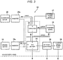
- Fig. 3 is a block diagram of the vehicle power supply system 10 according to the first embodiment of the present invention and schematically illustrates a flow of current when the main driving motor 16 and the sub-driving motors 20 are driven.
- Fig. 4 is a block diagram of the vehicle power supply system 10 according to the first embodiment of the present invention and schematically illustrates a flow of current when the electric charge stored in the capacitor 22 is discharged at the time of a collision of the vehicle 1.
- the battery 18 and the capacitor 22 are connected in series in the vehicle power supply system 10 according to the embodiment. That is, in the embodiment, the battery 18 and the capacitor 22 are electrically connected in series by connecting the positive terminal of the battery 18 and the negative terminal of the capacitor 22 to each other. The negative terminal of the battery 18 and the positive terminal of the capacitor 22 may be connected to each other. In addition, the negative terminal of the battery 18 is connected to the body ground of the vehicle 1.
- the rated voltage of the battery 18 is particularly set to 48 V or about 48 V, which is lower than the lower limit voltage (50 V or about 50 V) of the external power supply 17, and the rated voltage of the capacitor 22 is particularly set to 72 V or about 72 V, which is higher than the lower limit voltage of the external power supply 17.
- JNCAP Japanese New Car Assessment Program
- This electric shock protection performance test is defined to prevent occupants from receiving an electric shock if a collision accident were to occur in an electric vehicle or an electric hybrid vehicle.
- this electric shock protection performance test is targeted for automobiles having an electric motor with an operating voltage of 30 VAC or more, or 60 VDC or more.
- residual voltage measurement which is one evaluation item of this electric shock protection performance test, the residual voltage of high-voltage components after 5 to 60 seconds from a collision should be 30 VAC or less, or 60 VDC or less.
- the rated voltage 48 V of the battery 18 is lower than the predetermined voltage (referred to below as the regulated voltage) 60 V defined as the high voltage by JNCAP, so this rated voltage has no risk associated with the high voltage.
- the rated voltage 72 V of the capacitor 22 is higher than the regulated voltage 60 V, so this rated voltage is regulated as a high-voltage component by JNCAP.
- the rated voltage of the battery 18 means the maximum value of the operating voltage under general conditions and the rated voltage of the capacitor 22 represents the maximum voltage given to the capacitor 22 in this specification.
- the average operating voltage when a battery is discharged under general conditions is referred to as the nominal voltage of the battery.
- the rated voltage of the battery 18 is set to a value lower than the rated voltage of the capacitor 22, the electric charge (coulomb) storable in the battery 18 is more than the electric charge storable in the capacitor 22.
- the battery 18 Since the rated voltage of the battery 18 is set to a value lower than the regulated voltage in the embodiment, the battery 18 solely is not regulated as a high-voltage component. In contrast, since the voltage between the negative terminal of the battery 18 and the positive terminal of the capacitor 22 exceeds the regulated voltage when the battery 18 and the capacitor 22 are connected in series, the components are restricted as high-voltage components.
- the external power supply 17 can directly charge the battery 18 and the capacitor 22. Accordingly, as illustrated in Fig. 2 , during charge by the external power supply 17, the DC current from the external power supply 17 flows to the capacitor 22 and the battery 18 and charges the capacitor 22 and the battery 18.
- the charging device 19 is connected to the capacitor 22 and the battery 18, respectively, to control the charge of the capacitor 22 and the battery 18. The specific structure and operation of the charging device 19 will be described later.
- the charging device 19 may have a DC-to-DC converter so as to lower the voltage of the electric charge stored in the capacitor 22 and charge the battery 18 with the voltage or raise the voltage of the electric charge stored in the battery 18 and charge the capacitor 22 with the voltage. Since the charging device 19 has the DC-to-DC converter connected to the battery 18 and the capacitor 22 as described above, electric charge can be exchanged between the battery 18 and the capacitor 22. This can rapidly charge the battery 18 by lowering the voltage of the electric charge stored in the capacitor 22 while suppressing the degradation of the battery 18 when the vehicle 1 collides and the inter-terminal voltage of the capacitor 22 can be lowered.
- electric power is particularly supplied via different paths to drive the main driving motor 16 and the sub-driving motors 20.
- the main driving motor 16 is particularly driven by a relatively low voltage of about 48 V, electric power is directly supplied from the battery 18 to the inverter 16a for the main driving motor 16. That is, the positive terminal and the negative terminal of the battery 18 are connected to the inverter 16a and the DC voltage of the battery 18 is applied to the inverter 16a.
- the sub-driving motors 20 are driven by a relatively high voltage of about 120 V, electric power is particularly supplied from the battery 18 and/or the capacitor 22 to the inverter 20a for the sub-driving motors 20.
- the positive terminal of the capacitor 22 and the negative terminal of the battery 18 are connected to the inverter 20a and the total of the voltage of the battery 18 and the voltage of the capacitor 22 is applied to the inverter 20a.
- the capacitor 22 is charged with the electric charge stored in the battery 18 by the charging device 19.
- the inter-terminal voltage of the capacitor 22 is raised and the voltage required to drive the sub-driving motors 20 is obtained.
- the electric power obtained by lowering the output voltage of the battery 18 through a DC-to-DC converter 26 is supplied to a 12-V system vehicle-mounted device 28 installed in the vehicle 1.
- the charging device 19 functions as a capacitor discharging device that discharges the electric charge stored in the capacitor 22 and charges the battery 18 with the discharged electric charge.
- the kinetic energy of the vehicle 1 is regenerated by the main driving motor 16 to generate electric power.
- the output voltage from the main driving motor 16 is applied between the positive terminal and the negative terminal of the battery 18 and the battery 18 is charged.
- the sub-driving motors 20 also perform regeneration to generate electric power.
- the output voltages from the sub drive motors 20 are applied between the positive terminal of the capacitor 22 and the negative terminal of the battery 18, and the battery 18 and the capacitor 22 are charged.
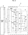
- Fig. 5 illustrates the circuit of the vehicle power supply system 10 according to the embodiment.
- Fig. 6 is a time chart illustrating the operation when the vehicle power supply system 10 according to the embodiment is charged by the external power supply.
- Fig. 7 illustrates the state of the circuit when the vehicle power supply system 10 according to the embodiment is charged by the external power supply.
- Fig. 8 is a time chart illustrating the operation when the capacitor is charged in the vehicle power supply system 10 according to the embodiment.
- Fig. 9 illustrates the state of the circuit when the capacitor is charged in the vehicle power supply system 10 according to the embodiment.
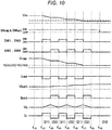
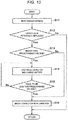
- Fig. 10 is a time chart illustrating the operation when the battery is charged with the electric charge of the capacitor at the time of a collision in the vehicle power supply system 10 according to the embodiment.
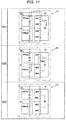
- Fig. 11 illustrates the state of the circuit when the battery is charged with the electric charge of the capacitor at the time of a collision in the vehicle power supply system 10 according to the embodiment.
- the vehicle power supply system 10 is connected to the electric cable 17a of the external power supply 17 via the power feeding port 23 so that the vehicle power supply system 10 can be charged by the external power supply 17.
- the vehicle power supply system 10 includes the battery 18, the capacitor 22, and the charging device 19 and the battery 18 and the capacitor 22 are charged with electric power from the external power supply 17.
- the charging device 19 since the charging device 19 discharges the electric charge of the capacitor 22 and charges the battery 18 with the discharged electric charge when the vehicle collides in the vehicle power supply system 10 according to the embodiment, the charging device 19 functions as a capacitor discharging device.
- the battery 18 and the capacitor 22 are electrically connected in series by connecting the positive terminal of the battery 18 to the negative terminal of the capacitor 22.
- a switch SWbatt is particularly connected to the positive terminal of the battery 18 and a switch SWcap is particularly connected to the positive terminal of the capacitor 22 so as to switch between the connection and disconnection of the battery 18 and the capacitor 22.
- the charging device 19 is connected in parallel to the battery 18 and the capacitor 22 connected in series.
- the charging device 19 particularly includes four switches connected in series in the following order: switches SW1, SW2, SW3, and SW4.
- One end of the switch SW1 is connected to the positive terminal of the capacitor 22 and one end of the switch SW4 is connected to the negative terminal of the battery 18.
- the connection point between the switches SW2 and SW3 is connected to the connection point between the battery 18 and the capacitor 22.
- the opening and closing of the switches SW1 to SW4 and the switches SWbatt and SWcap provided in the battery 18 and capacitor 22 are controlled by a charge controller 19a included in the charging device 19.
- the charge controller 19a which is a controller, may include a microprocessor, a memory, an interface circuit, programs for operating these components (not illustrated), and the like.
- a charge capacitor 19b is connected between the connection point between the switches SW1 and SW2 and the connection point between the switches SW3 and SW4. It should be noted here that semiconductor switches are adopted as these switches in the embodiment, but relays having mechanical contacts may also be used as these switches.
- Fig. 6 and Fig. 7 illustrate the case in which the total of the inter-terminal voltage of the battery 18 and the inter-terminal voltage of the capacitor 22 is equal to or more than the lower limit voltage above which charge by the external power supply 17 is enabled.
- Fig. 6 is a time chart illustrating the operation of the vehicle power supply system 10 when the external power supply 17 charges the battery 18 and the capacitor 22.
- Fig. 6 illustrates, from the top, the voltage Vin input from the external power supply 17, the open-close states of the switches SWbatt and SWcap, the open-close states of the switches SW1 and SW3, and the open-close states of the switches SW2 and SW4.
- Fig. 6 further illustrates an inter-terminal voltage Vcap (voltage between the positive terminal and the negative terminal of the capacitor 22) of the capacitor 22, current Icap flowing through the capacitor 22, an inter-terminal voltage Vbatt of the battery 18, current Ibatt flowing through the battery 18, the inter-terminal voltage Vc of the charge capacitor 19b, and current Ic flowing through the charge capacitor 19b.
- Vcap voltage between the positive terminal and the negative terminal of the capacitor 22
- Fig. 7 illustrates the states of the switches and a flow of current when the external power supply 17 charges the battery 18 and the capacitor 22.
- the switches are sequentially set to the state of stage (1) illustrated in the upper part, the state of stage (2) illustrated in the middle part, and the state of stage (3) illustrated in the lower part in Fig. 7 during charge by the external power supply 17.
- the charge controller 19a turns on (closed state) the switches SWbatt and SWcap and turns off (open state) the switches SW1 to SW4.
- the battery 18 and the capacitor 22 are connected to the external power supply 17 and the charging device 19 is disconnected from the external power supply 17.
- the current supplied from the external power supply 17 flows into the capacitor 22 and the battery 18 (current Icap and current Ibatt > 0) to charge the capacitor 22 and the battery 18.
- the inter-terminal voltage Vcap of the capacitor 22 and the inter-terminal voltage Vbatt of the battery 18 are raised accordingly.
- the inter-terminal voltage Vcap of the capacitor 22 increases more immediately than the inter-terminal voltage Vbatt of the battery 18. Therefore, the inter-terminal voltage Vcap of the capacitor 22 is raised close to the rated voltage of the capacitor 22 at time t 2 .
- the charge controller 19a turns on the switches SW1 and SW3 at time t 2 (the switches SWbatt and SWcap stay on and the switches SW2 and SW4 stay off). This puts the vehicle power supply system 10 in the state of stage (2) illustrated in the middle part in Fig. 7 . In this state, the current from the external power supply 17 flows into the charge capacitor 19b of the charging device 19 and the electric charge stored in the capacitor 22 is discharged (current Icap ⁇ 0) and then flows into the charge capacitor 19b (current Ic > 0). This raises the inter-terminal voltage Vc of the charge capacitor 19b and lowers the inter-terminal voltage Vcap of the capacitor 22. This puts the capacitor 22 in a chargeable state again.
- the voltage that is the total of the inter-terminal voltage Vbatt of the battery 18 and the inter-terminal voltage Vcap of the capacitor 22 is kept at a voltage equal to or higher than the lower limit voltage above which charge by the external power supply 17 is enabled even in the state at time t 3 in which the voltage of the capacitor 22 is lowered.
- the charge controller 19a turns off the switches SW1 and SW3 and turns on the switches SW2 and SW4 at time t 3 (the switches SWbatt and SWcap stay on). This puts the vehicle power supply system 10 in the state of stage (3) illustrated in the lower part in Fig. 7 . In this state, the current from the external power supply 17 flows into the capacitor 22 and the battery 18 to charge the capacitor 22 and the battery 18. In addition, the electric charge stored in the charge capacitor 19b also passes through the switches SW2 and SWbatt to charge the battery 18. This raises the inter-terminal voltage Vcap of the capacitor 22 and the inter-terminal voltage Vbatt of the battery 18 and lowers the inter-terminal voltage Vc of the charge capacitor 19b.
- the charge controller 19a puts the vehicle power supply system 10 in the state of stage (2) illustrated in the middle part in Fig. 7 again by switching the switches at time t 4 .
- the inter-terminal voltage Vcap of the capacitor 22 is lowered and the inter-terminal voltage Vc of the charge capacitor 19b is raised (the inter-terminal voltage Vbatt of the battery 18 is substantially constant).
- the charge controller 19a switches the switches to the state of stage (3) illustrated in the lower part in Fig. 7 at time t 5 , raises the inter-terminal voltages of the capacitor 22 and the battery 18, and lowers the inter-terminal voltage Vc of the charge capacitor 19b.
- the charge controller 19a alternately switches between the state of stage (2) and the state of stage (3) and raises the inter-terminal voltage Vbatt of the battery 18 (charges the battery 18).
- the charge controller 19a ends the charge of the capacitor 22 and the battery 18.
- Fig. 8 is a time chart illustrating the operation of the vehicle power supply system 10 when the battery 18 charges the capacitor 22.
- Fig. 8 illustrates, from the top, the total Vin of the inter-terminal voltages of the battery 18 and the capacitor 22, the open-close states of the switches SWbatt and SWcap, the open-close states of the switches SW1 and SW3, and the open-close states of the switches SW2 and SW4.
- Fig. 8 further illustrates the inter-terminal voltage Vcap of the capacitor 22, the current Icap flowing through the capacitor 22, the inter-terminal voltage Vbatt of the battery 18, the current Ibatt flowing through the battery 18, the inter-terminal voltage Vc of the charge capacitor 19b, and the current Ic flowing through the charge capacitor 19b.
- Fig. 9 illustrates the states of the switches and a flow of current when the capacitor 22 is charged with the electric charge of the battery 18.
- the switches are sequentially set to the state of stage (11) illustrated in the upper part, the state of stage (12) illustrated in the middle part, and the state of stage (13) illustrated in the lower part in Fig. 9 while the capacitor 22 is charged.
- the capacitor 22 is charged to increase the total voltage.
- the charge controller 19a turns on (closed state) the switches SWbatt and SWcap at time t 11 to start the charge of the capacitor 22.
- the charge controller 19a turns on the switches SW2 and SW4 at time t 12 (the switches SW1 and SW3 stay off (open state)). This puts the vehicle power supply system 10 in the state of stage (11) illustrated in the upper part in Fig. 9 .
- the charge controller 19a When the inter-terminal voltage Vc of the charge capacitor 19b is raised to a predetermined voltage, the charge controller 19a turns on the switches SW1 and SW3 at time t 13 and turns off the switches SW2 and SW4 (the switches SWbatt and SWcap stay on) at time t 13 .
- the current (current Ic ⁇ 0) discharged from the charge capacitor 19b of the charging device 19 flows into the capacitor 22 (current Icap > 0).
- the total Vin of the inter-terminal voltages of the capacitor 22 and the battery 18 is raised.
- the charge controller 19a When the inter-terminal voltage Vc of the charge capacitor 19b is lowered to a predetermined voltage, the charge controller 19a turns off the switches SW1 and SW3 and turns on the switches SW2 and SW4 at time t 14 (the switches SWbatt and SWcap stay on). This returns the vehicle power supply system 10 to the state of stage (11) illustrated in the upper part in Fig. 9 . In this state, the current from the battery 18 flows into the charge capacitor 19b to charge the charge capacitor 19b as described above. This raises the inter-terminal voltage Vc of the charge capacitor 19b and slightly lowers the inter-terminal voltage Vbatt of the battery 18.
- the charge controller 19a puts the vehicle power supply system 10 in the state of stage (12) illustrated in the middle part in Fig. 9 again by switching the switches at time t 15 .
- the inter-terminal voltage Vc of the charge capacitor 19b is lowered and the inter-terminal voltage Vcap of the capacitor 22 is raised (the inter-terminal voltage Vbatt of the battery 18 is substantially constant).
- the total Vin of the inter-terminal voltages of the capacitor 22 and the battery 18 is further raised.
- the charge controller 19a alternately switches between the state of stage (11) and the state of stage (12) to raise the inter-terminal voltage Vcap of the capacitor 22 and the total Vin of the inter-terminal voltages of the capacitor 22 and the battery 18 (charge the capacitor 22). That is, the electric charge stored in the battery 18 is discharged and supplied to the capacitor 22 by alternately repeating stage (11) and stage (12) in Fig. 9 , and the inter-terminal voltage Vcap of the capacitor 22 is raised. In contrast, although the electric charge of the battery 18 is discharged, reduction in the inter-terminal voltage of the battery 18 is slight because the capacity of the battery 18 is sufficiently large. Accordingly, the total Vin of the inter-terminal voltages of the capacitor 22 and the battery 18 can be raised by charging the capacitor 22 with the electric charge of the battery 18.
- the charge controller 19a starts charge from the external power supply 17 at time t 19 .
- the external charge start threshold is set to a value equal to or more than the lower limit voltage above which charge by the external power supply 17 is enabled. That is, the charge controller 19a turns on the switches SWbatt and SWcap and turns off the switches SW1 to SW4 at time t 19 to put the vehicle power supply system 10 in the state of stage (13) illustrated in the lower part in Fig. 9 .
- the operation described with reference to Figs. 8 and 9 above is performed to raise the total of the inter-terminal voltages of the capacitor 22 and the battery 18 to a voltage equal to or more than the lower limit voltage above which charge from the external power supply is enabled.
- the operation described with reference to Figs. 8 and 9 is also performed when the total of the inter-terminal voltages of the capacitor 22 and the battery 18 is raised to apply a necessary voltage to the sub-driving motors 20.
- the operation described with reference to Fig. 8 and Fig. 9 is also performed when the total of the inter-terminal voltages of the capacitor 22 and the battery 18 is higher than the lower limit voltage.
- the inter-terminal voltage of the capacitor 22 is lowered to a predetermined voltage or less to prevent an electric shock by discharging the electric charge stored in the capacitor 22 and charging the battery 18 with the discharged electric charge.
- this predetermined voltage can be set to various voltages based on high-voltage regulations of various countries. It should be noted here that the operation illustrated in Figs.
- the 10 and 11 is also performed when the inter-terminal voltage of the capacitor 22 is raised close to the rated voltage by charging the capacitor 22 with the electric power regenerated by the sub-driving motors 20. That is, when the inter-terminal voltage of the capacitor 22 is raised to the rated voltage or higher, the capacitor 22 may be degraded. Accordingly, the regenerated electric power is used effectively by charging the battery 18 with the electric charge stored in the capacitor 22.
- Fig. 10 is a time chart illustrating the operation of the vehicle power supply system 10 that discharges the electric charge of the capacitor 22 and charges the battery 18 with the electric charge at the time of a collision.
- Fig. 10 illustrates, from the top, the total Vin of the inter-terminal voltages of the battery 18 and the capacitor 22, the open-close states of the switches SWbatt and SWcap, the open-close states of the switches SW1 and SW3, and the open-close states of the switches SW2 and SW4.
- Fig. 10 illustrates, from the top, the total Vin of the inter-terminal voltages of the battery 18 and the capacitor 22, the open-close states of the switches SWbatt and SWcap, the open-close states of the switches SW1 and SW3, and the open-close states of the switches SW2 and SW4.
- Fig. 11 illustrates the states of the switches and a flow of current when the battery 18 is charged with the electric charge discharged from the capacitor 22.
- the switches are sequentially set to the state of stage (21) illustrated in the upper part in Fig. 11 , the state of stage (22) illustrated in the middle part, and the state of stage (23) illustrated in the lower part during discharge from the capacitor 22.
- the control device 24 determines whether the vehicle has collided based particularly on the detection signals from the longitudinal acceleration sensor 24a and the lateral acceleration sensor 24b. That is, when the acceleration detected by the longitudinal acceleration sensor 24a or the lateral acceleration sensor 24b exceeds a predetermined threshold, the control device 24 determines that the vehicle 1 has collided.
- the control device 24 particularly transmits a deployment signal to the air bag (not illustrated) installed in the vehicle 1 to deploy the air bag.
- This air bag deployment signal is also transmitted to the charge controller 19a of the charging device 19 to cause the charge controller 19a, which is a control device, to discharge the electric charge of the capacitor 22 by controlling the charging device 19 that functions as a capacitor discharging device.
- the charge controller 19a when receiving the air bag deployment signal at time t 21 in Fig. 10 , the charge controller 19a particularly needs to lower the inter-terminal voltage Vcap of the capacitor 22 since the inter-terminal voltage Vcap of the capacitor 22 is higher than a predetermined voltage. Accordingly, the charge controller 19a discharges the electric charge stored in the capacitor 22 to lower the voltage of the capacitor 22 to a predetermined voltage or less, and charges the battery 18 with the discharged electric charge to lower the inter-terminal voltage Vcap of the capacitor 22.
- the charge controller 19a particularly turns on the switches SW1 and SW3 at time t 22 (the switch SWbatt and the SWcap stay on (closed state) and the switches SW2 and SW4 particularly stay off (open state)).
- the charge controller 19a When the inter-terminal voltage Vc of the charge capacitor 19b is raised to a predetermined voltage, the charge controller 19a particularly turns on the switches SW2 and SW4 at time t 23 and particularly turns off the switches SW1 and SW3 (the switches SWbatt and SWcap stay on). This puts the vehicle power supply system 10 in the state of stage (22) illustrated in the middle part in Fig. 11 . In this state, the current (current Ic ⁇ 0) discharged from the charge capacitor 19b of the charging device 19 flows into the battery 18 (current Ibatt > 0). This lowers the inter-terminal voltage Vc of the charge capacitor 19b and raises or slightly raises the inter-terminal voltage Vbatt of the battery 18 (the inter-terminal voltage Vcap of the capacitor 22 does not change).
- the charge controller 19a When the inter-terminal voltage Vc of the charge capacitor 19b is lowered to a predetermined voltage, the charge controller 19a particularly turns on the switches SW1 and SW3 and particularly turns off the switches SW2 and SW4 at time t 24 (the switches SWbatt and SWcap stay on). This returns the vehicle power supply system 10 to the state of stage (21) illustrated in the upper part in Fig. 11 . In this state, the current from the capacitor 22 flows into the charge capacitor 19b to charge the charge capacitor 19b as described above. This raises the inter-terminal voltage Vc of the charge capacitor 19b and lowers the inter-terminal voltage Vcap of the capacitor 22.
- the charge controller 19a When the inter-terminal voltage Vc of the charge capacitor 19b is lowered to a predetermined voltage, the charge controller 19a particularly switches the switches at time t 25 and particularly puts the vehicle power supply system 10 in the state of stage (22) illustrated in the middle part in Fig. 11 again. In this state, the inter-terminal voltage Vc of the charge capacitor 19b is lowered and the inter-terminal voltage Vbatt of the battery 18 is raised or raised slightly. After that, particularly the charge controller 19a alternately switches between the state of stage (21) and the state of stage (22), charges the battery 18 with the electric charge stored in the capacitor 22, and lowers the inter-terminal voltage Vcap of the capacitor 22.
- the inter-terminal voltage Vcap of the capacitor 22 is lowered to a predetermined voltage (for example, 60 V) or less by repeating stage (21) and stage (22) in Fig. 11 . It should be noted here that increase in the inter-terminal voltage Vbatt of the battery 18 when the battery 18 is charged with the electric charge discharged from the capacitor 22 is slight and the inter-terminal voltage Vbatt is kept at the rated voltage of the battery 18 or less.
- the charge controller 19a When the inter-terminal voltage Vcap of the capacitor 22 is lowered to the predetermined voltage or less at time t 28 in Fig. 10 , the charge controller 19a particularly puts the vehicle power supply system 10 in the state of stage (23) illustrated in the lower part in Fig. 11 . That is, the charge controller 19a particularly turns off the switches SWbatt and SWcap and particularly turns off the switches SW1 to SW4 at time t 29 . This breaks the connection between the capacitor 22 and the battery 18 electrically connected in series. In this state, the inter-terminal voltage Vcap of the capacitor 22 and the inter-terminal voltage Vbatt of the battery 18 are lowered to the predetermined voltage or less to ensure the safety of occupants against an electric shock.
- Fig. 12 is a flowchart illustrating control by the charge controller 19a when the electric charge of the capacitor 22 is discharged.
- the processing of the flowchart illustrated in Fig. 12 is repeatedly performed at predetermined time intervals by the charge controller 19a while the vehicle power supply system 10 operates.
- step S1 in Fig. 12 various detection signals from the sensors installed in the vehicle 1 are read by the charge controller 19a.
- the detection signals read in step S1 include the inter-terminal voltage Vbatt of the battery 18, the inter-terminal voltage Vcap of the capacitor 22, and the air bag deployment signal transmitted by the control device 24. It should be noted here that the inter-terminal voltages of the battery 18 and the capacitor 22 are also input to the charge controller 19a continuously in chronological order after step S1.
- step S2 a determination is made as to whether the vehicle 1 has collided. That is, when the air bag deployment signal is input from the control device 24, the charge controller 19a determines that the vehicle 1 has collided and performs the processing in step S3 and the subsequent steps to lower the inter-terminal voltage Vcap of the capacitor 22. Alternatively, when the air bag deployment signal is not input, the charge controller 19a determines that the vehicle 1 does not collide, the processing of the flowchart illustrated in Fig. 12 is completed one time. That is, since the vehicle power supply system 10 can operate normally when the vehicle 1 does not collide, the electric charge of the capacitor 22 is not discharged.
- the charge controller 19a determines whether a collision of the vehicle 1 has occurred based on the air bag deployment signal in the embodiment.
- the present invention may be configured to determine whether a collision has occurred by inputting the detection signals of the longitudinal acceleration sensor 24a and the lateral acceleration sensor 24b ( Fig. 1 ) to the charge controller 19a and comparing these signals with predetermined thresholds.
- step S3 a determination is made as to whether the inter-terminal voltage Vcap of the capacitor 22 input in step S1 is higher than a predetermined voltage.
- the processing proceeds to step S4 when the inter-terminal voltage Vcap is higher than the predetermined voltage or the processing proceeds to step S6 when the inter-terminal voltage Vcap is equal to or less than the predetermined voltage.
- step S6 the charge controller 19a breaks the electric connection between the battery 18 and the capacitor 22 (the state of stage (23) in Fig. 11 ).
- step S4 the capacitor 22 is discharged (the state of stage (21) in Fig. 11 ) to lower the inter-terminal voltage Vcap of the capacitor 22 and the battery 18 is charged (the state of stage (22) in Fig. 11 ) with the discharged electric charge.
- step S5 a determination is made as to whether the inter-terminal voltage Vcap of the capacitor 22 is equal to or less than the predetermined voltage.
- the processing returns to step S4 and the capacitor 22 is discharged and the battery 18 charged again.
- the processing in step S4 is repeatedly performed until the inter-terminal voltage Vcap is lowered to the predetermined voltage or less.
- the processing in step S6 is performed and the processing of the flowchart illustrated in Fig. 12 is completed one time. As described above, in step S6, the electric connection between the battery 18 and the capacitor 22 is broken (the state of stage (23) in Fig. 11 ) and the voltages of the individual parts of the vehicle power supply system 10 reach the predetermined voltage or less.
- the charging device 19 which is a capacitor discharging device, discharges the electric charge stored in the capacitor 22 and the battery 18 is charged with the discharged electric charge ( Figs. 10 and 11 ) when the vehicle 1 collides, the electric charge stored in the capacitor 22 can be discharged early and surely. Since the battery 18 has a rated voltage lower than the predetermined voltage, even when the battery is charged with the electric charge discharged from the capacitor 22, the voltage is suppressed to the predetermined voltage or less and there is no risk associated with a high voltage.
- the electric charge storable in the capacitor 22 is less than the electric charge storable in the battery 18, the electric charge stored in the capacitor 22 can be discharged to the battery 18 in a short time.
- the electric charge storable in the battery 18 is greater, even when the battery is charged with the electric charge discharged from the capacitor 22, the inter-terminal voltage of the battery 18 is hardly raised ( Fig. 10 ) and the voltages of the battery 18 and the capacitor 22 can be surely lowered.
- the charging device 19 since the charging device 19 lowers the voltage of the capacitor 22 to the predetermined voltage or less within a predetermined time after occurrence of a collision of the vehicle 1, safety at the time of a collision can be ensured more surely.
- the rated voltage of the battery 18 is set to a value lower than the predetermined voltage
- the electric connection between the battery 18 and the capacitor 22 is broken by the charging device 19 (time t 29 in Fig. 10 and stage (23) in Fig. 11 ). Accordingly, even when the battery 18 and the capacitor 22 are connected in series, since a high-voltage component having a voltage higher than the predetermined voltage is not present after the connection is broken, electric shock protection performance can be ensured sufficiently.
- the inter-terminal voltage Vcap of the capacitor 22 is lowered for the purpose of electric shock protection when the vehicle 1 collides.
- the inter-terminal voltage Vcap of the capacitor 22 is lowered for the purpose of electric shock protection when the capacitor 22 is to be replaced during maintenance. Accordingly, only the difference between the embodiment and the first embodiment will be described below and the structure, operation, and effects similar to those of the first embodiment are not described. It should be noted here that the vehicle power supply system according to the present invention may have both the function of electric shock protection at the time of a collision in the first embodiment and the function of electric shock protection when the capacitor is replaced in the second embodiment.
- Fig. 13 is a flowchart illustrating control by the charge controller 19a when the electric charge is discharged at the time of the replacement of the capacitor 22.
- the processing of the flowchart illustrated in Fig. 13 is repeatedly performed at predetermined time intervals by the charge controller 19a while the vehicle power supply system operates.
- step S11 in Fig. 13 one or more various detection signals from the sensors installed in the vehicle 1 are read by the charge controller 19a.
- the detection signals read in step S11 particularly include the inter-terminal voltage Vbatt of the battery 18, the inter-terminal voltage Vcap of the capacitor 22, and a signal particularly indicating the removal of the cover (not illustrated) of the capacitor 22. It should be noted here that the inter-terminal voltages of the battery 18 and the capacitor 22 are also input to the charge controller 19a continuously in chronological order after step S11.
- step S12 a determination is particularly made as to whether a part, e.g. the cover (not illustrated), of the capacitor 22 has been moved or removed from the capacitor 22 and/or the vehicle 1. That is, since the capacitor 22 mounted in the vehicle 1 is covered with the cover (not illustrated), the cover needs to be removed when the capacitor 22 is replaced. Since the portion covered with this cover is provided with a contact switch (not illustrated), a signal indicating the removal of the cover is transmitted from the contact switch to the charge controller 19a when the cover is removed. When receiving the signal indicating the removal of the cover, the charge controller 19a particularly determines that the capacitor 22 is potentially replaced or to be replaced, and performs the processing of step S13 and the subsequent steps to lower the inter-terminal voltage Vcap of the capacitor 22.
- a part e.g. the cover (not illustrated) of the capacitor 22 has been moved or removed from the capacitor 22 and/or the vehicle 1. That is, since the capacitor 22 mounted in the vehicle 1 is covered with the cover (not illustrated), the cover needs to be removed when the capacitor 22 is replaced
- the charge controller 19a determines that the capacitor 22 is not replaced or not to be replaced, and the processing of the flowchart illustrated in Fig. 13 is completed one time. That is, since the capacitor 22 is not replaced or not to be replaced in the state in which the cover (not illustrated) of the capacitor 22 is attached, the inter-terminal voltage Vcap does not need to be lowered by discharging the electric charge of the capacitor 22.
- the charge controller 19a determines whether the capacitor 22 is replaced based on the signal, indicating that the capacitor 22 is potentially replaced, that is transmitted from the contact switch (not illustrated).
- the charge controller 19a may determine that the capacitor 22 is potentially replaced.
- the charge controller 19a may determine that the capacitor 22 is potentially replaced when the place at which the vehicle 1 stops is determined to be a maintenance garage by a car navigation system (not illustrated) mounted on the vehicle 1.
- a signal indicating the connection of the electronic unit (not illustrated) for vehicle maintenance or a signal from the car navigation system (not illustrated) may also be used as the signal indicating that the capacitor 22 is potentially replaced.
- step S13 a determination is made as to whether the inter-terminal voltage Vcap of the capacitor 22 input in step S11 is higher than the predetermined voltage.
- the processing proceeds to step S14 when the inter-terminal voltage Vcap is higher than the predetermined voltage or the processing proceeds to step S16 when the inter-terminal voltage Vcap is equal to or less than the predetermined voltage.
- step S16 the charge controller 19a breaks the electric connection between the battery 18 and the capacitor 22 (the state of stage (23) in Fig. 11 ). That is, since the capacitor 22 can be replaced safely when the inter-terminal voltage Vcap of the capacitor 22 is equal to or less than the predetermined voltage, the inter-terminal voltage Vcap does not need to be lowered and the electric charge of the capacitor 22 is not discharged.
- the capacitor 22 can be replaced without being affected by the electric charge stored in the battery 18.
- the predetermined voltage at the time of a collision in the first embodiment of the present invention may be different from the predetermined voltage when the capacitor 22 is replaced in the embodiment.
- step S14 the capacitor 22 is discharged (the state of stage (21) in Fig. 11 ) to lower the inter-terminal voltage Vcap of the capacitor 22 and the battery 18 is charged with the discharged electric charge (the state of stage (22) in Fig. 11 ).
- step S15 a determination is made as to whether the inter-terminal voltage Vcap of the capacitor 22 has been lowered to the predetermined voltage or less.
- the processing returns to step S14, and the capacitor 22 is discharged and the battery 18 is charged again.
- the processing in step S14 is repeatedly performed until the inter-terminal voltage Vcap is lowered to the predetermined voltage or less.
- the processing in step S16 is performed and the processing of the flowchart illustrated in Fig. 13 is completed one time. As described above, in step S16, the electric connection between the battery 18 and the capacitor 22 is broken (the state of stage (23) in Fig. 11 ) and the voltages of the individual parts of the vehicle power supply system reach the predetermined voltage or less.
- the inter-terminal voltage Vcap is lowered to the predetermined voltage or less within a predetermined time. Accordingly, before the capacitor 22 is actually replaced, the inter-terminal voltage Vcap of the capacitor 22 can be surely lowered to the predetermined voltage or less.
- the charging device 19 which is a capacitor discharging device, discharges the electric charge stored in the capacitor 22 and the battery 18 is charged with the discharged electric charge. Accordingly, the electric charge stored in the capacitor 22 to be replaced can be discharged rapidly and the capacitor 22 can be replaced safely.
- the charging device 19 also lowers the voltage of the capacitor 22 to the predetermined voltage or less within a predetermined time when the capacitor 22 is replaced. Since the voltage of the capacitor 22 is lowered rapidly when the capacitor 22 is replaced, the capacitor 22 can be replaced safely and immediately.
- the vehicle power supply system is used to drive the main driving motor and the sub-driving motors of the vehicle in the embodiments described above, the vehicle power supply system according to the present invention may supply electric power to any electric devices installed in the vehicle.
- the vehicle power supply system can be charged by the external power supply in the embodiments described above, the present invention is applicable to a vehicle power supply system capable of storing only the electric power generated by a motor, an electric generator, and the like installed in the vehicle.
- the present invention is applied to the vehicle power supply system having a battery with a rated voltage of 48 V in the embodiments described above, the present invention may be applied to the vehicle power supply system having a battery with a nominal voltage lower than a predetermined voltage.
Landscapes
- Engineering & Computer Science (AREA)
- Power Engineering (AREA)
- Mechanical Engineering (AREA)
- Transportation (AREA)
- Life Sciences & Earth Sciences (AREA)
- Sustainable Development (AREA)
- Sustainable Energy (AREA)
- Chemical & Material Sciences (AREA)
- Combustion & Propulsion (AREA)
- Electric Propulsion And Braking For Vehicles (AREA)
- Charge And Discharge Circuits For Batteries Or The Like (AREA)
- Hybrid Electric Vehicles (AREA)
Abstract
Description
- The present invention relates to a vehicle power supply system, to a vehicle, and more particularly, to a vehicle power supply system to be installed in a vehicle.
-
JP-A-2016-111754 JP-A-2016-111754 -
JP-A-2016-111754 - When the capacity of the capacitor to be installed in the vehicle is large, however, sufficient discharge may not be performed only by flowing d-axis current through the motor unlike the invention described in
JP-A-2016-111754 - Accordingly, an object of the present invention is discharging the electric charge stored in the capacitor surely and rapidly when, for example, the vehicle collides.
- To solve the problem described above, the present invention provides a vehicle power supply system to be installed in a vehicle, including a battery having a rated voltage lower than a predetermined voltage; a capacitor having a rated voltage higher than the predetermined voltage; a capacitor discharging device that is configured to discharge electric charge stored in the capacitor; and a control device that is configured to control the capacitor discharging device. The control device is configured to control the capacitor discharging device so that the electric charge stored in the capacitor is discharged and the battery is charged with the discharged electric charge when the vehicle collides or when the capacitor is to be replaced.
- According to the present invention configured as described above, since the capacitor discharging device discharges the electric charge stored in the capacitor and the battery is charged with the discharged electric charge when the vehicle collides, the electric charge stored in the capacitor can be discharged early and surely. In addition, since the electric charge stored in the capacitor can be discharged rapidly and the inter-terminal voltage of the capacitor can be lowered quickly when the capacitor is replaced, the capacitor can be replaced immediately. Since the battery has a rated voltage lower than the predetermined voltage, even when the battery is charged with the electric charge discharged from the capacitor, the voltage is suppressed to a regulated voltage or less and there is no risk associated with a high voltage.
- In addition, according to the present invention configured as described above, the capacitor discharging device also discharges the electric charge stored in the capacitor when the capacitor is replaced and the battery is charged with the discharged electric charge. Accordingly, the electric charge stored in the capacitor to be replaced can be discharged rapidly and the capacitor can be replaced safely.
- Particularly, the capacitor discharging device has a DC-to-DC converter and the control device is configured to control the capacitor discharging device so that the DC-to-DC converter lowers a voltage of the electric charge discharged from the capacitor and the battery is charged with the lowered voltage when the vehicle collides or when the capacitor is replaced.
- According to the present invention configured as described above, when the vehicle collides or when the capacitor is replaced, the voltage of the capacitor is lowered by the DC-to-DC converter and the battery is charged with the lowered voltage. Accordingly, even when the inter-terminal voltage of the capacitor and the inter-terminal voltage of the battery are greatly different from each other, the battery can be charged with the electric charge stored in the capacitor while suppressing the degradation of the battery.
- Further particularly, electric charge storable in the capacitor is less than electric charge storable in the battery.
- According to the present invention configured as described above, since the electric charge storable in the capacitor is less than the electric charge storable in the battery, the electric charge stored in the capacitor can be discharged to the battery in a short time. In addition, since the electric charge storable in the battery is greater, even when the battery is charged with the electric charge discharged from the capacitor, the inter-terminal voltage of the battery is hardly raised, the voltages of the battery and the capacitor can be surely lowered.
- Further particularly, the control device is configured to control the capacitor discharging device so that the voltage of the capacitor is lowered to the predetermined voltage or less within a predetermined time from occurrence of a collision of the vehicle or from reception of a signal indicating that the battery is potentially replaced.
- According to the present invention configured as described above, since the capacitor discharging device lowers the voltage of the capacitor to the predetermined voltage or less within the predetermined time from occurrence of a collision of the vehicle, safety at the time of a collision can be ensured more surely.
- According to the present invention configured as described above, the capacitor discharging device also lowers the voltage of the capacitor to the predetermined voltage or less when the capacitor is replaced within the predetermined time. Accordingly, since the voltage of the capacitor is lowered rapidly when the capacitor is replaced, the capacitor can be replaced safely and immediately.
- Further particularly, the control device is configured to control the capacitor discharging device so that the electric connection between the battery and the capacitor is broken when the voltage of the capacitor is lowered to the predetermined voltage or less.
- Since the rated voltage of the battery is set to a value less than the predetermined voltage in the present invention, when the voltage of the capacitor is lowered to the predetermined voltage or less, the electric connection between the battery and the capacitor is broken by the capacitor discharging device. Accordingly, even when the battery and the capacitor are connected in series, since a high-voltage component having a voltage more than the predetermined voltage is not present after the connection is broken, electric shock protection performance can be ensured sufficiently.
- Further particularly, a vehicle includes the above vehicle power supply system.
- Further particularly, the vehicle further includes an electric motor. The battery and/or the capacitor is configured to supply electric power to the electric motor.
- Further particularly, the vehicle further includes a wheel configured to be driven by the electric motor.
- Further particularly, the vehicle further includes a main electric motor and a sub-electric motor. The battery is configured to supply electric power to the main electric motor. The capacitor is configured to supply electric power to the sub-electric motor.
- Further particularly, the battery and the capacitor are configured to supply electric power to the sub-electric motor.
- Further particularly, the vehicle further includes a first wheel configured to be driven by the main electric motor and a second wheel configured to be driven by the sub-electric motor.
- Further particularly, the vehicle further includes an engine. The first wheel is configured to be driven by the main electric motor and the engine.
- Further particularly, the vehicle further includes an acceleration sensor. The control device is configured to control the capacitor discharging device or determine the collision, based on an acceleration of the vehicle.
- Further particularly, the control device is configured to control the capacitor discharging device or determine that the capacitor is to be replaced, if a part of the capacitor is moved or removed from the capacitor (22) and/or the vehicle.
- Further particularly, the control device is configured to control the capacitor discharging device or determine that the capacitor is to be replaced, if a cover of the capacitor is moved or removed from the capacitor and/or the vehicle.
- Further particularly, the control device is configured to control the capacitor discharging device or determine that the capacitor is to be replaced, based on a position of the vehicle.
- In the vehicle power supply system according to the present invention, the electric charge stored in the capacitor can be discharged surely and rapidly when, for example, the vehicle collides.
-
- [
Fig. 1] Fig. 1 illustrates a layout of a vehicle having a vehicle power supply system according to a first embodiment of the present invention. - [
Fig. 2] Fig. 2 is a block diagram of the vehicle power supply system according to the first embodiment of the present invention and schematically illustrates a flow of current during charge by an external power supply. - [
Fig. 3] Fig. 3 is a block diagram of the vehicle power supply system according to the first embodiment of the present invention and schematically illustrates a flow of current when a main driving motor and sub-driving motors are driven. - [
Fig. 4] Fig. 4 is a block diagram of the vehicle power supply system according to the first embodiment of the present invention and schematically illustrates a flow of current when the electric charge stored in the capacitor is discharged at the time of a collision of the vehicle. - [
Fig. 5] Fig. 5 illustrates the circuit of the vehicle power supply system according to the first embodiment of the present invention. - [
Fig. 6] Fig. 6 is a time chart illustrating the operation when the vehicle power supply system according to the first embodiment of the present invention is charged by the external power supply. - [
Fig. 7] Fig. 7 illustrates the state of the circuit when the vehicle power supply system according to the first embodiment of the present invention is charged by the external power supply. - [
Fig. 8] Fig. 8 is a time chart illustrating the operation when a capacitor is charged in the vehicle power supply system according to the first embodiment of the present invention. - [
Fig. 9] Fig. 9 illustrates the state of the circuit when the capacitor is charged in the vehicle power supply system according to the first embodiment of the present invention. - [
Fig. 10] Fig. 10 is a time chart illustrating the operation for charging the battery with the electric charge of the capacitor at the time of a collision in the vehicle power supply system according to the first embodiment of the present invention. - [
Fig. 11] Fig. 11 illustrates the state of the circuit when the battery is charged with the electric charge of the capacitor at the time of a collision in the vehicle power supply system according to the first embodiment of the present invention. - [
Fig. 12] Fig. 12 is a flowchart illustrating control by a charge controller when the electric charge of the capacitor is discharged in the vehicle power supply system according to the first embodiment of the present invention. - [
Fig. 13] Fig. 13 is a flowchart illustrating control by a charge controller when the electric charge of the capacitor is discharged at the time of the replacement of the capacitor in a vehicle power supply system according to a second embodiment of the present invention. - Next, embodiments of the present invention will be described with reference to the attached drawings.
-
Fig. 1 illustrates a layout of a vehicle having a vehicle power supply system according to a first embodiment of the present invention. - As illustrated in
Fig. 1 , avehicle 1 having a vehiclepower supply system 10 according to the first embodiment of the present invention is particularly a so-called an FR (front-engine/rear-drive) vehicle that includes anengine 12, which is an internal combustion engine, in the front part (ahead of the driver's seat) of the vehicle and drives a pair of left and rightrear wheels 2a, which are main driving wheels. In addition, as described later, therear wheels 2a are also driven by a main driving motor and a pair of left and rightfront wheels 2b, which are sub-driving wheels, is driven by sub-driving motors, which are in-wheel motors. - That is, the
vehicle 1 particularly includes theengine 12 that drives therear wheels 2a as a vehicle driving device, apower transmission mechanism 14 that transmits a driving force to therear wheels 2a, amain driving motor 16 that drives therear wheels 2a,sub-driving motors 20 that drive thefront wheels 2b, and acontrol device 24. In addition, thevehicle 1 particularly has aninverter 16a that converts a DC voltage to an AC voltage and drives themain driving motor 16 and aninverter 20a that converts a DC voltage to an AC voltage and drives thesub-driving motors 20. - In addition, the vehicle
power supply system 10 according to the first embodiment of the present invention installed in thevehicle 1 includes abattery 18, acapacitor 22, and a chargingdevice 19 and apower feeding port 23 that receive electric power from anexternal power supply 17 and charging thebattery 18 and thecapacitor 22. The specific structure of the vehiclepower supply system 10 according to the embodiment will be described later. - The
engine 12 is particularly an internal combustion engine that generates a driving force for therear wheels 2a, which are the main driving wheels of thevehicle 1. In the embodiment, an inline four-cylinder engine is particularly adopted as theengine 12 and theengine 12 disposed in the front part of thevehicle 1 drives therear wheels 2a via thepower transmission mechanism 14. - The
power transmission mechanism 14 particularly transmits the driving forces generated by theengine 12 and themain driving motor 16 to therear wheels 2a, which are main driving wheels. As illustrated inFig. 1 , thepower transmission mechanism 14 particularly includes apropeller shaft 14a, which is a power transmission shaft connected to theengine 12 and themain driving motor 16, and atransmission 14b, which is a shifting gearbox. - The
main driving motor 16 is an electric motor that generates a driving force for the main driving wheels, and disposed behind theengine 12 adjacently to theengine 12 on the vehicle body of thevehicle 1. In addition, theinverter 16a is disposed adjacently to themain driving motor 16 and theinverter 16a converts a DC voltage of thebattery 18 to an AC voltage and supplies the AC voltage to themain driving motor 16. In addition, as illustrated inFig. 1 , themain driving motor 16 is particularly connected in series to theengine 12 and a driving force generated by themain driving motor 16 is also transmitted to therear wheels 2a via thepower transmission mechanism 14. In addition, in the embodiment, a 25-kW permanent magnet motor (permanent magnet synchronous motor) driven by 48 V is particularly adopted as themain driving motor 16. - The
sub-driving motors 20 are particularly provided in thefront wheels 2b to generate driving forces for thefront wheels 2b, which are sub-driving wheels. In addition, thesub-driving motors 20 are particularly in-wheel motors and are accommodated in thefront wheels 2b, respectively. In addition, the DC voltage of thecapacitor 22 is converted to an AC voltage by theinverter 20a disposed in atunnel portion 15 and the AC voltage is supplied to thesub-driving motors 20. Furthermore, in the embodiment, thesub-driving motors 20 do not have speed reducers as speed reduction mechanisms, and the driving forces of thesub-driving motors 20 are directly transmitted to thefront wheels 2b, and the wheels are directly driven. In addition, in the embodiment, 17-kW induction motors are adopted as thesub-driving motors 20. - The
battery 18 is an electric storage device in which electric energy for mainly operating themain driving motor 16 is stored. Furthermore, in the embodiment, a 3.5 kWh/48 V lithium ion battery (LIB) is used as thebattery 18. - The
capacitor 22 can store the electric power regenerated by thesub-driving motors 20. Thecapacitor 22 is particularly disposed at a position substantially symmetrical with the plug-intype charging device 19 in the rear part of thevehicle 1 and supplies electric power to thesub-driving motors 20 provided in thefront wheels 2b of thevehicle 1. Thesub-driving motors 20 driven mainly by the electric power stored in thecapacitor 22 is driven by a higher voltage than in themain driving motor 16. - The charging
device 19 is electrically connected to thebattery 18 and thecapacitor 22 and charges thebattery 18 and thecapacitor 22 with the electric power supplied from theexternal power supply 17 such as a charging stand via thepower feeding port 23. Theexternal power supply 17 such as a charging stand generally performs charge with a voltage equal to or more than a predetermined lower limit voltage (for example, 50 V) and the vehiclepower supply system 10 according to the embodiment supports this lower limit voltage. - The
power feeding port 23 is a connector provided on the rear side surface of thevehicle 1 and electrically connected to the chargingdevice 19. The connector of thepower feeding port 23 is connectable to the plug of anelectric cable 17a extending from theexternal power supply 17 such as a charging stand, and electric power is supplied to the chargingdevice 19 via thepower feeding port 23. As described above, the vehiclepower supply system 10 according to the embodiment can charge thebattery 18 and thecapacitor 22 by connecting theexternal power supply 17 that supplies DC electric power to thepower supply port 23 via theelectric cable 17a. - The
control device 24 particularly receives detection signals from one or more various sensors such as a longitudinal (or front-back)acceleration sensor 24a and alateral acceleration sensor 24b. In addition, thecontrol device 24 particularly controls theengine 12, themain driving motor 16, and thesub-driving motors 20 based on the detection signals input from the sensors. Specifically, thecontrol device 24 may include a microprocessor, a memory, an interface circuit, programs for operating these components (not illustrated), and the like. - It should be noted here that the
control device 24 particularly determines whether thevehicle 1 has collided based on acceleration signals detected by thelongitudinal acceleration sensor 24a and thelateral acceleration sensor 24b and, when determining that thevehicle 1 has collided, outputs a control signal for deploying an air bag (not illustrated). In addition, as described later, the air bag deployment signal from thecontrol device 24 is also transmitted to the chargingdevice 19. - Next, the structure and the operation of the vehicle
power supply system 10 according to the first embodiment of the present invention will be described with reference toFigs. 2 to 4 .Fig. 2 is a block diagram of the vehiclepower supply system 10 according to the first embodiment of the present invention and schematically illustrates a flow of current during charge by theexternal power supply 17.Fig. 3 is a block diagram of the vehiclepower supply system 10 according to the first embodiment of the present invention and schematically illustrates a flow of current when themain driving motor 16 and thesub-driving motors 20 are driven.Fig. 4 is a block diagram of the vehiclepower supply system 10 according to the first embodiment of the present invention and schematically illustrates a flow of current when the electric charge stored in thecapacitor 22 is discharged at the time of a collision of thevehicle 1. - First, as illustrated in
Fig. 2 , thebattery 18 and thecapacitor 22 are connected in series in the vehiclepower supply system 10 according to the embodiment. That is, in the embodiment, thebattery 18 and thecapacitor 22 are electrically connected in series by connecting the positive terminal of thebattery 18 and the negative terminal of thecapacitor 22 to each other. The negative terminal of thebattery 18 and the positive terminal of thecapacitor 22 may be connected to each other. In addition, the negative terminal of thebattery 18 is connected to the body ground of thevehicle 1. In the embodiment, the rated voltage of thebattery 18 is particularly set to 48 V or about 48 V, which is lower than the lower limit voltage (50 V or about 50 V) of theexternal power supply 17, and the rated voltage of thecapacitor 22 is particularly set to 72 V or about 72 V, which is higher than the lower limit voltage of theexternal power supply 17. - In Japanese New Car Assessment Program (JNCAP), "Electric shock protection performance test when an electric vehicle etc. collides" is defined. This electric shock protection performance test is defined to prevent occupants from receiving an electric shock if a collision accident were to occur in an electric vehicle or an electric hybrid vehicle. In addition, this electric shock protection performance test is targeted for automobiles having an electric motor with an operating voltage of 30 VAC or more, or 60 VDC or more. In "Residual voltage measurement", which is one evaluation item of this electric shock protection performance test, the residual voltage of high-voltage components after 5 to 60 seconds from a collision should be 30 VAC or less, or 60 VDC or less.
- The rated voltage 48 V of the
battery 18 is lower than the predetermined voltage (referred to below as the regulated voltage) 60 V defined as the high voltage by JNCAP, so this rated voltage has no risk associated with the high voltage. In contrast, the rated voltage 72 V of thecapacitor 22 is higher than the regulated voltage 60 V, so this rated voltage is regulated as a high-voltage component by JNCAP. It should be noted here that the rated voltage of thebattery 18 means the maximum value of the operating voltage under general conditions and the rated voltage of thecapacitor 22 represents the maximum voltage given to thecapacitor 22 in this specification. In addition, the average operating voltage when a battery is discharged under general conditions is referred to as the nominal voltage of the battery. In addition, although the rated voltage of thebattery 18 is set to a value lower than the rated voltage of thecapacitor 22, the electric charge (coulomb) storable in thebattery 18 is more than the electric charge storable in thecapacitor 22. - Since the rated voltage of the
battery 18 is set to a value lower than the regulated voltage in the embodiment, thebattery 18 solely is not regulated as a high-voltage component. In contrast, since the voltage between the negative terminal of thebattery 18 and the positive terminal of thecapacitor 22 exceeds the regulated voltage when thebattery 18 and thecapacitor 22 are connected in series, the components are restricted as high-voltage components. - In addition, since the voltage (voltage between the negative electrode of the
battery 18 and the positive electrode of the capacitor 22) of thecapacitor 22 connected in series to thebattery 18 is equal to or more than the lower limit voltage above which charge by theexternal power supply 17 is enabled, theexternal power supply 17 can directly charge thebattery 18 and thecapacitor 22. Accordingly, as illustrated inFig. 2 , during charge by theexternal power supply 17, the DC current from theexternal power supply 17 flows to thecapacitor 22 and thebattery 18 and charges thecapacitor 22 and thebattery 18. In addition, the chargingdevice 19 is connected to thecapacitor 22 and thebattery 18, respectively, to control the charge of thecapacitor 22 and thebattery 18. The specific structure and operation of the chargingdevice 19 will be described later. - It should be noted here that the charging
device 19 may have a DC-to-DC converter so as to lower the voltage of the electric charge stored in thecapacitor 22 and charge thebattery 18 with the voltage or raise the voltage of the electric charge stored in thebattery 18 and charge thecapacitor 22 with the voltage. Since the chargingdevice 19 has the DC-to-DC converter connected to thebattery 18 and thecapacitor 22 as described above, electric charge can be exchanged between thebattery 18 and thecapacitor 22. This can rapidly charge thebattery 18 by lowering the voltage of the electric charge stored in thecapacitor 22 while suppressing the degradation of thebattery 18 when thevehicle 1 collides and the inter-terminal voltage of thecapacitor 22 can be lowered. - Next, as illustrated in
Fig. 3 , electric power is particularly supplied via different paths to drive themain driving motor 16 and thesub-driving motors 20. First, since themain driving motor 16 is particularly driven by a relatively low voltage of about 48 V, electric power is directly supplied from thebattery 18 to theinverter 16a for themain driving motor 16. That is, the positive terminal and the negative terminal of thebattery 18 are connected to theinverter 16a and the DC voltage of thebattery 18 is applied to theinverter 16a. In contrast, since thesub-driving motors 20 are driven by a relatively high voltage of about 120 V, electric power is particularly supplied from thebattery 18 and/or thecapacitor 22 to theinverter 20a for thesub-driving motors 20. That is, the positive terminal of thecapacitor 22 and the negative terminal of thebattery 18 are connected to theinverter 20a and the total of the voltage of thebattery 18 and the voltage of thecapacitor 22 is applied to theinverter 20a. In addition, when the electric charge of thecapacitor 22 is discharged and the inter-terminal of thecapacitor 22 is lowered, thecapacitor 22 is charged with the electric charge stored in thebattery 18 by the chargingdevice 19. With this, the inter-terminal voltage of thecapacitor 22 is raised and the voltage required to drive thesub-driving motors 20 is obtained. On the other hand, the electric power obtained by lowering the output voltage of thebattery 18 through a DC-to-DC converter 26 is supplied to a 12-V system vehicle-mounteddevice 28 installed in thevehicle 1. - In addition, as illustrated in
Fig. 4 , the electric charge stored in thecapacitor 22 is discharged by the chargingdevice 19 when thevehicle 1 collides, thebattery 18 is charged with the discharged electric charge, and the inter-terminal voltage of thecapacitor 22 is lowered. Accordingly, in the embodiment, the chargingdevice 19 functions as a capacitor discharging device that discharges the electric charge stored in thecapacitor 22 and charges thebattery 18 with the discharged electric charge. - When the
vehicle 1 is braked, the kinetic energy of thevehicle 1 is regenerated by themain driving motor 16 to generate electric power. The output voltage from themain driving motor 16 is applied between the positive terminal and the negative terminal of thebattery 18 and thebattery 18 is charged. In addition, when thevehicle 1 is braked, thesub-driving motors 20 also perform regeneration to generate electric power. The output voltages from thesub drive motors 20 are applied between the positive terminal of thecapacitor 22 and the negative terminal of thebattery 18, and thebattery 18 and thecapacitor 22 are charged. When the electric power regenerated by thesub-driving motors 20 is large and the inter-terminal of thecapacitor 22 is raised to a predetermined value or more, the electric charge stored in thecapacitor 22 is also discharged and thebattery 18 is charged with the electric charge as illustrated inFig. 4 . - Next, the specific structure and operation of the vehicle
power supply system 10 according to the first embodiment of the present invention will be described with reference toFigs. 5 to 11 . -
Fig. 5 illustrates the circuit of the vehiclepower supply system 10 according to the embodiment.Fig. 6 is a time chart illustrating the operation when the vehiclepower supply system 10 according to the embodiment is charged by the external power supply.Fig. 7 illustrates the state of the circuit when the vehiclepower supply system 10 according to the embodiment is charged by the external power supply.Fig. 8 is a time chart illustrating the operation when the capacitor is charged in the vehiclepower supply system 10 according to the embodiment.Fig. 9 illustrates the state of the circuit when the capacitor is charged in the vehiclepower supply system 10 according to the embodiment.Fig. 10 is a time chart illustrating the operation when the battery is charged with the electric charge of the capacitor at the time of a collision in the vehiclepower supply system 10 according to the embodiment.Fig. 11 illustrates the state of the circuit when the battery is charged with the electric charge of the capacitor at the time of a collision in the vehiclepower supply system 10 according to the embodiment. - As illustrated in
Fig. 5 , the vehiclepower supply system 10 according to the embodiment is connected to theelectric cable 17a of theexternal power supply 17 via thepower feeding port 23 so that the vehiclepower supply system 10 can be charged by theexternal power supply 17. In addition, the vehiclepower supply system 10 includes thebattery 18, thecapacitor 22, and the chargingdevice 19 and thebattery 18 and thecapacitor 22 are charged with electric power from theexternal power supply 17. In addition, since the chargingdevice 19 discharges the electric charge of thecapacitor 22 and charges thebattery 18 with the discharged electric charge when the vehicle collides in the vehiclepower supply system 10 according to the embodiment, the chargingdevice 19 functions as a capacitor discharging device. - In addition, as described above, the
battery 18 and thecapacitor 22 are electrically connected in series by connecting the positive terminal of thebattery 18 to the negative terminal of thecapacitor 22. In addition, a switch SWbatt is particularly connected to the positive terminal of thebattery 18 and a switch SWcap is particularly connected to the positive terminal of thecapacitor 22 so as to switch between the connection and disconnection of thebattery 18 and thecapacitor 22. - The charging
device 19 is connected in parallel to thebattery 18 and thecapacitor 22 connected in series. In addition, the chargingdevice 19 particularly includes four switches connected in series in the following order: switches SW1, SW2, SW3, and SW4. One end of the switch SW1 is connected to the positive terminal of thecapacitor 22 and one end of the switch SW4 is connected to the negative terminal of thebattery 18. In addition, the connection point between the switches SW2 and SW3 is connected to the connection point between thebattery 18 and thecapacitor 22. The opening and closing of the switches SW1 to SW4 and the switches SWbatt and SWcap provided in thebattery 18 andcapacitor 22 are controlled by acharge controller 19a included in the chargingdevice 19. Specifically, thecharge controller 19a, which is a controller, may include a microprocessor, a memory, an interface circuit, programs for operating these components (not illustrated), and the like. In addition, acharge capacitor 19b is connected between the connection point between the switches SW1 and SW2 and the connection point between the switches SW3 and SW4. It should be noted here that semiconductor switches are adopted as these switches in the embodiment, but relays having mechanical contacts may also be used as these switches. - Next, the charging of the
battery 18 and thecapacitor 22 by theexternal power source 17 will be described with reference toFigs. 6 and7 . It should be noted here thatFig. 6 andFig. 7 illustrate the case in which the total of the inter-terminal voltage of thebattery 18 and the inter-terminal voltage of thecapacitor 22 is equal to or more than the lower limit voltage above which charge by theexternal power supply 17 is enabled. -
Fig. 6 is a time chart illustrating the operation of the vehiclepower supply system 10 when theexternal power supply 17 charges thebattery 18 and thecapacitor 22.Fig. 6 illustrates, from the top, the voltage Vin input from theexternal power supply 17, the open-close states of the switches SWbatt and SWcap, the open-close states of the switches SW1 and SW3, and the open-close states of the switches SW2 and SW4.Fig. 6 further illustrates an inter-terminal voltage Vcap (voltage between the positive terminal and the negative terminal of the capacitor 22) of thecapacitor 22, current Icap flowing through thecapacitor 22, an inter-terminal voltage Vbatt of thebattery 18, current Ibatt flowing through thebattery 18, the inter-terminal voltage Vc of thecharge capacitor 19b, and current Ic flowing through thecharge capacitor 19b. -
Fig. 7 illustrates the states of the switches and a flow of current when theexternal power supply 17 charges thebattery 18 and thecapacitor 22. The switches are sequentially set to the state of stage (1) illustrated in the upper part, the state of stage (2) illustrated in the middle part, and the state of stage (3) illustrated in the lower part inFig. 7 during charge by theexternal power supply 17. - First, when the
external power supply 17 starts charge at time t1 inFig. 6 , thecharge controller 19a turns on (closed state) the switches SWbatt and SWcap and turns off (open state) the switches SW1 to SW4. This puts the vehiclepower supply system 10 in the state of stage (1) illustrated in the upper part ofFig. 7 . In this state, thebattery 18 and thecapacitor 22 are connected to theexternal power supply 17 and the chargingdevice 19 is disconnected from theexternal power supply 17. With this, the current supplied from theexternal power supply 17 flows into thecapacitor 22 and the battery 18 (current Icap and current Ibatt > 0) to charge thecapacitor 22 and thebattery 18. The inter-terminal voltage Vcap of thecapacitor 22 and the inter-terminal voltage Vbatt of thebattery 18 are raised accordingly. Since the electric charge storable in thecapacitor 22 is less than the electric charge storable in thebattery 18, the inter-terminal voltage Vcap of thecapacitor 22 increases more immediately than the inter-terminal voltage Vbatt of thebattery 18. Therefore, the inter-terminal voltage Vcap of thecapacitor 22 is raised close to the rated voltage of thecapacitor 22 at time t2. - When the inter-terminal voltage Vcap of the
capacitor 22 is raised, thecharge controller 19a turns on the switches SW1 and SW3 at time t2 (the switches SWbatt and SWcap stay on and the switches SW2 and SW4 stay off). This puts the vehiclepower supply system 10 in the state of stage (2) illustrated in the middle part inFig. 7 . In this state, the current from theexternal power supply 17 flows into thecharge capacitor 19b of the chargingdevice 19 and the electric charge stored in thecapacitor 22 is discharged (current Icap < 0) and then flows into thecharge capacitor 19b (current Ic > 0). This raises the inter-terminal voltage Vc of thecharge capacitor 19b and lowers the inter-terminal voltage Vcap of thecapacitor 22. This puts thecapacitor 22 in a chargeable state again. It should be noted here that the voltage that is the total of the inter-terminal voltage Vbatt of thebattery 18 and the inter-terminal voltage Vcap of thecapacitor 22 is kept at a voltage equal to or higher than the lower limit voltage above which charge by theexternal power supply 17 is enabled even in the state at time t3 in which the voltage of thecapacitor 22 is lowered. - When the inter-terminal voltage Vc of the
charge capacitor 19b is raised to a predetermined voltage, thecharge controller 19a turns off the switches SW1 and SW3 and turns on the switches SW2 and SW4 at time t3 (the switches SWbatt and SWcap stay on). This puts the vehiclepower supply system 10 in the state of stage (3) illustrated in the lower part inFig. 7 . In this state, the current from theexternal power supply 17 flows into thecapacitor 22 and thebattery 18 to charge thecapacitor 22 and thebattery 18. In addition, the electric charge stored in thecharge capacitor 19b also passes through the switches SW2 and SWbatt to charge thebattery 18. This raises the inter-terminal voltage Vcap of thecapacitor 22 and the inter-terminal voltage Vbatt of thebattery 18 and lowers the inter-terminal voltage Vc of thecharge capacitor 19b. - When the inter-terminal voltage Vcap of the
capacitor 22 is raised close to the rated voltage, thecharge controller 19a puts the vehiclepower supply system 10 in the state of stage (2) illustrated in the middle part inFig. 7 again by switching the switches at time t4. In this state, the inter-terminal voltage Vcap of thecapacitor 22 is lowered and the inter-terminal voltage Vc of thecharge capacitor 19b is raised (the inter-terminal voltage Vbatt of thebattery 18 is substantially constant). Next, thecharge controller 19a switches the switches to the state of stage (3) illustrated in the lower part inFig. 7 at time t5, raises the inter-terminal voltages of thecapacitor 22 and thebattery 18, and lowers the inter-terminal voltage Vc of thecharge capacitor 19b. After that, thecharge controller 19a alternately switches between the state of stage (2) and the state of stage (3) and raises the inter-terminal voltage Vbatt of the battery 18 (charges the battery 18). When the inter-terminal voltage Vbatt of thebattery 18 is raised to a charge end threshold and the inter-terminal voltage Vcap of thecapacitor 22 is raised close to the rated voltage, thecharge controller 19a ends the charge of thecapacitor 22 and thebattery 18. - Next, charging of the
capacitor 22 with the electric charge stored in thebattery 18 will be described with reference toFigs. 8 and9 . It should be noted here that the operation illustrated inFig. 8 andFig. 9 is performed to enable charge by theexternal power supply 17 when the total of the inter-terminal voltage of thebattery 18 and the inter-terminal voltage of thecapacitor 22 is lowered to a value less than the lower limit voltage above which charge by theexternal power supply 17 is enabled. That is, since charge by theexternal power supply 17 is disabled when the total of the inter-terminal voltages of thebattery 18 and thecapacitor 22 is lowered to a value less than the lower limit voltage, the inter-terminal voltage is raised by charging thecapacitor 22 to enable charge by theexternal power supply 17. In addition, the operation illustrated inFigs. 8 and9 is also performed to raise the inter-terminal voltage of thecapacitor 22 when the electric charge stored in thecapacitor 22 is lowered while thevehicle 1 is traveling. That is, since the voltage necessary to drive thesub-driving motors 20 cannot be obtained when the electric charge stored in thecapacitor 22 is reduced during travel and the inter-terminal voltage is lowered, the necessary voltage is recovered by charging thecapacitor 22. -
Fig. 8 is a time chart illustrating the operation of the vehiclepower supply system 10 when thebattery 18 charges thecapacitor 22.Fig. 8 illustrates, from the top, the total Vin of the inter-terminal voltages of thebattery 18 and thecapacitor 22, the open-close states of the switches SWbatt and SWcap, the open-close states of the switches SW1 and SW3, and the open-close states of the switches SW2 and SW4.Fig. 8 further illustrates the inter-terminal voltage Vcap of thecapacitor 22, the current Icap flowing through thecapacitor 22, the inter-terminal voltage Vbatt of thebattery 18, the current Ibatt flowing through thebattery 18, the inter-terminal voltage Vc of thecharge capacitor 19b, and the current Ic flowing through thecharge capacitor 19b. -
Fig. 9 illustrates the states of the switches and a flow of current when thecapacitor 22 is charged with the electric charge of thebattery 18. The switches are sequentially set to the state of stage (11) illustrated in the upper part, the state of stage (12) illustrated in the middle part, and the state of stage (13) illustrated in the lower part inFig. 9 while thecapacitor 22 is charged. - First, at time t11 in
Fig. 8 , since the total Vin of the inter-terminal voltages of thebattery 18 and thecapacitor 22 is less than the lower limit voltage, thecapacitor 22 is charged to increase the total voltage. Thecharge controller 19a turns on (closed state) the switches SWbatt and SWcap at time t11 to start the charge of thecapacitor 22. In addition, thecharge controller 19a turns on the switches SW2 and SW4 at time t12 (the switches SW1 and SW3 stay off (open state)). This puts the vehiclepower supply system 10 in the state of stage (11) illustrated in the upper part inFig. 9 . In this state, the current (Ibatt < 0) output from thebattery 18 flows into thecharge capacitor 19b of the charging device 19 (Ic > 0) via the switch SWbatt and the switch SW2. This raises the inter-terminal voltage Vc of thecharge capacitor 19b. In contrast, although the inter-terminal voltage Vbatt of thebattery 18 is reduced, the amount of reduction is slight because sufficient electric charge is stored in thebattery 18. - When the inter-terminal voltage Vc of the
charge capacitor 19b is raised to a predetermined voltage, thecharge controller 19a turns on the switches SW1 and SW3 at time t13 and turns off the switches SW2 and SW4 (the switches SWbatt and SWcap stay on) at time t13. This puts the vehiclepower supply system 10 in the state of stage (12) illustrated in the middle part inFig. 9 . In this state, the current (current Ic < 0) discharged from thecharge capacitor 19b of the chargingdevice 19 flows into the capacitor 22 (current Icap > 0). This lowers the inter-terminal voltage Vc of thecharge capacitor 19b and raises the inter-terminal voltage Vcap of the capacitor 22 (the inter-terminal voltage Vbatt of thebattery 18 does not change). As a result, the total Vin of the inter-terminal voltages of thecapacitor 22 and thebattery 18 is raised. - When the inter-terminal voltage Vc of the
charge capacitor 19b is lowered to a predetermined voltage, thecharge controller 19a turns off the switches SW1 and SW3 and turns on the switches SW2 and SW4 at time t14 (the switches SWbatt and SWcap stay on). This returns the vehiclepower supply system 10 to the state of stage (11) illustrated in the upper part inFig. 9 . In this state, the current from thebattery 18 flows into thecharge capacitor 19b to charge thecharge capacitor 19b as described above. This raises the inter-terminal voltage Vc of thecharge capacitor 19b and slightly lowers the inter-terminal voltage Vbatt of thebattery 18. - When the inter-terminal voltage Vc of the
charge capacitor 19b is lowered to a predetermined voltage, thecharge controller 19a puts the vehiclepower supply system 10 in the state of stage (12) illustrated in the middle part inFig. 9 again by switching the switches at time t15. In this state, the inter-terminal voltage Vc of thecharge capacitor 19b is lowered and the inter-terminal voltage Vcap of thecapacitor 22 is raised (the inter-terminal voltage Vbatt of thebattery 18 is substantially constant). As a result, the total Vin of the inter-terminal voltages of thecapacitor 22 and thebattery 18 is further raised. After that, thecharge controller 19a alternately switches between the state of stage (11) and the state of stage (12) to raise the inter-terminal voltage Vcap of thecapacitor 22 and the total Vin of the inter-terminal voltages of thecapacitor 22 and the battery 18 (charge the capacitor 22). That is, the electric charge stored in thebattery 18 is discharged and supplied to thecapacitor 22 by alternately repeating stage (11) and stage (12) inFig. 9 , and the inter-terminal voltage Vcap of thecapacitor 22 is raised. In contrast, although the electric charge of thebattery 18 is discharged, reduction in the inter-terminal voltage of thebattery 18 is slight because the capacity of thebattery 18 is sufficiently large. Accordingly, the total Vin of the inter-terminal voltages of thecapacitor 22 and thebattery 18 can be raised by charging thecapacitor 22 with the electric charge of thebattery 18. - When the total of the inter-terminal voltages of the
capacitor 22 and thebattery 18 reaches an external charge start threshold at time t18 inFig. 8 , thecharge controller 19a starts charge from theexternal power supply 17 at time t19. It should be noted here that the external charge start threshold is set to a value equal to or more than the lower limit voltage above which charge by theexternal power supply 17 is enabled. That is, thecharge controller 19a turns on the switches SWbatt and SWcap and turns off the switches SW1 to SW4 at time t19 to put the vehiclepower supply system 10 in the state of stage (13) illustrated in the lower part inFig. 9 . With this, the current supplied from theexternal power supply 17 flows into thecapacitor 22 and thebattery 18, and the inter-terminal voltages of thecapacitor 22 and thebattery 18 are raised. It should be noted here that a shift is made to the operation described inFigs. 6 and7 when the inter-terminal voltage Vcap of thecapacitor 22 reaches a predetermined voltage after time t19 to charge thebattery 18. - The operation described with reference to
Figs. 8 and9 above is performed to raise the total of the inter-terminal voltages of thecapacitor 22 and thebattery 18 to a voltage equal to or more than the lower limit voltage above which charge from the external power supply is enabled. However, the operation described with reference toFigs. 8 and9 is also performed when the total of the inter-terminal voltages of thecapacitor 22 and thebattery 18 is raised to apply a necessary voltage to thesub-driving motors 20. In this case, the operation described with reference toFig. 8 andFig. 9 is also performed when the total of the inter-terminal voltages of thecapacitor 22 and thebattery 18 is higher than the lower limit voltage. - Next, the discharge of the
capacitor 22 when thevehicle 1 collides will be described with reference toFigs. 10 and11 . That is, the inter-terminal voltage of thecapacitor 22 is lowered to a predetermined voltage or less to prevent an electric shock by discharging the electric charge stored in thecapacitor 22 and charging thebattery 18 with the discharged electric charge. By setting this predetermined voltage to the regulated voltage (60 V) defined by JNCAP or lower, the demand by JNCAP can be met. In addition, the predetermined voltage can be set to various voltages based on high-voltage regulations of various countries. It should be noted here that the operation illustrated inFigs. 10 and11 is also performed when the inter-terminal voltage of thecapacitor 22 is raised close to the rated voltage by charging thecapacitor 22 with the electric power regenerated by thesub-driving motors 20. That is, when the inter-terminal voltage of thecapacitor 22 is raised to the rated voltage or higher, thecapacitor 22 may be degraded. Accordingly, the regenerated electric power is used effectively by charging thebattery 18 with the electric charge stored in thecapacitor 22. -
Fig. 10 is a time chart illustrating the operation of the vehiclepower supply system 10 that discharges the electric charge of thecapacitor 22 and charges thebattery 18 with the electric charge at the time of a collision.Fig. 10 illustrates, from the top, the total Vin of the inter-terminal voltages of thebattery 18 and thecapacitor 22, the open-close states of the switches SWbatt and SWcap, the open-close states of the switches SW1 and SW3, and the open-close states of the switches SW2 and SW4.Fig. 10 further illustrates the inter-terminal voltage Vcap of thecapacitor 22, the current Icap flowing through thecapacitor 22, the inter-terminal voltage Vbatt of thebattery 18, the current Ibatt flowing through thebattery 18, the inter-terminal voltage Vc of thecharge capacitor 19b, and the current Ic flowing through thecharge capacitor 19b. -
Fig. 11 illustrates the states of the switches and a flow of current when thebattery 18 is charged with the electric charge discharged from thecapacitor 22. The switches are sequentially set to the state of stage (21) illustrated in the upper part inFig. 11 , the state of stage (22) illustrated in the middle part, and the state of stage (23) illustrated in the lower part during discharge from thecapacitor 22. - As described above, the control device 24 (
Fig. 1 ) determines whether the vehicle has collided based particularly on the detection signals from thelongitudinal acceleration sensor 24a and thelateral acceleration sensor 24b. That is, when the acceleration detected by thelongitudinal acceleration sensor 24a or thelateral acceleration sensor 24b exceeds a predetermined threshold, thecontrol device 24 determines that thevehicle 1 has collided. When determining that thevehicle 1 has collided, thecontrol device 24 particularly transmits a deployment signal to the air bag (not illustrated) installed in thevehicle 1 to deploy the air bag. This air bag deployment signal is also transmitted to thecharge controller 19a of the chargingdevice 19 to cause thecharge controller 19a, which is a control device, to discharge the electric charge of thecapacitor 22 by controlling the chargingdevice 19 that functions as a capacitor discharging device. - First, when receiving the air bag deployment signal at time t21 in
Fig. 10 , thecharge controller 19a particularly needs to lower the inter-terminal voltage Vcap of thecapacitor 22 since the inter-terminal voltage Vcap of thecapacitor 22 is higher than a predetermined voltage. Accordingly, thecharge controller 19a discharges the electric charge stored in thecapacitor 22 to lower the voltage of thecapacitor 22 to a predetermined voltage or less, and charges thebattery 18 with the discharged electric charge to lower the inter-terminal voltage Vcap of thecapacitor 22. Thecharge controller 19a particularly turns on the switches SW1 and SW3 at time t22 (the switch SWbatt and the SWcap stay on (closed state) and the switches SW2 and SW4 particularly stay off (open state)). This puts the vehiclepower supply system 10 in the state of stage (21) illustrated in the upper part inFig. 11 . In this state, the current (Icap < 0) discharged from thecapacitor 22 flows into thecharge capacitor 19b of the charging device 19 (Ic>0) via the switch SWcap and the switch SW1. This raises the inter-terminal voltage Vc of thecharge capacitor 19b and lowers the inter-terminal voltage Vcap of thecapacitor 22. - When the inter-terminal voltage Vc of the
charge capacitor 19b is raised to a predetermined voltage, thecharge controller 19a particularly turns on the switches SW2 and SW4 at time t23 and particularly turns off the switches SW1 and SW3 (the switches SWbatt and SWcap stay on). This puts the vehiclepower supply system 10 in the state of stage (22) illustrated in the middle part inFig. 11 . In this state, the current (current Ic < 0) discharged from thecharge capacitor 19b of the chargingdevice 19 flows into the battery 18 (current Ibatt > 0). This lowers the inter-terminal voltage Vc of thecharge capacitor 19b and raises or slightly raises the inter-terminal voltage Vbatt of the battery 18 (the inter-terminal voltage Vcap of thecapacitor 22 does not change). - When the inter-terminal voltage Vc of the
charge capacitor 19b is lowered to a predetermined voltage, thecharge controller 19a particularly turns on the switches SW1 and SW3 and particularly turns off the switches SW2 and SW4 at time t24 (the switches SWbatt and SWcap stay on). This returns the vehiclepower supply system 10 to the state of stage (21) illustrated in the upper part inFig. 11 . In this state, the current from thecapacitor 22 flows into thecharge capacitor 19b to charge thecharge capacitor 19b as described above. This raises the inter-terminal voltage Vc of thecharge capacitor 19b and lowers the inter-terminal voltage Vcap of thecapacitor 22. - When the inter-terminal voltage Vc of the
charge capacitor 19b is lowered to a predetermined voltage, thecharge controller 19a particularly switches the switches at time t25 and particularly puts the vehiclepower supply system 10 in the state of stage (22) illustrated in the middle part inFig. 11 again. In this state, the inter-terminal voltage Vc of thecharge capacitor 19b is lowered and the inter-terminal voltage Vbatt of thebattery 18 is raised or raised slightly. After that, particularly thecharge controller 19a alternately switches between the state of stage (21) and the state of stage (22), charges thebattery 18 with the electric charge stored in thecapacitor 22, and lowers the inter-terminal voltage Vcap of thecapacitor 22. - That is, the inter-terminal voltage Vcap of the
capacitor 22 is lowered to a predetermined voltage (for example, 60 V) or less by repeating stage (21) and stage (22) inFig. 11 . It should be noted here that increase in the inter-terminal voltage Vbatt of thebattery 18 when thebattery 18 is charged with the electric charge discharged from thecapacitor 22 is slight and the inter-terminal voltage Vbatt is kept at the rated voltage of thebattery 18 or less. - When the inter-terminal voltage Vcap of the
capacitor 22 is lowered to the predetermined voltage or less at time t28 inFig. 10 , thecharge controller 19a particularly puts the vehiclepower supply system 10 in the state of stage (23) illustrated in the lower part inFig. 11 . That is, thecharge controller 19a particularly turns off the switches SWbatt and SWcap and particularly turns off the switches SW1 to SW4 at time t29. This breaks the connection between thecapacitor 22 and thebattery 18 electrically connected in series. In this state, the inter-terminal voltage Vcap of thecapacitor 22 and the inter-terminal voltage Vbatt of thebattery 18 are lowered to the predetermined voltage or less to ensure the safety of occupants against an electric shock. It particularly takes a predetermined time from when the air bag deployment signal (during collision) is received at time t21 inFig. 10 until the connection between thecapacitor 22 and thebattery 18 is broken at time t29, in the embodiment. "Electric shock protection performance test when an electric vehicle etc. collides" of JNCAP defines the residual voltage after 5 to 60 seconds from a collision should be 60 VDC or less. Accordingly, by setting the "predetermined time" to a value, for example, shorter than five seconds, the demand of the "electric shock performance test" can be met surely. In addition, various "predetermined times" can be set based on high-voltage regulations of various countries. - Next, the operation of the
charge controller 19a when thecapacitor 22 discharges electric charge at the time of a collision of thevehicle 1 will be described with reference toFig. 12 . -
Fig. 12 is a flowchart illustrating control by thecharge controller 19a when the electric charge of thecapacitor 22 is discharged. The processing of the flowchart illustrated inFig. 12 is repeatedly performed at predetermined time intervals by thecharge controller 19a while the vehiclepower supply system 10 operates. - First, in step S1 in
Fig. 12 , various detection signals from the sensors installed in thevehicle 1 are read by thecharge controller 19a. The detection signals read in step S1 include the inter-terminal voltage Vbatt of thebattery 18, the inter-terminal voltage Vcap of thecapacitor 22, and the air bag deployment signal transmitted by thecontrol device 24. It should be noted here that the inter-terminal voltages of thebattery 18 and thecapacitor 22 are also input to thecharge controller 19a continuously in chronological order after step S1. - Next, in step S2, a determination is made as to whether the
vehicle 1 has collided. That is, when the air bag deployment signal is input from thecontrol device 24, thecharge controller 19a determines that thevehicle 1 has collided and performs the processing in step S3 and the subsequent steps to lower the inter-terminal voltage Vcap of thecapacitor 22. Alternatively, when the air bag deployment signal is not input, thecharge controller 19a determines that thevehicle 1 does not collide, the processing of the flowchart illustrated inFig. 12 is completed one time. That is, since the vehiclepower supply system 10 can operate normally when thevehicle 1 does not collide, the electric charge of thecapacitor 22 is not discharged. It should be noted here that thecharge controller 19a determines whether a collision of thevehicle 1 has occurred based on the air bag deployment signal in the embodiment. In contrast, in a modification, the present invention may be configured to determine whether a collision has occurred by inputting the detection signals of thelongitudinal acceleration sensor 24a and thelateral acceleration sensor 24b (Fig. 1 ) to thecharge controller 19a and comparing these signals with predetermined thresholds. - In addition, in step S3, a determination is made as to whether the inter-terminal voltage Vcap of the
capacitor 22 input in step S1 is higher than a predetermined voltage. The processing proceeds to step S4 when the inter-terminal voltage Vcap is higher than the predetermined voltage or the processing proceeds to step S6 when the inter-terminal voltage Vcap is equal to or less than the predetermined voltage. In step S6, thecharge controller 19a breaks the electric connection between thebattery 18 and the capacitor 22 (the state of stage (23) inFig. 11 ). That is, when the inter-terminal voltage Vcap of thecapacitor 22 is equal to or less than the predetermined voltage even if a collision occurs in thevehicle 1, a high-voltage component having a voltage higher than the predetermined voltage is not present only by breaking the connection between thebattery 18 and thecapacitor 22. - On the other hand, in step S4, the
capacitor 22 is discharged (the state of stage (21) inFig. 11 ) to lower the inter-terminal voltage Vcap of thecapacitor 22 and thebattery 18 is charged (the state of stage (22) inFig. 11 ) with the discharged electric charge. - Next, in step S5, a determination is made as to whether the inter-terminal voltage Vcap of the
capacitor 22 is equal to or less than the predetermined voltage. When the inter-terminal voltage Vcap is higher than the predetermined voltage, the processing returns to step S4 and thecapacitor 22 is discharged and thebattery 18 charged again. The processing in step S4 is repeatedly performed until the inter-terminal voltage Vcap is lowered to the predetermined voltage or less. When the inter-terminal voltage Vcap of thecapacitor 22 is lowered to the predetermined voltage or less, the processing in step S6 is performed and the processing of the flowchart illustrated inFig. 12 is completed one time. As described above, in step S6, the electric connection between thebattery 18 and thecapacitor 22 is broken (the state of stage (23) inFig. 11 ) and the voltages of the individual parts of the vehiclepower supply system 10 reach the predetermined voltage or less. - In the vehicle
power supply system 10 according to the first embodiment of the present invention, since the chargingdevice 19, which is a capacitor discharging device, discharges the electric charge stored in thecapacitor 22 and thebattery 18 is charged with the discharged electric charge (Figs. 10 and11 ) when thevehicle 1 collides, the electric charge stored in thecapacitor 22 can be discharged early and surely. Since thebattery 18 has a rated voltage lower than the predetermined voltage, even when the battery is charged with the electric charge discharged from thecapacitor 22, the voltage is suppressed to the predetermined voltage or less and there is no risk associated with a high voltage. - In addition, in the vehicle
power supply system 10 according to the embodiment, since the electric charge storable in thecapacitor 22 is less than the electric charge storable in thebattery 18, the electric charge stored in thecapacitor 22 can be discharged to thebattery 18 in a short time. In addition, since the electric charge storable in thebattery 18 is greater, even when the battery is charged with the electric charge discharged from thecapacitor 22, the inter-terminal voltage of thebattery 18 is hardly raised (Fig. 10 ) and the voltages of thebattery 18 and thecapacitor 22 can be surely lowered. - Furthermore, in the vehicle
power supply system 10 according to the embodiment, since the chargingdevice 19 lowers the voltage of thecapacitor 22 to the predetermined voltage or less within a predetermined time after occurrence of a collision of thevehicle 1, safety at the time of a collision can be ensured more surely. - In addition, in the vehicle
power supply system 10 according to the embodiment, since the rated voltage of thebattery 18 is set to a value lower than the predetermined voltage, when the voltage of thecapacitor 22 is lowered to the predetermined voltage or less, the electric connection between thebattery 18 and thecapacitor 22 is broken by the charging device 19 (time t29 inFig. 10 and stage (23) inFig. 11 ). Accordingly, even when thebattery 18 and thecapacitor 22 are connected in series, since a high-voltage component having a voltage higher than the predetermined voltage is not present after the connection is broken, electric shock protection performance can be ensured sufficiently. - Next, a vehicle power supply system according to a second embodiment of the present invention will be described with reference to
Fig. 13 . - In the first embodiment described above, the inter-terminal voltage Vcap of the
capacitor 22 is lowered for the purpose of electric shock protection when thevehicle 1 collides. In contrast, in the embodiment, the inter-terminal voltage Vcap of thecapacitor 22 is lowered for the purpose of electric shock protection when thecapacitor 22 is to be replaced during maintenance. Accordingly, only the difference between the embodiment and the first embodiment will be described below and the structure, operation, and effects similar to those of the first embodiment are not described. It should be noted here that the vehicle power supply system according to the present invention may have both the function of electric shock protection at the time of a collision in the first embodiment and the function of electric shock protection when the capacitor is replaced in the second embodiment. -
Fig. 13 is a flowchart illustrating control by thecharge controller 19a when the electric charge is discharged at the time of the replacement of thecapacitor 22. The processing of the flowchart illustrated inFig. 13 is repeatedly performed at predetermined time intervals by thecharge controller 19a while the vehicle power supply system operates. - First, in step S11 in
Fig. 13 , one or more various detection signals from the sensors installed in thevehicle 1 are read by thecharge controller 19a. The detection signals read in step S11 particularly include the inter-terminal voltage Vbatt of thebattery 18, the inter-terminal voltage Vcap of thecapacitor 22, and a signal particularly indicating the removal of the cover (not illustrated) of thecapacitor 22. It should be noted here that the inter-terminal voltages of thebattery 18 and thecapacitor 22 are also input to thecharge controller 19a continuously in chronological order after step S11. - Next, in step S12, a determination is particularly made as to whether a part, e.g. the cover (not illustrated), of the
capacitor 22 has been moved or removed from thecapacitor 22 and/or thevehicle 1. That is, since thecapacitor 22 mounted in thevehicle 1 is covered with the cover (not illustrated), the cover needs to be removed when thecapacitor 22 is replaced. Since the portion covered with this cover is provided with a contact switch (not illustrated), a signal indicating the removal of the cover is transmitted from the contact switch to thecharge controller 19a when the cover is removed. When receiving the signal indicating the removal of the cover, thecharge controller 19a particularly determines that thecapacitor 22 is potentially replaced or to be replaced, and performs the processing of step S13 and the subsequent steps to lower the inter-terminal voltage Vcap of thecapacitor 22. Alternatively, when not receiving the signal indicating the removal of the cover, thecharge controller 19a determines that thecapacitor 22 is not replaced or not to be replaced, and the processing of the flowchart illustrated inFig. 13 is completed one time. That is, since thecapacitor 22 is not replaced or not to be replaced in the state in which the cover (not illustrated) of thecapacitor 22 is attached, the inter-terminal voltage Vcap does not need to be lowered by discharging the electric charge of thecapacitor 22. - In the embodiment, the
charge controller 19a determines whether thecapacitor 22 is replaced based on the signal, indicating that thecapacitor 22 is potentially replaced, that is transmitted from the contact switch (not illustrated). In contrast, in a modification, when an electronic unit (not illustrated) for vehicle maintenance is connected to thecontrol device 24 of thevehicle 1, thecharge controller 19a may determine that thecapacitor 22 is potentially replaced. Alternatively, thecharge controller 19a may determine that thecapacitor 22 is potentially replaced when the place at which thevehicle 1 stops is determined to be a maintenance garage by a car navigation system (not illustrated) mounted on thevehicle 1. Accordingly, a signal indicating the connection of the electronic unit (not illustrated) for vehicle maintenance or a signal from the car navigation system (not illustrated) may also be used as the signal indicating that thecapacitor 22 is potentially replaced. - In addition, in step S13, a determination is made as to whether the inter-terminal voltage Vcap of the
capacitor 22 input in step S11 is higher than the predetermined voltage. The processing proceeds to step S14 when the inter-terminal voltage Vcap is higher than the predetermined voltage or the processing proceeds to step S16 when the inter-terminal voltage Vcap is equal to or less than the predetermined voltage. In step S16, thecharge controller 19a breaks the electric connection between thebattery 18 and the capacitor 22 (the state of stage (23) inFig. 11 ). That is, since thecapacitor 22 can be replaced safely when the inter-terminal voltage Vcap of thecapacitor 22 is equal to or less than the predetermined voltage, the inter-terminal voltage Vcap does not need to be lowered and the electric charge of thecapacitor 22 is not discharged. In addition, by breaking the electric connection between thebattery 18 and thecapacitor 22 in step S16, thecapacitor 22 can be replaced without being affected by the electric charge stored in thebattery 18. It should be noted here that the predetermined voltage at the time of a collision in the first embodiment of the present invention may be different from the predetermined voltage when thecapacitor 22 is replaced in the embodiment. - On the other hand, in step S14, the
capacitor 22 is discharged (the state of stage (21) inFig. 11 ) to lower the inter-terminal voltage Vcap of thecapacitor 22 and thebattery 18 is charged with the discharged electric charge (the state of stage (22) inFig. 11 ). - Next, in step S15, a determination is made as to whether the inter-terminal voltage Vcap of the
capacitor 22 has been lowered to the predetermined voltage or less. When the inter-terminal voltage Vcap has not lowered to the predetermined voltage or less, the processing returns to step S14, and thecapacitor 22 is discharged and thebattery 18 is charged again. After that, the processing in step S14 is repeatedly performed until the inter-terminal voltage Vcap is lowered to the predetermined voltage or less. When the inter-terminal voltage Vcap of thecapacitor 22 is lowered to the predetermined voltage or less, the processing in step S16 is performed and the processing of the flowchart illustrated inFig. 13 is completed one time. As described above, in step S16, the electric connection between thebattery 18 and thecapacitor 22 is broken (the state of stage (23) inFig. 11 ) and the voltages of the individual parts of the vehicle power supply system reach the predetermined voltage or less. - In the embodiment, after a determination is made as to whether the cover (not illustrated) of the
capacitor 22 has been removed in step S12, the inter-terminal voltage Vcap is lowered to the predetermined voltage or less within a predetermined time. Accordingly, before thecapacitor 22 is actually replaced, the inter-terminal voltage Vcap of thecapacitor 22 can be surely lowered to the predetermined voltage or less. - In the vehicle power supply system according to the second embodiment, when the
capacitor 22 is replaced, the chargingdevice 19, which is a capacitor discharging device, discharges the electric charge stored in thecapacitor 22 and thebattery 18 is charged with the discharged electric charge. Accordingly, the electric charge stored in thecapacitor 22 to be replaced can be discharged rapidly and thecapacitor 22 can be replaced safely. - In addition, in the vehicle power supply system according to the embodiment, the charging
device 19 also lowers the voltage of thecapacitor 22 to the predetermined voltage or less within a predetermined time when thecapacitor 22 is replaced. Since the voltage of thecapacitor 22 is lowered rapidly when thecapacitor 22 is replaced, thecapacitor 22 can be replaced safely and immediately. - Although embodiments of the present invention have been described above, various modifications can be made to these embodiments. In particular, although the vehicle power supply system is used to drive the main driving motor and the sub-driving motors of the vehicle in the embodiments described above, the vehicle power supply system according to the present invention may supply electric power to any electric devices installed in the vehicle. In addition, although the vehicle power supply system can be charged by the external power supply in the embodiments described above, the present invention is applicable to a vehicle power supply system capable of storing only the electric power generated by a motor, an electric generator, and the like installed in the vehicle. Furthermore, although the present invention is applied to the vehicle power supply system having a battery with a rated voltage of 48 V in the embodiments described above, the present invention may be applied to the vehicle power supply system having a battery with a nominal voltage lower than a predetermined voltage.
-
- 1:
- vehicle
- 2a:
- rear wheel
- 2b:
- front wheel
- 10:
- vehicle power supply system
- 12:
- engine
- 14:
- power transmission mechanism
- 14a:
- propeller shaft
- 14b:
- transmission
- 16:
- main driving motor
- 16a:
- inverter
- 17:
- external power supply
- 17a:
- electric cable
- 18:
- battery
- 19:
- charging device (capacitor discharging device)
- 19a:
- charge controller (control device)
- 19b:
- charge capacitor
- 20:
- sub-driving motor
- 20a:
- inverter
- 22:
- capacitor
- 23:
- power feeding port (power feeding device)
- 24:
- control device
- 24a:
- longitudinal acceleration sensor
- 24b:
- lateral acceleration sensor
- 26:
- DC-to-DC converter
- 28:
- vehicle-mounted device
Claims (15)
- A vehicle power supply system (10) to be installed in a vehicle (1), comprising:a battery (18) having a rated voltage lower than a predetermined voltage;a capacitor (22) having a rated voltage higher than the predetermined voltage;a capacitor discharging device (19) that is configured to discharge electric charge stored in the capacitor (22); anda control device (19a, 24) that is configured to control the capacitor discharging device (19),wherein the control device (19a, 24) is configured to control the capacitor discharging device (19) so that the electric charge stored in the capacitor (22) is discharged and the battery (18) is charged with the discharged electric charge when the vehicle (1) collides or when the capacitor (22) is to be replaced.
- The vehicle power supply system (10) according to claim 1, wherein
the capacitor discharging device (19) has a DC-to-DC converter, and
the control device (19a, 24) is configured to control the capacitor discharging device (19) so that the DC-to-DC converter lowers a voltage of the electric charge discharged from the capacitor (22) and the battery (18) is charged with the lowered voltage when the vehicle (1) collides or when the capacitor (22) is to be replaced. - The vehicle power supply system (10) according to claim 1 or 2,
wherein electric charge storable in the capacitor (22) is less than electric charge storable in the battery (18). - The vehicle power supply system (10) according to any one of the preceding claims,
wherein the control device (19a, 24) is configured to control the capacitor discharging device (19) so that the voltage of the capacitor (22) is lowered to the predetermined voltage or less within a predetermined time from occurrence of a collision of the vehicle (1) or from reception of a signal indicating that the battery (18) is potentially replaced. - The vehicle power supply system (10) according to claim 4,
wherein the control device (19a, 24) is configured to control the capacitor discharging device (19) so that electric connection between the battery (18) and the capacitor (22) is broken when the voltage of the capacitor (22) is lowered to the predetermined voltage or less. - A vehicle (1) comprising the vehicle power supply system (10) according to any one of the preceding claims.
- The vehicle (1) according to claim 6, further comprising an electric motor (16, 20), wherein
the battery (18) and/or the capacitor (22) is configured to supply electric power to the electric motor (16, 20). - The vehicle (1) according to claim 7, further comprising a wheel (2a, 2b) configured to be driven by the electric motor (16, 20).
- The vehicle (1) according to claim 6, further comprising a main electric motor (16) and a sub-electric motor (20), wherein
the battery (18) is configured to supply electric power to the main electric motor (16), and
the capacitor (22) is configured to supply electric power to the sub-electric motor (20). - The vehicle (1) according to claim 9, wherein
the battery (18) and the capacitor (22) are configured to supply electric power to the sub-electric motor (20). - The vehicle (1) according to claim 9 or 10, further comprising a first wheel (2a) configured to be driven by the main electric motor (16) and a second wheel (2b) configured to be driven by the sub-electric motor (16).
- The vehicle (1) according to claim 11, further comprising an engine (12), wherein
the first wheel (2a) is configured to be driven by the main electric motor (16) and the engine (12). - The vehicle (1) according to any one of claims 6 to 12, further comprising an acceleration sensor (24a, 24b), wherein
the control device (19a, 24) is configured to control the capacitor discharging device (19) or determine the collision, based on an acceleration of the vehicle (1). - The vehicle (1) according to any one of claims 6 to 13, wherein
the control device (19a, 24) is configured to control the capacitor discharging device (19) or determine that the capacitor (22) is to be replaced, if a part of the capacitor (22), particularly a cover of the capacitor (22) is moved or removed from the capacitor (22) and/or the vehicle (1). - The vehicle (1) according to any one of claims 6 to 14, wherein
the control device (19a, 24) is configured to control the capacitor discharging device (19) or determine that the capacitor (22) is to be replaced, based on a position of the vehicle (1).
Applications Claiming Priority (1)
| Application Number | Priority Date | Filing Date | Title |
|---|---|---|---|
| JP2019018626A JP7177985B2 (en) | 2019-02-05 | 2019-02-05 | vehicle power system |
Publications (2)
| Publication Number | Publication Date |
|---|---|
| EP3696008A1 true EP3696008A1 (en) | 2020-08-19 |
| EP3696008B1 EP3696008B1 (en) | 2021-10-13 |
Family
ID=69326390
Family Applications (1)
| Application Number | Title | Priority Date | Filing Date |
|---|---|---|---|
| EP20153815.4A Not-in-force EP3696008B1 (en) | 2019-02-05 | 2020-01-27 | Vehicle power supply system, and vehicle |
Country Status (4)
| Country | Link |
|---|---|
| US (1) | US11173858B2 (en) |
| EP (1) | EP3696008B1 (en) |
| JP (1) | JP7177985B2 (en) |
| CN (1) | CN111645524B (en) |
Families Citing this family (5)
| Publication number | Priority date | Publication date | Assignee | Title |
|---|---|---|---|---|
| JP7254270B2 (en) * | 2019-06-03 | 2023-04-10 | マツダ株式会社 | vehicle drive |
| JP2022049132A (en) * | 2020-09-16 | 2022-03-29 | 株式会社Subaru | Vehicular power supply device |
| CN112060922B (en) * | 2020-09-27 | 2022-03-01 | 苏州汇川联合动力系统有限公司 | Discharging support circuit of driving motor controller, control method and motor controller |
| JP7301100B2 (en) * | 2021-08-10 | 2023-06-30 | 本田技研工業株式会社 | AC generating circuit and AC generator |
| CN115476703B (en) * | 2022-09-23 | 2023-10-31 | 首凯高科技(江苏)有限公司 | Composite power supply system suitable for electric vehicle power system |
Citations (6)
| Publication number | Priority date | Publication date | Assignee | Title |
|---|---|---|---|---|
| EP0828304A2 (en) * | 1996-09-10 | 1998-03-11 | Honda Giken Kogyo Kabushiki Kaisha | Storage battery voltage control apparatus |
| US20100213904A1 (en) * | 2009-02-24 | 2010-08-26 | Toyota Jidosha Kabushiki Kaisha | Vehicle and discharge method of smoothing capacitor in vehicle |
| US20140078801A1 (en) * | 2012-09-17 | 2014-03-20 | Chrysler Group Llc | Advanced dc voltage adjustment using switched capacitors |
| US20140265559A1 (en) * | 2013-03-15 | 2014-09-18 | Levant Power Corporation | Vehicular high power electrical system |
| JP2016111754A (en) | 2014-12-03 | 2016-06-20 | トヨタ自動車株式会社 | Automobile |
| US20180029473A1 (en) * | 2016-07-29 | 2018-02-01 | Toyota Jidosha Kabushiki Kaisha | Motor vehicle |
Family Cites Families (15)
| Publication number | Priority date | Publication date | Assignee | Title |
|---|---|---|---|---|
| JP3369307B2 (en) * | 1994-06-20 | 2003-01-20 | 三菱電機株式会社 | Airbag activation device |
| JP3330049B2 (en) * | 1997-03-07 | 2002-09-30 | 本田技研工業株式会社 | Electric vehicle control device |
| JP3858893B2 (en) * | 2001-10-01 | 2006-12-20 | サンケン電気株式会社 | Voltage balance circuit, voltage detection circuit, voltage balance method, and voltage detection method |
| JP2006224772A (en) * | 2005-02-16 | 2006-08-31 | Toyota Motor Corp | Power supply device of vehicle |
| JP2007181308A (en) * | 2005-12-28 | 2007-07-12 | Toyota Motor Corp | Discharge system |
| JP5317188B2 (en) * | 2009-02-20 | 2013-10-16 | 株式会社安川電機 | Inverter device for electric vehicle and protection method thereof |
| JP2011036048A (en) * | 2009-08-03 | 2011-02-17 | Toyota Motor Corp | Electric vehicle |
| KR101653837B1 (en) * | 2009-12-24 | 2016-09-02 | 두산인프라코어 주식회사 | Power transformer for hybrid industrial vehicle |
| JP5862016B2 (en) * | 2011-02-18 | 2016-02-16 | カシオ計算機株式会社 | Positioning device, positioning method and program |
| JP5821727B2 (en) * | 2012-03-19 | 2015-11-24 | トヨタ自動車株式会社 | Electric car |
| JP2014068431A (en) * | 2012-09-25 | 2014-04-17 | Mitsubishi Motors Corp | Power control device of vehicle |
| JP6443308B2 (en) * | 2015-11-19 | 2018-12-26 | トヨタ自動車株式会社 | vehicle |
| JP2017184543A (en) | 2016-03-31 | 2017-10-05 | 富士通テン株式会社 | Power source controller for vehicle and control method of power supply device for vehicle |
| JP6693323B2 (en) | 2016-07-28 | 2020-05-13 | トヨタ自動車株式会社 | Power supply system for electric vehicles |
| JP6787061B2 (en) * | 2016-11-11 | 2020-11-18 | トヨタ自動車株式会社 | vehicle |
-
2019
- 2019-02-05 JP JP2019018626A patent/JP7177985B2/en active Active
-
2020
- 2020-01-23 CN CN202010076696.1A patent/CN111645524B/en active Active
- 2020-01-27 EP EP20153815.4A patent/EP3696008B1/en not_active Not-in-force
- 2020-01-29 US US16/775,285 patent/US11173858B2/en active Active
Patent Citations (6)
| Publication number | Priority date | Publication date | Assignee | Title |
|---|---|---|---|---|
| EP0828304A2 (en) * | 1996-09-10 | 1998-03-11 | Honda Giken Kogyo Kabushiki Kaisha | Storage battery voltage control apparatus |
| US20100213904A1 (en) * | 2009-02-24 | 2010-08-26 | Toyota Jidosha Kabushiki Kaisha | Vehicle and discharge method of smoothing capacitor in vehicle |
| US20140078801A1 (en) * | 2012-09-17 | 2014-03-20 | Chrysler Group Llc | Advanced dc voltage adjustment using switched capacitors |
| US20140265559A1 (en) * | 2013-03-15 | 2014-09-18 | Levant Power Corporation | Vehicular high power electrical system |
| JP2016111754A (en) | 2014-12-03 | 2016-06-20 | トヨタ自動車株式会社 | Automobile |
| US20180029473A1 (en) * | 2016-07-29 | 2018-02-01 | Toyota Jidosha Kabushiki Kaisha | Motor vehicle |
Also Published As
| Publication number | Publication date |
|---|---|
| US20200247340A1 (en) | 2020-08-06 |
| US11173858B2 (en) | 2021-11-16 |
| CN111645524A (en) | 2020-09-11 |
| EP3696008B1 (en) | 2021-10-13 |
| JP2020127300A (en) | 2020-08-20 |
| JP7177985B2 (en) | 2022-11-25 |
| CN111645524B (en) | 2023-06-02 |
Similar Documents
| Publication | Publication Date | Title |
|---|---|---|
| EP3696008B1 (en) | Vehicle power supply system, and vehicle | |
| EP2803128B1 (en) | Pre-charging vehicle bus using parallel battery packs | |
| CN102463897B (en) | Control device for vehicle | |
| JP6308225B2 (en) | In-vehicle power supply system | |
| US8575940B2 (en) | Power supply device and method for detecting non-contact state of load connected to power supply device | |
| US9886802B2 (en) | Vehicle power supply device and malfunction diagnosis method thereof | |
| US9221343B2 (en) | Pyrotechnic high voltage battery disconnect | |
| US11728672B2 (en) | Safety procedure, device for the implementation thereof, and hybrid or electric vehicle | |
| CN107719125B (en) | Vehicle | |
| EP2722961A1 (en) | Power supply system and vehicle equipped with same, and power supply system control method | |
| EP2587618A2 (en) | Car power source apparatus and vehicle equipped with the power source apparatus | |
| US10761530B2 (en) | Redundant low-voltage battery system operation in electric vehicles | |
| EP2509186B1 (en) | Power supply apparatus and method of controlling the same | |
| CN112039137A (en) | Vehicle drive device | |
| CN104039584A (en) | Method and device for adapting a voltage limit in an electrical system | |
| US20200247253A1 (en) | Vehicle power supply system | |
| CN108656953A (en) | Vehicle console device | |
| CN112039136A (en) | Vehicle drive device | |
| CN112477596B (en) | Control method for vehicle power supply device and vehicle power supply device | |
| CN110549858B (en) | Vehicle with a steering wheel | |
| KR20180008976A (en) | System for protecting battery from over-charge for vehicle and the controlling method | |
| KR101450305B1 (en) | Apparatus for charging battery | |
| JP3640682B2 (en) | Battery connection control device for electric vehicle | |
| JP3705278B2 (en) | Battery connection control device for electric vehicle | |
| CN111688507B (en) | Power supply device for vehicle |
Legal Events
| Date | Code | Title | Description |
|---|---|---|---|
| PUAI | Public reference made under article 153(3) epc to a published international application that has entered the european phase |
Free format text: ORIGINAL CODE: 0009012 |
|
| STAA | Information on the status of an ep patent application or granted ep patent |
Free format text: STATUS: THE APPLICATION HAS BEEN PUBLISHED |
|
| AK | Designated contracting states |
Kind code of ref document: A1 Designated state(s): AL AT BE BG CH CY CZ DE DK EE ES FI FR GB GR HR HU IE IS IT LI LT LU LV MC MK MT NL NO PL PT RO RS SE SI SK SM TR |
|
| AX | Request for extension of the european patent |
Extension state: BA ME |
|
| STAA | Information on the status of an ep patent application or granted ep patent |
Free format text: STATUS: REQUEST FOR EXAMINATION WAS MADE |
|
| 17P | Request for examination filed |
Effective date: 20210211 |
|
| RBV | Designated contracting states (corrected) |
Designated state(s): AL AT BE BG CH CY CZ DE DK EE ES FI FR GB GR HR HU IE IS IT LI LT LU LV MC MK MT NL NO PL PT RO RS SE SI SK SM TR |
|
| GRAP | Despatch of communication of intention to grant a patent |
Free format text: ORIGINAL CODE: EPIDOSNIGR1 |
|
| STAA | Information on the status of an ep patent application or granted ep patent |
Free format text: STATUS: GRANT OF PATENT IS INTENDED |
|
| RIC1 | Information provided on ipc code assigned before grant |
Ipc: B60L 3/00 20190101AFI20210430BHEP Ipc: B60L 15/00 20060101ALI20210430BHEP Ipc: H02M 3/07 20060101ALI20210430BHEP Ipc: H02M 3/18 20060101ALI20210430BHEP Ipc: H02J 7/34 20060101ALI20210430BHEP Ipc: B60L 58/10 20190101ALI20210430BHEP Ipc: B60K 6/28 20071001ALI20210430BHEP Ipc: B60L 3/04 20060101ALI20210430BHEP Ipc: H02M 1/32 20070101ALI20210430BHEP Ipc: H02J 7/00 20060101ALI20210430BHEP Ipc: B60L 15/20 20060101ALI20210430BHEP Ipc: B60K 6/48 20071001ALI20210430BHEP Ipc: B60K 6/52 20071001ALI20210430BHEP Ipc: B60W 30/08 20120101ALI20210430BHEP |
|
| INTG | Intention to grant announced |
Effective date: 20210527 |
|
| GRAS | Grant fee paid |
Free format text: ORIGINAL CODE: EPIDOSNIGR3 |
|
| GRAA | (expected) grant |
Free format text: ORIGINAL CODE: 0009210 |
|
| STAA | Information on the status of an ep patent application or granted ep patent |
Free format text: STATUS: THE PATENT HAS BEEN GRANTED |
|
| AK | Designated contracting states |
Kind code of ref document: B1 Designated state(s): AL AT BE BG CH CY CZ DE DK EE ES FI FR GB GR HR HU IE IS IT LI LT LU LV MC MK MT NL NO PL PT RO RS SE SI SK SM TR |
|
| REG | Reference to a national code |
Ref country code: GB Ref legal event code: FG4D |
|
| REG | Reference to a national code |
Ref country code: CH Ref legal event code: EP |
|
| REG | Reference to a national code |
Ref country code: DE Ref legal event code: R096 Ref document number: 602020000698 Country of ref document: DE |
|
| REG | Reference to a national code |
Ref country code: IE Ref legal event code: FG4D |
|
| REG | Reference to a national code |
Ref country code: AT Ref legal event code: REF Ref document number: 1437944 Country of ref document: AT Kind code of ref document: T Effective date: 20211115 |
|
| REG | Reference to a national code |
Ref country code: LT Ref legal event code: MG9D |
|
| REG | Reference to a national code |
Ref country code: NL Ref legal event code: MP Effective date: 20211013 |
|
| REG | Reference to a national code |
Ref country code: AT Ref legal event code: MK05 Ref document number: 1437944 Country of ref document: AT Kind code of ref document: T Effective date: 20211013 |
|
| PG25 | Lapsed in a contracting state [announced via postgrant information from national office to epo] |
Ref country code: RS Free format text: LAPSE BECAUSE OF FAILURE TO SUBMIT A TRANSLATION OF THE DESCRIPTION OR TO PAY THE FEE WITHIN THE PRESCRIBED TIME-LIMIT Effective date: 20211013 Ref country code: LT Free format text: LAPSE BECAUSE OF FAILURE TO SUBMIT A TRANSLATION OF THE DESCRIPTION OR TO PAY THE FEE WITHIN THE PRESCRIBED TIME-LIMIT Effective date: 20211013 Ref country code: FI Free format text: LAPSE BECAUSE OF FAILURE TO SUBMIT A TRANSLATION OF THE DESCRIPTION OR TO PAY THE FEE WITHIN THE PRESCRIBED TIME-LIMIT Effective date: 20211013 Ref country code: BG Free format text: LAPSE BECAUSE OF FAILURE TO SUBMIT A TRANSLATION OF THE DESCRIPTION OR TO PAY THE FEE WITHIN THE PRESCRIBED TIME-LIMIT Effective date: 20220113 Ref country code: AT Free format text: LAPSE BECAUSE OF FAILURE TO SUBMIT A TRANSLATION OF THE DESCRIPTION OR TO PAY THE FEE WITHIN THE PRESCRIBED TIME-LIMIT Effective date: 20211013 |
|
| PG25 | Lapsed in a contracting state [announced via postgrant information from national office to epo] |
Ref country code: IS Free format text: LAPSE BECAUSE OF FAILURE TO SUBMIT A TRANSLATION OF THE DESCRIPTION OR TO PAY THE FEE WITHIN THE PRESCRIBED TIME-LIMIT Effective date: 20220213 Ref country code: SE Free format text: LAPSE BECAUSE OF FAILURE TO SUBMIT A TRANSLATION OF THE DESCRIPTION OR TO PAY THE FEE WITHIN THE PRESCRIBED TIME-LIMIT Effective date: 20211013 Ref country code: PT Free format text: LAPSE BECAUSE OF FAILURE TO SUBMIT A TRANSLATION OF THE DESCRIPTION OR TO PAY THE FEE WITHIN THE PRESCRIBED TIME-LIMIT Effective date: 20220214 Ref country code: PL Free format text: LAPSE BECAUSE OF FAILURE TO SUBMIT A TRANSLATION OF THE DESCRIPTION OR TO PAY THE FEE WITHIN THE PRESCRIBED TIME-LIMIT Effective date: 20211013 Ref country code: NO Free format text: LAPSE BECAUSE OF FAILURE TO SUBMIT A TRANSLATION OF THE DESCRIPTION OR TO PAY THE FEE WITHIN THE PRESCRIBED TIME-LIMIT Effective date: 20220113 Ref country code: NL Free format text: LAPSE BECAUSE OF FAILURE TO SUBMIT A TRANSLATION OF THE DESCRIPTION OR TO PAY THE FEE WITHIN THE PRESCRIBED TIME-LIMIT Effective date: 20211013 Ref country code: LV Free format text: LAPSE BECAUSE OF FAILURE TO SUBMIT A TRANSLATION OF THE DESCRIPTION OR TO PAY THE FEE WITHIN THE PRESCRIBED TIME-LIMIT Effective date: 20211013 Ref country code: HR Free format text: LAPSE BECAUSE OF FAILURE TO SUBMIT A TRANSLATION OF THE DESCRIPTION OR TO PAY THE FEE WITHIN THE PRESCRIBED TIME-LIMIT Effective date: 20211013 Ref country code: GR Free format text: LAPSE BECAUSE OF FAILURE TO SUBMIT A TRANSLATION OF THE DESCRIPTION OR TO PAY THE FEE WITHIN THE PRESCRIBED TIME-LIMIT Effective date: 20220114 Ref country code: ES Free format text: LAPSE BECAUSE OF FAILURE TO SUBMIT A TRANSLATION OF THE DESCRIPTION OR TO PAY THE FEE WITHIN THE PRESCRIBED TIME-LIMIT Effective date: 20211013 |
|
| REG | Reference to a national code |
Ref country code: DE Ref legal event code: R097 Ref document number: 602020000698 Country of ref document: DE |
|
| PG25 | Lapsed in a contracting state [announced via postgrant information from national office to epo] |
Ref country code: SM Free format text: LAPSE BECAUSE OF FAILURE TO SUBMIT A TRANSLATION OF THE DESCRIPTION OR TO PAY THE FEE WITHIN THE PRESCRIBED TIME-LIMIT Effective date: 20211013 Ref country code: SK Free format text: LAPSE BECAUSE OF FAILURE TO SUBMIT A TRANSLATION OF THE DESCRIPTION OR TO PAY THE FEE WITHIN THE PRESCRIBED TIME-LIMIT Effective date: 20211013 Ref country code: RO Free format text: LAPSE BECAUSE OF FAILURE TO SUBMIT A TRANSLATION OF THE DESCRIPTION OR TO PAY THE FEE WITHIN THE PRESCRIBED TIME-LIMIT Effective date: 20211013 Ref country code: EE Free format text: LAPSE BECAUSE OF FAILURE TO SUBMIT A TRANSLATION OF THE DESCRIPTION OR TO PAY THE FEE WITHIN THE PRESCRIBED TIME-LIMIT Effective date: 20211013 Ref country code: DK Free format text: LAPSE BECAUSE OF FAILURE TO SUBMIT A TRANSLATION OF THE DESCRIPTION OR TO PAY THE FEE WITHIN THE PRESCRIBED TIME-LIMIT Effective date: 20211013 Ref country code: CZ Free format text: LAPSE BECAUSE OF FAILURE TO SUBMIT A TRANSLATION OF THE DESCRIPTION OR TO PAY THE FEE WITHIN THE PRESCRIBED TIME-LIMIT Effective date: 20211013 |
|
| REG | Reference to a national code |
Ref country code: DE Ref legal event code: R119 Ref document number: 602020000698 Country of ref document: DE |
|
| PLBE | No opposition filed within time limit |
Free format text: ORIGINAL CODE: 0009261 |
|
| STAA | Information on the status of an ep patent application or granted ep patent |
Free format text: STATUS: NO OPPOSITION FILED WITHIN TIME LIMIT |
|
| PG25 | Lapsed in a contracting state [announced via postgrant information from national office to epo] |
Ref country code: MC Free format text: LAPSE BECAUSE OF FAILURE TO SUBMIT A TRANSLATION OF THE DESCRIPTION OR TO PAY THE FEE WITHIN THE PRESCRIBED TIME-LIMIT Effective date: 20211013 |
|
| 26N | No opposition filed |
Effective date: 20220714 |
|
| REG | Reference to a national code |
Ref country code: BE Ref legal event code: MM Effective date: 20220131 |
|
| PG25 | Lapsed in a contracting state [announced via postgrant information from national office to epo] |
Ref country code: LU Free format text: LAPSE BECAUSE OF NON-PAYMENT OF DUE FEES Effective date: 20220127 Ref country code: DE Free format text: LAPSE BECAUSE OF NON-PAYMENT OF DUE FEES Effective date: 20220802 Ref country code: AL Free format text: LAPSE BECAUSE OF FAILURE TO SUBMIT A TRANSLATION OF THE DESCRIPTION OR TO PAY THE FEE WITHIN THE PRESCRIBED TIME-LIMIT Effective date: 20211013 |
|
| PG25 | Lapsed in a contracting state [announced via postgrant information from national office to epo] |
Ref country code: SI Free format text: LAPSE BECAUSE OF FAILURE TO SUBMIT A TRANSLATION OF THE DESCRIPTION OR TO PAY THE FEE WITHIN THE PRESCRIBED TIME-LIMIT Effective date: 20211013 Ref country code: FR Free format text: LAPSE BECAUSE OF NON-PAYMENT OF DUE FEES Effective date: 20220131 Ref country code: BE Free format text: LAPSE BECAUSE OF NON-PAYMENT OF DUE FEES Effective date: 20220131 |
|
| PG25 | Lapsed in a contracting state [announced via postgrant information from national office to epo] |
Ref country code: IE Free format text: LAPSE BECAUSE OF NON-PAYMENT OF DUE FEES Effective date: 20220127 |
|
| PG25 | Lapsed in a contracting state [announced via postgrant information from national office to epo] |
Ref country code: IT Free format text: LAPSE BECAUSE OF FAILURE TO SUBMIT A TRANSLATION OF THE DESCRIPTION OR TO PAY THE FEE WITHIN THE PRESCRIBED TIME-LIMIT Effective date: 20211013 |
|
| REG | Reference to a national code |
Ref country code: CH Ref legal event code: PL |
|
| PG25 | Lapsed in a contracting state [announced via postgrant information from national office to epo] |
Ref country code: LI Free format text: LAPSE BECAUSE OF NON-PAYMENT OF DUE FEES Effective date: 20230131 Ref country code: CH Free format text: LAPSE BECAUSE OF NON-PAYMENT OF DUE FEES Effective date: 20230131 |
|
| PG25 | Lapsed in a contracting state [announced via postgrant information from national office to epo] |
Ref country code: MK Free format text: LAPSE BECAUSE OF FAILURE TO SUBMIT A TRANSLATION OF THE DESCRIPTION OR TO PAY THE FEE WITHIN THE PRESCRIBED TIME-LIMIT Effective date: 20211013 Ref country code: CY Free format text: LAPSE BECAUSE OF FAILURE TO SUBMIT A TRANSLATION OF THE DESCRIPTION OR TO PAY THE FEE WITHIN THE PRESCRIBED TIME-LIMIT Effective date: 20211013 |
|
| PG25 | Lapsed in a contracting state [announced via postgrant information from national office to epo] |
Ref country code: HU Free format text: LAPSE BECAUSE OF FAILURE TO SUBMIT A TRANSLATION OF THE DESCRIPTION OR TO PAY THE FEE WITHIN THE PRESCRIBED TIME-LIMIT; INVALID AB INITIO Effective date: 20200127 |
|
| PG25 | Lapsed in a contracting state [announced via postgrant information from national office to epo] |
Ref country code: TR Free format text: LAPSE BECAUSE OF FAILURE TO SUBMIT A TRANSLATION OF THE DESCRIPTION OR TO PAY THE FEE WITHIN THE PRESCRIBED TIME-LIMIT Effective date: 20211013 |
|
| GBPC | Gb: european patent ceased through non-payment of renewal fee |
Effective date: 20240127 |
|
| PG25 | Lapsed in a contracting state [announced via postgrant information from national office to epo] |
Ref country code: MT Free format text: LAPSE BECAUSE OF FAILURE TO SUBMIT A TRANSLATION OF THE DESCRIPTION OR TO PAY THE FEE WITHIN THE PRESCRIBED TIME-LIMIT Effective date: 20211013 |