EP3695961A1 - Cardboard box erector - Google Patents
Cardboard box erector Download PDFInfo
- Publication number
- EP3695961A1 EP3695961A1 EP20157085.0A EP20157085A EP3695961A1 EP 3695961 A1 EP3695961 A1 EP 3695961A1 EP 20157085 A EP20157085 A EP 20157085A EP 3695961 A1 EP3695961 A1 EP 3695961A1
- Authority
- EP
- European Patent Office
- Prior art keywords
- cardboard box
- unit
- flaps
- flap
- folding
- Prior art date
- Legal status (The legal status is an assumption and is not a legal conclusion. Google has not performed a legal analysis and makes no representation as to the accuracy of the status listed.)
- Granted
Links
Images







Classifications
-
- B—PERFORMING OPERATIONS; TRANSPORTING
- B31—MAKING ARTICLES OF PAPER, CARDBOARD OR MATERIAL WORKED IN A MANNER ANALOGOUS TO PAPER; WORKING PAPER, CARDBOARD OR MATERIAL WORKED IN A MANNER ANALOGOUS TO PAPER
- B31B—MAKING CONTAINERS OF PAPER, CARDBOARD OR MATERIAL WORKED IN A MANNER ANALOGOUS TO PAPER
- B31B50/00—Making rigid or semi-rigid containers, e.g. boxes or cartons
- B31B50/004—Closing boxes
-
- B—PERFORMING OPERATIONS; TRANSPORTING
- B31—MAKING ARTICLES OF PAPER, CARDBOARD OR MATERIAL WORKED IN A MANNER ANALOGOUS TO PAPER; WORKING PAPER, CARDBOARD OR MATERIAL WORKED IN A MANNER ANALOGOUS TO PAPER
- B31B—MAKING CONTAINERS OF PAPER, CARDBOARD OR MATERIAL WORKED IN A MANNER ANALOGOUS TO PAPER
- B31B50/00—Making rigid or semi-rigid containers, e.g. boxes or cartons
- B31B50/26—Folding sheets, blanks or webs
- B31B50/262—Folding sheets, blanks or webs involving folding, leading, or trailing flaps of blanks
-
- B—PERFORMING OPERATIONS; TRANSPORTING
- B65—CONVEYING; PACKING; STORING; HANDLING THIN OR FILAMENTARY MATERIAL
- B65D—CONTAINERS FOR STORAGE OR TRANSPORT OF ARTICLES OR MATERIALS, e.g. BAGS, BARRELS, BOTTLES, BOXES, CANS, CARTONS, CRATES, DRUMS, JARS, TANKS, HOPPERS, FORWARDING CONTAINERS; ACCESSORIES, CLOSURES, OR FITTINGS THEREFOR; PACKAGING ELEMENTS; PACKAGES
- B65D5/00—Rigid or semi-rigid containers of polygonal cross-section, e.g. boxes, cartons or trays, formed by folding or erecting one or more blanks made of paper
- B65D5/02—Rigid or semi-rigid containers of polygonal cross-section, e.g. boxes, cartons or trays, formed by folding or erecting one or more blanks made of paper by folding or erecting a single blank to form a tubular body with or without subsequent folding operations, or the addition of separate elements, to close the ends of the body
-
- B—PERFORMING OPERATIONS; TRANSPORTING
- B65—CONVEYING; PACKING; STORING; HANDLING THIN OR FILAMENTARY MATERIAL
- B65B—MACHINES, APPARATUS OR DEVICES FOR, OR METHODS OF, PACKAGING ARTICLES OR MATERIALS; UNPACKING
- B65B35/00—Supplying, feeding, arranging or orientating articles to be packaged
- B65B35/10—Feeding, e.g. conveying, single articles
- B65B35/20—Feeding, e.g. conveying, single articles by reciprocating or oscillatory pushers
- B65B35/205—Feeding, e.g. conveying, single articles by reciprocating or oscillatory pushers linked to endless conveyors
-
- B—PERFORMING OPERATIONS; TRANSPORTING
- B65—CONVEYING; PACKING; STORING; HANDLING THIN OR FILAMENTARY MATERIAL
- B65B—MACHINES, APPARATUS OR DEVICES FOR, OR METHODS OF, PACKAGING ARTICLES OR MATERIALS; UNPACKING
- B65B43/00—Forming, feeding, opening or setting-up containers or receptacles in association with packaging
- B65B43/42—Feeding or positioning bags, boxes, or cartons in the distended, opened, or set-up state; Feeding preformed rigid containers, e.g. tins, capsules, glass tubes, glasses, to the packaging position; Locating containers or receptacles at the filling position; Supporting containers or receptacles during the filling operation
- B65B43/44—Feeding or positioning bags, boxes, or cartons in the distended, opened, or set-up state; Feeding preformed rigid containers, e.g. tins, capsules, glass tubes, glasses, to the packaging position; Locating containers or receptacles at the filling position; Supporting containers or receptacles during the filling operation from supply magazines
-
- B—PERFORMING OPERATIONS; TRANSPORTING
- B65—CONVEYING; PACKING; STORING; HANDLING THIN OR FILAMENTARY MATERIAL
- B65B—MACHINES, APPARATUS OR DEVICES FOR, OR METHODS OF, PACKAGING ARTICLES OR MATERIALS; UNPACKING
- B65B43/00—Forming, feeding, opening or setting-up containers or receptacles in association with packaging
- B65B43/42—Feeding or positioning bags, boxes, or cartons in the distended, opened, or set-up state; Feeding preformed rigid containers, e.g. tins, capsules, glass tubes, glasses, to the packaging position; Locating containers or receptacles at the filling position; Supporting containers or receptacles during the filling operation
- B65B43/46—Feeding or positioning bags, boxes, or cartons in the distended, opened, or set-up state; Feeding preformed rigid containers, e.g. tins, capsules, glass tubes, glasses, to the packaging position; Locating containers or receptacles at the filling position; Supporting containers or receptacles during the filling operation using grippers
-
- B—PERFORMING OPERATIONS; TRANSPORTING
- B65—CONVEYING; PACKING; STORING; HANDLING THIN OR FILAMENTARY MATERIAL
- B65B—MACHINES, APPARATUS OR DEVICES FOR, OR METHODS OF, PACKAGING ARTICLES OR MATERIALS; UNPACKING
- B65B43/00—Forming, feeding, opening or setting-up containers or receptacles in association with packaging
- B65B43/42—Feeding or positioning bags, boxes, or cartons in the distended, opened, or set-up state; Feeding preformed rigid containers, e.g. tins, capsules, glass tubes, glasses, to the packaging position; Locating containers or receptacles at the filling position; Supporting containers or receptacles during the filling operation
- B65B43/54—Means for supporting containers or receptacles during the filling operation
- B65B43/60—Means for supporting containers or receptacles during the filling operation rotatable
-
- B—PERFORMING OPERATIONS; TRANSPORTING
- B65—CONVEYING; PACKING; STORING; HANDLING THIN OR FILAMENTARY MATERIAL
- B65B—MACHINES, APPARATUS OR DEVICES FOR, OR METHODS OF, PACKAGING ARTICLES OR MATERIALS; UNPACKING
- B65B5/00—Packaging individual articles in containers or receptacles, e.g. bags, sacks, boxes, cartons, cans, jars
- B65B5/02—Machines characterised by incorporation of means for making the containers or receptacles
- B65B5/024—Machines characterised by incorporation of means for making the containers or receptacles for making containers from preformed blanks
-
- B—PERFORMING OPERATIONS; TRANSPORTING
- B65—CONVEYING; PACKING; STORING; HANDLING THIN OR FILAMENTARY MATERIAL
- B65B—MACHINES, APPARATUS OR DEVICES FOR, OR METHODS OF, PACKAGING ARTICLES OR MATERIALS; UNPACKING
- B65B5/00—Packaging individual articles in containers or receptacles, e.g. bags, sacks, boxes, cartons, cans, jars
- B65B5/10—Filling containers or receptacles progressively or in stages by introducing successive articles, or layers of articles
- B65B5/106—Filling containers or receptacles progressively or in stages by introducing successive articles, or layers of articles by pushers
-
- B—PERFORMING OPERATIONS; TRANSPORTING
- B65—CONVEYING; PACKING; STORING; HANDLING THIN OR FILAMENTARY MATERIAL
- B65B—MACHINES, APPARATUS OR DEVICES FOR, OR METHODS OF, PACKAGING ARTICLES OR MATERIALS; UNPACKING
- B65B51/00—Devices for, or methods of, sealing or securing package folds or closures; Devices for gathering or twisting wrappers, or necks of bags
- B65B51/04—Applying separate sealing or securing members, e.g. clips
- B65B51/06—Applying adhesive tape
- B65B51/067—Applying adhesive tape to the closure flaps of boxes
-
- B—PERFORMING OPERATIONS; TRANSPORTING
- B65—CONVEYING; PACKING; STORING; HANDLING THIN OR FILAMENTARY MATERIAL
- B65B—MACHINES, APPARATUS OR DEVICES FOR, OR METHODS OF, PACKAGING ARTICLES OR MATERIALS; UNPACKING
- B65B7/00—Closing containers or receptacles after filling
- B65B7/16—Closing semi-rigid or rigid containers or receptacles not deformed by, or not taking-up shape of, contents, e.g. boxes or cartons
- B65B7/20—Closing semi-rigid or rigid containers or receptacles not deformed by, or not taking-up shape of, contents, e.g. boxes or cartons by folding-down preformed flaps
- B65B7/24—Closing semi-rigid or rigid containers or receptacles not deformed by, or not taking-up shape of, contents, e.g. boxes or cartons by folding-down preformed flaps and interengaging tongue and slot closures
-
- B—PERFORMING OPERATIONS; TRANSPORTING
- B65—CONVEYING; PACKING; STORING; HANDLING THIN OR FILAMENTARY MATERIAL
- B65D—CONTAINERS FOR STORAGE OR TRANSPORT OF ARTICLES OR MATERIALS, e.g. BAGS, BARRELS, BOTTLES, BOXES, CANS, CARTONS, CRATES, DRUMS, JARS, TANKS, HOPPERS, FORWARDING CONTAINERS; ACCESSORIES, CLOSURES, OR FITTINGS THEREFOR; PACKAGING ELEMENTS; PACKAGES
- B65D5/00—Rigid or semi-rigid containers of polygonal cross-section, e.g. boxes, cartons or trays, formed by folding or erecting one or more blanks made of paper
- B65D5/42—Details of containers or of foldable or erectable container blanks
Definitions
- the present invention relates to a cardboard box erector.
- patent document 1 JP-A No. 2012-162271 discloses a packaging box erector which, when erecting the bottom surface, first folds a first bottom flap, then folds a third bottom flap and a fourth bottom flap that are opposite each other, and lastly folds a second bottom flap that is opposite the first bottom flap, so that a tongue portion of the second bottom flap engages with the top of an engagement receiving portion of the first bottom flap, whereby the bottom surface of the packaging box is erected.
- the second bottom flap is pushed inside the packaging box to allow the tongue portion to engage with the top of the engagement receiving portion of the first bottom flap, in a case where the second bottom flap stays inside and does not come back, the work of flipping over the packaging box and pushing back the second bottom flap from inside becomes necessary.
- a cardboard box erector pertaining to a first aspect of the invention is a cardboard box erector that folds four flaps provided on edges of an opening of a cardboard box so as to surround the opening, the cardboard box erector having a folding unit and a pushing unit.
- the four flaps include a locking flap folded last among the four flaps.
- the folding unit folds each of the four flaps in a predetermined order to close the opening.
- the pushing unit performs an action to push the locking flap inside the cardboard box and pull the locking flap back.
- the pushing unit has a suction unit that sucks and holds the locking flap.
- the locking flap is pushed deep inside past the open surface of the opening, but the suction unit that moves in conjunction with the pushing unit sucks and holds the locking flap, so when the pushing unit goes back, the suction unit can pull back the locking flap to the open surface.
- a cardboard box erector pertaining to a second aspect of the invention is the cardboard box erector pertaining to the first aspect, wherein the pushing unit is secured to part of the folding unit.
- a cardboard box erector pertaining to a third aspect of the invention is the cardboard box erector pertaining to the second aspect, wherein the four flaps include a set of small flaps that are opposite each other and a set of large flaps that are opposite each other, with one of the set of large flaps being the locking flap.
- the folding unit has a first folding unit, a second folding unit, and a third folding unit. The first folding unit folds the large flap that is opposite the locking flap out of the set of large flaps. The second folding unit folds the set of small flaps. The third folding unit folds the locking flap out of the set of large flaps. The pushing unit is secured to the third folding unit.
- a cardboard box erector pertaining to a fourth aspect of the invention is the cardboard box erector pertaining to any one of the first aspect to the third aspect, wherein the suction unit allows the posture of its suction surface that sucks the locking flap to follow changes in the posture of the locking flap.
- the locking flap that is pushed pivots about the edge of the opening as a central axis, so its posture changes in such a way that its angle of inclination increases in accordance with the distance it is pushed.
- the suction surface of the suction unit follows that change in posture, so it can maintain stable suction even when the locking flap inclines.
- a cardboard box erector pertaining to a fifth aspect of the invention is the cardboard box erector pertaining to the fourth aspect, wherein the suction unit is pivotably retained by the pushing unit.
- the locking flap is pushed deep inside past the open surface of the opening, but the suction unit that moves in conjunction with the pushing unit sucks and holds the locking flap, so when the pushing unit goes back, the suction unit can pull back the locking flap to the open surface.
- FIG. 1 is a block diagram of a box packing system 1 equipped with a cardboard box erector pertaining to an embodiment of the invention.
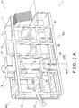
- FIG. 2A is a perspective view showing the configuration of the box packing system 1
- FIG. 2B is a perspective view showing a flow of cardboard boxes B and products G in the box packing system 1.
- the box packing system 1 packs a predetermined number of bagged products (products G), such as snack foods for example, in an aligned state and in multiple layers into cardboard boxes B.
- the box packing system 1 comprises a cardboard box handling area DHA and a product handling area GHA that are interconnected in a state in which they are mutually independently separable.
- the cardboard box handling area DHA includes two processes, a case forming process P1 and a box packing process P3.
- the product handling area GHA includes a product aligning process P2.
- the three processes of the case forming process PI, the product aligning process P2, and the box packing process P3 work together because the cardboard box handling area DHA and the product handling area GHA are interconnected.
- the case forming process P1 is a process of erecting sheet-like cardboard box precursors Z into cardboard boxes B and conveying the cardboard boxes B to a box packing position.
- the case forming process P1 is configured by a box precursor accommodating unit 11, a case forming unit 12, a first posture converting unit 13, and a box downward conveying unit 14.
- the product aligning process P2 is a process of feeding to a predetermined position the products G that are supplied from an upstream process, aligning a predetermined number of the products G so that adjacent products G partially lie on top of each other, and conveying the predetermined number of products G to the box packing position.
- the product aligning process P2 is configured by a product feeding unit 21, a product aligning unit 22, and a product inserting unit 23.
- the box packing process P3 is a process of packing, into the cardboard boxes B that have been conveyed thereto from the case forming process PI, the predetermined quantity of the products G that have finished being aligned in the product aligning process P2, closing the boxes, and conveying the boxes to a box discharge position.
- the box packing process P3 is configured by a product receiving unit 31, a second posture converting unit 32, and a case sealing unit 33.
- the box packing system 1 performs multilayer packing of the products G into the cardboard boxes B, and the posture of the products G inside the cardboard boxes B is a "standing posture.” That is, the standing posture is a posture where, when the openings of the cardboard boxes B face up, the front sides and the back surfaces of the products G face sideways, the upper and lower end portions of the products G face up and down, and the left and right side portions of the products G face sideways.
- the cardboard box handling area DHA has a two-level structure, and the case forming process P1 and the box packing process P3 are supported by a common frame 10.
- the case forming process P1 occupies the second-level portion, and the box packing process P3 occupies the first-level portion.
- the conveyance direction of the cardboard boxes B from the erection of the cardboard boxes B by the case forming unit 12 to the box downward conveying unit 14 and the conveyance direction of the cardboard boxes B up to when the openings of the cardboard boxes B that have been packed with the products G are sealed by the case sealing unit 33 are mutually opposite directions.
- the case forming process P1 is configured by the box precursor accommodating unit 11 that introduces the cardboard box precursors Z to the box packing system 1, the case forming unit 12 that erects the cardboard boxes B, the first posture converting unit 13 that rotates the cardboard boxes B 90° about a horizontal axis orthogonal to the conveyance direction, and the box downward conveying unit 14 that conveys downward the cardboard boxes B that have been converted to a first posture.
- the box precursor accommodating unit 11 picks one at a time and transports upward the cardboard box precursor Z at the very front of the cardboard box precursors Z stacked in a supply position and rotates the transported cardboard box precursor Z 90° about a vertical axis to thereby open it into a tubular shape.
- the cardboard box precursors Z are placed in the supply position by a worker.
- the cardboard box precursors Z are collapsed with their flaps Zf open and are stacked in a horizontal direction in a posture in which the flaps Zf are positioned in the vertical direction.
- the flaps Zf on the top surface side will be called top flaps Zfa and the flaps Zf on the bottom surface side will be called bottom flaps Zfb.
- the upward transport of the cardboard box precursors Z is performed by a lift mechanism 111.
- a detection sensor (not shown in the drawings) sends a detection signal to a controller 40 (see FIG. 1 ).
- the rotation of the cardboard box precursors Z about the vertical axis is realized by sucking and holding, with suction cups, the side surfaces of the cardboard box precursors Z with a sucking and rotating mechanism 112 and rotating the sucking and rotating mechanism 112 90° about the vertical axis.
- the case forming unit 12 conveys in a horizontal direction the cardboard box precursors Z that have been opened into a tubular shape and at the same time folds the bottom flaps Zfb of the cardboard box precursors Z to form bottoms, thereby erecting the cardboard boxes B which are in a state in which their top flaps Zfa are open.
- the case forming unit 12 configures the cardboard box erector pertaining to this invention, and its details are described in "(5) Details of Case Forming Unit 12" below.
- the first posture converting unit 13 rotates the cardboard boxes B 90° in the conveyance direction. More specifically, the first posture converting unit 13 rotates the cardboard boxes B 90° about a horizontal axis orthogonal to the conveyance direction to thereby convert the posture of the cardboard boxes B to a posture (hereinafter called a first posture) in which the openings and the top flaps Zfa of the cardboard boxes B lie in the same vertical plane.
- a posture hereinafter called a first posture
- the box downward conveying unit 14 conveys downward the cardboard boxes B that have been converted to the first posture. That is, the box downward conveying unit 14 moves the cardboard boxes B downward with the openings of the cardboard boxes B kept facing the product handling area GHA.
- a weigher and a bag-making and packaging machine and the like Disposed upstream of the product aligning process P2 in the flow of the products G in the box packing system 1 are a weigher and a bag-making and packaging machine and the like not shown in the drawings. Only products G that have passed weight, seal, and contamination inspections and the like in the upstream process are supplied to the product aligning process P2 in the box packing system 1.
- the product aligning process P2 is configured by the product feeding unit 21 that receives the products G and conveys them to a predetermined position, the product aligning unit 22 that aligns the products G that are supplied from the product feeding unit 21, and the product inserting unit 23 that accumulates and pushes out the aligned products G.
- the product feeding unit 21 has a product introducing conveyor 211 and a feeding conveyor 212.
- the product introducing conveyor 211 receives, in a downstream of the process that performs the weight, seal, and contamination inspections and the like, the supply of the products G that have passed the inspections and leads those products G to the feeding conveyor 212.
- the feeding conveyor 212 conveys to the product aligning unit 22 the products G conveyed thereto from the product introducing conveyor 211.
- the product aligning unit 22 has a first aligning conveyor 221, a second aligning conveyor 222, and a third aligning conveyor 223.
- the product aligning unit 22 conveys the products G to a predetermined position while performing an accumulating action with respect to the products G.
- the product aligning unit 22 is particularly suited for accumulating bag-like packages, so it can also be used independently as a package accumulating device.
- the product inserting unit 23 sandwiches the front and rear of the group of products G that have been aligned in a line by the third aligning conveyor 223 and inserts the whole group of products G into the cardboard boxes B. As shown in FIG. 2B , the product inserting unit 23 has a stand-up conveyor 231, a push plate 233, and an insertion plate 235 in order to sandwich the aligned group of products G.
- the box packing process P3 has the product receiving unit 31 that receives the products G into the cardboard boxes B, the second posture converting unit 32 that converts the posture of the cardboard boxes B so that the openings of the cardboard boxes B face up, and the case sealing unit 33 that conveys the cardboard boxes B that have finished being packed with the products G and at the same time closes the openings of the cardboard boxes B.
- the product receiving unit 31 maintains the cardboard boxes B in the first posture and has the cardboard boxes B stand by with their openings opposing the insertion plate 235 of the product inserting unit 23.
- An N-number of the products G that have been converted to the standing state in the product inserting unit 23 are pushed out by the insertion plate 235 toward the open surfaces of the cardboard boxes B, so the product receiving unit 31 stands by in that position until the N-number of the products G are completely inserted through the openings to the bottoms of the cardboard boxes B.
- the product receiving unit 31 descends a predetermined distance. Then, in order to receive a second layer of the N-number of the products G, the product receiving unit 31 has the cardboard box B stand by in such a way that the portion of the opening of the cardboard box B that leads to the space above the first layer opposes the insertion plate 235.
- the product receiving unit 31 repeats the above actions so that an i-th layer of the N-number of the products G is inserted into the cardboard box B, and then the receiving of the products G into the cardboard box B is finished.
- the second posture converting unit 32 has a posture converting mechanism 321 that converts the posture of the cardboard boxes B packed with the products G to a posture in which the openings face up.
- the posture converting mechanism 321 rotates the cardboard boxes B so that the open surfaces that had been vertical until then become horizontal, namely, so that the open surfaces face up.
- the posture converting mechanism 321 holds the cardboard boxes B with an L-shaped member having suction cups that simultaneously suck the side surfaces and the bottom surfaces of the cardboard boxes B, and when the L-shaped member rotates 90°, the cardboard boxes B rotate.
- the case sealing unit 33 has a discharge conveyor 330 that conveys the cardboard boxes B, a flap closing mechanism (not shown in the drawings) that closes the flaps surrounding the openings of the cardboard boxes B, and a tape applicator 380 that seals the openings that have been closed by the flaps.
- FIG. 3A is a perspective view of the cardboard box precursor Z that has been opened into a tubular shape before the bottom flaps Zfb are folded.
- FIG. 3B is a perspective view showing, in three stages, the process of folding the bottom flaps Zfb shown in FIG. 3A .
- the bottom flaps Zfb include a pair of large flaps Zfb1, Zfb3 that are opposite each other and a pair of small flaps Zfb2, Zfb4 that are opposite each other.
- One large flap Zfb1 out of the pair of large flaps Zfb1, Zfb3 is provided with a recessed cutout Zfb1a, and the other large flap Zfb3 is provided with a tongue-like projecting piece Zfb3a.
- the large flap Zfb1 having the recessed cutout Zfb1a will be called a preceding large flap Zfb1
- the large flap Zfb3 having the tongue-like projecting piece Zfb3a will be called a locking large flap Zfb3.
- FIG. 3B is a perspective view showing the folding order of the bottom flaps Zfb in a cardboard box B whose bottom flaps Zfb are facing up.
- first the preceding large flap Zfb1 is folded, then the pair of small flaps Zfb2, Zfb4 are folded, and lastly the locking large flap Zfb3 is folded.
- the locking large flap Zfb3 is pushed inside the cardboard box B so that the tongue-like projecting piece Zfb3a goes past the recessed cutout Zfb1a of the preceding large flap Zfb1, contacts the inside surface of the preceding large flap Zfb1, and stops. Because of this, the four bottom flaps Zfb interfere with each other and become locked.
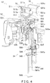
- FIG. 4 is a perspective view of main portions of the case forming unit 12.
- the case forming unit 12 functioning as the cardboard box erector includes a first folding mechanism 51, a second folding mechanism 52, a third folding mechanism 53, a pushing mechanism 54, and a suction mechanism 55.
- the first folding mechanism 51 is a mechanism that folds the preceding large flap Zfb1 and includes a first folding plate 511, a first coupling bar 513, and a first air cylinder 515.
- FIG. 4 the positional relationship between the first air cylinder 515 and the first folding plate 511 and first coupling bar 513 cannot be seen, so reference is to be made to FIG. 11 , which shows a general side view of the first folding mechanism 51.
- the first folding plate 511 is a plate metal member having a first surface 511a, a second surface 511b, and a third surface 511c.
- the second surface 511b extends so as to form an obtuse angle with respect to the first surface 511a from the end of the first surface 511a.
- the third surface 511c extends perpendicularly with respect to the first surface 511a from the end of the second surface 511b. Therefore, when the first surface 511a is horizontal, the third surface 511c is in a vertical posture, and when the first surface 511a is vertical, the third surface 511c is horizontal.
- the first coupling bar 513 is a bar that transmits the displacement of a piston of the first air cylinder 515 to the first folding plate 511.
- One end of the first coupling bar 513 is secured to the back surface of the first surface 511a of the first folding plate 511.
- the back surface of the first surface 511a is the surface on the opposite side of the surface that contacts the preceding large flap Zfb1 when folding the preceding large flap Zfb1.
- the other end of the first coupling bar 513 is coupled to the distal end of a piston 515a of the first air cylinder 515.
- a rotational shaft 519 supported by a bearing 517 is coupled to part of the first coupling bar 513. Therefore, when the piston 515a reciprocates, the first coupling bar 513 pivots about the rotational shaft 519, so the first folding plate 511 swings in accompaniment therewith.
- the second folding mechanism 52 includes a pair of second folding plates 521 that are opposite each other and second air cylinders 525 that cause the pair of second folding plates 521 to pivot.
- the second folding plate 521 on the side that folds the small flap Zfb2 will be called a second folding plate 521A
- the second folding plate 521 on the side that folds the small flap Zfb4 will be called a second folding plate 521B (see FIG. 7 and FIG. 8 ).
- the air cylinder that causes the second folding plate 521A to pivot will be called a second air cylinder 525A
- the air cylinder that causes the second folding plate 521B to pivot will be called a second air cylinder 525B.
- the second folding plate 521A is a plate metal member having a quarter arc.
- a pivot shaft is provided in a position a predetermined distance away from the quarter arc.
- the distal end of a piston of the second air cylinder 525A is coupled between the quarter arc and the pivot shaft.
- the second folding plate 521B is also a plate metal member having a quarter arc.
- the second folding plate 521B has the same shape as a mirror image of the second folding plate 521A, and a pivot shaft is provided in a position a predetermined distance away from the quarter arc.
- the distal end of a piston of the second air cylinder 525B is coupled between the quarter arc and the pivot shaft.
- the third folding mechanism 53 is a mechanism that folds the locking large flap Zfb3 and includes a third folding plate 531, a third coupling bar 533, and a third air cylinder 535.
- FIG. 4 the positional relationship between the third air cylinder 535 and the third folding plate 531 and third coupling bar 533 cannot be seen, so reference is to be made to FIG. 11 , which shows a general side view of the third folding mechanism 53.
- the third folding plate 531 is a plate metal member having a first surface 531a, a second surface 531b, and a third surface 531c.
- the second surface 531b extends so as to form an obtuse angle with respect to the first surface 531a from the end of the first surface 531a.
- the third surface 531c extends perpendicularly with respect to the first surface 531a from the end of the second surface 531b. Therefore, when the first surface 531a is horizontal, the third surface 531c is in a vertical posture, and when the first surface 531a is vertical, the third surface 531c is horizontal.
- the third coupling bar 533 is a bar that transmits the displacement of a piston of the third air cylinder 535 to the third folding plate 531.
- One end of the third coupling bar 533 is secured to the back surface of the first surface 531a of the third folding plate 531.
- the back surface of the first surface 531a is the surface on the opposite side of the surface that contacts the locking large flap Zfb3 when folding the locking large flap Zfb3.
- the other end of the third coupling bar 533 is coupled to the distal end of a piston 535a of the third air cylinder 535.
- a rotational shaft 539 supported by a bearing 537 is coupled to part of the third coupling bar 533. Therefore, when the piston 535a reciprocates, the third coupling bar 533 pivots about the rotational shaft 539, so the third folding plate 531 swings in accompaniment therewith.
- the third coupling bar 533 in this embodiment is configured by two bar members, and the two bar members are coupled to each other via the rotational shaft 539.
- the locking large flap Zfb3 is pushed inside the cardboard box B so that the tongue-like projecting piece Zfb3a goes past the recessed cutout Zfb1a of the preceding large flap Zfb1, contacts the inside surface of the preceding large flap Zfb1, and stops.
- the pushing mechanism 54 has pushing rods 541 that push the locking large flap Zfb3 inside the cardboard box B.
- the pushing rods 541 comprise two pushing rods 541a, 541b.
- the two pushing rods 541a, 541b are supported by an upper retention plate 543, a guide plate 544, a middle retention plate 545, and a lower retention plate 546 to maintain an equal distance between themselves.
- the above four plate members are disposed in the order of the upper retention plate 543, the guide plate 544, the middle retention plate 545, and the lower retention plate 546 from above.
- Two through holes through which the two pushing rods 541a, 541b pass are provided in each of the upper retention plate 543, the guide plate 544, the middle retention plate 545, and the lower retention plate 546.
- the two pushing rods 541a, 541b can maintain an equal distance between themselves.
- the two pushing rods 541a, 541b are secured to the two through holes in each of the upper retention plate 543, the middle retention plate 545, and the lower retention plate 546.
- the two pushing rods 541a, 541b are relatively movable with respect to the two through holes in the guide plate 544 as a result of enough clearance to allow the two pushing rods 541a, 541b to slide therein being provided.
- a head 541c that directly contacts the locking large flap Zfb3 is supported by the distal ends of the pushing rods 541.
- the head 541c is a plate metal member formed by bending from one metal piece.
- the cross section of the head 541c is L-shaped.
- a pushing first air cylinder 547 is disposed in a posture in which its piston 547a faces vertically downward.
- the distal end portion of the piston 547a is coupled to the middle retention plate 545.
- a pushing second air cylinder 549 is disposed in a posture in which its piston 549a faces vertically upward.
- the distal end portion of the piston 549a is coupled to the head 541c.
- Two second pushing rods (not shown in the drawings) with the same pitch as the two pushing rods 541a, 541b are coupled to the undersurface of the head 541c.
- the two pushing rods 541a, 541b are hollow cylinders, and the two second pushing rods have an outer diameter that is slightly smaller than the inner diameter of the hollow cylinders.
- One of the second pushing rods is inserted inside the hollow cylinder of the pushing rod 541a, and the other of the second pushing rods is inserted inside the hollow cylinder of the pushing rod 541b.
- the suction mechanism 55 is provided on the upper surface of the head 541c of the pushing rods 541.
- the suction mechanism 55 has at least a suction cup 551.
- the suction cup 551 sucks hold of the outer surface of the locking large flap Zfb3 when the locking large flap Zfb3 has been pushed inside the cardboard box B, and in the process of the head 541c returning to a standby position, the suction cup 551 pulls back the locking large flap Zfb3 from the position to which the locking large flap Zfb3 had been pushed to a position even with the bottom surface of the cardboard box B.
- FIG. 5 is a side view of the suction cup 551 just before the suction cup 551 contacts the locking large flap Zfb3.
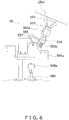
- FIG. 6 is a side view of the suction cup 551 when the suction cup 551 has contacted the locking large flap Zfb3 and pushed in the locking large flap Zfb3.
- the suction mechanism 55 includes the suction cup 551, a connector 553, a connector retention plate 555, and a posture control spring 557.
- the suction cup 551 is a bellows-shaped member formed of silicon rubber, for example.
- the connector 553 is connected to the suction cup 551 on the opposite side of the suction surface of the suction cup 551.
- the body portion of the connector 553 is hollow, and a connection hole 553a to which a suction tube (not shown in the drawings) is connected is provided in the side surface of the body portion of the connector 553.
- the connector 553 is provided with a bolt 553b that is a threaded part.
- the connector 553 is secured to the connector retention plate 555 by the bolt 553b and a nut 554.
- the connector retention plate 555 is rotatably retained by the head 541c.
- the posture control spring 557 is a torsion coil spring, with one end thereof being caught in the connector retention plate 555 and the other end thereof being caught in the head 541c.
- the suction cup 551 adopts a posture in which its suction surface faces vertically upward when it stands by.
- the suction surface of the suction cup 551 inclines to match the change in the angle of inclination of the locking large flap Zfb3.
- the angular displacement of the suction surface of the suction cup 551 is transmitted to the connector retention plate 555 via the connector 553, and the connector retention plate 555 becomes angularly displaced counter to the biasing force of the posture control spring 557.
- FIG. 7 is a side view of the cardboard box B after the preceding large flap Zfb1 has been folded and just before the small flaps Zfb2, Zfb4 are folded.
- FIG. 8 is a side view of the cardboard box B after the small flaps Zfb2, Zfb4 have been folded.
- the first folding plate 511 has already folded the preceding large flap Zfb1 and is standing by. At this time, the set of small flaps Zfb2, Zfb4 are waiting to be folded by the second folding plates 521A, 521B.
- FIG. 9 is a front view of the cardboard box B when the third folding plate 531 has folded the locking large flap Zfb3 and the head 541c has ascended.
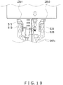
- FIG. 10 is a front view of the cardboard box B when the head 541c has descended.
- the locking large flap Zfb3 is pushed until the projecting piece Zfb3a of the locking large flap Zfb3 goes past the cutout Zfb1a of the preceding large flap Zfb1 and rides up onto the inside surface of the preceding large flap Zfb1.
- the suction surface of the suction cup 551 inclines to match the change in the angle of inclination of the locking large flap Zfb3.
- the angular displacement of the suction surface of the suction cup 551 is transmitted via the connector 553 to the connector retention plate 555, and the connector retention plate 555 becomes angularly displaced counter to the biasing force of the posture control spring 557.
- FIG. 10 is a front view of the cardboard box B when the head 541c has descended and the locking large flap Zfb3 has been returned to the original level of the bottom surface.
- the suction cup 551 in accompaniment with the descent of the head 541c, the suction cup 551 also descends.
- the suction cup 551 descends in a state in which it is sucking hold of the outer surface of the locking large flap Zfb3, so the locking large flap Zfb3 is pulled back to the height position of the bottom surface of the cardboard box B without staying inside the cardboard box B.
- the projecting piece Zfb3a of the locking large flap Zfb3 goes past the cutout Zfb1a of the preceding large flap Zfb1 and rides up onto the inside surface of the preceding large flap Zfb1 at the stage before the locking large flap Zfb3 is pulled back to the height position of the bottom surface of the cardboard box B, and the locking large flap Zfb3 descends so as to press down the preceding large flap Zfb1, so they descend to the height position of the bottom surface in the order of the preceding large flap Zfb1 and the locking large flap Zfb3.
- the connector retention plate 555 is biased by the posture control spring 557, so it can follow the change in the angle of inclination of the suction surface of the suction cup 551.
- the suction surface of the suction cup 551 can follow the change in the angle of inclination of the locking large flap Zfb3 and can maintain reliable suction.
- the suction by the suction cup 551 is cancelled at the timing when the suction surface of the suction cup 551 reaches the height position of the bottom surface of the cardboard box B, and the head 541c descends further and the suction cup 551 separates from the locking large flap Zfb3.
- the head 541c performs an action wherein it pushes, deep inside the cardboard box B, the locking large flap Zfb3 folded last out of the four flaps and goes back.
- the suction cup 551 that moves in conjunction with the head 541c sucks and holds the locking large flap Zfb3, so when the head 541c goes back, the suction cup 551 can pull back the locking large flap Zfb3 to the bottom (the open surface).
- the pushing mechanism 54 is secured to part of the third folding mechanism 53 that folds the locking large flap Zfb3. As a result, it suffices for the pushing mechanism 54 to start the pushing action from a predetermined position of the third folding mechanism that is in a position near the locking large flap Zfb3, so the push stroke can be shortened.
- the locking large flap Zfb3 that is pushed pivots about its base (the edge of the opening) as a central axis, so its posture changes in such a way that its angle of inclination increases in accordance with the distance it is pushed, but the suction cup 551 is pivotably retained by the head 541c, and the suction surface of the suction cup 551 follows the change in the angle of inclination of the locking large flap Zfb3, so the suction cup 551 can maintain stable suction even when the locking large flap Zfb3 inclines.
- Types of forming the bottom of the cardboard box B include the locking bottom type such as in this application and the conventional taped type. Realizing a case forming unit that can be used for both is ideal, but the order in which the bottom flaps are folded and the lengths of the bottom flaps are different, so it is necessary to prevent interference between the bottom flaps and the folding mechanisms through changing the arrangement of the folding mechanisms and adjusting the folding timings.
- the locking bottom type such as in this application needs to have the locking large flap pushed in last and needs to be configured to not interfere with the pushing mechanism when the sheet-like cardboard box precursor is opened and conveyed to the folding mechanisms.
- the bottom flaps of the cardboard box support each other, so after forming the bottom, a mechanism that supports the bottom when conveying the cardboard box is unnecessary, but with a taped type, it is necessary to support the bottom, so it is necessary to convey the cardboard box to the taping region in a state in which the folding mechanisms support the bottom.
- the first folding plate 511, the second folding plates 521A, 521B, and the third folding plate 531 have structures and arrangements that do not interfere with each other even while they retain the corresponding bottom flaps Zfb.
Landscapes
- Engineering & Computer Science (AREA)
- Mechanical Engineering (AREA)
- Supplying Of Containers To The Packaging Station (AREA)
- Making Paper Articles (AREA)
- Closing Of Containers (AREA)
- Container Filling Or Packaging Operations (AREA)
Abstract
Description
- This application claims priority to Japanese Patent Application No.
2019-23643, filed February 13, 2019 - The present invention relates to a cardboard box erector.
- In recent years, cardboard boxes with easily erectable bottoms have become common, and devices that erect such cardboard boxes have become widespread. For example, patent document 1 (
JP-A No. 2012-162271 - However, because the second bottom flap is pushed inside the packaging box to allow the tongue portion to engage with the top of the engagement receiving portion of the first bottom flap, in a case where the second bottom flap stays inside and does not come back, the work of flipping over the packaging box and pushing back the second bottom flap from inside becomes necessary.
- It is an object of the present invention to provide a cardboard box erector that reduces a situation where a bottom flap it has pushed in last does not come back.
- A cardboard box erector pertaining to a first aspect of the invention is a cardboard box erector that folds four flaps provided on edges of an opening of a cardboard box so as to surround the opening, the cardboard box erector having a folding unit and a pushing unit. The four flaps include a locking flap folded last among the four flaps. The folding unit folds each of the four flaps in a predetermined order to close the opening. The pushing unit performs an action to push the locking flap inside the cardboard box and pull the locking flap back. The pushing unit has a suction unit that sucks and holds the locking flap.
- In this cardboard box erector, the locking flap is pushed deep inside past the open surface of the opening, but the suction unit that moves in conjunction with the pushing unit sucks and holds the locking flap, so when the pushing unit goes back, the suction unit can pull back the locking flap to the open surface.
- A cardboard box erector pertaining to a second aspect of the invention is the cardboard box erector pertaining to the first aspect, wherein the pushing unit is secured to part of the folding unit.
- In this cardboard box erector, it suffices for the pushing unit to start the pushing action from a predetermined position of the folding unit that is in a position near the locking flap, so the push stroke can be shortened.
- A cardboard box erector pertaining to a third aspect of the invention is the cardboard box erector pertaining to the second aspect, wherein the four flaps include a set of small flaps that are opposite each other and a set of large flaps that are opposite each other, with one of the set of large flaps being the locking flap. The folding unit has a first folding unit, a second folding unit, and a third folding unit. The first folding unit folds the large flap that is opposite the locking flap out of the set of large flaps. The second folding unit folds the set of small flaps. The third folding unit folds the locking flap out of the set of large flaps. The pushing unit is secured to the third folding unit.
- In this cardboard box erector, it suffices for the pushing unit to start the pushing action from a predetermined position of the third folding unit that folds the locking flap, so the push stroke can be shortened.
- A cardboard box erector pertaining to a fourth aspect of the invention is the cardboard box erector pertaining to any one of the first aspect to the third aspect, wherein the suction unit allows the posture of its suction surface that sucks the locking flap to follow changes in the posture of the locking flap.
- In this cardboard box erector, the locking flap that is pushed pivots about the edge of the opening as a central axis, so its posture changes in such a way that its angle of inclination increases in accordance with the distance it is pushed. The suction surface of the suction unit follows that change in posture, so it can maintain stable suction even when the locking flap inclines.
- A cardboard box erector pertaining to a fifth aspect of the invention is the cardboard box erector pertaining to the fourth aspect, wherein the suction unit is pivotably retained by the pushing unit.
- In this cardboard box erector, even when the locking flap is pushed and its angle of inclination increases, the suction surface follows the angle of inclination of the locking flap as a result of the suction unit pivoting.
- In the cardboard box erector pertaining to the present invention, the locking flap is pushed deep inside past the open surface of the opening, but the suction unit that moves in conjunction with the pushing unit sucks and holds the locking flap, so when the pushing unit goes back, the suction unit can pull back the locking flap to the open surface.
-
-
FIG. 1 is a block diagram of a box packing system equipped with a cardboard box erector pertaining to an embodiment of the invention. -
FIG. 2A is a perspective view showing the configuration of the box packing system. -
FIG. 2B is a perspective view showing a flow of cardboard boxes and products in the box packing system. -
FIG. 3A is a perspective view of a cardboard box precursor that has been opened into a tubular shape before bottom flaps are folded. -
FIG. 3B is a perspective view showing, in three stages, a process of folding the bottom flaps shown inFIG. 3A . -
FIG. 4 is a perspective view of main portions of a case forming unit. -
FIG. 5 is a side view of a suction cup just before the suction cup contacts a locking large flap. -
FIG. 6 is a side view of the suction cup when the suction cup has contacted the locking large flap and pushed in the locking large flap. -
FIG. 7 is a side view of a cardboard box B after a preceding large flap has been folded and just before small flaps are folded. -
FIG. 8 is a side view of the cardboard box B after the small flaps have been folded. -
FIG. 9 is a front view of the cardboard box B when a third folding plate has folded the locking large flap and a head has ascended. -
FIG. 10 is a front view of the cardboard box when the head has descended. -
FIG. 11 is a general side view of a first folding mechanism and a third folding mechanism. - An embodiment of the invention will be described below with reference to the drawings. The following embodiment is a specific example of the invention and is not intended to limit the technical scope of the invention.
-
FIG. 1 is a block diagram of abox packing system 1 equipped with a cardboard box erector pertaining to an embodiment of the invention.FIG. 2A is a perspective view showing the configuration of thebox packing system 1, andFIG. 2B is a perspective view showing a flow of cardboard boxes B and products G in thebox packing system 1. - In
FIG. 1 andFIG. 2A , thebox packing system 1 packs a predetermined number of bagged products (products G), such as snack foods for example, in an aligned state and in multiple layers into cardboard boxes B. - As shown in
FIG. 1 andFIG. 2A , thebox packing system 1 comprises a cardboard box handling area DHA and a product handling area GHA that are interconnected in a state in which they are mutually independently separable. The cardboard box handling area DHA includes two processes, a case forming process P1 and a box packing process P3. The product handling area GHA includes a product aligning process P2. - That is, in the
box packing system 1, the three processes of the case forming process PI, the product aligning process P2, and the box packing process P3 work together because the cardboard box handling area DHA and the product handling area GHA are interconnected. - The case forming process P1 is a process of erecting sheet-like cardboard box precursors Z into cardboard boxes B and conveying the cardboard boxes B to a box packing position. The case forming process P1 is configured by a box
precursor accommodating unit 11, acase forming unit 12, a firstposture converting unit 13, and a box downward conveyingunit 14. - The product aligning process P2 is a process of feeding to a predetermined position the products G that are supplied from an upstream process, aligning a predetermined number of the products G so that adjacent products G partially lie on top of each other, and conveying the predetermined number of products G to the box packing position. The product aligning process P2 is configured by a
product feeding unit 21, aproduct aligning unit 22, and aproduct inserting unit 23. - The box packing process P3 is a process of packing, into the cardboard boxes B that have been conveyed thereto from the case forming process PI, the predetermined quantity of the products G that have finished being aligned in the product aligning process P2, closing the boxes, and conveying the boxes to a box discharge position. The box packing process P3 is configured by a
product receiving unit 31, a secondposture converting unit 32, and acase sealing unit 33. - The
box packing system 1 performs multilayer packing of the products G into the cardboard boxes B, and the posture of the products G inside the cardboard boxes B is a "standing posture." That is, the standing posture is a posture where, when the openings of the cardboard boxes B face up, the front sides and the back surfaces of the products G face sideways, the upper and lower end portions of the products G face up and down, and the left and right side portions of the products G face sideways. - As shown in
FIG. 2A andFIG. 2B , the cardboard box handling area DHA has a two-level structure, and the case forming process P1 and the box packing process P3 are supported by acommon frame 10. The case forming process P1 occupies the second-level portion, and the box packing process P3 occupies the first-level portion. - In order to realize this two-level structure, the conveyance direction of the cardboard boxes B from the erection of the cardboard boxes B by the
case forming unit 12 to the box downward conveyingunit 14 and the conveyance direction of the cardboard boxes B up to when the openings of the cardboard boxes B that have been packed with the products G are sealed by thecase sealing unit 33 are mutually opposite directions. - As shown in
FIG. 2B , the case forming process P1 is configured by the boxprecursor accommodating unit 11 that introduces the cardboard box precursors Z to thebox packing system 1, thecase forming unit 12 that erects the cardboard boxes B, the firstposture converting unit 13 that rotates the cardboard boxes B 90° about a horizontal axis orthogonal to the conveyance direction, and the box downward conveyingunit 14 that conveys downward the cardboard boxes B that have been converted to a first posture. - The box
precursor accommodating unit 11, as shown inFIG. 2B , picks one at a time and transports upward the cardboard box precursor Z at the very front of the cardboard box precursors Z stacked in a supply position and rotates the transported cardboard box precursor Z 90° about a vertical axis to thereby open it into a tubular shape. - The cardboard box precursors Z are placed in the supply position by a worker. The cardboard box precursors Z are collapsed with their flaps Zf open and are stacked in a horizontal direction in a posture in which the flaps Zf are positioned in the vertical direction. For convenience of description, the flaps Zf on the top surface side will be called top flaps Zfa and the flaps Zf on the bottom surface side will be called bottom flaps Zfb.
- The upward transport of the cardboard box precursors Z is performed by a
lift mechanism 111. When all the cardboard box precursors Z in the supply position run out, a detection sensor (not shown in the drawings) sends a detection signal to a controller 40 (seeFIG. 1 ). - The rotation of the cardboard box precursors Z about the vertical axis is realized by sucking and holding, with suction cups, the side surfaces of the cardboard box precursors Z with a sucking and
rotating mechanism 112 and rotating the sucking androtating mechanism 112 90° about the vertical axis. - The
case forming unit 12 conveys in a horizontal direction the cardboard box precursors Z that have been opened into a tubular shape and at the same time folds the bottom flaps Zfb of the cardboard box precursors Z to form bottoms, thereby erecting the cardboard boxes B which are in a state in which their top flaps Zfa are open. - The
case forming unit 12 configures the cardboard box erector pertaining to this invention, and its details are described in "(5) Details ofCase Forming Unit 12" below. - The first
posture converting unit 13 rotates the cardboard boxes B 90° in the conveyance direction. More specifically, the firstposture converting unit 13 rotates the cardboard boxes B 90° about a horizontal axis orthogonal to the conveyance direction to thereby convert the posture of the cardboard boxes B to a posture (hereinafter called a first posture) in which the openings and the top flaps Zfa of the cardboard boxes B lie in the same vertical plane. When the cardboard boxes B are in the first posture, their openings face the product handling area GHA. - The box downward conveying
unit 14 conveys downward the cardboard boxes B that have been converted to the first posture. That is, the box downward conveyingunit 14 moves the cardboard boxes B downward with the openings of the cardboard boxes B kept facing the product handling area GHA. - Disposed upstream of the product aligning process P2 in the flow of the products G in the
box packing system 1 are a weigher and a bag-making and packaging machine and the like not shown in the drawings. Only products G that have passed weight, seal, and contamination inspections and the like in the upstream process are supplied to the product aligning process P2 in thebox packing system 1. - The product aligning process P2 is configured by the
product feeding unit 21 that receives the products G and conveys them to a predetermined position, theproduct aligning unit 22 that aligns the products G that are supplied from theproduct feeding unit 21, and theproduct inserting unit 23 that accumulates and pushes out the aligned products G. - The
product feeding unit 21 has aproduct introducing conveyor 211 and afeeding conveyor 212. Theproduct introducing conveyor 211 receives, in a downstream of the process that performs the weight, seal, and contamination inspections and the like, the supply of the products G that have passed the inspections and leads those products G to thefeeding conveyor 212. - The feeding
conveyor 212 conveys to theproduct aligning unit 22 the products G conveyed thereto from theproduct introducing conveyor 211. - The
product aligning unit 22 has a first aligningconveyor 221, a second aligningconveyor 222, and a third aligningconveyor 223. Theproduct aligning unit 22 conveys the products G to a predetermined position while performing an accumulating action with respect to the products G. Theproduct aligning unit 22 is particularly suited for accumulating bag-like packages, so it can also be used independently as a package accumulating device. - The
product inserting unit 23 sandwiches the front and rear of the group of products G that have been aligned in a line by the third aligningconveyor 223 and inserts the whole group of products G into the cardboard boxes B. As shown inFIG. 2B , theproduct inserting unit 23 has a stand-upconveyor 231, apush plate 233, and aninsertion plate 235 in order to sandwich the aligned group of products G. - The box packing process P3 has the
product receiving unit 31 that receives the products G into the cardboard boxes B, the secondposture converting unit 32 that converts the posture of the cardboard boxes B so that the openings of the cardboard boxes B face up, and thecase sealing unit 33 that conveys the cardboard boxes B that have finished being packed with the products G and at the same time closes the openings of the cardboard boxes B. - The
product receiving unit 31 maintains the cardboard boxes B in the first posture and has the cardboard boxes B stand by with their openings opposing theinsertion plate 235 of theproduct inserting unit 23. An N-number of the products G that have been converted to the standing state in theproduct inserting unit 23 are pushed out by theinsertion plate 235 toward the open surfaces of the cardboard boxes B, so theproduct receiving unit 31 stands by in that position until the N-number of the products G are completely inserted through the openings to the bottoms of the cardboard boxes B. - When a first layer of the N-number of the products G is inserted into a cardboard box B, the
product receiving unit 31 descends a predetermined distance. Then, in order to receive a second layer of the N-number of the products G, theproduct receiving unit 31 has the cardboard box B stand by in such a way that the portion of the opening of the cardboard box B that leads to the space above the first layer opposes theinsertion plate 235. - The
product receiving unit 31 repeats the above actions so that an i-th layer of the N-number of the products G is inserted into the cardboard box B, and then the receiving of the products G into the cardboard box B is finished. - As shown in
FIG. 2B , the secondposture converting unit 32 has aposture converting mechanism 321 that converts the posture of the cardboard boxes B packed with the products G to a posture in which the openings face up. - The
posture converting mechanism 321 rotates the cardboard boxes B so that the open surfaces that had been vertical until then become horizontal, namely, so that the open surfaces face up. Theposture converting mechanism 321 holds the cardboard boxes B with an L-shaped member having suction cups that simultaneously suck the side surfaces and the bottom surfaces of the cardboard boxes B, and when the L-shaped member rotates 90°, the cardboard boxes B rotate. - As shown in
FIG. 2B , thecase sealing unit 33 has adischarge conveyor 330 that conveys the cardboard boxes B, a flap closing mechanism (not shown in the drawings) that closes the flaps surrounding the openings of the cardboard boxes B, and atape applicator 380 that seals the openings that have been closed by the flaps. - Here, the actions of folding the bottom flaps Zfb of the cardboard box precursor Z that has been opened into a tubular shape will be mainly described.
- First, before these actions are described, the cardboard box B handled by the
box packing system 1 will be described.FIG. 3A is a perspective view of the cardboard box precursor Z that has been opened into a tubular shape before the bottom flaps Zfb are folded.FIG. 3B is a perspective view showing, in three stages, the process of folding the bottom flaps Zfb shown inFIG. 3A . - In
FIG. 3A and FIG. 3B , the bottom flaps Zfb include a pair of large flaps Zfb1, Zfb3 that are opposite each other and a pair of small flaps Zfb2, Zfb4 that are opposite each other. - One large flap Zfb1 out of the pair of large flaps Zfb1, Zfb3 is provided with a recessed cutout Zfb1a, and the other large flap Zfb3 is provided with a tongue-like projecting piece Zfb3a. For convenience of description, the large flap Zfb1 having the recessed cutout Zfb1a will be called a preceding large flap Zfb1, and the large flap Zfb3 having the tongue-like projecting piece Zfb3a will be called a locking large flap Zfb3.
-
FIG. 3B is a perspective view showing the folding order of the bottom flaps Zfb in a cardboard box B whose bottom flaps Zfb are facing up. InFIG. 3B , first the preceding large flap Zfb1 is folded, then the pair of small flaps Zfb2, Zfb4 are folded, and lastly the locking large flap Zfb3 is folded. At this time, the locking large flap Zfb3 is pushed inside the cardboard box B so that the tongue-like projecting piece Zfb3a goes past the recessed cutout Zfb1a of the preceding large flap Zfb1, contacts the inside surface of the preceding large flap Zfb1, and stops. Because of this, the four bottom flaps Zfb interfere with each other and become locked. - In the
case forming unit 12, this folding of the bottom flaps Zfb is performed automatically. The actions of folding the bottom flaps Zfb will be described below. -
FIG. 4 is a perspective view of main portions of thecase forming unit 12. InFIG. 4 , thecase forming unit 12 functioning as the cardboard box erector includes afirst folding mechanism 51, asecond folding mechanism 52, athird folding mechanism 53, a pushingmechanism 54, and asuction mechanism 55. - The
first folding mechanism 51 is a mechanism that folds the preceding large flap Zfb1 and includes afirst folding plate 511, afirst coupling bar 513, and afirst air cylinder 515. InFIG. 4 , the positional relationship between thefirst air cylinder 515 and thefirst folding plate 511 andfirst coupling bar 513 cannot be seen, so reference is to be made toFIG. 11 , which shows a general side view of thefirst folding mechanism 51. - The
first folding plate 511 is a plate metal member having afirst surface 511a, asecond surface 511b, and athird surface 511c. - The
second surface 511b extends so as to form an obtuse angle with respect to thefirst surface 511a from the end of thefirst surface 511a. Thethird surface 511c extends perpendicularly with respect to thefirst surface 511a from the end of thesecond surface 511b. Therefore, when thefirst surface 511a is horizontal, thethird surface 511c is in a vertical posture, and when thefirst surface 511a is vertical, thethird surface 511c is horizontal. - The
first coupling bar 513 is a bar that transmits the displacement of a piston of thefirst air cylinder 515 to thefirst folding plate 511. - One end of the
first coupling bar 513 is secured to the back surface of thefirst surface 511a of thefirst folding plate 511. The back surface of thefirst surface 511a is the surface on the opposite side of the surface that contacts the preceding large flap Zfb1 when folding the preceding large flap Zfb1. - As shown in
FIG. 11 , the other end of thefirst coupling bar 513 is coupled to the distal end of apiston 515a of thefirst air cylinder 515. Arotational shaft 519 supported by abearing 517 is coupled to part of thefirst coupling bar 513. Therefore, when thepiston 515a reciprocates, thefirst coupling bar 513 pivots about therotational shaft 519, so thefirst folding plate 511 swings in accompaniment therewith. - The
second folding mechanism 52 includes a pair ofsecond folding plates 521 that are opposite each other andsecond air cylinders 525 that cause the pair ofsecond folding plates 521 to pivot. - For convenience of description, the
second folding plate 521 on the side that folds the small flap Zfb2 will be called asecond folding plate 521A, and thesecond folding plate 521 on the side that folds the small flap Zfb4 will be called asecond folding plate 521B (seeFIG. 7 and FIG. 8 ). - Furthermore, the air cylinder that causes the
second folding plate 521A to pivot will be called asecond air cylinder 525A, and the air cylinder that causes thesecond folding plate 521B to pivot will be called asecond air cylinder 525B. - The
second folding plate 521A is a plate metal member having a quarter arc. A pivot shaft is provided in a position a predetermined distance away from the quarter arc. The distal end of a piston of thesecond air cylinder 525A is coupled between the quarter arc and the pivot shaft. When the piston of thesecond air cylinder 525A reciprocates, thesecond folding plate 521A pivots and the quarter arc folds the small flap Zfb2. - The
second folding plate 521B is also a plate metal member having a quarter arc. Thesecond folding plate 521B has the same shape as a mirror image of thesecond folding plate 521A, and a pivot shaft is provided in a position a predetermined distance away from the quarter arc. The distal end of a piston of thesecond air cylinder 525B is coupled between the quarter arc and the pivot shaft. When the piston of thesecond air cylinder 525B reciprocates, thesecond folding plate 521B pivots and the quarter arc folds the small flap Zfb4. - The
third folding mechanism 53 is a mechanism that folds the locking large flap Zfb3 and includes athird folding plate 531, athird coupling bar 533, and athird air cylinder 535. InFIG. 4 , the positional relationship between thethird air cylinder 535 and thethird folding plate 531 andthird coupling bar 533 cannot be seen, so reference is to be made toFIG. 11 , which shows a general side view of thethird folding mechanism 53. - The
third folding plate 531 is a plate metal member having afirst surface 531a, asecond surface 531b, and athird surface 531c. - The
second surface 531b extends so as to form an obtuse angle with respect to thefirst surface 531a from the end of thefirst surface 531a. Thethird surface 531c extends perpendicularly with respect to thefirst surface 531a from the end of thesecond surface 531b. Therefore, when thefirst surface 531a is horizontal, thethird surface 531c is in a vertical posture, and when thefirst surface 531a is vertical, thethird surface 531c is horizontal. - The
third coupling bar 533 is a bar that transmits the displacement of a piston of thethird air cylinder 535 to thethird folding plate 531. - One end of the
third coupling bar 533 is secured to the back surface of thefirst surface 531a of thethird folding plate 531. The back surface of thefirst surface 531a is the surface on the opposite side of the surface that contacts the locking large flap Zfb3 when folding the locking large flap Zfb3. - As shown in
FIG. 11 , the other end of thethird coupling bar 533 is coupled to the distal end of apiston 535a of thethird air cylinder 535. Arotational shaft 539 supported by abearing 537 is coupled to part of thethird coupling bar 533. Therefore, when thepiston 535a reciprocates, thethird coupling bar 533 pivots about therotational shaft 539, so thethird folding plate 531 swings in accompaniment therewith. - The
third coupling bar 533 in this embodiment is configured by two bar members, and the two bar members are coupled to each other via therotational shaft 539. - As was described in "(5-1) Bottom Flaps Zfb of Cardboard Box B" above, the locking large flap Zfb3 is pushed inside the cardboard box B so that the tongue-like projecting piece Zfb3a goes past the recessed cutout Zfb1a of the preceding large flap Zfb1, contacts the inside surface of the preceding large flap Zfb1, and stops.
- Therefore, the pushing
mechanism 54 has pushingrods 541 that push the locking large flap Zfb3 inside the cardboard box B. - The pushing
rods 541 comprise two pushingrods rods upper retention plate 543, aguide plate 544, amiddle retention plate 545, and alower retention plate 546 to maintain an equal distance between themselves. - The above four plate members are disposed in the order of the
upper retention plate 543, theguide plate 544, themiddle retention plate 545, and thelower retention plate 546 from above. Two through holes through which the two pushingrods upper retention plate 543, theguide plate 544, themiddle retention plate 545, and thelower retention plate 546. - By aligning the pitches of the two through holes in each of the
upper retention plate 543, theguide plate 544, themiddle retention plate 545, and thelower retention plate 546, the two pushingrods - The two pushing
rods upper retention plate 543, themiddle retention plate 545, and thelower retention plate 546. - The two pushing
rods guide plate 544 as a result of enough clearance to allow the two pushingrods - A
head 541c that directly contacts the locking large flap Zfb3 is supported by the distal ends of the pushingrods 541. Thehead 541c is a plate metal member formed by bending from one metal piece. The cross section of thehead 541c is L-shaped. - A pushing
first air cylinder 547 is disposed in a posture in which itspiston 547a faces vertically downward. The distal end portion of thepiston 547a is coupled to themiddle retention plate 545. When thepiston 547a reciprocally moves in the up and down direction, the pushingrods 541 and thehead 541c move in the up and down direction. - A pushing
second air cylinder 549 is disposed in a posture in which itspiston 549a faces vertically upward. The distal end portion of thepiston 549a is coupled to thehead 541c. Two second pushing rods (not shown in the drawings) with the same pitch as the two pushingrods head 541c. - The two pushing
rods rod 541a, and the other of the second pushing rods is inserted inside the hollow cylinder of the pushingrod 541b. - Therefore, when the
piston 549a reciprocally moves in the up and down direction, just thehead 541c moves in the up and down direction. - The
suction mechanism 55 is provided on the upper surface of thehead 541c of the pushingrods 541. Thesuction mechanism 55 has at least asuction cup 551. Thesuction cup 551 sucks hold of the outer surface of the locking large flap Zfb3 when the locking large flap Zfb3 has been pushed inside the cardboard box B, and in the process of thehead 541c returning to a standby position, thesuction cup 551 pulls back the locking large flap Zfb3 from the position to which the locking large flap Zfb3 had been pushed to a position even with the bottom surface of the cardboard box B. -
FIG. 5 is a side view of thesuction cup 551 just before thesuction cup 551 contacts the locking large flap Zfb3.FIG. 6 is a side view of thesuction cup 551 when thesuction cup 551 has contacted the locking large flap Zfb3 and pushed in the locking large flap Zfb3. - In
FIG. 5 , thesuction mechanism 55 includes thesuction cup 551, aconnector 553, aconnector retention plate 555, and aposture control spring 557. - The
suction cup 551 is a bellows-shaped member formed of silicon rubber, for example. Theconnector 553 is connected to thesuction cup 551 on the opposite side of the suction surface of thesuction cup 551. The body portion of theconnector 553 is hollow, and aconnection hole 553a to which a suction tube (not shown in the drawings) is connected is provided in the side surface of the body portion of theconnector 553. - The
connector 553 is provided with abolt 553b that is a threaded part. Theconnector 553 is secured to theconnector retention plate 555 by thebolt 553b and anut 554. - The
connector retention plate 555 is rotatably retained by thehead 541c. Theposture control spring 557 is a torsion coil spring, with one end thereof being caught in theconnector retention plate 555 and the other end thereof being caught in thehead 541c. - The
suction cup 551 adopts a posture in which its suction surface faces vertically upward when it stands by. When pushing the locking large flap Zfb3, as shown inFIG. 6 , the suction surface of thesuction cup 551 inclines to match the change in the angle of inclination of the locking large flap Zfb3. At this time, the angular displacement of the suction surface of thesuction cup 551 is transmitted to theconnector retention plate 555 via theconnector 553, and theconnector retention plate 555 becomes angularly displaced counter to the biasing force of theposture control spring 557. - Here, the actions of the
case forming unit 12 functioning as the cardboard box erector will be described. First, the actions of thefirst folding plate 511, thesecond folding plates third folding plate 531 will be described with reference toFIG. 7 and FIG. 8 . -
FIG. 7 is a side view of the cardboard box B after the preceding large flap Zfb1 has been folded and just before the small flaps Zfb2, Zfb4 are folded.FIG. 8 is a side view of the cardboard box B after the small flaps Zfb2, Zfb4 have been folded. - In
FIG. 7 , thefirst folding plate 511 has already folded the preceding large flap Zfb1 and is standing by. At this time, the set of small flaps Zfb2, Zfb4 are waiting to be folded by thesecond folding plates - Next, in
FIG. 8 , the pistons of thesecond air cylinders second folding plates - Next, the actions of folding the locking large flap Zfb3 will be described with reference to
FIG. 9 andFIG. 10 . -
FIG. 9 is a front view of the cardboard box B when thethird folding plate 531 has folded the locking large flap Zfb3 and thehead 541c has ascended.FIG. 10 is a front view of the cardboard box B when thehead 541c has descended. - In
FIG. 9 , as a result of thehead 541c having ascended, thesuction cup 551 pushes the locking large flap Zfb3 inside the cardboard box B, and the locking large flap Zfb3 pivots about its base and inclines. - The locking large flap Zfb3 is pushed until the projecting piece Zfb3a of the locking large flap Zfb3 goes past the cutout Zfb1a of the preceding large flap Zfb1 and rides up onto the inside surface of the preceding large flap Zfb1.
- At this time, the suction surface of the
suction cup 551 inclines to match the change in the angle of inclination of the locking large flap Zfb3. The angular displacement of the suction surface of thesuction cup 551 is transmitted via theconnector 553 to theconnector retention plate 555, and theconnector retention plate 555 becomes angularly displaced counter to the biasing force of theposture control spring 557. - After the locking large flap Zfb3 has been pushed until the projecting piece Zfb3a of the locking large flap Zfb3 rides up onto the inside surface of the preceding large flap Zfb1, the
head 541c descends. -
FIG. 10 is a front view of the cardboard box B when thehead 541c has descended and the locking large flap Zfb3 has been returned to the original level of the bottom surface. InFIG. 10 , in accompaniment with the descent of thehead 541c, thesuction cup 551 also descends. Thesuction cup 551 descends in a state in which it is sucking hold of the outer surface of the locking large flap Zfb3, so the locking large flap Zfb3 is pulled back to the height position of the bottom surface of the cardboard box B without staying inside the cardboard box B. - The projecting piece Zfb3a of the locking large flap Zfb3 goes past the cutout Zfb1a of the preceding large flap Zfb1 and rides up onto the inside surface of the preceding large flap Zfb1 at the stage before the locking large flap Zfb3 is pulled back to the height position of the bottom surface of the cardboard box B, and the locking large flap Zfb3 descends so as to press down the preceding large flap Zfb1, so they descend to the height position of the bottom surface in the order of the preceding large flap Zfb1 and the locking large flap Zfb3.
- Because of the above actions, the preceding large flap Zfb1, the locking large flap Zfb3, and the pair of small flaps Zfb2 and Zfb4 interfere with each other, and the bottom of the cardboard box B is finished.
- When the locking large flap Zfb3 also descends, it pivots about its base, so the locking large flap Zfb3 descends while changing its angle of inclination, but the change in the angle of inclination of the suction surface of the
suction cup 551 is transmitted via theconnector 553 to theconnector retention plate 555. Theconnector retention plate 555 is biased by theposture control spring 557, so it can follow the change in the angle of inclination of the suction surface of thesuction cup 551. - Consequently, the suction surface of the
suction cup 551 can follow the change in the angle of inclination of the locking large flap Zfb3 and can maintain reliable suction. - The suction by the
suction cup 551 is cancelled at the timing when the suction surface of thesuction cup 551 reaches the height position of the bottom surface of the cardboard box B, and thehead 541c descends further and thesuction cup 551 separates from the locking large flap Zfb3. - The
head 541c performs an action wherein it pushes, deep inside the cardboard box B, the locking large flap Zfb3 folded last out of the four flaps and goes back. At this time, thesuction cup 551 that moves in conjunction with thehead 541c sucks and holds the locking large flap Zfb3, so when thehead 541c goes back, thesuction cup 551 can pull back the locking large flap Zfb3 to the bottom (the open surface). - The pushing
mechanism 54 is secured to part of thethird folding mechanism 53 that folds the locking large flap Zfb3. As a result, it suffices for the pushingmechanism 54 to start the pushing action from a predetermined position of the third folding mechanism that is in a position near the locking large flap Zfb3, so the push stroke can be shortened. - The locking large flap Zfb3 that is pushed pivots about its base (the edge of the opening) as a central axis, so its posture changes in such a way that its angle of inclination increases in accordance with the distance it is pushed, but the
suction cup 551 is pivotably retained by thehead 541c, and the suction surface of thesuction cup 551 follows the change in the angle of inclination of the locking large flap Zfb3, so thesuction cup 551 can maintain stable suction even when the locking large flap Zfb3 inclines. - Types of forming the bottom of the cardboard box B include the locking bottom type such as in this application and the conventional taped type. Realizing a case forming unit that can be used for both is ideal, but the order in which the bottom flaps are folded and the lengths of the bottom flaps are different, so it is necessary to prevent interference between the bottom flaps and the folding mechanisms through changing the arrangement of the folding mechanisms and adjusting the folding timings.
- Furthermore, the locking bottom type such as in this application needs to have the locking large flap pushed in last and needs to be configured to not interfere with the pushing mechanism when the sheet-like cardboard box precursor is opened and conveyed to the folding mechanisms.
- It is also conceivable to provide the pushing mechanism outside the conveyance region, but the push stroke becomes longer and the region for avoiding interference with other mechanisms becomes larger, which runs counter to making the device compact.
- Furthermore, with a locking bottom type, the bottom flaps of the cardboard box support each other, so after forming the bottom, a mechanism that supports the bottom when conveying the cardboard box is unnecessary, but with a taped type, it is necessary to support the bottom, so it is necessary to convey the cardboard box to the taping region in a state in which the folding mechanisms support the bottom.
- To solve this problem, in the embodiment pertaining to this invention, as shown in
FIG. 7 to FIG. 10 , thefirst folding plate 511, thesecond folding plates third folding plate 531 have structures and arrangements that do not interfere with each other even while they retain the corresponding bottom flaps Zfb. - Therefore, it is not necessary to superimpose the action timings of the
first folding mechanism 51, thesecond folding mechanism 52, and thethird folding mechanism 53, and taped type and locking bottom type cardboard boxes can be erected using the same mechanisms. -
- 12
- Case Forming Unit (Cardboard Box Erector)
- 51
- First Folding Mechanism (First Folding Unit)
- 52
- Second Folding Mechanism (Second Folding Unit)
- 53
- Third Folding Mechanism (Third Folding Unit)
- 54
- Pushing Mechanism (Pushing Unit)
- 541
- Pushing Rods (Pushing Unit)
- 541a
- Pushing Rod (Pushing Unit)
- 541b
- Pushing Rod (Pushing Unit)
- 541c
- Head (Pushing Unit)
- 55
- Suction Mechanism (Suction Unit)
- 551
- Suction Cup (Suction Unit)
- 553
- Connector (Suction Unit)
- 555
- Connector Retention Plate (Suction Unit)
- 557
- Posture Control Spring (Suction Unit)
- B
- Cardboard Box
-
Zfb 1 - Preceding Large Flap
- Zfb2
- Small Flap
- Zfb3
- Locking Large Flap (Locking Flap)
- Zfb4
- Small Flap
Claims (5)
- A cardboard box erector that folds four flaps provided on edges of an opening of a cardboard box so as to surround the opening, the cardboard box erector comprising:a folding unit configured to fold each of the four flaps in a predetermined order to close the opening, the four flaps including a locking flap folded last among the four flaps; anda pushing unit configured to perform an action to push the locking flap inside the cardboard box and pull the locking flap back,wherein the pushing unit has a suction unit configured to suck and hold the locking flap.
- The cardboard box erector according to claim 1, wherein the pushing unit is secured to part of the folding unit.
- The cardboard box erector according to any one of claim 1 to claim 2, wherein
the four flaps include a set of small flaps opposite each other and a set of large flaps opposite each other, with one of the set of large flaps being the locking flap,
the folding unit hasa first folding unit configured to hold the large flap, opposite the locking flap, of the set of large flaps,a second folding unit configured to hold the set of small flaps, anda third folding unit configured to hold the locking flap, andthe pushing unit is secured to the third folding unit. - The cardboard box erector according to any one of claim 1 to claim 3, wherein the suction unit allows a posture of a suction surface thereof that sucks the locking flap to follow changes in a posture of the locking flap.
- The cardboard box erector according to claim 4, wherein the suction unit is pivotably retained by the pushing unit.
Applications Claiming Priority (1)
| Application Number | Priority Date | Filing Date | Title |
|---|---|---|---|
| JP2019023643A JP7384373B2 (en) | 2019-02-13 | 2019-02-13 | Cardboard box assembly equipment |
Publications (2)
| Publication Number | Publication Date |
|---|---|
| EP3695961A1 true EP3695961A1 (en) | 2020-08-19 |
| EP3695961B1 EP3695961B1 (en) | 2024-05-29 |
Family
ID=69591541
Family Applications (1)
| Application Number | Title | Priority Date | Filing Date |
|---|---|---|---|
| EP20157085.0A Active EP3695961B1 (en) | 2019-02-13 | 2020-02-13 | Cardboard box erector |
Country Status (4)
| Country | Link |
|---|---|
| US (1) | US11220080B2 (en) |
| EP (1) | EP3695961B1 (en) |
| JP (1) | JP7384373B2 (en) |
| CN (1) | CN111559553B (en) |
Families Citing this family (20)
| Publication number | Priority date | Publication date | Assignee | Title |
|---|---|---|---|---|
| WO2013159180A1 (en) | 2012-04-24 | 2013-10-31 | Langen H J Paul | Method and apparatus for forming containers |
| US12172787B2 (en) | 2014-03-11 | 2024-12-24 | H. J. Paul Langen | Method and system for order fulfilment |
| KR102108108B1 (en) * | 2018-09-12 | 2020-05-11 | 한국철도기술연구원 | Apparatus for folding and unfolding foldable container and automatic folding system having the same |
| US11298908B2 (en) * | 2019-02-13 | 2022-04-12 | Ishida Co., Ltd. | Lid forming device |
| US11752723B2 (en) | 2019-11-07 | 2023-09-12 | H. J. Paul Langen | Method and apparatus for erecting cartons and for order fulfilment and packing |
| US11390049B2 (en) | 2019-11-07 | 2022-07-19 | H. J. Paul Langen | Method and apparatus for erecting cartons |
| CN111619842B (en) * | 2020-07-07 | 2024-06-07 | 上海威氏力机械科技有限公司 | Side tongue entity positioning and supporting mechanism of full-automatic boxing machine for flexible materials |
| CA3193127A1 (en) | 2020-08-28 | 2022-03-03 | H. J. Paul Langen | Warehouse system for fulfilling orders |
| CN112591205A (en) * | 2020-12-22 | 2021-04-02 | 福建新金誉工贸有限公司 | Automatic material packaging equipment and packaging method |
| CN112591206A (en) * | 2020-12-22 | 2021-04-02 | 福建新金誉工贸有限公司 | Integrated automatic material packaging equipment |
| US12473111B2 (en) | 2021-02-12 | 2025-11-18 | Afa Systems Ltd. | Method and apparatus loading of cases with items |
| CN113978037B (en) * | 2021-10-11 | 2023-07-07 | 广东旺盈环保包装科技有限公司 | Take child lock packing carton shaping auxiliary assembly |
| CA3244963A1 (en) * | 2021-12-29 | 2023-07-06 | R.A Jones & Co. | Unit and method for packaging articles in boxes |
| US12415641B2 (en) * | 2022-01-17 | 2025-09-16 | Logicraft Industrial Systems, Inc. | Box forming carousel apparatus, and, package forming system |
| IT202200002921A1 (en) * | 2022-02-17 | 2023-08-17 | Plusline S R L | Case packing machine. |
| IT202200002918A1 (en) * | 2022-02-17 | 2023-08-17 | Plusline S R L | Case packing machine. |
| IT202200004982A1 (en) * | 2022-03-15 | 2023-09-15 | Plusline S R L | Case packing machine. |
| IT202200004976A1 (en) * | 2022-03-15 | 2023-09-15 | Plusline S R L | Case packing machine. |
| JP2025119355A (en) * | 2024-02-01 | 2025-08-14 | 株式会社イシダ | Flap folding device, box making device, box sealing device and box packing device |
| CN118343357A (en) * | 2024-03-13 | 2024-07-16 | 宁波方太厨具有限公司 | Box folding mechanism and box folding and labeling integrated machine having the same |
Citations (4)
| Publication number | Priority date | Publication date | Assignee | Title |
|---|---|---|---|---|
| GB324830A (en) * | 1929-02-20 | 1930-02-06 | Muller J C & Co | Apparatus for closing boxes |
| US5063726A (en) * | 1989-10-02 | 1991-11-12 | Vega Automation | Method and device for forming, closing and reciprocally fastening the flaps of a box such as an American cardboard box |
| FR2697497A1 (en) * | 1992-10-29 | 1994-05-06 | Lanchais Martial | Method of punch-shaping box bottom - by pushing flaps through box opening and engaging in notch in interior flap and locking with tongue |
| JP2012162271A (en) | 2011-02-03 | 2012-08-30 | Sharp Corp | Packaging box, and apparatus for assembling packaging box |
Family Cites Families (17)
| Publication number | Priority date | Publication date | Assignee | Title |
|---|---|---|---|---|
| US2496336A (en) * | 1944-09-01 | 1950-02-07 | Waldorf Paper Products Co | Carton and method of sealing the flaps thereof |
| US2419991A (en) * | 1945-01-04 | 1947-05-06 | Waldorf Paper Prod Co | Method and apparatus for sealing cartons by suction |
| US2485040A (en) * | 1945-05-05 | 1949-10-18 | Waldorf Paper Products Co | Carton handling apparatus |
| US3420036A (en) * | 1966-03-18 | 1969-01-07 | Elizabeth B Hutchinson | Carton handling system and apparatus |
| US5102382A (en) * | 1989-08-25 | 1992-04-07 | Recot, Inc. | Method and apparatus for closing bottom end flaps of a carton |
| JPH0742712Y2 (en) * | 1990-04-16 | 1995-10-04 | セーラー万年筆株式会社 | Paper container assembly equipment |
| JP2973552B2 (en) * | 1991-03-18 | 1999-11-08 | 松下電器産業株式会社 | Packaging box folding device |
| US5415613A (en) * | 1992-12-22 | 1995-05-16 | Mcgrath; Stephen E. | Apparatus for making a locking join for boxes |
| US5454776A (en) * | 1993-10-14 | 1995-10-03 | Durable Packaging Corporation | Carton bottom folder and sealer |
| JPH08238692A (en) * | 1995-03-03 | 1996-09-17 | Sachiko Saito | Case manufacturing machine |
| US6070396A (en) * | 1996-11-27 | 2000-06-06 | Specialty Machinery, Inc. | Carton folding apparatus |
| CN2936706Y (en) * | 2006-07-18 | 2007-08-22 | 长声工业股份有限公司 | Carton forming and folding device |
| CN101372269B (en) * | 2007-08-21 | 2010-12-29 | 广达电脑股份有限公司 | Carton structure |
| US8128547B2 (en) * | 2007-10-10 | 2012-03-06 | Smurfit-Stone Container Enterprises, Inc. | Methods and machines for forming a polygonal container |
| CN101352937A (en) * | 2008-08-28 | 2009-01-28 | 无锡市南江包装机械厂 | Mechanism for folding bottom without crease for paper bag bottom sealing machine |
| JP6539451B2 (en) * | 2015-01-23 | 2019-07-03 | 株式会社イシダ | Packing machine |
| JP7356136B2 (en) * | 2019-10-02 | 2023-10-04 | 株式会社イシダ | Cardboard box assembly equipment |
-
2019
- 2019-02-13 JP JP2019023643A patent/JP7384373B2/en active Active
- 2019-12-13 US US16/712,996 patent/US11220080B2/en active Active
-
2020
- 2020-02-10 CN CN202010084233.XA patent/CN111559553B/en active Active
- 2020-02-13 EP EP20157085.0A patent/EP3695961B1/en active Active
Patent Citations (4)
| Publication number | Priority date | Publication date | Assignee | Title |
|---|---|---|---|---|
| GB324830A (en) * | 1929-02-20 | 1930-02-06 | Muller J C & Co | Apparatus for closing boxes |
| US5063726A (en) * | 1989-10-02 | 1991-11-12 | Vega Automation | Method and device for forming, closing and reciprocally fastening the flaps of a box such as an American cardboard box |
| FR2697497A1 (en) * | 1992-10-29 | 1994-05-06 | Lanchais Martial | Method of punch-shaping box bottom - by pushing flaps through box opening and engaging in notch in interior flap and locking with tongue |
| JP2012162271A (en) | 2011-02-03 | 2012-08-30 | Sharp Corp | Packaging box, and apparatus for assembling packaging box |
Also Published As
| Publication number | Publication date |
|---|---|
| CN111559553A (en) | 2020-08-21 |
| US20200254707A1 (en) | 2020-08-13 |
| EP3695961B1 (en) | 2024-05-29 |
| JP7384373B2 (en) | 2023-11-21 |
| US11220080B2 (en) | 2022-01-11 |
| JP2020132160A (en) | 2020-08-31 |
| CN111559553B (en) | 2022-02-25 |
Similar Documents
| Publication | Publication Date | Title |
|---|---|---|
| EP3695961B1 (en) | Cardboard box erector | |
| EP3800039B1 (en) | Cardboard box assembly device | |
| US8961380B2 (en) | Method and system for forming a carton from a carton blank | |
| US8015782B2 (en) | Case packer | |
| US20080196362A1 (en) | Machine For Packaging Articles into Boxes With Variable Arrangement With Respect To The Production Line | |
| US10689205B2 (en) | Package accumulating device | |
| EP3581501A1 (en) | Box packing apparatus | |
| US20060100079A1 (en) | Methods and apparatus for forming a container | |
| CN112591205A (en) | Automatic material packaging equipment and packaging method | |
| US10843831B2 (en) | Packing case erection | |
| US20220258894A1 (en) | Method and apparatus loading of cases with items | |
| EP1807306B1 (en) | METHOD AND APPARATUS FOR CONSTRUCTING a CARTON | |
| WO2011038323A2 (en) | Packaging machine | |
| EP3696097B1 (en) | Lid forming device | |
| CN215098739U (en) | Carton back cover device | |
| US6477819B1 (en) | Method and apparatus for producing (folding) cartons | |
| CN112591206A (en) | Integrated automatic material packaging equipment | |
| US20200002039A1 (en) | Article alignment device | |
| CN217673554U (en) | Box opening device | |
| TWI834106B (en) | Folding box module and packing system | |
| NL2036340B1 (en) | Case Erector Apparatus and Method for Erecting Left-Handed or Right-Handed Cases | |
| US12545459B2 (en) | Apparatus and process for shaping a box by wrapping-around | |
| CN121376335A (en) | An integrated fully automated packing line for stacking cups and bowls |
Legal Events
| Date | Code | Title | Description |
|---|---|---|---|
| PUAI | Public reference made under article 153(3) epc to a published international application that has entered the european phase |
Free format text: ORIGINAL CODE: 0009012 |
|
| STAA | Information on the status of an ep patent application or granted ep patent |
Free format text: STATUS: THE APPLICATION HAS BEEN PUBLISHED |
|
| AK | Designated contracting states |
Kind code of ref document: A1 Designated state(s): AL AT BE BG CH CY CZ DE DK EE ES FI FR GB GR HR HU IE IS IT LI LT LU LV MC MK MT NL NO PL PT RO RS SE SI SK SM TR |
|
| AX | Request for extension of the european patent |
Extension state: BA ME |
|
| STAA | Information on the status of an ep patent application or granted ep patent |
Free format text: STATUS: REQUEST FOR EXAMINATION WAS MADE |
|
| 17P | Request for examination filed |
Effective date: 20210129 |
|
| RBV | Designated contracting states (corrected) |
Designated state(s): AL AT BE BG CH CY CZ DE DK EE ES FI FR GB GR HR HU IE IS IT LI LT LU LV MC MK MT NL NO PL PT RO RS SE SI SK SM TR |
|
| STAA | Information on the status of an ep patent application or granted ep patent |
Free format text: STATUS: EXAMINATION IS IN PROGRESS |
|
| 17Q | First examination report despatched |
Effective date: 20230726 |
|
| GRAP | Despatch of communication of intention to grant a patent |
Free format text: ORIGINAL CODE: EPIDOSNIGR1 |
|
| STAA | Information on the status of an ep patent application or granted ep patent |
Free format text: STATUS: GRANT OF PATENT IS INTENDED |
|
| INTG | Intention to grant announced |
Effective date: 20231219 |
|
| GRAS | Grant fee paid |
Free format text: ORIGINAL CODE: EPIDOSNIGR3 |
|
| GRAA | (expected) grant |
Free format text: ORIGINAL CODE: 0009210 |
|
| STAA | Information on the status of an ep patent application or granted ep patent |
Free format text: STATUS: THE PATENT HAS BEEN GRANTED |
|
| AK | Designated contracting states |
Kind code of ref document: B1 Designated state(s): AL AT BE BG CH CY CZ DE DK EE ES FI FR GB GR HR HU IE IS IT LI LT LU LV MC MK MT NL NO PL PT RO RS SE SI SK SM TR |
|
| REG | Reference to a national code |
Ref country code: CH Ref legal event code: EP |
|
| REG | Reference to a national code |
Ref country code: IE Ref legal event code: FG4D |
|
| REG | Reference to a national code |
Ref country code: DE Ref legal event code: R096 Ref document number: 602020031495 Country of ref document: DE |
|
| REG | Reference to a national code |
Ref country code: NL Ref legal event code: FP |
|
| REG | Reference to a national code |
Ref country code: LT Ref legal event code: MG9D |
|
| PG25 | Lapsed in a contracting state [announced via postgrant information from national office to epo] |
Ref country code: IS Free format text: LAPSE BECAUSE OF FAILURE TO SUBMIT A TRANSLATION OF THE DESCRIPTION OR TO PAY THE FEE WITHIN THE PRESCRIBED TIME-LIMIT Effective date: 20240929 |
|
| PG25 | Lapsed in a contracting state [announced via postgrant information from national office to epo] |
Ref country code: BG Free format text: LAPSE BECAUSE OF FAILURE TO SUBMIT A TRANSLATION OF THE DESCRIPTION OR TO PAY THE FEE WITHIN THE PRESCRIBED TIME-LIMIT Effective date: 20240529 |
|
| PG25 | Lapsed in a contracting state [announced via postgrant information from national office to epo] |
Ref country code: HR Free format text: LAPSE BECAUSE OF FAILURE TO SUBMIT A TRANSLATION OF THE DESCRIPTION OR TO PAY THE FEE WITHIN THE PRESCRIBED TIME-LIMIT Effective date: 20240529 Ref country code: FI Free format text: LAPSE BECAUSE OF FAILURE TO SUBMIT A TRANSLATION OF THE DESCRIPTION OR TO PAY THE FEE WITHIN THE PRESCRIBED TIME-LIMIT Effective date: 20240529 |
|
| PG25 | Lapsed in a contracting state [announced via postgrant information from national office to epo] |
Ref country code: GR Free format text: LAPSE BECAUSE OF FAILURE TO SUBMIT A TRANSLATION OF THE DESCRIPTION OR TO PAY THE FEE WITHIN THE PRESCRIBED TIME-LIMIT Effective date: 20240830 |
|
| REG | Reference to a national code |
Ref country code: AT Ref legal event code: MK05 Ref document number: 1690303 Country of ref document: AT Kind code of ref document: T Effective date: 20240529 |
|
| PG25 | Lapsed in a contracting state [announced via postgrant information from national office to epo] |
Ref country code: ES Free format text: LAPSE BECAUSE OF FAILURE TO SUBMIT A TRANSLATION OF THE DESCRIPTION OR TO PAY THE FEE WITHIN THE PRESCRIBED TIME-LIMIT Effective date: 20240529 |
|
| PG25 | Lapsed in a contracting state [announced via postgrant information from national office to epo] |
Ref country code: AT Free format text: LAPSE BECAUSE OF FAILURE TO SUBMIT A TRANSLATION OF THE DESCRIPTION OR TO PAY THE FEE WITHIN THE PRESCRIBED TIME-LIMIT Effective date: 20240529 |
|
| PG25 | Lapsed in a contracting state [announced via postgrant information from national office to epo] |
Ref country code: PL Free format text: LAPSE BECAUSE OF FAILURE TO SUBMIT A TRANSLATION OF THE DESCRIPTION OR TO PAY THE FEE WITHIN THE PRESCRIBED TIME-LIMIT Effective date: 20240529 |
|
| PG25 | Lapsed in a contracting state [announced via postgrant information from national office to epo] |
Ref country code: LV Free format text: LAPSE BECAUSE OF FAILURE TO SUBMIT A TRANSLATION OF THE DESCRIPTION OR TO PAY THE FEE WITHIN THE PRESCRIBED TIME-LIMIT Effective date: 20240529 |
|
| PG25 | Lapsed in a contracting state [announced via postgrant information from national office to epo] |
Ref country code: PL Free format text: LAPSE BECAUSE OF FAILURE TO SUBMIT A TRANSLATION OF THE DESCRIPTION OR TO PAY THE FEE WITHIN THE PRESCRIBED TIME-LIMIT Effective date: 20240529 Ref country code: LV Free format text: LAPSE BECAUSE OF FAILURE TO SUBMIT A TRANSLATION OF THE DESCRIPTION OR TO PAY THE FEE WITHIN THE PRESCRIBED TIME-LIMIT Effective date: 20240529 Ref country code: IS Free format text: LAPSE BECAUSE OF FAILURE TO SUBMIT A TRANSLATION OF THE DESCRIPTION OR TO PAY THE FEE WITHIN THE PRESCRIBED TIME-LIMIT Effective date: 20240929 Ref country code: HR Free format text: LAPSE BECAUSE OF FAILURE TO SUBMIT A TRANSLATION OF THE DESCRIPTION OR TO PAY THE FEE WITHIN THE PRESCRIBED TIME-LIMIT Effective date: 20240529 Ref country code: GR Free format text: LAPSE BECAUSE OF FAILURE TO SUBMIT A TRANSLATION OF THE DESCRIPTION OR TO PAY THE FEE WITHIN THE PRESCRIBED TIME-LIMIT Effective date: 20240830 Ref country code: FI Free format text: LAPSE BECAUSE OF FAILURE TO SUBMIT A TRANSLATION OF THE DESCRIPTION OR TO PAY THE FEE WITHIN THE PRESCRIBED TIME-LIMIT Effective date: 20240529 Ref country code: ES Free format text: LAPSE BECAUSE OF FAILURE TO SUBMIT A TRANSLATION OF THE DESCRIPTION OR TO PAY THE FEE WITHIN THE PRESCRIBED TIME-LIMIT Effective date: 20240529 Ref country code: BG Free format text: LAPSE BECAUSE OF FAILURE TO SUBMIT A TRANSLATION OF THE DESCRIPTION OR TO PAY THE FEE WITHIN THE PRESCRIBED TIME-LIMIT Effective date: 20240529 Ref country code: AT Free format text: LAPSE BECAUSE OF FAILURE TO SUBMIT A TRANSLATION OF THE DESCRIPTION OR TO PAY THE FEE WITHIN THE PRESCRIBED TIME-LIMIT Effective date: 20240529 Ref country code: RS Free format text: LAPSE BECAUSE OF FAILURE TO SUBMIT A TRANSLATION OF THE DESCRIPTION OR TO PAY THE FEE WITHIN THE PRESCRIBED TIME-LIMIT Effective date: 20240829 |
|
| PG25 | Lapsed in a contracting state [announced via postgrant information from national office to epo] |
Ref country code: DK Free format text: LAPSE BECAUSE OF FAILURE TO SUBMIT A TRANSLATION OF THE DESCRIPTION OR TO PAY THE FEE WITHIN THE PRESCRIBED TIME-LIMIT Effective date: 20240529 |
|
| PG25 | Lapsed in a contracting state [announced via postgrant information from national office to epo] |
Ref country code: EE Free format text: LAPSE BECAUSE OF FAILURE TO SUBMIT A TRANSLATION OF THE DESCRIPTION OR TO PAY THE FEE WITHIN THE PRESCRIBED TIME-LIMIT Effective date: 20240529 |
|
| PG25 | Lapsed in a contracting state [announced via postgrant information from national office to epo] |
Ref country code: CZ Free format text: LAPSE BECAUSE OF FAILURE TO SUBMIT A TRANSLATION OF THE DESCRIPTION OR TO PAY THE FEE WITHIN THE PRESCRIBED TIME-LIMIT Effective date: 20240529 |
|
| PG25 | Lapsed in a contracting state [announced via postgrant information from national office to epo] |
Ref country code: SK Free format text: LAPSE BECAUSE OF FAILURE TO SUBMIT A TRANSLATION OF THE DESCRIPTION OR TO PAY THE FEE WITHIN THE PRESCRIBED TIME-LIMIT Effective date: 20240529 Ref country code: RO Free format text: LAPSE BECAUSE OF FAILURE TO SUBMIT A TRANSLATION OF THE DESCRIPTION OR TO PAY THE FEE WITHIN THE PRESCRIBED TIME-LIMIT Effective date: 20240529 |
|
| PG25 | Lapsed in a contracting state [announced via postgrant information from national office to epo] |
Ref country code: SM Free format text: LAPSE BECAUSE OF FAILURE TO SUBMIT A TRANSLATION OF THE DESCRIPTION OR TO PAY THE FEE WITHIN THE PRESCRIBED TIME-LIMIT Effective date: 20240529 |
|
| PG25 | Lapsed in a contracting state [announced via postgrant information from national office to epo] |
Ref country code: SM Free format text: LAPSE BECAUSE OF FAILURE TO SUBMIT A TRANSLATION OF THE DESCRIPTION OR TO PAY THE FEE WITHIN THE PRESCRIBED TIME-LIMIT Effective date: 20240529 Ref country code: SK Free format text: LAPSE BECAUSE OF FAILURE TO SUBMIT A TRANSLATION OF THE DESCRIPTION OR TO PAY THE FEE WITHIN THE PRESCRIBED TIME-LIMIT Effective date: 20240529 Ref country code: RO Free format text: LAPSE BECAUSE OF FAILURE TO SUBMIT A TRANSLATION OF THE DESCRIPTION OR TO PAY THE FEE WITHIN THE PRESCRIBED TIME-LIMIT Effective date: 20240529 Ref country code: EE Free format text: LAPSE BECAUSE OF FAILURE TO SUBMIT A TRANSLATION OF THE DESCRIPTION OR TO PAY THE FEE WITHIN THE PRESCRIBED TIME-LIMIT Effective date: 20240529 Ref country code: DK Free format text: LAPSE BECAUSE OF FAILURE TO SUBMIT A TRANSLATION OF THE DESCRIPTION OR TO PAY THE FEE WITHIN THE PRESCRIBED TIME-LIMIT Effective date: 20240529 Ref country code: CZ Free format text: LAPSE BECAUSE OF FAILURE TO SUBMIT A TRANSLATION OF THE DESCRIPTION OR TO PAY THE FEE WITHIN THE PRESCRIBED TIME-LIMIT Effective date: 20240529 |
|
| PG25 | Lapsed in a contracting state [announced via postgrant information from national office to epo] |
Ref country code: IT Free format text: LAPSE BECAUSE OF FAILURE TO SUBMIT A TRANSLATION OF THE DESCRIPTION OR TO PAY THE FEE WITHIN THE PRESCRIBED TIME-LIMIT Effective date: 20240529 |
|
| REG | Reference to a national code |
Ref country code: DE Ref legal event code: R097 Ref document number: 602020031495 Country of ref document: DE |
|
| PLBE | No opposition filed within time limit |
Free format text: ORIGINAL CODE: 0009261 |
|
| STAA | Information on the status of an ep patent application or granted ep patent |
Free format text: STATUS: NO OPPOSITION FILED WITHIN TIME LIMIT |
|
| PG25 | Lapsed in a contracting state [announced via postgrant information from national office to epo] |
Ref country code: SI Free format text: LAPSE BECAUSE OF FAILURE TO SUBMIT A TRANSLATION OF THE DESCRIPTION OR TO PAY THE FEE WITHIN THE PRESCRIBED TIME-LIMIT Effective date: 20240529 |
|
| 26N | No opposition filed |
Effective date: 20250303 |
|
| REG | Reference to a national code |
Ref country code: DE Ref legal event code: R119 Ref document number: 602020031495 Country of ref document: DE |
|
| PG25 | Lapsed in a contracting state [announced via postgrant information from national office to epo] |
Ref country code: SE Free format text: LAPSE BECAUSE OF FAILURE TO SUBMIT A TRANSLATION OF THE DESCRIPTION OR TO PAY THE FEE WITHIN THE PRESCRIBED TIME-LIMIT Effective date: 20240529 |
|
| PG25 | Lapsed in a contracting state [announced via postgrant information from national office to epo] |
Ref country code: MC Free format text: LAPSE BECAUSE OF FAILURE TO SUBMIT A TRANSLATION OF THE DESCRIPTION OR TO PAY THE FEE WITHIN THE PRESCRIBED TIME-LIMIT Effective date: 20240529 |
|
| REG | Reference to a national code |
Ref country code: CH Ref legal event code: PL |
|
| PG25 | Lapsed in a contracting state [announced via postgrant information from national office to epo] |
Ref country code: LU Free format text: LAPSE BECAUSE OF NON-PAYMENT OF DUE FEES Effective date: 20250213 |
|
| PG25 | Lapsed in a contracting state [announced via postgrant information from national office to epo] |
Ref country code: CH Free format text: LAPSE BECAUSE OF NON-PAYMENT OF DUE FEES Effective date: 20250228 |
|
| GBPC | Gb: european patent ceased through non-payment of renewal fee |
Effective date: 20250213 |
|
| REG | Reference to a national code |
Ref country code: BE Ref legal event code: MM Effective date: 20250228 |
|
| PG25 | Lapsed in a contracting state [announced via postgrant information from national office to epo] |
Ref country code: DE Free format text: LAPSE BECAUSE OF NON-PAYMENT OF DUE FEES Effective date: 20250902 |
|
| PG25 | Lapsed in a contracting state [announced via postgrant information from national office to epo] |
Ref country code: GB Free format text: LAPSE BECAUSE OF NON-PAYMENT OF DUE FEES Effective date: 20250213 |
|
| PG25 | Lapsed in a contracting state [announced via postgrant information from national office to epo] |
Ref country code: FR Free format text: LAPSE BECAUSE OF NON-PAYMENT OF DUE FEES Effective date: 20250228 |
|
| PG25 | Lapsed in a contracting state [announced via postgrant information from national office to epo] |
Ref country code: BE Free format text: LAPSE BECAUSE OF NON-PAYMENT OF DUE FEES Effective date: 20250228 |
|
| PG25 | Lapsed in a contracting state [announced via postgrant information from national office to epo] |
Ref country code: IE Free format text: LAPSE BECAUSE OF NON-PAYMENT OF DUE FEES Effective date: 20250213 |
|
| PGFP | Annual fee paid to national office [announced via postgrant information from national office to epo] |
Ref country code: NL Payment date: 20260218 Year of fee payment: 7 |
|
| PGFP | Annual fee paid to national office [announced via postgrant information from national office to epo] |
Ref country code: NO Payment date: 20260217 Year of fee payment: 7 |