EP3695890A1 - Solid phase extraction method using micro device - Google Patents
Solid phase extraction method using micro device Download PDFInfo
- Publication number
- EP3695890A1 EP3695890A1 EP19851428.3A EP19851428A EP3695890A1 EP 3695890 A1 EP3695890 A1 EP 3695890A1 EP 19851428 A EP19851428 A EP 19851428A EP 3695890 A1 EP3695890 A1 EP 3695890A1
- Authority
- EP
- European Patent Office
- Prior art keywords
- dam
- micro device
- solid phase
- phase extraction
- filler
- Prior art date
- Legal status (The legal status is an assumption and is not a legal conclusion. Google has not performed a legal analysis and makes no representation as to the accuracy of the status listed.)
- Granted
Links
Images


Classifications
-
- B—PERFORMING OPERATIONS; TRANSPORTING
- B01—PHYSICAL OR CHEMICAL PROCESSES OR APPARATUS IN GENERAL
- B01D—SEPARATION
- B01D11/00—Solvent extraction
- B01D11/02—Solvent extraction of solids
-
- B—PERFORMING OPERATIONS; TRANSPORTING
- B01—PHYSICAL OR CHEMICAL PROCESSES OR APPARATUS IN GENERAL
- B01D—SEPARATION
- B01D11/00—Solvent extraction
- B01D11/02—Solvent extraction of solids
- B01D11/0215—Solid material in other stationary receptacles
-
- B—PERFORMING OPERATIONS; TRANSPORTING
- B01—PHYSICAL OR CHEMICAL PROCESSES OR APPARATUS IN GENERAL
- B01D—SEPARATION
- B01D11/00—Solvent extraction
- B01D11/02—Solvent extraction of solids
- B01D11/0288—Applications, solvents
-
- B—PERFORMING OPERATIONS; TRANSPORTING
- B01—PHYSICAL OR CHEMICAL PROCESSES OR APPARATUS IN GENERAL
- B01D—SEPARATION
- B01D11/00—Solvent extraction
- B01D11/02—Solvent extraction of solids
- B01D11/028—Flow sheets
- B01D11/0284—Multistage extraction
-
- B—PERFORMING OPERATIONS; TRANSPORTING
- B01—PHYSICAL OR CHEMICAL PROCESSES OR APPARATUS IN GENERAL
- B01D—SEPARATION
- B01D15/00—Separating processes involving the treatment of liquids with solid sorbents; Apparatus therefor
- B01D15/08—Selective adsorption, e.g. chromatography
-
- B—PERFORMING OPERATIONS; TRANSPORTING
- B01—PHYSICAL OR CHEMICAL PROCESSES OR APPARATUS IN GENERAL
- B01L—CHEMICAL OR PHYSICAL LABORATORY APPARATUS FOR GENERAL USE
- B01L3/00—Containers or dishes for laboratory use, e.g. laboratory glassware; Droppers
- B01L3/50—Containers for the purpose of retaining a material to be analysed, e.g. test tubes
- B01L3/502—Containers for the purpose of retaining a material to be analysed, e.g. test tubes with fluid transport, e.g. in multi-compartment structures
- B01L3/5027—Containers for the purpose of retaining a material to be analysed, e.g. test tubes with fluid transport, e.g. in multi-compartment structures by integrated microfluidic structures, i.e. dimensions of channels and chambers are such that surface tension forces are important, e.g. lab-on-a-chip
-
- B—PERFORMING OPERATIONS; TRANSPORTING
- B01—PHYSICAL OR CHEMICAL PROCESSES OR APPARATUS IN GENERAL
- B01L—CHEMICAL OR PHYSICAL LABORATORY APPARATUS FOR GENERAL USE
- B01L3/00—Containers or dishes for laboratory use, e.g. laboratory glassware; Droppers
- B01L3/50—Containers for the purpose of retaining a material to be analysed, e.g. test tubes
- B01L3/502—Containers for the purpose of retaining a material to be analysed, e.g. test tubes with fluid transport, e.g. in multi-compartment structures
- B01L3/5027—Containers for the purpose of retaining a material to be analysed, e.g. test tubes with fluid transport, e.g. in multi-compartment structures by integrated microfluidic structures, i.e. dimensions of channels and chambers are such that surface tension forces are important, e.g. lab-on-a-chip
- B01L3/502753—Containers for the purpose of retaining a material to be analysed, e.g. test tubes with fluid transport, e.g. in multi-compartment structures by integrated microfluidic structures, i.e. dimensions of channels and chambers are such that surface tension forces are important, e.g. lab-on-a-chip characterised by bulk separation arrangements on lab-on-a-chip devices, e.g. for filtration or centrifugation
-
- G—PHYSICS
- G01—MEASURING; TESTING
- G01N—INVESTIGATING OR ANALYSING MATERIALS BY DETERMINING THEIR CHEMICAL OR PHYSICAL PROPERTIES
- G01N1/00—Sampling; Preparing specimens for investigation
- G01N1/28—Preparing specimens for investigation including physical details of (bio-)chemical methods covered elsewhere, e.g. G01N33/50, C12Q
- G01N1/40—Concentrating samples
- G01N1/405—Concentrating samples by adsorption or absorption
-
- B—PERFORMING OPERATIONS; TRANSPORTING
- B01—PHYSICAL OR CHEMICAL PROCESSES OR APPARATUS IN GENERAL
- B01D—SEPARATION
- B01D11/00—Solvent extraction
- B01D11/02—Solvent extraction of solids
- B01D11/0292—Treatment of the solvent
-
- B—PERFORMING OPERATIONS; TRANSPORTING
- B01—PHYSICAL OR CHEMICAL PROCESSES OR APPARATUS IN GENERAL
- B01D—SEPARATION
- B01D11/00—Solvent extraction
- B01D2011/007—Extraction using a solvent in the gas phase
-
- B—PERFORMING OPERATIONS; TRANSPORTING
- B01—PHYSICAL OR CHEMICAL PROCESSES OR APPARATUS IN GENERAL
- B01L—CHEMICAL OR PHYSICAL LABORATORY APPARATUS FOR GENERAL USE
- B01L2200/00—Solutions for specific problems relating to chemical or physical laboratory apparatus
- B01L2200/06—Fluid handling related problems
- B01L2200/0631—Purification arrangements, e.g. solid phase extraction [SPE]
-
- B—PERFORMING OPERATIONS; TRANSPORTING
- B01—PHYSICAL OR CHEMICAL PROCESSES OR APPARATUS IN GENERAL
- B01L—CHEMICAL OR PHYSICAL LABORATORY APPARATUS FOR GENERAL USE
- B01L2400/00—Moving or stopping fluids
- B01L2400/04—Moving fluids with specific forces or mechanical means
- B01L2400/0403—Moving fluids with specific forces or mechanical means specific forces
- B01L2400/0409—Moving fluids with specific forces or mechanical means specific forces centrifugal forces
-
- B—PERFORMING OPERATIONS; TRANSPORTING
- B01—PHYSICAL OR CHEMICAL PROCESSES OR APPARATUS IN GENERAL
- B01L—CHEMICAL OR PHYSICAL LABORATORY APPARATUS FOR GENERAL USE
- B01L2400/00—Moving or stopping fluids
- B01L2400/08—Regulating or influencing the flow resistance
- B01L2400/084—Passive control of flow resistance
- B01L2400/086—Passive control of flow resistance using baffles or other fixed flow obstructions
Definitions
- the present invention relates to a method of solid phase extraction with a micro device, and more particularly, to a method of solid phase extraction with a micro device capable of performing solid phase extraction by adding a filler and a solvent.
- Solid phase extraction is a method in which a target material is adsorbed onto a filler having a specific property, such as beads, and purified and concentrated using a solvent to perform a pretreatment.
- a device for packing the filler is required.
- a micro device having a small size is used in order to increase a recovery rate and shorten a pretreatment time.
- a micro device is used to detect trace amounts of materials. The use of a micro device has advantages of being environmentally friendly since it can reduce solvent consumption.
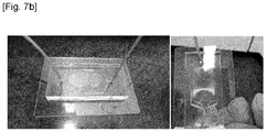
- the shape of the conventional micro device for solid phase extraction 1 is as shown in Figs. 7a and 7b .
- a dam 2 inside the micro device 1 so that beads 3 could not pass through but only the fluid flows.
- differential pressure is generated.
- a dam is installed on the left side, the right side, and the center of the device. Accordingly, a larger amount of fluid flows in the left and right directions, in which filling distance of the beads is relatively short. As a result, there is generated a non-uniform flow distribution of the fluid.
- the present invention provides a solid phase extraction method with a micro device having a dam-forming portion including a dam, the method comprising the steps of:
- the micro device for solid phase comprises an inlet for injecting a solvent and a filler; an outlet for discharging the solvent; and a dam-forming portion located between the inlet and the outlet, the dam-forming portion including a dam that allows only the solvent to flow through but the filler not to pass through, wherein each of the dam-forming portion and the dam has a circular cross section with respect to a central axis in a direction in which the inlet extends, the cross section being perpendicular to the central axis, and wherein the filler is filled in the form of disk with respect to the central axis in the dam-forming portion.
- the rotational angular velocity of the micro device for solid phase extraction may be defined in Equation 1-1 below: ⁇ > g r dam cos 90 ° ⁇ ⁇ wherein,
- each of the inlet, the outlet, the dam-forming portion, and the dam has a circular cross section with respect to a central axis in a direction in which the inlet extends, the cross section being perpendicular to the central axis, and each of the diameter of the inlet and the diameter of the outlet may be smaller than the diameter of the dam-forming portion.
- the rear end portion of the dam which is a surface facing the inlet of the dam may have a conical shape protruding toward the inlet.
- the micro device for solid phase extraction has a first end portion connected to the inlet and a second end portion connected to the outlet which are both ends of the dam-forming portion, wherein the dam may be located closer to the second end portion than the first end portion, and the dam may be located by a predetermined distance away from the second end portion.
- each of the second end portion and the surface facing the second end portion of the dam may have a shape protruding toward the outlet.
- each of the second end portion and the surface facing the second end portion of the dam may have a conical shape protruding toward the outlet.
- the filler may be in the form of beads.
- the micro device for solid phase extraction is rotated by a motor
- the motor includes a driving unit for providing rotational power, a rotation shaft connected to the driving unit, and a head connected to the rotation shaft
- the micro device for solid phase extraction may be rotated by contacting an outer surface of the micro device for solid phase extraction with the head of the motor.
- Figs. 1a to 1c show a front view of an embodiment of a micro device for solid phase extraction used in the solid phase extraction method of the present invention.
- the micro device for solid phase extraction 10 includes an inlet 100, a dam-forming portion 200, and an outlet 300.
- a filler 400 e.g., beads
- a solvent are injected through the inlet 100 and the injected filler 400 and solvent move into the dam-forming portion 200 connected to the inlet 100.
- the filler 400 is filled in the rear of the dam 210 in the dam-forming portion 200, and the solvent is discharged through the outlet 300 connected to the dam-forming portion 200 via the side surface of the dam 210.
- the dam-forming portion 200 of the micro device for solid phase extraction 10 used in the present invention has a shape of cylinder having a circular cross section (or disk having a predetermined length) with respect to a central axis in a direction in which the inlet extends, the cross section being perpendicular to the central axis.
- the dam-forming portion 200 includes a dam 210 on the side of outlet 300. With respect to both ends of the dam-forming portion having a cylindrical shape, an end of the dam-forming portion 200 connected to the inlet 100 is referred to as a first end portion 220 and an end of the dam-forming portion 200 is connected to the outlet 300 is referred to as a second end portion 230.
- the dam 210 is located close to the second end portion 230 of the dam-forming portion 200 and the dam 210 is located by a predetermined distance away from the second end portion 230 so that the solvent can flow toward the outlet 300.
- the dam 210 may be manufactured by a perforated plate having holes with a size smaller than that of the filler 400, or a mesh structure such that the filler 400 could not pass therethrough. In this case, the solvent may flow out to the outlet 300, passing through the dam 210 as well as the side surface of the dam 210.
- the second end portion 230 protrudes toward the outlet 300, and for example, may have a conical shape as shown in Fig. 1a , in order to minimize resistance due to the second end portion 230 when the solvent which passed by the dam 210 moves toward the outlet 300 in the dam-forming portion 200.
- the dam 210 also has a circular cross section with respect to a central axis in a direction in which the inlet extends, the cross section being perpendicular to the central axis.
- the front end portion 210a of the dam 210 (the surface where the dam 210 faces the second end portion 230 of the dam-forming portion 200, i.e., the surface facing the outlet 300 of the dam 210) may have a conical shape, like the second end portion 230 having a conical shape.
- the rear end portion 210b of the dam 210 may also have a conical shape. That is, the inclination angle ⁇ of the rear end portion 210b of the dam 210 is greater than 0 °.
- ⁇ may be between 0 ° and 60 °.
- the filler 400 when the filler 400 is injected into the inlet 100 alone without being mixed with the fluid, the filler 400 may accumulate from the side closer to the inlet 100 of the rear end portion 210b of the dam 210 and then the inlet 100 may be blocked by the filler 400 (see Fig. 5 ).
- the rear end portion 210b of the dam 210 also has a conical shape, so that the filler 400 does not accumulate near the inlet 100 but move radially along the inclined surface of the rear end portion 210b of the dam 210 to accumulate the filler 400.
- the value of ⁇ may be greater than an angle of repose of powder (i.e., filler 400) (i.e., when the rear end portion 210b of the dam 210 as shown in Fig. 5 has a flat surface, an angle of the accumulated filler 400 relative to the rear end portion 210b of the dam 210 having a flat surface). If the value of ⁇ is greater than the angle of repose of the powder, the filler 400 may move more smoothly along the inclined rear end portion 210b of the dam 210.
- the angle of repose of the powder has various values for various environments in which the present invention is implemented.
- Fig. 2 illustrates the shape of the filler 400 filled in the form of a disk in the rear end portion 210b of the dam 210 when viewed in the direction of the arrow (*) of Fig. 1a .
- the shape in which the filler 400 is filled is indicated by the reference numeral 200a.
- the diameter of the dam-forming portion 200 is equal to the diameter of the dam 210
- a protruded portion 240 in which a side surface surrounding the portion where the dam 210 is located in the dam-forming portion 200 is further protruded so that the protruded portion 240 allows the solvent to move between the side surface of the dam 210 and the inner surface of the dam-forming portion 200.
- the diameter of the second end portion 230 of the dam-forming portion 200 may be greater than the diameter of the first end portion 220 of the dam-forming portion 200.
- the solvent may pass between the fillers 400, pass by the protruded portion 240 of the dam-forming portion 200 and pass by a space between the second end portion 230 of the dam-forming portion 200 and the dam 210, and then move toward the outlet 300.
- a solvent inlet 250 which is the inlet of the space into which the solvent flows between the side surface of the dam 210 and the inner surface of the dam-forming portion 200, has a width smaller than the diameter of the filler 400.
- the inlet 100 and the outlet 300 may be connected to the dam-forming portion 200 and formed integrally with the dam-forming portion 200.
- Each of the inlet 100 and the outlet 300 may have a long cylindrical shape, for example.
- each of the inlet 100 and the outlet 300 may be located on the same line with respect to the center axis in a longitudinal direction of the dam-forming portion 200.
- the diameter of each of the inlet 100 and the outlet 300 is smaller than the diameter of the dam-forming portion 200.
- a diameter of the filler 400 may be 35 ⁇ m to 60 ⁇ m.
- a diameter of the inlet 100 may be 0.5 mm to 10 mm, and a length of the inlet 100 may be about 5 mm.
- a diameter of the outlet 300 may be 0.5 mm to 10 mm, and a length of the outlet 300 may be about 5 mm.
- a length from the first end portion 220 of the dam-forming portion 200 to the rear end portion 210b of the dam 210 i.e., a length of the region in which the filler 400 can be filled
- a length from the front end portion 210a of the dam 210 to the second end portion 230 may be 0.1 mm to 2 mm.
- a width of the solvent inlet 250 of the protruded portion 240 may be 30 ⁇ m to 35 ⁇ m to prevent the filler 400 from passing through.
- the dimensions shown in Fig. 1c are merely examples, and the present invention is not limited thereto, and various modifications and changes may be made to the various environments in which the present invention is implemented.
- the dam-forming portion 200 and the dam 210 are designed to be radially symmetric from the central axis so that the fillers 400 are filled at the same distance. Accordingly, the shape of the region 200a filled with the filler 400 becomes a disk shape as shown in Fig. 2 , and the inlet 100 and the outlet 300 are located on the central axis.
- each of the dam-forming portion 200 and the dam 210 has a circular cross section perpendicular to the central axis in the direction in which the inlet 100 extends.
- the filler 400 is filled in the form of disk with respect to the central axis.
- the cross section has a circular shape, the filler 400 is formed in the fluid flow direction with the same distribution from the central axis of the micro device for solid phase extraction 10, thereby eliminating unnecessary volume and maximizing the efficiency of solid phase extraction.
- Fig. 3 shows a front view of other embodiment of the micro device for solid phase extraction 10' used in the present invention, in which the dam-forming portion 200 of the micro device for solid phase extraction of Fig. 1a is partially modified.
- the rear end portion 210b of the dam 210 may also have a conical shape.
- the solvent inlet 250' which is the inlet of the space through which the solvent flows between the side surface of the dam 210 and the inner surface of the dam-forming portion 200', has a width smaller than the diameter of the filler 400.
- Fig. 4a shows a front view of another embodiment of the micro device for solid phase extraction 10" used in the solid phase extraction method of the present invention, in which the dam 210 of the micro device for solid phase extraction of Fig. 1a is partially modified.
- Fig. 4b shows only the dam 210" of the micro device for solid phase extraction 10" of Fig. 4a .
- the rear end portion 210"b of the dam 210" (the surface facing the first end portion 220 of the dam-forming portion 200' may also have a conical shape. Referring to Figs.
- the dam 210" may be divided into a first portion 215"a including the front end portion 210"a and a second portion 215"b including the rear end portion 210"b.
- a maximum diameter D2 in the circular cross section perpendicular to the central axis of the second portion 215"b (i.e., the central axis in a direction in which the inlet extends), that is, a diameter of the bottom of the conical shape of the second portion 215"b, is small that a maximum diameter D1 in the circular cross section perpendicular to the central axis of the first portion 215"a, that is, a diameter of the bottom of the conical shape of the first portion 210"a.
- the solid phase extraction method according to the present invention comprises the step (S100) of injecting a solvent and a filler 400 into an inlet 100 of the micro device for solid phase extraction (10, 10', 10") to move to a dam-forming portion including a dam adjusted to allow only the solvent to flow through but the filler not to pass through, thereby adsorbing a material to be separated onto the filler 400 in the dam-forming portion; and the step (S200) of extracting the adsorbed material to be separated from the filler 400.
- the solid phase extraction method according to the present invention further comprises the step (S300) of rotating the micro device for solid phase extraction (10, 10', 10") about the central axis.
- the step (S300) of rotating the solid state extraction micro device (10, 10', 10") about the central axis may performed in any one step of the step (S100) of adsorbing a material to be separated to the filler 400 and the step (S200) of extracting the adsorbed material to be separated from the filler 400.
- step (S100) of injecting a solvent and a filler 400 into an inlet 100 of the micro device for solid phase extraction (10, 10', 10") to adsorb a material to be separated onto the filler 400 the injected solvent passes through the dam-forming portion (200, 200') and the target material (i.e., the material to be separated) is adsorbed on the filler 400 filled by the dam (210, 210").
- step (S300) of extracting the adsorbed material a process of injecting a solvent capable of dissolving the material adsorbed on the filler 400 is performed.
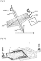
- Fig. 5 illustrates the case where the micro devices for solid phase extraction (10, 10', 10") are positioned in an inclined state with respect to the gravity direction, in particular the case where the micro device for the solid phase extraction (10") of Fig. 4a among the micro devices for solid phase extraction (10, 10', 10") is positioned in an inclined state with respect to the gravity direction.
- the central axis in a direction in which the inlet of the micro device for solid phase extraction (10, 10', 10") extends (hereinafter referred to as "the central axis of the micro device for solid phase extraction") is inclined by ⁇ from the axis of the horizontal plane (i.e., the plane perpendicular to the gravity direction).
- the micro device for solid phase extraction (10, 10', 10" is designed to be inclined by various angles ( ⁇ ), considering manufacturing tolerance and installation mistake such as misalignment of the connection shaft between the inlet 100 and the outlet 300.
- ⁇ the angle at which the central axis of the micro device for solid phase extraction is inclined by ⁇ from the axis of the horizontal plane (i.e., the plane perpendicular to the gravity direction) is called an orientation of the micro device for solid phase extraction, and ⁇ is in a range of 0 ⁇ ⁇ ⁇ 90.
- the solvent or the filler 400 injected into the inlet 100 may be biased and positioned in the dam-forming unit 200 due to gravity. Accordingly, there is a possibility that the uniform solid phase extraction from the solvent may not be implemented.
- the micro device for solid phase extraction (10, 10', 10") rotates about the central axis (S300).
- the central axis of the micro device for solid phase extraction (10, 10', 10") is a rotation axis.
- the angular velocity w at which the micro device for solid phase extraction (10, 10', 10" rotates is according to the Equation 1 below. ⁇ > g r cos 90 ° ⁇ ⁇
- g is an acceleration of gravity
- r is a radius of the micro device
- ⁇ is an orientation of the micro device (the angle at which the micro device is inclined in the gravity direction).
- the radius r of the micro device corresponds to the radius of the dam-forming portion (200, 200').
- the centrifugal force F c should be larger than the force F g received by the particles due to gravity, and in this regard, see Equation 2 below.
- m is the mass of the individual particle of the filler 400 at a distance r filler from the central axis in the micro device for solid phase extraction (10, 10', 10").
- Equation 4 The distance r filler from the central axis to the filler 400 filled in the micro device for solid phase extraction (10, 10', 10") is close to the radius ( r ) of the micro device for solid phase extraction (10, 10', 10"). It is expressed as Equation 4 as follows. r filler ⁇ r
- Equation 5 and Equation 6 the condition of the rotational angular velocity ⁇ of rotating the micro device for solid phase extraction (10, 10', 10") for uniform distribution of charging flow rate in the step (S200) of rotating the micro device for solid phase extraction (10, 10', 10"), can be derived from Equation 1 below.
- g is an acceleration of gravity
- r is a radius of the micro device
- ⁇ is an orientation of the micro device.
- the angular velocity ⁇ at which the micro device for solid phase extraction (10, 10', 10") rotates may be, for example, 1.5 times or more the value of g r cos 90 ° ⁇ ⁇ , or for example 10,000 times or less the value of g r cos 90 ° ⁇ ⁇ , or for example 1.5 time or more and 10,000 times or less the value of g r cos 90 ° ⁇ ⁇ .
- the angular velocity w at which the micro device for solid phase extraction (10, 10', 10" rotates is preferably as large as possible within the range in which solid phase extraction is performed by injecting the solvent or beads into the device (10, 10', 10").
- the distance r filler from the central axis to the filler 400 filled in the micro device for solid phase extraction (10, 10', 10") is close to the radius ( r ) of the micro device for solid phase extraction (10, 10', 10"), in particular to the radius ( r dam ) of the dam (210, 210") of the micro device for solid phase extraction (10, 10', 10"). It is expressed as Equation 4-1 as follows. r filler ⁇ r dam
- Equation 5-1 and Equation 6 are substituted into Equation 2 respectively, the condition of the rotational angular velocity ⁇ of rotating the micro device for solid phase extraction (10, 10', 10") for uniform distribution of charging flow rate in the step (S200) of rotating the micro device for solid phase extraction (10, 10', 10"), can be derived from Equation 1-1 below.
- ⁇ > g r dam cos 90 ° ⁇ ⁇
- the dam 210" may be divided into a first portion 215"a including the front end portion 210"a and a second portion 215"b including the rear end portion 210"b. If desired, r dam may be a radius of the first portion 215"a including the front end portion 210"a, or a radius of the second portion 215"b including the rear end portion 210"b.
- the angular velocity ⁇ at which the micro device for solid phase extraction (10, 10', 10") rotates may be, for example, 1.5 times or more the value of g r dam cos 90 ° ⁇ ⁇ , or for example 10,000 times or less the value of g r dam cos 90 ° ⁇ ⁇ , or for example 1.5 time or more and 10,000 times or less the value of g r dam cos 90 ° ⁇ ⁇ .
- the angular velocity ⁇ at which the micro device for solid phase extraction (10, 10', 10" rotates is preferably as large as possible within the range in which solid phase extraction is performed by injecting the solvent or beads into the device (10, 10', 10").
- the step (S300) of rotating the micro device for solid phase extraction (10, 10', 10") may comprise rotating the micro device for solid phase extraction (10, 10', 10") with the condition of the angular velocity ⁇ of Equation 1.
- the step (S300) of rotating the micro device for solid phase extraction (10, 10', 10") may comprise rotating the micro device for solid phase extraction (10, 10', 10") with the condition of the angular velocity ⁇ of Equation 1-1.
- Fig. 5 illustrates the case where the micro device for the solid phase extraction (10") of Fig. 4a among the micro devices for the solid phase extraction (10, 10', 10" is positioned in an inclined state.
- the solid phase extraction method of the present invention is not limited to the case of the micro device for the solid phase extraction (10") of Fig. 4a , and is equally applied to the micro device for the solid phase extraction (10, 10').
- the solid phase extraction method of the present invention is not limited to the case where the rear end portion (210b, 210"b) of the dam has a conical shape as shown in Fig. 1 and Fig. 4b , and is equally applied to the case where the rear end portion (210b, 210"b) has a flat planar shape.
- Fig. 6 shows a case where a rotary motor 500 is provided to rotate the micro device for solid phase extraction (10, 10', 10") in the solid phase extraction method of the present invention.
- the rotary motor 500 includes a driving unit (not shown) for providing rotational power, a rotation shaft 510 connected to the driving unit, and a head 520 connected to the rotation shaft 510.
- the rotary motor 500 is rotated by the rotation of the driving unit.
- the rotary motor 500 may be a microminiature rotary motor.
- the present invention is not limited to the case illustrated in Fig.
- a rotary motor 500 may be provided near the inlet 100 or the outlet 300 to rotate the micro device for solid phase extraction (10, 10', 10"). Modifications and variations are possible by applying various means or methods other than the rotary motor 500 as long as they can rotate the micro device for solid phase extraction (10, 10', 10").
Landscapes
- Chemical & Material Sciences (AREA)
- Chemical Kinetics & Catalysis (AREA)
- Health & Medical Sciences (AREA)
- Analytical Chemistry (AREA)
- General Health & Medical Sciences (AREA)
- Life Sciences & Earth Sciences (AREA)
- General Physics & Mathematics (AREA)
- Biochemistry (AREA)
- Physics & Mathematics (AREA)
- Immunology (AREA)
- Pathology (AREA)
- Dispersion Chemistry (AREA)
- Hematology (AREA)
- Clinical Laboratory Science (AREA)
- Molecular Biology (AREA)
- Extraction Or Liquid Replacement (AREA)
- Physical Or Chemical Processes And Apparatus (AREA)
- Treatment Of Liquids With Adsorbents In General (AREA)
- Separation Of Solids By Using Liquids Or Pneumatic Power (AREA)
Abstract
Description
- This application claims the benefit of priorities to Korean Patent Application Nos.
10-2018-0097181, filed on August 21, 2018 10-2019-0095313, filed on August 6, 2019 - The present invention relates to a method of solid phase extraction with a micro device, and more particularly, to a method of solid phase extraction with a micro device capable of performing solid phase extraction by adding a filler and a solvent.
- Solid phase extraction is a method in which a target material is adsorbed onto a filler having a specific property, such as beads, and purified and concentrated using a solvent to perform a pretreatment. In this case, a device for packing the filler is required. A micro device having a small size is used in order to increase a recovery rate and shorten a pretreatment time. In addition, a micro device is used to detect trace amounts of materials. The use of a micro device has advantages of being environmentally friendly since it can reduce solvent consumption.
- The shape of the conventional micro device for
solid phase extraction 1 is as shown inFigs. 7a and7b . There is provided adam 2 inside themicro device 1 so thatbeads 3 could not pass through but only the fluid flows. At this time, as the flow path is reduced due to packing of beads in therear end portion 210b of the dam, differential pressure is generated. The smaller the porosity of voids, the greater the differential pressure. In the conventional micro device ofFigs. 7a and7b , a dam is installed on the left side, the right side, and the center of the device. Accordingly, a larger amount of fluid flows in the left and right directions, in which filling distance of the beads is relatively short. As a result, there is generated a non-uniform flow distribution of the fluid. - In order to solve the non-uniform flow distribution of the fluid of the conventional micro device for solid phase extraction, there is a need for a method of solid phase extraction with a new type of a micro device for solid phase extraction capable of realizing uniform extraction by a uniform flow rate of fluid, in particular, a method of solid phase extraction, by allowing a new type of a micro device for solid phase extraction to be uniformly filled with fillers.
- In order to solve the above problems, the present invention provides a solid phase extraction method with a micro device having a dam-forming portion including a dam, the method comprising the steps of:
- (i) injecting a solvent and a filler into the micro device to move to a dam-forming portion including a dam adjusted to allow only the solvent to flow through but the filler not to pass through, thereby adsorbing a material to be separated onto the filler in the dam-forming portion; and
- (ii) extracting the adsorbed material to be separated from the filler,
- ω is a rotational angular velocity of the micro device,
- g is an acceleration of gravity,
- r is a radius of the micro device,
- ϕ is an orientation of the micro device, and is in the range of 0 <ϕ <90.
- The micro device for solid phase comprises an inlet for injecting a solvent and a filler; an outlet for discharging the solvent; and a dam-forming portion located between the inlet and the outlet, the dam-forming portion including a dam that allows only the solvent to flow through but the filler not to pass through, wherein each of the dam-forming portion and the dam has a circular cross section with respect to a central axis in a direction in which the inlet extends, the cross section being perpendicular to the central axis, and wherein the filler is filled in the form of disk with respect to the central axis in the dam-forming portion.
- In addition, in the solid phase extraction method according to the present invention, the rotational angular velocity of the micro device for solid phase extraction may be defined in Equation 1-1 below:

- ω is a rotational angular velocity of the micro device,
- g is an acceleration of gravity,
- rdam is a radius of the dam included in the micro device,
- ϕ is an orientation of the micro device, and is in the range of 0 <ϕ <90.
- In the solid phase extraction method according to the present invention, each of the inlet, the outlet, the dam-forming portion, and the dam has a circular cross section with respect to a central axis in a direction in which the inlet extends, the cross section being perpendicular to the central axis, and each of the diameter of the inlet and the diameter of the outlet may be smaller than the diameter of the dam-forming portion.
- In addition, in the solid phase extraction method according to the present invention, the rear end portion of the dam which is a surface facing the inlet of the dam may have a conical shape protruding toward the inlet.
- In addition, in the solid phase extraction method according to the present invention, the micro device for solid phase extraction has a first end portion connected to the inlet and a second end portion connected to the outlet which are both ends of the dam-forming portion, wherein the dam may be located closer to the second end portion than the first end portion, and the dam may be located by a predetermined distance away from the second end portion.
- In addition, in the solid phase extraction method according to the present invention, each of the second end portion and the surface facing the second end portion of the dam may have a shape protruding toward the outlet.
- In addition, in the solid phase extraction method according to the present invention, each of the second end portion and the surface facing the second end portion of the dam may have a conical shape protruding toward the outlet.
- In addition, in the solid phase extraction method according to the present invention, the filler may be in the form of beads.
- In addition, in the solid phase extraction method according to the present invention,
the micro device for solid phase extraction is rotated by a motor,
the motor includes a driving unit for providing rotational power, a rotation shaft connected to the driving unit, and a head connected to the rotation shaft, and
the micro device for solid phase extraction may be rotated by contacting an outer surface of the micro device for solid phase extraction with the head of the motor. - According to the method of solid phase extraction with the micro device for solid phase extraction of the present invention, it is advantageous that a uniform fluid flow is formed along the central axis of the micro device for solid phase extraction without biasing the flow of the filler and solvent, thereby realizing uniform solid phase extraction.
-
-
Figs. 1a to 1c show a front view of an embodiment of a micro device for solid phase extraction used in the solid phase extraction method of the present invention. -
Fig. 2 shows a top view of a micro device for solid phase extraction ofFig. 1a . -
Fig. 3 shows a front view of other embodiment of a micro device for solid phase extraction used in the solid phase extraction method of the present invention. -
Figs. 4a and4b show a front view and a main part of another embodiment of a micro device for solid phase extraction used in the solid phase extraction method of the present invention. -
Fig. 5 shows the conditions for the fluid having a uniform flow rate without biasing the flow of the filler and solvent in the solid phase extraction method of the present invention. -
Fig. 6 shows a case where a motor is provided to rotate the micro device for solid phase extraction in the solid phase extraction method of the present invention. -
Fig. 7a and7b show a perspective view of a micro device for solid phase extraction according to the prior art and show an experimental example of the flow of the solvent and beads. - Hereinafter, a micro device for solid phase extraction used in the present invention and a solid phase extraction method using the micro device for solid phase extraction will be described in detail. The accompanying drawings, which are included to provide a further understanding of the invention, illustrate embodiments of the invention and are not intended to limit the technical scope of the present invention.
- In addition, the same or corresponding components will be denoted by the same reference numerals regardless of symbols, and redundant description thereof will be omitted. For convenience of explanation, the size and shape of each component shown may be exaggerated or reduced.
-
Figs. 1a to 1c show a front view of an embodiment of a micro device for solid phase extraction used in the solid phase extraction method of the present invention. The micro device forsolid phase extraction 10 includes aninlet 100, a dam-formingportion 200, and anoutlet 300. A filler 400 (e.g., beads) and a solvent are injected through theinlet 100 and the injectedfiller 400 and solvent move into the dam-formingportion 200 connected to theinlet 100. Thefiller 400 is filled in the rear of thedam 210 in the dam-formingportion 200, and the solvent is discharged through theoutlet 300 connected to the dam-formingportion 200 via the side surface of thedam 210. - The dam-forming
portion 200 of the micro device forsolid phase extraction 10 used in the present invention has a shape of cylinder having a circular cross section (or disk having a predetermined length) with respect to a central axis in a direction in which the inlet extends, the cross section being perpendicular to the central axis. The dam-formingportion 200 includes adam 210 on the side ofoutlet 300. With respect to both ends of the dam-forming portion having a cylindrical shape, an end of the dam-formingportion 200 connected to theinlet 100 is referred to as afirst end portion 220 and an end of the dam-formingportion 200 is connected to theoutlet 300 is referred to as asecond end portion 230. Thedam 210 is located close to thesecond end portion 230 of the dam-formingportion 200 and thedam 210 is located by a predetermined distance away from thesecond end portion 230 so that the solvent can flow toward theoutlet 300. However, the present invention is not limited to the above. For example, thedam 210 may be manufactured by a perforated plate having holes with a size smaller than that of thefiller 400, or a mesh structure such that thefiller 400 could not pass therethrough. In this case, the solvent may flow out to theoutlet 300, passing through thedam 210 as well as the side surface of thedam 210. - The
second end portion 230 protrudes toward theoutlet 300, and for example, may have a conical shape as shown inFig. 1a , in order to minimize resistance due to thesecond end portion 230 when the solvent which passed by thedam 210 moves toward theoutlet 300 in the dam-formingportion 200. - As described above, the
dam 210 also has a circular cross section with respect to a central axis in a direction in which the inlet extends, the cross section being perpendicular to the central axis. As shown inFig. 1a , thefront end portion 210a of the dam 210 (the surface where thedam 210 faces thesecond end portion 230 of the dam-formingportion 200, i.e., the surface facing theoutlet 300 of the dam 210) may have a conical shape, like thesecond end portion 230 having a conical shape. - In addition, according to the present invention, as shown in
Fig. 1a , therear end portion 210b of the dam 210 (the surface where thedam 210 faces thefirst end portion 220 of the dam-formingportion 200, i.e., the surface facing theinlet 100 of the dam 210) may also have a conical shape. That is, the inclination angle θ of therear end portion 210b of thedam 210 is greater than 0 °. For example, θ may be between 0 ° and 60 °. - First, with the flat surface of the
rear end portion 210b of the dam 210 (that is, when θ = 0 ° inFig. 1a ), when thefiller 400 is injected into theinlet 100 alone without being mixed with the fluid, thefiller 400 may accumulate from the side closer to theinlet 100 of therear end portion 210b of thedam 210 and then theinlet 100 may be blocked by the filler 400 (seeFig. 5 ). - According to the present invention, in order to prevent such a phenomenon, the
rear end portion 210b of thedam 210 also has a conical shape, so that thefiller 400 does not accumulate near theinlet 100 but move radially along the inclined surface of therear end portion 210b of thedam 210 to accumulate thefiller 400. - At this time, the value of θ may be greater than an angle of repose of powder (i.e., filler 400) (i.e., when the
rear end portion 210b of thedam 210 as shown inFig. 5 has a flat surface, an angle of the accumulatedfiller 400 relative to therear end portion 210b of thedam 210 having a flat surface). If the value of θ is greater than the angle of repose of the powder, thefiller 400 may move more smoothly along the inclinedrear end portion 210b of thedam 210. The angle of repose of the powder has various values for various environments in which the present invention is implemented. -
Fig. 2 illustrates the shape of thefiller 400 filled in the form of a disk in therear end portion 210b of thedam 210 when viewed in the direction of the arrow (*) ofFig. 1a . The shape in which thefiller 400 is filled is indicated by thereference numeral 200a. - Referring back to
Fig. 1a , in case that the diameter of the dam-formingportion 200 is equal to the diameter of thedam 210, there is further provided a protrudedportion 240 in which a side surface surrounding the portion where thedam 210 is located in the dam-formingportion 200 is further protruded so that the protrudedportion 240 allows the solvent to move between the side surface of thedam 210 and the inner surface of the dam-formingportion 200. In this case, the diameter of thesecond end portion 230 of the dam-formingportion 200 may be greater than the diameter of thefirst end portion 220 of the dam-formingportion 200. As shown by a flow line of the solvent inFig. 1a , the solvent may pass between thefillers 400, pass by the protrudedportion 240 of the dam-formingportion 200 and pass by a space between thesecond end portion 230 of the dam-formingportion 200 and thedam 210, and then move toward theoutlet 300. - A
solvent inlet 250, which is the inlet of the space into which the solvent flows between the side surface of thedam 210 and the inner surface of the dam-formingportion 200, has a width smaller than the diameter of thefiller 400. - As described above, the
inlet 100 and theoutlet 300 may be connected to the dam-formingportion 200 and formed integrally with the dam-formingportion 200. Each of theinlet 100 and theoutlet 300 may have a long cylindrical shape, for example. In addition, each of theinlet 100 and theoutlet 300 may be located on the same line with respect to the center axis in a longitudinal direction of the dam-formingportion 200. The diameter of each of theinlet 100 and theoutlet 300 is smaller than the diameter of the dam-formingportion 200. - A size of the micro device for
solid phase extraction 10, for example, as shown inFig. 1c , a diameter of the micro device for solid phase extraction 10 (i.e., a diameter of themicro device 10 including the protrudedportion 240 of the dam-forming portion 200) may be 25 mm to 32 mm, and a total length of the micro device for solid phase extraction 10 (i.e., a total length of the micro device including theinlet 100, the dam-formingportion 200 and the outlet 300) may be about 10.3 mm to 10.45 mm, and in one embodiment may be about 10 mm. A diameter of thefiller 400 may be 35 µm to 60 µm. A diameter of theinlet 100 may be 0.5 mm to 10 mm, and a length of theinlet 100 may be about 5 mm. A diameter of theoutlet 300 may be 0.5 mm to 10 mm, and a length of theoutlet 300 may be about 5 mm. A length from thefirst end portion 220 of the dam-formingportion 200 to therear end portion 210b of the dam 210 (i.e., a length of the region in which thefiller 400 can be filled) may be 0.5 mm to 2 mm. A length from thefront end portion 210a of thedam 210 to thesecond end portion 230 may be 0.1 mm to 2 mm. A width of thesolvent inlet 250 of the protrudedportion 240 may be 30 µm to 35 µm to prevent thefiller 400 from passing through. The dimensions shown inFig. 1c are merely examples, and the present invention is not limited thereto, and various modifications and changes may be made to the various environments in which the present invention is implemented. - According to the present invention, since the same filling distance of the
filler 400 from the central axis in the longitudinal direction of the dam-formingportion 200 generates a similar differential pressure, a uniform flow distribution of the solvent in the micro device forsolid phase extraction 10 can be achieved. Therefore, the dam-formingportion 200 and thedam 210 are designed to be radially symmetric from the central axis so that thefillers 400 are filled at the same distance. Accordingly, the shape of theregion 200a filled with thefiller 400 becomes a disk shape as shown inFig. 2 , and theinlet 100 and theoutlet 300 are located on the central axis. That is, each of the dam-formingportion 200 and thedam 210 has a circular cross section perpendicular to the central axis in the direction in which theinlet 100 extends. In the dam-formingportion 200, thefiller 400 is filled in the form of disk with respect to the central axis. As such, when the cross section has a circular shape, thefiller 400 is formed in the fluid flow direction with the same distribution from the central axis of the micro device forsolid phase extraction 10, thereby eliminating unnecessary volume and maximizing the efficiency of solid phase extraction. -
Fig. 3 shows a front view of other embodiment of the micro device for solid phase extraction 10' used in the present invention, in which the dam-formingportion 200 of the micro device for solid phase extraction ofFig. 1a is partially modified. In the micro device for solid phase extraction 10' ofFig. 3 , similarly as that shown inFig. 1a , therear end portion 210b of the dam 210 (the surface facing the first end portion 220' of the dam-forming portion 200') may also have a conical shape. As shown inFig. 3 , in case that the diameter of thedam 210 is smaller than the diameter of the dam-forming portion 200', the solvent can pass by the side surface of thedam 210, and therefore the dam-forming portion 200' may not need a protruded portion. In this case, a solvent inlet 250', which is the inlet of the space through which the solvent flows between the side surface of thedam 210 and the inner surface of the dam-forming portion 200', has a width smaller than the diameter of thefiller 400. -
Fig. 4a shows a front view of another embodiment of the micro device forsolid phase extraction 10" used in the solid phase extraction method of the present invention, in which thedam 210 of the micro device for solid phase extraction ofFig. 1a is partially modified.Fig. 4b shows only thedam 210" of the micro device forsolid phase extraction 10" ofFig. 4a . In the micro device forsolid phase extraction 10" ofFig. 4a , similarly as that shown inFig. 1a , therear end portion 210"b of thedam 210" (the surface facing thefirst end portion 220 of the dam-forming portion 200' may also have a conical shape. Referring toFigs. 4a and4b , thedam 210" may be divided into afirst portion 215"a including thefront end portion 210"a and asecond portion 215"b including therear end portion 210"b. A maximum diameter D2 in the circular cross section perpendicular to the central axis of thesecond portion 215"b (i.e., the central axis in a direction in which the inlet extends), that is, a diameter of the bottom of the conical shape of thesecond portion 215"b, is small that a maximum diameter D1 in the circular cross section perpendicular to the central axis of thefirst portion 215"a, that is, a diameter of the bottom of the conical shape of thefirst portion 210"a. Therefore, when thefiller 400 moves radially along the inclined surface of therear end portion 210"b of the conical shape and accumulates toward the edge of thedam 210", there is an advantage that the value of θ can be made larger while ensuring a sufficient space for thefiller 400 to accumulate toward the edge of thedam 210". - Next, a solid phase extraction method and a solid phase extraction condition according to the present invention will be described with reference to
Fig. 5 . First, The solid phase extraction method according to the present invention comprises the step (S100) of injecting a solvent and afiller 400 into aninlet 100 of the micro device for solid phase extraction (10, 10', 10") to move to a dam-forming portion including a dam adjusted to allow only the solvent to flow through but the filler not to pass through, thereby adsorbing a material to be separated onto thefiller 400 in the dam-forming portion; and the step (S200) of extracting the adsorbed material to be separated from thefiller 400. In addition, the solid phase extraction method according to the present invention further comprises the step (S300) of rotating the micro device for solid phase extraction (10, 10', 10") about the central axis. The step (S300) of rotating the solid state extraction micro device (10, 10', 10") about the central axis may performed in any one step of the step (S100) of adsorbing a material to be separated to thefiller 400 and the step (S200) of extracting the adsorbed material to be separated from thefiller 400. - In the step (S100) of injecting a solvent and a
filler 400 into aninlet 100 of the micro device for solid phase extraction (10, 10', 10") to adsorb a material to be separated onto thefiller 400, the injected solvent passes through the dam-forming portion (200, 200') and the target material (i.e., the material to be separated) is adsorbed on thefiller 400 filled by the dam (210, 210"). In the step (S300) of extracting the adsorbed material, a process of injecting a solvent capable of dissolving the material adsorbed on thefiller 400 is performed. -
Fig. 5 illustrates the case where the micro devices for solid phase extraction (10, 10', 10") are positioned in an inclined state with respect to the gravity direction, in particular the case where the micro device for the solid phase extraction (10") ofFig. 4a among the micro devices for solid phase extraction (10, 10', 10") is positioned in an inclined state with respect to the gravity direction. - More specifically, the central axis in a direction in which the inlet of the micro device for solid phase extraction (10, 10', 10") extends (hereinafter referred to as "the central axis of the micro device for solid phase extraction") is inclined by ϕ from the axis of the horizontal plane (i.e., the plane perpendicular to the gravity direction).
- As shown in
Fig. 5 , the micro device for solid phase extraction (10, 10', 10") is designed to be inclined by various angles (ϕ), considering manufacturing tolerance and installation mistake such as misalignment of the connection shaft between theinlet 100 and theoutlet 300. Here, the angle at which the central axis of the micro device for solid phase extraction is inclined by ϕ from the axis of the horizontal plane (i.e., the plane perpendicular to the gravity direction) is called an orientation of the micro device for solid phase extraction, and ϕ is in a range of 0 <ϕ <90. - In the case where the micro device for solid phase extraction (10, 10', 10") (more specifically, the central axis of the micro device for solid phase extraction) is inclined from the axis of the horizontal plane (i.e., the plane perpendicular to the gravity direction), the solvent or the
filler 400 injected into theinlet 100 may be biased and positioned in the dam-formingunit 200 due to gravity. Accordingly, there is a possibility that the uniform solid phase extraction from the solvent may not be implemented. - According to the present invention, however, in order to implement the uniform solid phase extraction by allowing the solvent and the
filler 400 to flow in a uniform flow rate without biasing, the micro device for solid phase extraction (10, 10', 10") rotates about the central axis (S300). At this time, the central axis of the micro device for solid phase extraction (10, 10', 10") is a rotation axis. - In addition, in the step (S300) of rotating the micro device for solid phase extraction (10, 10', 10") about the central axis, the angular velocity w at which the micro device for solid phase extraction (10, 10', 10") rotates is according to the
Equation 1 below.
- In the equation, g is an acceleration of gravity, r is a radius of the micro device, and ϕ is an orientation of the micro device (the angle at which the micro device is inclined in the gravity direction). The radius r of the micro device corresponds to the radius of the dam-forming portion (200, 200').
- In
Fig. 5 , the centrifugal force Fc should be larger than the force Fg received by the particles due to gravity, and in this regard, seeEquation 2 below.
- In addition, with regard to the centrifugal force Fc, see
Equation 3 to Equation 5 below.
- In the Equation, m is the mass of the individual particle of the
filler 400 at a distance rfiller from the central axis in the micro device for solid phase extraction (10, 10', 10"). - The distance rfiller from the central axis to the
filler 400 filled in the micro device for solid phase extraction (10, 10', 10") is close to the radius (r) of the micro device for solid phase extraction (10, 10', 10"). It is expressed as Equation 4 as follows.
- Accordingly, the centrifugal force (Fc) is expressed as Equation 5 below.

- With regard to the force Fg received by the particles due to gravity, see Equation 6 below.

- If Equation 5 and Equation 6 are substituted into
Equation 2 respectively, the condition of the rotational angular velocity ω of rotating the micro device for solid phase extraction (10, 10', 10") for uniform distribution of charging flow rate in the step (S200) of rotating the micro device for solid phase extraction (10, 10', 10"), can be derived fromEquation 1 below.
- In the equation, g is an acceleration of gravity, r is a radius of the micro device, and ϕ is an orientation of the micro device.
- Additionally, the angular velocity ω at which the micro device for solid phase extraction (10, 10', 10") rotates may be, for example, 1.5 times or more the value of

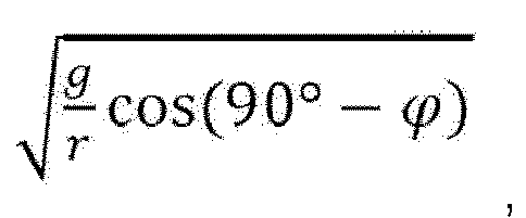

- Alternatively, the distance rfiller from the central axis to the
filler 400 filled in the micro device for solid phase extraction (10, 10', 10") is close to the radius (r) of the micro device for solid phase extraction (10, 10', 10"), in particular to the radius (rdam ) of the dam (210, 210") of the micro device for solid phase extraction (10, 10', 10"). It is expressed as Equation 4-1 as follows.
- Accordingly, the centrifugal force Fc is expressed as Equation 5-1 below.

- If Equation 5-1 and Equation 6 are substituted into
Equation 2 respectively, the condition of the rotational angular velocity ω of rotating the micro device for solid phase extraction (10, 10', 10") for uniform distribution of charging flow rate in the step (S200) of rotating the micro device for solid phase extraction (10, 10', 10"), can be derived from Equation 1-1 below.
- In the equation, g is an acceleration of gravity, rdam is a radius of the dam (210, 210") included in the micro device, and ϕ is an orientation of the micro device. Referring to
Figs. 4a to 4b , as described above, thedam 210" may be divided into afirst portion 215"a including thefront end portion 210"a and asecond portion 215"b including therear end portion 210"b. If desired, rdam may be a radius of thefirst portion 215"a including thefront end portion 210"a, or a radius of thesecond portion 215"b including therear end portion 210"b. - Additionally, the angular velocity ω at which the micro device for solid phase extraction (10, 10', 10") rotates may be, for example, 1.5 times or more the value of


- Additionally, the step (S300) of rotating the micro device for solid phase extraction (10, 10', 10") may comprise rotating the micro device for solid phase extraction (10, 10', 10") with the condition of the angular velocity ω of
Equation 1. Alternatively, the step (S300) of rotating the micro device for solid phase extraction (10, 10', 10") may comprise rotating the micro device for solid phase extraction (10, 10', 10") with the condition of the angular velocity ω of Equation 1-1. -
Fig. 5 illustrates the case where the micro device for the solid phase extraction (10") ofFig. 4a among the micro devices for the solid phase extraction (10, 10', 10") is positioned in an inclined state. However, the solid phase extraction method of the present invention is not limited to the case of the micro device for the solid phase extraction (10") ofFig. 4a , and is equally applied to the micro device for the solid phase extraction (10, 10'). In addition, the solid phase extraction method of the present invention is not limited to the case where the rear end portion (210b, 210"b) of the dam has a conical shape as shown inFig. 1 andFig. 4b , and is equally applied to the case where the rear end portion (210b, 210"b) has a flat planar shape. -
Fig. 6 shows a case where arotary motor 500 is provided to rotate the micro device for solid phase extraction (10, 10', 10") in the solid phase extraction method of the present invention. In exemplary embodiments, therotary motor 500 includes a driving unit (not shown) for providing rotational power, arotation shaft 510 connected to the driving unit, and ahead 520 connected to therotation shaft 510. Therotary motor 500 is rotated by the rotation of the driving unit. By contacting an outer surface of the micro device for solid phase extraction (10, 10', 10") with thehead 520, the micro device for solid phase extraction (10, 10', 10") can be rotated. Therotary motor 500 may be a microminiature rotary motor. The present invention is not limited to the case illustrated inFig. 6 , and arotary motor 500 may be provided near theinlet 100 or theoutlet 300 to rotate the micro device for solid phase extraction (10, 10', 10"). Modifications and variations are possible by applying various means or methods other than therotary motor 500 as long as they can rotate the micro device for solid phase extraction (10, 10', 10"). - It will be understood by those skilled in the art that various changes in form and details may be made therein without departing from the spirit and scope of the invention as defined by the appended claims. Therefore, it should be understood that the above-described embodiments are illustrative in all aspects and not restrictive. In addition, the scope of the present invention is indicated by the following claims rather than the above detailed description. Also, all changes or modifications derived from the meaning and scope of the claims and their equivalents should be construed as being included within the scope of the present invention.
-
S100: Step of injecting a solvent and a filler into an inlet of the micro device for solid phase extraction to adsorb a material to be separated onto the filler 400S200: Step of extracting the adsorbed material to be separated from the filler S300: Step of rotating the micro device for solid phase extraction 10: Micro device for solid phase extraction 100: Inlet 200: Dam-forming portion 210: Dam 220: First end portion 230: Second end portion 240: Protruded portion 250: Solvent inlet 300: Outlet 400: Filler

Claims (10)
- A solid phase extraction method with a micro device having a dam-forming portion including a dam, the method comprising the steps of:(i) injecting a solvent and a filler into the micro device to move to a dam-forming portion including a dam adjusted to allow only the solvent to flow through but the filler not to pass through, thereby adsorbing a material to be separated onto the filler in the dam-forming portion; and(ii) extracting the adsorbed material to be separated from the filler,wherein in one step of the steps (i) and (ii), the micro device is rotated about a central axis, and the rotation of the micro device is performed at an angular velocity defined by Equation 1 below.
 ω is a rotational angular velocity of the micro device,g is an acceleration of gravity,r is a radius of the micro device,ϕ is an orientation of the micro device, and is in the range of 0 <ϕ <90.
 - The solid phase extraction method according to claim 1, wherein the micro device comprises an inlet for injecting a solvent and a filler; an outlet for discharging the solvent; and a dam-forming portion located between the inlet and the outlet, the dam-forming portion including a dam that allows only the solvent to flow through but the filler not to pass through,
wherein each of the dam-forming portion and the dam has a circular cross section with respect to a central axis in a direction in which the inlet extends, the cross section being perpendicular to the central axis, and wherein the filler is filled in the form of disk with respect to the central axis in the dam-forming portion. - The solid phase extraction method according to claim 1, wherein the rotational angular velocity of the micro device for solid phase extraction is defined in Equation 1-1 below:
 ω is a rotational angular velocity of the micro device,g is an acceleration of gravity,rdam is a radius of the dam included in the micro device,ϕ is an orientation of the micro device, and is in the range of 0 <ϕ <90.
 - The solid phase extraction method according to claim 2,
wherein each of the inlet, the outlet, the dam-forming portion, and the dam has a circular cross section with respect to a central axis in a direction in which the inlet extends, the cross section being perpendicular to the central axis, and
wherein each of the diameter of the inlet and the diameter of the outlet is smaller than the diameter of the dam-forming portion. - The solid phase extraction method according to claim 2, wherein the rear end portion of the dam which is a surface facing the inlet of the dam has a conical shape protruding toward the inlet.
- The solid phase extraction method according to claim 2, wherein the micro device for solid phase extraction has both ends of the dam-forming portion, i.e., a first end portion connected to the inlet and a second end portion connected to the outlet, and wherein the dam is located closer to the second end portion than the first end portion, and the dam is located by a predetermined distance away from the second end portion.
- The solid phase extraction method according to claim 6, wherein each of the second end portion and the surface facing the second end portion of the dam has a shape protruding toward the outlet.
- The solid phase extraction method according to claim 7, wherein each of the second end portion and the surface facing the second end portion of the dam has a conical shape.
- The solid phase extraction method according to claim 1, wherein the filler is in the form of beads.
- The solid phase extraction method according to claim 1,
wherein the micro device is rotated by a motor,
wherein the motor includes a driving unit for providing rotational power, a rotation shaft connected to the driving unit, and a head connected to the rotation shaft, and
wherein the micro device is rotated by contacting an outer surface of the micro device with the head of the motor.
Applications Claiming Priority (3)
| Application Number | Priority Date | Filing Date | Title |
|---|---|---|---|
| KR20180097181 | 2018-08-21 | ||
| KR1020190095313A KR102318501B1 (en) | 2018-08-21 | 2019-08-06 | Solid Phase Extraction Using Micro device |
| PCT/KR2019/009901 WO2020040458A1 (en) | 2018-08-21 | 2019-08-07 | Solid phase extraction method using micro device |
Publications (3)
| Publication Number | Publication Date |
|---|---|
| EP3695890A1 true EP3695890A1 (en) | 2020-08-19 |
| EP3695890A4 EP3695890A4 (en) | 2021-02-17 |
| EP3695890B1 EP3695890B1 (en) | 2024-03-13 |
Family
ID=69805339
Family Applications (1)
| Application Number | Title | Priority Date | Filing Date |
|---|---|---|---|
| EP19851428.3A Active EP3695890B1 (en) | 2018-08-21 | 2019-08-07 | Solid phase extraction method using micro device |
Country Status (5)
| Country | Link |
|---|---|
| US (1) | US11260319B2 (en) |
| EP (1) | EP3695890B1 (en) |
| JP (1) | JP7007036B2 (en) |
| KR (1) | KR102318501B1 (en) |
| CN (1) | CN111405933B (en) |
Families Citing this family (1)
| Publication number | Priority date | Publication date | Assignee | Title |
|---|---|---|---|---|
| KR102245674B1 (en) * | 2017-11-17 | 2021-04-27 | 주식회사 엘지화학 | A Micro device for Solid Phase Extraction |
Family Cites Families (37)
| Publication number | Priority date | Publication date | Assignee | Title |
|---|---|---|---|---|
| CH574753A5 (en) | 1974-07-03 | 1976-04-30 | Bertrams Ag Hch | |
| US5976824A (en) * | 1993-11-24 | 1999-11-02 | Abbott Laboratories | Method and apparatus for collecting a cell sample from a liquid specimen |
| JPH09184830A (en) | 1995-12-28 | 1997-07-15 | Daicel Chem Ind Ltd | Apparatus and method for filling of filler as well as filler filling column assembly |
| EP1252495A2 (en) | 2000-02-02 | 2002-10-30 | PAWLISZYN, Janusz B. | Analytical devices based on diffusion boundary layer calibration and quantitative sorption |
| US20040154985A1 (en) * | 2003-02-07 | 2004-08-12 | Ferro Corporation | Method and apparatus for producing particles via supercritical fluid processing |
| JP4285387B2 (en) | 2004-03-31 | 2009-06-24 | 財団法人雑賀技術研究所 | Solid phase extraction cartridge |
| WO2007021814A2 (en) * | 2005-08-11 | 2007-02-22 | Eksigent Technologies, Llc | Plastic surfaces and apparatuses for reduced adsorption of solutes and methods of preparing the same |
| JP2007170903A (en) * | 2005-12-20 | 2007-07-05 | Showa Denko Kk | Solid phase extraction cartridge |
| KR101422572B1 (en) | 2006-09-05 | 2014-07-30 | 삼성전자주식회사 | Centrifugal-force microfluidic device for nucleic acid detection and microfluidic system including the same |
| KR101306341B1 (en) | 2006-09-05 | 2013-09-09 | 삼성전자주식회사 | Centrifugal force-based microfluidic device for nucleic acid extraction from biological sample and microfluidic system comprising the microfluidic system |
| US8124030B2 (en) * | 2007-05-08 | 2012-02-28 | The Regents Of The University Of California | Microfluidic device having regulated fluid transfer between elements located therein |
| KR101467561B1 (en) | 2007-09-28 | 2014-12-01 | 재단법인서울대학교산학협력재단 | A Method for Concentrating Samples Using a Real-Time Automated Solid-phase Extraction Method Combining Non-aqueous Capillary Electrophoresis and Interface Structure of Capillary and Solid-phase Extraction Device |
| JP5017150B2 (en) | 2008-03-11 | 2012-09-05 | 株式会社日立ハイテクノロジーズ | Separation column and liquid chromatograph using the same |
| US9080993B2 (en) | 2008-07-29 | 2015-07-14 | Sharp Kabushiki Kaisha | Microdevice, microchip apparatus and analysis method utilizing the same |
| ES2711543T3 (en) | 2009-02-10 | 2019-05-06 | Horizon Tech Inc | Solid phase extraction disc and manufacturing method |
| US20110079556A1 (en) * | 2009-10-01 | 2011-04-07 | Lea Anderson-Smith | Separation of solids from liquids by filtration and centrifugation |
| CN201637729U (en) | 2010-04-01 | 2010-11-17 | 复旦大学 | Solid phase microextraction automatic sampling device for determination of volatile organic compounds in packaging materials |
| US20120160038A1 (en) | 2010-12-22 | 2012-06-28 | Agilent Technologies, Inc. | Large-area solid phase extraction apparatus and methods |
| EP3000530B1 (en) | 2011-03-24 | 2018-05-23 | Biosurfit, S.A. | Control of liquid flow sequence on microfluidic device |
| JP6200419B2 (en) | 2011-06-03 | 2017-09-20 | ラディセンス ダイアグノスティクス リミテッド | Microfluidic disc for use in bead-based immunoassays |
| CN103372328B (en) | 2012-04-17 | 2015-09-30 | 青岛科技大学 | A kind of two-phase extraction is rotary packed bed |
| WO2013166605A1 (en) * | 2012-05-09 | 2013-11-14 | Dalhousie University | Filtration and extraction assembly |
| JP2014092464A (en) | 2012-11-05 | 2014-05-19 | Kurita Water Ind Ltd | Sampler |
| GB2515116A (en) * | 2013-06-14 | 2014-12-17 | Univ Dublin City | Microfluidic Device |
| US9976993B2 (en) * | 2014-05-20 | 2018-05-22 | Tecan Sp, Inc. | Sample extraction apparatus with micro elution bed design |
| CN205287713U (en) | 2015-09-23 | 2016-06-08 | 大连民族大学 | Little extraction device of fibre head solid phase |
| CN205307865U (en) | 2016-01-25 | 2016-06-15 | 北京华阳利民仪器有限公司 | Nozzle droplet liquid -liquid extraction device |
| KR101740596B1 (en) * | 2016-05-30 | 2017-05-26 | (주) 영진바이오크롬 | System for filling column of high performance liquid chromatography |
| CN106124645A (en) | 2016-06-12 | 2016-11-16 | 浙江工商大学 | Needle-based Solid-Phase Extraction filter |
| KR101868961B1 (en) | 2016-06-21 | 2018-06-19 | 울산과학기술원 | Microfluidic devices |
| WO2018026886A1 (en) * | 2016-08-02 | 2018-02-08 | DPX Technologies, LLC | Automated protein precipitation and/or dispersive solid phase extraction using filter tips |
| CN106745443B (en) | 2017-01-18 | 2018-02-06 | 赵俊博 | A kind of extracting process of low concentration of water sample extraction device to phenol in water quality |
| JP7035316B2 (en) * | 2017-02-09 | 2022-03-15 | 株式会社島津製作所 | Device for manipulating magnetic particles |
| CN107551598B (en) | 2017-09-28 | 2023-12-01 | 神马实业股份有限公司 | Caprolactam crystallization device and use method |
| KR102245674B1 (en) * | 2017-11-17 | 2021-04-27 | 주식회사 엘지화학 | A Micro device for Solid Phase Extraction |
| KR102342836B1 (en) | 2018-01-18 | 2021-12-22 | 주식회사 엘지화학 | A Micro device for Solid Phase Extraction |
| US11000858B2 (en) * | 2018-04-10 | 2021-05-11 | Spherical Holdings, Llc | Multi-axis centrifuge |
-
2019
- 2019-08-06 KR KR1020190095313A patent/KR102318501B1/en active Active
- 2019-08-07 US US16/767,830 patent/US11260319B2/en active Active
- 2019-08-07 CN CN201980005763.6A patent/CN111405933B/en active Active
- 2019-08-07 JP JP2020526962A patent/JP7007036B2/en active Active
- 2019-08-07 EP EP19851428.3A patent/EP3695890B1/en active Active
Also Published As
| Publication number | Publication date |
|---|---|
| KR102318501B1 (en) | 2021-10-28 |
| EP3695890A4 (en) | 2021-02-17 |
| KR20200021884A (en) | 2020-03-02 |
| CN111405933B (en) | 2021-12-07 |
| CN111405933A (en) | 2020-07-10 |
| US20200376410A1 (en) | 2020-12-03 |
| JP2021503369A (en) | 2021-02-12 |
| EP3695890B1 (en) | 2024-03-13 |
| US11260319B2 (en) | 2022-03-01 |
| JP7007036B2 (en) | 2022-02-10 |
Similar Documents
| Publication | Publication Date | Title |
|---|---|---|
| JP6038557B2 (en) | Electrode paste manufacturing apparatus and electrode paste manufacturing method | |
| EP2609998A1 (en) | Dispersing device | |
| US11260319B2 (en) | Solid phase extraction method using micro device | |
| US10464069B2 (en) | Agitator ball mill | |
| BR112017023854B1 (en) | STATOR LAMINATED, STATOR ASSEMBLY AND MANUFACTURING METHOD OF A STATOR ASSEMBLY | |
| KR20180076031A (en) | Electric Dust Filter | |
| CN111185282A (en) | Ball milling system | |
| EP3711834B1 (en) | Micro device for solid phase extraction | |
| KR102342836B1 (en) | A Micro device for Solid Phase Extraction | |
| CN104289324B (en) | Centrifugal separating device | |
| CN219766267U (en) | Feeding mechanism for sand making machine | |
| JP5164172B2 (en) | Particle separation apparatus and separation method | |
| CN114728292A (en) | Centrifugal field flow separator | |
| CN111439539A (en) | Double force screw conveying mechanism | |
| CN216763196U (en) | Feeding mechanism, scattering device and unmanned equipment | |
| KR101716024B1 (en) | Sludge centrifugal separator with vibration prevention device | |
| KR20190100758A (en) | A Micro device for Solid Phase Extraction | |
| JP4798377B2 (en) | Particle recovery device | |
| KR20250120902A (en) | Apparatus for manufacturing electronic component | |
| US20230003226A1 (en) | Pump and rotary baffle plate | |
| WO2026006243A1 (en) | Method and apparatus for stripping solids from media utilizing disc pump | |
| CN118288190A (en) | Inner wall magnetorheological polishing device | |
| CN117797914A (en) | Grinding device capable of generating rotation speed axially | |
| KR20170036530A (en) | Centrifugal fan | |
| KR20200065441A (en) | Reactor In Which The Linear Velocity And The Traveling Direction Of The Fluid Are Variable |
Legal Events
| Date | Code | Title | Description |
|---|---|---|---|
| STAA | Information on the status of an ep patent application or granted ep patent |
Free format text: STATUS: THE INTERNATIONAL PUBLICATION HAS BEEN MADE |
|
| PUAI | Public reference made under article 153(3) epc to a published international application that has entered the european phase |
Free format text: ORIGINAL CODE: 0009012 |
|
| STAA | Information on the status of an ep patent application or granted ep patent |
Free format text: STATUS: REQUEST FOR EXAMINATION WAS MADE |
|
| 17P | Request for examination filed |
Effective date: 20200513 |
|
| AK | Designated contracting states |
Kind code of ref document: A1 Designated state(s): AL AT BE BG CH CY CZ DE DK EE ES FI FR GB GR HR HU IE IS IT LI LT LU LV MC MK MT NL NO PL PT RO RS SE SI SK SM TR |
|
| AX | Request for extension of the european patent |
Extension state: BA ME |
|
| A4 | Supplementary search report drawn up and despatched |
Effective date: 20210120 |
|
| RIC1 | Information provided on ipc code assigned before grant |
Ipc: B01D 11/02 20060101AFI20210114BHEP Ipc: B01L 3/00 20060101ALI20210114BHEP Ipc: G01N 1/40 20060101ALI20210114BHEP |
|
| DAV | Request for validation of the european patent (deleted) | ||
| DAX | Request for extension of the european patent (deleted) | ||
| STAA | Information on the status of an ep patent application or granted ep patent |
Free format text: STATUS: EXAMINATION IS IN PROGRESS |
|
| 17Q | First examination report despatched |
Effective date: 20221208 |
|
| REG | Reference to a national code |
Ref country code: DE Ref legal event code: R079 Ipc: G01N0001400000 Ref country code: DE Ref legal event code: R079 Ref document number: 602019048368 Country of ref document: DE Free format text: PREVIOUS MAIN CLASS: B01D0011020000 Ipc: G01N0001400000 |
|
| RIC1 | Information provided on ipc code assigned before grant |
Ipc: B01L 3/00 20060101ALI20231006BHEP Ipc: B01D 11/02 20060101ALI20231006BHEP Ipc: B01D 15/08 20060101ALI20231006BHEP Ipc: G01N 1/40 20060101AFI20231006BHEP |
|
| GRAP | Despatch of communication of intention to grant a patent |
Free format text: ORIGINAL CODE: EPIDOSNIGR1 |
|
| STAA | Information on the status of an ep patent application or granted ep patent |
Free format text: STATUS: GRANT OF PATENT IS INTENDED |
|
| INTG | Intention to grant announced |
Effective date: 20231205 |
|
| GRAS | Grant fee paid |
Free format text: ORIGINAL CODE: EPIDOSNIGR3 |
|
| GRAA | (expected) grant |
Free format text: ORIGINAL CODE: 0009210 |
|
| STAA | Information on the status of an ep patent application or granted ep patent |
Free format text: STATUS: THE PATENT HAS BEEN GRANTED |
|
| AK | Designated contracting states |
Kind code of ref document: B1 Designated state(s): AL AT BE BG CH CY CZ DE DK EE ES FI FR GB GR HR HU IE IS IT LI LT LU LV MC MK MT NL NO PL PT RO RS SE SI SK SM TR |
|
| REG | Reference to a national code |
Ref country code: GB Ref legal event code: FG4D |
|
| REG | Reference to a national code |
Ref country code: CH Ref legal event code: EP |
|
| REG | Reference to a national code |
Ref country code: DE Ref legal event code: R096 Ref document number: 602019048368 Country of ref document: DE |
|
| REG | Reference to a national code |
Ref country code: IE Ref legal event code: FG4D |
|
| PG25 | Lapsed in a contracting state [announced via postgrant information from national office to epo] |
Ref country code: LT Free format text: LAPSE BECAUSE OF FAILURE TO SUBMIT A TRANSLATION OF THE DESCRIPTION OR TO PAY THE FEE WITHIN THE PRESCRIBED TIME-LIMIT Effective date: 20240313 |
|
| REG | Reference to a national code |
Ref country code: LT Ref legal event code: MG9D |
|
| PG25 | Lapsed in a contracting state [announced via postgrant information from national office to epo] |
Ref country code: GR Free format text: LAPSE BECAUSE OF FAILURE TO SUBMIT A TRANSLATION OF THE DESCRIPTION OR TO PAY THE FEE WITHIN THE PRESCRIBED TIME-LIMIT Effective date: 20240614 |
|
| REG | Reference to a national code |
Ref country code: NL Ref legal event code: MP Effective date: 20240313 |
|
| PG25 | Lapsed in a contracting state [announced via postgrant information from national office to epo] |
Ref country code: HR Free format text: LAPSE BECAUSE OF FAILURE TO SUBMIT A TRANSLATION OF THE DESCRIPTION OR TO PAY THE FEE WITHIN THE PRESCRIBED TIME-LIMIT Effective date: 20240313 Ref country code: RS Free format text: LAPSE BECAUSE OF FAILURE TO SUBMIT A TRANSLATION OF THE DESCRIPTION OR TO PAY THE FEE WITHIN THE PRESCRIBED TIME-LIMIT Effective date: 20240613 |
|
| PG25 | Lapsed in a contracting state [announced via postgrant information from national office to epo] |
Ref country code: ES Free format text: LAPSE BECAUSE OF FAILURE TO SUBMIT A TRANSLATION OF THE DESCRIPTION OR TO PAY THE FEE WITHIN THE PRESCRIBED TIME-LIMIT Effective date: 20240313 |
|
| PG25 | Lapsed in a contracting state [announced via postgrant information from national office to epo] |
Ref country code: RS Free format text: LAPSE BECAUSE OF FAILURE TO SUBMIT A TRANSLATION OF THE DESCRIPTION OR TO PAY THE FEE WITHIN THE PRESCRIBED TIME-LIMIT Effective date: 20240613 Ref country code: NO Free format text: LAPSE BECAUSE OF FAILURE TO SUBMIT A TRANSLATION OF THE DESCRIPTION OR TO PAY THE FEE WITHIN THE PRESCRIBED TIME-LIMIT Effective date: 20240613 Ref country code: LT Free format text: LAPSE BECAUSE OF FAILURE TO SUBMIT A TRANSLATION OF THE DESCRIPTION OR TO PAY THE FEE WITHIN THE PRESCRIBED TIME-LIMIT Effective date: 20240313 Ref country code: HR Free format text: LAPSE BECAUSE OF FAILURE TO SUBMIT A TRANSLATION OF THE DESCRIPTION OR TO PAY THE FEE WITHIN THE PRESCRIBED TIME-LIMIT Effective date: 20240313 Ref country code: GR Free format text: LAPSE BECAUSE OF FAILURE TO SUBMIT A TRANSLATION OF THE DESCRIPTION OR TO PAY THE FEE WITHIN THE PRESCRIBED TIME-LIMIT Effective date: 20240614 Ref country code: FI Free format text: LAPSE BECAUSE OF FAILURE TO SUBMIT A TRANSLATION OF THE DESCRIPTION OR TO PAY THE FEE WITHIN THE PRESCRIBED TIME-LIMIT Effective date: 20240313 Ref country code: ES Free format text: LAPSE BECAUSE OF FAILURE TO SUBMIT A TRANSLATION OF THE DESCRIPTION OR TO PAY THE FEE WITHIN THE PRESCRIBED TIME-LIMIT Effective date: 20240313 Ref country code: BG Free format text: LAPSE BECAUSE OF FAILURE TO SUBMIT A TRANSLATION OF THE DESCRIPTION OR TO PAY THE FEE WITHIN THE PRESCRIBED TIME-LIMIT Effective date: 20240313 |
|
| REG | Reference to a national code |
Ref country code: AT Ref legal event code: MK05 Ref document number: 1666170 Country of ref document: AT Kind code of ref document: T Effective date: 20240313 |
|
| PG25 | Lapsed in a contracting state [announced via postgrant information from national office to epo] |
Ref country code: SE Free format text: LAPSE BECAUSE OF FAILURE TO SUBMIT A TRANSLATION OF THE DESCRIPTION OR TO PAY THE FEE WITHIN THE PRESCRIBED TIME-LIMIT Effective date: 20240313 Ref country code: LV Free format text: LAPSE BECAUSE OF FAILURE TO SUBMIT A TRANSLATION OF THE DESCRIPTION OR TO PAY THE FEE WITHIN THE PRESCRIBED TIME-LIMIT Effective date: 20240313 |
|
| PG25 | Lapsed in a contracting state [announced via postgrant information from national office to epo] |
Ref country code: NL Free format text: LAPSE BECAUSE OF FAILURE TO SUBMIT A TRANSLATION OF THE DESCRIPTION OR TO PAY THE FEE WITHIN THE PRESCRIBED TIME-LIMIT Effective date: 20240313 |
|
| PG25 | Lapsed in a contracting state [announced via postgrant information from national office to epo] |
Ref country code: NL Free format text: LAPSE BECAUSE OF FAILURE TO SUBMIT A TRANSLATION OF THE DESCRIPTION OR TO PAY THE FEE WITHIN THE PRESCRIBED TIME-LIMIT Effective date: 20240313 |
|
| PG25 | Lapsed in a contracting state [announced via postgrant information from national office to epo] |
Ref country code: IS Free format text: LAPSE BECAUSE OF FAILURE TO SUBMIT A TRANSLATION OF THE DESCRIPTION OR TO PAY THE FEE WITHIN THE PRESCRIBED TIME-LIMIT Effective date: 20240713 |
|
| PG25 | Lapsed in a contracting state [announced via postgrant information from national office to epo] |
Ref country code: SM Free format text: LAPSE BECAUSE OF FAILURE TO SUBMIT A TRANSLATION OF THE DESCRIPTION OR TO PAY THE FEE WITHIN THE PRESCRIBED TIME-LIMIT Effective date: 20240313 Ref country code: PT Free format text: LAPSE BECAUSE OF FAILURE TO SUBMIT A TRANSLATION OF THE DESCRIPTION OR TO PAY THE FEE WITHIN THE PRESCRIBED TIME-LIMIT Effective date: 20240715 |
|
| PG25 | Lapsed in a contracting state [announced via postgrant information from national office to epo] |
Ref country code: CZ Free format text: LAPSE BECAUSE OF FAILURE TO SUBMIT A TRANSLATION OF THE DESCRIPTION OR TO PAY THE FEE WITHIN THE PRESCRIBED TIME-LIMIT Effective date: 20240313 Ref country code: EE Free format text: LAPSE BECAUSE OF FAILURE TO SUBMIT A TRANSLATION OF THE DESCRIPTION OR TO PAY THE FEE WITHIN THE PRESCRIBED TIME-LIMIT Effective date: 20240313 |
|
| PG25 | Lapsed in a contracting state [announced via postgrant information from national office to epo] |
Ref country code: AT Free format text: LAPSE BECAUSE OF FAILURE TO SUBMIT A TRANSLATION OF THE DESCRIPTION OR TO PAY THE FEE WITHIN THE PRESCRIBED TIME-LIMIT Effective date: 20240313 |
|
| PG25 | Lapsed in a contracting state [announced via postgrant information from national office to epo] |
Ref country code: PL Free format text: LAPSE BECAUSE OF FAILURE TO SUBMIT A TRANSLATION OF THE DESCRIPTION OR TO PAY THE FEE WITHIN THE PRESCRIBED TIME-LIMIT Effective date: 20240313 |
|
| PG25 | Lapsed in a contracting state [announced via postgrant information from national office to epo] |
Ref country code: SK Free format text: LAPSE BECAUSE OF FAILURE TO SUBMIT A TRANSLATION OF THE DESCRIPTION OR TO PAY THE FEE WITHIN THE PRESCRIBED TIME-LIMIT Effective date: 20240313 |
|
| PG25 | Lapsed in a contracting state [announced via postgrant information from national office to epo] |
Ref country code: SM Free format text: LAPSE BECAUSE OF FAILURE TO SUBMIT A TRANSLATION OF THE DESCRIPTION OR TO PAY THE FEE WITHIN THE PRESCRIBED TIME-LIMIT Effective date: 20240313 Ref country code: SK Free format text: LAPSE BECAUSE OF FAILURE TO SUBMIT A TRANSLATION OF THE DESCRIPTION OR TO PAY THE FEE WITHIN THE PRESCRIBED TIME-LIMIT Effective date: 20240313 Ref country code: RO Free format text: LAPSE BECAUSE OF FAILURE TO SUBMIT A TRANSLATION OF THE DESCRIPTION OR TO PAY THE FEE WITHIN THE PRESCRIBED TIME-LIMIT Effective date: 20240313 Ref country code: PT Free format text: LAPSE BECAUSE OF FAILURE TO SUBMIT A TRANSLATION OF THE DESCRIPTION OR TO PAY THE FEE WITHIN THE PRESCRIBED TIME-LIMIT Effective date: 20240715 Ref country code: PL Free format text: LAPSE BECAUSE OF FAILURE TO SUBMIT A TRANSLATION OF THE DESCRIPTION OR TO PAY THE FEE WITHIN THE PRESCRIBED TIME-LIMIT Effective date: 20240313 Ref country code: IS Free format text: LAPSE BECAUSE OF FAILURE TO SUBMIT A TRANSLATION OF THE DESCRIPTION OR TO PAY THE FEE WITHIN THE PRESCRIBED TIME-LIMIT Effective date: 20240713 Ref country code: EE Free format text: LAPSE BECAUSE OF FAILURE TO SUBMIT A TRANSLATION OF THE DESCRIPTION OR TO PAY THE FEE WITHIN THE PRESCRIBED TIME-LIMIT Effective date: 20240313 Ref country code: CZ Free format text: LAPSE BECAUSE OF FAILURE TO SUBMIT A TRANSLATION OF THE DESCRIPTION OR TO PAY THE FEE WITHIN THE PRESCRIBED TIME-LIMIT Effective date: 20240313 Ref country code: AT Free format text: LAPSE BECAUSE OF FAILURE TO SUBMIT A TRANSLATION OF THE DESCRIPTION OR TO PAY THE FEE WITHIN THE PRESCRIBED TIME-LIMIT Effective date: 20240313 |
|
| PG25 | Lapsed in a contracting state [announced via postgrant information from national office to epo] |
Ref country code: IT Free format text: LAPSE BECAUSE OF FAILURE TO SUBMIT A TRANSLATION OF THE DESCRIPTION OR TO PAY THE FEE WITHIN THE PRESCRIBED TIME-LIMIT Effective date: 20240313 |
|
| REG | Reference to a national code |
Ref country code: DE Ref legal event code: R097 Ref document number: 602019048368 Country of ref document: DE |
|
| PG25 | Lapsed in a contracting state [announced via postgrant information from national office to epo] |
Ref country code: IT Free format text: LAPSE BECAUSE OF FAILURE TO SUBMIT A TRANSLATION OF THE DESCRIPTION OR TO PAY THE FEE WITHIN THE PRESCRIBED TIME-LIMIT Effective date: 20240313 |
|
| PG25 | Lapsed in a contracting state [announced via postgrant information from national office to epo] |
Ref country code: DK Free format text: LAPSE BECAUSE OF FAILURE TO SUBMIT A TRANSLATION OF THE DESCRIPTION OR TO PAY THE FEE WITHIN THE PRESCRIBED TIME-LIMIT Effective date: 20240313 |
|
| PLBE | No opposition filed within time limit |
Free format text: ORIGINAL CODE: 0009261 |
|
| STAA | Information on the status of an ep patent application or granted ep patent |
Free format text: STATUS: NO OPPOSITION FILED WITHIN TIME LIMIT |
|
| PG25 | Lapsed in a contracting state [announced via postgrant information from national office to epo] |
Ref country code: DK Free format text: LAPSE BECAUSE OF FAILURE TO SUBMIT A TRANSLATION OF THE DESCRIPTION OR TO PAY THE FEE WITHIN THE PRESCRIBED TIME-LIMIT Effective date: 20240313 |
|
| 26N | No opposition filed |
Effective date: 20241216 |
|
| REG | Reference to a national code |
Ref country code: CH Ref legal event code: PL |
|
| PG25 | Lapsed in a contracting state [announced via postgrant information from national office to epo] |
Ref country code: LU Free format text: LAPSE BECAUSE OF NON-PAYMENT OF DUE FEES Effective date: 20240807 |
|
| PG25 | Lapsed in a contracting state [announced via postgrant information from national office to epo] |
Ref country code: SI Free format text: LAPSE BECAUSE OF FAILURE TO SUBMIT A TRANSLATION OF THE DESCRIPTION OR TO PAY THE FEE WITHIN THE PRESCRIBED TIME-LIMIT Effective date: 20240313 Ref country code: MC Free format text: LAPSE BECAUSE OF FAILURE TO SUBMIT A TRANSLATION OF THE DESCRIPTION OR TO PAY THE FEE WITHIN THE PRESCRIBED TIME-LIMIT Effective date: 20240313 Ref country code: CH Free format text: LAPSE BECAUSE OF NON-PAYMENT OF DUE FEES Effective date: 20240831 |
|
| REG | Reference to a national code |
Ref country code: BE Ref legal event code: MM Effective date: 20240831 |
|
| PG25 | Lapsed in a contracting state [announced via postgrant information from national office to epo] |
Ref country code: BE Free format text: LAPSE BECAUSE OF NON-PAYMENT OF DUE FEES Effective date: 20240831 |
|
| PG25 | Lapsed in a contracting state [announced via postgrant information from national office to epo] |
Ref country code: IE Free format text: LAPSE BECAUSE OF NON-PAYMENT OF DUE FEES Effective date: 20240807 |
|
| PGFP | Annual fee paid to national office [announced via postgrant information from national office to epo] |
Ref country code: DE Payment date: 20250721 Year of fee payment: 7 |
|
| PGFP | Annual fee paid to national office [announced via postgrant information from national office to epo] |
Ref country code: GB Payment date: 20250722 Year of fee payment: 7 |
|
| PGFP | Annual fee paid to national office [announced via postgrant information from national office to epo] |
Ref country code: FR Payment date: 20250725 Year of fee payment: 7 |
|
| PG25 | Lapsed in a contracting state [announced via postgrant information from national office to epo] |
Ref country code: CY Free format text: LAPSE BECAUSE OF FAILURE TO SUBMIT A TRANSLATION OF THE DESCRIPTION OR TO PAY THE FEE WITHIN THE PRESCRIBED TIME-LIMIT; INVALID AB INITIO Effective date: 20190807 |
|
| PG25 | Lapsed in a contracting state [announced via postgrant information from national office to epo] |
Ref country code: HU Free format text: LAPSE BECAUSE OF FAILURE TO SUBMIT A TRANSLATION OF THE DESCRIPTION OR TO PAY THE FEE WITHIN THE PRESCRIBED TIME-LIMIT; INVALID AB INITIO Effective date: 20190807 |