EP3695159B1 - Hydrogen discharge system for a truck and truck comprising such system - Google Patents
Hydrogen discharge system for a truck and truck comprising such system Download PDFInfo
- Publication number
- EP3695159B1 EP3695159B1 EP17791298.7A EP17791298A EP3695159B1 EP 3695159 B1 EP3695159 B1 EP 3695159B1 EP 17791298 A EP17791298 A EP 17791298A EP 3695159 B1 EP3695159 B1 EP 3695159B1
- Authority
- EP
- European Patent Office
- Prior art keywords
- pipe
- hydrogen
- truck
- hydrogen discharge
- discharge system
- Prior art date
- Legal status (The legal status is an assumption and is not a legal conclusion. Google has not performed a legal analysis and makes no representation as to the accuracy of the status listed.)
- Active
Links
Images


Classifications
-
- F—MECHANICAL ENGINEERING; LIGHTING; HEATING; WEAPONS; BLASTING
- F17—STORING OR DISTRIBUTING GASES OR LIQUIDS
- F17C—VESSELS FOR CONTAINING OR STORING COMPRESSED, LIQUEFIED OR SOLIDIFIED GASES; FIXED-CAPACITY GAS-HOLDERS; FILLING VESSELS WITH, OR DISCHARGING FROM VESSELS, COMPRESSED, LIQUEFIED, OR SOLIDIFIED GASES
- F17C7/00—Methods or apparatus for discharging liquefied, solidified, or compressed gases from pressure vessels, not covered by another subclass
-
- H—ELECTRICITY
- H01—ELECTRIC ELEMENTS
- H01M—PROCESSES OR MEANS, e.g. BATTERIES, FOR THE DIRECT CONVERSION OF CHEMICAL ENERGY INTO ELECTRICAL ENERGY
- H01M8/00—Fuel cells; Manufacture thereof
- H01M8/04—Auxiliary arrangements, e.g. for control of pressure or for circulation of fluids
- H01M8/04082—Arrangements for control of reactant parameters, e.g. pressure or concentration
- H01M8/04089—Arrangements for control of reactant parameters, e.g. pressure or concentration of gaseous reactants
-
- H—ELECTRICITY
- H01—ELECTRIC ELEMENTS
- H01M—PROCESSES OR MEANS, e.g. BATTERIES, FOR THE DIRECT CONVERSION OF CHEMICAL ENERGY INTO ELECTRICAL ENERGY
- H01M8/00—Fuel cells; Manufacture thereof
- H01M8/22—Fuel cells in which the fuel is based on materials comprising carbon or oxygen or hydrogen and other elements; Fuel cells in which the fuel is based on materials comprising only elements other than carbon, oxygen or hydrogen
-
- F—MECHANICAL ENGINEERING; LIGHTING; HEATING; WEAPONS; BLASTING
- F17—STORING OR DISTRIBUTING GASES OR LIQUIDS
- F17C—VESSELS FOR CONTAINING OR STORING COMPRESSED, LIQUEFIED OR SOLIDIFIED GASES; FIXED-CAPACITY GAS-HOLDERS; FILLING VESSELS WITH, OR DISCHARGING FROM VESSELS, COMPRESSED, LIQUEFIED, OR SOLIDIFIED GASES
- F17C2205/00—Vessel construction, in particular mounting arrangements, attachments or identifications means
- F17C2205/03—Fluid connections, filters, valves, closure means or other attachments
- F17C2205/0302—Fittings, valves, filters, or components in connection with the gas storage device
- F17C2205/0323—Valves
- F17C2205/0332—Safety valves or pressure relief valves
-
- F—MECHANICAL ENGINEERING; LIGHTING; HEATING; WEAPONS; BLASTING
- F17—STORING OR DISTRIBUTING GASES OR LIQUIDS
- F17C—VESSELS FOR CONTAINING OR STORING COMPRESSED, LIQUEFIED OR SOLIDIFIED GASES; FIXED-CAPACITY GAS-HOLDERS; FILLING VESSELS WITH, OR DISCHARGING FROM VESSELS, COMPRESSED, LIQUEFIED, OR SOLIDIFIED GASES
- F17C2205/00—Vessel construction, in particular mounting arrangements, attachments or identifications means
- F17C2205/03—Fluid connections, filters, valves, closure means or other attachments
- F17C2205/0302—Fittings, valves, filters, or components in connection with the gas storage device
- F17C2205/0352—Pipes
-
- F—MECHANICAL ENGINEERING; LIGHTING; HEATING; WEAPONS; BLASTING
- F17—STORING OR DISTRIBUTING GASES OR LIQUIDS
- F17C—VESSELS FOR CONTAINING OR STORING COMPRESSED, LIQUEFIED OR SOLIDIFIED GASES; FIXED-CAPACITY GAS-HOLDERS; FILLING VESSELS WITH, OR DISCHARGING FROM VESSELS, COMPRESSED, LIQUEFIED, OR SOLIDIFIED GASES
- F17C2205/00—Vessel construction, in particular mounting arrangements, attachments or identifications means
- F17C2205/03—Fluid connections, filters, valves, closure means or other attachments
- F17C2205/0302—Fittings, valves, filters, or components in connection with the gas storage device
- F17C2205/0382—Constructional details of valves, regulators
-
- F—MECHANICAL ENGINEERING; LIGHTING; HEATING; WEAPONS; BLASTING
- F17—STORING OR DISTRIBUTING GASES OR LIQUIDS
- F17C—VESSELS FOR CONTAINING OR STORING COMPRESSED, LIQUEFIED OR SOLIDIFIED GASES; FIXED-CAPACITY GAS-HOLDERS; FILLING VESSELS WITH, OR DISCHARGING FROM VESSELS, COMPRESSED, LIQUEFIED, OR SOLIDIFIED GASES
- F17C2221/00—Handled fluid, in particular type of fluid
- F17C2221/01—Pure fluids
- F17C2221/012—Hydrogen
-
- F—MECHANICAL ENGINEERING; LIGHTING; HEATING; WEAPONS; BLASTING
- F17—STORING OR DISTRIBUTING GASES OR LIQUIDS
- F17C—VESSELS FOR CONTAINING OR STORING COMPRESSED, LIQUEFIED OR SOLIDIFIED GASES; FIXED-CAPACITY GAS-HOLDERS; FILLING VESSELS WITH, OR DISCHARGING FROM VESSELS, COMPRESSED, LIQUEFIED, OR SOLIDIFIED GASES
- F17C2223/00—Handled fluid before transfer, i.e. state of fluid when stored in the vessel or before transfer from the vessel
- F17C2223/01—Handled fluid before transfer, i.e. state of fluid when stored in the vessel or before transfer from the vessel characterised by the phase
- F17C2223/0107—Single phase
- F17C2223/0123—Single phase gaseous, e.g. CNG, GNC
-
- F—MECHANICAL ENGINEERING; LIGHTING; HEATING; WEAPONS; BLASTING
- F17—STORING OR DISTRIBUTING GASES OR LIQUIDS
- F17C—VESSELS FOR CONTAINING OR STORING COMPRESSED, LIQUEFIED OR SOLIDIFIED GASES; FIXED-CAPACITY GAS-HOLDERS; FILLING VESSELS WITH, OR DISCHARGING FROM VESSELS, COMPRESSED, LIQUEFIED, OR SOLIDIFIED GASES
- F17C2223/00—Handled fluid before transfer, i.e. state of fluid when stored in the vessel or before transfer from the vessel
- F17C2223/03—Handled fluid before transfer, i.e. state of fluid when stored in the vessel or before transfer from the vessel characterised by the pressure level
- F17C2223/036—Very high pressure (>80 bar)
-
- F—MECHANICAL ENGINEERING; LIGHTING; HEATING; WEAPONS; BLASTING
- F17—STORING OR DISTRIBUTING GASES OR LIQUIDS
- F17C—VESSELS FOR CONTAINING OR STORING COMPRESSED, LIQUEFIED OR SOLIDIFIED GASES; FIXED-CAPACITY GAS-HOLDERS; FILLING VESSELS WITH, OR DISCHARGING FROM VESSELS, COMPRESSED, LIQUEFIED, OR SOLIDIFIED GASES
- F17C2260/00—Purposes of gas storage and gas handling
- F17C2260/02—Improving properties related to fluid or fluid transfer
- F17C2260/027—Making transfer independent of vessel orientation
-
- F—MECHANICAL ENGINEERING; LIGHTING; HEATING; WEAPONS; BLASTING
- F17—STORING OR DISTRIBUTING GASES OR LIQUIDS
- F17C—VESSELS FOR CONTAINING OR STORING COMPRESSED, LIQUEFIED OR SOLIDIFIED GASES; FIXED-CAPACITY GAS-HOLDERS; FILLING VESSELS WITH, OR DISCHARGING FROM VESSELS, COMPRESSED, LIQUEFIED, OR SOLIDIFIED GASES
- F17C2260/00—Purposes of gas storage and gas handling
- F17C2260/04—Reducing risks and environmental impact
- F17C2260/042—Reducing risk of explosion
-
- F—MECHANICAL ENGINEERING; LIGHTING; HEATING; WEAPONS; BLASTING
- F17—STORING OR DISTRIBUTING GASES OR LIQUIDS
- F17C—VESSELS FOR CONTAINING OR STORING COMPRESSED, LIQUEFIED OR SOLIDIFIED GASES; FIXED-CAPACITY GAS-HOLDERS; FILLING VESSELS WITH, OR DISCHARGING FROM VESSELS, COMPRESSED, LIQUEFIED, OR SOLIDIFIED GASES
- F17C2270/00—Applications
- F17C2270/01—Applications for fluid transport or storage
- F17C2270/0165—Applications for fluid transport or storage on the road
- F17C2270/0168—Applications for fluid transport or storage on the road by vehicles
- F17C2270/0171—Trucks
-
- F—MECHANICAL ENGINEERING; LIGHTING; HEATING; WEAPONS; BLASTING
- F17—STORING OR DISTRIBUTING GASES OR LIQUIDS
- F17C—VESSELS FOR CONTAINING OR STORING COMPRESSED, LIQUEFIED OR SOLIDIFIED GASES; FIXED-CAPACITY GAS-HOLDERS; FILLING VESSELS WITH, OR DISCHARGING FROM VESSELS, COMPRESSED, LIQUEFIED, OR SOLIDIFIED GASES
- F17C2270/00—Applications
- F17C2270/01—Applications for fluid transport or storage
- F17C2270/0165—Applications for fluid transport or storage on the road
- F17C2270/0168—Applications for fluid transport or storage on the road by vehicles
- F17C2270/0176—Buses
-
- H—ELECTRICITY
- H01—ELECTRIC ELEMENTS
- H01M—PROCESSES OR MEANS, e.g. BATTERIES, FOR THE DIRECT CONVERSION OF CHEMICAL ENERGY INTO ELECTRICAL ENERGY
- H01M2250/00—Fuel cells for particular applications; Specific features of fuel cell system
- H01M2250/20—Fuel cells in motive systems, e.g. vehicle, ship, plane
-
- Y—GENERAL TAGGING OF NEW TECHNOLOGICAL DEVELOPMENTS; GENERAL TAGGING OF CROSS-SECTIONAL TECHNOLOGIES SPANNING OVER SEVERAL SECTIONS OF THE IPC; TECHNICAL SUBJECTS COVERED BY FORMER USPC CROSS-REFERENCE ART COLLECTIONS [XRACs] AND DIGESTS
- Y02—TECHNOLOGIES OR APPLICATIONS FOR MITIGATION OR ADAPTATION AGAINST CLIMATE CHANGE
- Y02E—REDUCTION OF GREENHOUSE GAS [GHG] EMISSIONS, RELATED TO ENERGY GENERATION, TRANSMISSION OR DISTRIBUTION
- Y02E60/00—Enabling technologies; Technologies with a potential or indirect contribution to GHG emissions mitigation
- Y02E60/30—Hydrogen technology
- Y02E60/32—Hydrogen storage
-
- Y—GENERAL TAGGING OF NEW TECHNOLOGICAL DEVELOPMENTS; GENERAL TAGGING OF CROSS-SECTIONAL TECHNOLOGIES SPANNING OVER SEVERAL SECTIONS OF THE IPC; TECHNICAL SUBJECTS COVERED BY FORMER USPC CROSS-REFERENCE ART COLLECTIONS [XRACs] AND DIGESTS
- Y02—TECHNOLOGIES OR APPLICATIONS FOR MITIGATION OR ADAPTATION AGAINST CLIMATE CHANGE
- Y02E—REDUCTION OF GREENHOUSE GAS [GHG] EMISSIONS, RELATED TO ENERGY GENERATION, TRANSMISSION OR DISTRIBUTION
- Y02E60/00—Enabling technologies; Technologies with a potential or indirect contribution to GHG emissions mitigation
- Y02E60/30—Hydrogen technology
- Y02E60/50—Fuel cells
Definitions
- the present invention concerns a hydrogen discharge system for a truck.
- This broadly covers light-duty, medium-duty and heavy-duty vehicles. In other words, this covers any road vehicle except passengers cars.
- Electrochemical conversion cells commonly referred to as fuel cells, produce electrical energy by processing reactants, for example, through the oxidation and reduction of hydrogen and oxygen.
- Hydrogen is a very attractive fuel because it is clean and can be used to produce electricity efficiently in a fuel cell.
- the automotive industry has expended significant resources in the development of hydrogen fuel cells as a source of power for vehicles. Indeed, vehicles powered by hydrogen fuel cells are said to be more efficient and generate fewer emissions than vehicles employing an internal combustion engine.
- the hydrogen for the fuel cell is commonly stored in a lightweight, high-pressure vessel.
- Vehicles storing compressed hydrogen require Pressure Relief Devices (PRD).
- PRD Pressure Relief Devices
- the PRD is in fluid communication with the interior of the vessel and is configured to vent the vessel gas when activated. Activation of the PRD occurs in response to an emergency, for example, in the case of an accident. Activation of the TPRD allows the vessel gas to be released from the system.
- the preferred direction for hydrogen discharge is usually towards the top.
- hydrogen can be discharged in direction of the ground and/or on the side of the vehicle, which is not in line with European standards.
- the vehicle in case of an accident, the vehicle is liable to be tilted to the side or up-side-down. In such a case the hydrogen discharge would be directed towards the side or towards the ground, respectively.
- This increases the risks related to hydrogen discharge because the discharged hydrogen is liable to catch fire, resulting in a large jet flame. A flame directed to the side or to the ground is liable to cause greater damage and prevent the work of fire-fighters or rescue teams.
- the invention concerns a hydrogen discharge system according to claim 1.
- a hydrogen discharge system is for example known from JP 2007 106262 .
- Such system is designed for a passengers car. It comprises a pressure relief device functioning as a safety valve for releasing hydrogen gas when the temperature of the fuel tank exceeds a certain threshold.
- the pressure relief device is connected to a front end portion of a discharge pipe extending rearward of the vehicle body.
- the rear end portion of the discharge pipe is provided with a plurality of radial openings for venting hydrogen gas to the atmosphere.
- a cover with a C-shaped cross section is rotatably mounted around the rear end portion and covers some of the radial openings.
- the end portions of the cover are each formed of a metal with a high density, meaning that the end portions of the cover always face the ground. Accordingly, the hydrogen is always vented downwards, even in case the vehicle rolls over.
- US 2010/0276024 discloses, also for passengers cars, a valve apparatus to be connected to a hydrogen tank.
- the valve apparatus is connected with a safety valve device configured to, in response to a temperature increase of the hydrogen tank to or over a preset reference temperature, discharge the compressed hydrogen out of the tank.
- the safety valve device has a discharge pipe with a hydrogen discharge opening arranged to discharge the hydrogen to the outside.
- a discharge direction of hydrogen is adjusted to be diagonally backward down from the vehicle.
- a groove is formed on an edge of the discharge pipe and the discharge direction of hydrogen can be adjusted to a desired direction by inserting an adequate tool into the groove and rotating the discharge pipe.
- JP 6 119429 discloses a fluid discharge apparatus which can discharge exhaust gas toward the ground regardless of the attitude of the apparatus.
- DE10 2015 015004 discloses a valve device for a pressurized gas container having an outflow device which can be maintained into a required angular position.
- the vent of the deflector remains oriented upwards with respect to the ground. Accordingly, there is no risk of hydrogen release in direction of the ground or on one side of the vehicle.
- the hydrogen discharge system according to the invention is then safer than that of prior art. In addition, it fully complies with European standards.
- the invention also concerns a truck according to claim 14.
- Figure 1 represents a truck 2 which is, in the example, a heavy-duty vehicle comprising a cab 4 and a body 6.
- the body 6 of the truck 2 which can also be referred to as the superstructure or the bodywork, is a trailer but one may envisage many different types of truck body, such a as refuse collector, a collecting container, etc.
- the body 6 of the truck designates the structure behind the cab 4, i.e. the structure that is supported or towed by the tractor truck from which the cab is part of.
- the truck 2 may obviously be different from that represented on figure 1 .
- the term "truck” broadly covers light-duty, medium-duty and heavy-duty vehicles. In other words, any road vehicle, except passengers cars, can be assimilated to a truck.
- the truck may be a vacuum truck, a street sweeper, etc.
- the truck 2 is a fuel cell vehicle, meaning that it uses hydrogen fuel cells as a source of power.
- the truck 2 includes a hydrogen vessel 10, which is, in the example, mounted on the chassis 12 of the tractor unit. Nevertheless, the hydrogen vessel 10 may be placed otherwise, for example in the space 8 between the cab 4 and body 6.
- the truck 2 is preferably equipped with a plurality of hydrogen vessels.
- the hydrogen vessel is provided with a Pressure Relief Device (PRD) (not shown) for releasing compressed hydrogen in case of emergency, for example in case of an accident.
- PRD Pressure Relief Device
- the PRD automatically opens when the temperature and/or the pressure inside the vessel 10 increases over a predetermined threshold.
- the PRD may be controlled to switch in open configuration when a crash is detected, in a similar manner to airbags.
- accelerometers may be used to detect a crash and trigger the switching of the PRD in open configuration when a high deceleration is detected.
- the truck 2 includes a hydrogen discharge system 14 provided downstream of the pressure relief device on the path of hydrogen when hydrogen is released from vessel 10.
- the hydrogen discharge system 14 can be mounted independently on the truck 2, meaning that the hydrogen discharge system 14 may be considered as a spare part.
- the system 14 cannot be arranged anywhere on the truck.
- the most appropriate space for receiving the discharge system is the space 8 between the cab 4 and the body 6.
- the cab is not appropriate to route hydrogen pipes as it is often tiltable relative to the chassis and the body 6 is not of truck Original Equipment Manufacturer (OEM) responsibility and thus not appropriate to route hydrogen pipes.
- the cab 4 may be fixed relative to the chassis.
- the hydrogen discharge system 14 is advantageously arranged in the space 8 between the cab 4 and the body 6.
- This system 14 is designed for always orienting the jet of hydrogen upwards relative to the ground when the vessel 10 is vented, i.e. when the PRD opens, for example in the event of an accident.
- the system 14 includes a pipe 16 comprising a first longitudinal end (not represented) that is connected to the PRD.
- the pipe 16 is provided with one discharge opening 162, which is preferably a radial opening. This means that the discharge opening 162 is different from the openings provided at the two longitudinal ends of the pipe.
- the pipe 16 is provided with a plurality of radial discharge openings 162, for example regularly distributed on the periphery of the pipe.
- the pipe 16 is a pipe elbow comprising a first pipe portion 160 delimiting the discharge opening 162 and a second pipe portion 164 forming a right angle with the first pipe portion 160.
- the second pipe portion 164 is connected to the PRD of the hydrogen vessel 10.
- the system 14 comprises a bracket 26 that is secured to the pipe 16. More precisely, the bracket 26 is a L-shaped bracket comprising two parts 26.1 and 26.2 forming together a right angle.
- the part 26.1 is secured to the second longitudinal end 166 of the pipe 16, i.e. to the pipe end 166 opposed to that connected to the PRD.
- the part 26.2 of the bracket 26 is secured to the second portion 164 of the pipe 16, meaning that there are two different fixation zones.
- the bracket 26 includes an attachment means 260, for example for attaching the bracket 26 to the chassis of the truck.
- the attachment means 260 is arranged on the bracket part 26.2.
- the system 14 further includes a deflector 18, that is rotatably mounted with respect to the pipe 16 and that includes a vent 180, or outlet opening, for venting hydrogen exiting through the discharge opening(s) 162 of the pipe 16.
- the function of component 18 is to deflect the flow of hydrogen exiting from the discharge opening(s) 162, that is why it is referred to as a deflector.
- axis X-X denotes the rotation axis of the deflector 18 relative to the pipe 16.
- the axis X-X remains horizontal, even when the vehicle is tilted or rolls over to the side. In other words, axis X-X remains parallel to the ground. Therefore, the rotation axis X-X is parallel to the longitudinal axis X2 of the truck (length direction), meaning that hydrogen is necessarily released in a plane that is perpendicular to the longitudinal direction of the truck and that there is no risk of releasing hydrogen in direction of the cab 4 or of the body 6.
- the vent 180 has a specific shape designed for reducing the rotational torque arising from the hydrogen discharge jet.
- the vent 180 is a radial opening relative to axis X-X. Accordingly, vent 180 extends in a specific direction D1 that is radial to axis X-X, i.e. that is perpendicular to axis X-X and intersecting axis X-X.
- the same definition is applicable to discharge opening(s) 162.
- the vent 180 is then designed to obtain a hydrogen jet ejected radially with respect to X-X axis.
- the resulting force applied by the hydrogen jet does not apply any rotational torque.
- the parallelism of the direction D1 with an axis radial to axis X-X is designed with tight tolerances so that any misalignment of the resulting force will not result in a torque higher than the balancing torque of the counterweight 22.
- the deflector is made of a resistant material, such as stainless steel, aluminum, composite material, and in particular fibers reinforced composite material, so as to limit deformation(s) of the vent 180 in the event of a shock.
- a resistant material such as stainless steel, aluminum, composite material, and in particular fibers reinforced composite material
- the vent 180 is closed off with a removable plug 20 that prevents from soiling.
- the removable plug 20 is automatically ejected under the hydrogen pressure inside the deflector 19, as illustrated by arrow F1 on figure 3 .
- the plug 20 protects the vent 180 against blockage, e.g. by dirt, ice, and ingress of water.
- a balancing weight 22 is secured to the deflector 18 for stabilizing the deflector 18 in a predetermined orientation with respect to the ground, i.e. in a terrestrial reference frame.
- the balancing weight 22 may be attached to the deflector 18 or integral with the deflector 18. In the example, the balancing weight 22 is protected by the bracket 26 so that it can always freely rotate.
- the balancing weight 22 maintains the deflector 18 in a configuration wherein the vent 180 is facing upwards with respect to the ground. Accordingly, if the truck 2 rolls over, the vent 180 of the deflector 18 remains oriented upwards with respect to the ground, in order to discharge hydrogen upwards relative to the ground.
- the attachment means 260 of the system 14 is in the axis of the hydrogen discharge jet, which enables to sustain the pressure arising from hydrogen release.
- the balancing weight 22 is calculated so as to compensate the rotational torque arising from the misalignment between the hydrogen discharge jet and the attachment means 260.
- the system 14 further comprises a mechanical stop 28 for preventing the balancing weight 22 from making a full rotation around the pipe 16.
- the mechanical stop 28 is formed at the free end of the bracket part 26.1.
- the mechanical stop 28 is integral with the bracket 26.
- the mechanical stop 28 enables preventing the balancing weight 22 from being driven in rotation around the pipe by inertial forces.
- the balancing weight 22 shall not make a full rotation around the pipe 16 when the truck 2 tilts to the side, for example when the vehicle moves on a road with a crossfall, or when the vehicle rolls over (accident). In other words, the balancing weight shall not be caught in perpetual rotation due to inertia.
- an upward direction does not necessarily mean a vertical direction.
- an upward direction may be inclined relative to the vertical direction, for example of 45°. Therefore, in the configuration of figures 10 and 11 , wherein the truck 2 is completely flipped over, the balancing weight 22 hits the mechanical stop 28, and slightly rotate relative to the ground. However, the deflector 18 remains in a configuration wherein the vent 180 is facing upwards relative to the ground, meaning that hydrogen discharged through the vent 180 does not project to the side of the vehicle or in direction of the ground. It is to be noted that the angle in figure 11 between the hydrogen release direction and the vertical direction could be reduced by modifying the geometry of the balancing weight 22 and/or of the mechanical stop 28. Typically, one may reduce the width of the balancing weight 22 or increase the length of the bracket part 26.1.
- the deflector 18 is a cylindrical box comprising two opposed through-holes, among which at least one of them, preferably each one of them, receives the pipe 16.
- the pipe portion 160 extends through the holes of the box, meaning that the discharge opening(s) 162 open(s) inside the deflector 18, i.e. inside the internal volume of the box forming the deflector 18 (See arrow F2 on figure 3 ).
- the pipe portion 160 and the holes of the deflector 18 are of circular shape, enabling the pipe portion 160 to rotate relative to the deflector 18 around axis X-X. Accordingly, deflector 18 can be compared to some kind of bearing.
- the system 14 further includes mechanical stops 24a and 24b, provided on both sides of the box, for preventing the box, i.e. the deflector 18, from moving in translation along the pipe 16.
- a damping member is used to damp the rotation of the deflector 18 relative to the pipe 16 and avoid excessive oscillation of the vent 180.
- the damping member is preferably a hydraulic damper, wherein the rotating part is at least partially immersed in an oil sump.
- the balancing weight 22 may be at least partially immersed in an oil sump. Accordingly, the oil provides a resistant torque, whose amplitude may be adjusted by increasing or lowering the oil level inside the oil sump.
Landscapes
- Engineering & Computer Science (AREA)
- Chemical Kinetics & Catalysis (AREA)
- Manufacturing & Machinery (AREA)
- Sustainable Development (AREA)
- Sustainable Energy (AREA)
- Chemical & Material Sciences (AREA)
- Life Sciences & Earth Sciences (AREA)
- Electrochemistry (AREA)
- General Chemical & Material Sciences (AREA)
- Mechanical Engineering (AREA)
- General Engineering & Computer Science (AREA)
- Filling Or Discharging Of Gas Storage Vessels (AREA)
- Cooling, Air Intake And Gas Exhaust, And Fuel Tank Arrangements In Propulsion Units (AREA)
- Arrangement Or Mounting Of Propulsion Units For Vehicles (AREA)
Description
- The present invention concerns a hydrogen discharge system for a truck. This broadly covers light-duty, medium-duty and heavy-duty vehicles. In other words, this covers any road vehicle except passengers cars.
- Electrochemical conversion cells, commonly referred to as fuel cells, produce electrical energy by processing reactants, for example, through the oxidation and reduction of hydrogen and oxygen. Hydrogen is a very attractive fuel because it is clean and can be used to produce electricity efficiently in a fuel cell. The automotive industry has expended significant resources in the development of hydrogen fuel cells as a source of power for vehicles. Indeed, vehicles powered by hydrogen fuel cells are said to be more efficient and generate fewer emissions than vehicles employing an internal combustion engine.
- The hydrogen for the fuel cell is commonly stored in a lightweight, high-pressure vessel. Vehicles storing compressed hydrogen require Pressure Relief Devices (PRD). The PRD is in fluid communication with the interior of the vessel and is configured to vent the vessel gas when activated. Activation of the PRD occurs in response to an emergency, for example, in the case of an accident. Activation of the TPRD allows the vessel gas to be released from the system.
- According to European standards, the hydrogen gas discharge from the pressure relief device shall not be directed:
- (a) towards exposed electrical terminals, exposed electrical switches or other ignition sources;
- (b) into or towards the vehicle passenger or luggage compartments;
- (c) into or towards any vehicle wheel housing;
- (d) towards any
class 0 component; - (e) forward from the vehicle, or horizontally from the back or sides of the vehicle.
- Hence, the preferred direction for hydrogen discharge is usually towards the top. One can easily design a hydrogen discharge system with a vent oriented upwards relative to the ground. However, if the vehicle rolls over, hydrogen can be discharged in direction of the ground and/or on the side of the vehicle, which is not in line with European standards. In particular, in case of an accident, the vehicle is liable to be tilted to the side or up-side-down. In such a case the hydrogen discharge would be directed towards the side or towards the ground, respectively. This increases the risks related to hydrogen discharge because the discharged hydrogen is liable to catch fire, resulting in a large jet flame. A flame directed to the side or to the ground is liable to cause greater damage and prevent the work of fire-fighters or rescue teams.
- It is an object of the present invention to propose a hydrogen discharge system that overcomes the above disadvantages.
- To this end, the invention concerns a hydrogen discharge system according to claim 1.
- A hydrogen discharge system is for example known from
JP 2007 106262 -
US 2010/0276024 discloses, also for passengers cars, a valve apparatus to be connected to a hydrogen tank. The valve apparatus is connected with a safety valve device configured to, in response to a temperature increase of the hydrogen tank to or over a preset reference temperature, discharge the compressed hydrogen out of the tank. The safety valve device has a discharge pipe with a hydrogen discharge opening arranged to discharge the hydrogen to the outside. A discharge direction of hydrogen is adjusted to be diagonally backward down from the vehicle. Typically, a groove is formed on an edge of the discharge pipe and the discharge direction of hydrogen can be adjusted to a desired direction by inserting an adequate tool into the groove and rotating the discharge pipe. -
JP 6 119429 -
DE10 2015 015004 discloses a valve device for a pressurized gas container having an outflow device which can be maintained into a required angular position. - Thanks to the invention, if the vehicle rolls over, the vent of the deflector remains oriented upwards with respect to the ground. Accordingly, there is no risk of hydrogen release in direction of the ground or on one side of the vehicle. The hydrogen discharge system according to the invention is then safer than that of prior art. In addition, it fully complies with European standards.
- Further features of the system, which are advantageous, but not compulsory, are defined in the
claims 2 to 13. - The invention also concerns a truck according to
claim 14. - Further features of the truck, which are advantageous, but not compulsory, are defined in the claims 15 to 17.
- The invention will be better understood from reading the following description, given solely by way of one non-limiting example, and made with reference to the attached drawings in which:
-
figure 1 is a partial and side view of a truck, comprising a hydrogen discharge system according to the invention; -
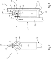
figures 2 and 3 are respectively front and side enlarged views of the hydrogen discharge system offigure 1 ; -
figures 4, 6, 8 and 10 are schematic front side views of the truck offigure 1 , represented in four different configurations occurring when the truck rolls over; and -
figures 5, 7, 9 and 11 represent front views of the hydrogen discharge system in the configurations offigures 4, 6, 8 and 10 respectively. -
Figure 1 represents atruck 2 which is, in the example, a heavy-duty vehicle comprising acab 4 and abody 6. In the example, thebody 6 of thetruck 2, which can also be referred to as the superstructure or the bodywork, is a trailer but one may envisage many different types of truck body, such a as refuse collector, a collecting container, etc. More generally, thebody 6 of the truck designates the structure behind thecab 4, i.e. the structure that is supported or towed by the tractor truck from which the cab is part of. - Alternatively, the
truck 2 may obviously be different from that represented onfigure 1 . In the meaning of the present paper, the term "truck" broadly covers light-duty, medium-duty and heavy-duty vehicles. In other words, any road vehicle, except passengers cars, can be assimilated to a truck. In particular, the truck may be a vacuum truck, a street sweeper, etc. - The
truck 2 is a fuel cell vehicle, meaning that it uses hydrogen fuel cells as a source of power. With this respect, thetruck 2 includes ahydrogen vessel 10, which is, in the example, mounted on thechassis 12 of the tractor unit. Nevertheless, thehydrogen vessel 10 may be placed otherwise, for example in thespace 8 between thecab 4 andbody 6. Besides, in practice, thetruck 2 is preferably equipped with a plurality of hydrogen vessels. The hydrogen vessel is provided with a Pressure Relief Device (PRD) (not shown) for releasing compressed hydrogen in case of emergency, for example in case of an accident. In particular, the PRD automatically opens when the temperature and/or the pressure inside thevessel 10 increases over a predetermined threshold. Alternatively, the PRD may be controlled to switch in open configuration when a crash is detected, in a similar manner to airbags. Typically, accelerometers may be used to detect a crash and trigger the switching of the PRD in open configuration when a high deceleration is detected. - The
truck 2 includes ahydrogen discharge system 14 provided downstream of the pressure relief device on the path of hydrogen when hydrogen is released fromvessel 10. Thehydrogen discharge system 14 can be mounted independently on thetruck 2, meaning that thehydrogen discharge system 14 may be considered as a spare part. - The
system 14 cannot be arranged anywhere on the truck. In practice, the most appropriate space for receiving the discharge system is thespace 8 between thecab 4 and thebody 6. Indeed, the cab is not appropriate to route hydrogen pipes as it is often tiltable relative to the chassis and thebody 6 is not of truck Original Equipment Manufacturer (OEM) responsibility and thus not appropriate to route hydrogen pipes. Alternatively, thecab 4 may be fixed relative to the chassis. - Accordingly, the
hydrogen discharge system 14 is advantageously arranged in thespace 8 between thecab 4 and thebody 6. Thissystem 14 is designed for always orienting the jet of hydrogen upwards relative to the ground when thevessel 10 is vented, i.e. when the PRD opens, for example in the event of an accident. - The
system 14 includes apipe 16 comprising a first longitudinal end (not represented) that is connected to the PRD. Thepipe 16 is provided with onedischarge opening 162, which is preferably a radial opening. This means that thedischarge opening 162 is different from the openings provided at the two longitudinal ends of the pipe. In practice, thepipe 16 is provided with a plurality ofradial discharge openings 162, for example regularly distributed on the periphery of the pipe. - Preferably, the
pipe 16 is a pipe elbow comprising afirst pipe portion 160 delimiting thedischarge opening 162 and asecond pipe portion 164 forming a right angle with thefirst pipe portion 160. Thesecond pipe portion 164 is connected to the PRD of thehydrogen vessel 10. - Advantageously, the
system 14 comprises abracket 26 that is secured to thepipe 16. More precisely, thebracket 26 is a L-shaped bracket comprising two parts 26.1 and 26.2 forming together a right angle. The part 26.1 is secured to the secondlongitudinal end 166 of thepipe 16, i.e. to thepipe end 166 opposed to that connected to the PRD. In addition, the part 26.2 of thebracket 26 is secured to thesecond portion 164 of thepipe 16, meaning that there are two different fixation zones. - In the example, the
bracket 26 includes an attachment means 260, for example for attaching thebracket 26 to the chassis of the truck. In particular, the attachment means 260 is arranged on the bracket part 26.2. - The
system 14 further includes adeflector 18, that is rotatably mounted with respect to thepipe 16 and that includes avent 180, or outlet opening, for venting hydrogen exiting through the discharge opening(s) 162 of thepipe 16. The function ofcomponent 18 is to deflect the flow of hydrogen exiting from the discharge opening(s) 162, that is why it is referred to as a deflector. - On
figure 3 , axis X-X denotes the rotation axis of thedeflector 18 relative to thepipe 16. Typically, the axis X-X remains horizontal, even when the vehicle is tilted or rolls over to the side. In other words, axis X-X remains parallel to the ground. Therefore, the rotation axis X-X is parallel to the longitudinal axis X2 of the truck (length direction), meaning that hydrogen is necessarily released in a plane that is perpendicular to the longitudinal direction of the truck and that there is no risk of releasing hydrogen in direction of thecab 4 or of thebody 6. - Advantageously, the
vent 180 has a specific shape designed for reducing the rotational torque arising from the hydrogen discharge jet. Typically, thevent 180 is a radial opening relative to axis X-X. Accordingly, vent 180 extends in a specific direction D1 that is radial to axis X-X, i.e. that is perpendicular to axis X-X and intersecting axis X-X. The same definition is applicable to discharge opening(s) 162. - The
vent 180 is then designed to obtain a hydrogen jet ejected radially with respect to X-X axis. The resulting force applied by the hydrogen jet does not apply any rotational torque. The parallelism of the direction D1 with an axis radial to axis X-X is designed with tight tolerances so that any misalignment of the resulting force will not result in a torque higher than the balancing torque of thecounterweight 22. - In addition, the deflector is made of a resistant material, such as stainless steel, aluminum, composite material, and in particular fibers reinforced composite material, so as to limit deformation(s) of the
vent 180 in the event of a shock. - Preferably, during operation, the
vent 180 is closed off with aremovable plug 20 that prevents from soiling. Theremovable plug 20 is automatically ejected under the hydrogen pressure inside the deflector 19, as illustrated by arrow F1 onfigure 3 . Typically, theplug 20 protects thevent 180 against blockage, e.g. by dirt, ice, and ingress of water. - A balancing
weight 22 is secured to thedeflector 18 for stabilizing thedeflector 18 in a predetermined orientation with respect to the ground, i.e. in a terrestrial reference frame. The balancingweight 22 may be attached to thedeflector 18 or integral with thedeflector 18. In the example, the balancingweight 22 is protected by thebracket 26 so that it can always freely rotate. - Typically, the balancing
weight 22 maintains thedeflector 18 in a configuration wherein thevent 180 is facing upwards with respect to the ground. Accordingly, if thetruck 2 rolls over, thevent 180 of thedeflector 18 remains oriented upwards with respect to the ground, in order to discharge hydrogen upwards relative to the ground. - Therefore, there is no risk of hydrogen release in direction of the ground or on one side of the vehicle. This is in particular visible on
figures 5, 7, 9 and 11 , representing the configuration of thehydrogen discharge system 14 when thetruck 2 rolls over. Typically, it can be seen onfigures 7, 9 and 11 that when thetruck 2 is tilted to the side or up-side-down, thepipe 16 andbracket 26 rotate relative to the ground. However, the balancingweight deflector 18 remains in a configuration wherein thevent 180 is facing upwards with respect to the ground. Accordingly, hydrogen is released upwards, as represented by arrows F0 onfigures 1 ,5, 7, 9 and 11 . - Further, when the
truck 2 is in the configuration offigures 4 and 5 , the attachment means 260 of thesystem 14 is in the axis of the hydrogen discharge jet, which enables to sustain the pressure arising from hydrogen release. In other configurations, typically in the configurations offigures 6, 8 and 10 , the balancingweight 22 is calculated so as to compensate the rotational torque arising from the misalignment between the hydrogen discharge jet and the attachment means 260. - Advantageously, the
system 14 further comprises amechanical stop 28 for preventing the balancingweight 22 from making a full rotation around thepipe 16. Typically, themechanical stop 28 is formed at the free end of the bracket part 26.1. In particular, themechanical stop 28 is integral with thebracket 26. - The
mechanical stop 28 enables preventing the balancingweight 22 from being driven in rotation around the pipe by inertial forces. Typically, the balancingweight 22 shall not make a full rotation around thepipe 16 when thetruck 2 tilts to the side, for example when the vehicle moves on a road with a crossfall, or when the vehicle rolls over (accident). In other words, the balancing weight shall not be caught in perpetual rotation due to inertia. - In the meaning of the present document, an upward direction does not necessarily mean a vertical direction. Typically, an upward direction may be inclined relative to the vertical direction, for example of 45°. Therefore, in the configuration of
figures 10 and 11 , wherein thetruck 2 is completely flipped over, the balancingweight 22 hits themechanical stop 28, and slightly rotate relative to the ground. However, thedeflector 18 remains in a configuration wherein thevent 180 is facing upwards relative to the ground, meaning that hydrogen discharged through thevent 180 does not project to the side of the vehicle or in direction of the ground. It is to be noted that the angle infigure 11 between the hydrogen release direction and the vertical direction could be reduced by modifying the geometry of the balancingweight 22 and/or of themechanical stop 28. Typically, one may reduce the width of the balancingweight 22 or increase the length of the bracket part 26.1. - Preferably, the
deflector 18 is a cylindrical box comprising two opposed through-holes, among which at least one of them, preferably each one of them, receives thepipe 16. - In particular, the
pipe portion 160 extends through the holes of the box, meaning that the discharge opening(s) 162 open(s) inside thedeflector 18, i.e. inside the internal volume of the box forming the deflector 18 (See arrow F2 onfigure 3 ). - The
pipe portion 160 and the holes of thedeflector 18 are of circular shape, enabling thepipe portion 160 to rotate relative to thedeflector 18 around axis X-X. Accordingly,deflector 18 can be compared to some kind of bearing. - Typically, the
system 14 further includesmechanical stops deflector 18, from moving in translation along thepipe 16. - In a non-represented alternative embodiment, a damping member is used to damp the rotation of the
deflector 18 relative to thepipe 16 and avoid excessive oscillation of thevent 180. The damping member is preferably a hydraulic damper, wherein the rotating part is at least partially immersed in an oil sump. This means that, in the example, the balancingweight 22 may be at least partially immersed in an oil sump. Accordingly, the oil provides a resistant torque, whose amplitude may be adjusted by increasing or lowering the oil level inside the oil sump. - The features of the depicted embodiment and non-represented alternative embodiments can be combined together to generate new embodiment(s) of the invention.
Claims (17)
- Hydrogen discharge system (14) for a truck (2), this system comprising :- a pipe (16) provided with at least one discharge opening (162),- a deflector (18), that is rotatably mounted with respect to the pipe and that includes a vent (180), for venting hydrogen exiting through the discharge opening,characterized in that the system further includes a balancing weight (22) secured to the deflector (18), so as to maintain the deflector in a configuration wherein the vent (180) is facing upwards with respect to the ground, in order to always discharge hydrogen upwards relative to the ground.
- Hydrogen discharge system according to claim 1, characterized in that the system further comprises a mechanical stop (28) for preventing the balancing weight (22) from making a full rotation around the pipe (16).
- Hydrogen discharge system according to claim 2, characterized in that the mechanical stop (28) is integral with a bracket (26) of the system.
- Hydrogen discharge system according to claim 1 or 2, characterized in that the discharge opening (162) of the pipe is a radial opening.
- Hydrogen discharge system according to any previous claim, characterized in that the deflector (18) is a cylindrical box comprising two opposed holes, among which at least one of them, preferably each one of them, receives the pipe (16).
- Hydrogen discharge system according to any previous claim, characterized in that the system further comprises a bracket (26) that is secured to the pipe (16).
- Hydrogen discharge system according to previous claim, characterized in that the bracket (26) is secured to a longitudinal end of the pipe.
- Hydrogen discharge system according to claim 6 or 7, characterized in that the pipe (16) is a pipe elbow comprising a first pipe portion (160) delimiting the discharge opening (162) and a second pipe portion (164) forming a right angle with the first pipe portion and in that the bracket (26) is secured to the second pipe portion (164) of the pipe (16).
- Hydrogen discharge system according to any one of the claims 6 to 8, characterized in that the bracket (26) is L-shaped.
- Hydrogen discharge system according to any previous claim, characterized in that the vent (180) is closed off with a removable plug (20).
- Hydrogen discharge system according to any previous claim, characterized in that the system further includes mechanical stops (24a, 24b) for preventing the deflector (18) from moving along the pipe.
- Hydrogen discharge system according to any previous claim, characterized in that the system further includes a damping member for damping the rotation movement of the deflector (18) relative to the pipe (16).
- Hydrogen discharge system according to any previous claim, characterized in that the vent (180) extends radially with respect to a rotation axis (X-X) of the deflector (18).
- Truck (2) comprising a hydrogen discharge system (14) according to any previous claim.
- Truck according to previous claim, characterized in that the truck includes a hydrogen vessel (10), provided with a pressure relief device that is connected at one end of the pipe (16).
- Truck according to claim 14 or 15, characterized in that the truck includes a cab (4) and a body (6) and in that the hydrogen discharge system (14) is arranged between the cab and the body.
- Truck according to any one of the claims 14 to 16, characterized in that a rotation axis (X-X) of the deflector (18) relative to the pipe (16) is parallel to a longitudinal axis (X2) of the truck.
Applications Claiming Priority (1)
| Application Number | Priority Date | Filing Date | Title |
|---|---|---|---|
| PCT/EP2017/075862 WO2019072382A1 (en) | 2017-10-10 | 2017-10-10 | Hydrogen discharge system for a truck and truck comprising such system |
Publications (2)
| Publication Number | Publication Date |
|---|---|
| EP3695159A1 EP3695159A1 (en) | 2020-08-19 |
| EP3695159B1 true EP3695159B1 (en) | 2021-11-03 |
Family
ID=60190801
Family Applications (1)
| Application Number | Title | Priority Date | Filing Date |
|---|---|---|---|
| EP17791298.7A Active EP3695159B1 (en) | 2017-10-10 | 2017-10-10 | Hydrogen discharge system for a truck and truck comprising such system |
Country Status (4)
| Country | Link |
|---|---|
| US (1) | US11598486B2 (en) |
| EP (1) | EP3695159B1 (en) |
| CN (1) | CN111213004B (en) |
| WO (1) | WO2019072382A1 (en) |
Families Citing this family (3)
| Publication number | Priority date | Publication date | Assignee | Title |
|---|---|---|---|---|
| US11491894B2 (en) * | 2018-05-18 | 2022-11-08 | Anderson Industries, Llc | Vehicle power plant to conserve water |
| DE102021202696A1 (en) * | 2021-03-19 | 2022-09-22 | Robert Bosch Gesellschaft mit beschränkter Haftung | Tank device for storing gas fuel for a vehicle and method for operating a tank device for storing gas fuel for a vehicle |
| JP7760347B2 (en) * | 2021-11-29 | 2025-10-27 | ダイムラー トラック エージー | fuel cell vehicle |
Family Cites Families (18)
| Publication number | Priority date | Publication date | Assignee | Title |
|---|---|---|---|---|
| US1393825A (en) * | 1920-07-21 | 1921-10-18 | Porharty Fredrick | Valve for rotating drums |
| US1511162A (en) * | 1921-10-10 | 1924-10-07 | Martin Hussey | Automatic control for intake passages |
| US2089640A (en) * | 1933-07-08 | 1937-08-10 | Bessie D Apple | Pendulum valve |
| US2433405A (en) * | 1944-06-05 | 1947-12-30 | Benjamin I J Stamm | Safety gravity controlled valve |
| US2460159A (en) * | 1945-04-19 | 1949-01-25 | Southern Steel Co | Vapor outlet for truck tanks |
| JPS51132557A (en) * | 1975-05-14 | 1976-11-17 | Honda Motor Co Ltd | Device for preventing fuel from leaking when vehicle is overturned |
| DE2748692C2 (en) * | 1977-10-29 | 1983-04-07 | MTU Motoren- und Turbinen-Union München GmbH, 8000 München | Aircraft gravity flow control valve |
| JP2004136828A (en) * | 2002-10-18 | 2004-05-13 | Nissan Motor Co Ltd | High pressure gas storage device |
| JP2007106262A (en) | 2005-10-13 | 2007-04-26 | Mazda Motor Corp | Gas fuel tank structure for vehicles |
| JP4874948B2 (en) | 2007-12-28 | 2012-02-15 | トヨタ自動車株式会社 | Safety valve device, valve device, high-pressure gas tank, and vehicle |
| US20110288738A1 (en) * | 2010-04-19 | 2011-11-24 | Icr Turbine Engine Corporation | Multi-fuel vehicle strategy |
| JP5440452B2 (en) * | 2010-08-31 | 2014-03-12 | スズキ株式会社 | Fuel cell system |
| JP5637392B2 (en) * | 2011-04-06 | 2014-12-10 | スズキ株式会社 | Exhaust device for fuel cell vehicle |
| JP6119429B2 (en) | 2013-05-29 | 2017-04-26 | スズキ株式会社 | Fluid discharge device |
| WO2015195001A2 (en) * | 2014-06-18 | 2015-12-23 | Volvo Truck Corporation | Safety arrangement for a vehicle tank |
| US9682618B2 (en) | 2015-02-05 | 2017-06-20 | Agility Fuel Systems Llc | Manual emergency gas release system |
| DE102015015004A1 (en) | 2015-11-19 | 2017-05-24 | Daimler Ag | valve means |
| SE539829C2 (en) * | 2016-04-26 | 2017-12-12 | Scania Cv Ab | LNG truck and method for assembling an LNG truck |
-
2017
- 2017-10-10 CN CN201780095771.5A patent/CN111213004B/en active Active
- 2017-10-10 WO PCT/EP2017/075862 patent/WO2019072382A1/en not_active Ceased
- 2017-10-10 EP EP17791298.7A patent/EP3695159B1/en active Active
- 2017-10-10 US US16/754,428 patent/US11598486B2/en active Active
Also Published As
| Publication number | Publication date |
|---|---|
| CN111213004A (en) | 2020-05-29 |
| EP3695159A1 (en) | 2020-08-19 |
| US11598486B2 (en) | 2023-03-07 |
| US20200340624A1 (en) | 2020-10-29 |
| WO2019072382A1 (en) | 2019-04-18 |
| CN111213004B (en) | 2021-09-24 |
Similar Documents
| Publication | Publication Date | Title |
|---|---|---|
| JP4549826B2 (en) | Fuel cell vehicle | |
| EP3695159B1 (en) | Hydrogen discharge system for a truck and truck comprising such system | |
| US9216647B2 (en) | Vehicle fuel tank system for improved crashworthiness | |
| JP2017144926A (en) | Vehicle with gas tank | |
| CN110416447A (en) | Vehicular battery shell | |
| JP5382494B2 (en) | Canister mounting structure | |
| US20110139534A1 (en) | Motor vehicle and body floor structure for a motor vehicle | |
| US10343833B2 (en) | Vehicle fuel tank for improved crashworthiness | |
| US20230241966A1 (en) | Machine | |
| JP2019172009A (en) | Fuel tank protection structure | |
| AU2012331437B2 (en) | Armoured, mine-endangered vehicle | |
| US7216893B2 (en) | Airbag apparatus, motorcycle with airbag apparatus | |
| JP7790881B2 (en) | Excavator | |
| JP2006137233A (en) | High pressure fuel gas tank fixing system | |
| AU2024294611A1 (en) | Utility vehicle | |
| WO2025186974A1 (en) | Arrangement structure of electronic component for vehicle | |
| JP5036395B2 (en) | Canister mounting structure | |
| KR200157191Y1 (en) | A structure of canister mounting for an automobile | |
| JP2025151775A (en) | Protective structure for in-vehicle components | |
| FR2890354A1 (en) | Shock-absorbing system for protecting interior of vehicle in collision comprises air bag mounted between bulkhead and engine block | |
| WO2025083950A1 (en) | Vehicle and tank cover | |
| JP2015013559A (en) | Tire mounting structure in vehicle storage space | |
| KR100482073B1 (en) | Separated type spare tire container in vehicle | |
| CN204210417U (en) | Truck | |
| KR19990010850A (en) | Vehicle rear floor structure |
Legal Events
| Date | Code | Title | Description |
|---|---|---|---|
| STAA | Information on the status of an ep patent application or granted ep patent |
Free format text: STATUS: UNKNOWN |
|
| STAA | Information on the status of an ep patent application or granted ep patent |
Free format text: STATUS: THE INTERNATIONAL PUBLICATION HAS BEEN MADE |
|
| PUAI | Public reference made under article 153(3) epc to a published international application that has entered the european phase |
Free format text: ORIGINAL CODE: 0009012 |
|
| STAA | Information on the status of an ep patent application or granted ep patent |
Free format text: STATUS: REQUEST FOR EXAMINATION WAS MADE |
|
| 17P | Request for examination filed |
Effective date: 20200323 |
|
| AK | Designated contracting states |
Kind code of ref document: A1 Designated state(s): AL AT BE BG CH CY CZ DE DK EE ES FI FR GB GR HR HU IE IS IT LI LT LU LV MC MK MT NL NO PL PT RO RS SE SI SK SM TR |
|
| AX | Request for extension of the european patent |
Extension state: BA ME |
|
| DAV | Request for validation of the european patent (deleted) | ||
| DAX | Request for extension of the european patent (deleted) | ||
| GRAP | Despatch of communication of intention to grant a patent |
Free format text: ORIGINAL CODE: EPIDOSNIGR1 |
|
| STAA | Information on the status of an ep patent application or granted ep patent |
Free format text: STATUS: GRANT OF PATENT IS INTENDED |
|
| INTG | Intention to grant announced |
Effective date: 20210616 |
|
| GRAS | Grant fee paid |
Free format text: ORIGINAL CODE: EPIDOSNIGR3 |
|
| GRAA | (expected) grant |
Free format text: ORIGINAL CODE: 0009210 |
|
| STAA | Information on the status of an ep patent application or granted ep patent |
Free format text: STATUS: THE PATENT HAS BEEN GRANTED |
|
| AK | Designated contracting states |
Kind code of ref document: B1 Designated state(s): AL AT BE BG CH CY CZ DE DK EE ES FI FR GB GR HR HU IE IS IT LI LT LU LV MC MK MT NL NO PL PT RO RS SE SI SK SM TR |
|
| REG | Reference to a national code |
Ref country code: GB Ref legal event code: FG4D |
|
| REG | Reference to a national code |
Ref country code: AT Ref legal event code: REF Ref document number: 1444258 Country of ref document: AT Kind code of ref document: T Effective date: 20211115 Ref country code: CH Ref legal event code: EP |
|
| REG | Reference to a national code |
Ref country code: IE Ref legal event code: FG4D |
|
| REG | Reference to a national code |
Ref country code: DE Ref legal event code: R096 Ref document number: 602017048786 Country of ref document: DE |
|
| REG | Reference to a national code |
Ref country code: SE Ref legal event code: TRGR |
|
| REG | Reference to a national code |
Ref country code: LT Ref legal event code: MG9D |
|
| REG | Reference to a national code |
Ref country code: NL Ref legal event code: MP Effective date: 20211103 |
|
| REG | Reference to a national code |
Ref country code: AT Ref legal event code: MK05 Ref document number: 1444258 Country of ref document: AT Kind code of ref document: T Effective date: 20211103 |
|
| PG25 | Lapsed in a contracting state [announced via postgrant information from national office to epo] |
Ref country code: RS Free format text: LAPSE BECAUSE OF FAILURE TO SUBMIT A TRANSLATION OF THE DESCRIPTION OR TO PAY THE FEE WITHIN THE PRESCRIBED TIME-LIMIT Effective date: 20211103 Ref country code: LT Free format text: LAPSE BECAUSE OF FAILURE TO SUBMIT A TRANSLATION OF THE DESCRIPTION OR TO PAY THE FEE WITHIN THE PRESCRIBED TIME-LIMIT Effective date: 20211103 Ref country code: FI Free format text: LAPSE BECAUSE OF FAILURE TO SUBMIT A TRANSLATION OF THE DESCRIPTION OR TO PAY THE FEE WITHIN THE PRESCRIBED TIME-LIMIT Effective date: 20211103 Ref country code: BG Free format text: LAPSE BECAUSE OF FAILURE TO SUBMIT A TRANSLATION OF THE DESCRIPTION OR TO PAY THE FEE WITHIN THE PRESCRIBED TIME-LIMIT Effective date: 20220203 Ref country code: AT Free format text: LAPSE BECAUSE OF FAILURE TO SUBMIT A TRANSLATION OF THE DESCRIPTION OR TO PAY THE FEE WITHIN THE PRESCRIBED TIME-LIMIT Effective date: 20211103 |
|
| PG25 | Lapsed in a contracting state [announced via postgrant information from national office to epo] |
Ref country code: IS Free format text: LAPSE BECAUSE OF FAILURE TO SUBMIT A TRANSLATION OF THE DESCRIPTION OR TO PAY THE FEE WITHIN THE PRESCRIBED TIME-LIMIT Effective date: 20220303 Ref country code: PT Free format text: LAPSE BECAUSE OF FAILURE TO SUBMIT A TRANSLATION OF THE DESCRIPTION OR TO PAY THE FEE WITHIN THE PRESCRIBED TIME-LIMIT Effective date: 20220303 Ref country code: PL Free format text: LAPSE BECAUSE OF FAILURE TO SUBMIT A TRANSLATION OF THE DESCRIPTION OR TO PAY THE FEE WITHIN THE PRESCRIBED TIME-LIMIT Effective date: 20211103 Ref country code: NO Free format text: LAPSE BECAUSE OF FAILURE TO SUBMIT A TRANSLATION OF THE DESCRIPTION OR TO PAY THE FEE WITHIN THE PRESCRIBED TIME-LIMIT Effective date: 20220203 Ref country code: NL Free format text: LAPSE BECAUSE OF FAILURE TO SUBMIT A TRANSLATION OF THE DESCRIPTION OR TO PAY THE FEE WITHIN THE PRESCRIBED TIME-LIMIT Effective date: 20211103 Ref country code: LV Free format text: LAPSE BECAUSE OF FAILURE TO SUBMIT A TRANSLATION OF THE DESCRIPTION OR TO PAY THE FEE WITHIN THE PRESCRIBED TIME-LIMIT Effective date: 20211103 Ref country code: HR Free format text: LAPSE BECAUSE OF FAILURE TO SUBMIT A TRANSLATION OF THE DESCRIPTION OR TO PAY THE FEE WITHIN THE PRESCRIBED TIME-LIMIT Effective date: 20211103 Ref country code: GR Free format text: LAPSE BECAUSE OF FAILURE TO SUBMIT A TRANSLATION OF THE DESCRIPTION OR TO PAY THE FEE WITHIN THE PRESCRIBED TIME-LIMIT Effective date: 20220204 Ref country code: ES Free format text: LAPSE BECAUSE OF FAILURE TO SUBMIT A TRANSLATION OF THE DESCRIPTION OR TO PAY THE FEE WITHIN THE PRESCRIBED TIME-LIMIT Effective date: 20211103 |
|
| PG25 | Lapsed in a contracting state [announced via postgrant information from national office to epo] |
Ref country code: SM Free format text: LAPSE BECAUSE OF FAILURE TO SUBMIT A TRANSLATION OF THE DESCRIPTION OR TO PAY THE FEE WITHIN THE PRESCRIBED TIME-LIMIT Effective date: 20211103 Ref country code: SK Free format text: LAPSE BECAUSE OF FAILURE TO SUBMIT A TRANSLATION OF THE DESCRIPTION OR TO PAY THE FEE WITHIN THE PRESCRIBED TIME-LIMIT Effective date: 20211103 Ref country code: RO Free format text: LAPSE BECAUSE OF FAILURE TO SUBMIT A TRANSLATION OF THE DESCRIPTION OR TO PAY THE FEE WITHIN THE PRESCRIBED TIME-LIMIT Effective date: 20211103 Ref country code: EE Free format text: LAPSE BECAUSE OF FAILURE TO SUBMIT A TRANSLATION OF THE DESCRIPTION OR TO PAY THE FEE WITHIN THE PRESCRIBED TIME-LIMIT Effective date: 20211103 Ref country code: DK Free format text: LAPSE BECAUSE OF FAILURE TO SUBMIT A TRANSLATION OF THE DESCRIPTION OR TO PAY THE FEE WITHIN THE PRESCRIBED TIME-LIMIT Effective date: 20211103 Ref country code: CZ Free format text: LAPSE BECAUSE OF FAILURE TO SUBMIT A TRANSLATION OF THE DESCRIPTION OR TO PAY THE FEE WITHIN THE PRESCRIBED TIME-LIMIT Effective date: 20211103 |
|
| REG | Reference to a national code |
Ref country code: DE Ref legal event code: R097 Ref document number: 602017048786 Country of ref document: DE |
|
| PLBE | No opposition filed within time limit |
Free format text: ORIGINAL CODE: 0009261 |
|
| STAA | Information on the status of an ep patent application or granted ep patent |
Free format text: STATUS: NO OPPOSITION FILED WITHIN TIME LIMIT |
|
| 26N | No opposition filed |
Effective date: 20220804 |
|
| PG25 | Lapsed in a contracting state [announced via postgrant information from national office to epo] |
Ref country code: AL Free format text: LAPSE BECAUSE OF FAILURE TO SUBMIT A TRANSLATION OF THE DESCRIPTION OR TO PAY THE FEE WITHIN THE PRESCRIBED TIME-LIMIT Effective date: 20211103 |
|
| PG25 | Lapsed in a contracting state [announced via postgrant information from national office to epo] |
Ref country code: SI Free format text: LAPSE BECAUSE OF FAILURE TO SUBMIT A TRANSLATION OF THE DESCRIPTION OR TO PAY THE FEE WITHIN THE PRESCRIBED TIME-LIMIT Effective date: 20211103 |
|
| PG25 | Lapsed in a contracting state [announced via postgrant information from national office to epo] |
Ref country code: MC Free format text: LAPSE BECAUSE OF FAILURE TO SUBMIT A TRANSLATION OF THE DESCRIPTION OR TO PAY THE FEE WITHIN THE PRESCRIBED TIME-LIMIT Effective date: 20211103 Ref country code: IT Free format text: LAPSE BECAUSE OF FAILURE TO SUBMIT A TRANSLATION OF THE DESCRIPTION OR TO PAY THE FEE WITHIN THE PRESCRIBED TIME-LIMIT Effective date: 20211103 |
|
| REG | Reference to a national code |
Ref country code: CH Ref legal event code: PL |
|
| REG | Reference to a national code |
Ref country code: BE Ref legal event code: MM Effective date: 20221031 |
|
| GBPC | Gb: european patent ceased through non-payment of renewal fee |
Effective date: 20221010 |
|
| PG25 | Lapsed in a contracting state [announced via postgrant information from national office to epo] |
Ref country code: LU Free format text: LAPSE BECAUSE OF NON-PAYMENT OF DUE FEES Effective date: 20221010 |
|
| PG25 | Lapsed in a contracting state [announced via postgrant information from national office to epo] |
Ref country code: LI Free format text: LAPSE BECAUSE OF NON-PAYMENT OF DUE FEES Effective date: 20221031 Ref country code: CH Free format text: LAPSE BECAUSE OF NON-PAYMENT OF DUE FEES Effective date: 20221031 |
|
| PG25 | Lapsed in a contracting state [announced via postgrant information from national office to epo] |
Ref country code: BE Free format text: LAPSE BECAUSE OF NON-PAYMENT OF DUE FEES Effective date: 20221031 |
|
| PG25 | Lapsed in a contracting state [announced via postgrant information from national office to epo] |
Ref country code: IE Free format text: LAPSE BECAUSE OF NON-PAYMENT OF DUE FEES Effective date: 20221010 Ref country code: GB Free format text: LAPSE BECAUSE OF NON-PAYMENT OF DUE FEES Effective date: 20221010 |
|
| PG25 | Lapsed in a contracting state [announced via postgrant information from national office to epo] |
Ref country code: CY Free format text: LAPSE BECAUSE OF FAILURE TO SUBMIT A TRANSLATION OF THE DESCRIPTION OR TO PAY THE FEE WITHIN THE PRESCRIBED TIME-LIMIT Effective date: 20211103 |
|
| PG25 | Lapsed in a contracting state [announced via postgrant information from national office to epo] |
Ref country code: MK Free format text: LAPSE BECAUSE OF FAILURE TO SUBMIT A TRANSLATION OF THE DESCRIPTION OR TO PAY THE FEE WITHIN THE PRESCRIBED TIME-LIMIT Effective date: 20211103 Ref country code: HU Free format text: LAPSE BECAUSE OF FAILURE TO SUBMIT A TRANSLATION OF THE DESCRIPTION OR TO PAY THE FEE WITHIN THE PRESCRIBED TIME-LIMIT; INVALID AB INITIO Effective date: 20171010 |
|
| PG25 | Lapsed in a contracting state [announced via postgrant information from national office to epo] |
Ref country code: MT Free format text: LAPSE BECAUSE OF FAILURE TO SUBMIT A TRANSLATION OF THE DESCRIPTION OR TO PAY THE FEE WITHIN THE PRESCRIBED TIME-LIMIT Effective date: 20211103 |
|
| PGFP | Annual fee paid to national office [announced via postgrant information from national office to epo] |
Ref country code: FR Payment date: 20241025 Year of fee payment: 8 |
|
| PG25 | Lapsed in a contracting state [announced via postgrant information from national office to epo] |
Ref country code: TR Free format text: LAPSE BECAUSE OF FAILURE TO SUBMIT A TRANSLATION OF THE DESCRIPTION OR TO PAY THE FEE WITHIN THE PRESCRIBED TIME-LIMIT Effective date: 20211103 |
|
| PGFP | Annual fee paid to national office [announced via postgrant information from national office to epo] |
Ref country code: DE Payment date: 20251028 Year of fee payment: 9 |
|
| PGFP | Annual fee paid to national office [announced via postgrant information from national office to epo] |
Ref country code: SE Payment date: 20251024 Year of fee payment: 9 |