EP3695093B1 - Large-gap-seal ("lgs") assembly - Google Patents
Large-gap-seal ("lgs") assembly Download PDFInfo
- Publication number
- EP3695093B1 EP3695093B1 EP18797236.9A EP18797236A EP3695093B1 EP 3695093 B1 EP3695093 B1 EP 3695093B1 EP 18797236 A EP18797236 A EP 18797236A EP 3695093 B1 EP3695093 B1 EP 3695093B1
- Authority
- EP
- European Patent Office
- Prior art keywords
- gap
- segment
- structural
- segments
- elastomer core
- Prior art date
- Legal status (The legal status is an assumption and is not a legal conclusion. Google has not performed a legal analysis and makes no representation as to the accuracy of the status listed.)
- Active
Links
- 229920001971 elastomer Polymers 0.000 claims description 84
- 239000000806 elastomer Substances 0.000 claims description 83
- 238000002955 isolation Methods 0.000 claims description 21
- 230000000295 complement effect Effects 0.000 claims description 3
- 238000001125 extrusion Methods 0.000 description 6
- 230000000712 assembly Effects 0.000 description 5
- 238000000429 assembly Methods 0.000 description 5
- 238000000034 method Methods 0.000 description 4
- 239000000463 material Substances 0.000 description 3
- 229910052751 metal Inorganic materials 0.000 description 3
- 239000002184 metal Substances 0.000 description 3
- 239000002131 composite material Substances 0.000 description 2
- 230000006835 compression Effects 0.000 description 2
- 238000007906 compression Methods 0.000 description 2
- 230000001788 irregular Effects 0.000 description 2
- 239000000314 lubricant Substances 0.000 description 2
- 238000007789 sealing Methods 0.000 description 2
- 229920000049 Carbon (fiber) Polymers 0.000 description 1
- 229910000831 Steel Inorganic materials 0.000 description 1
- 230000003044 adaptive effect Effects 0.000 description 1
- 229910052782 aluminium Inorganic materials 0.000 description 1
- XAGFODPZIPBFFR-UHFFFAOYSA-N aluminium Chemical compound [Al] XAGFODPZIPBFFR-UHFFFAOYSA-N 0.000 description 1
- 239000004917 carbon fiber Substances 0.000 description 1
- 238000010276 construction Methods 0.000 description 1
- 230000008602 contraction Effects 0.000 description 1
- 150000002739 metals Chemical class 0.000 description 1
- VNWKTOKETHGBQD-UHFFFAOYSA-N methane Chemical compound C VNWKTOKETHGBQD-UHFFFAOYSA-N 0.000 description 1
- 229920000642 polymer Polymers 0.000 description 1
- 239000010959 steel Substances 0.000 description 1
Images


Classifications
-
- F—MECHANICAL ENGINEERING; LIGHTING; HEATING; WEAPONS; BLASTING
- F16—ENGINEERING ELEMENTS AND UNITS; GENERAL MEASURES FOR PRODUCING AND MAINTAINING EFFECTIVE FUNCTIONING OF MACHINES OR INSTALLATIONS; THERMAL INSULATION IN GENERAL
- F16L—PIPES; JOINTS OR FITTINGS FOR PIPES; SUPPORTS FOR PIPES, CABLES OR PROTECTIVE TUBING; MEANS FOR THERMAL INSULATION IN GENERAL
- F16L55/00—Devices or appurtenances for use in, or in connection with, pipes or pipe systems
- F16L55/10—Means for stopping flow from or in pipes or hoses
- F16L55/12—Means for stopping flow from or in pipes or hoses by introducing into the pipe a member expandable in situ
- F16L55/128—Means for stopping flow from or in pipes or hoses by introducing into the pipe a member expandable in situ introduced axially into the pipe or hose
- F16L55/1283—Plugging pig
-
- F—MECHANICAL ENGINEERING; LIGHTING; HEATING; WEAPONS; BLASTING
- F16—ENGINEERING ELEMENTS AND UNITS; GENERAL MEASURES FOR PRODUCING AND MAINTAINING EFFECTIVE FUNCTIONING OF MACHINES OR INSTALLATIONS; THERMAL INSULATION IN GENERAL
- F16J—PISTONS; CYLINDERS; SEALINGS
- F16J15/00—Sealings
- F16J15/02—Sealings between relatively-stationary surfaces
- F16J15/021—Sealings between relatively-stationary surfaces with elastic packing
- F16J15/022—Sealings between relatively-stationary surfaces with elastic packing characterised by structure or material
-
- F—MECHANICAL ENGINEERING; LIGHTING; HEATING; WEAPONS; BLASTING
- F16—ENGINEERING ELEMENTS AND UNITS; GENERAL MEASURES FOR PRODUCING AND MAINTAINING EFFECTIVE FUNCTIONING OF MACHINES OR INSTALLATIONS; THERMAL INSULATION IN GENERAL
- F16J—PISTONS; CYLINDERS; SEALINGS
- F16J15/00—Sealings
- F16J15/02—Sealings between relatively-stationary surfaces
- F16J15/021—Sealings between relatively-stationary surfaces with elastic packing
- F16J15/028—Sealings between relatively-stationary surfaces with elastic packing the packing being mechanically expanded against the sealing surface
-
- F—MECHANICAL ENGINEERING; LIGHTING; HEATING; WEAPONS; BLASTING
- F16—ENGINEERING ELEMENTS AND UNITS; GENERAL MEASURES FOR PRODUCING AND MAINTAINING EFFECTIVE FUNCTIONING OF MACHINES OR INSTALLATIONS; THERMAL INSULATION IN GENERAL
- F16J—PISTONS; CYLINDERS; SEALINGS
- F16J15/00—Sealings
- F16J15/02—Sealings between relatively-stationary surfaces
- F16J15/06—Sealings between relatively-stationary surfaces with solid packing compressed between sealing surfaces
- F16J15/068—Sealings between relatively-stationary surfaces with solid packing compressed between sealing surfaces the packing swelling under working conditions
-
- F—MECHANICAL ENGINEERING; LIGHTING; HEATING; WEAPONS; BLASTING
- F16—ENGINEERING ELEMENTS AND UNITS; GENERAL MEASURES FOR PRODUCING AND MAINTAINING EFFECTIVE FUNCTIONING OF MACHINES OR INSTALLATIONS; THERMAL INSULATION IN GENERAL
- F16J—PISTONS; CYLINDERS; SEALINGS
- F16J15/00—Sealings
- F16J15/16—Sealings between relatively-moving surfaces
- F16J15/166—Sealings between relatively-moving surfaces with means to prevent the extrusion of the packing
-
- F—MECHANICAL ENGINEERING; LIGHTING; HEATING; WEAPONS; BLASTING
- F16—ENGINEERING ELEMENTS AND UNITS; GENERAL MEASURES FOR PRODUCING AND MAINTAINING EFFECTIVE FUNCTIONING OF MACHINES OR INSTALLATIONS; THERMAL INSULATION IN GENERAL
- F16J—PISTONS; CYLINDERS; SEALINGS
- F16J15/00—Sealings
- F16J15/16—Sealings between relatively-moving surfaces
- F16J15/18—Sealings between relatively-moving surfaces with stuffing-boxes for elastic or plastic packings
- F16J15/20—Packing materials therefor
-
- F—MECHANICAL ENGINEERING; LIGHTING; HEATING; WEAPONS; BLASTING
- F16—ENGINEERING ELEMENTS AND UNITS; GENERAL MEASURES FOR PRODUCING AND MAINTAINING EFFECTIVE FUNCTIONING OF MACHINES OR INSTALLATIONS; THERMAL INSULATION IN GENERAL
- F16J—PISTONS; CYLINDERS; SEALINGS
- F16J15/00—Sealings
- F16J15/46—Sealings with packing ring expanded or pressed into place by fluid pressure, e.g. inflatable packings
-
- F—MECHANICAL ENGINEERING; LIGHTING; HEATING; WEAPONS; BLASTING
- F16—ENGINEERING ELEMENTS AND UNITS; GENERAL MEASURES FOR PRODUCING AND MAINTAINING EFFECTIVE FUNCTIONING OF MACHINES OR INSTALLATIONS; THERMAL INSULATION IN GENERAL
- F16L—PIPES; JOINTS OR FITTINGS FOR PIPES; SUPPORTS FOR PIPES, CABLES OR PROTECTIVE TUBING; MEANS FOR THERMAL INSULATION IN GENERAL
- F16L55/00—Devices or appurtenances for use in, or in connection with, pipes or pipe systems
- F16L55/10—Means for stopping flow from or in pipes or hoses
- F16L55/12—Means for stopping flow from or in pipes or hoses by introducing into the pipe a member expandable in situ
- F16L55/128—Means for stopping flow from or in pipes or hoses by introducing into the pipe a member expandable in situ introduced axially into the pipe or hose
- F16L55/132—Means for stopping flow from or in pipes or hoses by introducing into the pipe a member expandable in situ introduced axially into the pipe or hose the closure device being a plug fixed by radially deforming the packing
-
- F—MECHANICAL ENGINEERING; LIGHTING; HEATING; WEAPONS; BLASTING
- F16—ENGINEERING ELEMENTS AND UNITS; GENERAL MEASURES FOR PRODUCING AND MAINTAINING EFFECTIVE FUNCTIONING OF MACHINES OR INSTALLATIONS; THERMAL INSULATION IN GENERAL
- F16L—PIPES; JOINTS OR FITTINGS FOR PIPES; SUPPORTS FOR PIPES, CABLES OR PROTECTIVE TUBING; MEANS FOR THERMAL INSULATION IN GENERAL
- F16L55/00—Devices or appurtenances for use in, or in connection with, pipes or pipe systems
- F16L55/26—Pigs or moles, i.e. devices movable in a pipe or conduit with or without self-contained propulsion means
- F16L55/28—Constructional aspects
- F16L55/40—Constructional aspects of the body
- F16L55/44—Constructional aspects of the body expandable
-
- E—FIXED CONSTRUCTIONS
- E21—EARTH OR ROCK DRILLING; MINING
- E21B—EARTH OR ROCK DRILLING; OBTAINING OIL, GAS, WATER, SOLUBLE OR MELTABLE MATERIALS OR A SLURRY OF MINERALS FROM WELLS
- E21B33/00—Sealing or packing boreholes or wells
- E21B33/10—Sealing or packing boreholes or wells in the borehole
- E21B33/12—Packers; Plugs
-
- F—MECHANICAL ENGINEERING; LIGHTING; HEATING; WEAPONS; BLASTING
- F16—ENGINEERING ELEMENTS AND UNITS; GENERAL MEASURES FOR PRODUCING AND MAINTAINING EFFECTIVE FUNCTIONING OF MACHINES OR INSTALLATIONS; THERMAL INSULATION IN GENERAL
- F16J—PISTONS; CYLINDERS; SEALINGS
- F16J15/00—Sealings
- F16J15/002—Sealings comprising at least two sealings in succession
Definitions
- This disclosure relates generally to piggable or free floating isolation tools for pipe inline services. More specifically, the disclosure relates to elastomer packer seals for pipeline isolation of oil and gas.
- Elastomer packer seals generally have an elastomer core in the shape of a ring.
- conventional seals use an adaptive spring to close the clearance gap between the plug and the pipeline.
- the spring may become unstable and can fail to support the elastomer core, particularly when the extrusion gap is large and the isolation pressure is high.
- Embodiments of a large-gap-seal (“LGS") assembly for a piggable isolation tool include multiple gap segments that are located on each sidewall of the elastomer core and spaced apart from each other.
- the LGS assembly also includes structural segments located above the gap segments. Each structural segment adjoins the adjacent structural segments along their opposing longitudinal edges when the elastomer core is inactive. Each gap segment is positioned on the elastomer core so that its longitudinal centerline lies approximately below the opposing longitudinal edges of adjacent structural segments.
- a piggable isolation tool for a pipeline includes two or more large-gap-seal (LGS) assemblies.
- Each LGS assembly has multiple spaced-apart gap segments located on each sidewall of the elastomer core and multiple structural segments located above the gap segments.
- LGS large-gap-seal
- the longitudinal centerline of each gap segment is approximately centered beneath opposing longitudinal edges of adjacent structural segments.
- the adjacent structural segments move apart, exposing the gap segments.
- a method of deploying an LGS assembly having an elastomer core, gap segments on each sidewall of the elastomer core, and structural segments above the gap segments is also described.
- the method includes placing the LGS assembly at a selected location within a pipeline and pressurizing the elastomer core. This creates spaces between the opposing longitudinal edges of adjacent structural segments and exposes the gap segments.
- This disclosure describes a dynamic mechanical support structure that can support and close the spaces through which the elastomer core can escape when the LGS assembly is activated and the elastomer core is pressurized, thereby protecting the integrity of the elastomer core and ensuring a safe and reliable seal between the isolation tool and the inner wall of the pipeline.
- advantages of the disclosure may include: (a) using a softer rubber (such as 33-50 Shore A) for the elastomer core, which improves the sealing capabilities in rough or irregular pipelines; (b) supporting large extrusion gaps between the end of the tool body and the inner diameter of the pipeline, thereby allowing the use of a smaller plug with reduced risk of becoming stuck in the pipeline; (c) combining large extrusion gaps with high pressure isolations; (d) allowing the isolation tool to operate at higher pressures and/or higher expansions than conventional tools; (e) using one isolation tool to cover a greater range of pipeline sizes than conventional tools; and (f) enabling the reuse of structural segments when the elastomer core must be replaced.
- a softer rubber such as 33-50 Shore A
- embodiments of a piggable isolation tool 20 have slips 25 which grip the inner wall of the pipeline and one or more large-gap seal (“LGS") assemblies 30.
- LGS large-gap seal
- the LGS assembly 30 holds the elastomer core 50 of the assembly 30 against the inner wall of the pipeline P, creating a seal and isolating that portion of the pipeline.
- the isolation tool 20 may be comprised of multiple LGS assemblies 30.
- the LGS assembly 30 is comprised of an inner elastomer core 50, gap segments 60, structural segments 70, and plug pressure heads 40.
- the material and profile of each component may vary depending upon the desired application. As an example, for applications with very high pressure, the structural segments and gap segments may be designed with stronger materials and profile types that close any spaces where the elastomer may escape.
- the elastomer core 50 may be an elastomer suited for the application requirements, including but not limited to NBR-50Shore A.
- the outside diameter edge 57 of the elastomer core 50 seals against the inner wall of the pipeline, while the inside diameter edge 53 of the elastomer core 50 seals against the packer support ring (not shown).
- Each sidewall 55 of the elastomer core 50 is covered by a plug pressure head 40.
- the elastomer core 50 may be divided into two or more separate rings to help regulate the amount of stress on the core 50 and to improve its performance.
- the elastomer core 50 may have an inner ring 51 surrounded by an outer ring 52.
- Structural segments 70 which include a core face surface 71 complementary in shape to the profile of the opposing sidewall 55 of the elastomer core 50 and extend in a v-like shape from the inside diameter edge 53 to the outside diameter edge 57 of the elastomer core 50, are located between the elastomer core 50 and each plug pressure head 40.
- Structural segments 70 may be made of aluminum, steel, or a composite material including but not limited to carbon fiber, cell material, reinforced polymers, or metals.
- Glide plates 80 which facilitate the movement of structural segments 70 when the LGS assembly 30 is deployed or retracted, may be located between the structural segments 70 and each plug pressure head 40.
- Each glide plate 80 may be associated with one structural segment 70 and connected to the plug pressure head face surface 73 of the structural segment 70. Depending on the characteristics of the structural segments 70, glide plates 80 may not be required.
- tabs or slots may be used to control the position of the structural segments 70 when they are moving outward or inward with the elastomer core 50.
- guide slots 90 on the plug pressure head 40 may receive guide tabs 95 on the glide plates 80 in order to maintain the desired angle when the LGS assembly 30 is being deployed.
- guide slots on the glide plate may receive guide tabs on the plug pressure head.
- guide pockets 100 on the structural segments 70 may receive guide pins 105 on the gap segments 60.
- the guide pins 105 may be located on the structural segments 70 and the guide pockets 100 may be located on the gap segments 60.
- the guide pockets 100 and guide pins 105 may further assist in controlling the spacing between the gap segments 60 and structural segments 70 and in maintaining the desired angle during expansion of the elastomer core 50 and deployment of the LGS assembly 30.
- a seal return spring 110 may be placed inside each structural segment 70, as shown in FIG. 9 , or on top of each structural segment 70.
- the seal return spring 110 makes the LGS assembly 30 more robust by increasing the strength of the compression force, keeping the structural segments 70 connected and centered to the isolation tool 20 during pigging and unsetting, preventing the structural segments 70 from extending beyond the body of the LGS assembly 30, and preventing damaged structural segments 70 from falling apart.
- seal return springs 110 may be particularly useful for applications that have a long duration and/or where the isolation tool 20 must be transported (pigged) over long distances inside the pipeline.
- Design alternatives for the seal return spring 110 may include, but are not limited to, a hooped spring that encompasses all of the structural segments 70 in a particular layer and an integrated tension spring located inside each structural segment 70.
- Gap segments 60 which are located on the sidewalls 55 of the elastomer core 50 and underneath the structural segments 70, are spaced apart from one another and generally centered beneath the points where adjacent structural segments 70 meet. In other words, the approximate longitudinal centerline 65 of the gap segment 60 is aligned with the adjoining longitudinal edges 75 of two adjacent structural segments 70.
- Each gap segment 60 has a core face surface 61 that is complementary in shape to the profile of the opposing sidewall 55 of the elastomer core 50, extends from the inside diameter edge 53 to the outside diameter edge 57 of the elastomer core 50, and is in contact with the elastomer core 50.
- Gap segments 60 may be made of metal, and are preferably made of metal/composite with low friction toward sliding parts, i.e., a friction coefficient ranging from approximately 0.1 to approximately 0.2. They can be rectangular or v-shaped, as shown in FIG. 4 , and may have a height (thickness) that is less than the height of the structural segments 70.
- the surface between the elastomer core 50 and the core face surface 61 of the gap segments 60 may be lubricated to reduce friction.
- the plug pressure head face surface 63 of the gap segments 60 which is in contact with the structural segments 70, may also be lubricated to reduce friction.
- an overlapping flexible lip 120 may be added to the gap segments 60 to prevent the elastomer core 50 from protruding into the spaces that may form between the outside diameter edge 67 of the gap segment 60 and the inner pipeline wall when the pipeline wall is irregular and/or partially occluded.
- an overlapping flexible lip 125 may be added to the structural segments 70 to protect the elastomer core 50.
- the ratio of structural segments 70 to gap segments 60, and the space between gap segments 60 depends on the application where the LGS assembly 30 will be used.
- the portion of the sidewall 55 of the elastomer core 50 that is covered by gap segment 60 may be defined by an inside and outside diameter arc of 360°/2N, where N is the number of gap segments 60.
- the portion of the sidewall 55 that is covered by structural segment 70 may be defined by an arc of 360°/M, where M is the number of structural segments 70.
- twelve structural segments 70 may be used on each sidewall 55 of the elastomer core 50.
- the twelve structural segments 70 cover the respective sidewall 55 of the elastomer core 50, forming twelve sets of adjoining longitudinal edges 75.
- a gap segment 60 is located beneath each set of adjoining longitudinal edges 75.
- Each gap segment 60 may be sized to span or cover a portion of the sidewall 55 of the elastomer core 50 that is approximately half the size as that covered by each structural segment 70.
- each gap segment 60 covers an arc of approximately 15° at the inside diameter edge 53 of the elastomer core 50 to an arc of approximately 15° at the outside diameter edge 57 of the elastomer core 50.
- the longitudinal centerline 65 of each gap segment 60 is approximately 30° from the longitudinal centerline 65 of the adjacent gap segment 60.
- Each structural segment 70 may be sized to span the portion of the sidewall 55 of the elastomer core 50 that is defined by an arc of approximately 30° at the inside diameter edge 53 of the elastomer core 50 to an arc of approximately 30° at the outside diameter edge 57 of the elastomer core 50.
- the steps in assembling the LGS assembly 30 are shown in the exploded view of FIG. 5 .
- the plug pressure head 40 is prepared for assembly by adding lubricants, such as low friction paste, on the surface of the plug pressure head 40 that will receive the structural segments 70.
- the first layer of structural segments 70 is positioned on the plug pressure head 40 and around the packer support ring.
- the first layer of gap segments 60 is placed on the structural segments 70 so that the longitudinal centerline 65 of each gap segment 60 is approximately aligned with the adjoining longitudinal edges 75 of adjacent structural segments 70.
- the elastomer core 50 is then placed on top of the first layer of structural segments 70 and the first layer of gap segments 60.
- the second layer of gap segments 60 followed by the second layer of structural segments 70, is positioned around the packer support ring and on top of the elastomer core 50.
- the second layer of gap segments 60 is positioned so that each gap segment 60 is approximately centered beneath the adjoining longitudinal edges 75 of adjacent structural segments 70.
- Lubricants may be added between the elastomer core 50, the gap segments 60, and/or the structural segments 70 to control the gliding friction.
- the second plug pressure head 40, or bowl is placed on top of the second layer of structural segments 70 to complete the LGS assembly 30.
- the seal is activated by compressing the isolation tool 20.
- Such pressurization causes the elastomer core 50 to expand by allowing the structural segments 70 (and the associated glide plates 80, if present) to slide outwards toward the pipeline wall.
- the movement of the structural segments 70 causes the space between adjacent longitudinal edges 75 of the structural segments 70 to increase.
- the spaces increase, they expose the gap segments 60 on the elastomer core 50, which are sized to be larger than the span of the space between the structural segments 70.
- the LGS assembly 30 is fully activated, the transformed and pressurized elastomer core 50 cannot escape into the spaces between structural segments 70.
- the elastomer core 50 is protected from damage and the integrity of the seal against the pipeline wall is preserved.
- the gap segments 60 and the structural segments 70 continue to move until they contact the inside wall of the pipeline. Further compression of the LGS assembly 30 activates the seal between sections of the pipeline. The delta pressure ("DP") over the seal may then be increased, with the pressure inside the seal remaining higher than the DP.
- DP delta pressure
- the elastomer core 50 contracts due to elastomer "memory", which returns the structural segments 70 and gap segments 60 to their original positions. This contraction may be further enabled by the profile of the gap segments 60 and structural segments 70 and the friction between them.
- the LGS assembly 30 may be set and unset at operating pressures ranging from zero to several hundred bar, depending upon the desired design parameter. The strength of the structural segments 70 and the gap segments 60 will determine the maximum pipeline pressure the LGS assembly 30 can support.
Landscapes
- Engineering & Computer Science (AREA)
- General Engineering & Computer Science (AREA)
- Mechanical Engineering (AREA)
- Physics & Mathematics (AREA)
- Architecture (AREA)
- Fluid Mechanics (AREA)
- Chemical & Material Sciences (AREA)
- Combustion & Propulsion (AREA)
- Gasket Seals (AREA)
- Pipe Accessories (AREA)
Description
- This disclosure relates generally to piggable or free floating isolation tools for pipe inline services. More specifically, the disclosure relates to elastomer packer seals for pipeline isolation of oil and gas.
- Elastomer packer seals generally have an elastomer core in the shape of a ring. In an effort to alleviate the sealing problem of high extrusion gap, conventional seals use an adaptive spring to close the clearance gap between the plug and the pipeline. However, there are openings between the spring coils. Portions of the elastomer core may protrude through these openings, with the resulting loss of elastomer ("elastomer creep") challenging the integrity of the packer as pressure and/or temperature increase. In addition, the spring may become unstable and can fail to support the elastomer core, particularly when the extrusion gap is large and the isolation pressure is high.
- There is a need for a dynamic mechanical support structure that can support and protect the elastomer core while allowing large extrusion gaps. There is also a need for a dynamic mechanical support structure that can withstand high pressure forces.
- Similar seal assemblies are known from
US4852394A ,CA2494290A1 ,WO2017/127075A , as well asUS2016/376869A1 that discloses a seal assembly according to the preambles of claims 1 and 15. - Embodiments of a large-gap-seal ("LGS") assembly for a piggable isolation tool include multiple gap segments that are located on each sidewall of the elastomer core and spaced apart from each other. The LGS assembly also includes structural segments located above the gap segments. Each structural segment adjoins the adjacent structural segments along their opposing longitudinal edges when the elastomer core is inactive. Each gap segment is positioned on the elastomer core so that its longitudinal centerline lies approximately below the opposing longitudinal edges of adjacent structural segments. When the LGS assembly is activated and the elastomer core expands, causing adjoining structural segments to separate from one another, the gap segments, rather than the elastomer core, are exposed.
- A piggable isolation tool for a pipeline includes two or more large-gap-seal (LGS) assemblies. Each LGS assembly has multiple spaced-apart gap segments located on each sidewall of the elastomer core and multiple structural segments located above the gap segments. When the LGS assembly is in an inactive state, the longitudinal centerline of each gap segment is approximately centered beneath opposing longitudinal edges of adjacent structural segments. When the LGS assembly is fully activated, the adjacent structural segments move apart, exposing the gap segments.
- A method of deploying an LGS assembly having an elastomer core, gap segments on each sidewall of the elastomer core, and structural segments above the gap segments is also described. The method includes placing the LGS assembly at a selected location within a pipeline and pressurizing the elastomer core. This creates spaces between the opposing longitudinal edges of adjacent structural segments and exposes the gap segments.
- This disclosure describes a dynamic mechanical support structure that can support and close the spaces through which the elastomer core can escape when the LGS assembly is activated and the elastomer core is pressurized, thereby protecting the integrity of the elastomer core and ensuring a safe and reliable seal between the isolation tool and the inner wall of the pipeline. Other advantages of the disclosure may include: (a) using a softer rubber (such as 33-50 Shore A) for the elastomer core, which improves the sealing capabilities in rough or irregular pipelines; (b) supporting large extrusion gaps between the end of the tool body and the inner diameter of the pipeline, thereby allowing the use of a smaller plug with reduced risk of becoming stuck in the pipeline; (c) combining large extrusion gaps with high pressure isolations; (d) allowing the isolation tool to operate at higher pressures and/or higher expansions than conventional tools; (e) using one isolation tool to cover a greater range of pipeline sizes than conventional tools; and (f) enabling the reuse of structural segments when the elastomer core must be replaced.
-
-
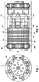
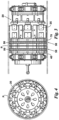
FIG. 1 is an isometric view of an embodiment of a piggable isolation tool, shown in pigging (traveling) mode. -
FIG. 2 is an orthogonal view of an embodiment of a piggable isolation tool, shown in pigging (traveling) mode. -
FIG. 3 is an orthogonal view of an embodiment of a piggable isolation tool, shown in set (deployed) mode. -
FIG. 4 is an orthogonal view of an embodiment of a piggable isolation tool, shown in set (deployed) mode. -
FIG. 5 is an exploded view of an embodiment of the LGS assembly. -
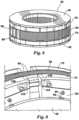
FIG. 6 is an isometric view of an embodiment of the LGS assembly shown inFIG. 5 . -
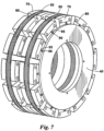
FIG. 7 is an isometric view of an activated seal with two LGS assemblies. -
FIG. 8 is an expanded view of an embodiment of the LGS assembly during deployment of the seal. -
FIG. 9 is a partial cross-section of an embodiment of the LGS assembly, including the seal return spring. -
FIG. 10 is a partial isometric view of an embodiment of the LGS assembly, including overlapping flexible lips on the gap segment and the structural segment. -
- 20
- Piggable isolation tool
- 25
- Slip
- 30
- LGS assembly
- 40
- Plug pressure head
- 50
- Elastomer core
- 51
- Inner ring of elastomer core
- 52
- Outer ring of elastomer core
- 53
- Inside diameter edge
- 55
- Sidewall
- 57
- Outside diameter edge
- 58
- Exposed portion
- 59
- Covered portion
- 60
- Gap segment
- 61
- Core face surface
- 63
- Plug pressure head face surface
- 65
- Longitudinal centerline
- 67
- Outside diameter edge
- 69
- Inside diameter edge
- 70
- Structural segment
- 71
- Core face surface
- 73
- Plug pressure head face surface
- 75
- Longitudinal edge
- 80
- Glide plate
- 90
- Guide slot
- 95
- Guide tab
- 100
- Guide pocket
- 105
- Guide pin
- 110
- Seal return spring
- 120
- Overlapping flexible lip on gap segment
- 125
- Overlapping flexible lip on structural segment
- P
- Pipeline
- Large gap: seal gap extrusion where the ratio of pipeline inner diameter to tool outer diameter is greater than approximately 1.10.
- Referring to
FIGS. 1-10 , embodiments of apiggable isolation tool 20 haveslips 25 which grip the inner wall of the pipeline and one or more large-gap seal ("LGS")assemblies 30. When activated and pressurized, theLGS assembly 30 holds theelastomer core 50 of theassembly 30 against the inner wall of the pipeline P, creating a seal and isolating that portion of the pipeline. Theisolation tool 20 may be comprised ofmultiple LGS assemblies 30. - Referring to
FIGS. 5-7 , theLGS assembly 30 is comprised of aninner elastomer core 50,gap segments 60,structural segments 70, and plug pressure heads 40. The material and profile of each component may vary depending upon the desired application. As an example, for applications with very high pressure, the structural segments and gap segments may be designed with stronger materials and profile types that close any spaces where the elastomer may escape. - The
elastomer core 50 may be an elastomer suited for the application requirements, including but not limited to NBR-50Shore A. Theoutside diameter edge 57 of theelastomer core 50 seals against the inner wall of the pipeline, while theinside diameter edge 53 of theelastomer core 50 seals against the packer support ring (not shown). Eachsidewall 55 of theelastomer core 50 is covered by aplug pressure head 40. Theelastomer core 50 may be divided into two or more separate rings to help regulate the amount of stress on thecore 50 and to improve its performance. For example, as shown inFIG. 5 , theelastomer core 50 may have an inner ring 51 surrounded by anouter ring 52. -
Structural segments 70, which include acore face surface 71 complementary in shape to the profile of the opposingsidewall 55 of theelastomer core 50 and extend in a v-like shape from theinside diameter edge 53 to theoutside diameter edge 57 of theelastomer core 50, are located between theelastomer core 50 and each plugpressure head 40.Structural segments 70 may be made of aluminum, steel, or a composite material including but not limited to carbon fiber, cell material, reinforced polymers, or metals. -
Glide plates 80, which facilitate the movement ofstructural segments 70 when theLGS assembly 30 is deployed or retracted, may be located between thestructural segments 70 and each plugpressure head 40. Eachglide plate 80 may be associated with onestructural segment 70 and connected to the plug pressurehead face surface 73 of thestructural segment 70. Depending on the characteristics of thestructural segments 70,glide plates 80 may not be required. - Referring to
FIG. 7 andFIG. 8 , in addition to thecore face surface 71 of thestructural segments 70, tabs or slots may be used to control the position of thestructural segments 70 when they are moving outward or inward with theelastomer core 50. For example, as shown inFIG. 7 , guideslots 90 on theplug pressure head 40 may receiveguide tabs 95 on theglide plates 80 in order to maintain the desired angle when theLGS assembly 30 is being deployed. As another example, guide slots on the glide plate may receive guide tabs on the plug pressure head. As shown inFIG. 8 , guidepockets 100 on thestructural segments 70 may receive guide pins 105 on thegap segments 60. Alternatively, the guide pins 105 may be located on thestructural segments 70 and the guide pockets 100 may be located on thegap segments 60. The guide pockets 100 and guidepins 105 may further assist in controlling the spacing between thegap segments 60 andstructural segments 70 and in maintaining the desired angle during expansion of theelastomer core 50 and deployment of theLGS assembly 30. - A
seal return spring 110 may be placed inside eachstructural segment 70, as shown inFIG. 9 , or on top of eachstructural segment 70. Theseal return spring 110 makes theLGS assembly 30 more robust by increasing the strength of the compression force, keeping thestructural segments 70 connected and centered to theisolation tool 20 during pigging and unsetting, preventing thestructural segments 70 from extending beyond the body of theLGS assembly 30, and preventing damagedstructural segments 70 from falling apart. For example, seal return springs 110 may be particularly useful for applications that have a long duration and/or where theisolation tool 20 must be transported (pigged) over long distances inside the pipeline. Design alternatives for theseal return spring 110 may include, but are not limited to, a hooped spring that encompasses all of thestructural segments 70 in a particular layer and an integrated tension spring located inside eachstructural segment 70. -
Gap segments 60, which are located on thesidewalls 55 of theelastomer core 50 and underneath thestructural segments 70, are spaced apart from one another and generally centered beneath the points where adjacentstructural segments 70 meet. In other words, the approximatelongitudinal centerline 65 of thegap segment 60 is aligned with the adjoininglongitudinal edges 75 of two adjacentstructural segments 70. Eachgap segment 60 has acore face surface 61 that is complementary in shape to the profile of the opposingsidewall 55 of theelastomer core 50, extends from theinside diameter edge 53 to theoutside diameter edge 57 of theelastomer core 50, and is in contact with theelastomer core 50.Gap segments 60 may be made of metal, and are preferably made of metal/composite with low friction toward sliding parts, i.e., a friction coefficient ranging from approximately 0.1 to approximately 0.2. They can be rectangular or v-shaped, as shown inFIG. 4 , and may have a height (thickness) that is less than the height of thestructural segments 70. - The surface between the
elastomer core 50 and thecore face surface 61 of thegap segments 60 may be lubricated to reduce friction. The plug pressurehead face surface 63 of thegap segments 60, which is in contact with thestructural segments 70, may also be lubricated to reduce friction. As shown inFIG. 10 , an overlappingflexible lip 120 may be added to thegap segments 60 to prevent theelastomer core 50 from protruding into the spaces that may form between theoutside diameter edge 67 of thegap segment 60 and the inner pipeline wall when the pipeline wall is irregular and/or partially occluded. Similarly, an overlappingflexible lip 125 may be added to thestructural segments 70 to protect theelastomer core 50. - The ratio of
structural segments 70 togap segments 60, and the space between gap segments 60 (the "gap size") depends on the application where theLGS assembly 30 will be used. The portion of thesidewall 55 of theelastomer core 50 that is covered bygap segment 60 may be defined by an inside and outside diameter arc of 360°/2N, where N is the number ofgap segments 60. The portion of thesidewall 55 that is covered bystructural segment 70 may be defined by an arc of 360°/M, where M is the number ofstructural segments 70. - As shown as an example in
FIG. 5 , twelvestructural segments 70, along with twelvegap segments 60, may be used on eachsidewall 55 of theelastomer core 50. The twelvestructural segments 70 cover therespective sidewall 55 of theelastomer core 50, forming twelve sets of adjoining longitudinal edges 75. Agap segment 60 is located beneath each set of adjoining longitudinal edges 75. Eachgap segment 60 may be sized to span or cover a portion of thesidewall 55 of theelastomer core 50 that is approximately half the size as that covered by eachstructural segment 70. - If twelve
gap segments 60 are used, eachgap segment 60 covers an arc of approximately 15° at theinside diameter edge 53 of theelastomer core 50 to an arc of approximately 15° at theoutside diameter edge 57 of theelastomer core 50. As a result, thelongitudinal centerline 65 of eachgap segment 60 is approximately 30° from thelongitudinal centerline 65 of theadjacent gap segment 60. When thegap segments 60 are spaced apart from one another in this manner -- and not yet covered by thestructural segments 70 -- there are twelve exposedportions 58 and twelve coveredportions 59 of thesidewall 55, with each portion being approximately equal in size to thegap segments 60. Eachstructural segment 70 may be sized to span the portion of thesidewall 55 of theelastomer core 50 that is defined by an arc of approximately 30° at theinside diameter edge 53 of theelastomer core 50 to an arc of approximately 30° at theoutside diameter edge 57 of theelastomer core 50. - The steps in assembling the
LGS assembly 30 are shown in the exploded view ofFIG. 5 . Theplug pressure head 40 is prepared for assembly by adding lubricants, such as low friction paste, on the surface of theplug pressure head 40 that will receive thestructural segments 70. The first layer ofstructural segments 70 is positioned on theplug pressure head 40 and around the packer support ring. The first layer ofgap segments 60 is placed on thestructural segments 70 so that thelongitudinal centerline 65 of eachgap segment 60 is approximately aligned with the adjoininglongitudinal edges 75 of adjacentstructural segments 70. Theelastomer core 50 is then placed on top of the first layer ofstructural segments 70 and the first layer ofgap segments 60. The second layer ofgap segments 60, followed by the second layer ofstructural segments 70, is positioned around the packer support ring and on top of theelastomer core 50. Once again, the second layer ofgap segments 60 is positioned so that eachgap segment 60 is approximately centered beneath the adjoininglongitudinal edges 75 of adjacentstructural segments 70. Lubricants may be added between theelastomer core 50, thegap segments 60, and/or thestructural segments 70 to control the gliding friction. The secondplug pressure head 40, or bowl, is placed on top of the second layer ofstructural segments 70 to complete theLGS assembly 30. - The seal is activated by compressing the
isolation tool 20. Such pressurization causes theelastomer core 50 to expand by allowing the structural segments 70 (and the associatedglide plates 80, if present) to slide outwards toward the pipeline wall. The movement of thestructural segments 70 causes the space between adjacentlongitudinal edges 75 of thestructural segments 70 to increase. As the spaces increase, they expose thegap segments 60 on theelastomer core 50, which are sized to be larger than the span of the space between thestructural segments 70. As a result, when theLGS assembly 30 is fully activated, the transformed andpressurized elastomer core 50 cannot escape into the spaces betweenstructural segments 70. Theelastomer core 50 is protected from damage and the integrity of the seal against the pipeline wall is preserved. - The
gap segments 60 and thestructural segments 70 continue to move until they contact the inside wall of the pipeline. Further compression of theLGS assembly 30 activates the seal between sections of the pipeline. The delta pressure ("DP") over the seal may then be increased, with the pressure inside the seal remaining higher than the DP. When theLGS assembly 30 is de-pressurized, theelastomer core 50 contracts due to elastomer "memory", which returns thestructural segments 70 andgap segments 60 to their original positions. This contraction may be further enabled by the profile of thegap segments 60 andstructural segments 70 and the friction between them. TheLGS assembly 30 may be set and unset at operating pressures ranging from zero to several hundred bar, depending upon the desired design parameter. The strength of thestructural segments 70 and thegap segments 60 will determine the maximum pipeline pressure theLGS assembly 30 can support. - While preferred embodiments of a LGS assembly and methods for its assembly and use have been described, changes can be made in the details of the LGS assembly, its construction, and the steps of each method without departing from the scope of the following claims.
Claims (15)
- A large-gap-seal assembly (30) for a piggable isolation tool (20) comprising:a plurality of spaced apart gap segments (60) located on a sidewall (55) of an elastomer core (50); anda plurality of structural segments (70) located above the gap segments (60), each structural segment (70) adjoining an adjacent structural segment (70) along opposing longitudinal edges (75) when the elastomer core (50) is in an inactivated size, a longitudinal centerline (65) of each gap segment (60) lying approximately below the opposing longitudinal edges (75);characterized in that said large gap seal assembly further comprises
a glide plate (80) located on a plug pressure head surface(73) of the structural segment (70). - A large-gap-seal assembly (30) according to claim 1 further comprising the elastomer core (50) having a fully activated size wherein each gap segment (60) is sized to cover a portion of the sidewall (55) of the elastomer core (50) larger than a space formed between the opposing longitudinal edges (75) of the structural segments (70) when the elastomer core (50) is at the fully activated size.
- A large-gap-seal assembly (30) according to claim 1 wherein each gap segment (60) is sized to cover a first portion of the sidewall (55) of the elastomer core (50) when the elastomer core (50) is in the inactivated size, the first portion spanning between an inside diameter edge (53) and an outside diameter edge (57) of the elastomer core (50) equal to 360°/2N, where N is the number of gap segments (60).
- A large-gap-seal assembly (30) according to claim 1 wherein each structural segment (70) is sized to cover a second portion of the sidewall (55) of the elastomer core (50) when the elastomer core (50) is in the inactivated size, the second portion spanning between an inside diameter edge (53) and an outside diameter edge (57) of the elastomer core (50) equal to 360°/M, where M is the number of structural segments (70).
- A large-gap-seal assembly (30) according to claim 1 wherein a core face surface (61) of the structural segment (70) is complementary in profile to the respective opposing second portion of the sidewall (55) of the elastomer core (50).
- A large-gap-seal assembly (30) according to claim 1 wherein a core face surface (61) of the gap segment (60) is in contact with the respective opposing first portion of the sidewall (55) of the elastomer core (50).
- A large-gap-seal assembly (30) according to claim 1 wherein the gap segments (60) are rectangular or v-shaped.
- A large-gap-seal assembly (30) according to claim 1 further comprising means for controlling a position of the structural segment (70).
- A large-gap-seal assembly (30) according to claim 8 wherein the means for controlling the position of the structural segment (70) is a guide slot (90) on a plug pressure head (40) that receives a guide tab (95) on a glide plate (80) attached to a plug pressure head face surface (73) of the structural segment (70).
- A large-gap-seal assembly (30) according to claim 8 wherein the means for controlling the position of the structural segment (70) is a guide slot (90) on a glide plate (80) attached to a plug pressure head face surface (73) of the structural segment (70) that receives a guide tab (95) on the plug pressure head (40).
- A large-gap-seal assembly (30) according to claim 1 wherein a guide pocket (100) in the structural segment (70) receives a guide pin (105) on a plug pressure head face surface (63) of the gap segment (60), thereby controlling spacing between the structural segment (70) and the gap segment (60).
- A large-gap-seal assembly (30) according to claim 1 wherein a guide pocket (100) in the gap segment (60) receives a guide pin (105) on a core face surface of the structural segment (70), thereby controlling spacing between the structural segment (70) and the gap segment (60).
- A large-gap-seal assembly (30) according to claim 1 wherein a seal return spring (110) is located inside or above the structural segment (70).
- A large-gap-seal assembly (30) according to claim 1 wherein the gap segment (60) or the structural segment (70) has a flexible lip (120) that overlaps an outside diameter edge (57) of the elastomer core (50).
- A large-gap-seal assembly (30) for a piggable isolation tool (20) comprising:a plurality of circumferentially spaced apart gap segments (60) located on a sidewall (55) of an elastomer core (50),the elastomer core having a sidewall with exposed portions between the gap segments and covered portions below the gap segments; anda plurality of structural segments (70) located above the gap segments;each structural segment adjoining an adjacent structural segment along opposing longitudinal edges (75) when the elastomer core is in an inactivated size, a longitudinal centerline (65) of each gap segment lying approximately below the opposing longitudinal edges; characterized in that each structural segment having longitudinal edges, each longitudinal edge having a space between itself and an adjacent longitudinal edge of an adjacent structural segment when the elastomer core is in an activated size, wherein each space exposes a gap segment.
Applications Claiming Priority (2)
| Application Number | Priority Date | Filing Date | Title |
|---|---|---|---|
| US15/728,320 US10436372B2 (en) | 2017-10-09 | 2017-10-09 | Large-gap-seal (“LGS”) assembly |
| PCT/US2018/054840 WO2019074835A1 (en) | 2017-10-09 | 2018-10-08 | Large-gap-seal ("lgs") assembly |
Publications (2)
| Publication Number | Publication Date |
|---|---|
| EP3695093A1 EP3695093A1 (en) | 2020-08-19 |
| EP3695093B1 true EP3695093B1 (en) | 2024-08-14 |
Family
ID=64110040
Family Applications (1)
| Application Number | Title | Priority Date | Filing Date |
|---|---|---|---|
| EP18797236.9A Active EP3695093B1 (en) | 2017-10-09 | 2018-10-08 | Large-gap-seal ("lgs") assembly |
Country Status (4)
| Country | Link |
|---|---|
| US (1) | US10436372B2 (en) |
| EP (1) | EP3695093B1 (en) |
| CA (1) | CA3073326C (en) |
| WO (1) | WO2019074835A1 (en) |
Families Citing this family (10)
| Publication number | Priority date | Publication date | Assignee | Title |
|---|---|---|---|---|
| WO2019246550A1 (en) * | 2018-06-22 | 2019-12-26 | Tdw Delaware, Inc. | Isolation plug with energized seal |
| DE102019113382A1 (en) | 2019-05-20 | 2020-11-26 | Rosen Swiss Ag | Sealing element for a pipeline pig |
| CA3190150A1 (en) | 2020-07-30 | 2022-02-03 | Safe Isolations Llc | Seal assembly for pipeline isolation tool and methods of use |
| US11859752B2 (en) | 2020-08-24 | 2024-01-02 | Safe Isolations Llc | Gripper assembly for pipeline isolation tool and methods of use |
| US11708929B2 (en) | 2020-09-04 | 2023-07-25 | Safe Isolations Llc | Gripper assembly for pipeline isolation tool and methods of use |
| CA3194970A1 (en) * | 2020-10-01 | 2022-04-07 | Safe Isolations Llc | Combination pipe seal and grips |
| CA3202525A1 (en) | 2020-12-04 | 2022-06-09 | Safe Isolations Llc | Activation system for pipeline plug |
| US20220228690A1 (en) | 2021-01-20 | 2022-07-21 | Tdw Delaware, Inc. | Pipeline isolation tool with large-gap sealing element having mini pressure heads and iris-like structural sealing elements |
| CN113002699B (en) * | 2021-02-24 | 2022-06-17 | 青岛北船管业有限责任公司 | Sealing device with adjustable hatch board pressure |
| WO2023141246A1 (en) | 2022-01-20 | 2023-07-27 | Tdw Offshore Services As | Pipeline isolation tool with seal having adaptable mechanical support structure |
Family Cites Families (7)
| Publication number | Priority date | Publication date | Assignee | Title |
|---|---|---|---|---|
| US3124502A (en) * | 1964-03-10 | Composite fibrous lubricant packing | ||
| US4852394A (en) | 1988-11-10 | 1989-08-01 | Richard Lazes | Anti-extrusion sealing means |
| US7055829B2 (en) * | 2000-02-21 | 2006-06-06 | Russell Larry R | Antiextrusion device |
| US20060220327A1 (en) * | 2001-02-19 | 2006-10-05 | Russell Larry R | Groove-mounted seals with integral antiextrusion device |
| US7210533B2 (en) | 2004-02-11 | 2007-05-01 | Halliburton Energy Services, Inc. | Disposable downhole tool with segmented compression element and method |
| GB2556503B (en) | 2015-06-23 | 2019-04-03 | Weatherford Tech Holdings Llc | Self-removing plug for pressure isolation in tubing of well |
| PL426008A1 (en) | 2016-01-21 | 2019-01-28 | Halliburton Energy Services, Inc. | Sealing and positioning devices for isolation of a borehole with slip elements |
-
2017
- 2017-10-09 US US15/728,320 patent/US10436372B2/en active Active
-
2018
- 2018-10-08 EP EP18797236.9A patent/EP3695093B1/en active Active
- 2018-10-08 WO PCT/US2018/054840 patent/WO2019074835A1/en unknown
- 2018-10-08 CA CA3073326A patent/CA3073326C/en active Active
Also Published As
| Publication number | Publication date |
|---|---|
| CA3073326C (en) | 2023-04-04 |
| US20190107239A1 (en) | 2019-04-11 |
| EP3695093A1 (en) | 2020-08-19 |
| US10436372B2 (en) | 2019-10-08 |
| CA3073326A1 (en) | 2019-04-18 |
| WO2019074835A1 (en) | 2019-04-18 |
Similar Documents
| Publication | Publication Date | Title |
|---|---|---|
| EP3695093B1 (en) | Large-gap-seal ("lgs") assembly | |
| US11066896B2 (en) | Expandable backup ring | |
| EP2971468B1 (en) | Split foldback rings with anti-hooping band | |
| CN102482928B (en) | Expandable gage ring | |
| EP1753936B1 (en) | Sealing system | |
| US7290603B2 (en) | Downhole plug | |
| EP1475560B1 (en) | Armoured, flexible pipe and use of same | |
| EP2246522B1 (en) | Improvements to swellable apparatus | |
| US20090308592A1 (en) | Packer | |
| US10989347B2 (en) | Isolation plug with energized seal | |
| GB2074630A (en) | Well sealing system | |
| US20140284047A1 (en) | Expandable packer | |
| US11041356B2 (en) | Wireline sealing assembly | |
| US11873691B2 (en) | Load anchor with sealing | |
| US11268336B2 (en) | Well tool device comprising a ratchet system | |
| EP3173573B1 (en) | Spherical blow out preventer annular seal | |
| US11542775B2 (en) | Anti-extrusion assembly and a sealing system comprising same | |
| NO346670B1 (en) | Packer, downhole tool, and method for setting the packer in an annulus | |
| WO2022066022A1 (en) | Packer, downhole tool, and method for setting the packer in an annulus | |
| US20150191989A1 (en) | Sealing apparatus and method |
Legal Events
| Date | Code | Title | Description |
|---|---|---|---|
| STAA | Information on the status of an ep patent application or granted ep patent |
Free format text: STATUS: UNKNOWN |
|
| STAA | Information on the status of an ep patent application or granted ep patent |
Free format text: STATUS: THE INTERNATIONAL PUBLICATION HAS BEEN MADE |
|
| PUAI | Public reference made under article 153(3) epc to a published international application that has entered the european phase |
Free format text: ORIGINAL CODE: 0009012 |
|
| STAA | Information on the status of an ep patent application or granted ep patent |
Free format text: STATUS: REQUEST FOR EXAMINATION WAS MADE |
|
| 17P | Request for examination filed |
Effective date: 20200422 |
|
| AK | Designated contracting states |
Kind code of ref document: A1 Designated state(s): AL AT BE BG CH CY CZ DE DK EE ES FI FR GB GR HR HU IE IS IT LI LT LU LV MC MK MT NL NO PL PT RO RS SE SI SK SM TR |
|
| AX | Request for extension of the european patent |
Extension state: BA ME |
|
| DAV | Request for validation of the european patent (deleted) | ||
| DAX | Request for extension of the european patent (deleted) | ||
| STAA | Information on the status of an ep patent application or granted ep patent |
Free format text: STATUS: EXAMINATION IS IN PROGRESS |
|
| 17Q | First examination report despatched |
Effective date: 20210930 |
|
| P01 | Opt-out of the competence of the unified patent court (upc) registered |
Effective date: 20230524 |
|
| REG | Reference to a national code |
Ref country code: DE Ref legal event code: R079 Ref document number: 602018073125 Country of ref document: DE Free format text: PREVIOUS MAIN CLASS: E21B0033120000 Ipc: F16L0055132000 Ref country code: DE Ref legal event code: R079 Free format text: PREVIOUS MAIN CLASS: E21B0033120000 Ipc: F16L0055132000 |
|
| RIC1 | Information provided on ipc code assigned before grant |
Ipc: F16J 15/02 20060101ALI20240130BHEP Ipc: F16J 15/06 20060101ALI20240130BHEP Ipc: F16J 15/16 20060101ALI20240130BHEP Ipc: F16J 15/20 20060101ALI20240130BHEP Ipc: F16J 15/46 20060101ALI20240130BHEP Ipc: E21B 33/12 20060101ALI20240130BHEP Ipc: F16L 55/128 20060101ALI20240130BHEP Ipc: F16L 55/132 20060101AFI20240130BHEP |
|
| GRAP | Despatch of communication of intention to grant a patent |
Free format text: ORIGINAL CODE: EPIDOSNIGR1 |
|
| STAA | Information on the status of an ep patent application or granted ep patent |
Free format text: STATUS: GRANT OF PATENT IS INTENDED |
|
| INTG | Intention to grant announced |
Effective date: 20240311 |
|
| GRAS | Grant fee paid |
Free format text: ORIGINAL CODE: EPIDOSNIGR3 |
|
| GRAA | (expected) grant |
Free format text: ORIGINAL CODE: 0009210 |
|
| STAA | Information on the status of an ep patent application or granted ep patent |
Free format text: STATUS: THE PATENT HAS BEEN GRANTED |
|
| AK | Designated contracting states |
Kind code of ref document: B1 Designated state(s): AL AT BE BG CH CY CZ DE DK EE ES FI FR GB GR HR HU IE IS IT LI LT LU LV MC MK MT NL NO PL PT RO RS SE SI SK SM TR |
|
| REG | Reference to a national code |
Ref country code: GB Ref legal event code: FG4D |
|
| REG | Reference to a national code |
Ref country code: CH Ref legal event code: EP |
|
| REG | Reference to a national code |
Ref country code: DE Ref legal event code: R096 Ref document number: 602018073125 Country of ref document: DE |