EP3694776B1 - Lärmdämpfungsplatte - Google Patents
Lärmdämpfungsplatte Download PDFInfo
- Publication number
- EP3694776B1 EP3694776B1 EP18789575.0A EP18789575A EP3694776B1 EP 3694776 B1 EP3694776 B1 EP 3694776B1 EP 18789575 A EP18789575 A EP 18789575A EP 3694776 B1 EP3694776 B1 EP 3694776B1
- Authority
- EP
- European Patent Office
- Prior art keywords
- lattice
- module
- side edge
- density
- flap
- Prior art date
- Legal status (The legal status is an assumption and is not a legal conclusion. Google has not performed a legal analysis and makes no representation as to the accuracy of the status listed.)
- Active
Links
Images




Classifications
-
- B—PERFORMING OPERATIONS; TRANSPORTING
- B64—AIRCRAFT; AVIATION; COSMONAUTICS
- B64C—AEROPLANES; HELICOPTERS
- B64C1/00—Fuselages; Constructional features common to fuselages, wings, stabilising surfaces or the like
- B64C1/40—Sound or heat insulation, e.g. using insulation blankets
-
- B—PERFORMING OPERATIONS; TRANSPORTING
- B64—AIRCRAFT; AVIATION; COSMONAUTICS
- B64C—AEROPLANES; HELICOPTERS
- B64C21/00—Influencing air flow over aircraft surfaces by affecting boundary layer flow
- B64C21/10—Influencing air flow over aircraft surfaces by affecting boundary layer flow using other surface properties, e.g. roughness
-
- B—PERFORMING OPERATIONS; TRANSPORTING
- B64—AIRCRAFT; AVIATION; COSMONAUTICS
- B64C—AEROPLANES; HELICOPTERS
- B64C23/00—Influencing air flow over aircraft surfaces, not otherwise provided for
-
- B—PERFORMING OPERATIONS; TRANSPORTING
- B64—AIRCRAFT; AVIATION; COSMONAUTICS
- B64C—AEROPLANES; HELICOPTERS
- B64C23/00—Influencing air flow over aircraft surfaces, not otherwise provided for
- B64C23/06—Influencing air flow over aircraft surfaces, not otherwise provided for by generating vortices
- B64C23/065—Influencing air flow over aircraft surfaces, not otherwise provided for by generating vortices at the wing tips
-
- B—PERFORMING OPERATIONS; TRANSPORTING
- B64—AIRCRAFT; AVIATION; COSMONAUTICS
- B64C—AEROPLANES; HELICOPTERS
- B64C3/00—Wings
- B64C3/22—Geodetic or other open-frame structures
-
- B—PERFORMING OPERATIONS; TRANSPORTING
- B64—AIRCRAFT; AVIATION; COSMONAUTICS
- B64C—AEROPLANES; HELICOPTERS
- B64C3/00—Wings
- B64C3/26—Construction, shape, or attachment of separate skins, e.g. panels
-
- B—PERFORMING OPERATIONS; TRANSPORTING
- B64—AIRCRAFT; AVIATION; COSMONAUTICS
- B64C—AEROPLANES; HELICOPTERS
- B64C7/00—Structures or fairings not otherwise provided for
-
- B—PERFORMING OPERATIONS; TRANSPORTING
- B64—AIRCRAFT; AVIATION; COSMONAUTICS
- B64C—AEROPLANES; HELICOPTERS
- B64C9/00—Adjustable control surfaces or members, e.g. rudders
- B64C9/14—Adjustable control surfaces or members, e.g. rudders forming slots
- B64C9/16—Adjustable control surfaces or members, e.g. rudders forming slots at the rear of the wing
- B64C9/18—Adjustable control surfaces or members, e.g. rudders forming slots at the rear of the wing by single flaps
-
- B—PERFORMING OPERATIONS; TRANSPORTING
- B64—AIRCRAFT; AVIATION; COSMONAUTICS
- B64C—AEROPLANES; HELICOPTERS
- B64C25/00—Alighting gear
- B64C25/001—Devices not provided for in the groups B64C25/02 - B64C25/68
- B64C2025/003—Means for reducing landing gear noise, or turbulent flow around it, e.g. landing gear doors used as deflectors
-
- B—PERFORMING OPERATIONS; TRANSPORTING
- B64—AIRCRAFT; AVIATION; COSMONAUTICS
- B64C—AEROPLANES; HELICOPTERS
- B64C2230/00—Boundary layer controls
- B64C2230/14—Boundary layer controls achieving noise reductions
-
- B—PERFORMING OPERATIONS; TRANSPORTING
- B64—AIRCRAFT; AVIATION; COSMONAUTICS
- B64C—AEROPLANES; HELICOPTERS
- B64C2230/00—Boundary layer controls
- B64C2230/22—Boundary layer controls by using a surface having multiple apertures of relatively small openings other than slots
-
- Y—GENERAL TAGGING OF NEW TECHNOLOGICAL DEVELOPMENTS; GENERAL TAGGING OF CROSS-SECTIONAL TECHNOLOGIES SPANNING OVER SEVERAL SECTIONS OF THE IPC; TECHNICAL SUBJECTS COVERED BY FORMER USPC CROSS-REFERENCE ART COLLECTIONS [XRACs] AND DIGESTS
- Y02—TECHNOLOGIES OR APPLICATIONS FOR MITIGATION OR ADAPTATION AGAINST CLIMATE CHANGE
- Y02T—CLIMATE CHANGE MITIGATION TECHNOLOGIES RELATED TO TRANSPORTATION
- Y02T50/00—Aeronautics or air transport
- Y02T50/10—Drag reduction
-
- Y—GENERAL TAGGING OF NEW TECHNOLOGICAL DEVELOPMENTS; GENERAL TAGGING OF CROSS-SECTIONAL TECHNOLOGIES SPANNING OVER SEVERAL SECTIONS OF THE IPC; TECHNICAL SUBJECTS COVERED BY FORMER USPC CROSS-REFERENCE ART COLLECTIONS [XRACs] AND DIGESTS
- Y02—TECHNOLOGIES OR APPLICATIONS FOR MITIGATION OR ADAPTATION AGAINST CLIMATE CHANGE
- Y02T—CLIMATE CHANGE MITIGATION TECHNOLOGIES RELATED TO TRANSPORTATION
- Y02T50/00—Aeronautics or air transport
- Y02T50/40—Weight reduction
Definitions
- the present invention relates particularly, but not exclusively, to a noise attenuation panel for use in an aircraft wing or other air directing structure or structure that causes air to be directed by virtue of its function.
- An invention also relates to a method of manufacturing the same. Specifically, an invention described herein may be applied to a flap side edge module for an aircraft and the manufacture of such a noise attenuation panel or flap side edge module. It will be recognised from the disclosure herein that the invention is also suitable for use in other applications where a reduction in audible noise levels is desired.
- aircraft In use, aircraft generate large amounts of noise. This noise is generated not only by the engines but also from the way the aircraft interacts with the air flowing around and over the structure. This noise is known in the art as airframe noise and is a result of friction and turbulence caused by the interaction between the aircraft and the surrounding air. This is particularly the case for parts of the aircraft structure that actively interact or control the airflow such as ailerons, flaps and the like.
- Noise regulations particularly around built-up areas such as cities, restrict the number and type of aircraft that are permitted to fly in order to minimise the noise levels that residents must sustain.
- Various techniques have been used to reduce noise levels including sound absorbing panels in engines and the like to reduce emitted noise.
- Flight procedures have also been developed to reduce aircraft noise at ground level such as the Continuous Descent Arrival (CDA) which keeps aircraft as high as possible for as long as possible before starting a continuous descent towards the destination airport.
- CDA Continuous Descent Arrival
- the present inventors have identified a further alternative approach to reducing the noise output of an aircraft.
- flaps are positioned at the trailing edges of the wings and are used to increase lift when the aircraft is in flight to allow lower landing and take-off speeds. Both at take-off and landing, the flaps are extended from the trailing edges of the wings in a generally downward direction or rearward and downward direction (such as a Fowler Flap). In doing so the edges of the flap are exposed as they extend out of the rear of the wing. These edges are commonly known as flap side edges. so the edges of the flap are exposed as they extend out of the rear of the wing. These edges are commonly known as flap side edges.
- the noise generated due to the exposed flap side edges contributes a significant portion of the high level of noise of the aircraft. This noise can also be heard in the cabin when the flaps are extended. This increase in noise is particularly notable at landing where the proportion of noise generated by the airframe is relatively high when compared to the noise emitted by the engine.
- the noise generated as a result of the exposed flap side edge is due to the pressure differential above and below the flap. This results in turbulent vortices being generated which create high noise levels.
- US 2015/0259060 A1 discusses a reactive orthothropic lattice diffuser for noise reduction.
- incorporating perforations into the flap may cause complications with integrating these regions into flaps due to a reduction in strength and stiffness caused by the perforation.
- the present inventors have developed an unconventional design for a flap side edge module having an optimised integration with an improved noise attenuation part of the module. This results in the flap side edge module having a greater resistance to damage. Furthermore, due to the modular nature of the noise attenuation part, it can be easily replaced when required without replacing extensive parts of the flap.
- An invention described herein provides a greater reduction in noise caused by the flap side edge. This advantageously further reduces the noise output of an aircraft incorporating an invention described herein.
- lattice structure is intended to refer to an structure which is formed of a plurality of interconnecting metallic or polymeric strips or beams which form the structure and which define voids or spaces therebetween.
- a 3-dimensional grid-like structure is formed by the matrix of interconnecting strips.
- the spaces around the matrix are in fluid communication with the edges of the body allowing air to pass freely into and out of the body.
- the body is porous to air.
- the body has a lower density than a solid part formed of the same material by virtue of the air space within the body.
- the invention may not only be applied to air directing structures, such as flaps, but also to structures that cause air to be re-directed or disturbed by virtue of their function.
- air directing structures such as flaps
- structures that cause air to be re-directed or disturbed by virtue of their function are the landing gear doors.
- the lattice may be, for example, titanium or an alloy thereof.
- the material may be, for example, Ultem 1010.
- the density of the lattice may be adapted such that the body has a non-uniform lattice density.
- the body may have at least two regions, each region having a different lattice density and wherein the lattice density of a first region is greater than the lattice density of a second region.
- a transition region may be provided between regions of the body with different lattice densities.
- the lattice density of the body in the transition region may increase from a first lattice density to a second lattice density.
- three zones may for example be provided - a solid matrix zone, a zone with a predetermined density and a transition zone between the two.
- a first lattice density may be provided which corresponds to the lattice density of a first region of the body and a second lattice density may be provided which corresponds to the lattice density of a second region of the body.
- the lattice density may then increase uniformly and smoothly between the first and second lattice densities.
- the lattice density may increase according to any suitable model - for example in a series of steps, exponentially or in some other relationship depending on the strength and or stiffness requirements of the body.
- the body may be conveniently adapted so that it can be selectively coupled and decoupled from a structure (such as a wing or flap) by means of a suitable coupling.
- the element may further comprise couplings arranged in use to allow the element to be coupled to a structure and wherein the lattice density of the body adjacent to the coupling is greater than the lattice density remote from the coupling.
- the strength and or stiffness required at the coupling may be provided by increasing the lattice density at and around the coupling.
- the lattice density may be increased to the extent that the body is solid at the position of the coupling within the body with a tapered lattice density around the coupling.
- the coupling is circular the density may be increased at the perimeter of the coupling to create a shaft through which a bolt for example may pass.
- the body of the element in one embodiment has a leading edge in a gas stream direction and a trailing edge in a gas stream direction and wherein the leading edge and trailing edges of the body are solid and the region of the body between the leading and trailing edge has an internal lattice structure.
- an aerodynamic body may be provided with a rigid and solid leading and trailing edge and region there between which can benefit from adaptable density.
- a transition region as described above may be provided in the body between the solid leading edge and/or solid trailing edge and the region of the body with an internal lattice structure and wherein the transition region has a decreasing or increasing lattice density across the transition region.
- the transition region allows the lattice density to increase or decrease between a solid portion and a body portion of the element.
- the body may be formed of any suitable material such as an aluminium or titanium or alloys thereof, or a polymer.
- the definition of the lattice may be between 10 and 50 pores per inch (4 and 20 pores per cm), with a material-volume ratio between 3% and 40%.
- the lattice may be formed of Ti-AI6V4 material and have a density between 0.13kg/dm3 and 1.77 kg/dm3.
- the noise attenuation element may be a module arranged in use to be coupled to the edge of a flap of an aircraft wing.
- the edge of a flap may benefit from the noise attenuation advantages of an invention described herein.
- An aspect of the invention in accordance with claim 1 is a flap side edge module configured in use for attachment to a wing.
- multiple zones may be provided - a solid zone at the leading or trailing edge, a body zone in which the lattice structure is largely uniform and a pair of transition zones in which the lattice density increases (or decreases) between the adjacent zones.
- the flap side edge module may have a lattice structure extending throughout the body portion.
- the lattice structure may be arranged around the periphery of the body to define a hollow centre or core to all or part of the body.
- the flap side edge module may be provided with a number of alternative couplings to connect the module to the flap edge.
- the flap side edge module may comprise an attachment portion which in use aligns with a distal end of a flap.
- This may comprise a transition region having a greater lattice density than a portion of the module remote from said attachment portion.
- the transition region may have a lattice density gradient such that a lattice density varies between a first lattice density proximate to the body portion to a greater lattice density at an attachment portion.
- the lattice structure may be any suitable distribution of interconnected strips or beams.
- the lattice structure may be in the form of a non-uniform formation or alternatively a uniform formation or distribution. In another alternative the distribution could be random within the lattice structure.
- the lattice structure may comprise a structure similar to that of a foam, such as a metallic foam.
- a metallic foam structure could, for example, be formed using an additive manufacture technique.
- the structure of the foam may replace the beams/connecting rods described herein for one embodiment.
- the lattice structure may comprise a triangular mesh, wherein each edge of each triangle has a length of between 0.7mm to 1mm and a width of between 0.08mm and 0.12mm.
- the lattice structure may comprise a triangular mesh, and wherein each edge of each triangle has a length of approximately 0.9 mm and a width of approximately 0.1 mm.
- the flap side edge module may also comprise at least one coupling configured in use to attach the module to an edge of a flap.
- One of the couplings may be formed in the leading edge and/or the trailing edge to provide a secure coupling at either end of the module.
- at least one coupling may be formed in the body portion to provide a central support for the module.
- the coupling may comprise a shaft extending through the body portion and arranged in use to receive an attachment member extending through the body portion.
- This may be an elongate bolt for example or other suitable fixing which may connect to a portion of the wing flap against which the module is positioned.
- the shaft may comprise a first layer and a second surrounding layer, wherein each of the first layer and the second layer extends around the perimeter of the shaft, and wherein the first layer has a higher lattice density than the second surrounding layer.
- the shaft may further comprise a transition layer between the first layer and second surrounding layer, in which the lattice density reduces towards the surrounding second layer across the transition layer.
- the lattice structure of the body may be formed using one of a number of additive manufacturing processes. This term is intended to cover manufacturing where the body is formed by selectively adding material to form the 3 dimensional body shape (usually in a layer-by-layer process).
- Suitable processes include:
- a method of manufacturing a noise attenuation element comprising a body which has a lattice structure, wherein the lattice structure has a non-uniform lattice density across at least a portion of the body; the method comprising the steps of forming by additive manufacture a body comprising a lattice structure wherein the lattice structure has a non-uniform lattice density and wherein a transition zone is provided between regions of different density in which the density progressively changes.
- a noise attenuation element for a wing flap of an aircraft comprising the steps of:
- an acoustic attenuation panel for an aircraft, the panel comprising a periphery defining an outer boundary of the panel and a region within the periphery comprising a metallic lattice structure, the panel comprising a lattice density transition portion between the boundary and the region within the boundary of the panel, wherein the lattice density increases towards the boundary of the panel.
- the present teaching relates generally to a noise attenuation element or component and a method for manufacturing such a noise attenuation element.
- wing flap edge can also be optimised for strength, stiffness, durability and connectability as well as acoustic performance. It will be recognised that the invention may also be used in other applications as discussed herein.
- a flap side edge module is provided which is suitable for connecting to a flap on the wing of an aeroplane.
- the flap side edge module of the present invention reduces airframe noise caused by the edges of flaps when they are in extended form such that their edges are exposed at lift off and landing.
- FIG. 1 one half of a passenger aircraft 1 is shown.
- the aircraft comprises a wing 2 and a pair of flaps 3, 4.
- the flaps shown are in an extended state; a state most frequently used on landing and take-off to generate more lift for a given airspeed.
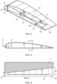
- Figure 2 shows the edge of a wing flap and a flap side edge module 8 extending from the end or edge of the flap.
- the module is shown in see-through form in figure 2 to illustrate the internal components which will be described below.
- a flap side edge module 8 has a leading edge 9 and a trailing edge 10 which align with the corresponding leading and trailing edges of the flap 7.
- the flap has an upper surface and a lower surface, wherein the upper surface and lower surface extend between the leading edge and the trailing edge. When attached to the flap of the aircraft, the upper surface faces substantially upwards and the lower surface faces substantially downwards.
- the module has a leading edge portion 11 which is substantially solid in form i.e. it is formed of a solid material. Similarly the module has a trailing edge portion 12 which also has a substantially solid construction.
- Example materials which may be used are aluminium, titanium or alloys thereof which may be conveniently processed as described further below.
- Figure 2 also illustrates a plurality of couplings which are used to selectively couple and decouple the module from the flap.
- Figure 2 shows 3 couplings, a first coupling 13 extending through the leading edge portion 11 and a pair of second and third couplings 14, 15 extending through the module body 16.
- any suitable coupling may be used but the couplings shown in figure 2 are in the form of elongate bolts which extend through holes or shafts formed in the body 16.
- the shafts each terminate at the side of the module 17 which aligns with the end of the wing flap.
- the shafts and couplings are described in further detail below.
- the module may or may not be a structural part of the flap i.e. it merely functions as a noise attenuation device at the end of the flap.
- the module may be integrated into the flap to also function as a structural part and to generate lift for example or direction air in the same way the remainder of the flap directs air.
- Figure 3 shows an end view of the wing flap module showing the aerodynamic profile and couplings at the leading edge and within the body. Sections E-E' and D-D' are described below.
- Figure 4 is a plan view of the module and wing flap.
- Figure 4 illustrates the tapered profile of the module from the leading edge 9 to trailing edge 10. As shown by the arrows the width (along the flap span-wise direction) is smaller at the leading edge than the trailing edge. The purpose for this is to compensate for the change in pressure differential from leading edge to trailing edge. The footprint of the pressure difference at the leading edge is smaller than the footprint of the pressure differential at the trailing edge
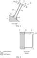
- FIG 5 is a cross-section through section E-E' in figure 3 .
- the flap 7 comprises a stud 18 which is arranged to receive a bolt 19 which extends through the body 16 of the module 8.
- a bush 20 is provided for connection to the bolt which allows for ease of replacement/repair.
- the bolt is elongate and has a distal end 21 which engages with the outer surface 22 of the module 8.
- the bolt 19 is located inside a shaft 18 which is formed of a substantially solid outer wall (in one example a titanium shaft).
- the shaft receives the elongate bolt which allows the module 8 to be coupled and de-coupled to the flap 7.
- Figure 6 shows a cross-section through section D-D' from figure 3 .
- the outer periphery 24 of the module 8 is shown in abutment with the flap 7.
- the periphery is formed of a lattice structure (described further below) which has a different density to a solid formed of the same material and specifically a lower density.
- a transition region 25, again described further below, is a region in which the material density changes from a first density to a second density by changing the density of the lattice structure.
- the outer periphery 24 defines a hollow space 16 within the module.
- a feature of the present invention is a lattice structure which allows the porosity and density of the body of the module to be controlled and adapted.
- Intricate internal lattice structures can be formed in a metallic form using additive manufacturing techniques i.e. techniques where shapes are progressively built up layer by layer.
- metal powders such as aluminium and titanium can be used to build complex geometrical shapes and structures. More specifically complex internal lattice like structures may be formed.
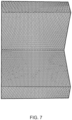
- Figure 7 shows such a lattice or matrix structure in which a network of intersecting strips or beams of metal can be seen in a generally repeating pattern. Any suitable pattern may be used depending on the desired porosity (that is the spaces between the structural members of the lattice) and the desired strength and rigidity. As can be seen in Figure 7 the structure defines open spaces which provides the porosity (and which reduces density) and which allows air to flow freely into and out of the structure.
- the pattern may be any suitable pattern. Once the geometry is determined this can be programmed into the additive manufacturing equipment and the body can be formed.
- this porous structure advantageously suppresses the vortex generation from an outer surface of a module being formed with this porosity.
- a further aspect of an invention described herein is the transition zone or region which extends between regions of different lattice density. This is illustrated in figure 8 where a first zone on the left has a higher lattice density than the zone on the right. Adapting the lattice density in this way allows the body strength and or stiffness to be optimised for the particular part of the module as well as allowing the porosity to be increased at areas where high strength and or stiffness is not needed. This allows for acoustic optimisation. It will be recognised from figure 8 that the left hand zone allows the body to be coupled structurally to the leading edge or trailing edge with greater strength.
- Figure 9 corresponds generally to figure 2 and illustrates how the lattice density can be selectively modified across the module 8.
- the leading and trailing edges 9 and 10 sit either end of the body 8 of the module.
- the dotted portions of the body illustrate the increasing density of the lattice.
- the body comprise a central portion 26 and two transitional portions 27 which are sandwiched between the ends of the body and the trailing/leading edges 9, 10.
- the trailing and leading portions are substantially solid section 28.
- the transition regions 27 exhibit a form generally similar to figure 8 and have an increasing lattice density as illustrated by the dotted regions in figure 9 .
- lattice density gradient i.e. the rate of increase in density from region 26 to region 28 will depend on the predetermined lattice geometry, strength and or stiffness required.
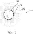
- the shaft 23 is formed of a solid titanium portion. This is surrounded by a transition zone 27 where the lattice density decreases until it corresponds to the density of the body around the coupling.
- the inside of the body may be hollow as discussed above or alternatively could be filled with a low density lattice. As shown in figure 11 multiple transition zones may be provided around the coupling portions and between the body and leading/trailing edges.
- the lattice density is increased at appropriate portions of the body where additional strength and or stiffness is required, where a connection is required or where a coupling shaft has to be defined.
- the lattice density/porosity can be controlled according to the acoustic effects at the remained of the body.
- a variety of additive manufacturing techniques could be used to form a structure described herein.
- powder bed fusion, electron beam melting or laser melting powder bed additive manufacturing machines could be used.
- An example material could be titanium Ti64 having an example density of between 10 and 50 pores per inch and a density between 3% and 40%.
- the module could be deposited directly onto the distance end of a flap, for example using additive manufacturing technique.
- a fully integrated since piece flap and noise attenuation module may be provided.
- the flap side edge module may not extend along the full length of the flap.
- the flap side edge module may be incorporated on both the first flap side edge and the second flap side edge, defined above.
- the pressure difference may vary and therefore an optimal lattice density per specific pressure difference can be implemented for optimal acoustic performance.
- the noise attenuation panel of the present invention may be configured for use in other situations.
- the noise attenuation panel may be used in landing gear components.
- the noise attenuation panel may be used in non-aerospace applications, for example wind turbines
- the structure may be applied to various parts of an aircraft, including but not limited to:
- the noise attenuation panel of the present invention comprises a porous mesh or lattice region and a transition region substantially as hereinbefore described.
- the transition region has a mesh or lattice density gradient such that the mesh or lattice density varies from a coarse mesh or lattice at one end to a fine mesh or lattice at the other.
Landscapes
- Engineering & Computer Science (AREA)
- Aviation & Aerospace Engineering (AREA)
- Mechanical Engineering (AREA)
- Soundproofing, Sound Blocking, And Sound Damping (AREA)
- Powder Metallurgy (AREA)
Claims (20)
- Klappenseitenkantenmodul zur Geräuschdämpfung, das im Gebrauch zur Befestigung an einer Flügelklappe konfiguriert ist, wobei das Modul eine Vorderkante (9), eine Hinterkante (10) und einen dazwischen befindlichen Körperabschnitt (8) umfasst, wobei die Vorderkante und die Hinterkante im Wesentlichen massiv sind, wobei sich der Körperabschnitt zwischen einer oberen und einer unteren Fläche des Klappenseitenkantenmoduls erstreckt und aus einem zentralen Abschnitt und zwei Übergangsregionen besteht, wobei der Körperabschnitt aus einer Gitterstruktur gebildet ist, wobei der zentrale Abschnitt ein poröses Netz umfasst, das eine Vielzahl von Luftdurchgängen durch das Netz definiert, wobei das poröse Netz durchgehend eine erste Gitterdichte aufweist, wobei der Körperabschnitt jeweils mit der Vorderkante und der Hinterkante mittels der Übergangsregionen (27) verbunden ist, wobei jede Übergangsregion einen Gitterstruktur-Dichtegradienten derart aufweist, dass eine Gitterdichte zwischen einer zweiten Gitterdichte angrenzend an Regionen (28) in der Nähe einer Vorderkante oder Hinterkante und der ersten Gitterdichte in einem Abschnitt der Übergangsregion angrenzend an den zentralen Abschnitt (26) variiert, wobei die erste Gitterdichte niedriger als die zweite Gitterdichte ist.
- Klappenseitenkantenmodul nach Anspruch 1, wobei die Vorderkante (9) und die Hinterkante (10) in Form eines Vollmaterials vorliegen.
- Klappenseitenkantenmodul nach Anspruch 1 oder 2, wobei sich die Gitterstruktur durch den gesamten Körperabschnitt erstreckt.
- Klappenseitenkantenmodul nach einem der Ansprüche 1 bis 2, wobei sich die Gitterstruktur um einen gesamten oder einen Teil eines Umfangs des Körperabschnitts erstreckt, um einen Hohlraum innerhalb des Körperabschnitts zu definieren.
- Klappenseitenkantenmodul nach einem der Ansprüche 1 bis 4, wobei ein Befestigungsabschnitt des Klappenseitenkantenmoduls, der im Gebrauch mit einem distalen Ende einer Klappe ausgerichtet ist, eine Übergangsregion mit einer größeren Gitterdichte als ein von dem Befestigungsabschnitt entfernter Abschnitt des Moduls umfasst.
- Klappenseitenkantenmodul nach Anspruch 5, wobei die Übergangsregion einen Gitterdichtegradienten derart aufweist, dass eine Gitterdichte zwischen einer ersten Gitterdichte in der Nähe des Körperabschnitts und einer größeren Gitterdichte an einem Befestigungsabschnitt variiert.
- Klappenseitenkantenmodul oder -element nach einem der vorhergehenden Ansprüche, wobei die Gitterstruktur in Form einer uneinheitlichen Formation vorliegt.
- Klappenseitenkantenmodul nach Anspruch 7, wobei die Gitterstruktur ein Dreiecksnetz umfasst und wobei jede Kante jedes Dreiecks eine Länge zwischen 0,7 mm und 1 mm und eine Breite zwischen 0,08 mm und 0,12 mm aufweist.
- Klappenseitenkantenmodul nach Anspruch 8, wobei die Gitterstruktur ein Dreiecksnetz umfasst und wobei jede Kante jedes Dreiecks eine Länge von etwa 0,9 mm und eine Breite von etwa 0,1 mm aufweist.
- Klappenseitenkantenmodul oder -element nach einem der vorhergehenden Ansprüche, wobei die Gitterstruktur in Form einer Metall- oder Polymerschaumstruktur vorliegt.
- Klappenseitenkantenmodul oder -element nach einem der vorhergehenden Ansprüche, wobei die Gitterstruktur in Form von Titan oder einer Titanlegierung vorliegt.
- Klappenseitenkantenmodul nach einem der Ansprüche 1 bis 11, wobei das Klappenseitenkantenmodul mindestens eine Kopplung (13, 14, 15) umfasst, die so konfiguriert ist, dass sie im Gebrauch das Modul an einer Kante einer Klappe befestigt.
- Klappenseitenkantenmodul nach Anspruch 12, wobei eine der mindestens einen Kopplung in der Vorderkante und/oder der Hinterkante ausgebildet ist.
- Klappenseitenkantenmodul nach Anspruch 12 oder 13, wobei eine der mindestens einen Kopplung in dem Körperabschnitt ausgebildet ist.
- Klappenseitenkantenmodul nach Anspruch 14, wobei die Kopplung einen Schaft umfasst, der sich durch den Körperabschnitt erstreckt und so angeordnet ist, dass er im Gebrauch ein Befestigungselement aufnimmt, das sich durch den Körperabschnitt erstreckt.
- Klappenseitenkantenmodul nach Anspruch 15, wobei der Schaft eine erste Schicht und eine zweite umgebende Schicht umfasst, wobei sich die erste Schicht und die zweite Schicht jeweils um den Umfang des Schafts erstrecken und wobei die erste Schicht eine höhere Gitterdichte als die zweite umgebende Schicht aufweist.
- Klappenseitenkantenmodul nach Anspruch 16, wobei der Schaft ferner eine Übergangsschicht zwischen der ersten Schicht und der zweiten umgebenden Schicht umfasst, in der die Gitterdichte über die Übergangsschicht hinweg in Richtung der umgebenden zweiten Schicht abnimmt.
- Geräuschdämpfungsplatte, umfassend;einen ersten Abschnitt, der sich zwischen einer oberen und einer unteren Fläche der Geräuschdämpfungsplatte erstreckt und ein poröses Netz umfasst, das eine Vielzahl von Luftdurchgängen durch das Netz definiert, wobei das poröse Netz durchgehend eine erste Gitterdichte umfasst; einen zweiten, im Wesentlichen massiven Abschnitt; undeine Übergangsregion, die aus einem zwischen dem ersten und dem zweiten Abschnitt befindlichen Netz gebildet ist, wobei die Dichte des Netzes in der Übergangsregion von einer zweiten Gitterdichte angrenzend an den massiven Abschnitt auf die erste Gitterdichte angrenzend an den porösen Netzabschnitt abnimmt.
- Verfahren zum Herstellen eines Klappenseitenkantenmoduls, wobei das Modul im Gebrauch zur Verbindung mit einer Flügelklappe eingerichtet ist, wobei das Klappenseitenkantenmodul eine Vorderkante (9), eine Hinterkante (10) und einen Körper (8) umfasst, der eine Gitterstruktur aufweist, wobei die Vorderkante und die Hinterkante im Wesentlichen massiv sind, wobei die Gitterstruktur über zumindest einen Abschnitt des Körpers eine uneinheitliche Gitterdichte aufweist;
wobei das Verfahren die folgenden Schritte umfasst:
Bilden eines Körperabschnitts, der sich zwischen einer oberen und einer unteren Fläche des Klappenseitenkantenmoduls erstreckt und aus einem zentralen Abschnitt und zwei Übergangsregionen besteht, wobei der Körperabschnitt aus einer Gitterstruktur gebildet wird, wobei der zentrale Abschnitt durchgehend eine erste Gitterdichte aufweist und wobei die Übergangsregionen (27) zwischen dem zentralen Abschnitt und Regionen (28) in der Nähe der Vorder- oder Hinterkante bereitgestellt werden und wobei jede Übergangsregion einen Gitterstruktur-Dichtegradienten derart aufweist, dass eine Gitterdichte zwischen einer zweiten Gitterdichte angrenzend an Regionen (28) in der Nähe einer Vorderkante oder Hinterkante und der ersten Gitterdichte variiert, wobei die erste Gitterdichte niedriger als die zweite Gitterdichte ist. - Verfahren nach Anspruch 19, wobei die Gitterstruktur mittels eines Prozesses additiv hergestellt wird, der ausgewählt ist aus Pulverbettschmelzverfahren, direktem Metalllasersintern (DMLS), Elektronenstrahlschmelzen (EBM), selektivem Laserschmelzen (SLM), selektivem Lasersintern (SLS), direkter Metalldrahtabscheidung, direkter Metallpulverabscheidung oder Fused Deposition Modeling (FDM).
Applications Claiming Priority (2)
| Application Number | Priority Date | Filing Date | Title |
|---|---|---|---|
| GB1716651.3A GB2567445B (en) | 2017-10-11 | 2017-10-11 | Noise attenuation panel |
| PCT/EP2018/077763 WO2019072980A1 (en) | 2017-10-11 | 2018-10-11 | NOISE MITIGATION PANEL |
Publications (3)
| Publication Number | Publication Date |
|---|---|
| EP3694776A1 EP3694776A1 (de) | 2020-08-19 |
| EP3694776B1 true EP3694776B1 (de) | 2024-08-07 |
| EP3694776B8 EP3694776B8 (de) | 2025-01-01 |
Family
ID=60326918
Family Applications (1)
| Application Number | Title | Priority Date | Filing Date |
|---|---|---|---|
| EP18789575.0A Active EP3694776B8 (de) | 2017-10-11 | 2018-10-11 | Lärmdämpfungsplatte |
Country Status (6)
| Country | Link |
|---|---|
| US (1) | US11591065B2 (de) |
| EP (1) | EP3694776B8 (de) |
| CN (1) | CN111836759B (de) |
| CA (1) | CA3078663A1 (de) |
| GB (1) | GB2567445B (de) |
| WO (1) | WO2019072980A1 (de) |
Families Citing this family (6)
| Publication number | Priority date | Publication date | Assignee | Title |
|---|---|---|---|---|
| DE102017130884B4 (de) * | 2017-12-21 | 2019-08-14 | Airbus Defence and Space GmbH | Luftfahrzeug und Verfahren zum Herstellen eines Luftfahrzeugs |
| NL2026520B1 (en) * | 2020-09-23 | 2022-05-24 | Univ Delft Tech | An aircraft wing provided with a trailing edge region |
| CN112678150B (zh) * | 2020-12-31 | 2024-04-26 | 中国商用飞机有限责任公司 | 飞机后缘襟翼 |
| EP4063260B1 (de) | 2021-03-23 | 2025-01-29 | Airbus Operations GmbH | Bewegliche aerodynamische fläche für ein flugzeug |
| FR3124487A1 (fr) * | 2021-06-29 | 2022-12-30 | Airbus Operations | Élément de liaison entre un premier et un deuxième élément structurel de fuselage d’un aéronef permettant une dissipation améliorée des efforts. |
| CN118977845A (zh) * | 2024-09-14 | 2024-11-19 | 上海机电工程研究所 | 空气舵前缘热应力释放结构及飞行器 |
Family Cites Families (10)
| Publication number | Priority date | Publication date | Assignee | Title |
|---|---|---|---|---|
| US5923003A (en) * | 1996-09-09 | 1999-07-13 | Northrop Grumman Corporation | Extended reaction acoustic liner for jet engines and the like |
| US8376261B2 (en) * | 2002-11-01 | 2013-02-19 | Airbus Uk Limited | Landing gear |
| US9566758B2 (en) | 2010-10-19 | 2017-02-14 | Massachusetts Institute Of Technology | Digital flexural materials |
| US9227719B2 (en) * | 2011-03-11 | 2016-01-05 | The United States Of America As Represented By The Administrator Of The National Aeronautics And Space Administration | Reactive orthotropic lattice diffuser for noise reduction |
| US9199721B2 (en) * | 2013-01-29 | 2015-12-01 | Gulfstream Aerospace Corporation | Wing flaps for aircraft and methods for making the same |
| US9222229B1 (en) * | 2013-10-10 | 2015-12-29 | Hrl Laboratories, Llc | Tunable sandwich-structured acoustic barriers |
| US9982544B2 (en) * | 2014-11-12 | 2018-05-29 | United Technologies Corporation | Cooling having tailored flow resistance |
| CA2970780C (en) * | 2014-12-18 | 2022-11-08 | Bombardier Inc. | Sound absorbers for airframe components |
| US10232549B2 (en) * | 2015-09-10 | 2019-03-19 | The Boeing Company | Geometric sound absorption via additive manufacturing |
| CN106694884B (zh) * | 2016-12-29 | 2020-02-21 | 西安铂力特增材技术股份有限公司 | 一种具有梯度功能性的镂空点阵夹层及其制造方法 |
-
2017
- 2017-10-11 GB GB1716651.3A patent/GB2567445B/en active Active
-
2018
- 2018-10-11 WO PCT/EP2018/077763 patent/WO2019072980A1/en not_active Ceased
- 2018-10-11 US US16/754,768 patent/US11591065B2/en active Active
- 2018-10-11 CA CA3078663A patent/CA3078663A1/en active Pending
- 2018-10-11 CN CN201880065849.3A patent/CN111836759B/zh active Active
- 2018-10-11 EP EP18789575.0A patent/EP3694776B8/de active Active
Also Published As
| Publication number | Publication date |
|---|---|
| GB201716651D0 (en) | 2017-11-22 |
| BR112020006365A2 (pt) | 2020-09-24 |
| CN111836759B (zh) | 2024-04-16 |
| CA3078663A1 (en) | 2019-04-18 |
| CN111836759A (zh) | 2020-10-27 |
| US20200298953A1 (en) | 2020-09-24 |
| WO2019072980A1 (en) | 2019-04-18 |
| US11591065B2 (en) | 2023-02-28 |
| EP3694776B8 (de) | 2025-01-01 |
| GB2567445B (en) | 2020-07-29 |
| GB2567445A (en) | 2019-04-17 |
| EP3694776A1 (de) | 2020-08-19 |
Similar Documents
| Publication | Publication Date | Title |
|---|---|---|
| EP3694776B1 (de) | Lärmdämpfungsplatte | |
| EP0532093B1 (de) | Perforierte Flügelabdeckung mit variabeler Durchlässigkeit | |
| EP2891606B1 (de) | Strömungskörper, Verfahren zur Herstellung eines Strömungskörpers und Flugzeug mit solch einem Strömungskörper | |
| EP2895392B1 (de) | Metallische sandwichstruktur mit kleinem biegeradius | |
| US7866609B2 (en) | Passive removal of suction air for laminar flow control, and associated systems and methods | |
| CN107031817B (zh) | 具有层流控制的前缘及其制造方法 | |
| CA2652661C (en) | A stringer for an aircraft wing and a method of forming thereof | |
| US8573530B2 (en) | Aircraft with rear annular tail | |
| US9511848B2 (en) | Profile plate portion for use as an outer wall of a flow body, method for manufacturing a profile plate portion and flow body component comprising a suction-extraction device for fluid | |
| US9835112B2 (en) | Thrust reverser cascade | |
| US9227719B2 (en) | Reactive orthotropic lattice diffuser for noise reduction | |
| EP3205575B1 (de) | Laminarströmungsplatte | |
| US8882469B2 (en) | Structural element for an aircraft or spacecraft and method for producing such a structural element | |
| US9199721B2 (en) | Wing flaps for aircraft and methods for making the same | |
| Hileman et al. | Aerodynamic and Aeroacoustic Three-Dimensional Design for a" Silent" Aircraft | |
| US6905092B2 (en) | Laminar-flow airfoil | |
| EP3551534B1 (de) | Flügelvorrichtung | |
| Sureka et al. | Modeling and structural analysis on A300 flight wing by using ANSYS | |
| DE102016123096B4 (de) | Steuerflächenbauteil für eine Auftriebshilfevorrichtung eines Luftfahrzeugs sowie Herstellungsverfahren hierfür | |
| Wakayama et al. | Evaluation of adaptive compliant trailing edge technology | |
| CN112533824A (zh) | 用于改进封闭机翼飞行器概念的方法以及对应的飞行器构造 | |
| EP2610170A1 (de) | Luftwiderstandsverringerung für ein Fahrwerk mit Landekufen eines Drehflügler | |
| BR112020006365B1 (pt) | Módulo de bordo lateral de flape para atenuação de ruído, painel de atenuação de ruído, e, método para fabricar um módulo de bordo lateral de flape | |
| US10625872B2 (en) | Composite fan cowl having core with varying thickness | |
| Traub | A Suction Panel Concept for Additive Manufacturing |
Legal Events
| Date | Code | Title | Description |
|---|---|---|---|
| STAA | Information on the status of an ep patent application or granted ep patent |
Free format text: STATUS: UNKNOWN |
|
| STAA | Information on the status of an ep patent application or granted ep patent |
Free format text: STATUS: THE INTERNATIONAL PUBLICATION HAS BEEN MADE |
|
| PUAI | Public reference made under article 153(3) epc to a published international application that has entered the european phase |
Free format text: ORIGINAL CODE: 0009012 |
|
| STAA | Information on the status of an ep patent application or granted ep patent |
Free format text: STATUS: REQUEST FOR EXAMINATION WAS MADE |
|
| 17P | Request for examination filed |
Effective date: 20200511 |
|
| AK | Designated contracting states |
Kind code of ref document: A1 Designated state(s): AL AT BE BG CH CY CZ DE DK EE ES FI FR GB GR HR HU IE IS IT LI LT LU LV MC MK MT NL NO PL PT RO RS SE SI SK SM TR |
|
| AX | Request for extension of the european patent |
Extension state: BA ME |
|
| DAV | Request for validation of the european patent (deleted) | ||
| DAX | Request for extension of the european patent (deleted) | ||
| STAA | Information on the status of an ep patent application or granted ep patent |
Free format text: STATUS: EXAMINATION IS IN PROGRESS |
|
| 17Q | First examination report despatched |
Effective date: 20210526 |
|
| GRAP | Despatch of communication of intention to grant a patent |
Free format text: ORIGINAL CODE: EPIDOSNIGR1 |
|
| STAA | Information on the status of an ep patent application or granted ep patent |
Free format text: STATUS: GRANT OF PATENT IS INTENDED |
|
| RIC1 | Information provided on ipc code assigned before grant |
Ipc: B64C 25/00 20060101ALI20240131BHEP Ipc: B64C 9/18 20060101ALI20240131BHEP Ipc: B64C 3/26 20060101ALI20240131BHEP Ipc: B64C 3/22 20060101ALI20240131BHEP Ipc: B64C 1/08 20060101ALI20240131BHEP Ipc: B64D 33/02 20060101ALI20240131BHEP Ipc: B64C 1/40 20060101AFI20240131BHEP |
|
| INTG | Intention to grant announced |
Effective date: 20240228 |
|
| GRAS | Grant fee paid |
Free format text: ORIGINAL CODE: EPIDOSNIGR3 |
|
| GRAA | (expected) grant |
Free format text: ORIGINAL CODE: 0009210 |
|
| STAA | Information on the status of an ep patent application or granted ep patent |
Free format text: STATUS: THE PATENT HAS BEEN GRANTED |
|
| AK | Designated contracting states |
Kind code of ref document: B1 Designated state(s): AL AT BE BG CH CY CZ DE DK EE ES FI FR GB GR HR HU IE IS IT LI LT LU LV MC MK MT NL NO PL PT RO RS SE SI SK SM TR |
|
| REG | Reference to a national code |
Ref country code: GB Ref legal event code: FG4D |
|
| REG | Reference to a national code |
Ref country code: CH Ref legal event code: EP |
|
| REG | Reference to a national code |
Ref country code: DE Ref legal event code: R096 Ref document number: 602018072814 Country of ref document: DE |
|
| REG | Reference to a national code |
Ref country code: IE Ref legal event code: FG4D |
|
| REG | Reference to a national code |
Ref country code: LT Ref legal event code: MG9D |
|
| REG | Reference to a national code |
Ref country code: DE Ref legal event code: R081 Ref document number: 602018072814 Country of ref document: DE Owner name: GKN FOKKER AEROSPACE B.V., NL Free format text: FORMER OWNER: FOKKER AEROSTRUCTURES B.V., PAPENDRECHT, NL |
|
| P01 | Opt-out of the competence of the unified patent court (upc) registered |
Free format text: CASE NUMBER: APP_59414/2024 Effective date: 20241031 |
|
| REG | Reference to a national code |
Ref country code: NL Ref legal event code: MP Effective date: 20240807 |
|
| REG | Reference to a national code |
Ref country code: CH Ref legal event code: PK Free format text: BERICHTIGUNG B8 |
|
| RAP4 | Party data changed (patent owner data changed or rights of a patent transferred) |
Owner name: GKN FOKKER AEROSPACE B.V. |
|
| PG25 | Lapsed in a contracting state [announced via postgrant information from national office to epo] |
Ref country code: NO Free format text: LAPSE BECAUSE OF FAILURE TO SUBMIT A TRANSLATION OF THE DESCRIPTION OR TO PAY THE FEE WITHIN THE PRESCRIBED TIME-LIMIT Effective date: 20241107 |
|
| REG | Reference to a national code |
Ref country code: AT Ref legal event code: MK05 Ref document number: 1710645 Country of ref document: AT Kind code of ref document: T Effective date: 20240807 |
|
| PG25 | Lapsed in a contracting state [announced via postgrant information from national office to epo] |
Ref country code: NL Free format text: LAPSE BECAUSE OF FAILURE TO SUBMIT A TRANSLATION OF THE DESCRIPTION OR TO PAY THE FEE WITHIN THE PRESCRIBED TIME-LIMIT Effective date: 20240807 Ref country code: FI Free format text: LAPSE BECAUSE OF FAILURE TO SUBMIT A TRANSLATION OF THE DESCRIPTION OR TO PAY THE FEE WITHIN THE PRESCRIBED TIME-LIMIT Effective date: 20240807 Ref country code: PL Free format text: LAPSE BECAUSE OF FAILURE TO SUBMIT A TRANSLATION OF THE DESCRIPTION OR TO PAY THE FEE WITHIN THE PRESCRIBED TIME-LIMIT Effective date: 20240807 Ref country code: GR Free format text: LAPSE BECAUSE OF FAILURE TO SUBMIT A TRANSLATION OF THE DESCRIPTION OR TO PAY THE FEE WITHIN THE PRESCRIBED TIME-LIMIT Effective date: 20241108 Ref country code: PT Free format text: LAPSE BECAUSE OF FAILURE TO SUBMIT A TRANSLATION OF THE DESCRIPTION OR TO PAY THE FEE WITHIN THE PRESCRIBED TIME-LIMIT Effective date: 20241209 |
|
| PG25 | Lapsed in a contracting state [announced via postgrant information from national office to epo] |
Ref country code: BG Free format text: LAPSE BECAUSE OF FAILURE TO SUBMIT A TRANSLATION OF THE DESCRIPTION OR TO PAY THE FEE WITHIN THE PRESCRIBED TIME-LIMIT Effective date: 20240807 |
|
| PG25 | Lapsed in a contracting state [announced via postgrant information from national office to epo] |
Ref country code: LV Free format text: LAPSE BECAUSE OF FAILURE TO SUBMIT A TRANSLATION OF THE DESCRIPTION OR TO PAY THE FEE WITHIN THE PRESCRIBED TIME-LIMIT Effective date: 20240807 |
|
| PG25 | Lapsed in a contracting state [announced via postgrant information from national office to epo] |
Ref country code: IS Free format text: LAPSE BECAUSE OF FAILURE TO SUBMIT A TRANSLATION OF THE DESCRIPTION OR TO PAY THE FEE WITHIN THE PRESCRIBED TIME-LIMIT Effective date: 20241207 Ref country code: AT Free format text: LAPSE BECAUSE OF FAILURE TO SUBMIT A TRANSLATION OF THE DESCRIPTION OR TO PAY THE FEE WITHIN THE PRESCRIBED TIME-LIMIT Effective date: 20240807 |
|
| PG25 | Lapsed in a contracting state [announced via postgrant information from national office to epo] |
Ref country code: HR Free format text: LAPSE BECAUSE OF FAILURE TO SUBMIT A TRANSLATION OF THE DESCRIPTION OR TO PAY THE FEE WITHIN THE PRESCRIBED TIME-LIMIT Effective date: 20240807 |
|
| PG25 | Lapsed in a contracting state [announced via postgrant information from national office to epo] |
Ref country code: ES Free format text: LAPSE BECAUSE OF FAILURE TO SUBMIT A TRANSLATION OF THE DESCRIPTION OR TO PAY THE FEE WITHIN THE PRESCRIBED TIME-LIMIT Effective date: 20240807 Ref country code: RS Free format text: LAPSE BECAUSE OF FAILURE TO SUBMIT A TRANSLATION OF THE DESCRIPTION OR TO PAY THE FEE WITHIN THE PRESCRIBED TIME-LIMIT Effective date: 20241107 |
|
| PG25 | Lapsed in a contracting state [announced via postgrant information from national office to epo] |
Ref country code: RS Free format text: LAPSE BECAUSE OF FAILURE TO SUBMIT A TRANSLATION OF THE DESCRIPTION OR TO PAY THE FEE WITHIN THE PRESCRIBED TIME-LIMIT Effective date: 20241107 Ref country code: PT Free format text: LAPSE BECAUSE OF FAILURE TO SUBMIT A TRANSLATION OF THE DESCRIPTION OR TO PAY THE FEE WITHIN THE PRESCRIBED TIME-LIMIT Effective date: 20241209 Ref country code: PL Free format text: LAPSE BECAUSE OF FAILURE TO SUBMIT A TRANSLATION OF THE DESCRIPTION OR TO PAY THE FEE WITHIN THE PRESCRIBED TIME-LIMIT Effective date: 20240807 Ref country code: NO Free format text: LAPSE BECAUSE OF FAILURE TO SUBMIT A TRANSLATION OF THE DESCRIPTION OR TO PAY THE FEE WITHIN THE PRESCRIBED TIME-LIMIT Effective date: 20241107 Ref country code: NL Free format text: LAPSE BECAUSE OF FAILURE TO SUBMIT A TRANSLATION OF THE DESCRIPTION OR TO PAY THE FEE WITHIN THE PRESCRIBED TIME-LIMIT Effective date: 20240807 Ref country code: LV Free format text: LAPSE BECAUSE OF FAILURE TO SUBMIT A TRANSLATION OF THE DESCRIPTION OR TO PAY THE FEE WITHIN THE PRESCRIBED TIME-LIMIT Effective date: 20240807 Ref country code: IS Free format text: LAPSE BECAUSE OF FAILURE TO SUBMIT A TRANSLATION OF THE DESCRIPTION OR TO PAY THE FEE WITHIN THE PRESCRIBED TIME-LIMIT Effective date: 20241207 Ref country code: HR Free format text: LAPSE BECAUSE OF FAILURE TO SUBMIT A TRANSLATION OF THE DESCRIPTION OR TO PAY THE FEE WITHIN THE PRESCRIBED TIME-LIMIT Effective date: 20240807 Ref country code: GR Free format text: LAPSE BECAUSE OF FAILURE TO SUBMIT A TRANSLATION OF THE DESCRIPTION OR TO PAY THE FEE WITHIN THE PRESCRIBED TIME-LIMIT Effective date: 20241108 Ref country code: FI Free format text: LAPSE BECAUSE OF FAILURE TO SUBMIT A TRANSLATION OF THE DESCRIPTION OR TO PAY THE FEE WITHIN THE PRESCRIBED TIME-LIMIT Effective date: 20240807 Ref country code: ES Free format text: LAPSE BECAUSE OF FAILURE TO SUBMIT A TRANSLATION OF THE DESCRIPTION OR TO PAY THE FEE WITHIN THE PRESCRIBED TIME-LIMIT Effective date: 20240807 Ref country code: BG Free format text: LAPSE BECAUSE OF FAILURE TO SUBMIT A TRANSLATION OF THE DESCRIPTION OR TO PAY THE FEE WITHIN THE PRESCRIBED TIME-LIMIT Effective date: 20240807 Ref country code: AT Free format text: LAPSE BECAUSE OF FAILURE TO SUBMIT A TRANSLATION OF THE DESCRIPTION OR TO PAY THE FEE WITHIN THE PRESCRIBED TIME-LIMIT Effective date: 20240807 |
|
| PG25 | Lapsed in a contracting state [announced via postgrant information from national office to epo] |
Ref country code: DK Free format text: LAPSE BECAUSE OF FAILURE TO SUBMIT A TRANSLATION OF THE DESCRIPTION OR TO PAY THE FEE WITHIN THE PRESCRIBED TIME-LIMIT Effective date: 20240807 Ref country code: SM Free format text: LAPSE BECAUSE OF FAILURE TO SUBMIT A TRANSLATION OF THE DESCRIPTION OR TO PAY THE FEE WITHIN THE PRESCRIBED TIME-LIMIT Effective date: 20240807 Ref country code: RO Free format text: LAPSE BECAUSE OF FAILURE TO SUBMIT A TRANSLATION OF THE DESCRIPTION OR TO PAY THE FEE WITHIN THE PRESCRIBED TIME-LIMIT Effective date: 20240807 |
|
| PG25 | Lapsed in a contracting state [announced via postgrant information from national office to epo] |
Ref country code: CZ Free format text: LAPSE BECAUSE OF FAILURE TO SUBMIT A TRANSLATION OF THE DESCRIPTION OR TO PAY THE FEE WITHIN THE PRESCRIBED TIME-LIMIT Effective date: 20240807 |
|
| PG25 | Lapsed in a contracting state [announced via postgrant information from national office to epo] |
Ref country code: SK Free format text: LAPSE BECAUSE OF FAILURE TO SUBMIT A TRANSLATION OF THE DESCRIPTION OR TO PAY THE FEE WITHIN THE PRESCRIBED TIME-LIMIT Effective date: 20240807 |
|
| REG | Reference to a national code |
Ref country code: DE Ref legal event code: R097 Ref document number: 602018072814 Country of ref document: DE |
|
| REG | Reference to a national code |
Ref country code: CH Ref legal event code: PL |
|
| PLBE | No opposition filed within time limit |
Free format text: ORIGINAL CODE: 0009261 |
|
| STAA | Information on the status of an ep patent application or granted ep patent |
Free format text: STATUS: NO OPPOSITION FILED WITHIN TIME LIMIT |
|
| PG25 | Lapsed in a contracting state [announced via postgrant information from national office to epo] |
Ref country code: MC Free format text: LAPSE BECAUSE OF FAILURE TO SUBMIT A TRANSLATION OF THE DESCRIPTION OR TO PAY THE FEE WITHIN THE PRESCRIBED TIME-LIMIT Effective date: 20240807 |
|
| PG25 | Lapsed in a contracting state [announced via postgrant information from national office to epo] |
Ref country code: BE Free format text: LAPSE BECAUSE OF NON-PAYMENT OF DUE FEES Effective date: 20241031 Ref country code: LU Free format text: LAPSE BECAUSE OF NON-PAYMENT OF DUE FEES Effective date: 20241011 |
|
| 26N | No opposition filed |
Effective date: 20250508 |
|
| PG25 | Lapsed in a contracting state [announced via postgrant information from national office to epo] |
Ref country code: CH Free format text: LAPSE BECAUSE OF NON-PAYMENT OF DUE FEES Effective date: 20241031 |
|
| REG | Reference to a national code |
Ref country code: BE Ref legal event code: MM Effective date: 20241031 |
|
| PG25 | Lapsed in a contracting state [announced via postgrant information from national office to epo] |
Ref country code: SE Free format text: LAPSE BECAUSE OF FAILURE TO SUBMIT A TRANSLATION OF THE DESCRIPTION OR TO PAY THE FEE WITHIN THE PRESCRIBED TIME-LIMIT Effective date: 20240807 |
|
| PG25 | Lapsed in a contracting state [announced via postgrant information from national office to epo] |
Ref country code: IE Free format text: LAPSE BECAUSE OF NON-PAYMENT OF DUE FEES Effective date: 20241011 |
|
| PGFP | Annual fee paid to national office [announced via postgrant information from national office to epo] |
Ref country code: DE Payment date: 20251210 Year of fee payment: 8 |
|
| PGFP | Annual fee paid to national office [announced via postgrant information from national office to epo] |
Ref country code: GB Payment date: 20251204 Year of fee payment: 8 |
|
| PGFP | Annual fee paid to national office [announced via postgrant information from national office to epo] |
Ref country code: FR Payment date: 20251218 Year of fee payment: 8 |
|
| PG25 | Lapsed in a contracting state [announced via postgrant information from national office to epo] |
Ref country code: IT Free format text: LAPSE BECAUSE OF FAILURE TO SUBMIT A TRANSLATION OF THE DESCRIPTION OR TO PAY THE FEE WITHIN THE PRESCRIBED TIME-LIMIT Effective date: 20240807 Ref country code: CY Free format text: LAPSE BECAUSE OF FAILURE TO SUBMIT A TRANSLATION OF THE DESCRIPTION OR TO PAY THE FEE WITHIN THE PRESCRIBED TIME-LIMIT; INVALID AB INITIO Effective date: 20181011 |
|
| PG25 | Lapsed in a contracting state [announced via postgrant information from national office to epo] |
Ref country code: HU Free format text: LAPSE BECAUSE OF FAILURE TO SUBMIT A TRANSLATION OF THE DESCRIPTION OR TO PAY THE FEE WITHIN THE PRESCRIBED TIME-LIMIT; INVALID AB INITIO Effective date: 20181011 |