EP3694639B1 - Dispositif de melange et de distribution avec ouverture longitudinale - Google Patents
Dispositif de melange et de distribution avec ouverture longitudinale Download PDFInfo
- Publication number
- EP3694639B1 EP3694639B1 EP18778922.7A EP18778922A EP3694639B1 EP 3694639 B1 EP3694639 B1 EP 3694639B1 EP 18778922 A EP18778922 A EP 18778922A EP 3694639 B1 EP3694639 B1 EP 3694639B1
- Authority
- EP
- European Patent Office
- Prior art keywords
- zone
- mixing
- distribution
- fluids
- chamber
- Prior art date
- Legal status (The legal status is an assumption and is not a legal conclusion. Google has not performed a legal analysis and makes no representation as to the accuracy of the status listed.)
- Active
Links
Images



Classifications
-
- B—PERFORMING OPERATIONS; TRANSPORTING
- B01—PHYSICAL OR CHEMICAL PROCESSES OR APPARATUS IN GENERAL
- B01J—CHEMICAL OR PHYSICAL PROCESSES, e.g. CATALYSIS OR COLLOID CHEMISTRY; THEIR RELEVANT APPARATUS
- B01J8/00—Chemical or physical processes in general, conducted in the presence of fluids and solid particles; Apparatus for such processes
- B01J8/02—Chemical or physical processes in general, conducted in the presence of fluids and solid particles; Apparatus for such processes with stationary particles, e.g. in fixed beds
- B01J8/04—Chemical or physical processes in general, conducted in the presence of fluids and solid particles; Apparatus for such processes with stationary particles, e.g. in fixed beds the fluid passing successively through two or more beds
- B01J8/0492—Feeding reactive fluids
-
- B—PERFORMING OPERATIONS; TRANSPORTING
- B01—PHYSICAL OR CHEMICAL PROCESSES OR APPARATUS IN GENERAL
- B01J—CHEMICAL OR PHYSICAL PROCESSES, e.g. CATALYSIS OR COLLOID CHEMISTRY; THEIR RELEVANT APPARATUS
- B01J8/00—Chemical or physical processes in general, conducted in the presence of fluids and solid particles; Apparatus for such processes
- B01J8/02—Chemical or physical processes in general, conducted in the presence of fluids and solid particles; Apparatus for such processes with stationary particles, e.g. in fixed beds
- B01J8/04—Chemical or physical processes in general, conducted in the presence of fluids and solid particles; Apparatus for such processes with stationary particles, e.g. in fixed beds the fluid passing successively through two or more beds
-
- B—PERFORMING OPERATIONS; TRANSPORTING
- B01—PHYSICAL OR CHEMICAL PROCESSES OR APPARATUS IN GENERAL
- B01J—CHEMICAL OR PHYSICAL PROCESSES, e.g. CATALYSIS OR COLLOID CHEMISTRY; THEIR RELEVANT APPARATUS
- B01J8/00—Chemical or physical processes in general, conducted in the presence of fluids and solid particles; Apparatus for such processes
- B01J8/02—Chemical or physical processes in general, conducted in the presence of fluids and solid particles; Apparatus for such processes with stationary particles, e.g. in fixed beds
- B01J8/04—Chemical or physical processes in general, conducted in the presence of fluids and solid particles; Apparatus for such processes with stationary particles, e.g. in fixed beds the fluid passing successively through two or more beds
- B01J8/0446—Chemical or physical processes in general, conducted in the presence of fluids and solid particles; Apparatus for such processes with stationary particles, e.g. in fixed beds the fluid passing successively through two or more beds the flow within the beds being predominantly vertical
- B01J8/0449—Chemical or physical processes in general, conducted in the presence of fluids and solid particles; Apparatus for such processes with stationary particles, e.g. in fixed beds the fluid passing successively through two or more beds the flow within the beds being predominantly vertical in two or more cylindrical beds
- B01J8/0453—Chemical or physical processes in general, conducted in the presence of fluids and solid particles; Apparatus for such processes with stationary particles, e.g. in fixed beds the fluid passing successively through two or more beds the flow within the beds being predominantly vertical in two or more cylindrical beds the beds being superimposed one above the other
-
- B—PERFORMING OPERATIONS; TRANSPORTING
- B01—PHYSICAL OR CHEMICAL PROCESSES OR APPARATUS IN GENERAL
- B01J—CHEMICAL OR PHYSICAL PROCESSES, e.g. CATALYSIS OR COLLOID CHEMISTRY; THEIR RELEVANT APPARATUS
- B01J2208/00—Processes carried out in the presence of solid particles; Reactors therefor
- B01J2208/00796—Details of the reactor or of the particulate material
- B01J2208/00823—Mixing elements
- B01J2208/00831—Stationary elements
- B01J2208/00849—Stationary elements outside the bed, e.g. baffles
-
- B—PERFORMING OPERATIONS; TRANSPORTING
- B01—PHYSICAL OR CHEMICAL PROCESSES OR APPARATUS IN GENERAL
- B01J—CHEMICAL OR PHYSICAL PROCESSES, e.g. CATALYSIS OR COLLOID CHEMISTRY; THEIR RELEVANT APPARATUS
- B01J2208/00—Processes carried out in the presence of solid particles; Reactors therefor
- B01J2208/00796—Details of the reactor or of the particulate material
- B01J2208/00893—Feeding means for the reactants
- B01J2208/0092—Perforated plates
-
- B—PERFORMING OPERATIONS; TRANSPORTING
- B01—PHYSICAL OR CHEMICAL PROCESSES OR APPARATUS IN GENERAL
- B01J—CHEMICAL OR PHYSICAL PROCESSES, e.g. CATALYSIS OR COLLOID CHEMISTRY; THEIR RELEVANT APPARATUS
- B01J2208/00—Processes carried out in the presence of solid particles; Reactors therefor
- B01J2208/00796—Details of the reactor or of the particulate material
- B01J2208/00893—Feeding means for the reactants
- B01J2208/00929—Provided with baffles
-
- B—PERFORMING OPERATIONS; TRANSPORTING
- B01—PHYSICAL OR CHEMICAL PROCESSES OR APPARATUS IN GENERAL
- B01J—CHEMICAL OR PHYSICAL PROCESSES, e.g. CATALYSIS OR COLLOID CHEMISTRY; THEIR RELEVANT APPARATUS
- B01J2208/00—Processes carried out in the presence of solid particles; Reactors therefor
- B01J2208/00796—Details of the reactor or of the particulate material
- B01J2208/00938—Flow distribution elements
Definitions
- the present invention applies to the field of exothermic reactions and more particularly to hydrotreatment, hydrodesulphurization, hydrodenitrogenation, hydrocracking, hydrogenation, hydrodeoxygenation, hydroisomerization, hydrodeparaffinization or else. hydrodearomatization carried out in a fixed bed reactor.
- the invention relates more particularly to a device for mixing and distributing fluids in a reactor with downward co-current flow and its use for carrying out exothermic reactions.
- the exothermic reactions carried out for example in refining and / or in petrochemicals need to be cooled by an additional fluid, called quenching fluid, to avoid thermal runaway of the catalytic reactor in which they are carried out.
- the catalytic reactors used for these reactions generally comprise at least one bed of solid catalyst.
- the exothermic nature of the reactions requires maintaining a uniform axial temperature gradient over the reactor section, and a radial temperature gradient close to zero within the reactor in order to avoid the existence of hot spots in the catalyst bed included in the reactor. the reactor. Areas that are too hot can prematurely decrease the activity of the catalyst and / or lead to non-selective reactions and / or lead to thermal runaways. It is therefore important to have at least one mixing chamber in a reactor, located between two catalyst beds, which allows a homogeneous temperature distribution of the fluids over a reactor section and cooling of the reaction fluids to a desired temperature.
- the document FR 2 824 495 A1 describes a quenching device making it possible to ensure an efficient exchange between the quenching fluid (s) and the process fluid (s).
- This device is integrated into an enclosure and comprises a rod for injecting the quenching fluid, a baffle for collecting the fluids, the quenching box proper, operating the mixture between the quenching fluid and the reaction fluid flowing in such a way. descending, and a distribution system composed of a perforated bowl and a distribution plate.
- the quenching box includes a deflector ensuring the swirling movement of the fluids in a direction that is substantially non-radial and not parallel to the axis of said enclosure and downstream of the deflector, in the direction of circulation of the reaction fluid, at least one section of outlet passage for the mixture of fluids formed in the box.
- This device comprises a horizontal collection means provided with a vertical collection pipe to receive the fluids, an injection means placed in the collection pipe, and an annular mixing chamber of circular section located downstream of the collection means in the direction of flow of fluids.
- the mixing chamber comprises an inlet end connected to the collection pipe and an outlet end allowing the passage of fluids, as well as a horizontal pre-distribution plate comprising at least one chimney.
- the mixing zone comprises a fluid mixing chamber and a fluid exchange chamber connected and in communication with the mixing chamber.
- the mixing enclosure is preferably located above the exchange enclosure.
- An object of the present invention aims to remedy this problem by proposing a mixing and distribution device allowing better repair of the fluids on the distribution plate.
- the ratio between the length L1 ′ of the mixing chamber and the length L2 ′ of the exchange chamber is between 0.1 and 0.9.
- the ratio between the surface of the ceiling and the surface of the longitudinal opening (s) is between 0.2 and 1.
- the ratio between the surface of the ceiling and the surface of the longitudinal opening (s) is equal to 1.
- the device further comprises at least a plurality of horizontal panels located in the distribution zone (C), below the opening of the ceiling of the exchange enclosure, and above the chimneys or on the chimneys of the distribution plate.
- said horizontal panels are located at a height of between 0 and 10 cm above the chimneys of the distribution plate.
- said horizontal panels are spaced apart from each other by a distance of between 0 and 5 cm.
- said exchange enclosure further comprises on its side walls a plurality of lateral passage sections suitable for the passage of fluids from said exchange enclosure to said distribution zone (C).
- the device further comprises at least one lateral deflector located at said distribution zone (C) facing at least one lateral passage section.
- the device comprises a pair of side deflectors located on either side of the exchange enclosure.
- said mixing zone (B) is off-center with respect to the central axis of the distribution zone (C), forming two zones (Z1) and (Z2) on the distribution plate whose ratio R defines as the ratio between the area of the zone (Z1) and the zone (Z2) is between 0 and 1, the values 0 and 1 being excluded.
- the mixing chamber comprises a bottom having an end edge of bevelled shape and forms an angle ⁇ with respect to the longitudinal axis XX 'of the mixing chamber of between 20 ° and 70 °.
- the volume ratio between said exchange enclosure and said mixing enclosure is between 5 and 60%.
- the exchange enclosure is located at a distance “d” of between 20 and 150 mm from the distribution plate.
- Another object according to the invention relates to a catalytic reactor with downward flow comprising an enclosure containing at least two fixed beds of catalyst separated by an intermediate zone comprising a device for mixing and distributing fluids according to the invention.
- mixing chamber means the space in which the mixing is carried out between a reaction fluid and a quench fluid.
- exchange enclosure is understood to mean the space in which a reaction fluid and a mixed quench fluid are in direct contact with a fluid distribution zone via at least one longitudinal opening, optionally lateral passage sections.
- the compact mixing and distribution device is used in a reactor in which exothermic reactions are carried out such as hydrotreatment, hydrodesulphurization, hydrodenitrogenation, hydrocracking, hydrogenation, and chemical reactions. hydrodeoxygenation, hydroisomerization, hydrodewaxing or hydrodearomatization.
- the reactor has an elongated shape along a substantially vertical axis.
- At least one reaction fluid also called “process fluid” according to English terminology
- process fluid is circulated from the top to the bottom of said reactor through at least one fixed bed of catalyst.
- a quench fluid also called “quench fluid” according to the English terminology
- the catalyst bed located downstream of a distribution plate. Downstream and upstream are defined with respect to the direction of flow of the reaction fluid.
- the reaction fluid can be a gas or a liquid or a mixture containing liquid and gas; it depends on the type of reaction carried out in the reactor.
- the mixing and distribution device can be arranged in a reactor 1 of elongated shape along a substantially vertical axis in which at least one reaction fluid is circulated from top to bottom through at least a catalyst bed 2.
- the device is placed under the catalyst bed 2, with respect to the direction of flow of the reaction fluid in the chamber 1.
- a support grid 3 makes it possible to support the catalyst bed 2 so as to release a collection zone (A) arranged under the catalyst bed 2.
- the collection zone (A) is necessary to allow drainage of the reaction fluid to a collection pipe 7 (cf. figures 1b and 1 C ).
- the reaction fluid which flows is for example composed of a gas phase and a liquid phase.
- the reaction fluid passing through the catalyst bed 2 is collected by a substantially horizontal collection means 5 (also called here collecting baffle) leading to a substantially vertical collection pipe 7 , arranged either below the collection zone (A) at the level of a zone called the mixing zone (B) (as shown on the figures 1b and 1 C ), or at the level of the collection zone (A) (not shown in the figures).
- substantially vertical (e) and by substantially horizontal (e) is meant within the meaning of the present invention a variation of a plane with the vertical, respectively the horizon, by an angle ⁇ of between ⁇ 5 degrees.
- Collection means 5 (cf. figure 1a ) consists of a solid plate arranged in the plane perpendicular to the longitudinal axis of the enclosure under the support grid 3 of the catalyst bed 2.
- the plate of the collecting means 5 extends radially over the entire surface of the reactor 1. It has at one of its ends an opening 6 (cf. figures 1b and 1 C ) to which is connected said collection pipe 7.
- the collection means 5 makes it possible to collect the flow of the reaction fluid coming from the catalytic bed 2 upstream and to direct it towards said collection pipe 7.
- the collection means 5 is remote of the support grid 3 of the catalyst bed 2 from a height H1 ( figure 1a ).
- the height H1 is chosen so as to limit the pressure drop when collecting the fluid flowing from the catalyst bed 2 and to limit the guard height, ie the height formed by the liquid accumulated in the collection means 5.
- the guard height does not modify the drainage of the reaction fluid towards the collection pipe 7 , neither its flow in this pipe, nor its flow through the upper catalytic bed 2.
- the height H1 is between 10 and 500 mm, preferably between 10 and 200 mm, more preferably between 30 and 150 mm, even more preferably between 40 and 100 mm.
- the reaction fluid from bed 2 is forced in the collection zone (A) to pass through the collection pipe 7.
- the height H1 is between 10 and 400 mm, preferably between 30 and 300 mm, and even more preferably between 50 and 250 mm.
- the mixing zone (B) comprises a substantially vertical collection pipe 7 capable of receiving the reaction fluid collected by the collection means 5 and the quench fluid coming from the injection means 8 (cf. figure 1c ) opening into said collection pipe 7.
- the mixing zone (B) further comprises a mixing chamber 15, of length L1, (cf. figures 1a to 1c ) located downstream of the collection means 5 in the direction of circulation of the fluids.
- the collection pipe 7, which is in communication with the mixing enclosure 15, may be located above the mixing enclosure 15 or at the same level as said enclosure.
- the collection pipe 7 is located at the same level as the mixing chamber 15 (cf. in particular figure 1b ).
- the injection pipe 8 can open out above the mixing chamber 15, at the same level as said chamber, or directly inside said mixing chamber 15 by means of a known device. a person skilled in the art, for example a perforated tube passing through the mixing chamber 15.
- the injection of the quenching fluid can be carried out in cocurrent, in cross-stream, or even in counter-current with respect to the reaction fluid coming from of the collection area (A).
- the distribution zone (C) for its part comprises a distribution plate 12 supporting a plurality of chimneys 13.
- the distribution zone (C), extending over a height H3 (cf. figure 1a ), comprises a distribution plate 12 (also called here distributor plate or distribution plate) and a plurality of chimneys 13. More precisely, the chimneys 13 are open at their upper end by an upper opening and present along their side wall a series of side orifices intended for the separate passage of the liquid phase (through the orifices) and the gas phase (through the upper opening) inside the chimneys 13, so as to achieve their intimate mixture inside said chimneys 13.
- the shape of the side orifices can be very variable, generally circular or rectangular, these orifices being preferably distributed over each of the chimneys according to several substantially identical levels of a chimney to the other, generally at least one level, and preferably from 1 to 10 levels, so as to allow the establishment of an interface as regular as possible between the gas phase and the liquid phase.
- a characteristic of the device according to the prior art lies in the positioning of the mixing zone (B) at the same level as the distribution zone (C), and in that said mixing zone (B) consists of a fluid mixing chamber 15 connected and in communication with a fluid exchange chamber 16 , of the same length L1 as the mixing chamber 15, (cf. figures 1a to 1c ), said exchange chamber 16 being located downstream of the mixing chamber 15 in the direction of the circulation of the fluids. More particularly, the exchange enclosure 16 is located below the mixing enclosure 15. The fluids pass from the mixing enclosure 15 to the exchange enclosure 16 by means of an opening 18 located. at the fluid outlet end of the mixing chamber 15 in the direction of the fluid flow (as indicated by the arrows on the figure 1b ).
- mixing chamber 15 is understood to mean the space in which the mixing is carried out between the reaction fluid and the quench fluid.
- exchange enclosure 16 is meant the space in which the reaction fluid and the mixed quench fluid are in direct contact with the distribution zone (C) via lateral passage sections 17.
- the exchange enclosure 16 comprises on its side walls 20 side passage sections 17 suitable for the passage of fluids from the mixing zone (B) to the distribution zone (C). Thus, only the exchange enclosure 16 is in direct contact with the distribution zone (C).
- the use of too large a gas flow rate can drive out the liquid type fluids or the liquid / gas type mixtures on the tank. distribution plate 12 and thus dry certain areas of said plate. Consequently, the chimneys 13 of the distribution plate 12 are not all supplied in an equivalent manner and this may result in an imbalance of the flow rate and of the distribution of the fluids at the level of the catalyst bed 14 located downstream of the distribution plate 12.
- the Applicant has developed an improvement in the device for mixing and distributing fluids according to the prior art making it possible to overcome this drawback, without however modifying the size of said device, by proposing a device comprising an exchange chamber extended according to the longitudinal axis (XX ') with respect to the mixing enclosure so as to create a ceiling comprising a longitudinal opening suitable for the passage of fluids from the exchange enclosure to the distribution zone.
- the device for mixing and distributing fluids comprises a mixing zone (B) comprising a substantially vertical collection pipe 7 capable of receiving the reaction fluid collected by the collection means (not shown in the figures) and the quenching fluid coming from the injection means 8 opening into said collecting pipe 7.
- the mixing zone (B) comprises a mixing chamber 15, of length L1 ', located downstream of the collecting means in the direction of circulation fluids.
- the cross section of the mixing chamber 15 is rectangular.
- the collection pipe 7, which is in communication with the mixing chamber 15, may be located above the mixing chamber 15 or be included in the said mixing chamber 15.
- the collection pipe 7 is included in the mixing chamber 15.
- the injection pipe 8 can open out above the mixing chamber 15, at the same level as said chamber, or directly inside said mixing chamber 15. by means of a device known to those skilled in the art, for example a perforated tube passing through the mixing zone 15.
- the injection of the quenching fluid can be carried out in cocurrent, in cross current, or even against -current with respect to the reaction fluid coming from the collection zone (A).
- the mixing zone (B) also comprises a fluid exchange enclosure 16 , of length L2 ′, the exchange enclosure 16 being located downstream of the mixing enclosure 15 in the direction of the circulation of the fluids.
- the section of the exchange enclosure 16 is rectangular. According to the invention, the exchange chamber 16 is located below the mixing chamber 15, and is preferably superimposed on the mixing chamber 15.
- the fluids pass from the mixing chamber 15 to the mixing chamber 15. 'exchange enclosure 16 via an opening 18 located at the outlet end of the mixing enclosure 15 in the direction of the flow of fluids.
- the configuration of the mixing zone (B) allows the mixing of the fluids in the mixing chamber 15 and the flow of said mixture towards the exchange chamber 16. The mixing between the reaction fluid and the quench fluid continues to be carried out at the exchange enclosure 16.
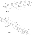
- the length L2 'of the exchange enclosure 16 is strictly greater than the length L1' of the mixing enclosure 15, so as to create a ceiling 30 at said enclosure d 'exchange 16, said ceiling 30 comprising at least one longitudinal opening 31 suitable for the passage of fluids from said exchange chamber 16 to said distribution zone (C).
- Such an arrangement of the device according to the invention makes it possible, by creating a longitudinal opening 31 on the exchange enclosure, to better manage the flow of fluids, in particular of the gas type, leaving the exchange enclosure 16, and therefore to limit the impact of the flow of fluids on the distribution plate 12 of the distribution zone (C).
- the ratio between the length L1 ′ of the mixing chamber 15 and the length L2 ′ of the exchange chamber 16 is between 0.1 and 0.9, preferably between 0.3 and 0, 9.
- the ratio between the surface of the ceiling 30 and the surface of the longitudinal opening (s) 31 is between 0.2 and 1, preferably between 0.3 and 0.8.
- the ratio between the surface of the ceiling 30 and the surface of said longitudinal opening 31 is equal to 1, which means that the ceiling 30 is completely open to the distribution zone (C) .
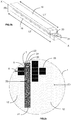
- the device according to the invention advantageously comprises a plurality of horizontal panels 33 (cf. figure 2c ) located in the distribution area (C), below the opening 31 of the ceiling 30 of the exchange enclosure 16, but above the chimneys 13 or placed on the chimneys 13 of the distribution plate 12 ( cf. figure 2d ).
- Said horizontal panels 33 are preferably spaced from each other by a distance of between 0 and 5 cm, preferably between 0.5 and 1 cm, so as to allow the flow of fluids to the space between the panels.
- said horizontal panels 33 are located at a height of between 0 and 10 cm from the chimneys 13 of the distribution plate 12.
- the horizontal panels 33 When the horizontal panels are placed on the chimneys of the distribution plate, the latter are configured so as to allow the passage of gas-type fluids, for example by having a bevelled end.
- the horizontal panels 33 occupy an area of between 5 and 95% relative to the radial area of the reactor, preferably between 5 and 30%.
- Such an arrangement of the device according to the invention makes it possible to guarantee good mixing efficiency of the fluids without, however, causing an increase in the size of said device.
- the horizontal panels 33 comprise a plurality of perforations allowing the flow of fluids towards the space located between the horizontal panels 33 and the distribution plate 12. For each horizontal panel 33, the area occupied by said perforations is between 1 and 20% by area, preferably between 2 and 5% by area, relative to the total area of the horizontal panel 33.
- the exchange enclosure 16 can also comprise on its side walls 20 side passage sections 17 suitable for the passage of fluids from the mixing zone (B) to the distribution zone (C).
- the device may optionally include at least one side deflector 32 (cf. figure 3 ) located at the level of said distribution zone (C), facing at least one side passage section 17.
- the device comprises at least one pair of side deflectors 32 located in the distribution zone (C) on either side of the exchange enclosure 16 facing the side passage sections 17.
- the mixing zone (B), ie the mixing chamber 15 and the exchange chamber 16, is off-center with respect to the center of the distribution zone (C) (cf. figure 3 ).
- This offset of the mixing zone with respect to the center of the distribution zone has the advantage of facilitating the inspection and maintenance operations of the device.
- This particular configuration of the device divides the distribution plate 12 into two zones Z1 and Z2 of different surfaces, with Z1 ⁇ Z2 (cf. figure 3 ).
- the zones Z1 and Z2 are defined respectively as the surface of the distribution plate 12 between the side wall 20 of the exchange chamber 16, the periphery of the chamber 1 of the reactor, and respectively the two axes AA 'and BB '(cf.
- the flow rate of the fluids passing through the lateral passage sections 17 of the exchange enclosure 16 was adapted as a function of the ratio R.
- Sp be the total area of the side passage sections 17 of the side wall 20 facing the zone Z1 of the distribution plate 12 ( ie located on the side where the surface of the distribution plate is the smallest) and Sg the total surface of the side passage sections 17 of the side wall 20 facing the zone Z2 of the distribution plate 12 (ie on the side where the surface of the distribution tray is the largest).
- the ratio R 'between the Sp / Sg surfaces is between 0.5 and 1.5, preferably between 0.6 and 1 , 4.
- the two zones Z1 and Z2 of the distribution plate 12 are supplied with identical fluid flow rates, which results in poor distribution. fluids, and therefore induces a significant loss in the performance of fluid distribution on the distribution plate 12.
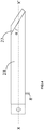
- the bottom 23 of the mixing chamber 15 may include an end edge 27 of bevelled shape and forms an angle ⁇ with respect to the longitudinal axis XX 'of the mixing chamber 15 of between 20 ° and 70 °, preferably between 30 ° and 60 ° and even more preferably between 30 ° and 45 °.
- Such a shape of the end edge of the mixing chamber 15 makes it possible to create a flow of the fluids of the vortex type at the level of the opening 18 , which has the effect of improving the efficiency of mixing the fluids, in particular. by allowing a mixture of the fluid flow lines located on either side of the side walls of the mixing chamber 15.
- such a configuration of the mixing chamber 15 has the effect of reducing the speed fluids between the mixing chamber and the exchange chamber. By decreasing the fluid velocities at the level, the pressure drop is minimized.
- the ends of the mixing 15 and exchange 16 enclosures are not in contact with the wall of the reactor enclosure 1, so as to allow the circulation of fluids on the distribution plate 12 on either side.
- mixing 15 and exchange enclosures 16 are not in contact with the wall of the reactor enclosure 1, so as to allow the circulation of fluids on the distribution plate 12 on either side.
- mixing 15 and exchange enclosures 16 constitute a single piece.
- the total cumulative height H2 of said mixing chamber 15 and said exchange chamber 16 is between 200 and 1500 mm, preferably between 200 and 800 mm, more preferably between 300 and 750 mm, and even more preferably between 350 and 700 mm.
- the width “L” (cf. figure 2a ) of the exchange enclosure 16 is between 200 and 1100 mm, preferably between 200 and 800 mm, more preferably between 250 and 700 mm, and even more preferably between 300 and 600 mm.
- the volume ratio (in%) between the exchange enclosure (s) 16 and the mixing enclosure 15 is between 5 and 60%, preferably between 10 and 60%, and even more preferably between 15 and 40%.
- the exchange enclosure 16 is placed directly on the distribution plate 12 (as shown for example in figure 1 for example). In another embodiment (not shown in the figures), the exchange enclosure 16 is located at a distance "d" from said distribution plate 12, preferably between 20 and 150 mm, and more preferably between 30 and 80 mm.
- the space between the distribution plate 12 and the exchange chamber 16 allows the distribution of fluids over the entire surface of the distributor plate 12, and therefore makes it possible to homogenize the distribution of the mixture of fluids over the entire section of the reactor. above the catalyst bed 14 located downstream of the mixing and distribution device, in the direction of the circulation of the fluids (cf. in particular figure 1 ).
- the exchange enclosure 16 can comprise in its lower part longitudinal passage sections so that the mixture of fluids can flow towards the distribution plate 12.
- the number, the shape and the size of the longitudinal passage sections are chosen such that a minor fraction of the flow of fluid mixture passes through said longitudinal passage sections.
- the longitudinal passage sections can equally well take the form of orifices and / or slots.
- the dispersion system 19 (cf. figure 1 ) can comprise one or more dispersion devices which can be associated with each chimney 13, be in common with several chimneys 13, or even be in common with all the chimneys 13 of the distribution plate 12.
- Each dispersion device 19 has a substantially flat and horizontal geometry, but may have a perimeter of any shape.
- each dispersing device 19 can be located at different heights.
- said dispersion device is in the form of grids, and / or may optionally include deflectors.
- the axis of the grid (s) 19 is preferably perpendicular to the longitudinal axis of the reactor enclosure in order to improve the distribution of the mixture of fluids over the entire radial section of the reactor enclosure.
- the distance separating the dispersion system from the bed of granular solids located immediately below is chosen so as to keep the state of mixing of the gas and liquid phases as much as possible as it is at the outlet of the chimneys 13.
- the distance between the distribution plate 12 and catalyst bed 14 located below said distribution plate is between 50 and 400 mm, preferably between 100 and 300 mm.
- the distance between the distribution plate 12 and said dispersing device 19 is between 0 and 400 mm, preferably between 0 and 300 mm.
- the distribution plate 12 is placed on the dispersion device 19.
Landscapes
- Chemical & Material Sciences (AREA)
- Organic Chemistry (AREA)
- Chemical Kinetics & Catalysis (AREA)
- Devices And Processes Conducted In The Presence Of Fluids And Solid Particles (AREA)
Priority Applications (1)
| Application Number | Priority Date | Filing Date | Title |
|---|---|---|---|
| PL18778922T PL3694639T3 (pl) | 2017-10-12 | 2018-09-28 | Urządzenie do mieszania i rozprowadzania z otworem wzdłużnym |
Applications Claiming Priority (2)
| Application Number | Priority Date | Filing Date | Title |
|---|---|---|---|
| FR1759551A FR3072306B1 (fr) | 2017-10-12 | 2017-10-12 | Dispositif de melange et de distribution avec ouverture longitudinale |
| PCT/EP2018/076546 WO2019072601A1 (fr) | 2017-10-12 | 2018-09-28 | Dispositif de melange et de distribution avec ouverture longitudinale |
Publications (2)
| Publication Number | Publication Date |
|---|---|
| EP3694639A1 EP3694639A1 (fr) | 2020-08-19 |
| EP3694639B1 true EP3694639B1 (fr) | 2021-05-19 |
Family
ID=60765846
Family Applications (1)
| Application Number | Title | Priority Date | Filing Date |
|---|---|---|---|
| EP18778922.7A Active EP3694639B1 (fr) | 2017-10-12 | 2018-09-28 | Dispositif de melange et de distribution avec ouverture longitudinale |
Country Status (11)
| Country | Link |
|---|---|
| US (1) | US11117109B2 (pl) |
| EP (1) | EP3694639B1 (pl) |
| KR (1) | KR102574012B1 (pl) |
| CN (1) | CN111246935B (pl) |
| BR (1) | BR112020002219B1 (pl) |
| ES (1) | ES2884798T3 (pl) |
| FR (1) | FR3072306B1 (pl) |
| PL (1) | PL3694639T3 (pl) |
| RU (1) | RU2759813C2 (pl) |
| SA (1) | SA520411746B1 (pl) |
| WO (1) | WO2019072601A1 (pl) |
Family Cites Families (14)
| Publication number | Priority date | Publication date | Assignee | Title |
|---|---|---|---|---|
| FR2782657B1 (fr) * | 1998-09-02 | 2000-09-29 | Inst Francais Du Petrole | Systeme distributeur-collecteur de fluides et son procede |
| FR2824495B1 (fr) | 2001-05-09 | 2005-03-04 | Inst Francais Du Petrole | Enceinte reactionnelle de forme allongee le long d'un axe contenant au moins un lit de catalyseur solide et au moins une boite de contact, de melange et de trempe |
| FR2853260B1 (fr) * | 2003-04-02 | 2005-05-06 | Inst Francais Du Petrole | Dispositif ameliore de melange et de distribution d'une phase gaz et d'une phase liquide alimentant un lit granulaire |
| JP5276098B2 (ja) * | 2007-06-21 | 2013-08-28 | ビーエーエスエフ ソシエタス・ヨーロピア | 触媒床上で液相及び気相の三相反応を実行するための反応器 |
| FR2952835B1 (fr) | 2009-11-20 | 2011-12-09 | Inst Francais Du Petrole | Dispositif compact de melange de fluides dans un reacteur a ecoulement descendant |
| FR2980720B1 (fr) * | 2011-09-30 | 2013-09-06 | Ifp Energies Now | Plateau distributeur pour la distribution d'un melange polyphasique avec cheminees inclinees en peripherie. |
| CN103084084B (zh) * | 2011-11-02 | 2015-09-23 | 中国石油化工股份有限公司 | 一种液体收集、混合和均布的设备 |
| WO2014210276A1 (en) * | 2013-06-28 | 2014-12-31 | Uop Llc | Fluid mixing and distribution device and method for multibed reactors |
| US9321023B2 (en) * | 2013-06-28 | 2016-04-26 | Uop Llc | Fluid mixing and distribution device and method for multibed reactors |
| EP2918332A1 (en) * | 2014-03-14 | 2015-09-16 | Morten Müller Ltd., ApS | Scale collection and predistribution tray for vessel with downwards two-phase flow |
| CN204294209U (zh) * | 2014-08-28 | 2015-04-29 | 中国石油化工股份有限公司 | 一种流体分布设备 |
| FR3026316B1 (fr) * | 2014-09-29 | 2016-10-28 | Ifp Energies Now | Dispositif compact de melange de fluides |
| FR3034323B1 (fr) * | 2015-04-01 | 2017-03-17 | Ifp Energies Now | Dispositif de melange et de distribution avec zones de melange et d'echange |
| CN206244797U (zh) * | 2016-12-09 | 2017-06-13 | 陆飞浩 | 气升式发酵罐的复合进气装置 |
-
2017
- 2017-10-12 FR FR1759551A patent/FR3072306B1/fr not_active Expired - Fee Related
-
2018
- 2018-09-28 CN CN201880066471.9A patent/CN111246935B/zh active Active
- 2018-09-28 US US16/755,317 patent/US11117109B2/en active Active
- 2018-09-28 BR BR112020002219-5A patent/BR112020002219B1/pt active IP Right Grant
- 2018-09-28 RU RU2020115163A patent/RU2759813C2/ru active
- 2018-09-28 ES ES18778922T patent/ES2884798T3/es active Active
- 2018-09-28 WO PCT/EP2018/076546 patent/WO2019072601A1/fr not_active Ceased
- 2018-09-28 KR KR1020207007260A patent/KR102574012B1/ko active Active
- 2018-09-28 EP EP18778922.7A patent/EP3694639B1/fr active Active
- 2018-09-28 PL PL18778922T patent/PL3694639T3/pl unknown
-
2020
- 2020-04-09 SA SA520411746A patent/SA520411746B1/ar unknown
Also Published As
| Publication number | Publication date |
|---|---|
| CN111246935B (zh) | 2022-04-19 |
| RU2020115163A3 (pl) | 2021-11-12 |
| KR20200068648A (ko) | 2020-06-15 |
| US20210197159A1 (en) | 2021-07-01 |
| FR3072306B1 (fr) | 2019-10-18 |
| PL3694639T3 (pl) | 2021-12-20 |
| SA520411746B1 (ar) | 2023-11-12 |
| RU2759813C2 (ru) | 2021-11-18 |
| BR112020002219A2 (pt) | 2020-07-28 |
| BR112020002219B1 (pt) | 2023-10-03 |
| RU2020115163A (ru) | 2021-11-12 |
| CN111246935A (zh) | 2020-06-05 |
| ES2884798T3 (es) | 2021-12-13 |
| CA3071466A1 (fr) | 2019-04-18 |
| KR102574012B1 (ko) | 2023-09-01 |
| US11117109B2 (en) | 2021-09-14 |
| WO2019072601A1 (fr) | 2019-04-18 |
| EP3694639A1 (fr) | 2020-08-19 |
| FR3072306A1 (fr) | 2019-04-19 |
Similar Documents
| Publication | Publication Date | Title |
|---|---|---|
| EP3075444B1 (fr) | Dispositif de melange et de distribution avec zones de melange et d echange | |
| EP3075443B1 (fr) | Dispositf de mélange et de distribution comprenant un plâteau de distribution avec ouvertures périphériques | |
| FR3001899A1 (fr) | Dispositif d'injection et de melange de fluides dans un reacteur a ecoulement descendant. | |
| CA2343845C (fr) | Dispositif de distribution d'un melange polyphasique sur un lit de solide granulaire comportant un element brise-jet poreux | |
| FR3050658A1 (fr) | Dispositif de melange et de distribution avec zones de melange et d'echange et deflecteurs. | |
| EP1446221B1 (fr) | Dispositif de distribution d'un melange polyphasique sur un lit de solide granulaire comportant un element brise jet poreux a rebords | |
| WO2013017804A1 (fr) | Plateau distributeur d'un gaz et d'un liquide, reacteur equipe d'un tel plateau et utilisation dudit plateau | |
| EP3277417A1 (fr) | Dispositif compact de melange et de distribution combine de fluides pour un reacteur catalytique | |
| EP2151277B1 (fr) | Réacteur gaz-liquide à écoulement co-courant ascendant avec plateau distributeur | |
| EP2647425B1 (fr) | Réacteur catalytique avec dispositif de trempe muni d'une injection tangentielle d'un fluide de trempe | |
| WO2006097590A2 (fr) | Dispositif pour le melange et la repartition d'un gaz et d'un liquide en amont d'un lit granulaire | |
| EP3618947B1 (fr) | Nouveau dispositif de distribution de mélange polyphasique dans une enceinte comportant un milieu fluidise | |
| FR2917306A1 (fr) | Enceinte contenant un lit granulaire et une distribution d'une phase gazeuse et d'une phase liquide circulant en un ecoulement ascendant dans cette enceinte | |
| WO2016050409A1 (fr) | Dispositif compact de mélange de fluides | |
| FR2826594A1 (fr) | Boite de contact, de melange et de trempe de fluides comportant au moins une sortie annulaire peripherique et enceinte reactionnelle de forme allongee le long d'un axe comprenant ladite boite | |
| EP3694639B1 (fr) | Dispositif de melange et de distribution avec ouverture longitudinale | |
| EP3536398B1 (fr) | Dispositif de melange d'un fluide pour un lit catalytique | |
| CA3071466C (fr) | Dispositif de melange et de distribution avec ouverture longitudinale | |
| FR2824495A1 (fr) | Enceinte reactionnelle de forme allongee le long d'un axe contenant au moins un lit de catalyseur solide et au moins une boite de contact, de melange et de trempe | |
| FR3066411B1 (fr) | Dispositif de melange et de distribution avec systeme d'equilibrage des fluides | |
| FR3066410B1 (fr) | Dispositif de melange et de distribution avec zone de retournement | |
| FR3066409B1 (fr) | Dispositif de melange et de distribution avec injection de fluide de trempe ameliore | |
| FR3083993A1 (fr) | Dispositif de melange et de distribution avec buse d'injection perfectionnee |
Legal Events
| Date | Code | Title | Description |
|---|---|---|---|
| STAA | Information on the status of an ep patent application or granted ep patent |
Free format text: STATUS: UNKNOWN |
|
| STAA | Information on the status of an ep patent application or granted ep patent |
Free format text: STATUS: THE INTERNATIONAL PUBLICATION HAS BEEN MADE |
|
| PUAI | Public reference made under article 153(3) epc to a published international application that has entered the european phase |
Free format text: ORIGINAL CODE: 0009012 |
|
| STAA | Information on the status of an ep patent application or granted ep patent |
Free format text: STATUS: REQUEST FOR EXAMINATION WAS MADE |
|
| 17P | Request for examination filed |
Effective date: 20200512 |
|
| AK | Designated contracting states |
Kind code of ref document: A1 Designated state(s): AL AT BE BG CH CY CZ DE DK EE ES FI FR GB GR HR HU IE IS IT LI LT LU LV MC MK MT NL NO PL PT RO RS SE SI SK SM TR |
|
| AX | Request for extension of the european patent |
Extension state: BA ME |
|
| DAV | Request for validation of the european patent (deleted) | ||
| DAX | Request for extension of the european patent (deleted) | ||
| GRAP | Despatch of communication of intention to grant a patent |
Free format text: ORIGINAL CODE: EPIDOSNIGR1 |
|
| STAA | Information on the status of an ep patent application or granted ep patent |
Free format text: STATUS: GRANT OF PATENT IS INTENDED |
|
| INTG | Intention to grant announced |
Effective date: 20210218 |
|
| GRAS | Grant fee paid |
Free format text: ORIGINAL CODE: EPIDOSNIGR3 |
|
| GRAA | (expected) grant |
Free format text: ORIGINAL CODE: 0009210 |
|
| STAA | Information on the status of an ep patent application or granted ep patent |
Free format text: STATUS: THE PATENT HAS BEEN GRANTED |
|
| AK | Designated contracting states |
Kind code of ref document: B1 Designated state(s): AL AT BE BG CH CY CZ DE DK EE ES FI FR GB GR HR HU IE IS IT LI LT LU LV MC MK MT NL NO PL PT RO RS SE SI SK SM TR |
|
| REG | Reference to a national code |
Ref country code: GB Ref legal event code: FG4D Free format text: NOT ENGLISH |
|
| REG | Reference to a national code |
Ref country code: CH Ref legal event code: EP |
|
| REG | Reference to a national code |
Ref country code: DE Ref legal event code: R096 Ref document number: 602018017426 Country of ref document: DE |
|
| REG | Reference to a national code |
Ref country code: AT Ref legal event code: REF Ref document number: 1393457 Country of ref document: AT Kind code of ref document: T Effective date: 20210615 |
|
| REG | Reference to a national code |
Ref country code: IE Ref legal event code: FG4D Free format text: LANGUAGE OF EP DOCUMENT: FRENCH |
|
| REG | Reference to a national code |
Ref country code: NL Ref legal event code: FP |
|
| REG | Reference to a national code |
Ref country code: LT Ref legal event code: MG9D |
|
| REG | Reference to a national code |
Ref country code: AT Ref legal event code: MK05 Ref document number: 1393457 Country of ref document: AT Kind code of ref document: T Effective date: 20210519 |
|
| PG25 | Lapsed in a contracting state [announced via postgrant information from national office to epo] |
Ref country code: FI Free format text: LAPSE BECAUSE OF FAILURE TO SUBMIT A TRANSLATION OF THE DESCRIPTION OR TO PAY THE FEE WITHIN THE PRESCRIBED TIME-LIMIT Effective date: 20210519 Ref country code: LT Free format text: LAPSE BECAUSE OF FAILURE TO SUBMIT A TRANSLATION OF THE DESCRIPTION OR TO PAY THE FEE WITHIN THE PRESCRIBED TIME-LIMIT Effective date: 20210519 Ref country code: HR Free format text: LAPSE BECAUSE OF FAILURE TO SUBMIT A TRANSLATION OF THE DESCRIPTION OR TO PAY THE FEE WITHIN THE PRESCRIBED TIME-LIMIT Effective date: 20210519 Ref country code: BG Free format text: LAPSE BECAUSE OF FAILURE TO SUBMIT A TRANSLATION OF THE DESCRIPTION OR TO PAY THE FEE WITHIN THE PRESCRIBED TIME-LIMIT Effective date: 20210819 Ref country code: AT Free format text: LAPSE BECAUSE OF FAILURE TO SUBMIT A TRANSLATION OF THE DESCRIPTION OR TO PAY THE FEE WITHIN THE PRESCRIBED TIME-LIMIT Effective date: 20210519 |
|
| PG25 | Lapsed in a contracting state [announced via postgrant information from national office to epo] |
Ref country code: PT Free format text: LAPSE BECAUSE OF FAILURE TO SUBMIT A TRANSLATION OF THE DESCRIPTION OR TO PAY THE FEE WITHIN THE PRESCRIBED TIME-LIMIT Effective date: 20210920 Ref country code: RS Free format text: LAPSE BECAUSE OF FAILURE TO SUBMIT A TRANSLATION OF THE DESCRIPTION OR TO PAY THE FEE WITHIN THE PRESCRIBED TIME-LIMIT Effective date: 20210519 Ref country code: SE Free format text: LAPSE BECAUSE OF FAILURE TO SUBMIT A TRANSLATION OF THE DESCRIPTION OR TO PAY THE FEE WITHIN THE PRESCRIBED TIME-LIMIT Effective date: 20210519 Ref country code: NO Free format text: LAPSE BECAUSE OF FAILURE TO SUBMIT A TRANSLATION OF THE DESCRIPTION OR TO PAY THE FEE WITHIN THE PRESCRIBED TIME-LIMIT Effective date: 20210819 Ref country code: LV Free format text: LAPSE BECAUSE OF FAILURE TO SUBMIT A TRANSLATION OF THE DESCRIPTION OR TO PAY THE FEE WITHIN THE PRESCRIBED TIME-LIMIT Effective date: 20210519 Ref country code: IS Free format text: LAPSE BECAUSE OF FAILURE TO SUBMIT A TRANSLATION OF THE DESCRIPTION OR TO PAY THE FEE WITHIN THE PRESCRIBED TIME-LIMIT Effective date: 20210919 Ref country code: GR Free format text: LAPSE BECAUSE OF FAILURE TO SUBMIT A TRANSLATION OF THE DESCRIPTION OR TO PAY THE FEE WITHIN THE PRESCRIBED TIME-LIMIT Effective date: 20210820 |
|
| REG | Reference to a national code |
Ref country code: ES Ref legal event code: FG2A Ref document number: 2884798 Country of ref document: ES Kind code of ref document: T3 Effective date: 20211213 |
|
| PG25 | Lapsed in a contracting state [announced via postgrant information from national office to epo] |
Ref country code: SK Free format text: LAPSE BECAUSE OF FAILURE TO SUBMIT A TRANSLATION OF THE DESCRIPTION OR TO PAY THE FEE WITHIN THE PRESCRIBED TIME-LIMIT Effective date: 20210519 Ref country code: EE Free format text: LAPSE BECAUSE OF FAILURE TO SUBMIT A TRANSLATION OF THE DESCRIPTION OR TO PAY THE FEE WITHIN THE PRESCRIBED TIME-LIMIT Effective date: 20210519 Ref country code: DK Free format text: LAPSE BECAUSE OF FAILURE TO SUBMIT A TRANSLATION OF THE DESCRIPTION OR TO PAY THE FEE WITHIN THE PRESCRIBED TIME-LIMIT Effective date: 20210519 Ref country code: CZ Free format text: LAPSE BECAUSE OF FAILURE TO SUBMIT A TRANSLATION OF THE DESCRIPTION OR TO PAY THE FEE WITHIN THE PRESCRIBED TIME-LIMIT Effective date: 20210519 Ref country code: RO Free format text: LAPSE BECAUSE OF FAILURE TO SUBMIT A TRANSLATION OF THE DESCRIPTION OR TO PAY THE FEE WITHIN THE PRESCRIBED TIME-LIMIT Effective date: 20210519 Ref country code: SM Free format text: LAPSE BECAUSE OF FAILURE TO SUBMIT A TRANSLATION OF THE DESCRIPTION OR TO PAY THE FEE WITHIN THE PRESCRIBED TIME-LIMIT Effective date: 20210519 |
|
| REG | Reference to a national code |
Ref country code: DE Ref legal event code: R097 Ref document number: 602018017426 Country of ref document: DE |
|
| PLBE | No opposition filed within time limit |
Free format text: ORIGINAL CODE: 0009261 |
|
| STAA | Information on the status of an ep patent application or granted ep patent |
Free format text: STATUS: NO OPPOSITION FILED WITHIN TIME LIMIT |
|
| 26N | No opposition filed |
Effective date: 20220222 |
|
| REG | Reference to a national code |
Ref country code: CH Ref legal event code: PL |
|
| REG | Reference to a national code |
Ref country code: BE Ref legal event code: MM Effective date: 20210930 |
|
| PG25 | Lapsed in a contracting state [announced via postgrant information from national office to epo] |
Ref country code: IS Free format text: LAPSE BECAUSE OF FAILURE TO SUBMIT A TRANSLATION OF THE DESCRIPTION OR TO PAY THE FEE WITHIN THE PRESCRIBED TIME-LIMIT Effective date: 20210919 Ref country code: MC Free format text: LAPSE BECAUSE OF FAILURE TO SUBMIT A TRANSLATION OF THE DESCRIPTION OR TO PAY THE FEE WITHIN THE PRESCRIBED TIME-LIMIT Effective date: 20210519 Ref country code: AL Free format text: LAPSE BECAUSE OF FAILURE TO SUBMIT A TRANSLATION OF THE DESCRIPTION OR TO PAY THE FEE WITHIN THE PRESCRIBED TIME-LIMIT Effective date: 20210519 |
|
| PG25 | Lapsed in a contracting state [announced via postgrant information from national office to epo] |
Ref country code: LU Free format text: LAPSE BECAUSE OF NON-PAYMENT OF DUE FEES Effective date: 20210928 Ref country code: IT Free format text: LAPSE BECAUSE OF FAILURE TO SUBMIT A TRANSLATION OF THE DESCRIPTION OR TO PAY THE FEE WITHIN THE PRESCRIBED TIME-LIMIT Effective date: 20210519 Ref country code: IE Free format text: LAPSE BECAUSE OF NON-PAYMENT OF DUE FEES Effective date: 20210928 Ref country code: BE Free format text: LAPSE BECAUSE OF NON-PAYMENT OF DUE FEES Effective date: 20210930 |
|
| PG25 | Lapsed in a contracting state [announced via postgrant information from national office to epo] |
Ref country code: LI Free format text: LAPSE BECAUSE OF NON-PAYMENT OF DUE FEES Effective date: 20210930 Ref country code: CH Free format text: LAPSE BECAUSE OF NON-PAYMENT OF DUE FEES Effective date: 20210930 |
|
| GBPC | Gb: european patent ceased through non-payment of renewal fee |
Effective date: 20220928 |
|
| PG25 | Lapsed in a contracting state [announced via postgrant information from national office to epo] |
Ref country code: CY Free format text: LAPSE BECAUSE OF FAILURE TO SUBMIT A TRANSLATION OF THE DESCRIPTION OR TO PAY THE FEE WITHIN THE PRESCRIBED TIME-LIMIT Effective date: 20210519 |
|
| PG25 | Lapsed in a contracting state [announced via postgrant information from national office to epo] |
Ref country code: HU Free format text: LAPSE BECAUSE OF FAILURE TO SUBMIT A TRANSLATION OF THE DESCRIPTION OR TO PAY THE FEE WITHIN THE PRESCRIBED TIME-LIMIT; INVALID AB INITIO Effective date: 20180928 |
|
| PG25 | Lapsed in a contracting state [announced via postgrant information from national office to epo] |
Ref country code: GB Free format text: LAPSE BECAUSE OF NON-PAYMENT OF DUE FEES Effective date: 20220928 |
|
| PG25 | Lapsed in a contracting state [announced via postgrant information from national office to epo] |
Ref country code: MK Free format text: LAPSE BECAUSE OF FAILURE TO SUBMIT A TRANSLATION OF THE DESCRIPTION OR TO PAY THE FEE WITHIN THE PRESCRIBED TIME-LIMIT Effective date: 20210519 |
|
| PG25 | Lapsed in a contracting state [announced via postgrant information from national office to epo] |
Ref country code: MT Free format text: LAPSE BECAUSE OF FAILURE TO SUBMIT A TRANSLATION OF THE DESCRIPTION OR TO PAY THE FEE WITHIN THE PRESCRIBED TIME-LIMIT Effective date: 20210519 |
|
| PGFP | Annual fee paid to national office [announced via postgrant information from national office to epo] |
Ref country code: DE Payment date: 20250926 Year of fee payment: 8 |
|
| PGFP | Annual fee paid to national office [announced via postgrant information from national office to epo] |
Ref country code: NL Payment date: 20250925 Year of fee payment: 8 Ref country code: TR Payment date: 20250915 Year of fee payment: 8 Ref country code: PL Payment date: 20250916 Year of fee payment: 8 |
|
| PGFP | Annual fee paid to national office [announced via postgrant information from national office to epo] |
Ref country code: FR Payment date: 20250925 Year of fee payment: 8 |
|
| PGFP | Annual fee paid to national office [announced via postgrant information from national office to epo] |
Ref country code: ES Payment date: 20251010 Year of fee payment: 8 |