EP3694595B1 - An rfid tag insertion cartridge and an rfid tag insertion tool - Google Patents
An rfid tag insertion cartridge and an rfid tag insertion tool Download PDFInfo
- Publication number
- EP3694595B1 EP3694595B1 EP18867114.3A EP18867114A EP3694595B1 EP 3694595 B1 EP3694595 B1 EP 3694595B1 EP 18867114 A EP18867114 A EP 18867114A EP 3694595 B1 EP3694595 B1 EP 3694595B1
- Authority
- EP
- European Patent Office
- Prior art keywords
- rfid tag
- tag insertion
- cartridge
- fitting
- needle
- Prior art date
- Legal status (The legal status is an assumption and is not a legal conclusion. Google has not performed a legal analysis and makes no representation as to the accuracy of the status listed.)
- Active
Links
Images

Classifications
-
- A—HUMAN NECESSITIES
- A01—AGRICULTURE; FORESTRY; ANIMAL HUSBANDRY; HUNTING; TRAPPING; FISHING
- A01K—ANIMAL HUSBANDRY; AVICULTURE; APICULTURE; PISCICULTURE; FISHING; REARING OR BREEDING ANIMALS, NOT OTHERWISE PROVIDED FOR; NEW BREEDS OF ANIMALS
- A01K11/00—Marking of animals
- A01K11/006—Automatic identification systems for animals, e.g. electronic devices, transponders for animals
-
- A—HUMAN NECESSITIES
- A61—MEDICAL OR VETERINARY SCIENCE; HYGIENE
- A61B—DIAGNOSIS; SURGERY; IDENTIFICATION
- A61B17/00—Surgical instruments, devices or methods
- A61B17/34—Trocars; Puncturing needles
-
- A—HUMAN NECESSITIES
- A61—MEDICAL OR VETERINARY SCIENCE; HYGIENE
- A61B—DIAGNOSIS; SURGERY; IDENTIFICATION
- A61B90/00—Instruments, implements or accessories specially adapted for surgery or diagnosis and not covered by any of the groups A61B1/00 - A61B50/00, e.g. for luxation treatment or for protecting wound edges
- A61B90/03—Automatic limiting or abutting means, e.g. for safety
-
- A—HUMAN NECESSITIES
- A61—MEDICAL OR VETERINARY SCIENCE; HYGIENE
- A61D—VETERINARY INSTRUMENTS, IMPLEMENTS, TOOLS, OR METHODS
- A61D7/00—Devices or methods for introducing solid, liquid or gaseous remedies or other materials into or onto the bodies of animals
-
- A—HUMAN NECESSITIES
- A61—MEDICAL OR VETERINARY SCIENCE; HYGIENE
- A61M—DEVICES FOR INTRODUCING MEDIA INTO, OR ONTO, THE BODY; DEVICES FOR TRANSDUCING BODY MEDIA OR FOR TAKING MEDIA FROM THE BODY; DEVICES FOR PRODUCING OR ENDING SLEEP OR STUPOR
- A61M37/00—Other apparatus for introducing media into the body; Percutany, i.e. introducing medicines into the body by diffusion through the skin
- A61M37/0069—Devices for implanting pellets, e.g. markers or solid medicaments
-
- G—PHYSICS
- G06—COMPUTING OR CALCULATING; COUNTING
- G06K—GRAPHICAL DATA READING; PRESENTATION OF DATA; RECORD CARRIERS; HANDLING RECORD CARRIERS
- G06K19/00—Record carriers for use with machines and with at least a part designed to carry digital markings
- G06K19/06—Record carriers for use with machines and with at least a part designed to carry digital markings characterised by the kind of the digital marking, e.g. shape, nature, code
- G06K19/067—Record carriers with conductive marks, printed circuits or semiconductor circuit elements, e.g. credit or identity cards also with resonating or responding marks without active components
- G06K19/07—Record carriers with conductive marks, printed circuits or semiconductor circuit elements, e.g. credit or identity cards also with resonating or responding marks without active components with integrated circuit chips
- G06K19/077—Constructional details, e.g. mounting of circuits in the carrier
- G06K19/07749—Constructional details, e.g. mounting of circuits in the carrier the record carrier being capable of non-contact communication, e.g. constructional details of the antenna of a non-contact smart card
- G06K19/07758—Constructional details, e.g. mounting of circuits in the carrier the record carrier being capable of non-contact communication, e.g. constructional details of the antenna of a non-contact smart card arrangements for adhering the record carrier to further objects or living beings, functioning as an identification tag
-
- A—HUMAN NECESSITIES
- A61—MEDICAL OR VETERINARY SCIENCE; HYGIENE
- A61B—DIAGNOSIS; SURGERY; IDENTIFICATION
- A61B17/00—Surgical instruments, devices or methods
- A61B17/34—Trocars; Puncturing needles
- A61B17/3468—Trocars; Puncturing needles for implanting or removing devices, e.g. prostheses, implants, seeds, wires
-
- A—HUMAN NECESSITIES
- A61—MEDICAL OR VETERINARY SCIENCE; HYGIENE
- A61B—DIAGNOSIS; SURGERY; IDENTIFICATION
- A61B17/00—Surgical instruments, devices or methods
- A61B2017/00367—Details of actuation of instruments, e.g. relations between pushing buttons, or the like, and activation of the tool, working tip, or the like
- A61B2017/00371—Multiple actuation, e.g. pushing of two buttons, or two working tips becoming operational
-
- A—HUMAN NECESSITIES
- A61—MEDICAL OR VETERINARY SCIENCE; HYGIENE
- A61B—DIAGNOSIS; SURGERY; IDENTIFICATION
- A61B90/00—Instruments, implements or accessories specially adapted for surgery or diagnosis and not covered by any of the groups A61B1/00 - A61B50/00, e.g. for luxation treatment or for protecting wound edges
- A61B90/03—Automatic limiting or abutting means, e.g. for safety
- A61B2090/033—Abutting means, stops, e.g. abutting on tissue or skin
- A61B2090/034—Abutting means, stops, e.g. abutting on tissue or skin abutting on parts of the device itself
-
- A—HUMAN NECESSITIES
- A61—MEDICAL OR VETERINARY SCIENCE; HYGIENE
- A61B—DIAGNOSIS; SURGERY; IDENTIFICATION
- A61B90/00—Instruments, implements or accessories specially adapted for surgery or diagnosis and not covered by any of the groups A61B1/00 - A61B50/00, e.g. for luxation treatment or for protecting wound edges
- A61B90/39—Markers, e.g. radio-opaque or breast lesions markers
- A61B2090/3987—Applicators for implanting markers
-
- A—HUMAN NECESSITIES
- A61—MEDICAL OR VETERINARY SCIENCE; HYGIENE
- A61B—DIAGNOSIS; SURGERY; IDENTIFICATION
- A61B90/00—Instruments, implements or accessories specially adapted for surgery or diagnosis and not covered by any of the groups A61B1/00 - A61B50/00, e.g. for luxation treatment or for protecting wound edges
- A61B90/39—Markers, e.g. radio-opaque or breast lesions markers
-
- A—HUMAN NECESSITIES
- A61—MEDICAL OR VETERINARY SCIENCE; HYGIENE
- A61B—DIAGNOSIS; SURGERY; IDENTIFICATION
- A61B90/00—Instruments, implements or accessories specially adapted for surgery or diagnosis and not covered by any of the groups A61B1/00 - A61B50/00, e.g. for luxation treatment or for protecting wound edges
- A61B90/90—Identification means for patients or instruments, e.g. tags
- A61B90/98—Identification means for patients or instruments, e.g. tags using electromagnetic means, e.g. transponders
Definitions
- the disclosure herein generally relates to an RFID tag insertion cartridge and an RFID tag insertion tool.
- Radio frequency identification (“RFID”) tags can be implanted in an animal for identifying the animal, for example.
- the procedure to implant the RFID tag may require two highly skilled persons and can take many minutes to complete. An easier way to implant RFID tags that can be performed by less skilled persons quickly and safely is desirable.
- US 2005/234475 A1 describes a lancet for injection of an RFID Tag.
- the RFID tag insertion cartridge comprises a hollow needle in which an RFID tag is disposed.
- the RFID tag insertion cartridge comprises a carriage that is movably mounted and to which the hollow needle is attached for withdrawing the needle.
- the RFID tag insertion cartridge comprises a stop pin disposed in the hollow needle for stopping an inward movement of the RFID tag when the needle is withdrawn and so eject the RFID tag.
- An embodiment comprises a fitting for removable attachment to an RFID tag insertion tool operable to move the carriage.
- the fitting may be configured for uniquely orientating the RFID insertion cartridge with respect to the RFID tag insertion tool when attached thereto.
- the fitting may comprise at least one of a plurality of different diameter radial pins and a plurality of different width slots for receiving the plurality of different diameter radial pins.
- the fitting may comprise a bayonet fitting.
- an end of the stop pin is for abutting the RFID tag.
- Another end of the stop pin may comprise a hook.
- the carriage comprises a proximal end configured to be engagingly received by a distal end of the fitting for retaining the needle within the housing when so withdrawn.
- An embodiment comprises a housing comprising a linear bearing surface in contact with a plurality of protruding linear bearing pads of the carriage.
- the RFID tag insertion tool comprises an actuator that is user operable and a transmission assembly operationally coupled to the actuator.
- the transmission assembly comprises a coupler configured to couple to an RFID insertion cartridge and when so coupled transmit movement of the actuator to a needle of the RFID tag insertion cartridge.
- the RFID tag insertion tool comprises a biasing element arranged to inwardly bias the coupler.
- the transmission assembly comprises a displacement multiplier.
- the displacement multiplier may comprise a pinion arranged to move with the actuator.
- the displacement multiplier comprises a fixed rack and a translatably mounted rack that meshes with the pinion.
- An embodiment comprises a housing in which the fixed rack is fixed.
- An embodiment comprises a user releasable catch for outwardly retaining the coupling.
- An embodiment comprises a fitting for removable attachment of the RFID tag insertion tool.
- the fitting may be configured for uniquely orientating the RFID insertion cartridge with respect to the RFID tag insertion tool when attached thereto.
- the fitting may comprise at least one of a plurality of different diameter radial pins and a plurality of different width slots for receiving the plurality of different diameter radial pins.
- the fitting may comprise a bayonet fitting.
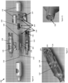
- FIG 1 shows a perspective view of an embodiment of an RFID tag insertion cartridge ("cartridge") generally indicated by the numeral 10.
- the cartridge 10 comprises a hollow needle 12 in which an RFID tag is disposed (and so hidden from view).
- the cartridge 10 comprises an optional housing 16 in the form of a shell that is shown transparently.
- the cartridge 10 comprises a carriage 14 that is movably mounted and to which the hollow needle 12 is attached for withdrawing the needle.
- Figure 2 shows a top view of the carriage 14 and needle 12 attached thereto.
- the cartridge 10 comprises a stop pin 18 disposed in the hollow needle 12 for stopping an inward movement of the RFID tag when the needle 12 is withdrawn and so eject the RFID tag.
- the RFID tag insertion cartridge 10 comprising a fitting 20 for removable attachment to an RFID tag insertion tool operable to move the carriage 14.
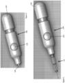
- Figure 3 shows a perspective view of an embodiment of an RFID tag insertion tool 100.
- Figure 4 shows a perspective view of the RFID tag insertion cartridge 10 attached to the RFID tag insertion tool 100.
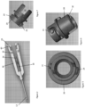
- Figures 5, 6 and 7 respectively show an end-on view, a perspective view and a side view of the fitting 20.
- the fitting 20 is configured for uniquely orientating the RFID insertion cartridge 10 with respect to the RFID tag insertion tool 100 when attached thereto.
- the fitting 20 comprises a plurality of different diameter radial pins 22,24 that are received by a plurality of different width slots defined by the RFID insertion tools 100.
- the fitting 20 defines the slots and the RFID insertion tool comprises the radial pins.
- the fitting 20 comprises a bayonet fitting, but in alternative embodiment may comprise a screw fitting or generally any suitable form of fitting.
- An end of the stop pin 18 is disposed in the hollow needle 12 (and so hidden) for abutting the RFID tag therein.
- Another end 26 of the stop pin 18 comprises a hook.
- the carriage 14 comprises a proximal end 28 configured to be engagingly received by the distal end 30 of the fitting 20 for retaining the needle 12 within the shell when so withdrawn.
- the proximal end 28 is received into at least one slot 32 defined by the fitting 20.
- a friction fit between the proximal end 28 of the carriage 14 and the distal end of the fitting 20 holds the needle to the fitting.
- the proximal end 28 of the carriage 14 comprises at least one, and in this embodiment a plurality of friction elements 38 in the form of side-wall engaging protrusions 40,42 for the frictional fit.
- the housing 12 comprises a linear bearing surface 34 in contact with the carriage 14.
- the housing may be replaced with a cage or framework with the linear bearing.
- the linear bearing surface 34 may be replaced with a roller bearing, or generally any suitable form of bearing.
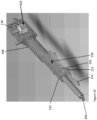
- FIG 8 shows an exploded perspective view of the RFID tag insertion tool 100 ("the tool").
- the tool 100 is, in this embodiment, in the form of a handheld RFID tag insertion tool 100, however it may not be handheld in an alternative embodiment.
- the tool may be configured to sit on a bench, for example.
- the tool 100 comprises an actuator 102 in the form of a button that can be inwardly depressed by a user.
- the tool 100 comprises a transmission assembly 104 operationally coupled to the actuator 102.
- the transmission 100 assembly comprising a coupler 106 configured to couple to the carriage 14 of the RFID insertion cartridge 10 and when so coupled transmit movement of the actuator 102 to the needle 12 of the RFID tag insertion cartridge 10.
- the tool 100 comprises a biasing element 108 in the form of a compression spring 108 arranged to inwardly bias the coupler 106.
- the coupler 106 is attached to an end of a shaft 110.
- the shaft is disposed within the compression spring 108.
- One end of the compression spring 108 contacts a circlip 124 attached to the shaft 110.
- Another end of the compression spring contacts a spring seat 126 in the form of a housing bulkhead attached to the interior of the housing 120.
- the transmission assembly 104 comprises a displacement multiplier 110 in the form of a displacement doubler 110.
- the displacement multiplier 110 comprises a translatably mounted pinion 104 operationally coupled to the actuator 102 (in this embodiment attached to by way of an axle attached to the actuator 102 and around which the pinion rotates).
- the translatably mounted pinion 114 meshes with a fixed rack 116 best seen in figure 9 and a translatably mounted rack that abuts the shaft, however in an alternative embodiment the translatable mounted rack is attached to the shaft.
- the fixed rack is a rack fixed to a housing 120 of the tool 100.
- a linear displacement of the actuator 102 results in twice the linear displacement of the coupler 106.
- the rack and pinion arrangement described can be cascaded to further multiply the displacement of the coupling 106 with respect of the actuator 102.
- any suitable form of multiplier for example a pulley system or gear box, may be used.
- FIG 10 shows a mechanism of the tool 100.
- the tool 100 comprises a user releasable catch 122 for outwardly retaining the coupling.
- the catch 122 is biased towards the shaft 110 by a biasing element 132 in the form of a leaf spring.
- a pin 130 extending outwardly from the shaft 110 is arranged to ride over a ramp 134 and catch behind a back face thereof.
- a user depressing a button 135 operationally coupled to the ramp is operated by the user to move the catch 122 away from the shaft 110 and release the pin 130.
- the compression spring 108 is then able to move the shaft 110 and coupler 106 inwardly which in turn withdraws the needle 12.
- the user attaches the cartridge 10 to the tool 100 and operates the actuator 102 in the form of the button by moving it inwardly until the catch 122 catches on the pin 130.
- the user then inserts the needle 12 into an animal.
- the user then releases the catch 122 by pressing button 134 resulting in the withdrawal of the needle into the housing 16 and so deposit the RFID tag.
- the needle 12 is then withdrawn leaving the RFID tag within the animal.
- Figure 11 shows an end perspective view of the housing 120 of the RFID tag insertion tool 100, showing a fitting 138 for removable attachment of the RFID tag insertion tool, comprising circumferential slots for receiving the pins 22,24 of the cartridge 10.
- the fitting 138 is configured for uniquely orientating the RFID insertion cartridge 10 with respect to the RFID tag insertion tool 100 when attached thereto.
- the fitting 138 comprises a plurality of different width slots for receiving the plurality of different diameter radial pins.
- the fitting 138 comprises a bayonet fitting.
Landscapes
- Health & Medical Sciences (AREA)
- Life Sciences & Earth Sciences (AREA)
- Engineering & Computer Science (AREA)
- Veterinary Medicine (AREA)
- Surgery (AREA)
- Public Health (AREA)
- General Health & Medical Sciences (AREA)
- Animal Behavior & Ethology (AREA)
- Medical Informatics (AREA)
- Heart & Thoracic Surgery (AREA)
- Biomedical Technology (AREA)
- Molecular Biology (AREA)
- Pathology (AREA)
- Nuclear Medicine, Radiotherapy & Molecular Imaging (AREA)
- Environmental Sciences (AREA)
- Zoology (AREA)
- Physics & Mathematics (AREA)
- Oral & Maxillofacial Surgery (AREA)
- Biodiversity & Conservation Biology (AREA)
- Wood Science & Technology (AREA)
- Birds (AREA)
- General Physics & Mathematics (AREA)
- Animal Husbandry (AREA)
- Computer Hardware Design (AREA)
- Microelectronics & Electronic Packaging (AREA)
- Theoretical Computer Science (AREA)
- Electromagnetism (AREA)
- Dermatology (AREA)
- Anesthesiology (AREA)
- Hematology (AREA)
- Surgical Instruments (AREA)
- Infusion, Injection, And Reservoir Apparatuses (AREA)
Description
- The disclosure herein generally relates to an RFID tag insertion cartridge and an RFID tag insertion tool.
- Radio frequency identification ("RFID") tags can be implanted in an animal for identifying the animal, for example. The procedure to implant the RFID tag may require two highly skilled persons and can take many minutes to complete. An easier way to implant RFID tags that can be performed by less skilled persons quickly and safely is desirable.
-
US 2005/234475 A1 describes a lancet for injection of an RFID Tag. - Theinvention is defined by the appended independent claim. Further embodiments of the invention are illustrated in the dependent claims.
- Disclosed hererin is an RFID tag insertion cartridge. The RFID tag insertion cartridge comprises a hollow needle in which an RFID tag is disposed. The RFID tag insertion cartridge comprises a carriage that is movably mounted and to which the hollow needle is attached for withdrawing the needle. The RFID tag insertion cartridge comprises a stop pin disposed in the hollow needle for stopping an inward movement of the RFID tag when the needle is withdrawn and so eject the RFID tag.
- An embodiment comprises a fitting for removable attachment to an RFID tag insertion tool operable to move the carriage. The fitting may be configured for uniquely orientating the RFID insertion cartridge with respect to the RFID tag insertion tool when attached thereto. The fitting may comprise at least one of a plurality of different diameter radial pins and a plurality of different width slots for receiving the plurality of different diameter radial pins. The fitting may comprise a bayonet fitting.
- In an embodiment, an end of the stop pin is for abutting the RFID tag. Another end of the stop pin may comprise a hook.
- In an embodiment, the carriage comprises a proximal end configured to be engagingly received by a distal end of the fitting for retaining the needle within the housing when so withdrawn.
- An embodiment comprises a housing comprising a linear bearing surface in contact with a plurality of protruding linear bearing pads of the carriage.
- Disclosed herein is an RFID tag insertion tool. The RFID tag insertion tool comprises an actuator that is user operable and a transmission assembly operationally coupled to the actuator. The transmission assembly comprises a coupler configured to couple to an RFID insertion cartridge and when so coupled transmit movement of the actuator to a needle of the RFID tag insertion cartridge. The RFID tag insertion tool comprises a biasing element arranged to inwardly bias the coupler.
- In an embodiment, the transmission assembly comprises a displacement multiplier. The displacement multiplier may comprise a pinion arranged to move with the actuator. The displacement multiplier comprises a fixed rack and a translatably mounted rack that meshes with the pinion.
- An embodiment comprises a housing in which the fixed rack is fixed.
- An embodiment comprises a user releasable catch for outwardly retaining the coupling.
- An embodiment comprises a fitting for removable attachment of the RFID tag insertion tool. The fitting may be configured for uniquely orientating the RFID insertion cartridge with respect to the RFID tag insertion tool when attached thereto. The fitting may comprise at least one of a plurality of different diameter radial pins and a plurality of different width slots for receiving the plurality of different diameter radial pins. The fitting may comprise a bayonet fitting.
- Embodiments will now be described by way of example only with reference to the accompanying figures in which:
-
Figure 1 shows a perspective view of an embodiment of an RFID tag insertion cartridge. -
Figure 2 shows a top view of a carriage of the RFID tag insertion cartridge offigure 1 and needle attached thereto. -
Figure 3 shows a perspective view of an embodiment of an RFID tag insertion tool. -
Figure 4 shows a perspective view of the RFID tag insertion cartridge offigure 1 attached to the RFID tag insertion tool offigure 3 . -
Figures 5, 6 and 7 respectively show an end-on view, a perspective view and a side view of a fitting of the RFID tag insertion cartridge. -
Figure 8 shows an exploded perspective view of the RFID tag insertion tool offigure 3 . -
Figure 9 shows a portion of a housing of the RFID tag insertion tool offigure 3 . -
Figure 10 shows a mechanism of the tool offigure 3 . -
Figure 11 shows an end perspective view of the housing of the RFID tag insertion tool offigure 3 . -
Figure 1 shows a perspective view of an embodiment of an RFID tag insertion cartridge ("cartridge") generally indicated by thenumeral 10. Thecartridge 10 comprises ahollow needle 12 in which an RFID tag is disposed (and so hidden from view). Thecartridge 10 comprises anoptional housing 16 in the form of a shell that is shown transparently. Thecartridge 10 comprises acarriage 14 that is movably mounted and to which thehollow needle 12 is attached for withdrawing the needle.Figure 2 shows a top view of thecarriage 14 andneedle 12 attached thereto. Thecartridge 10 comprises astop pin 18 disposed in thehollow needle 12 for stopping an inward movement of the RFID tag when theneedle 12 is withdrawn and so eject the RFID tag. - The RFID
tag insertion cartridge 10 comprising a fitting 20 for removable attachment to an RFID tag insertion tool operable to move thecarriage 14.Figure 3 shows a perspective view of an embodiment of an RFIDtag insertion tool 100.Figure 4 shows a perspective view of the RFIDtag insertion cartridge 10 attached to the RFIDtag insertion tool 100. -
Figures 5, 6 and 7 respectively show an end-on view, a perspective view and a side view of thefitting 20. Thefitting 20 is configured for uniquely orientating theRFID insertion cartridge 10 with respect to the RFIDtag insertion tool 100 when attached thereto. Thefitting 20 comprises a plurality of different diameterradial pins RFID insertion tools 100. In an alternative embodiment, thefitting 20 defines the slots and the RFID insertion tool comprises the radial pins. Thefitting 20 comprises a bayonet fitting, but in alternative embodiment may comprise a screw fitting or generally any suitable form of fitting. - An end of the
stop pin 18 is disposed in the hollow needle 12 (and so hidden) for abutting the RFID tag therein. Anotherend 26 of thestop pin 18 comprises a hook. - The
carriage 14 comprises aproximal end 28 configured to be engagingly received by thedistal end 30 of thefitting 20 for retaining theneedle 12 within the shell when so withdrawn. Theproximal end 28 is received into at least oneslot 32 defined by the fitting 20. When so received, a friction fit between theproximal end 28 of thecarriage 14 and the distal end of the fitting 20 holds the needle to the fitting. Theproximal end 28 of thecarriage 14 comprises at least one, and in this embodiment a plurality of friction elements 38 in the form of side-wall engaging protrusions - In this but not all embodiments, the
housing 12 comprises alinear bearing surface 34 in contact with thecarriage 14. In an alternative embodiment, the housing may be replaced with a cage or framework with the linear bearing. In yet another embodiment, thelinear bearing surface 34 may be replaced with a roller bearing, or generally any suitable form of bearing. -
Figure 8 shows an exploded perspective view of the RFID tag insertion tool 100 ("the tool"). Thetool 100 is, in this embodiment, in the form of a handheld RFIDtag insertion tool 100, however it may not be handheld in an alternative embodiment. The tool may be configured to sit on a bench, for example. Thetool 100 comprises anactuator 102 in the form of a button that can be inwardly depressed by a user. Thetool 100 comprises atransmission assembly 104 operationally coupled to theactuator 102. Thetransmission 100 assembly comprising acoupler 106 configured to couple to thecarriage 14 of theRFID insertion cartridge 10 and when so coupled transmit movement of theactuator 102 to theneedle 12 of the RFIDtag insertion cartridge 10. Thetool 100 comprises a biasingelement 108 in the form of acompression spring 108 arranged to inwardly bias thecoupler 106. Thecoupler 106 is attached to an end of ashaft 110. The shaft is disposed within thecompression spring 108. One end of thecompression spring 108 contacts acirclip 124 attached to theshaft 110. Another end of the compression spring contacts aspring seat 126 in the form of a housing bulkhead attached to the interior of thehousing 120. - The
transmission assembly 104 comprises adisplacement multiplier 110 in the form of adisplacement doubler 110. Thedisplacement multiplier 110 comprises a translatably mountedpinion 104 operationally coupled to the actuator 102 (in this embodiment attached to by way of an axle attached to theactuator 102 and around which the pinion rotates). The translatably mountedpinion 114 meshes with a fixedrack 116 best seen infigure 9 and a translatably mounted rack that abuts the shaft, however in an alternative embodiment the translatable mounted rack is attached to the shaft. The fixed rack is a rack fixed to ahousing 120 of thetool 100. A linear displacement of theactuator 102 results in twice the linear displacement of thecoupler 106. The rack and pinion arrangement described can be cascaded to further multiply the displacement of thecoupling 106 with respect of theactuator 102. Generally, any suitable form of multiplier, for example a pulley system or gear box, may be used. -
Figure 10 shows a mechanism of thetool 100. Thetool 100 comprises a userreleasable catch 122 for outwardly retaining the coupling. Thecatch 122 is biased towards theshaft 110 by a biasingelement 132 in the form of a leaf spring. Apin 130 extending outwardly from theshaft 110 is arranged to ride over aramp 134 and catch behind a back face thereof. A user depressing abutton 135 operationally coupled to the ramp is operated by the user to move thecatch 122 away from theshaft 110 and release thepin 130. Thecompression spring 108 is then able to move theshaft 110 andcoupler 106 inwardly which in turn withdraws theneedle 12. - In use, the user attaches the
cartridge 10 to thetool 100 and operates theactuator 102 in the form of the button by moving it inwardly until thecatch 122 catches on thepin 130. The user then inserts theneedle 12 into an animal. The user then releases thecatch 122 by pressingbutton 134 resulting in the withdrawal of the needle into thehousing 16 and so deposit the RFID tag. Theneedle 12 is then withdrawn leaving the RFID tag within the animal. -
Figure 11 shows an end perspective view of thehousing 120 of the RFIDtag insertion tool 100, showing a fitting 138 for removable attachment of the RFID tag insertion tool, comprising circumferential slots for receiving thepins cartridge 10. The fitting 138 is configured for uniquely orientating theRFID insertion cartridge 10 with respect to the RFIDtag insertion tool 100 when attached thereto. The fitting 138 comprises a plurality of different width slots for receiving the plurality of different diameter radial pins. The fitting 138 comprises a bayonet fitting. - Variations and/or modifications may be made to the embodiments described without departing from the scope of the invention. The present embodiments are, therefore, to be considered in all respects as illustrative and not restrictive. Reference to a feature disclosed herein does not mean that all embodiments must include the feature.
- Prior art, if any, described herein is not to be taken as an admission that the prior art forms part of the common general knowledge in any jurisdiction.
- In the claims which follow and in the preceding description, except where the context requires otherwise due to express language or necessary implication, the word "comprise" or variations such as "comprises" or "comprising" is used in an inclusive sense, that is to specify the presence of the stated features but not to preclude the presence or addition of further features in various embodiments of the invention.
Claims (9)
- An RFID tag insertion cartridge (10) comprising:a hollow needle (12) in which an RFID tag is disposed;a carriage (14) that is movably mounted and to which the hollow needle (12) is attached for withdrawing the needle (12);a stop pin (18) disposed in the hollow needle (12) for stopping an inward movement of the RFID tag when the needle (12) is withdrawn and so eject the RFID tag; anda fitting (20) for removable attachment to an RFID tag insertion tool (100) operable to move the carriage (14);wherein the fitting (20) is configured for uniquely orientating the RFID tag insertion cartridge (10) with respect to the RFID tag insertion tool (100) when attached thereto and comprises at least one of a plurality of different diameter radial pins (22, 24) and a plurality of different width slots.
- An RFID tag insertion cartridge (10) defined by claim 1 wherein a housing (16) of the cartridge (10) comprises a linear bearing surface (34) in contact with a plurality of protruding inner bearing pads (40, 42) of the carriage (14).
- An RFID tag insertion cartridge (10) defined by claim 1 or claim 2 wherein an end of the stop pin (18) is for abutting the RFID tag and wherein another end of the stop pin (18) optionally comprises a hook.
- An RFID tag insertion cartridge (10) defined by any one of the preceding wherein the carriage (10) comprises a proximal end (28) configured to be engagingly received by a distal end of the fitting (20) for retaining the needle (12) within a housing (16) of the cartridge (10) when so withdrawn.
- An RFID tag insertion tool (100) for insertion of the RFID tag insertion cartridge defined by claim 1 comprising:an actuator (102) that is user operable and a transmission assembly (104) operationally coupled to the actuator (102), the transmission assembly (104) comprising a coupler (106) configured to couple to an RFID tag insertion cartridge (10) according to any preceding claim, and when so coupled transmit movement of the actuator (102) to the needle (12) of the RFID tag insertion cartridge (10); anda biasing element (108) arranged to inwardly bias the coupler (106).
- An RFID tag insertion tool (100) defined by claim 5 wherein the transmission assembly (104) comprises a displacement multiplier (110) optionally comprising a pinion (114) arranged to move with the actuator (102), and a fixed rack (116) and a translatably mounted rack that mesh with the pinion (114).
- An RFID tag insertion tool (100) defined by claim 5 comprising a housing (120) in which the fixed rack (116) is fixed.
- An RFID tag insertion tool (100) defined by any one of the claims 5 to 7 comprising a user releasable catch (122) for outwardly retaining the coupler (106).
- An RFID tag insertion tool (100) defined by any one of the claims 5 to 8 comprising a fitting (138) for removable attachment of the RFID tag insertion cartridge (10).
Applications Claiming Priority (2)
| Application Number | Priority Date | Filing Date | Title |
|---|---|---|---|
| US201762571762P | 2017-10-12 | 2017-10-12 | |
| PCT/AU2018/051109 WO2019071320A1 (en) | 2017-10-12 | 2018-10-12 | An rfid tag insertion cartridge and an rfid tag insertion tool |
Publications (3)
| Publication Number | Publication Date |
|---|---|
| EP3694595A1 EP3694595A1 (en) | 2020-08-19 |
| EP3694595A4 EP3694595A4 (en) | 2021-06-30 |
| EP3694595B1 true EP3694595B1 (en) | 2025-01-01 |
Family
ID=66100145
Family Applications (1)
| Application Number | Title | Priority Date | Filing Date |
|---|---|---|---|
| EP18867114.3A Active EP3694595B1 (en) | 2017-10-12 | 2018-10-12 | An rfid tag insertion cartridge and an rfid tag insertion tool |
Country Status (3)
| Country | Link |
|---|---|
| US (1) | US11330798B2 (en) |
| EP (1) | EP3694595B1 (en) |
| WO (1) | WO2019071320A1 (en) |
Families Citing this family (4)
| Publication number | Priority date | Publication date | Assignee | Title |
|---|---|---|---|---|
| WO2017136898A1 (en) | 2016-02-11 | 2017-08-17 | Somark Group Limited | A radio device for implantation in an animal, a method for making a radio device for implantation in an animal, a method for providing electrical power to a radio device attached to an animal, a method for implanting a radio device into an animal, an animal having implanted therein a radio device, and a radio device implanted in an animal |
| US11330798B2 (en) | 2017-10-12 | 2022-05-17 | Somark Group Limited | RFID tag insertion cartridge and an RFID tag insertion tool |
| WO2021030807A1 (en) * | 2019-08-15 | 2021-02-18 | Somark Group Pty Ltd | Rfid tag insertion cartridge |
| USD981057S1 (en) | 2019-08-15 | 2023-03-14 | Somark Group Pty Ltd. | RFID tag insertion cartridge |
Family Cites Families (133)
| Publication number | Priority date | Publication date | Assignee | Title |
|---|---|---|---|---|
| US3658061A (en) | 1970-11-10 | 1972-04-25 | Baxter Laboratories Inc | Needle guard |
| US4262632A (en) | 1974-01-03 | 1981-04-21 | Hanton John P | Electronic livestock identification system |
| US4223674A (en) * | 1978-06-29 | 1980-09-23 | Arthur J. McIntosh | Implant gun |
| NL7906689A (en) | 1979-09-06 | 1981-03-10 | Dawsonville Corp Nv | TATTOO. |
| US4440078A (en) | 1981-12-08 | 1984-04-03 | Mccrery Jr David N | Adjustable electrically controlled livestock marking apparatus |
| US4671277A (en) | 1985-08-28 | 1987-06-09 | Coopervision, Inc. | Pigment dispenser and reservoir for a pigmentation system |
| US5211129A (en) * | 1986-02-25 | 1993-05-18 | Destron/Idi, Inc. | Syringe-implantable identification transponder |
| US5024727A (en) * | 1986-10-06 | 1991-06-18 | Bio Medic Data Systems, Inc. | Method of forming an animal marker implanting system |
| US5074318A (en) | 1986-10-06 | 1991-12-24 | Bio Medic Data Systems, Inc. | Animal marker |
| US4787382A (en) | 1987-07-24 | 1988-11-29 | Soficorp Scientifique Inc. | Apparatus for anaesthetizing an animal |
| ATE98025T1 (en) | 1987-07-31 | 1993-12-15 | Texas Instruments Deutschland | TRANSPONDER ARRANGEMENT. |
| NL8802482A (en) | 1988-10-10 | 1990-05-01 | Texas Instruments Holland | METHOD FOR PLANNING AN OBJECT AND GUN. |
| US4950249A (en) | 1989-06-09 | 1990-08-21 | University Of Virginia Alumni Patents Foundation | Hypodermic needle with reclosable safety cap |
| US5151089A (en) | 1990-05-16 | 1992-09-29 | Kirk Iii William D | Retractable protective needle sheath |
| US5232455A (en) | 1991-01-07 | 1993-08-03 | Smiths Industries Medical Systems, Inc. | Syringe with protective housing |
| JPH05317278A (en) | 1992-05-26 | 1993-12-03 | Suzuken:Kk | Wireless transmission type biological information detection recording device |
| US5250026A (en) * | 1992-05-27 | 1993-10-05 | Destron/Idi, Inc. | Adjustable precision transponder injector |
| US5288291A (en) * | 1992-08-12 | 1994-02-22 | Datapet, Inc. | Method and apparatus for simultaneously injecting a liquid and a transponder into an animal |
| US5673647A (en) | 1994-10-31 | 1997-10-07 | Micro Chemical, Inc. | Cattle management method and system |
| US5551319A (en) | 1995-06-06 | 1996-09-03 | Spaulding & Rogers Mfg., Inc. | Device for marking and article with ink |
| US5709662A (en) | 1996-08-23 | 1998-01-20 | Becton Dickinson France, S.A. | Cartridge for an injection device |
| US5632732A (en) | 1996-09-11 | 1997-05-27 | Becton, Dickinson And Company | Needle assembly having single handedly activated shield |
| US6263762B1 (en) | 1997-02-12 | 2001-07-24 | Markus Zeitler | Process and device for identifying animals |
| GB9705343D0 (en) | 1997-03-14 | 1997-04-30 | Webber Richard S | Method of and apparatus for electronically labelling farmed animals |
| US6033421A (en) | 1997-07-11 | 2000-03-07 | Scott Marsh Theiss | Tattoo machine |
| US5816197A (en) | 1997-10-07 | 1998-10-06 | Destefano; Michelle S. | Injection shield |
| AU2973999A (en) | 1998-02-25 | 1999-09-15 | Tracenet Technologies, Inc. | Transponder insertion device and method |
| USD405882S (en) | 1998-06-01 | 1999-02-16 | Becton, Dickinson And Company | Blunt cannula |
| US6013122A (en) | 1998-08-18 | 2000-01-11 | Option Technologies, Inc. | Tattoo inks |
| US6115636A (en) | 1998-12-22 | 2000-09-05 | Medtronic, Inc. | Telemetry for implantable devices using the body as an antenna |
| US7651505B2 (en) * | 2002-06-17 | 2010-01-26 | Senorx, Inc. | Plugged tip delivery for marker placement |
| DE29919199U1 (en) | 1999-10-22 | 2000-01-20 | MediUm-TECH GmbH, 12681 Berlin | Tattoo and / or permanent make-up paint hand tool |
| US6400338B1 (en) | 2000-01-11 | 2002-06-04 | Destron-Fearing Corporation | Passive integrated transponder tag with unitary antenna core |
| AU5824001A (en) | 2000-06-09 | 2001-12-17 | Novo Nordisk A/S | A needle magazine |
| US6616638B2 (en) | 2000-06-19 | 2003-09-09 | Craig J. Bell | Hypodermic needle cap and sharps protective cap ejector |
| US20040097780A1 (en) * | 2000-12-15 | 2004-05-20 | Kawasumi Laboratories, Inc. | Cartridge for marker delivery device and marker delivery device |
| US7787958B2 (en) | 2001-04-13 | 2010-08-31 | Greatbatch Ltd. | RFID detection and identification system for implantable medical lead systems |
| ATE347800T1 (en) | 2001-04-17 | 2007-01-15 | Mehmet Kurt | SYSTEM BASED AUTOMATIC APPARATUS FOR TRAINING ANIMALS |
| US20020170591A1 (en) | 2001-05-15 | 2002-11-21 | Pharmaseq, Inc. | Method and apparatus for powering circuitry with on-chip solar cells within a common substrate |
| US20040220527A1 (en) | 2001-05-29 | 2004-11-04 | Buckley Paul Fleming | Animal treatment and marking system |
| BR0210624B1 (en) | 2001-07-04 | 2011-04-19 | tracking and marking system. | |
| US20030062988A1 (en) | 2001-10-02 | 2003-04-03 | Wlodek Mandecki | Identification system having an identifiable object with a photo-activated microtransponder |
| US6695819B2 (en) | 2001-10-19 | 2004-02-24 | Terumo Medical Corporation | Safety needle assembly |
| DK1448256T3 (en) | 2001-11-30 | 2006-05-29 | Novo Nordisk As | safety needle |
| WO2003086235A2 (en) | 2002-04-12 | 2003-10-23 | Trustees Of Boston University | Sensory prosthetic for improved balance control |
| US6719737B2 (en) | 2002-05-13 | 2004-04-13 | Terumo Medical Corporation | Safety needle assembly |
| US7366333B2 (en) | 2002-11-11 | 2008-04-29 | Art, Advanced Research Technologies, Inc. | Method and apparatus for selecting regions of interest in optical imaging |
| CN2602591Y (en) | 2003-02-25 | 2004-02-11 | 孙国平 | Theft-proof label for animal |
| US8026819B2 (en) | 2005-10-02 | 2011-09-27 | Visible Assets, Inc. | Radio tag and system |
| US20040246126A1 (en) | 2003-06-05 | 2004-12-09 | James Pitts | Lost pet notification system |
| CA2529484C (en) | 2003-06-17 | 2013-02-19 | Adst Technologies Ltd. | Fluid transfer device having removable needle cartridge |
| US7107936B2 (en) | 2003-09-04 | 2006-09-19 | Mmi Genomics, Inc. | Device and method for animal tracking |
| US6901885B1 (en) | 2004-01-29 | 2005-06-07 | Crystal Spring Colony Farms Ltd. | Apparatus for applying a tattoo to a hog prior to market |
| US20050234475A1 (en) * | 2004-03-04 | 2005-10-20 | Cordes Christopher J | Transponder implanter |
| NZ551182A (en) | 2004-04-13 | 2009-09-25 | Sheep Crc Ltd | Integrated animal management system and method |
| NZ532931A (en) | 2004-05-14 | 2007-12-21 | Allflex New Zealand | Improvements in animal identification marking |
| IL163854A0 (en) | 2004-08-31 | 2005-12-18 | E Afikim Computerized Sa | An identification system, especially for small animals |
| TWI399864B (en) | 2004-09-16 | 2013-06-21 | 奈特洛公司 | Luminous body using nano tube and manufacturing method thereof |
| US7126471B2 (en) | 2004-09-27 | 2006-10-24 | Siemens Aktiengesellschaft | Two dimension RF location method and apparatus |
| US20060071785A1 (en) | 2004-09-27 | 2006-04-06 | Osman Ahmed | Cage telemetry system using intermediate transponders |
| US7230539B2 (en) | 2004-10-26 | 2007-06-12 | Klein Elliot S | Pet identification tag with internal cavity for transponder capsule |
| US20070103314A1 (en) | 2004-11-17 | 2007-05-10 | Geissler Randolph K | Radio frequency animal tracking system |
| EP1666085A1 (en) | 2004-12-01 | 2006-06-07 | Societe de Conseils de Recherches et d'Applications Scientifiques (S.C.R.A.S) SAS | Injection device for a solid implant |
| US20060177649A1 (en) | 2005-02-07 | 2006-08-10 | Clark Mark D | Methods of blocking stains on a substrate to be painted, and composites suitable for use in such methods |
| KR100785764B1 (en) | 2005-05-11 | 2007-12-18 | 한국전자통신연구원 | Terrestrial DMB receiver using human antenna and its method |
| EP1938424B1 (en) | 2005-09-20 | 2014-03-05 | Allflex Australia Pty Limited | Portal antenna |
| US20100023021A1 (en) | 2005-12-27 | 2010-01-28 | Flaherty J Christopher | Biological Interface and Insertion |
| CN101400394B (en) | 2006-03-10 | 2012-07-04 | 诺沃-诺迪斯克有限公司 | An injection device having a gearing arrangement |
| WO2008054874A2 (en) | 2006-05-12 | 2008-05-08 | Brown University | Particles with high uniform loading of nanoparticles and methods of preparation thereof |
| US20080008357A1 (en) | 2006-07-07 | 2008-01-10 | Barreto Martins Fernando M | System And Method To Control The Variation Of An Animal's Mass |
| GB2440767A (en) | 2006-08-11 | 2008-02-13 | Zarlink Semiconductor Ltd | Antenna with fluid dielectric |
| JP2008043302A (en) * | 2006-08-21 | 2008-02-28 | Hitachi Ltd | RFID tag for living body implantation and its insertion |
| EP1911347A1 (en) | 2006-10-12 | 2008-04-16 | Advance Design Ltd. | An ear marking arrangement and a method for ear marking a number of animals |
| KR100982852B1 (en) | 2006-10-20 | 2010-09-16 | 주식회사 케이티 | Moving object real-time positioning system and method using RDF, and wireless relay device installation method therefor |
| JP2008113632A (en) | 2006-11-07 | 2008-05-22 | Hitachi Ltd | RFID tag for living body implantation and its insertion |
| US20120126948A1 (en) | 2006-11-20 | 2012-05-24 | Kevin Michael Brunski | Identification system and method |
| US20080168951A1 (en) | 2007-01-11 | 2008-07-17 | Starr Life Sciences Corp. | Small animal restraining device with physiologic sensor mount |
| EP2125079A2 (en) | 2007-03-06 | 2009-12-02 | ADST Technologies Ltd. | A rapid injection device |
| US8036448B2 (en) | 2007-04-05 | 2011-10-11 | Restoration Robotics, Inc. | Methods and devices for tattoo application and removal |
| US8425469B2 (en) | 2007-04-23 | 2013-04-23 | Jacobson Technologies, Llc | Systems and methods for controlled substance delivery network |
| CN101057561A (en) | 2007-05-21 | 2007-10-24 | 刘富来 | Automatic monitoring system and method for domestic animals safety production |
| US20080314325A1 (en) | 2007-06-22 | 2008-12-25 | Hempstead David W | Method and apparatus for improved monitoring and managing of livestock |
| CN101854969B (en) | 2007-07-28 | 2013-04-03 | 诺沃-诺迪斯克有限公司 | needle storage box |
| JP5032927B2 (en) | 2007-09-18 | 2012-09-26 | 大和製衡株式会社 | Meter |
| KR100939492B1 (en) | 2007-12-05 | 2010-01-29 | (주) 한맥 Eng | RDF Tag Injector with Stopper |
| US8344889B2 (en) | 2007-12-17 | 2013-01-01 | Solstice Medical, Llc | Side loaded shorted patch RFID tag |
| FR2925342B1 (en) * | 2007-12-21 | 2011-01-21 | Rexam Pharma La Verpilliere | DEVICE FOR INJECTING AN IMPLANT |
| US20090241857A1 (en) | 2008-03-25 | 2009-10-01 | Parinaz Zolfaghari | Pet flyer/pet ID holder |
| JP2009232786A (en) | 2008-03-27 | 2009-10-15 | Kumamoto Technology & Industry Foundation | Microchip inserter |
| US20090273439A1 (en) | 2008-05-01 | 2009-11-05 | Richard Selsor | Micro-chip ID |
| US8177749B2 (en) | 2008-05-20 | 2012-05-15 | Avant Medical Corp. | Cassette for a hidden injection needle |
| US8161910B2 (en) | 2008-05-29 | 2012-04-24 | Allentown Caging & Equipment Co., Inc. | Integrated RFID tag in a card holder, cage, lid, and rack for use with inventorying and tracking of cage occupants and equipment |
| USD609804S1 (en) | 2008-11-20 | 2010-02-09 | Nipro Corporation | Blood sampling needle |
| US8317720B2 (en) | 2008-12-24 | 2012-11-27 | Herdx, Inc. | Core-temperature based herd management system and method |
| US20100222767A1 (en) * | 2009-02-02 | 2010-09-02 | Peter Jon Gluck | Markers for needles including temporary and pen injector types |
| GB0904115D0 (en) | 2009-03-10 | 2009-04-22 | Scott David L | Chute and method for recording the passage of livestock |
| JP5294973B2 (en) | 2009-05-13 | 2013-09-18 | スターエンジニアリング株式会社 | Body weight measurement and recording device for small laboratory animals |
| US8169324B2 (en) | 2009-05-20 | 2012-05-01 | Kuzniar James | System for tracking objects |
| JP3152587U (en) | 2009-05-25 | 2009-08-06 | 一志 櫻木 | Syringe-type insertion device for inserting RFID tags for living body implantation |
| US8102327B2 (en) | 2009-06-01 | 2012-01-24 | The Nielsen Company (Us), Llc | Balanced microstrip folded dipole antennas and matching networks |
| JP2013503641A (en) | 2009-09-02 | 2013-02-04 | ソマーク イノベイションズ, インコーポレイテッド | Animal marking devices, transfer assemblies and useful restraints |
| WO2011038080A2 (en) | 2009-09-25 | 2011-03-31 | Pharmaseq, Inc. | Apparatus and method to deliver a microchip |
| US9349031B2 (en) | 2010-04-06 | 2016-05-24 | Stephan Hammelbacher | Method, computer program product, and changing station for tracking a process |
| WO2011143385A1 (en) | 2010-05-14 | 2011-11-17 | Evan Parker | Electronic tracking system |
| US8350695B2 (en) | 2010-06-24 | 2013-01-08 | Lojack Operating Company, Lp | Body coupled antenna system and personal locator unit utilizing same |
| US9418321B1 (en) | 2010-09-24 | 2016-08-16 | Pharmaseq, Inc. | Tagging of tissue carriers with light-activated microtransponders |
| US20130046174A1 (en) * | 2011-08-15 | 2013-02-21 | Magnemark, Llc | Device for placing a marker into a human subject for the purpose of tissue biopsy |
| WO2013040035A1 (en) | 2011-09-15 | 2013-03-21 | Budleski William Frank | Optical laser scanning micrometer |
| US8922373B2 (en) | 2012-04-05 | 2014-12-30 | Foundation Animals Foundation, Inc. | Self anchoring implantable identification microchip for use in animals |
| US9700016B2 (en) | 2012-04-24 | 2017-07-11 | Somark Innovations, Inc. | Animal marking devices, transfer assemblies, and useful restraints |
| US10076609B2 (en) | 2012-08-17 | 2018-09-18 | Parker-Hannifin Corporation | Syringe having a piston with embedded RFID chip |
| US20150032060A1 (en) | 2012-08-21 | 2015-01-29 | Innovative Bottles, Llc | Disposable Items Made From Bioplastic Resins |
| EP2914099B1 (en) | 2012-10-31 | 2021-03-24 | GEA Farm Technologies GmbH | A system and a method for real time detection of the position and behaviour of a plurality of animals |
| SG10201707223RA (en) | 2013-03-15 | 2017-10-30 | Somark Innovations Inc | Microelectronic animal identification |
| WO2015002843A1 (en) | 2013-07-01 | 2015-01-08 | Innovive, Inc. | Cage rack monitoring apparatus and methods |
| WO2015005802A1 (en) | 2013-07-09 | 2015-01-15 | Te Pari Products Limited | An improved stock handling device |
| US20150269798A1 (en) | 2014-04-07 | 2015-09-24 | Austin Small | System and method for selective access to an animal food container utilizing an embedded rfid microchip |
| GB201500509D0 (en) | 2015-01-13 | 2015-02-25 | Roxan Developments Ltd | Antenna for identification tag and identification tag with antenna |
| US10775505B2 (en) | 2015-01-30 | 2020-09-15 | Trinamix Gmbh | Detector for an optical detection of at least one object |
| US11375693B2 (en) | 2015-11-02 | 2022-07-05 | Unified Information Devices, Inc. | Data management systems and methods |
| US20180356501A1 (en) | 2015-12-03 | 2018-12-13 | Trinamix Gmbh | Detector for optically detecting at least one object |
| KR101623202B1 (en) | 2016-01-29 | 2016-05-23 | 박용택 | A tattooing device |
| WO2017136896A1 (en) | 2016-02-11 | 2017-08-17 | Somark Group Limited | A system and a method for ascertaining the mass of at least one animal |
| WO2017136898A1 (en) | 2016-02-11 | 2017-08-17 | Somark Group Limited | A radio device for implantation in an animal, a method for making a radio device for implantation in an animal, a method for providing electrical power to a radio device attached to an animal, a method for implanting a radio device into an animal, an animal having implanted therein a radio device, and a radio device implanted in an animal |
| WO2017136900A1 (en) | 2016-02-11 | 2017-08-17 | Somark Group Limited | Systems and methods for attaching identification information to an animal |
| WO2017136897A1 (en) | 2016-02-11 | 2017-08-17 | Somark Group Limited | Systems and methods for identifying and locating an animal having attached thereto a radio frequency identification tag |
| KR101940275B1 (en) | 2017-02-27 | 2019-01-18 | 주식회사 밴드골드 | Safety sylinge |
| US20210195870A1 (en) | 2017-10-12 | 2021-07-01 | Somark Group Ltd | A consumable cartridge removably attachable to an animal marking apparatus and a method for marking an animal |
| US11330798B2 (en) | 2017-10-12 | 2022-05-17 | Somark Group Limited | RFID tag insertion cartridge and an RFID tag insertion tool |
| WO2019071321A1 (en) | 2017-10-12 | 2019-04-18 | Somark Group Limited | A method and a system for storing information items |
| USD902402S1 (en) | 2018-11-26 | 2020-11-17 | Yiwu Solong Electronic Technology Co., Ltd. | Tattoo needle cartridge |
| USD899594S1 (en) | 2018-12-17 | 2020-10-20 | Yiwu Solong Electronic Technology Co., Ltd. | Tattoo needle cartridge |
| US11392816B2 (en) | 2019-04-26 | 2022-07-19 | Somark Group Pty Ltd | Implantable passive RFID tag |
-
2018
- 2018-10-12 US US16/755,329 patent/US11330798B2/en active Active
- 2018-10-12 WO PCT/AU2018/051109 patent/WO2019071320A1/en not_active Ceased
- 2018-10-12 EP EP18867114.3A patent/EP3694595B1/en active Active
Also Published As
| Publication number | Publication date |
|---|---|
| WO2019071320A1 (en) | 2019-04-18 |
| US20200296926A1 (en) | 2020-09-24 |
| US11330798B2 (en) | 2022-05-17 |
| EP3694595A1 (en) | 2020-08-19 |
| EP3694595A4 (en) | 2021-06-30 |
Similar Documents
| Publication | Publication Date | Title |
|---|---|---|
| US11330798B2 (en) | RFID tag insertion cartridge and an RFID tag insertion tool | |
| CN109074028B (en) | Watch case comprising a removable ear | |
| US4523356A (en) | Ball clutch mechanism with two sets of balls in separate radial planes | |
| JP6609470B2 (en) | Loading unit retaining clip for surgical stapling instrument | |
| EP0115388A1 (en) | Blood sampling instrument | |
| JPS63110377A (en) | Locking unit | |
| US9707384B2 (en) | Needle module and device for piercing the skin | |
| EP1651110B1 (en) | Improvements relating to blood sampling devices | |
| US9402575B2 (en) | Safety blood lancet device | |
| CN111436951B (en) | Blood taking needle | |
| US9297401B2 (en) | Quick-release fastener | |
| US11738442B2 (en) | Multiple bit hand tool | |
| EP3294371A2 (en) | Mount interface for a medical device | |
| CN111214245B (en) | Blood sampling pen | |
| KR20210066943A (en) | Cell collection device | |
| JP2015039972A (en) | Tire valve unit | |
| US20180146972A1 (en) | Device for Axial Attachment and Radial Detachment of Disposable Blades | |
| EP2167181A1 (en) | Devices for assembling strands comprising radioactiive seeds | |
| EP2549900B1 (en) | Nut carrier for body piercing instrument | |
| KR101340326B1 (en) | Storage device for lancet assembly | |
| CN111166348B (en) | Blood taking needle | |
| US8329329B2 (en) | Battery cover and electronic device using the same | |
| US20160053520A1 (en) | Locking device with lockable spindle follower linkage | |
| US7150509B2 (en) | Safe guard for a multi-section slide track assembly of drawers | |
| CN114947322A (en) | Wearable device |
Legal Events
| Date | Code | Title | Description |
|---|---|---|---|
| STAA | Information on the status of an ep patent application or granted ep patent |
Free format text: STATUS: THE INTERNATIONAL PUBLICATION HAS BEEN MADE |
|
| PUAI | Public reference made under article 153(3) epc to a published international application that has entered the european phase |
Free format text: ORIGINAL CODE: 0009012 |
|
| STAA | Information on the status of an ep patent application or granted ep patent |
Free format text: STATUS: REQUEST FOR EXAMINATION WAS MADE |
|
| 17P | Request for examination filed |
Effective date: 20200511 |
|
| AK | Designated contracting states |
Kind code of ref document: A1 Designated state(s): AL AT BE BG CH CY CZ DE DK EE ES FI FR GB GR HR HU IE IS IT LI LT LU LV MC MK MT NL NO PL PT RO RS SE SI SK SM TR |
|
| AX | Request for extension of the european patent |
Extension state: BA ME |
|
| DAV | Request for validation of the european patent (deleted) | ||
| DAX | Request for extension of the european patent (deleted) | ||
| A4 | Supplementary search report drawn up and despatched |
Effective date: 20210602 |
|
| RIC1 | Information provided on ipc code assigned before grant |
Ipc: A61M 31/00 20060101AFI20210527BHEP Ipc: A61D 7/00 20060101ALI20210527BHEP Ipc: A61B 90/98 20160101ALI20210527BHEP Ipc: A61B 17/34 20060101ALI20210527BHEP Ipc: A61B 90/00 20160101ALI20210527BHEP Ipc: A01K 11/00 20060101ALI20210527BHEP Ipc: A61M 37/00 20060101ALI20210527BHEP |
|
| GRAP | Despatch of communication of intention to grant a patent |
Free format text: ORIGINAL CODE: EPIDOSNIGR1 |
|
| STAA | Information on the status of an ep patent application or granted ep patent |
Free format text: STATUS: GRANT OF PATENT IS INTENDED |
|
| RIC1 | Information provided on ipc code assigned before grant |
Ipc: A61M 37/00 20060101ALI20240717BHEP Ipc: A01K 11/00 20060101ALI20240717BHEP Ipc: A61B 90/00 20160101ALI20240717BHEP Ipc: A61B 17/34 20060101ALI20240717BHEP Ipc: A61B 90/98 20160101ALI20240717BHEP Ipc: A61D 7/00 20060101ALI20240717BHEP Ipc: A61M 31/00 20060101AFI20240717BHEP |
|
| INTG | Intention to grant announced |
Effective date: 20240726 |
|
| GRAS | Grant fee paid |
Free format text: ORIGINAL CODE: EPIDOSNIGR3 |
|
| GRAA | (expected) grant |
Free format text: ORIGINAL CODE: 0009210 |
|
| STAA | Information on the status of an ep patent application or granted ep patent |
Free format text: STATUS: THE PATENT HAS BEEN GRANTED |
|
| AK | Designated contracting states |
Kind code of ref document: B1 Designated state(s): AL AT BE BG CH CY CZ DE DK EE ES FI FR GB GR HR HU IE IS IT LI LT LU LV MC MK MT NL NO PL PT RO RS SE SI SK SM TR |
|
| REG | Reference to a national code |
Ref country code: GB Ref legal event code: FG4D |
|
| P01 | Opt-out of the competence of the unified patent court (upc) registered |
Free format text: CASE NUMBER: APP_63367/2024 Effective date: 20241128 |
|
| REG | Reference to a national code |
Ref country code: DE Ref legal event code: R096 Ref document number: 602018078205 Country of ref document: DE |
|
| REG | Reference to a national code |
Ref country code: CH Ref legal event code: EP |
|
| REG | Reference to a national code |
Ref country code: IE Ref legal event code: FG4D |
|
| REG | Reference to a national code |
Ref country code: DE Ref legal event code: R081 Ref document number: 602018078205 Country of ref document: DE Owner name: SOMARK GROUP PTY LTD, SYDNEY, AU Free format text: FORMER OWNER: SOMARK GROUP LIMITED, SYDNEY, NSW, AU |
|
| RAP4 | Party data changed (patent owner data changed or rights of a patent transferred) |
Owner name: SOMARK GROUP PTY LTD |
|
| REG | Reference to a national code |
Ref country code: LT Ref legal event code: MG9D |
|
| REG | Reference to a national code |
Ref country code: NL Ref legal event code: MP Effective date: 20250101 |
|
| REG | Reference to a national code |
Ref country code: AT Ref legal event code: MK05 Ref document number: 1755617 Country of ref document: AT Kind code of ref document: T Effective date: 20250101 |
|
| PG25 | Lapsed in a contracting state [announced via postgrant information from national office to epo] |
Ref country code: NL Free format text: LAPSE BECAUSE OF FAILURE TO SUBMIT A TRANSLATION OF THE DESCRIPTION OR TO PAY THE FEE WITHIN THE PRESCRIBED TIME-LIMIT Effective date: 20250101 |
|
| PG25 | Lapsed in a contracting state [announced via postgrant information from national office to epo] |
Ref country code: FI Free format text: LAPSE BECAUSE OF FAILURE TO SUBMIT A TRANSLATION OF THE DESCRIPTION OR TO PAY THE FEE WITHIN THE PRESCRIBED TIME-LIMIT Effective date: 20250101 |
|
| PG25 | Lapsed in a contracting state [announced via postgrant information from national office to epo] |
Ref country code: PL Free format text: LAPSE BECAUSE OF FAILURE TO SUBMIT A TRANSLATION OF THE DESCRIPTION OR TO PAY THE FEE WITHIN THE PRESCRIBED TIME-LIMIT Effective date: 20250101 |
|
| PG25 | Lapsed in a contracting state [announced via postgrant information from national office to epo] |
Ref country code: ES Free format text: LAPSE BECAUSE OF FAILURE TO SUBMIT A TRANSLATION OF THE DESCRIPTION OR TO PAY THE FEE WITHIN THE PRESCRIBED TIME-LIMIT Effective date: 20250101 |
|
| PG25 | Lapsed in a contracting state [announced via postgrant information from national office to epo] |
Ref country code: NO Free format text: LAPSE BECAUSE OF FAILURE TO SUBMIT A TRANSLATION OF THE DESCRIPTION OR TO PAY THE FEE WITHIN THE PRESCRIBED TIME-LIMIT Effective date: 20250401 Ref country code: IS Free format text: LAPSE BECAUSE OF FAILURE TO SUBMIT A TRANSLATION OF THE DESCRIPTION OR TO PAY THE FEE WITHIN THE PRESCRIBED TIME-LIMIT Effective date: 20250501 |
|
| PG25 | Lapsed in a contracting state [announced via postgrant information from national office to epo] |
Ref country code: HR Free format text: LAPSE BECAUSE OF FAILURE TO SUBMIT A TRANSLATION OF THE DESCRIPTION OR TO PAY THE FEE WITHIN THE PRESCRIBED TIME-LIMIT Effective date: 20250101 |
|
| PG25 | Lapsed in a contracting state [announced via postgrant information from national office to epo] |
Ref country code: LV Free format text: LAPSE BECAUSE OF FAILURE TO SUBMIT A TRANSLATION OF THE DESCRIPTION OR TO PAY THE FEE WITHIN THE PRESCRIBED TIME-LIMIT Effective date: 20250101 Ref country code: PT Free format text: LAPSE BECAUSE OF FAILURE TO SUBMIT A TRANSLATION OF THE DESCRIPTION OR TO PAY THE FEE WITHIN THE PRESCRIBED TIME-LIMIT Effective date: 20250502 |
|
| PG25 | Lapsed in a contracting state [announced via postgrant information from national office to epo] |
Ref country code: BG Free format text: LAPSE BECAUSE OF FAILURE TO SUBMIT A TRANSLATION OF THE DESCRIPTION OR TO PAY THE FEE WITHIN THE PRESCRIBED TIME-LIMIT Effective date: 20250101 Ref country code: GR Free format text: LAPSE BECAUSE OF FAILURE TO SUBMIT A TRANSLATION OF THE DESCRIPTION OR TO PAY THE FEE WITHIN THE PRESCRIBED TIME-LIMIT Effective date: 20250402 |
|
| PG25 | Lapsed in a contracting state [announced via postgrant information from national office to epo] |
Ref country code: AT Free format text: LAPSE BECAUSE OF FAILURE TO SUBMIT A TRANSLATION OF THE DESCRIPTION OR TO PAY THE FEE WITHIN THE PRESCRIBED TIME-LIMIT Effective date: 20250101 |
|
| PG25 | Lapsed in a contracting state [announced via postgrant information from national office to epo] |
Ref country code: CZ Free format text: LAPSE BECAUSE OF FAILURE TO SUBMIT A TRANSLATION OF THE DESCRIPTION OR TO PAY THE FEE WITHIN THE PRESCRIBED TIME-LIMIT Effective date: 20250101 |
|
| PG25 | Lapsed in a contracting state [announced via postgrant information from national office to epo] |
Ref country code: SE Free format text: LAPSE BECAUSE OF FAILURE TO SUBMIT A TRANSLATION OF THE DESCRIPTION OR TO PAY THE FEE WITHIN THE PRESCRIBED TIME-LIMIT Effective date: 20250101 |
|
| REG | Reference to a national code |
Ref country code: DE Ref legal event code: R097 Ref document number: 602018078205 Country of ref document: DE |
|
| PG25 | Lapsed in a contracting state [announced via postgrant information from national office to epo] |
Ref country code: SM Free format text: LAPSE BECAUSE OF FAILURE TO SUBMIT A TRANSLATION OF THE DESCRIPTION OR TO PAY THE FEE WITHIN THE PRESCRIBED TIME-LIMIT Effective date: 20250101 |
|
| PG25 | Lapsed in a contracting state [announced via postgrant information from national office to epo] |
Ref country code: DK Free format text: LAPSE BECAUSE OF FAILURE TO SUBMIT A TRANSLATION OF THE DESCRIPTION OR TO PAY THE FEE WITHIN THE PRESCRIBED TIME-LIMIT Effective date: 20250101 |
|
| PG25 | Lapsed in a contracting state [announced via postgrant information from national office to epo] |
Ref country code: IT Free format text: LAPSE BECAUSE OF FAILURE TO SUBMIT A TRANSLATION OF THE DESCRIPTION OR TO PAY THE FEE WITHIN THE PRESCRIBED TIME-LIMIT Effective date: 20250101 |
|
| PG25 | Lapsed in a contracting state [announced via postgrant information from national office to epo] |
Ref country code: EE Free format text: LAPSE BECAUSE OF FAILURE TO SUBMIT A TRANSLATION OF THE DESCRIPTION OR TO PAY THE FEE WITHIN THE PRESCRIBED TIME-LIMIT Effective date: 20250101 |
|
| PG25 | Lapsed in a contracting state [announced via postgrant information from national office to epo] |
Ref country code: RO Free format text: LAPSE BECAUSE OF FAILURE TO SUBMIT A TRANSLATION OF THE DESCRIPTION OR TO PAY THE FEE WITHIN THE PRESCRIBED TIME-LIMIT Effective date: 20250101 |
|
| PG25 | Lapsed in a contracting state [announced via postgrant information from national office to epo] |
Ref country code: SK Free format text: LAPSE BECAUSE OF FAILURE TO SUBMIT A TRANSLATION OF THE DESCRIPTION OR TO PAY THE FEE WITHIN THE PRESCRIBED TIME-LIMIT Effective date: 20250101 |
|
| REG | Reference to a national code |
Ref country code: CH Ref legal event code: U11 Free format text: ST27 STATUS EVENT CODE: U-0-0-U10-U11 (AS PROVIDED BY THE NATIONAL OFFICE) Effective date: 20251101 |
|
| PLBE | No opposition filed within time limit |
Free format text: ORIGINAL CODE: 0009261 |
|
| STAA | Information on the status of an ep patent application or granted ep patent |
Free format text: STATUS: NO OPPOSITION FILED WITHIN TIME LIMIT |
|
| 26N | No opposition filed |
Effective date: 20251002 |
|
| PGFP | Annual fee paid to national office [announced via postgrant information from national office to epo] |
Ref country code: DE Payment date: 20251029 Year of fee payment: 8 |
|
| PGFP | Annual fee paid to national office [announced via postgrant information from national office to epo] |
Ref country code: GB Payment date: 20251027 Year of fee payment: 8 |
|
| PGFP | Annual fee paid to national office [announced via postgrant information from national office to epo] |
Ref country code: FR Payment date: 20251027 Year of fee payment: 8 |
|
| PGFP | Annual fee paid to national office [announced via postgrant information from national office to epo] |
Ref country code: CH Payment date: 20251101 Year of fee payment: 8 |
|
| PG25 | Lapsed in a contracting state [announced via postgrant information from national office to epo] |
Ref country code: LU Free format text: LAPSE BECAUSE OF NON-PAYMENT OF DUE FEES Effective date: 20251012 |
|
| REG | Reference to a national code |
Ref country code: BE Ref legal event code: MM Effective date: 20251031 |
|
| PG25 | Lapsed in a contracting state [announced via postgrant information from national office to epo] |
Ref country code: LT Free format text: LAPSE BECAUSE OF FAILURE TO SUBMIT A TRANSLATION OF THE DESCRIPTION OR TO PAY THE FEE WITHIN THE PRESCRIBED TIME-LIMIT Effective date: 20250101 |
|
| PG25 | Lapsed in a contracting state [announced via postgrant information from national office to epo] |
Ref country code: MC Free format text: LAPSE BECAUSE OF FAILURE TO SUBMIT A TRANSLATION OF THE DESCRIPTION OR TO PAY THE FEE WITHIN THE PRESCRIBED TIME-LIMIT Effective date: 20250101 |
|
| PG25 | Lapsed in a contracting state [announced via postgrant information from national office to epo] |
Ref country code: RS Free format text: LAPSE BECAUSE OF FAILURE TO SUBMIT A TRANSLATION OF THE DESCRIPTION OR TO PAY THE FEE WITHIN THE PRESCRIBED TIME-LIMIT Effective date: 20250101 |
|
| PG25 | Lapsed in a contracting state [announced via postgrant information from national office to epo] |
Ref country code: BE Free format text: LAPSE BECAUSE OF NON-PAYMENT OF DUE FEES Effective date: 20251031 |