EP3694446B1 - Impaction cradle - Google Patents
Impaction cradle Download PDFInfo
- Publication number
- EP3694446B1 EP3694446B1 EP18796230.3A EP18796230A EP3694446B1 EP 3694446 B1 EP3694446 B1 EP 3694446B1 EP 18796230 A EP18796230 A EP 18796230A EP 3694446 B1 EP3694446 B1 EP 3694446B1
- Authority
- EP
- European Patent Office
- Prior art keywords
- cradle
- impaction
- plane
- implant
- femoral
- Prior art date
- Legal status (The legal status is an assumption and is not a legal conclusion. Google has not performed a legal analysis and makes no representation as to the accuracy of the status listed.)
- Active
Links
Images





Classifications
-
- A—HUMAN NECESSITIES
- A61—MEDICAL OR VETERINARY SCIENCE; HYGIENE
- A61F—FILTERS IMPLANTABLE INTO BLOOD VESSELS; PROSTHESES; DEVICES PROVIDING PATENCY TO, OR PREVENTING COLLAPSING OF, TUBULAR STRUCTURES OF THE BODY, e.g. STENTS; ORTHOPAEDIC, NURSING OR CONTRACEPTIVE DEVICES; FOMENTATION; TREATMENT OR PROTECTION OF EYES OR EARS; BANDAGES, DRESSINGS OR ABSORBENT PADS; FIRST-AID KITS
- A61F2/00—Filters implantable into blood vessels; Prostheses, i.e. artificial substitutes or replacements for parts of the body; Appliances for connecting them with the body; Devices providing patency to, or preventing collapsing of, tubular structures of the body, e.g. stents
- A61F2/02—Prostheses implantable into the body
- A61F2/30—Joints
- A61F2/38—Joints for elbows or knees
- A61F2/3859—Femoral components
-
- A—HUMAN NECESSITIES
- A61—MEDICAL OR VETERINARY SCIENCE; HYGIENE
- A61F—FILTERS IMPLANTABLE INTO BLOOD VESSELS; PROSTHESES; DEVICES PROVIDING PATENCY TO, OR PREVENTING COLLAPSING OF, TUBULAR STRUCTURES OF THE BODY, e.g. STENTS; ORTHOPAEDIC, NURSING OR CONTRACEPTIVE DEVICES; FOMENTATION; TREATMENT OR PROTECTION OF EYES OR EARS; BANDAGES, DRESSINGS OR ABSORBENT PADS; FIRST-AID KITS
- A61F2/00—Filters implantable into blood vessels; Prostheses, i.e. artificial substitutes or replacements for parts of the body; Appliances for connecting them with the body; Devices providing patency to, or preventing collapsing of, tubular structures of the body, e.g. stents
- A61F2/02—Prostheses implantable into the body
- A61F2/30—Joints
- A61F2/38—Joints for elbows or knees
- A61F2/389—Tibial components
-
- A—HUMAN NECESSITIES
- A61—MEDICAL OR VETERINARY SCIENCE; HYGIENE
- A61F—FILTERS IMPLANTABLE INTO BLOOD VESSELS; PROSTHESES; DEVICES PROVIDING PATENCY TO, OR PREVENTING COLLAPSING OF, TUBULAR STRUCTURES OF THE BODY, e.g. STENTS; ORTHOPAEDIC, NURSING OR CONTRACEPTIVE DEVICES; FOMENTATION; TREATMENT OR PROTECTION OF EYES OR EARS; BANDAGES, DRESSINGS OR ABSORBENT PADS; FIRST-AID KITS
- A61F2/00—Filters implantable into blood vessels; Prostheses, i.e. artificial substitutes or replacements for parts of the body; Appliances for connecting them with the body; Devices providing patency to, or preventing collapsing of, tubular structures of the body, e.g. stents
- A61F2/02—Prostheses implantable into the body
- A61F2/30—Joints
- A61F2/46—Special tools for implanting artificial joints
- A61F2/4603—Special tools for implanting artificial joints for insertion or extraction of endoprosthetic joints or of accessories thereof
- A61F2/461—Special tools for implanting artificial joints for insertion or extraction of endoprosthetic joints or of accessories thereof of knees
-
- A—HUMAN NECESSITIES
- A61—MEDICAL OR VETERINARY SCIENCE; HYGIENE
- A61F—FILTERS IMPLANTABLE INTO BLOOD VESSELS; PROSTHESES; DEVICES PROVIDING PATENCY TO, OR PREVENTING COLLAPSING OF, TUBULAR STRUCTURES OF THE BODY, e.g. STENTS; ORTHOPAEDIC, NURSING OR CONTRACEPTIVE DEVICES; FOMENTATION; TREATMENT OR PROTECTION OF EYES OR EARS; BANDAGES, DRESSINGS OR ABSORBENT PADS; FIRST-AID KITS
- A61F2/00—Filters implantable into blood vessels; Prostheses, i.e. artificial substitutes or replacements for parts of the body; Appliances for connecting them with the body; Devices providing patency to, or preventing collapsing of, tubular structures of the body, e.g. stents
- A61F2/02—Prostheses implantable into the body
- A61F2/30—Joints
- A61F2/46—Special tools for implanting artificial joints
- A61F2002/4681—Special tools for implanting artificial joints by applying mechanical shocks, e.g. by hammering
Definitions
- This document pertains generally, but not by way of limitation, to a cradle for supporting implants for knee arthroplasty procedures during attachment of intramedullary components, such as stems or sleeves, to the implants.
- Knee joints are formed by resting femoral condyles of the femur on articulating surfaces of the tibia.
- at least one of the femoral condyles can be at least partially resected and replaced with a femoral component having articulating surfaces oriented and shaped approximate the natural condyles.
- the medial condyle of the femur is typically larger than the lateral condyle as the medial condyle is closer to the sagittal plane thereby supporting more of the body weight.
- corresponding condyles of the tibia can be similarly resected and replaced with tibial implants having articulating surfaces approximating the natural articulating surfaces.
- US2012143204 relates to a prosthetic inserter including an inserter head and first and second bosses that couple the inserter to a femoral provisional component via a pair of corresponding apertures.
- Intramedullary stems or metaphyseal sleeves may be attached to the femoral or tibial implant opposite the articulating surfaces in order to provide additional fixation.
- the opposite end of the intramedullary stem can then be driven into the intramedullary canal of the femur or tibia to provide additional fixation of the implant to the corresponding bone.
- the relative angle of the intramedullary stem to the articulating surfaces is a primary concern as the articulating surfaces must be properly oriented to correctly engage the corresponding articulating surfaces of the opposing implant and restore the knee joint kinematics to simulate those of a natural knee joint.
- the mechanical axis is defined as extending between the center of the femoral head and the center of the ankle joint.
- the mechanical axis is commonly offset from the vertical axis by about 3° depending on the height and hip width of the individual.
- the anatomical axis is defined as the axis coaxial to the intramedullary canal of either the femur or the tibia, which is typically 5° to 7° offset from the mechanical axis of the bone.
- an individual's natural joint line can be further angled at a slight varus or valgus angle (about 2° to 3°) from the mechanical axes of the femur and tibia due to the sizing and shape of the individual's condyles and femur and tibia.
- a problem to be solved can include accurately impacting intramedullary stems or metaphyseal sleeves into engagement with femoral or tibial implants due to the varus-valgus angulation of the femoral or tibial implants.
- the present subject matter can provide a solution to this problem, such as by providing an impaction cradle for supporting the femoral or tibial implant on a planar support surface (e.g. a tabletop).
- the invention provides an impaction cradle for supporting a femoral implant during impaction as defined in claim 1, a femoral implant system as defined in claim 8, an impaction cradle for supporting a tibial implant as defined in claim 13, a tibial implant system as defined in claim 16 and a knee implant system as defined in claim 19.
- the impaction cradle can be configured to account for the varus-valgus angulation of the femoral or tibial implant such that the attachment feature of the implant is oriented within a vertical plane or towards the true vertical axis.
- the intramedullary stem or metaphyseal sleeve can be impacted along a generally vertical axis or plane relative to the support surface to drive the intramedullary stem into the attachment feature.
- the generally vertical impaction angle can be easier for medical practitioners to accurately impact the intramedullary stem or metaphyseal sleeve, which lowers the risk of damage to the intramedullary stem, metaphyseal sleeve, or the femoral or tibial implant.
- the mechanical axis can be defined as an axis drawn from the femoral head to the center of the ankle joint such that the axis passes through the knee slightly media to the tibial spine.
- the mechanical axis can subtend about 3° to the true vertical axis when the person is standing depending on the height of the person and/or the width of their pelvis.
- the articulating surfaces of the lateral and medial condyles of the tibia are positioned in a plane parallel to the true horizontal axis.
- the tibial anatomical axis can be defined as an axis extending along the length of the intramedullary canal of the tibia.
- the tibial anatomical axis can be generally parallel to the mechanical axis.
- the femoral anatomical axis can be defined as the axis extending along the intramedullary canal of the femur. As discussed above, the femoral anatomical axis is typically offset about 5° to 7° from the mechanical axis (about 8° to 10° from the true vertical axis).
- an individual's natural joint line can be further angled at a slight varus or valgus angle (about 2° to 3°) from the mechanical axes of the femur and tibia due to the sizing and shape of the individual's condyles and femur and tibia.
- the overall varus or valgus angle can be defined as the angle from the vertical axis created by the offset of femoral anatomical axis and the varus and valgus variations caused by the sizing and shape of the individual's bone structures.
- a femoral component 10 can comprise a medial condyle portion 14 and a lateral condyle portion 12.
- Each condyle portion 12, 14 can have an articulating surface 16 and an inner bone contacting surface 18.
- the lateral condyle portion 12 can be shaped and sized to approximate the natural lateral condyle of the femur and the medial condyle portion 14 can be shaped and sized to approximate the natural medial condyle of the femur.
- the medial condyle portion 12 can be larger in size than the lateral condyle portion 14 to correspond to the relative sizing of natural femoral condyles.
- the lower most portion of articulating surface 16 of the condyle portions 12, 14 can define an articulating plane generally corresponding to the natural horizontal plane defined by the tibial condyles of a standing person.
- the medial condyle portion 14 and the lateral condyle portion 12 can be connected at one end by the femoral cam 20 and at the opposite end by the patellofemoral flange 22.
- a gap 24 can be defined between the medial condyle portion 14 and the lateral condyle portion 12. The gap 24 corresponding to the natural gap between the medial and lateral condyles of the distal femoral component.
- the femoral component 10 comprises an attachment feature 26 positioned on the bone engaging surface in the middle of the femoral component where the two condyles 16 meet the patellofemoral flange 22.
- the attachment feature 26 can comprise an attachment port 28 defining an inner surface 30 for engaging an attachment end 42 of an intramedullary stem 40.
- the inner surface 30 and the attachment end 42 can have corresponding Morse tapers such that the inner surface 30 frictionally engages the attachment end 42 as the intramedullary stem 40 is impacted into the attachment port 28 along an impaction axis a-a.
- the impaction axis a-a can be angled offset from a perpendicular angle to the support plane. In at least one example, the impaction axis a-a can be oriented at an angle perpendicular to the support plane.
- the attachment end 42 of the intramedullary stem 40 can comprise a notched portion 44.
- the attachment feature 26 can comprise a detent feature 32 positioned to engage the notched portion 44 to lock the intramedullary stem 40 to the femoral implant 10.
- the detent feature 32 can be positioned at the bottom of the attachment port 28 to engage the notched portion 44 when the intramedullary stem 40 is fully impacted into the attachment port 28 of the femoral implant 10.
- the attachment feature 26 and attachment port 28 can be angled such that the impaction axis a-a is angled relative to the articulating surface.
- the angle of the impaction axis a-a can simulate the natural subtend of the femoral anatomical axis from the mechanical axis (about 5° to about 7° and, in certain embodiments, about 6°).
- a plurality of femoral components 10 can be provided to a medical practitioner, wherein each femoral component 10 can have an attachment port 28 oriented at a different angle to the articulating plane. In this configuration, the medical practitioner can select the appropriate femoral component 10 to corresponding to the particular subtend of the femoral anatomical axis of the particular patient.
- the femoral implant component 10 can include a sleeve or cone 46 positioned over an outer surface 34 of the attachment feature 26.
- the sleeve 46 can comprise a porous material, such as titanium, tantalum, or alloys thereof, for facilitating bone ingrowth and fixation of the femoral implant component 10.
- an impaction cradle 50 can comprise a cradle element 52 and a base portion 54.
- the cradle element 52 can be configured to receive and support the femoral implant 10.
- the base portion 54 can rest on a planar support surface (e.g. table top) to support the cradle element 52 and femoral implant 10 thereon.
- the cradle element 52 and/or the base portion 54 can orient a femoral implant 10 resting on the cradle element 52 such that impaction axis a-a defined by the attachment port 28 is oriented vertically.
- the femoral implant 10 can be oriented such that the impaction axis a-a is within a vertical plane bisecting the femoral implant 10 between the medial condyle portion 14 and the lateral condyle portion 12. In this configuration, the femoral implant 10 can be angled transverse to the vertical axis and oriented slightly forward or backwards but within the vertical plane.
- the cradle element 52 can include at least one support surface 56 shaped to interface with a corresponding surface of the femoral implant 10.
- the support surface 56 can be shaped to interface with an articulating surface 16 of the medial condyle portion 14 or the lateral condyle portion 12 or another surface of the femoral implant 10.
- the cradle element 52 can include at least two support surface 56, wherein one support surface 56 corresponds to the medial condyle portion 14 and another support surface 56 corresponds to the lateral condyle portion 12.
- the support surface 56 can define a support plane parallel to the articulating plane defined by medial condyle portion 14 and the lateral condyle portion 12 when the femoral implant 10 is positioned on the cradle element 52.
- the cradle element 52 can comprise a stabilizing post 58 positioned between two support surfaces 56 corresponding to the medial condyle portion 14 and the lateral condyle portion 12.
- the stabilizing post 58 can extend above the support surfaces 56 such that the stabilizing post 58 can be received within the gap 24 between the medial condyle portion 14 and the lateral condyle portion 12.
- the stabilizing post 58 can engage the medial condyle portion 14 and the lateral condyle portion 12 to maintain the femoral implant 10 on the cradle element 52.
- the base portion 54 can comprise a planar body 60 defining a base plane.
- the base portion 54 can orient the cradle element 52 such that the support plane defined by the support surfaces 56 are oriented at an angle to the base plane corresponding to the varus-valgus angle.
- the varus-valgus angle of the support plane to the base plane is about 8° to 10° to correspond to the natural subtend of the femoral anatomical axis to the mechanical axis.
- a femoral implant 10 positioned on the cradle element 52 oriented such that the impaction axis a-a is parallel to a vertical axis or within a vertical plane bisecting the femoral implant 10 between the medial condyle portion 14 and the lateral condyle portion 12.
- the generally vertical orientation of the impaction axis a-a can reduce the difficulty of accurately impacting an intramedullary stem 40 into the attachment feature 26.
- the planar body 60 of the base portion 54 can comprise an angled upper surface 62 for receiving the cradle element 52.
- the angled upper surface 62 can be angled at the varus-valgus angle to orient the support plane of the cradle element 52 transverse to the base plane at the varus-valgus angle.
- the planar body 60 can comprise a planer lower surface 64 for position the base portion 54 on a planar support surface (e.g. a table or work bench).
- the planer lower surface 64 can be parallel to the base plane such that resting the planar lower surface 64 on a planar surface orients the support surface of the cradle element 52 at an angle to the base plane and planar support surface corresponding to the varus-valgus angle.
- the orientation of the support surfaces at the varus-valgus angle orients a femoral implant 10 received on the support surfaces such that the impaction axis a-a is oriented vertically or nearly vertical to allow for easier and more accurate impactions of the intramedullary stem.
- a tibial implant 70 can comprise a medial condyle portion 72 and a lateral condyle portion 74.
- Each condyle portion 72, 74 can have an articulating surface 76 and an inner bone contacting surface 78.
- the lateral condyle portion 74 can be shaped and sized to approximate the natural lateral condyle of the tibia and the medial condyle portion 72 can be shaped and sized to approximate the natural medial condyle of the tibia.
- the lateral condyle portion 74 can have a larger size to provide a larger articulating surface 76 for the larger femoral lateral condyle.
- the articulating surfaces 76 of the medial condyle portion 72 and the lateral condyle portion 74 can define an articulating plane corresponding to the natural horizontal plane defined by the tibial condyles of a standing person.
- the tibial implant 70 can comprise an attachment feature 86 positioned on the bone contacting surface 78.
- the attachment feature 86 can comprise an attachment port 88 defining an inner surface 90 for engaging an attachment end 42 of an intramedullary stem 40.
- the inner surface 90 and the attachment end 42 can have corresponding Morse tapers such that the inner surface 90 frictionally engages the attachment end 42 as the intramedullary stem 40 is impacted into the attachment port 88 along an impaction axis b-b. As depicted in FIG.
- the attachment feature 86 can comprise a detent feature 92 positioned to engage the notched portion 44 to lock the intramedullary stem 40 to the tibial implant 70.
- the detent feature 92 can be positioned at the bottom of the attachment port 88 to engage the notched portion 44 when the intramedullary stem 40 is fully impacted into the attachment port 88 of the tibial implant 70.
- the attachment feature 86 and attachment port 88 can be angled such that the impaction axis b-b is angled relative to the articulating surface.
- the angle of the impaction axis b-b can simulate the natural posterior slope of the tibia (about 3°).
- a plurality of tibial components 70 can be provided to a medical practitioner, wherein each tibial components 70 can have an attachment port 88 oriented at a different angle to the articulating plane.
- the tibial implant component 70 can include a sleeve or cone 46 positioned over an outer surface 34 of the attachment feature 86.
- the sleeve 46 can comprise a porous material, such as titanium, tantalum, or alloys thereof, for facilitating bone ingrowth and fixation of the tibial implant component 70.
- the base portion 104 can include at least one support surface 106 shaped to interface with a corresponding surface of the tibial implant 70.
- the support surface 106 can be shaped to interface with an articulating surface 76 of the medial condyle portion 72 or the lateral condyle portion 74 or another surface of the tibial implant 70.
- the support surface 106 can be angled (about 3°) to orient the articulating plane of the tibial implant 70 such that the impaction axis b-b corresponds to the natural posterior slope of the tibia
- the support surface 106 can include at least two support surfaces 106, wherein one support surface 106 corresponds to the medial condyle portion 72 and another support surface 106 corresponds to the lateral condyle portion 74.
- the support surface 106 can define a support plane parallel to the articulating plane defined by medial condyle portion 72 and the lateral condyle portion 74 when the tibial implant 70 is positioned on the base portion 104.
- the base portion 104 can comprise a planar body 110 defining a base plane.
- the base portion 104 can orient a tibial implant 70 positioned on the base portion 104 such that the support plane defined by the support surfaces 106 is oriented transverse to the base plane at the posterior slope angle.
- the posterior slope of the support plane to the base plane is about 3° to correspond to the natural tibia.
- a tibial implant 70 positioned on the base portion 104 can be oriented such that the impaction axis b-b is parallel to a vertical axis or within a vertical plane bisecting the tibial implant 70 between the medial condyle portion 72 and the lateral condyle portion 74.
- the generally vertical orientation of the impaction axis b-b can reduce the difficulty of accurately impacting an intramedullary stem 40 into the attachment feature 86.
- the base portion 104 can comprise a planar body 110 defining a base plane.
- the base portion 104 can orient a tibial implant 70 positioned on the base portion 104 such that the support plane defined by the support surfaces 106 is oriented transverse to the base plane at the varus-valgus angle.
- the varus-valgus angle of the support plane to the base plane is about 3° to correspond to the natural subtend of the tibial anatomical axis to the vertical axis.
- a tibial implant 70 positioned on the base portion 104 can be oriented such that the impaction axis b-b is parallel to a vertical axis or within a vertical plane bisecting the tibial implant 70 between the medial condyle portion 72 and the lateral condyle portion 74.
- the generally vertical orientation of the impaction axis b-b can reduce the difficulty of accurately impacting an intramedullary stem 40 into the attachment feature 86.
- the base portion 54 can comprise both an angled upper surface 62 corresponding to a femoral implant 10 and an angled upper surface 106 corresponding a tibial implant 70.
- the femoral angled surface 62 can be positioned on a first side of the base portion 54 and the tibial angled surface 106 can be positioned on a second side opposite to the first side.
- the base portion 54 can be reversibly positioned on the planar support surface to support either the femoral implant 10 or the tibial implant 10 depending on whether the first or section side is oriented upwards on the planar support surface.
- the femoral angled surface 62 and the tibial angled surface 106 can be angled to facilitate the reversal of the base portion 54. This arrangement permits a single base portion 54 to be selectively used for either the femoral implant 10 or the tibial implant 10.
Landscapes
- Health & Medical Sciences (AREA)
- Orthopedic Medicine & Surgery (AREA)
- Transplantation (AREA)
- Heart & Thoracic Surgery (AREA)
- Oral & Maxillofacial Surgery (AREA)
- Cardiology (AREA)
- Engineering & Computer Science (AREA)
- Biomedical Technology (AREA)
- Physical Education & Sports Medicine (AREA)
- Vascular Medicine (AREA)
- Life Sciences & Earth Sciences (AREA)
- Animal Behavior & Ethology (AREA)
- General Health & Medical Sciences (AREA)
- Public Health (AREA)
- Veterinary Medicine (AREA)
- Prostheses (AREA)
Description
- This application claims the benefit of
U.S. Provisional Patent Application Serial No. 62/570,889, filed on October 11, 2017 - This document pertains generally, but not by way of limitation, to a cradle for supporting implants for knee arthroplasty procedures during attachment of intramedullary components, such as stems or sleeves, to the implants.
- Knee joints are formed by resting femoral condyles of the femur on articulating surfaces of the tibia. In knee arthroplasty procedures, at least one of the femoral condyles can be at least partially resected and replaced with a femoral component having articulating surfaces oriented and shaped approximate the natural condyles. The medial condyle of the femur is typically larger than the lateral condyle as the medial condyle is closer to the sagittal plane thereby supporting more of the body weight. Similarly, corresponding condyles of the tibia can be similarly resected and replaced with tibial implants having articulating surfaces approximating the natural articulating surfaces.
US2012143204 relates to a prosthetic inserter including an inserter head and first and second bosses that couple the inserter to a femoral provisional component via a pair of corresponding apertures. - Intramedullary stems or metaphyseal sleeves may be attached to the femoral or tibial implant opposite the articulating surfaces in order to provide additional fixation. The opposite end of the intramedullary stem can then be driven into the intramedullary canal of the femur or tibia to provide additional fixation of the implant to the corresponding bone. The relative angle of the intramedullary stem to the articulating surfaces is a primary concern as the articulating surfaces must be properly oriented to correctly engage the corresponding articulating surfaces of the opposing implant and restore the knee joint kinematics to simulate those of a natural knee joint. In a standing person, the mechanical axis is defined as extending between the center of the femoral head and the center of the ankle joint. The mechanical axis is commonly offset from the vertical axis by about 3° depending on the height and hip width of the individual. The anatomical axis is defined as the axis coaxial to the intramedullary canal of either the femur or the tibia, which is typically 5° to 7° offset from the mechanical axis of the bone. In addition, an individual's natural joint line can be further angled at a slight varus or valgus angle (about 2° to 3°) from the mechanical axes of the femur and tibia due to the sizing and shape of the individual's condyles and femur and tibia.
- Due to the irregular shape of the articulating surfaces of the femoral and tibial implant, attaching an intramedullary stem or metaphyseal sleeve to the implant along the correct axis can be challenging. In addition, as the intramedullary stem is commonly driven into the implant mount through impaction, surgeons must accurately strike the intramedullary stem and avoid knocking the intramedullary stem out of alignment.
- The present inventors have recognized, among other things, that a problem to be solved can include accurately impacting intramedullary stems or metaphyseal sleeves into engagement with femoral or tibial implants due to the varus-valgus angulation of the femoral or tibial implants. In an example, the present subject matter can provide a solution to this problem, such as by providing an impaction cradle for supporting the femoral or tibial implant on a planar support surface (e.g. a tabletop). Accordingly, the invention provides an impaction cradle for supporting a femoral implant during impaction as defined in claim 1, a femoral implant system as defined in claim 8, an impaction cradle for supporting a tibial implant as defined in claim 13, a tibial implant system as defined in
claim 16 and a knee implant system as defined in claim 19. The impaction cradle can be configured to account for the varus-valgus angulation of the femoral or tibial implant such that the attachment feature of the implant is oriented within a vertical plane or towards the true vertical axis. In this orientation, the intramedullary stem or metaphyseal sleeve can be impacted along a generally vertical axis or plane relative to the support surface to drive the intramedullary stem into the attachment feature. The generally vertical impaction angle can be easier for medical practitioners to accurately impact the intramedullary stem or metaphyseal sleeve, which lowers the risk of damage to the intramedullary stem, metaphyseal sleeve, or the femoral or tibial implant. - This overview is intended to provide an overview of subject matter of the present patent application. It is not intended to provide an exclusive or exhaustive explanation of the present subject matter. The detailed description is included to provide further information about the present patent application.
- In the drawings, which are not necessarily drawn to scale, like numerals may describe similar components in different views. Like numerals having different letter suffixes may represent different instances of similar components. The drawings illustrate generally, by way of example, but not by way of limitation, various embodiments discussed in the present document.
-
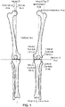
Figure 1 is a schematic view of a representative skeletal structure of the legs of a standing person. -
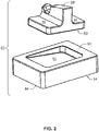
Figure 2 is a perspective exploded view of an impaction cradle for a femoral implant according to an example of the present disclosure. -
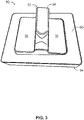
Figure 3 is a top perspective view of an impaction cradle for a femoral implant according to an example of the present disclosure. -
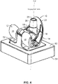
Figure 4 is a perspective view of an impaction cradle with a femoral implant resting thereon according to an example of the present disclosure. -
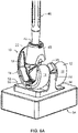
Figure 5A is a side cross-sectional view of the impaction cradle with the femoral implant depicted inFigure 4 . -
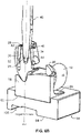
Figure 5B is a partial side cross-sectional view of the impaction cradle with the femoral implant depicted inFigure 5B . -
Figure 6A is a perspective view an impaction cradle with a femoral implant resting thereon, wherein an intramedullary stem and metaphyseal sleeve are impacted onto the femoral implant according to an example of the present disclosure. -
Figure 6B is a cross-sectional perspective view the impaction cradle with the femoral implant and impacted intramedullary stem and metaphyseal sleeve depicted inFigure 6A . -
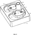
Figure 7 is a perspective view of an impaction cradle for a tibia implant according to an example of the present disclosure. -
Figure 8 is a perspective view of an impaction cradle with a tibia implant resting thereon according to an example of the present disclosure. -
Figure 9A is a side cross-sectional view of the impaction cradle with the tibial implant depicted inFigure 8 . -
Figure 9B is a partial side cross-sectional view of the impaction cradle with the tibial implant depicted inFigure 9A . -
Figure 10A is a perspective view an impaction cradle with a tibia implant resting thereon, wherein an intramedullary stem and metaphyseal sleeve are impacted onto the tibia implant according to an example of the present disclosure. -
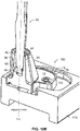
Figure 10B is a cross-sectional perspective view the impaction cradle with the tibia implant and impacted intramedullary stem and metaphyseal sleeve depicted inFigure 10A . - As illustrated in
FIG. 1 , in a standing person, the lateral and medial condyles of the femur rest on a meniscus positioned on the lateral and medial condyles of the tibia. As the hips of most people are often wider than their knees and ankles, their legs are often pivoted slightly inward toward the sagittal plane when standing. For the purposes of this disclosure, the mechanical axis can be defined as an axis drawn from the femoral head to the center of the ankle joint such that the axis passes through the knee slightly media to the tibial spine. The mechanical axis can subtend about 3° to the true vertical axis when the person is standing depending on the height of the person and/or the width of their pelvis. - In a standing person, the articulating surfaces of the lateral and medial condyles of the tibia are positioned in a plane parallel to the true horizontal axis. The tibial anatomical axis can be defined as an axis extending along the length of the intramedullary canal of the tibia. The tibial anatomical axis can be generally parallel to the mechanical axis. The femoral anatomical axis can be defined as the axis extending along the intramedullary canal of the femur. As discussed above, the femoral anatomical axis is typically offset about 5° to 7° from the mechanical axis (about 8° to 10° from the true vertical axis). In addition, an individual's natural joint line can be further angled at a slight varus or valgus angle (about 2° to 3°) from the mechanical axes of the femur and tibia due to the sizing and shape of the individual's condyles and femur and tibia. The overall varus or valgus angle can be defined as the angle from the vertical axis created by the offset of femoral anatomical axis and the varus and valgus variations caused by the sizing and shape of the individual's bone structures.
- As depicted in
FIGS. 4-6B , afemoral component 10, according to an example of the present disclosure, can comprise amedial condyle portion 14 and alateral condyle portion 12. Eachcondyle portion articulating surface 16 and an innerbone contacting surface 18. Thelateral condyle portion 12 can be shaped and sized to approximate the natural lateral condyle of the femur and themedial condyle portion 14 can be shaped and sized to approximate the natural medial condyle of the femur. In particular, themedial condyle portion 12 can be larger in size than thelateral condyle portion 14 to correspond to the relative sizing of natural femoral condyles. The lower most portion of articulatingsurface 16 of thecondyle portions - In an embodiment, the
medial condyle portion 14 and thelateral condyle portion 12 can be connected at one end by thefemoral cam 20 and at the opposite end by thepatellofemoral flange 22. In this configuration, agap 24 can be defined between themedial condyle portion 14 and thelateral condyle portion 12. Thegap 24 corresponding to the natural gap between the medial and lateral condyles of the distal femoral component. - As depicted in
FIGS. 5A-13 and6A-B , in an embodiment, thefemoral component 10 comprises anattachment feature 26 positioned on the bone engaging surface in the middle of the femoral component where the twocondyles 16 meet thepatellofemoral flange 22. As depicted inFIG. 5B , theattachment feature 26 can comprise anattachment port 28 defining aninner surface 30 for engaging anattachment end 42 of anintramedullary stem 40. In an embodiment, theinner surface 30 and theattachment end 42 can have corresponding Morse tapers such that theinner surface 30 frictionally engages theattachment end 42 as theintramedullary stem 40 is impacted into theattachment port 28 along an impaction axis a-a. As depicted inFIG 5A , the impaction axis a-a can be angled offset from a perpendicular angle to the support plane. In at least one example, the impaction axis a-a can be oriented at an angle perpendicular to the support plane. As depicted inFIG. 6B , in an embodiment, theattachment end 42 of theintramedullary stem 40 can comprise a notchedportion 44. In this configuration, theattachment feature 26 can comprise adetent feature 32 positioned to engage the notchedportion 44 to lock theintramedullary stem 40 to thefemoral implant 10. Thedetent feature 32 can be positioned at the bottom of theattachment port 28 to engage the notchedportion 44 when theintramedullary stem 40 is fully impacted into theattachment port 28 of thefemoral implant 10. - When the femoral component rests on the condyle surfaces 16 which are perpendicular to the mechanical axis of the bone, the
attachment feature 26 andattachment port 28 can be angled such that the impaction axis a-a is angled relative to the articulating surface. The angle of the impaction axis a-a can simulate the natural subtend of the femoral anatomical axis from the mechanical axis (about 5° to about 7° and, in certain embodiments, about 6°). In an embodiment, a plurality offemoral components 10 can be provided to a medical practitioner, wherein eachfemoral component 10 can have anattachment port 28 oriented at a different angle to the articulating plane. In this configuration, the medical practitioner can select the appropriatefemoral component 10 to corresponding to the particular subtend of the femoral anatomical axis of the particular patient. - As depicted in
FIGS. 6A-B , in an embodiment, thefemoral implant component 10 can include a sleeve orcone 46 positioned over anouter surface 34 of theattachment feature 26. Thesleeve 46 can comprise a porous material, such as titanium, tantalum, or alloys thereof, for facilitating bone ingrowth and fixation of thefemoral implant component 10. - As depicted in
FIGS. 2-6B , animpaction cradle 50, according to an example of the present disclosure, can comprise acradle element 52 and abase portion 54. Thecradle element 52 can be configured to receive and support thefemoral implant 10. Thebase portion 54 can rest on a planar support surface (e.g. table top) to support thecradle element 52 andfemoral implant 10 thereon. Thecradle element 52 and/or thebase portion 54 can orient afemoral implant 10 resting on thecradle element 52 such that impaction axis a-a defined by theattachment port 28 is oriented vertically. In an embodiment, thefemoral implant 10 can be oriented such that the impaction axis a-a is within a vertical plane bisecting thefemoral implant 10 between themedial condyle portion 14 and thelateral condyle portion 12. In this configuration, thefemoral implant 10 can be angled transverse to the vertical axis and oriented slightly forward or backwards but within the vertical plane. - As depicted in
FIGS. 2-6B , in an embodiment, thecradle element 52 can include at least onesupport surface 56 shaped to interface with a corresponding surface of thefemoral implant 10. Thesupport surface 56 can be shaped to interface with an articulatingsurface 16 of themedial condyle portion 14 or thelateral condyle portion 12 or another surface of thefemoral implant 10. In an embodiment, thecradle element 52 can include at least twosupport surface 56, wherein onesupport surface 56 corresponds to themedial condyle portion 14 and anothersupport surface 56 corresponds to thelateral condyle portion 12. Thesupport surface 56 can define a support plane parallel to the articulating plane defined bymedial condyle portion 14 and thelateral condyle portion 12 when thefemoral implant 10 is positioned on thecradle element 52. - As depicted in
FIGS. 2-4 , in an embodiment, thecradle element 52 can comprise a stabilizingpost 58 positioned between twosupport surfaces 56 corresponding to themedial condyle portion 14 and thelateral condyle portion 12. The stabilizingpost 58 can extend above the support surfaces 56 such that the stabilizingpost 58 can be received within thegap 24 between themedial condyle portion 14 and thelateral condyle portion 12. The stabilizingpost 58 can engage themedial condyle portion 14 and thelateral condyle portion 12 to maintain thefemoral implant 10 on thecradle element 52. - As illustrated in
FIGS. 2-6B , in an embodiment, thebase portion 54 can comprise aplanar body 60 defining a base plane. Thebase portion 54 can orient thecradle element 52 such that the support plane defined by the support surfaces 56 are oriented at an angle to the base plane corresponding to the varus-valgus angle. In an embodiment, the varus-valgus angle of the support plane to the base plane is about 8° to 10° to correspond to the natural subtend of the femoral anatomical axis to the mechanical axis. In this configuration, afemoral implant 10 positioned on thecradle element 52 oriented such that the impaction axis a-a is parallel to a vertical axis or within a vertical plane bisecting thefemoral implant 10 between themedial condyle portion 14 and thelateral condyle portion 12. The generally vertical orientation of the impaction axis a-a can reduce the difficulty of accurately impacting anintramedullary stem 40 into theattachment feature 26. - As depicted in
FIGS. 1 and5A-B , in an embodiment, theplanar body 60 of thebase portion 54 can comprise an angledupper surface 62 for receiving thecradle element 52. The angledupper surface 62 can be angled at the varus-valgus angle to orient the support plane of thecradle element 52 transverse to the base plane at the varus-valgus angle. In an embodiment, theplanar body 60 can comprise a planerlower surface 64 for position thebase portion 54 on a planar support surface (e.g. a table or work bench). The planerlower surface 64 can be parallel to the base plane such that resting the planarlower surface 64 on a planar surface orients the support surface of thecradle element 52 at an angle to the base plane and planar support surface corresponding to the varus-valgus angle. The orientation of the support surfaces at the varus-valgus angle orients afemoral implant 10 received on the support surfaces such that the impaction axis a-a is oriented vertically or nearly vertical to allow for easier and more accurate impactions of the intramedullary stem. - As depicted in
FIGS. 8-10B , atibial implant 70, according to an example of the present disclosure, can comprise amedial condyle portion 72 and alateral condyle portion 74. Eachcondyle portion surface 76 and an innerbone contacting surface 78. Thelateral condyle portion 74 can be shaped and sized to approximate the natural lateral condyle of the tibia and themedial condyle portion 72 can be shaped and sized to approximate the natural medial condyle of the tibia. In particular, thelateral condyle portion 74 can have a larger size to provide a larger articulatingsurface 76 for the larger femoral lateral condyle. The articulating surfaces 76 of themedial condyle portion 72 and thelateral condyle portion 74 can define an articulating plane corresponding to the natural horizontal plane defined by the tibial condyles of a standing person. - As depicted in
FIGS. 9A-B and10A-B , in an embodiment, thetibial implant 70 can comprise anattachment feature 86 positioned on thebone contacting surface 78. As depicted inFIG. 9B , theattachment feature 86 can comprise anattachment port 88 defining aninner surface 90 for engaging anattachment end 42 of anintramedullary stem 40. In an embodiment, theinner surface 90 and theattachment end 42 can have corresponding Morse tapers such that theinner surface 90 frictionally engages theattachment end 42 as theintramedullary stem 40 is impacted into theattachment port 88 along an impaction axis b-b. As depicted inFIG. 9B , in an embodiment, theattachment feature 86 can comprise adetent feature 92 positioned to engage the notchedportion 44 to lock theintramedullary stem 40 to thetibial implant 70. Thedetent feature 92 can be positioned at the bottom of theattachment port 88 to engage the notchedportion 44 when theintramedullary stem 40 is fully impacted into theattachment port 88 of thetibial implant 70. - As the tibial component may have a posterior slope built in, the
attachment feature 86 andattachment port 88 can be angled such that the impaction axis b-b is angled relative to the articulating surface. The angle of the impaction axis b-b can simulate the natural posterior slope of the tibia (about 3°). In an embodiment, a plurality oftibial components 70 can be provided to a medical practitioner, wherein eachtibial components 70 can have anattachment port 88 oriented at a different angle to the articulating plane. - As depicted in
FIGS. 1OA-10B , in an embodiment, thetibial implant component 70 can include a sleeve orcone 46 positioned over anouter surface 34 of theattachment feature 86. Thesleeve 46 can comprise a porous material, such as titanium, tantalum, or alloys thereof, for facilitating bone ingrowth and fixation of thetibial implant component 70. - As depicted in
FIGS. 7-10B , in an embodiment, thebase portion 104 can include at least onesupport surface 106 shaped to interface with a corresponding surface of thetibial implant 70. Thesupport surface 106 can be shaped to interface with an articulatingsurface 76 of themedial condyle portion 72 or thelateral condyle portion 74 or another surface of thetibial implant 70. Thesupport surface 106 can be angled (about 3°) to orient the articulating plane of thetibial implant 70 such that the impaction axis b-b corresponds to the natural posterior slope of the tibia In an embodiment, thesupport surface 106 can include at least twosupport surfaces 106, wherein onesupport surface 106 corresponds to themedial condyle portion 72 and anothersupport surface 106 corresponds to thelateral condyle portion 74. Thesupport surface 106 can define a support plane parallel to the articulating plane defined bymedial condyle portion 72 and thelateral condyle portion 74 when thetibial implant 70 is positioned on thebase portion 104. - As illustrated in
FIGS. 7-10B , in an embodiment, thebase portion 104 can comprise aplanar body 110 defining a base plane. Thebase portion 104 can orient atibial implant 70 positioned on thebase portion 104 such that the support plane defined by the support surfaces 106 is oriented transverse to the base plane at the posterior slope angle. In an embodiment, the posterior slope of the support plane to the base plane is about 3° to correspond to the natural tibia. In this configuration, atibial implant 70 positioned on thebase portion 104 can be oriented such that the impaction axis b-b is parallel to a vertical axis or within a vertical plane bisecting thetibial implant 70 between themedial condyle portion 72 and thelateral condyle portion 74. The generally vertical orientation of the impaction axis b-b can reduce the difficulty of accurately impacting anintramedullary stem 40 into theattachment feature 86. - As illustrated in
FIGS. 7-10B , in an embodiment, thebase portion 104 can comprise aplanar body 110 defining a base plane. Thebase portion 104 can orient atibial implant 70 positioned on thebase portion 104 such that the support plane defined by the support surfaces 106 is oriented transverse to the base plane at the varus-valgus angle. In an embodiment, the varus-valgus angle of the support plane to the base plane is about 3° to correspond to the natural subtend of the tibial anatomical axis to the vertical axis. In this configuration, atibial implant 70 positioned on thebase portion 104 can be oriented such that the impaction axis b-b is parallel to a vertical axis or within a vertical plane bisecting thetibial implant 70 between themedial condyle portion 72 and thelateral condyle portion 74. The generally vertical orientation of the impaction axis b-b can reduce the difficulty of accurately impacting anintramedullary stem 40 into theattachment feature 86. - In an example, the
base portion 54 can comprise both an angledupper surface 62 corresponding to afemoral implant 10 and an angledupper surface 106 corresponding atibial implant 70. As illustrated inFIG. 6B , the femoralangled surface 62 can be positioned on a first side of thebase portion 54 and the tibialangled surface 106 can be positioned on a second side opposite to the first side. In this configuration, thebase portion 54 can be reversibly positioned on the planar support surface to support either thefemoral implant 10 or thetibial implant 10 depending on whether the first or section side is oriented upwards on the planar support surface. The femoralangled surface 62 and the tibialangled surface 106 can be angled to facilitate the reversal of thebase portion 54. This arrangement permits asingle base portion 54 to be selectively used for either thefemoral implant 10 or thetibial implant 10. - The above detailed description includes references to the accompanying drawings, which form a part of the detailed description. The drawings show, by way of illustration, specific embodiments in which the present subject matter can be practiced. These embodiments are also referred to herein as "examples." Such examples can include elements in addition to those shown or described. However, the present inventors also contemplate examples in which only those elements shown or described are provided. Moreover, the present inventors also contemplate examples using any combination or permutation of those elements shown or described (or one or more aspects thereof), either with respect to a particular example (or one or more aspects thereof), or with respect to other examples (or one or more aspects thereof) shown or described herein.
- In this document, the terms "a" or "an" are used, as is common in patent documents, to include one or more than one, independent of any other instances or usages of "at least one" or "one or more." In this document, the term "or" is used to refer to a nonexclusive or, such that "A or B" includes "A but not B," "B but not A," and "A and B," unless otherwise indicated. In this document, the terms "including" and "in which" are used as the plain-English equivalents of the respective terms "comprising" and "wherein." Also, in the following claims, the terms "including" and "comprising" are open-ended, that is, a system, device, article, composition, formulation, or process that includes elements in addition to those listed after such a term in a claim are still deemed to fall within the scope of that claim. Moreover, in the following claims, the terms "first," "second," and "third," etc. are used merely as labels, and are not intended to impose numerical requirements on their objects.
- The above description is intended to be illustrative, and not restrictive. For example, the above-described examples (or one or more aspects thereof) may be used in combination with each other. Other embodiments can be used, such as by one of ordinary skill in the art upon reviewing the above description. The Abstract is provided to comply with 37 C.F.R. §1.72(b), to allow the reader to quickly ascertain the nature of the technical disclosure. It is submitted with the understanding that it will not be used to interpret or limit the scope or meaning of the claims. Also, in the above Detailed Description, various features may be grouped together to streamline the disclosure. This should not be interpreted as intending that an unclaimed disclosed feature is essential to any claim. Rather, inventive subject matter may lie in less than all features of a particular disclosed embodiment.
Claims (21)
- An impaction cradle (50) for supporting a femoral implant (10) during impaction of an intramedullary stem or metaphyseal sleeve onto an attachment feature of the femoral implant along an impaction axis (a-a), comprising:a cradle element (52) having at least one support surface (56) for receiving the femoral implant, the support surface defining a support plane; anda base portion (54) having a planar body (60) defining a base plane;wherein the cradle element is positioned on the base portion such that the cradle element is tilted to orient the support plane transverse to the base plane.
- The impaction cradle (50) of claim 1, wherein the support plane is transverse to the base plane at a transverse angle corresponding to a varus-valgus angle of the femoral implant;
wherein the transverse angle is between about 4 to about 10 degrees. - The impaction cradle (50) of claim 1 or claim 2, wherein pivoting the cradle element (52) orients the femoral implant (10) resting on the support surface (56) such that the impaction axis (a-a) of the femoral implant is perpendicular to the base plane.
- The impaction cradle (50) of any of claims 1-3, wherein the planar body (60) of the base portion (54) further comprises:an angled surface (62) for receiving the cradle element (52);wherein the angled surface is oriented transverse to the base plane at the varus-valgus angle such that the support plane of the cradle element is oriented at the varus-valgus angle.
- The impaction cradle (50) of claim 4, wherein the planar body (60) of the base portion (54) further comprises:a planar base surface opposite the angled surface (62);wherein the base surface is parallel to the base plane.
- The impaction cradle (50) of any of claims 1-5, wherein the cradle element (52) further comprises:
at least two support surfaces (56), wherein each support surface is positioned to engage an articulating surface of one condyle portion of the femoral implant. - The impaction cradle (50) of claim 6, wherein the cradle element further comprises:a stabilizing post (58) extending between the two support surfaces (56);wherein the stabilizing post is receivable between the condyle portions of the femoral implant to maintain the femoral implant on the cradle element.
- A femoral implant system, comprising:the impaction cradle of claim 1 wherein the cradle is tilted to orient the femoral implant such that the impaction axis is generally vertical;a femoral implant (10) having an attachment feature (26); andan intramedullary stem (40) configured to be impacted into the attachment feature along an impaction axis (a-a)r
- The femoral implant system of claim 8, the femoral implant (10) further comprising:a medial femoral condyle portion (14) comprising a medial articulating surface (16); anda lateral femoral condyle portion (12) comprising a lateral articulating surface (16);wherein the medial articulating surface and the lateral articulating surface cooperate to define an articulating plane.
- The femoral implant system of claim 9, wherein the support plane is transverse to the base plane at a transverse angle corresponding to a varus-valgus angle of the femoral implant (10);
wherein the transverse angle is between about 4 to about 10 degrees. - The femoral implant system of claim 9 or claim 10, wherein the articulating plane is parallel to the support plane when the femoral implant (10) is received on the cradle element (52).
- The femoral implant system of any one of claims 8-11, wherein the planar body (60) of the base portion (54) further comprises:an angled surface (62);a planar base surface opposite the angled surface; andwherein the base surface is parallel to the base plane.
- An impaction cradle (50) for supporting a tibial implant (70) during impaction of an intramedullary stem (40) into an attachment port (88) of the tibial implant along an impaction axis (b-b), comprising:
a base portion (104) having a planar body (110) defining a base plane, the planar body further comprising an angled surface (106) oriented transverse to the base plane. - The impaction cradle (50) of claim 13, wherein the angled surface (106) is transverse to the base plane at a transverse angle corresponding to a posterior slope of the tibial implant (70);
wherein the transverse angle is about 3 degrees. - The impaction cradle (50) of claim 13 or claim 14, wherein the planar body (110) of the base portion (104) further comprises:a base surface opposite the angled surface (106);wherein the base surface is parallel to the base plane.
- A tibial implant system, comprising:the impaction cradle of claim 13;a tibial implant (70) having an attachment port (88); andan intramedullary stem (40) configured to be impacted into the attachment port along an impaction axis (b-b).
- The tibial implant system of claim 16, wherein the tibial implant (70) further comprises:a medial tibial condyle portion (72) comprising a medial articulating surface (76); anda lateral tibial condyle portion (74) comprising a lateral articulating surface (76);wherein the medial articulating surface and the lateral articulating surface cooperate to define an articulating plane.
- The tibial implant system of claim 17, wherein the articulating plane is parallel to the angled surface (106) when the tibial implant (70) is received on the impaction cradle (50).
- A knee implant system, comprising:the femoral implant system of claim 8; andthe tibial implant system of claim 16;wherein the base portion of the impaction cradle (50) includes a femoral angled surface (62) for receiving the cradle element (52) and a tibial angled surface (106) for receiving the tibial implant (70);wherein the femoral angled surface is oriented transverse to the base plane at a transverse angle corresponding to a varus-valgus angle of the femoral implant; andwherein the tibial angled surface is oriented transverse to the base plane to orient the tibial implant such that the impaction axis is generally vertical.
- The knee implant system of claim 19, wherein pivoting the cradle element (52) orients the femoral implant (10) resting on the support surface such that the impaction axis (a-a) of the femoral implant is perpendicular to the base plane.
- The knee implant system of claim 19 or 20, wherein the cradle element (52) further comprises:
at least two support surfaces (56), wherein each support surface is positioned to engage an articulating surface (16) of one condyle portion (12, 14) of the femoral implant (10).
Applications Claiming Priority (2)
| Application Number | Priority Date | Filing Date | Title |
|---|---|---|---|
| US201762570889P | 2017-10-11 | 2017-10-11 | |
| PCT/US2018/055218 WO2019075066A1 (en) | 2017-10-11 | 2018-10-10 | Impaction cradle |
Publications (2)
| Publication Number | Publication Date |
|---|---|
| EP3694446A1 EP3694446A1 (en) | 2020-08-19 |
| EP3694446B1 true EP3694446B1 (en) | 2022-12-21 |
Family
ID=64051733
Family Applications (1)
| Application Number | Title | Priority Date | Filing Date |
|---|---|---|---|
| EP18796230.3A Active EP3694446B1 (en) | 2017-10-11 | 2018-10-10 | Impaction cradle |
Country Status (3)
| Country | Link |
|---|---|
| US (2) | US11351041B2 (en) |
| EP (1) | EP3694446B1 (en) |
| WO (1) | WO2019075066A1 (en) |
Families Citing this family (4)
| Publication number | Priority date | Publication date | Assignee | Title |
|---|---|---|---|---|
| US10987225B2 (en) | 2017-08-04 | 2021-04-27 | Zimmer, Inc. | Systems and methods for attaching sleeve or cone in prosthetic implant having a stem |
| WO2019075066A1 (en) | 2017-10-11 | 2019-04-18 | Zimmer, Inc. | Impaction cradle |
| JP7125480B2 (en) | 2017-10-13 | 2022-08-24 | ジンマー,インコーポレイティド | Knee arthroplasty method and instrument |
| CN117653422A (en) * | 2023-11-27 | 2024-03-08 | 北京市春立正达医疗器械股份有限公司 | A porous tantalum modular cementless unicondylar prosthesis |
Family Cites Families (43)
| Publication number | Priority date | Publication date | Assignee | Title |
|---|---|---|---|---|
| US5282861A (en) | 1992-03-11 | 1994-02-01 | Ultramet | Open cell tantalum structures for cancellous bone implants and cell and tissue receptors |
| CA2160198C (en) | 1994-10-27 | 2003-12-30 | Michael J. Pappas | Prosthesis fixturing device |
| US6171342B1 (en) | 1996-07-23 | 2001-01-09 | Depuy Orthopaedics, Inc. | Medical fastening system |
| US7635390B1 (en) * | 2000-01-14 | 2009-12-22 | Marctec, Llc | Joint replacement component having a modular articulating surface |
| US20040162619A1 (en) | 2001-08-27 | 2004-08-19 | Zimmer Technology, Inc. | Tibial augments for use with knee joint prostheses, method of implanting the tibial augment, and associated tools |
| US20030065397A1 (en) | 2001-08-27 | 2003-04-03 | Hanssen Arlen D. | Prosthetic implant support structure |
| ATE337760T1 (en) * | 2001-12-21 | 2006-09-15 | Smith & Nephew Inc | ROTATING JOINT SYSTEM |
| CA2646389A1 (en) * | 2002-02-20 | 2003-08-28 | Donald M. Smucker | Knee arthroplasty prosthesis and method |
| US6902583B2 (en) | 2002-04-25 | 2005-06-07 | Medicinelodge, Inc. | Tripartite attachment mechanism and method for a modular prosthesis |
| US6911100B1 (en) | 2002-08-30 | 2005-06-28 | Biomet, Inc. | Method for controlling residual stress in prosthetics |
| US7291174B2 (en) | 2002-09-09 | 2007-11-06 | Depuy Products, Inc. | Prosthetic tibial component with modular sleeve |
| US7799085B2 (en) | 2003-11-18 | 2010-09-21 | Depuy Products, Inc. | Modular implant system with fully porous coated sleeve |
| US7338497B2 (en) * | 2003-12-05 | 2008-03-04 | Mis-Tka Group, Llc | Femoral impactor-extractor |
| WO2007114841A1 (en) | 2006-04-04 | 2007-10-11 | Smith & Nephew, Inc. | Trial coupler systems and methods |
| US8187280B2 (en) | 2007-10-10 | 2012-05-29 | Biomet Manufacturing Corp. | Knee joint prosthesis system and method for implantation |
| US8562616B2 (en) * | 2007-10-10 | 2013-10-22 | Biomet Manufacturing, Llc | Knee joint prosthesis system and method for implantation |
| US8632600B2 (en) * | 2007-09-25 | 2014-01-21 | Depuy (Ireland) | Prosthesis with modular extensions |
| US8740984B2 (en) * | 2009-10-06 | 2014-06-03 | Microport Orthopedics Holdings Inc. | Tibial implant base |
| US9039710B2 (en) | 2010-12-07 | 2015-05-26 | Zimmer, Inc. | Prosthetic inserter |
| US8778030B2 (en) | 2011-03-24 | 2014-07-15 | Christopher G. Sidebotham | Load bearing implants |
| US8979847B2 (en) | 2011-06-06 | 2015-03-17 | Biomet Manufacturing, Llc | Method and apparatus for implanting a knee prosthesis |
| US8968412B2 (en) | 2011-06-30 | 2015-03-03 | Depuy (Ireland) | Trialing system for a knee prosthesis and method of use |
| US8556900B2 (en) | 2011-12-01 | 2013-10-15 | Zimmer, Inc. | Surgical instrument for impacting and extracting a cutting instrument |
| AU2012362279A1 (en) | 2011-12-30 | 2014-07-24 | Howmedica Osteonics Corp. | Systems for preparing bone voids to receive a prosthesis |
| US8721733B2 (en) | 2012-05-14 | 2014-05-13 | Depuy (Ireland) | Prosthesis kit with finned sleeve |
| US9113915B2 (en) | 2012-05-30 | 2015-08-25 | Depuy (Ireland) | Method of surgically preparing a patient's tibia |
| US8998996B2 (en) | 2012-09-20 | 2015-04-07 | Depuy (Ireland) | Knee prosthesis system with standard and distal offset joint line |
| WO2014063084A1 (en) * | 2012-10-18 | 2014-04-24 | Smith & Nephew, Inc. | Alignment devices and methods |
| US9937063B2 (en) | 2013-02-14 | 2018-04-10 | Zimmer, Inc. | Trialing for prosthetic component |
| US9220511B2 (en) | 2013-02-28 | 2015-12-29 | Depuy (Ireland) | Femoral orthopaedic surgical instrument including a measurement device and method of use of same |
| US9107757B2 (en) | 2013-03-13 | 2015-08-18 | Depuy (Ireland) | Tibial trial instruments for setting offset |
| US9737408B2 (en) * | 2013-03-15 | 2017-08-22 | Depuy Ireland Unlimited Company | Tibial impaction guide surgical instrument and method of using same |
| US9113918B2 (en) | 2013-03-15 | 2015-08-25 | Depuy (Ireland) | Femoral surgical instrument and method of using same |
| US10596009B2 (en) | 2013-03-15 | 2020-03-24 | Smith & Nephew, Inc. | Knee augment |
| US9603649B2 (en) | 2013-03-15 | 2017-03-28 | Depuy Ireland Unlimited Company | Instruments for use in disassembling implants |
| US20150216667A1 (en) | 2014-02-04 | 2015-08-06 | Zimmer, Inc. | Tapered adapter |
| AU2015229377B2 (en) | 2014-03-12 | 2019-09-19 | Advita Ortho, LLC. | Prosthesis component with offset adjustability |
| US20180125662A1 (en) | 2015-05-13 | 2018-05-10 | Smith & Nephew, Inc. | Anatomically relieved augments |
| US9999428B2 (en) | 2015-06-30 | 2018-06-19 | DePuy Synthes Products, Inc. | Orthopaedic surgical instrument system and method for surgically preparing a patients bone |
| US10182830B2 (en) | 2016-04-05 | 2019-01-22 | Arthrology Consulting, Llc | Modular total knee arthroplasty system and method |
| US10987225B2 (en) | 2017-08-04 | 2021-04-27 | Zimmer, Inc. | Systems and methods for attaching sleeve or cone in prosthetic implant having a stem |
| WO2019075066A1 (en) | 2017-10-11 | 2019-04-18 | Zimmer, Inc. | Impaction cradle |
| JP7125480B2 (en) | 2017-10-13 | 2022-08-24 | ジンマー,インコーポレイティド | Knee arthroplasty method and instrument |
-
2018
- 2018-10-10 WO PCT/US2018/055218 patent/WO2019075066A1/en not_active Ceased
- 2018-10-10 EP EP18796230.3A patent/EP3694446B1/en active Active
- 2018-10-10 US US16/652,896 patent/US11351041B2/en active Active
-
2022
- 2022-04-29 US US17/733,768 patent/US20220249251A1/en active Pending
Also Published As
| Publication number | Publication date |
|---|---|
| US20220249251A1 (en) | 2022-08-11 |
| US11351041B2 (en) | 2022-06-07 |
| US20200289290A1 (en) | 2020-09-17 |
| WO2019075066A1 (en) | 2019-04-18 |
| EP3694446A1 (en) | 2020-08-19 |
Similar Documents
| Publication | Publication Date | Title |
|---|---|---|
| US20220249251A1 (en) | Impaction cradle | |
| Townley | The anatomic total knee resurfacing arthroplasty. | |
| JP4774485B2 (en) | Shoulder prosthesis using a fracture stem of the humerus | |
| AU2012217694B2 (en) | Modular prosthesis | |
| US8211041B2 (en) | Sensing force during partial and total knee replacement surgery | |
| US10898347B2 (en) | Surgical instrument and method of use | |
| US20010047210A1 (en) | Facile total shoulder arthroplasty apparatus and method | |
| US20130296860A1 (en) | Knee balancing for revision procedures | |
| US20090088862A1 (en) | Stem extension and adaptor for use with a knee orthopaedic implant | |
| US10568742B2 (en) | Tibial insert | |
| US11491018B2 (en) | Tibial prosthesis for tibia with varus resection | |
| AU2003204796A1 (en) | Porous unicondylar knee | |
| EP2953583B1 (en) | Tapered tibial augment | |
| US9393124B2 (en) | Patella implant systems and patella trials for selecting same | |
| US20200121476A1 (en) | Trial neck | |
| US11596519B2 (en) | Hinge knee assembly guide | |
| CN213190328U (en) | Positioner for replacing femoral apex by artificial hip joint | |
| US20200107941A1 (en) | Orientation guide | |
| AU2020201730A1 (en) | Biomechanics specific system for primary total knee replacement (tkr) | |
| Abrassart et al. | Measurements of shoulder prosthesis positioning | |
| Celli | Biomaterial Applications: Shoulder Prosthesis | |
| GB2420715A (en) | Arthroplastic surgical apparatus |
Legal Events
| Date | Code | Title | Description |
|---|---|---|---|
| STAA | Information on the status of an ep patent application or granted ep patent |
Free format text: STATUS: UNKNOWN |
|
| STAA | Information on the status of an ep patent application or granted ep patent |
Free format text: STATUS: THE INTERNATIONAL PUBLICATION HAS BEEN MADE |
|
| PUAI | Public reference made under article 153(3) epc to a published international application that has entered the european phase |
Free format text: ORIGINAL CODE: 0009012 |
|
| STAA | Information on the status of an ep patent application or granted ep patent |
Free format text: STATUS: REQUEST FOR EXAMINATION WAS MADE |
|
| 17P | Request for examination filed |
Effective date: 20200511 |
|
| AK | Designated contracting states |
Kind code of ref document: A1 Designated state(s): AL AT BE BG CH CY CZ DE DK EE ES FI FR GB GR HR HU IE IS IT LI LT LU LV MC MK MT NL NO PL PT RO RS SE SI SK SM TR |
|
| AX | Request for extension of the european patent |
Extension state: BA ME |
|
| DAV | Request for validation of the european patent (deleted) | ||
| DAX | Request for extension of the european patent (deleted) | ||
| STAA | Information on the status of an ep patent application or granted ep patent |
Free format text: STATUS: EXAMINATION IS IN PROGRESS |
|
| 17Q | First examination report despatched |
Effective date: 20210422 |
|
| GRAP | Despatch of communication of intention to grant a patent |
Free format text: ORIGINAL CODE: EPIDOSNIGR1 |
|
| STAA | Information on the status of an ep patent application or granted ep patent |
Free format text: STATUS: GRANT OF PATENT IS INTENDED |
|
| INTG | Intention to grant announced |
Effective date: 20220705 |
|
| RIN1 | Information on inventor provided before grant (corrected) |
Inventor name: VANDIEPENBOS, JEFFERY A. Inventor name: SZALKOWSKI, AMANDA Inventor name: YOKO, TIM |
|
| GRAS | Grant fee paid |
Free format text: ORIGINAL CODE: EPIDOSNIGR3 |
|
| GRAA | (expected) grant |
Free format text: ORIGINAL CODE: 0009210 |
|
| STAA | Information on the status of an ep patent application or granted ep patent |
Free format text: STATUS: THE PATENT HAS BEEN GRANTED |
|
| AK | Designated contracting states |
Kind code of ref document: B1 Designated state(s): AL AT BE BG CH CY CZ DE DK EE ES FI FR GB GR HR HU IE IS IT LI LT LU LV MC MK MT NL NO PL PT RO RS SE SI SK SM TR |
|
| REG | Reference to a national code |
Ref country code: GB Ref legal event code: FG4D |
|
| REG | Reference to a national code |
Ref country code: CH Ref legal event code: EP |
|
| REG | Reference to a national code |
Ref country code: DE Ref legal event code: R096 Ref document number: 602018044556 Country of ref document: DE |
|
| REG | Reference to a national code |
Ref country code: AT Ref legal event code: REF Ref document number: 1538606 Country of ref document: AT Kind code of ref document: T Effective date: 20230115 |
|
| REG | Reference to a national code |
Ref country code: IE Ref legal event code: FG4D |
|
| REG | Reference to a national code |
Ref country code: LT Ref legal event code: MG9D |
|
| REG | Reference to a national code |
Ref country code: NL Ref legal event code: MP Effective date: 20221221 |
|
| PG25 | Lapsed in a contracting state [announced via postgrant information from national office to epo] |
Ref country code: SE Free format text: LAPSE BECAUSE OF FAILURE TO SUBMIT A TRANSLATION OF THE DESCRIPTION OR TO PAY THE FEE WITHIN THE PRESCRIBED TIME-LIMIT Effective date: 20221221 Ref country code: NO Free format text: LAPSE BECAUSE OF FAILURE TO SUBMIT A TRANSLATION OF THE DESCRIPTION OR TO PAY THE FEE WITHIN THE PRESCRIBED TIME-LIMIT Effective date: 20230321 Ref country code: LT Free format text: LAPSE BECAUSE OF FAILURE TO SUBMIT A TRANSLATION OF THE DESCRIPTION OR TO PAY THE FEE WITHIN THE PRESCRIBED TIME-LIMIT Effective date: 20221221 Ref country code: FI Free format text: LAPSE BECAUSE OF FAILURE TO SUBMIT A TRANSLATION OF THE DESCRIPTION OR TO PAY THE FEE WITHIN THE PRESCRIBED TIME-LIMIT Effective date: 20221221 |
|
| REG | Reference to a national code |
Ref country code: AT Ref legal event code: MK05 Ref document number: 1538606 Country of ref document: AT Kind code of ref document: T Effective date: 20221221 |
|
| PG25 | Lapsed in a contracting state [announced via postgrant information from national office to epo] |
Ref country code: RS Free format text: LAPSE BECAUSE OF FAILURE TO SUBMIT A TRANSLATION OF THE DESCRIPTION OR TO PAY THE FEE WITHIN THE PRESCRIBED TIME-LIMIT Effective date: 20221221 Ref country code: LV Free format text: LAPSE BECAUSE OF FAILURE TO SUBMIT A TRANSLATION OF THE DESCRIPTION OR TO PAY THE FEE WITHIN THE PRESCRIBED TIME-LIMIT Effective date: 20221221 Ref country code: HR Free format text: LAPSE BECAUSE OF FAILURE TO SUBMIT A TRANSLATION OF THE DESCRIPTION OR TO PAY THE FEE WITHIN THE PRESCRIBED TIME-LIMIT Effective date: 20221221 Ref country code: GR Free format text: LAPSE BECAUSE OF FAILURE TO SUBMIT A TRANSLATION OF THE DESCRIPTION OR TO PAY THE FEE WITHIN THE PRESCRIBED TIME-LIMIT Effective date: 20230322 |
|
| PG25 | Lapsed in a contracting state [announced via postgrant information from national office to epo] |
Ref country code: NL Free format text: LAPSE BECAUSE OF FAILURE TO SUBMIT A TRANSLATION OF THE DESCRIPTION OR TO PAY THE FEE WITHIN THE PRESCRIBED TIME-LIMIT Effective date: 20221221 |
|
| P01 | Opt-out of the competence of the unified patent court (upc) registered |
Effective date: 20230525 |
|
| PG25 | Lapsed in a contracting state [announced via postgrant information from national office to epo] |
Ref country code: SM Free format text: LAPSE BECAUSE OF FAILURE TO SUBMIT A TRANSLATION OF THE DESCRIPTION OR TO PAY THE FEE WITHIN THE PRESCRIBED TIME-LIMIT Effective date: 20221221 Ref country code: RO Free format text: LAPSE BECAUSE OF FAILURE TO SUBMIT A TRANSLATION OF THE DESCRIPTION OR TO PAY THE FEE WITHIN THE PRESCRIBED TIME-LIMIT Effective date: 20221221 Ref country code: PT Free format text: LAPSE BECAUSE OF FAILURE TO SUBMIT A TRANSLATION OF THE DESCRIPTION OR TO PAY THE FEE WITHIN THE PRESCRIBED TIME-LIMIT Effective date: 20230421 Ref country code: ES Free format text: LAPSE BECAUSE OF FAILURE TO SUBMIT A TRANSLATION OF THE DESCRIPTION OR TO PAY THE FEE WITHIN THE PRESCRIBED TIME-LIMIT Effective date: 20221221 Ref country code: EE Free format text: LAPSE BECAUSE OF FAILURE TO SUBMIT A TRANSLATION OF THE DESCRIPTION OR TO PAY THE FEE WITHIN THE PRESCRIBED TIME-LIMIT Effective date: 20221221 Ref country code: CZ Free format text: LAPSE BECAUSE OF FAILURE TO SUBMIT A TRANSLATION OF THE DESCRIPTION OR TO PAY THE FEE WITHIN THE PRESCRIBED TIME-LIMIT Effective date: 20221221 Ref country code: AT Free format text: LAPSE BECAUSE OF FAILURE TO SUBMIT A TRANSLATION OF THE DESCRIPTION OR TO PAY THE FEE WITHIN THE PRESCRIBED TIME-LIMIT Effective date: 20221221 |
|
| PG25 | Lapsed in a contracting state [announced via postgrant information from national office to epo] |
Ref country code: SK Free format text: LAPSE BECAUSE OF FAILURE TO SUBMIT A TRANSLATION OF THE DESCRIPTION OR TO PAY THE FEE WITHIN THE PRESCRIBED TIME-LIMIT Effective date: 20221221 Ref country code: PL Free format text: LAPSE BECAUSE OF FAILURE TO SUBMIT A TRANSLATION OF THE DESCRIPTION OR TO PAY THE FEE WITHIN THE PRESCRIBED TIME-LIMIT Effective date: 20221221 Ref country code: IS Free format text: LAPSE BECAUSE OF FAILURE TO SUBMIT A TRANSLATION OF THE DESCRIPTION OR TO PAY THE FEE WITHIN THE PRESCRIBED TIME-LIMIT Effective date: 20230421 Ref country code: AL Free format text: LAPSE BECAUSE OF FAILURE TO SUBMIT A TRANSLATION OF THE DESCRIPTION OR TO PAY THE FEE WITHIN THE PRESCRIBED TIME-LIMIT Effective date: 20221221 |
|
| REG | Reference to a national code |
Ref country code: DE Ref legal event code: R097 Ref document number: 602018044556 Country of ref document: DE |
|
| PLBE | No opposition filed within time limit |
Free format text: ORIGINAL CODE: 0009261 |
|
| STAA | Information on the status of an ep patent application or granted ep patent |
Free format text: STATUS: NO OPPOSITION FILED WITHIN TIME LIMIT |
|
| PG25 | Lapsed in a contracting state [announced via postgrant information from national office to epo] |
Ref country code: DK Free format text: LAPSE BECAUSE OF FAILURE TO SUBMIT A TRANSLATION OF THE DESCRIPTION OR TO PAY THE FEE WITHIN THE PRESCRIBED TIME-LIMIT Effective date: 20221221 |
|
| 26N | No opposition filed |
Effective date: 20230922 |
|
| PG25 | Lapsed in a contracting state [announced via postgrant information from national office to epo] |
Ref country code: SI Free format text: LAPSE BECAUSE OF FAILURE TO SUBMIT A TRANSLATION OF THE DESCRIPTION OR TO PAY THE FEE WITHIN THE PRESCRIBED TIME-LIMIT Effective date: 20221221 |
|
| PG25 | Lapsed in a contracting state [announced via postgrant information from national office to epo] |
Ref country code: IT Free format text: LAPSE BECAUSE OF FAILURE TO SUBMIT A TRANSLATION OF THE DESCRIPTION OR TO PAY THE FEE WITHIN THE PRESCRIBED TIME-LIMIT Effective date: 20221221 Ref country code: MC Free format text: LAPSE BECAUSE OF FAILURE TO SUBMIT A TRANSLATION OF THE DESCRIPTION OR TO PAY THE FEE WITHIN THE PRESCRIBED TIME-LIMIT Effective date: 20221221 |
|
| REG | Reference to a national code |
Ref country code: CH Ref legal event code: PL |
|
| REG | Reference to a national code |
Ref country code: BE Ref legal event code: MM Effective date: 20231031 |
|
| PG25 | Lapsed in a contracting state [announced via postgrant information from national office to epo] |
Ref country code: LU Free format text: LAPSE BECAUSE OF NON-PAYMENT OF DUE FEES Effective date: 20231010 |
|
| PG25 | Lapsed in a contracting state [announced via postgrant information from national office to epo] |
Ref country code: LU Free format text: LAPSE BECAUSE OF NON-PAYMENT OF DUE FEES Effective date: 20231010 |
|
| PG25 | Lapsed in a contracting state [announced via postgrant information from national office to epo] |
Ref country code: CH Free format text: LAPSE BECAUSE OF NON-PAYMENT OF DUE FEES Effective date: 20231031 |
|
| PG25 | Lapsed in a contracting state [announced via postgrant information from national office to epo] |
Ref country code: CH Free format text: LAPSE BECAUSE OF NON-PAYMENT OF DUE FEES Effective date: 20231031 |
|
| PG25 | Lapsed in a contracting state [announced via postgrant information from national office to epo] |
Ref country code: BE Free format text: LAPSE BECAUSE OF NON-PAYMENT OF DUE FEES Effective date: 20231031 |
|
| PG25 | Lapsed in a contracting state [announced via postgrant information from national office to epo] |
Ref country code: IE Free format text: LAPSE BECAUSE OF NON-PAYMENT OF DUE FEES Effective date: 20231010 |
|
| PG25 | Lapsed in a contracting state [announced via postgrant information from national office to epo] |
Ref country code: IE Free format text: LAPSE BECAUSE OF NON-PAYMENT OF DUE FEES Effective date: 20231010 |
|
| PG25 | Lapsed in a contracting state [announced via postgrant information from national office to epo] |
Ref country code: BG Free format text: LAPSE BECAUSE OF FAILURE TO SUBMIT A TRANSLATION OF THE DESCRIPTION OR TO PAY THE FEE WITHIN THE PRESCRIBED TIME-LIMIT Effective date: 20221221 |
|
| PG25 | Lapsed in a contracting state [announced via postgrant information from national office to epo] |
Ref country code: BG Free format text: LAPSE BECAUSE OF FAILURE TO SUBMIT A TRANSLATION OF THE DESCRIPTION OR TO PAY THE FEE WITHIN THE PRESCRIBED TIME-LIMIT Effective date: 20221221 |
|
| PG25 | Lapsed in a contracting state [announced via postgrant information from national office to epo] |
Ref country code: CY Free format text: LAPSE BECAUSE OF FAILURE TO SUBMIT A TRANSLATION OF THE DESCRIPTION OR TO PAY THE FEE WITHIN THE PRESCRIBED TIME-LIMIT; INVALID AB INITIO Effective date: 20181010 |
|
| PG25 | Lapsed in a contracting state [announced via postgrant information from national office to epo] |
Ref country code: HU Free format text: LAPSE BECAUSE OF FAILURE TO SUBMIT A TRANSLATION OF THE DESCRIPTION OR TO PAY THE FEE WITHIN THE PRESCRIBED TIME-LIMIT; INVALID AB INITIO Effective date: 20181010 |
|
| PG25 | Lapsed in a contracting state [announced via postgrant information from national office to epo] |
Ref country code: TR Free format text: LAPSE BECAUSE OF FAILURE TO SUBMIT A TRANSLATION OF THE DESCRIPTION OR TO PAY THE FEE WITHIN THE PRESCRIBED TIME-LIMIT Effective date: 20221221 |
|
| PGFP | Annual fee paid to national office [announced via postgrant information from national office to epo] |
Ref country code: DE Payment date: 20251010 Year of fee payment: 8 |
|
| PGFP | Annual fee paid to national office [announced via postgrant information from national office to epo] |
Ref country code: GB Payment date: 20251013 Year of fee payment: 8 |
|
| PGFP | Annual fee paid to national office [announced via postgrant information from national office to epo] |
Ref country code: FR Payment date: 20251014 Year of fee payment: 8 |