EP3694352B1 - Evaporator unit for an inhaler, in particular for an electronic cigarette product - Google Patents
Evaporator unit for an inhaler, in particular for an electronic cigarette product Download PDFInfo
- Publication number
- EP3694352B1 EP3694352B1 EP18786274.3A EP18786274A EP3694352B1 EP 3694352 B1 EP3694352 B1 EP 3694352B1 EP 18786274 A EP18786274 A EP 18786274A EP 3694352 B1 EP3694352 B1 EP 3694352B1
- Authority
- EP
- European Patent Office
- Prior art keywords
- evaporator unit
- unit according
- heating body
- wick structure
- support
- Prior art date
- Legal status (The legal status is an assumption and is not a legal conclusion. Google has not performed a legal analysis and makes no representation as to the accuracy of the status listed.)
- Active
Links
- 239000003571 electronic cigarette Substances 0.000 title claims description 6
- 238000010438 heat treatment Methods 0.000 claims description 107
- 239000007788 liquid Substances 0.000 claims description 69
- 238000001704 evaporation Methods 0.000 claims description 27
- 230000008020 evaporation Effects 0.000 claims description 27
- 239000000919 ceramic Substances 0.000 claims description 21
- 239000000463 material Substances 0.000 claims description 12
- 239000004020 conductor Substances 0.000 claims description 9
- 239000003365 glass fiber Substances 0.000 claims description 9
- 239000002184 metal Substances 0.000 claims description 7
- 239000000835 fiber Substances 0.000 claims description 4
- QTBSBXVTEAMEQO-UHFFFAOYSA-M Acetate Chemical compound CC([O-])=O QTBSBXVTEAMEQO-UHFFFAOYSA-M 0.000 claims description 3
- 229920000742 Cotton Polymers 0.000 claims description 3
- 229910000323 aluminium silicate Inorganic materials 0.000 claims description 3
- 229920002678 cellulose Polymers 0.000 claims description 3
- 239000001913 cellulose Substances 0.000 claims description 3
- HNPSIPDUKPIQMN-UHFFFAOYSA-N dioxosilane;oxo(oxoalumanyloxy)alumane Chemical compound O=[Si]=O.O=[Al]O[Al]=O HNPSIPDUKPIQMN-UHFFFAOYSA-N 0.000 claims description 3
- 239000004744 fabric Substances 0.000 claims description 3
- 239000006262 metallic foam Substances 0.000 claims description 3
- 239000000123 paper Substances 0.000 claims description 3
- 241000217776 Holocentridae Species 0.000 claims description 2
- 239000000443 aerosol Substances 0.000 description 5
- 235000019504 cigarettes Nutrition 0.000 description 5
- 230000015572 biosynthetic process Effects 0.000 description 4
- 238000000034 method Methods 0.000 description 4
- 239000000203 mixture Substances 0.000 description 4
- 239000006200 vaporizer Substances 0.000 description 4
- XUIMIQQOPSSXEZ-UHFFFAOYSA-N Silicon Chemical compound [Si] XUIMIQQOPSSXEZ-UHFFFAOYSA-N 0.000 description 3
- 239000003344 environmental pollutant Substances 0.000 description 3
- 239000011521 glass Substances 0.000 description 3
- 238000004519 manufacturing process Methods 0.000 description 3
- 231100000719 pollutant Toxicity 0.000 description 3
- 238000007789 sealing Methods 0.000 description 3
- 229910052710 silicon Inorganic materials 0.000 description 3
- 239000010703 silicon Substances 0.000 description 3
- PEDCQBHIVMGVHV-UHFFFAOYSA-N Glycerine Chemical compound OCC(O)CO PEDCQBHIVMGVHV-UHFFFAOYSA-N 0.000 description 2
- DNIAPMSPPWPWGF-UHFFFAOYSA-N Propylene glycol Chemical compound CC(O)CO DNIAPMSPPWPWGF-UHFFFAOYSA-N 0.000 description 2
- 238000009835 boiling Methods 0.000 description 2
- 239000002131 composite material Substances 0.000 description 2
- 230000000694 effects Effects 0.000 description 2
- 238000005516 engineering process Methods 0.000 description 2
- 239000003921 oil Substances 0.000 description 2
- 239000004033 plastic Substances 0.000 description 2
- 229920003023 plastic Polymers 0.000 description 2
- 239000011148 porous material Substances 0.000 description 2
- 238000012360 testing method Methods 0.000 description 2
- SNICXCGAKADSCV-JTQLQIEISA-N (-)-Nicotine Chemical compound CN1CCC[C@H]1C1=CC=CN=C1 SNICXCGAKADSCV-JTQLQIEISA-N 0.000 description 1
- 229910001369 Brass Inorganic materials 0.000 description 1
- OKTJSMMVPCPJKN-UHFFFAOYSA-N Carbon Chemical compound [C] OKTJSMMVPCPJKN-UHFFFAOYSA-N 0.000 description 1
- 229920002430 Fibre-reinforced plastic Polymers 0.000 description 1
- HBBGRARXTFLTSG-UHFFFAOYSA-N Lithium ion Chemical compound [Li+] HBBGRARXTFLTSG-UHFFFAOYSA-N 0.000 description 1
- 238000010521 absorption reaction Methods 0.000 description 1
- 239000004480 active ingredient Substances 0.000 description 1
- 230000006399 behavior Effects 0.000 description 1
- 239000010951 brass Substances 0.000 description 1
- 230000008878 coupling Effects 0.000 description 1
- 238000010168 coupling process Methods 0.000 description 1
- 238000005859 coupling reaction Methods 0.000 description 1
- 238000013461 design Methods 0.000 description 1
- 238000005265 energy consumption Methods 0.000 description 1
- 239000011151 fibre-reinforced plastic Substances 0.000 description 1
- 239000000796 flavoring agent Substances 0.000 description 1
- 235000019634 flavors Nutrition 0.000 description 1
- 230000006870 function Effects 0.000 description 1
- 229910052732 germanium Inorganic materials 0.000 description 1
- GNPVGFCGXDBREM-UHFFFAOYSA-N germanium atom Chemical compound [Ge] GNPVGFCGXDBREM-UHFFFAOYSA-N 0.000 description 1
- 235000011187 glycerol Nutrition 0.000 description 1
- 229910002804 graphite Inorganic materials 0.000 description 1
- 239000010439 graphite Substances 0.000 description 1
- 230000017525 heat dissipation Effects 0.000 description 1
- 239000011810 insulating material Substances 0.000 description 1
- 229910001416 lithium ion Inorganic materials 0.000 description 1
- 239000011159 matrix material Substances 0.000 description 1
- 238000012544 monitoring process Methods 0.000 description 1
- 229960002715 nicotine Drugs 0.000 description 1
- SNICXCGAKADSCV-UHFFFAOYSA-N nicotine Natural products CN1CCCC1C1=CC=CN=C1 SNICXCGAKADSCV-UHFFFAOYSA-N 0.000 description 1
- 239000012811 non-conductive material Substances 0.000 description 1
- 238000013021 overheating Methods 0.000 description 1
- 230000000149 penetrating effect Effects 0.000 description 1
- 238000012545 processing Methods 0.000 description 1
- 239000004065 semiconductor Substances 0.000 description 1
- 230000002269 spontaneous effect Effects 0.000 description 1
- 239000010409 thin film Substances 0.000 description 1
- 238000011144 upstream manufacturing Methods 0.000 description 1
- XLYOFNOQVPJJNP-UHFFFAOYSA-N water Substances O XLYOFNOQVPJJNP-UHFFFAOYSA-N 0.000 description 1
Images

Classifications
-
- A—HUMAN NECESSITIES
- A24—TOBACCO; CIGARS; CIGARETTES; SIMULATED SMOKING DEVICES; SMOKERS' REQUISITES
- A24F—SMOKERS' REQUISITES; MATCH BOXES; SIMULATED SMOKING DEVICES
- A24F40/00—Electrically operated smoking devices; Component parts thereof; Manufacture thereof; Maintenance or testing thereof; Charging means specially adapted therefor
- A24F40/40—Constructional details, e.g. connection of cartridges and battery parts
-
- A—HUMAN NECESSITIES
- A61—MEDICAL OR VETERINARY SCIENCE; HYGIENE
- A61M—DEVICES FOR INTRODUCING MEDIA INTO, OR ONTO, THE BODY; DEVICES FOR TRANSDUCING BODY MEDIA OR FOR TAKING MEDIA FROM THE BODY; DEVICES FOR PRODUCING OR ENDING SLEEP OR STUPOR
- A61M15/00—Inhalators
- A61M15/06—Inhaling appliances shaped like cigars, cigarettes or pipes
-
- A—HUMAN NECESSITIES
- A24—TOBACCO; CIGARS; CIGARETTES; SIMULATED SMOKING DEVICES; SMOKERS' REQUISITES
- A24F—SMOKERS' REQUISITES; MATCH BOXES; SIMULATED SMOKING DEVICES
- A24F40/00—Electrically operated smoking devices; Component parts thereof; Manufacture thereof; Maintenance or testing thereof; Charging means specially adapted therefor
- A24F40/40—Constructional details, e.g. connection of cartridges and battery parts
- A24F40/42—Cartridges or containers for inhalable precursors
-
- A—HUMAN NECESSITIES
- A24—TOBACCO; CIGARS; CIGARETTES; SIMULATED SMOKING DEVICES; SMOKERS' REQUISITES
- A24F—SMOKERS' REQUISITES; MATCH BOXES; SIMULATED SMOKING DEVICES
- A24F40/00—Electrically operated smoking devices; Component parts thereof; Manufacture thereof; Maintenance or testing thereof; Charging means specially adapted therefor
- A24F40/40—Constructional details, e.g. connection of cartridges and battery parts
- A24F40/44—Wicks
-
- A—HUMAN NECESSITIES
- A24—TOBACCO; CIGARS; CIGARETTES; SIMULATED SMOKING DEVICES; SMOKERS' REQUISITES
- A24F—SMOKERS' REQUISITES; MATCH BOXES; SIMULATED SMOKING DEVICES
- A24F40/00—Electrically operated smoking devices; Component parts thereof; Manufacture thereof; Maintenance or testing thereof; Charging means specially adapted therefor
- A24F40/40—Constructional details, e.g. connection of cartridges and battery parts
- A24F40/46—Shape or structure of electric heating means
-
- A—HUMAN NECESSITIES
- A24—TOBACCO; CIGARS; CIGARETTES; SIMULATED SMOKING DEVICES; SMOKERS' REQUISITES
- A24F—SMOKERS' REQUISITES; MATCH BOXES; SIMULATED SMOKING DEVICES
- A24F40/00—Electrically operated smoking devices; Component parts thereof; Manufacture thereof; Maintenance or testing thereof; Charging means specially adapted therefor
- A24F40/40—Constructional details, e.g. connection of cartridges and battery parts
- A24F40/48—Fluid transfer means, e.g. pumps
- A24F40/485—Valves; Apertures
-
- A—HUMAN NECESSITIES
- A61—MEDICAL OR VETERINARY SCIENCE; HYGIENE
- A61M—DEVICES FOR INTRODUCING MEDIA INTO, OR ONTO, THE BODY; DEVICES FOR TRANSDUCING BODY MEDIA OR FOR TAKING MEDIA FROM THE BODY; DEVICES FOR PRODUCING OR ENDING SLEEP OR STUPOR
- A61M11/00—Sprayers or atomisers specially adapted for therapeutic purposes
- A61M11/04—Sprayers or atomisers specially adapted for therapeutic purposes operated by the vapour pressure of the liquid to be sprayed or atomised
- A61M11/041—Sprayers or atomisers specially adapted for therapeutic purposes operated by the vapour pressure of the liquid to be sprayed or atomised using heaters
- A61M11/042—Sprayers or atomisers specially adapted for therapeutic purposes operated by the vapour pressure of the liquid to be sprayed or atomised using heaters electrical
-
- A—HUMAN NECESSITIES
- A61—MEDICAL OR VETERINARY SCIENCE; HYGIENE
- A61M—DEVICES FOR INTRODUCING MEDIA INTO, OR ONTO, THE BODY; DEVICES FOR TRANSDUCING BODY MEDIA OR FOR TAKING MEDIA FROM THE BODY; DEVICES FOR PRODUCING OR ENDING SLEEP OR STUPOR
- A61M15/00—Inhalators
- A61M15/02—Inhalators with activated or ionised fluids, e.g. electrohydrodynamic [EHD] or electrostatic devices; Ozone-inhalators with radioactive tagged particles
- A61M15/025—Bubble jet droplet ejection devices
-
- A—HUMAN NECESSITIES
- A24—TOBACCO; CIGARS; CIGARETTES; SIMULATED SMOKING DEVICES; SMOKERS' REQUISITES
- A24F—SMOKERS' REQUISITES; MATCH BOXES; SIMULATED SMOKING DEVICES
- A24F40/00—Electrically operated smoking devices; Component parts thereof; Manufacture thereof; Maintenance or testing thereof; Charging means specially adapted therefor
- A24F40/10—Devices using liquid inhalable precursors
-
- A—HUMAN NECESSITIES
- A24—TOBACCO; CIGARS; CIGARETTES; SIMULATED SMOKING DEVICES; SMOKERS' REQUISITES
- A24F—SMOKERS' REQUISITES; MATCH BOXES; SIMULATED SMOKING DEVICES
- A24F40/00—Electrically operated smoking devices; Component parts thereof; Manufacture thereof; Maintenance or testing thereof; Charging means specially adapted therefor
- A24F40/50—Control or monitoring
- A24F40/51—Arrangement of sensors
-
- A—HUMAN NECESSITIES
- A61—MEDICAL OR VETERINARY SCIENCE; HYGIENE
- A61M—DEVICES FOR INTRODUCING MEDIA INTO, OR ONTO, THE BODY; DEVICES FOR TRANSDUCING BODY MEDIA OR FOR TAKING MEDIA FROM THE BODY; DEVICES FOR PRODUCING OR ENDING SLEEP OR STUPOR
- A61M16/00—Devices for influencing the respiratory system of patients by gas treatment, e.g. mouth-to-mouth respiration; Tracheal tubes
- A61M16/0003—Accessories therefor, e.g. sensors, vibrators, negative pressure
- A61M2016/0015—Accessories therefor, e.g. sensors, vibrators, negative pressure inhalation detectors
- A61M2016/0018—Accessories therefor, e.g. sensors, vibrators, negative pressure inhalation detectors electrical
- A61M2016/0021—Accessories therefor, e.g. sensors, vibrators, negative pressure inhalation detectors electrical with a proportional output signal, e.g. from a thermistor
-
- A—HUMAN NECESSITIES
- A61—MEDICAL OR VETERINARY SCIENCE; HYGIENE
- A61M—DEVICES FOR INTRODUCING MEDIA INTO, OR ONTO, THE BODY; DEVICES FOR TRANSDUCING BODY MEDIA OR FOR TAKING MEDIA FROM THE BODY; DEVICES FOR PRODUCING OR ENDING SLEEP OR STUPOR
- A61M2205/00—General characteristics of the apparatus
- A61M2205/33—Controlling, regulating or measuring
- A61M2205/3317—Electromagnetic, inductive or dielectric measuring means
-
- A—HUMAN NECESSITIES
- A61—MEDICAL OR VETERINARY SCIENCE; HYGIENE
- A61M—DEVICES FOR INTRODUCING MEDIA INTO, OR ONTO, THE BODY; DEVICES FOR TRANSDUCING BODY MEDIA OR FOR TAKING MEDIA FROM THE BODY; DEVICES FOR PRODUCING OR ENDING SLEEP OR STUPOR
- A61M2205/00—General characteristics of the apparatus
- A61M2205/50—General characteristics of the apparatus with microprocessors or computers
-
- A—HUMAN NECESSITIES
- A61—MEDICAL OR VETERINARY SCIENCE; HYGIENE
- A61M—DEVICES FOR INTRODUCING MEDIA INTO, OR ONTO, THE BODY; DEVICES FOR TRANSDUCING BODY MEDIA OR FOR TAKING MEDIA FROM THE BODY; DEVICES FOR PRODUCING OR ENDING SLEEP OR STUPOR
- A61M2205/00—General characteristics of the apparatus
- A61M2205/82—Internal energy supply devices
- A61M2205/8206—Internal energy supply devices battery-operated
Definitions
- the present invention relates to a vaporizer unit for an inhaler, in particular for an electronic cigarette product, with an electrically operated, in particular planar heating element, which has an inlet side and an outlet side, and a plurality of microchannels, each of which extends from the inlet side to the outlet side through the Extending heating body, wherein the heating body is set up by applying a heating voltage to evaporate liquid conveyed through the microchannels.
- the liquid is typically supplied to the radiator by capillary means by means of a wick.
- the wicks used ideally have a constant conveying effect along the conveying direction. If the delivery rate is lower than the required evaporation rate, the wick dries out in the direct vicinity of the radiator. This is followed by a dry puff and pollutants are released.
- EP 3 117 860 A1 discloses a vaporizer unit for an inhaler.
- the object of the invention is to provide an evaporator unit that is functionally reliable at all times and has a high level of thermo-electromechanical Provide stability with which the formation of pollutants in the evaporation of liquid can be avoided.
- a porous and / or capillary wick structure is arranged on the inlet side of the heating element, which is connected or can be connected to a liquid reservoir in a liquid-conducting manner.
- the wick structure has a shaft extending through a through opening of the carrier and a circumferential collar arranged between the carrier and the heating element.
- the diameter of the collar is greater than the diameter of the through opening of the carrier. The collar can therefore rest on the part of the carrier that forms the through opening and in this way hold the wick structure, since the collar cannot migrate through the through opening in the direction of the liquid reservoir due to the dimensions according to the invention, which would impair the functionality of the evaporator unit.
- At least one preload-generating clamping element is provided, which is arranged and set up to clamp the heating element and the collar onto the carrier.
- the collar of the wick structure is clamped between the heating element and the carrier by means of the clamping element and in this way the wick structure is held securely and immovably in the evaporator unit. It is particularly advantageous if the collar protrudes over its entire circumference over the through opening of the carrier, preferably with a protrusion of at least 0.1 mm or more. The overhang on all sides creates a even clamping achieved and leakage avoided.
- the at least one clamping element simultaneously serves as an electrode for making electrical contact with and supplying the heating element.
- the at least one clamping element simultaneously serves as an electrode for making electrical contact with and supplying the heating element.
- separate electrodes for making electrical contact with the heater are not required.
- At least two clamping elements are preferably provided on opposite sides of the heater, which enables particularly high mechanical stability with relatively little effort.
- the at least one clamping element has a clamping bracket that makes linear contact with the heating element. Due to the line contact between the clamp and the heater, there is an excellent electrical connection between the clamp and the heater, while at the same time ideal thermal decoupling between the clamp and the heater due to the lack of surface contact.
- the clamping element can clamp the heating element laterally parallel to the outlet side and / or perpendicular to the outlet side and / or in a groove or step in the carrier.
- the latter option involves two contact lines between the clamping bracket and the heating element, which further improves the electrical contact considerably.
- a clamping element can also have more than one clamping bracket, in particular any two or all three clamping brackets of the aforementioned type.
- At least one electrical conductor extending through a bore in the carrier can be used be provided for making electrical contact with the clamping element, which contacts in particular a printed circuit board which is arranged at a distance on the side of the carrier facing away from the heating element.
- the carrier itself to be designed as a printed circuit board, which reduces the number of parts and thus the manufacturing effort.
- a particularly planar silicon heating element is advantageously provided, which clamps the wick structure onto the carrier in such a way that the wick structure is mechanically fixed, a reliable, air-impermeable hydraulic coupling is created between the heating element and the liquid reservoir, and at the same time the electrical connection of the heating element is ensured .
- the heater and reservoir are on opposite sides of the wick.
- the collar can advantageously be a plate, a flange or a collar running around in another plane.
- the wick structure is thus mushroom-shaped.
- the collar according to the invention enables the wick structure to be clamped between the support and the heating element with simultaneous conduction of liquid through the through-opening of the support.
- the heating element is thermally insulated from the carrier by the wick structure, at the same time the clamping by electrical conductors also provides the power supply for the heating element.
- the electrical connection exerts contact pressure on the heating element and the wick structure, which counteracts thermal pressures during evaporation.
- the carrier can, for example, also consist of an, optionally widened, Be formed housing wall of the liquid reservoir. In this case, a separate carrier can be dispensed with.
- the wick structure can counteract the formation of bubbles in the inlet area of the heater. Bubbles that arise in the microchannels of the heating element cannot penetrate into the area upstream of the inlet side and lead to the inlet area of the heating element running dry and thus impairing the function of the evaporator. Any bubbles in the area of the wick structure are trapped in their pores or capillaries and cannot unite large bubbles. It is important that the wick structure lies flat and in contact on the inlet side of the heating element and covers all microchannels on the inlet side so that individual bubbles that arise in the microchannels do not escape in the wrong direction, namely on the inlet side towards the liquid reservoir can escape the microchannels. Rather, the blockage of the inlet side by the wick structure according to the invention ensures that bubbles formed in the microchannels migrate in the microchannels to the outlet side, where they are expelled from the microchannels and can then no longer cause problems.
- a lower-boiling component of the liquid is advantageously first evaporated a first evaporation interval with a first temperature A and then evaporation of a higher-boiling component of the liquid in a second evaporation interval with a second temperature B which exceeds the temperature A.
- the delivery rate of the wick structure is advantageously at least as great as the maximum evaporation rate of the heating element. In this way, sufficient liquid replenishment is ensured at all times, so that disadvantageous emptying of the heating element is prevented.
- the evaporation rate is determined by the geometry of the radiator structure (volume vs. surface) and the evaporator output.
- the capillary wick structure is set up to convey the liquid evenly over its entire volume to the radiator.
- the delivery rate of the wick structure and the evaporation rate of the heating element are set in relation to one another in such a way that the delivery rate can at least serve the evaporation rate. In this way, it is prevented that too little liquid is on the radiator during the evaporation process, which would dry it out.
- the wick structure can consist of any sufficiently heat-resistant, porous and / or capillary material with a suitable delivery rate.
- the wick structure can advantageously consist entirely or partially of cotton, cellulose, acetate, glass fiber fabric, glass fiber ceramic, sintered ceramic, ceramic paper, aluminosilicate paper, metal foam, metal sponge, and / or a composite of two or more of the aforementioned materials.
- the inhaler 10 here an electronic cigarette product, comprises a housing 11 in which an air duct 30 is provided between at least one air inlet opening 31 and an air outlet opening 24 at a mouth end 32 of the cigarette product 10.
- the mouth end 32 of the cigarette product 10 denotes the end at which the consumer pulls for inhalation and thereby the cigarette product 10 is subjected to a negative pressure and an air flow 34 is generated in the air duct 30.
- the cigarette product 10 advantageously consists of a base part 16 and a consumption unit 17, which comprises the evaporator unit 20 and the liquid reservoir 18 and is in particular designed in the form of an exchangeable cartridge.
- the air sucked in through the inlet opening 31 is conducted in the air duct 30 to or along at least one evaporator unit 20.
- the evaporator unit 20 is connected or can be connected to at least one liquid reservoir 18 in which at least one liquid 50 is stored.
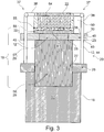
- the vaporizer unit 20 vaporizes liquid 50, which is supplied to it from the liquid reservoir 18, and releases the vaporized liquid as an aerosol / vapor 22 (see FIG Figure 3 ) at an outlet side 64 into the air stream 34.
- An advantageous volume of the liquid reservoir 18 is in the range between 0.1 ml and 5 ml, preferably between 0.5 ml and 3 ml, more preferably between 0.7 ml and 2 ml or 1.5 ml.
- the electronic cigarette 10 further comprises an electrical energy store 14 and an electronic control device 15.
- the energy store 14 is usually arranged in the base part 16 and can in particular be an electrochemical disposable battery or a rechargeable electrochemical battery, for example a lithium-ion battery , be.
- the electronic control device 15 comprises at least one digital data processing device, in particular a microprocessor and / or microcontroller, in the base part 16 (as in Figure 1 shown) and / or in the consumption unit 17.
- a sensor for example a pressure sensor or a pressure or flow switch, is advantageously arranged in the housing 11, the control device 15 being able to determine on the basis of a sensor signal output by the sensor that a consumer is pulling at the mouth end 32 of the cigarette product 10 in order to inhale.
- the control device 15 controls the evaporator unit 20 in order to add liquid 50 from the liquid reservoir 18 as an aerosol / vapor into the air flow 34.
- the liquid 50 to be dosed stored in the liquid reservoir 18 is, for example, a mixture of 1,2-propylene glycol, glycerine, water, at least one aroma (flavor) and / or at least one active ingredient, in particular nicotine.
- the consumption unit or cartridge 17 advantageously comprises a non-volatile data memory for storing information or parameters relating to the consumption unit or cartridge 17.
- the data memory can be part of the electronic control device 15.
- the data memory advantageously contains information about the composition of the liquid stored in the liquid memory 18, information about the process profile, in particular power / temperature control; Data for condition monitoring or system testing, for example leak testing; Data relating to copy protection and protection against forgery, an ID for unambiguous identification of the consumption unit or cartridge 17, serial number, date of manufacture and / or expiry date, and / or number of puffs (number of inhalation puffs by the consumer) or the time of use are stored.
- the data memory is advantageously connected or can be connected to the control device 15 via contacts and / or lines.
- the evaporator unit 20 comprises a block-shaped, preferably monolithic heating element 60, preferably made of an electrically conductive material, preferably silicon, doped ceramic, metal-ceramic, filter ceramic, semiconductors, in particular germanium, graphite, semi-metal and / or metal. It is not necessary for the entire heating element 60 to consist of an electrically conductive material. For example, it may be sufficient that the surface of the heating element 60 is coated in an electrically conductive manner, for example metallic. In this case, the entire surface does not have to be coated; for example, conductor tracks can be provided on a non-conductive base body.
- an electrically conductive material preferably silicon, doped ceramic, metal-ceramic, filter ceramic, semiconductors, in particular germanium, graphite, semi-metal and / or metal. It is not necessary for the entire heating element 60 to consist of an electrically conductive material. For example, it may be sufficient that the surface of the heating element 60 is coated in an electrically conductive manner, for example metallic. In this case,
- the heating body 60 is provided with a plurality of microchannels 62 which connect an inlet side 61 of the heating body 60 to an outlet side 64 in a liquid-conducting manner.
- the inlet side 61 is connected to the liquid reservoir 18 in a liquid-conducting manner via a wick structure 19.
- the wick structure 19 serves to passively convey liquid from a liquid reservoir 50 to the heating element 60 by means of capillary forces.
- the wick structure 19 in the contact area 35, 61 to the heating element 60 serves to distribute liquid evenly, to be temperature-resistant and, with its relatively small pores and / or thin capillaries, to form a kind of check valve to prevent undesired backflow of liquid containing bubbles from the heating element 60 into the wick structure 19 and / or into the liquid reservoir 18.
- the mean diameter of the microchannels 62 is preferably in the range between 5 ⁇ m and 200 ⁇ m, more preferably in the range between 30 ⁇ m and 150 ⁇ m, even more preferably in the range between 50 ⁇ m and 100 ⁇ m.
- a capillary effect is advantageously generated, so that liquid penetrating into a microchannel 62 on the inlet side 61 rises through the microchannel 62 until the microchannel 62 is filled with liquid.
- the volume ratio of microchannels 62 to heating element 60 which can be referred to as the porosity of heating element 60, is, for example, in the range between 10% and 50%, advantageously in the range between 15% and 40%, even more advantageously in the range between 20% and 30 %, and is for example 25%.
- the edge lengths of the surfaces of the heating element 60 provided with microchannels 62 are, for example, in the range between 0.5 mm and 3 mm.
- the dimensions of the surfaces of the heating element 60 provided with microchannels 62 can be, for example: 0.95 mm x 1.75 mm; 1.9 mm x 1.75 mm or 1.9 mm x 0.75 mm.
- the edge lengths of the heating element 60 can for example be in the range between 0.5 mm and 5 mm, preferably in the range between 0.75 mm and 4 mm, more preferably in the range between 1 mm and 3 mm.
- the area of the heater 60 (chip size) can be, for example, 1 mm ⁇ 3 mm or 2 mm ⁇ 3 mm.
- the width b of the radiator 60 is preferably in the range between 1 mm and 5 mm, more preferably in the range between 2 mm and 4 mm, and is, for example, 3 mm.
- the height h of the radiator 60 is preferably in the range between 0.05 mm and 1 mm, more preferably in the range between 0.1 mm and 0.75 mm, even more preferably in the range between 0.2 mm and 0.5 mm and is, for example, 0.3 mm.
- the number of microchannels 62 is preferably in the range between four and 1000. In this way, the heat input from the carrier into the microchannels 62 can be optimized and a guaranteed high evaporation capacity and a sufficiently large vapor exit area can be achieved.
- the microchannels 62 are arranged in the form of a square, rectangular, polygonal, round, oval or other shaped array, as in FIG Figure 3 can be seen.
- the array can be designed in the form of a matrix with s columns and z rows, where s advantageously in the range between 2 and 50 and further advantageously in the range between 3 and 30 and / or z advantageously in the range between 2 and 50 and further advantageously in the range is between 3 and 30.
- the cross section of the microchannels 62 can be square, rectangular, polygonal, round, oval or otherwise shaped, and / or change in sections in the longitudinal direction, in particular increase, decrease or remain constant.
- the length of one or each microchannel 62 is preferably in the range between 100 ⁇ m and 1000 ⁇ m, more preferably in the range between 150 ⁇ m and 750 ⁇ m, even more preferably in the range between 180 ⁇ m and 500 ⁇ m and is, for example, 300 ⁇ m. In this way, optimal liquid absorption and portion formation can be achieved with a sufficiently good heat input from the heating element 60 into the microchannels 62.
- the distance between two microchannels 62 is preferably at least 1.3 times the clear diameter of a microchannel 62, the distance being based on the central axes of the two microchannels 62.
- the distance can preferably be 1.5 to 5 times, more preferably 2 to 4 times the clear diameter of a microchannel 62. In this way, optimal heat input from the carrier into the microchannels and a sufficiently stable arrangement and wall thickness of the microchannels can be achieved.
- the evaporator unit 20 has a heating voltage source 71, preferably controllable by the control device 15, which is connected to the heating element 60 via electrodes 72 on opposite sides of the heating element 60, so that an electrical voltage Uh generated by the heating voltage source 71 leads to a current flow through the heating element 60. Due to the ohmic resistance of the electrically conductive heating element 60, the flow of current leads to heating of the heating element 60 and therefore to an evaporation of the liquid contained in the microchannels 62. The heater 60 thus acts as an evaporator. Steam / aerosol generated in this way escapes to the outlet side 64 from the microchannels 62 and is mixed with the air flow 34, see FIG Figure 1 .
- control device 15 controls the heating voltage source 71, the liquid in the microchannels 62 being driven out of the microchannels 62 in the form of vapor / aerosol by spontaneous heating.
- a voltage curve Uh (t) adapted to the liquid mixture used is preferably stored in the data memory of the inhaler 10. This enables the voltage curve Uh (t) adjusted to the liquid used, so that the heating temperature of the heater 60, and thus also the temperature of the capillary microchannels 62, can be controlled over time via the evaporation process according to the known evaporation kinetics of the respective liquid, whereby optimal evaporation results can be achieved.
- the evaporation temperature is preferably in the range between 100.degree. C. and 400.degree. C., more preferably between 150.degree. C. and 350.degree. C., even more preferably between 190.degree. C. and 290.degree.
- the heating element 60 can advantageously be produced from sections of a wafer using thin-film layer technology, which has a layer thickness of preferably less than or equal to 1000 ⁇ m, more preferably less than or equal to 750 ⁇ m, even more preferably less than or equal to 500 ⁇ m.
- Surfaces of the heating body 60 can advantageously be hydrophilic.
- the outlet side 64 of the heating element 60 can advantageously be microstructured or have micro-grooves.
- the vaporizer unit 20 is set so that an amount of liquid preferably in the range between 1 ⁇ l and 20 ⁇ l, more preferably between 2 ⁇ l and 10 ⁇ l, even more preferably between 3 ⁇ l and 5 ⁇ l, typically 4 ⁇ l per puff of the consumer, is added.
- the evaporator unit 20 can preferably be adjustable with regard to the amount of liquid / vapor per puff.
- a porous and / or capillary, liquid-conducting wick structure 19 is arranged on the inlet side 61 of the heating element 60.
- the wick structure 19 makes flat contact with the inlet side 61 of the heater 60 and covers all of the microchannels 62 on the inlet side, as in FIG Figures 2 , 3 , 6 and 8 can be seen.
- the wick structure is connected to the liquid reservoir in a fluid-conducting manner.
- the ones in the Figures 1 to 3 The shown direct connection of the liquid reservoir 18 to the wick structure 19 is only to be understood as an example. In particular, a liquid interface and / or a plurality of liquid lines can be provided between the liquid reservoir 18 and the wick structure 19.
- the liquid reservoir 18 can therefore also be arranged at a distance from the wick structure 19.
- the dimensions of the liquid reservoir 18 can be larger than the wick structure 19, see for example Figure 3 .
- the wick structure 19 can, for example, be inserted into an opening in a housing of the liquid reservoir 18.
- a plurality of evaporator units 20 can also be assigned to a liquid reservoir 18.
- the wick structure 19 consists of porous and / or capillary material which, due to capillary forces, is able to passively replenish liquid evaporated by the heating element 60 in sufficient quantities from the liquid reservoir 18 to the heating element 60 in order to empty the microchannels 62 and out of it prevent resulting problems.
- the wick structure 19 advantageously consists of a non-conductive material in order to avoid undesired heating of liquid in the wick structure 19 due to the flow of current. If the wick structure 19 consists of a conductive material, which is not excluded, an insulating layer made of an electrically and / or thermally insulating material, for example glass, ceramic or plastic, with extending through the insulating layer is advantageous between the wick structure 19 and the heating element 60 , with the Microchannels 62 corresponding through openings are provided.
- the wick structure 19 advantageously consists of one or more of the materials cotton, cellulose, acetate, glass fiber fabric, glass fiber ceramic, sintered ceramic, ceramic paper, aluminosilicate paper, metal foam, metal sponge, another heat-resistant, porous and / or capillary material with a suitable delivery rate, or a Composite of two or more of the aforementioned materials.
- the wick structure 19 can comprise at least one ceramic fiber paper and / or a porous ceramic.
- the volume of the wick structure 19 is preferably in the range between 1 mm 3 and 10 mm 3 , more preferably in the range between 2 mm 3 and 8 mm 3 , even more preferably in the range between 3 mm 3 and 7 mm 3 and is, for example, 5 mm 3 .
- FIGS Figures 3 to 8 Advantageous embodiments of an evaporator unit 20 are shown in FIGS Figures 3 to 8 shown.
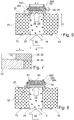
- the wick structure 19 can generally be made in one piece, see FIG Figure 8 , or be in several parts, see Figures 3 and 6th .
- the wick structure 19 is, for example, two-layered with a wick layer 35, which is in flat contact with the inlet side 61 of the heating element 60, and a further wick layer 36 lying flat thereon.
- the wick layer 35 can preferably be a fiber paper or ceramic paper layer, with or without a glass filter filter, be.
- the wick layer 36 can preferably be a porous ceramic.
- the wick structure 19 comprises more than two, for example four layers.
- a filter layer 55 is arranged on the heating element 60, and in flat contact with it, which can in particular consist of one, two or more micro-glass fiber layers.
- a fiber paper layer 56 can be arranged flatly adjacent to this.
- wick layers 57, 58 are advantageously provided, for example a ceramic wick layer 57 and an oil lamp wick layer 58, ie a glass fiber wick material that is conventionally used for the wicks of oil lamps.
- the capillary forces for the capillary conveyance of the liquid from the liquid reservoir 18 to the heating element 60 can be provided predominantly or completely by the wick layers 57, 58. It is generally not necessary if all layers of the wick structure 19 provide capillary forces for the capillary conveyance of the liquid. It can also be sufficient that only one layer of the wick structure 19 provides capillary forces for the capillary conveyance of the liquid.
- the evaporator unit 20 has an in particular plate-shaped carrier 23 for holding the heating element 19 and / or the wick structure 19, as in FIG Figures 3 to 8 is shown.
- the carrier 23 can consist of a suitable material, for example ceramic, glass and / or plastic including fiber-reinforced plastic, for example printed circuit board material, and has a through opening 25 through which the wick structure 19 extends and in which the wick structure 19 is held.
- the thickness D of the carrier 23 is preferably in the range between 0.5 mm to 4 mm, more preferably in the range between 1 mm to 3 mm, even more preferably in the range between 1 mm and 2 mm and can for example be 1.6 mm or 2 mm be.
- the thickness of a wick layer 57 arranged in the through opening 25 of the carrier 23 can be adapted to or correspond to the thickness of the carrier 23 and therefore also be 1.6 mm or 2 mm, for example.
- the through opening 25 is advantageously circular, which is easy to manufacture.
- the diameter d, or possibly the mean diameter, of the through opening 25 is preferably in the range between 0.5 mm and 4 mm, preferably in the range between 1 mm to 3 mm, more preferably in the range between 1.5 mm and 2.5 mm and is, for example, 2 mm.
- the diameter d of the through opening 25 is smaller than or equal to, advantageously smaller than the width b of the heating element 60, see Figure 6 .
- the volume of the through opening 25 or the wick volume in the through opening 25 is advantageously in the range between 1 mm 3 and 8 mm 3 , preferably in the range between 2 mm 3 and 6.5 mm 3 , more preferably in the range between 2.5 mm 3 and 5 mm 3 .
- the wick structure 19 has a collar-shaped section or collar 28 and a shaft section or shaft 29, or consists of these components 28, 29.
- the collar 28 is arranged between the heating element 60 and the carrier 23, rests flat against the heating element 60 on the inlet side 61 and thereby covers all of the microchannels 62.
- the thickness s of the collar is advantageously in the range between 0.05 mm and 1 mm and is preferably at most 0.8 mm, more preferably at most 0.6 mm, even more preferably at most 0.4 mm and, for example, 0.2 mm.
- the shaft section 29 rests flat against the collar 28 on its side facing away from the heating element 60.
- the real or imaginary separating surface between collar 28 and shaft section 29 can lie in one plane with the surface of carrier 23 facing heating element 60.
- the shaft section 29 can in particular denote the remaining part of the wick section 19, apart from the collar 28.
- the shaft section 29 can have an oversize, i.e. a larger diameter than the through opening 25, in order to generate additional holding forces for the shaft 29 in the through opening 25.
- Collar 28 and shaft 29 can be formed in one piece or in one piece, see Figure 8 .
- the collar 28 and the shaft 29 can also each be separate parts and be formed by corresponding wick sections 35, 36, see FIG Figure 6 .
- Figure 3 shows that collar 28 and / or shaft 29 can each be constructed in several parts and can each be formed by corresponding wick sections 55, 56 or 57, 58.
- the diameter t of the collar 28 (see Figure 6 ) is larger than the diameter d of the through opening 25 and thus of the shaft 29 in the region of the through opening 25.
- the collar 28 preferably projects over its entire circumference over the through opening 25 with a protrusion k.
- the protrusion k of the collar 28 over the through opening 25 is preferably at least 0.1 mm, more preferably at least 0.2 mm, even more preferably at least 0.3 mm and particularly preferably at least 0.4 mm.
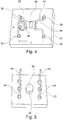
- the heating element 60 is clamped on the carrier 23 by means of at least two clamping elements 37, see in particular Figure 4 that attack on opposite sides of the heater 60 on this.
- Each clamping element 37 advantageously has a clamping bracket 38 which is resiliently fastened to the support 23 at two spaced apart fastening points 39 and generates a pretension by means of which the heating element 60 and the collar 28 are clamped on the support 23.
- the distance a between the two fastening points 39 of a clamping bracket 38 is preferably in the range between 4 mm and 10 mm, more preferably in the range between 5 mm to 8 mm and is, for example, 6 mm.
- the distance c between the fastening points 39 of two clamps 39 from one another is preferably in the range between 5 mm and 12 mm, more preferably in the range between 6 mm to 10 mm and is, for example, 8 mm.
- the dimensions of the, for example, rectangular carrier 23 are preferably in the range between 6 mm and 20 mm, more preferably in the range between 8 mm to 17 mm and even more preferably in the range between 10 mm and 14 mm.
- the clamping elements 37 are particularly advantageously used at the same time as electrodes for contacting the heating element 60 and supplying it with heating current.
- the clamping elements 37 or the clamping brackets 38 are advantageously made of an electrically conductive material, for example it can be metal wire, for example brass wire. Because of the line contact Between the clamping bracket 38 and the heating element 60 there is an excellent electrical connection between the clamping element 37 and the heating element 60, with at the same time ideal thermal decoupling between the clamping element 37 and the heating element 60 due to the lack of surface contact. Heat dissipation from the heating element 60 into the clamping element 37 is therefore low, the electrodes 38 remain significantly cooler than the heating element 60.
- the clamping bracket 38 can move the heating element 60 laterally parallel to the outlet side 64 (position 38A in Figure 6 ) and / or perpendicular to the outlet side 64 (position 38B in Figure 6 ) and / or in a groove or step with an intermediate angle, for example between 30 ° and 60 °, both laterally and vertically on the outlet side 64 (position 38C in Figure 6 ).
- the latter possibility involves two contact lines between the clamping bracket 38C and the heating element 60, which further improves the electrical contact.
- a clamping element 37 can also have more than one clamping bracket 38, in particular any two or all three of the clamping brackets 38A, 38B, 38C.
- the clamping elements 37 are advantageously connected by means of electrical lines 12 to a printed circuit board 26 (PCB) provided in the consumer unit 17 in order to establish the electrical connection to the electronic control device 15 and to the energy source 46 for the power supply of the heater 60.
- PCB printed circuit board 26
- Electronic components of the consumer unit 17 are advantageously arranged on the circuit board 26.
- the circuit board 26 is in accordance with the exemplary embodiment Figure 3 a separate part and arranged at a distance from the carrier 23 on its side 43 facing away from the heating element 60.
- the circuit board 26 has a through opening 27 through which the shaft 29 of the wick structure 19 extends and in which the wick structure 19 can be held.
- the electrical lines 12 here include, for example, four metal pins 44, which are connected to the clamping elements 37 on the side 33 of the carrier 23 in the fastening points 39 and are each passed through a through hole 45 through the carrier 23 and then on the opposite side 43 the distance between the carrier 23 and the circuit board 26 bridge.
- the carrier 23 can form the printed circuit board 26.
- the electrical lines 12 can then be omitted.
- the evaporator unit 20 itself does not comprise a printed circuit board, but rather that the clamping brackets 38 are connected, for example, via flexible insulated lines 12 or in another suitable manner, to a printed circuit board arranged in the base part 16, for example.
- a recess 74 adapted to the collar 28 can be provided on the upper side 33 of the carrier 23, into which the collar 28 can be precisely inserted during assembly in order to define an optimal assembly position of the collar 28.
- a sealing element 73 for example a sealing ring, can be arranged on the underside 43 of the carrier 23 for sealing the carrier 23 against a housing of the liquid reservoir 18 or another component arranged below the carrier 23, see Figures 6 and 8 .
- the control frequency of the heating element 60 generated by the heating voltage source 71 is advantageously in the range from 1 Hz to 50 kHz, preferably in the range from 30 Hz to 30 kHz, even more advantageously in the range from 100 Hz to 25 kHz.
- the voltage source 71 for the heating process is switched off.
- voltage source 71 for heating element 60 is activated.
- the voltage Uh is set in such a way that the evaporation temperature in the heating element 60 and thus in the microchannels 62 is adapted to the individual evaporation behavior of the liquid mixture used. This prevents the risk of local overheating and the creation of pollutants.
- the heating voltage source 71 is deactivated. Since the properties and quantity of the liquid are advantageously known exactly, this point in time can be controlled very precisely. The energy consumption of the evaporator unit 20 can therefore be reduced compared to known devices, since the required evaporation energy can be introduced in a more metered and thus more precise manner. Due to the design of the heating element 60, it can also be referred to as a volume evaporator, in contrast to conventional surface evaporators.
- the microchannels 62 are predominantly or completely emptied.
- the heating voltage 71 is then kept switched off until, by means of replenishment of Liquid through the wick structure 19, the microchannels 62 are refilled. As soon as this is the case, the next heating cycle can be started by switching on the heating voltage 71.
- the evaporator unit 20 is preferably manufactured on the basis of MEMS technology, in particular from silicon, and is therefore advantageously a micro-electro-mechanical system.
Description
Die vorliegende Erfindung betrifft eine Verdampfereinheit für einen Inhalator, insbesondere für ein elektronisches Zigarettenprodukt, mit einem elektrisch betreibbaren, insbesondere planaren Heizkörper, der eine Einlassseite und eine Auslassseite aufweist, und einer Mehrzahl von Mikrokanälen, die sich jeweils von der Einlassseite zu der Auslassseite durch den Heizkörper erstrecken, wobei der Heizkörper durch Anlegen einer Heizspannung zum Verdampfen von durch die Mikrokanäle geförderter Flüssigkeit eingerichtet ist.The present invention relates to a vaporizer unit for an inhaler, in particular for an electronic cigarette product, with an electrically operated, in particular planar heating element, which has an inlet side and an outlet side, and a plurality of microchannels, each of which extends from the inlet side to the outlet side through the Extending heating body, wherein the heating body is set up by applying a heating voltage to evaporate liquid conveyed through the microchannels.
Im Stand der Technik erfolgt die Liquidzufuhr zum Heizkörper typischerweise kapillar mittels eines Dochts. Die verwendeten Dochte haben entlang der Förderrichtung idealerweise eine konstante Förderwirkung. Ist die Förderrate geringer als die geforderte Verdampfungsrate, so trocknet der Docht in direkter Nähe zum Heizkörper aus. Es folgt ein Trockenzug (sogenannter Dry Puff) und Schadstoffe werden freigesetzt.In the prior art, the liquid is typically supplied to the radiator by capillary means by means of a wick. The wicks used ideally have a constant conveying effect along the conveying direction. If the delivery rate is lower than the required evaporation rate, the wick dries out in the direct vicinity of the radiator. This is followed by a dry puff and pollutants are released.
Im Falle eines planaren Heizkörpers muss der Heizkörper zu jeder Zeit und an jedem Ort durch den Docht möglichst gleichmäßig benetzt werden, um eine konstante Temperaturverteilung und damit gleichmäßige, schadstofffreie Verdampfung über seine Oberfläche zu gewährleisten.
Die Aufgabe der Erfindung besteht darin, eine jederzeit funktionssichere Verdampfereinheit mit hoher thermo-elektromechanischer Stabilität bereitzustellen, mit der die Entstehung von Schadstoffen bei der Verdampfung von Flüssigkeit vermieden werden kann.The object of the invention is to provide an evaporator unit that is functionally reliable at all times and has a high level of thermo-electromechanical Provide stability with which the formation of pollutants in the evaporation of liquid can be avoided.
Die Erfindung löst diese Aufgabe mit den Merkmalen der unabhängigen Ansprüche.The invention solves this problem with the features of the independent claims.
Erfindungsgemäß ist an der Einlassseite des Heizkörpers eine poröse und/oder kapillare Dochtstruktur angeordnet, die flüssigkeitsleitend mit einem Flüssigkeitsspeicher verbunden oder verbindbar ist. Die Dochtstruktur weist einen sich durch eine Durchgangsöffnung des Trägers erstreckenden Schaft und einen zwischen dem Träger und dem Heizkörper angeordneten umlaufenden Kragen auf. Der Durchmesser des Kragens ist erfindungsgemäß größer ist als der Durchmesser der Durchgangsöffnung des Trägers. Der Kragen kann daher auf dem die Durchgangsöffnung bildenden Teil des Trägers aufliegen und auf diese Weise die Dochtstruktur halten, da der Kragen aufgrund der erfindungsgemäßen Bemaßung nicht durch die Durchgangsöffnung in Richtung Flüssigkeitsspeicher auswandern kann, was die Funktionalität der Verdampfereinheit beeinträchtigen würde.According to the invention, a porous and / or capillary wick structure is arranged on the inlet side of the heating element, which is connected or can be connected to a liquid reservoir in a liquid-conducting manner. The wick structure has a shaft extending through a through opening of the carrier and a circumferential collar arranged between the carrier and the heating element. According to the invention, the diameter of the collar is greater than the diameter of the through opening of the carrier. The collar can therefore rest on the part of the carrier that forms the through opening and in this way hold the wick structure, since the collar cannot migrate through the through opening in the direction of the liquid reservoir due to the dimensions according to the invention, which would impair the functionality of the evaporator unit.
Vorzugsweise ist mindestens ein Vorspannungs-erzeugendes Klemmelement vorgesehen, das zur Klemmung des Heizkörpers und des Kragens auf den Träger angeordnet und eingerichtet ist. Mittels des Klemmelements wird der der Kragen der Dochtstruktur zwischen dem Heizkörper und dem Träger eingeklemmt und auf diese Weise die Dochtstruktur sicher und unverrückbar in der Verdampfereinheit gehalten. Es ist dabei besonders vorteilhaft, wenn der Kragen über seinen gesamten Umfang über die Durchgangsöffnung des Trägers übersteht, vorzugsweise mit einem Überstand von mindestens 0,1 mm oder mehr. Durch den allseitigen Überstand wird eine gleichmäßige Klemmung erreicht und Leckage vermieden.Preferably, at least one preload-generating clamping element is provided, which is arranged and set up to clamp the heating element and the collar onto the carrier. The collar of the wick structure is clamped between the heating element and the carrier by means of the clamping element and in this way the wick structure is held securely and immovably in the evaporator unit. It is particularly advantageous if the collar protrudes over its entire circumference over the through opening of the carrier, preferably with a protrusion of at least 0.1 mm or more. The overhang on all sides creates a even clamping achieved and leakage avoided.
In einer besonders bevorzugten Ausführungsform dient das mindestens eine Klemmelement gleichzeitig als Elektrode zur elektrischen Kontaktierung und Versorgung des Heizkörpers. In diesem Fall sind separate Elektroden für die elektrische Kontaktierung des Heizkörpers entbehrlich.In a particularly preferred embodiment, the at least one clamping element simultaneously serves as an electrode for making electrical contact with and supplying the heating element. In this case, separate electrodes for making electrical contact with the heater are not required.
Vorzugsweise sind mindestens zwei Klemmelemente auf gegenüberliegenden Seiten des Heizkörpers vorgesehen, was eine besonders hohe mechanische Stabilität mit relativ geringem Aufwand ermöglicht. In einer bevorzugten Ausführungsform weist das mindestens eine Klemmelement einen den Heizkörper linienförmig kontaktierenden Klemmbügel auf. Aufgrund der Linienkontaktierung zwischen dem Klemmbügel und dem Heizkörper ergibt sich eine ausgezeichnete elektrische Verbindung zwischen dem Klemmelement und dem Heizkörper, bei gleichzeitig idealer thermischer Entkopplung zwischen dem Klemmelement und dem Heizkörper wegen fehlendem Flächenkontakt.At least two clamping elements are preferably provided on opposite sides of the heater, which enables particularly high mechanical stability with relatively little effort. In a preferred embodiment, the at least one clamping element has a clamping bracket that makes linear contact with the heating element. Due to the line contact between the clamp and the heater, there is an excellent electrical connection between the clamp and the heater, while at the same time ideal thermal decoupling between the clamp and the heater due to the lack of surface contact.
Das Klemmelement kann den Heizkörper seitlich parallel zur Auslassseite und/oder senkrecht auf die Auslassseite und/oder in einer Nut oder Stufe des Trägers klemmen. Die letztgenannte Möglichkeit involviert zwei Kontaktlinien zwischen dem Klemmbügel und dem Heizkörper, was die elektrische Kontaktierung weiter erheblich verbessert. Ein Klemmelement kann auch mehr als einen Klemmbügel aufweisen, insbesondere beliebige zwei oder alle drei Klemmbügel der vorgenannten Art.The clamping element can clamp the heating element laterally parallel to the outlet side and / or perpendicular to the outlet side and / or in a groove or step in the carrier. The latter option involves two contact lines between the clamping bracket and the heating element, which further improves the electrical contact considerably. A clamping element can also have more than one clamping bracket, in particular any two or all three clamping brackets of the aforementioned type.
In einer vorteilhaften Ausführungsform kann mindestens ein sich durch eine Bohrung des Trägers erstreckender elektrischer Leiter zur elektrischen Kontaktierung des Klemmelements vorgesehen sein, der insbesondere eine Leiterplatte kontaktiert, die auf der von dem Heizkörper abgewandten Seite des Trägers beabstandet angeordnet ist . Es ist aber auch vorteilhaft möglich, dass der Träger selbst als Leiterplatte ausgebildet ist, was die Anzahl der Teile und somit den Herstellungsaufwand reduziert.In an advantageous embodiment, at least one electrical conductor extending through a bore in the carrier can be used be provided for making electrical contact with the clamping element, which contacts in particular a printed circuit board which is arranged at a distance on the side of the carrier facing away from the heating element. However, it is also advantageously possible for the carrier itself to be designed as a printed circuit board, which reduces the number of parts and thus the manufacturing effort.
Nach alledem wird vorteilhaft ein insbesondere planarer Silizium-Heizkörper bereitgestellt, der die Dochtstruktur so auf den Träger klemmt, dass die Dochtstruktur mechanisch fixiert ist, eine sichere luftundurchlässige hydraulische Kopplung zwischen dem Heizkörper und dem Flüssigkeitsreservoir entsteht, und gleichzeitig die elektrische Ankopplung des Heizkörpers gewährleistet ist. Heizkörper und Reservoir befinden sich an gegenüberliegenden Seiten des Dochts.After all this, a particularly planar silicon heating element is advantageously provided, which clamps the wick structure onto the carrier in such a way that the wick structure is mechanically fixed, a reliable, air-impermeable hydraulic coupling is created between the heating element and the liquid reservoir, and at the same time the electrical connection of the heating element is ensured . The heater and reservoir are on opposite sides of the wick.
Der Kragen kann vorteilhaft ein Teller, ein Flansch oder ein in einer anderen Ebene umlaufender Kragen sein. Im Falle eines Tellers ist die Dochtstruktur somit pilzförmig ausgebildet. Der erfindungsgemäße Kragen ermöglicht eine Klemmung der Dochtstruktur zwischen dem Träger und Heizkörper bei gleichzeitiger Liquidleitung durch die Durchgangsöffnung des Trägers. Der Heizkörper ist durch die Dochtstruktur thermisch vom Träger isoliert, gleichzeitig stellt die Klemmung durch elektrische Leiter auch die Stromversorgung des Heizkörpers dar. Die elektrische Verbindung übt einen Anpressdruck auf Heizkörper und Dochtstruktur aus, welcher thermischen Drücken während der Verdampfung entgegenwirkt.The collar can advantageously be a plate, a flange or a collar running around in another plane. In the case of a plate, the wick structure is thus mushroom-shaped. The collar according to the invention enables the wick structure to be clamped between the support and the heating element with simultaneous conduction of liquid through the through-opening of the support. The heating element is thermally insulated from the carrier by the wick structure, at the same time the clamping by electrical conductors also provides the power supply for the heating element. The electrical connection exerts contact pressure on the heating element and the wick structure, which counteracts thermal pressures during evaporation.
Wesentlich ist eine flüssigkeitsleitende Anlage zwischen einer Dochtfläche und einer Fläche des Heizkörpers, die den Kragen vorteilhaft einbeziehen kann, aber nicht unbedingt muss. Der Träger kann beispielsweise auch von einer, gegebenenfalls verbreiterten, Gehäusewand des Flüssigkeitsreservoirs ausgebildet sein. In diesem Fall kann ein separater Träger entbehrlich sein.What is essential is a fluid-conducting system between a wick surface and a surface of the heating element, which can advantageously include the collar, but does not necessarily have to. The carrier can, for example, also consist of an, optionally widened, Be formed housing wall of the liquid reservoir. In this case, a separate carrier can be dispensed with.
Mittels der Dochtstruktur kann der Blasenbildung im Einlassbereich des Heizkörpers entgegenwirkt werden. Bläschen, die in den Mikrokanälen des Heizkörpers entstehen, können nicht in den Bereich stromaufwärts von der Einlassseite vordringen und zu einem Trockenlaufen des Einlassbereichs des Heizkörpers, und somit zu einer Funktionsbeeinträchtigung des Verdampfers führen. Etwaige Bläschen im Bereich der Dochtstruktur sind in deren Poren bzw. Kapillaren gefangen und können sich nicht großen Blasen vereinigen. Wichtig ist dabei, dass die Dochtstruktur flächig und kontaktierend an der Einlassseite an dem Heizkörper anliegt und sämtliche Mikrokanäle an der Einlassseite überdeckt, damit einzelne Bläschen, die in den Mikrokanälen entstehen, nicht in der falschen Richtung, nämlich auf der Einlassseite zum Flüssigkeitsspeicher hin, aus den Mikrokanälen austreten können. Vielmehr sorgt die Blockade der Einlassseite durch die erfindungsgemäße Dochtstruktur dafür, dass in den Mikrokanälen entstehende Bläschen in den Mikrokanälen zur Auslassseite hin wandern, wo sie aus den Mikrokanälen ausgetrieben werden und dann keine Probleme mehr bereiten können.The wick structure can counteract the formation of bubbles in the inlet area of the heater. Bubbles that arise in the microchannels of the heating element cannot penetrate into the area upstream of the inlet side and lead to the inlet area of the heating element running dry and thus impairing the function of the evaporator. Any bubbles in the area of the wick structure are trapped in their pores or capillaries and cannot unite large bubbles. It is important that the wick structure lies flat and in contact on the inlet side of the heating element and covers all microchannels on the inlet side so that individual bubbles that arise in the microchannels do not escape in the wrong direction, namely on the inlet side towards the liquid reservoir can escape the microchannels. Rather, the blockage of the inlet side by the wick structure according to the invention ensures that bubbles formed in the microchannels migrate in the microchannels to the outlet side, where they are expelled from the microchannels and can then no longer cause problems.
Dabei kann die Dauer der einzelnen Verdampfungsschritte bei unterschiedlichen Temperaturen und/oder einem Verdampfen der einzelnen Komponenten der einzelnen Portionen der Flüssigkeit derart kurz gehalten werden und/oder mit einer Ansteuerfrequenz getaktet erfolgen, dass die schrittweise Verdampfung von einem Konsumenten nicht wahrgenommen und trotzdem eine weitgehend homogene, geschmackskonforme, wiederholbar präzise Aerosolbildung gewährleistet werden kann. Insbesondere erfolgt vorteilhaft zunächst ein Verdampfen einer leichter siedenden Komponente der Flüssigkeit in einem ersten Verdampfungsintervall mit einer ersten Temperatur A und anschließend ein Verdampfen einer höher siedenden Komponente der Flüssigkeit in einem zweiten Verdampfungsintervall mit einer zweiten Temperatur B, welche die Temperatur A übersteigt.The duration of the individual evaporation steps at different temperatures and / or an evaporation of the individual components of the individual portions of the liquid can be kept so short and / or clocked with a control frequency that the step-by-step evaporation is not perceived by a consumer and is nevertheless largely homogeneous , taste-conforming, repeatable, precise aerosol formation can be guaranteed. In particular, a lower-boiling component of the liquid is advantageously first evaporated a first evaporation interval with a first temperature A and then evaporation of a higher-boiling component of the liquid in a second evaporation interval with a second temperature B which exceeds the temperature A.
Vorteilhaft ist die Förderrate der Dochtstruktur mindestens so groß ist wie die maximale Verdampfungsrate des Heizkörpers. Damit wird jederzeit eine ausreichende Flüssigkeitsnachführung sichergestellt, so dass ein nachteiliges Leerlaufen des Heizkörpers verhindert wird. Die Verdampfungsrate wird dabei bestimmt durch die Geometrie der Heizkörperstruktur (Volumen vs. Oberfläche) und die Verdampferleistung.The delivery rate of the wick structure is advantageously at least as great as the maximum evaporation rate of the heating element. In this way, sufficient liquid replenishment is ensured at all times, so that disadvantageous emptying of the heating element is prevented. The evaporation rate is determined by the geometry of the radiator structure (volume vs. surface) and the evaporator output.
Demnach ist die kapillare Dochtstruktur eingerichtet, um das Liquid gleichmäßig über ihr gesamtes Volumen zum Heizkörper fördern. Förderrate der Dochtstruktur und Verdampfungsrate des Heizkörpers sind so zueinander eingestellt, dass die Förderrate mindestens die Verdampfungsrate bedienen kann. Auf diese Weise wird verhindert, dass während des Verdampfungsvorgangs zu wenig Liquid am Heizkörper anliegt, wodurch dieser austrocknen würde.Accordingly, the capillary wick structure is set up to convey the liquid evenly over its entire volume to the radiator. The delivery rate of the wick structure and the evaporation rate of the heating element are set in relation to one another in such a way that the delivery rate can at least serve the evaporation rate. In this way, it is prevented that too little liquid is on the radiator during the evaporation process, which would dry it out.
Die Dochtstruktur kann aus jedem hinreichend hitzebeständigen, porösen und/oder kapillaren Material mit geeigneter Förderrate bestehen. Vorteilhaft kann die Dochtstruktur ganz oder teilweise bestehen aus Baumwolle, Cellulose, Acetat, Glasfasergewebe, Glasfaserkeramik, Sinterkeramik, keramisches Papier, Alumosilikat-Papier, Metallschaum, Metallschwamm, und/oder einem Verbund von zwei oder mehr der vorgenannter Materialien.The wick structure can consist of any sufficiently heat-resistant, porous and / or capillary material with a suitable delivery rate. The wick structure can advantageously consist entirely or partially of cotton, cellulose, acetate, glass fiber fabric, glass fiber ceramic, sintered ceramic, ceramic paper, aluminosilicate paper, metal foam, metal sponge, and / or a composite of two or more of the aforementioned materials.
Die Erfindung wird im Folgenden anhand bevorzugter Ausführungsformen unter Bezugnahme auf die beigefügten Figuren erläutert.The invention is explained below on the basis of preferred embodiments with reference to the accompanying figures.
Dabei zeigt
- Fig. 1
- eine schematische Darstellung eines elektronischen Zigarettenprodukts;
- Fig. 2
- eine perspektivische Querschnittsansicht einer Verdampfereinheit;
- Fig. 3
- eine schematische Querschnittsansicht einer Verdampfereinheit in einer Ausführungsform der Erfindung;
- Fig. 4, 5
- Aufsicht auf den Träger einer Verdampfereinheit von der Seite des Heizkörpers (
Figur 4 ) und von der entgegengesetzten Seite der Flüssigkeitszuführung (Figur 5 ); - Fig. 6, 8
- Querschnittsansichten einer Verdampfereinheit in weiteren Ausführungsformen der Erfindung; und
- Figur 7
- ein Ausschnitt aus
Figur 6 im Bereich des Überstands des Docht-Kragens über die Durchgangsöffnung des Trägers.
- Fig. 1
- a schematic representation of an electronic cigarette product;
- Fig. 2
- a perspective cross-sectional view of an evaporator unit;
- Fig. 3
- a schematic cross-sectional view of an evaporator unit in an embodiment of the invention;
- Fig. 4, 5
- Top view of the support of an evaporator unit from the side of the radiator (
Figure 4 ) and from the opposite side of the liquid inlet (Figure 5 ); - Fig. 6, 8
- Cross-sectional views of an evaporator unit in further embodiments of the invention; and
- Figure 7
- a section from
Figure 6 in the area of the protrusion of the wick collar over the through opening of the carrier.
Der Inhalator 10, hier ein elektronisches Zigarettenprodukt, umfasst ein Gehäuse 11, in dem ein Luftkanal 30 zwischen mindestens einer Lufteinlassöffnung 31 und einer Luftauslassöffnung 24 an einem Mundende 32 des Zigarettenprodukts 10 vorgesehen ist. Das Mundende 32 des Zigarettenprodukts 10 bezeichnet dabei das Ende, an dem der Konsument zwecks Inhalation zieht und dadurch das Zigarettenprodukt 10 mit einem Unterdruck beaufschlagt und eine Luftströmung 34 in dem Luftkanal 30 erzeugt.The
Das Zigarettenprodukt 10 besteht vorteilhaft aus einem Basisteil 16 und einer Verbrauchseinheit 17, die die Verdampfereinheit 20 und den Flüssigkeitsspeicher 18 umfasst und insbesondere in Form einer auswechselbaren Kartusche ausgebildet ist. Die durch die Einlassöffnung 31 angesaugte Luft wird in dem Luftkanal 30 zu oder entlang mindestens einer Verdampfereinheit 20 geleitet. Die Verdampfereinheit 20 ist mit mindestens einem Flüssigkeitsspeicher 18 verbunden oder verbindbar, in dem mindestens eine Flüssigkeit 50 gespeichert ist. Die Verdampfereinheit 20 verdampft Flüssigkeit 50, die ihr aus dem Flüssigkeitsspeicher 18 zugeführt wird, und gibt die verdampfte Flüssigkeit als Aerosol/Dampf 22 (siehe
Die elektronische Zigarette 10 umfasst des Weiteren einen elektrischen Energiespeicher 14 und eine elektronische Steuerungsvorrichtung 15. Der Energiespeicher 14 ist in der Regel in dem Basisteil 16 angeordnet und kann insbesondere eine elektrochemische Einweg-Batterie oder ein wiederaufladbarer elektrochemischer Akku, beispielsweise ein Lithium-lonen-Akku, sein. Die elektronische Steuerungsvorrichtung 15 umfasst mindestens eine digitale Datenverarbeitungseinrichtung, insbesondere Mikroprozessor und/oder Mikrocontroller, in dem Basisteil 16 (wie in
In dem Gehäuse 11 ist vorteilhaft ein Sensor, beispielsweise ein Drucksensor oder ein Druck- oder Strömungsschalter, angeordnet, wobei die Steuerungsvorrichtung 15 auf der Grundlage eines von dem Sensor ausgegebenen Sensorsignals feststellen kann, dass ein Konsument am Mundende 32 des Zigarettenprodukts 10 zieht, um zu inhalieren. In diesem Fall steuert die Steuerungsvorrichtung 15 die Verdampfereinheit 20 an, um Flüssigkeit 50 aus dem Flüssigkeitsspeicher 18 als Aerosol/Dampf in den Luftstrom 34 zuzugeben.A sensor, for example a pressure sensor or a pressure or flow switch, is advantageously arranged in the
Die in dem Flüssigkeitsspeicher 18 gespeicherte, zu dosierende Flüssigkeit 50 ist beispielsweise eine Mischung aus 1,2-Propylenglykol, Glycerin, Wasser, mindestens einem Aroma (Flavour) und/oder mindestens einem Wirkstoff insbesondere Nikotin.The liquid 50 to be dosed stored in the
Die Verbrauchseinheit bzw. Kartusche 17 umfasst vorteilhaft einen nichtflüchtigen Datenspeicher zum Speichern von die Verbrauchseinheit bzw. Kartusche 17 betreffender Information bzw. Parameter. Der Datenspeicher kann Teil der elektronischen Steuerungsvorrichtung 15 sein. In dem Datenspeicher ist vorteilhaft Information zur Zusammensetzung der in dem Flüssigkeitsspeicher 18 gespeicherten Flüssigkeit, Information zum Prozessprofil, insbesondere Leistungs-/Temperatursteuerung; Daten zur Zustandsüberwachung bzw. Systemprüfung, beispielsweise Dichtigkeitsprüfung; Daten betreffend Kopierschutz und Fälschungssicherheit, eine ID zur eindeutigen Kennzeichnung der Verbrauchseinheit bzw. Kartusche 17, Seriennummer, Herstelldatum und/oder Ablaufdatum, und/oder Zugzahl (Anzahl der Inhalationszüge durch den Konsumenten) bzw. der Nutzungszeit gespeichert. Der Datenspeicher ist vorteilhaft über Kontakte und/oder Leitungen mit der Steuereinrichtung 15 verbunden oder verbindbar.The consumption unit or
Eine vorteilhafte Ausführungsform einer erfindungsgemäßen Verdampfereinheit 20 ist in
Der Heizkörper 60 ist mit einer Mehrzahl von Mikrokanälen 62 versehen, die eine Einlassseite 61 des Heizkörpers 60 mit einer Auslassseite 64 flüssigkeitsleitend verbinden. Die Einlassseite 61 ist über eine Dochtstruktur 19 flüssigkeitsleitend mit dem Flüssigkeitsspeicher 18 verbunden. Die Dochtstruktur 19 dient zur passiven Förderung von Flüssigkeit aus einem Flüssigkeitsspeicher 50 zu dem Heizkörper 60 mittels Kapillarkräften. Die Dochtstruktur 19 im Kontaktbereich 35, 61 zu dem Heizkörper 60 dient dazu, Flüssigkeit gleichmäßig zu verteilen, temperaturbeständig zu sein und mit ihren relativ kleinen Poren und/oder dünnen Kapillaren eine Art Rückschlagventil zu bilden, um unerwünschtes Rückfließen von blasenhaltiger Flüssigkeit aus dem Heizkörper 60 in die Dochtstruktur 19 und/oder in den Flüssigkeitsspeicher 18 zu verhindern.The
Der mittlere Durchmesser der Mikrokanäle 62 liegt vorzugsweise im Bereich zwischen 5 µm und 200 µm, weiter vorzugsweise im Bereich zwischen 30 µm und 150 µm, noch weiter vorzugsweise im Bereich zwischen 50 µm und 100 µm. Aufgrund dieser Abmessungen wird vorteilhaft eine Kapillarwirkung erzeugt, so dass an der Einlassseite 61 in einen Mikrokanal 62 eindringende Flüssigkeit durch den Mikrokanal 62 nach oben steigt, bis der Mikrokanal 62 mit Flüssigkeit gefüllt ist. Das Volumenverhältnis von Mikrokanälen 62 zu Heizkörper 60, das als Porosität des Heizkörpers 60 bezeichnet werden kann, liegt beispielsweise im Bereich zwischen 10% und 50%, vorteilhaft im Bereich zwischen 15% und 40%, noch weiter vorteilhaft im Bereich zwischen 20% und 30%, und beträgt beispielsweise 25%.The mean diameter of the
Die Kantenlängen der mit Mikrokanälen 62 versehenen Flächen des Heizkörpers 60 liegen beispielsweise im Bereich zwischen 0,5 mm und 3 mm. Die Abmessungen der mit Mikrokanälen 62 versehenen Flächen des Heizkörpers 60 können beispielsweise betragen:
0,95 mm x 1,75 mm; 1,9 mm x 1,75 mm oder 1,9 mm x 0,75 mm. Die Kantenlängen des Heizkörpers 60 können beispielsweise im Bereich zwischen 0,5 mm und 5 mm liegen, vorzugsweise im Bereich zwischen 0,75 mm und 4 mm, weiter vorzugsweise im Bereich zwischen 1 mm und 3 mm liegen. Die Fläche des Heizkörpers 60 (chip size) kann beispielsweise 1 mm x 3 mm oder 2 mm x 3 mm betragen.The edge lengths of the surfaces of the
0.95 mm x 1.75 mm; 1.9 mm x 1.75 mm or 1.9 mm x 0.75 mm. The edge lengths of the
Die Breite b des Heizkörpers 60 (siehe
Die Anzahl der Mikrokanäle 62 liegt vorzugsweise im Bereich zwischen vier und 1000. Auf diese Weise lässt sich der Wärmeeintrag von dem Träger in die Mikrokanäle 62 optimieren und eine gesicherte hohe Verdampfungsleistung sowie eine ausreichend große Dampfaustrittsfläche realisieren.The number of
Die Mikrokanäle 62 sind in Form eines quadratischen, rechteckigen, vieleckigen, runden, ovalen oder anders geformten Arrays angeordnet, wie in
Der Querschnitt der Mikrokanäle 62 kann quadratisch, rechteckig, vieleckig, rund, oval oder anders geformt sein, und/oder sich in Längsrichtung abschnittweise ändern, insbesondere vergrößern, verkleinern oder konstant bleiben.The cross section of the
Die Länge eines oder jedes Mikrokanals 62 liegt vorzugsweise im Bereich zwischen 100 µm und 1000 µm, weiter vorzugsweise im Bereich zwischen 150 µm und 750 µm, noch weiter vorzugsweise im Bereich zwischen 180 µm und 500 µm und beträgt beispielsweise 300 µm. Auf diese Weise lässt sich eine optimale Flüssigkeitsaufnahme und Portionsbildung bei ausreichend gutem Wärmeeintrag von dem Heizkörper 60 in die Mikrokanäle 62 realisieren.The length of one or each microchannel 62 is preferably in the range between 100 μm and 1000 μm, more preferably in the range between 150 μm and 750 μm, even more preferably in the range between 180 μm and 500 μm and is, for example, 300 μm. In this way, optimal liquid absorption and portion formation can be achieved with a sufficiently good heat input from the
Der Abstand zweier Mikrokanäle 62 beträgt vorzugsweise mindestens das 1,3-fache des lichten Durchmessers eines Mikrokanals 62, wobei der Abstand auf die Mittelachsen der beiden Mikrokanäle 62 bezogen ist. Der Abstand kann bevorzugt das 1,5- bis 5-fache, weiter bevorzugt das 2- bis 4-fache des lichten Durchmessers eines Mikrokanals 62 betragen. Auf diese Weise lässt sich ein optimaler Wärmeeintrag von dem Träger in die Mikrokanäle und eine ausreichend stabile Anordnung und Wandstärke der Mikrokanäle realisieren.The distance between two
Die Verdampfereinheit 20 weist eine vorzugsweise von der Steuerungsvorrichtung 15 steuerbare Heizspannungsquelle 71 auf, die über Elektroden 72 an gegenüberliegenden Seiten des Heizkörpers 60 mit diesem verbunden ist, so dass eine von der Heizspannungsquelle 71 erzeugte elektrische Spannung Uh zu einem Stromfluss durch den Heizkörper 60 führt. Aufgrund des Ohm'schen Widerstands des elektrisch leitenden Heizkörpers 60 führt der Stromfluss zu einer Erhitzung des Heizkörpers 60 und daher zu einer Verdampfung von in den Mikrokanälen 62 enthaltener Flüssigkeit. Der Heizkörper 60 wirkt somit als Verdampfer. Auf diese Weise erzeugter Dampf/Aerosol entweicht zur Auslassseite 64 aus den Mikrokanälen 62 und wird der Luftströmung 34 beigemischt, siehe
Vorzugsweise ist in dem Datenspeicher des Inhalators 10 eine dem verwendeten Flüssigkeitsgemisch angepasste Spannungskurve Uh(t) hinterlegt. Dies ermöglicht es, den Spannungsverlauf Uh(t) dem verwendeten Liquid angepasst vorzugeben, so dass sich die Heiztemperatur des Heizkörpers 60, und damit auch die Temperatur der kapillaren Mikrokanäle 62, gemäß der bekannten Verdampfungskinetik des jeweiligen Liquids zeitlich über den Verdampfungsvorgang steuern lässt, wodurch optimale Verdampfungsergebnisse erzielbar sind. Die Verdampfungstemperatur liegt vorzugsweise im Bereich zwischen 100°C und 400°C, weiter bevorzugt zwischen 150°C und 350°C, noch weiter bevorzugt zwischen 190°C und 290°C.A voltage curve Uh (t) adapted to the liquid mixture used is preferably stored in the data memory of the
Der Heizkörper 60 kann vorteilhaft aus Teilstücken eines Wafers mit Dünnfilmschichttechnologie hergestellt werden, welcher eine Schichtdicke von vorzugsweise kleiner oder gleich 1000 µm, weiter vorzugsweise kleiner oder gleich 750 µm, noch weiter vorzugsweise kleiner oder gleich 500 µm aufweist. Oberflächen des Heizkörpers 60 können vorteilhaft hydrophil sein. Die Auslassseite 64 des Heizkörpers 60 kann vorteilhaft mikrostrukturiert sein bzw. Mikroausnehmungen (micro grooves) aufweisen.The
Die Verdampfereinheit 20 ist so eingestellt, dass eine Flüssigkeitsmenge vorzugsweise im Bereich zwischen 1 µl und 20 µl, weiter vorzugsweise zwischen 2 µl und 10 µl, noch weiter vorzugsweise zwischen 3 µl und 5 µl, typischerweise 4 µl pro Zug des Konsumenten, zudosiert wird. Vorzugsweise kann die Verdampfereinheit 20 hinsichtlich der Flüssigkeits-/Dampfmenge pro Zug einstellbar sein.The
An der Einlassseite 61 des Heizkörpers 60 ist eine poröse und/oder kapillare, flüssigkeitsleitende Dochtstruktur 19 angeordnet. Die Dochtstruktur 19 kontaktiert die Einlassseite 61 des Heizkörpers 60 flächig und deckt sämtliche Mikrokanäle 62 einlassseitig ab, wie in
Die Dochtstruktur 19 besteht aus porösem und/oder kapillarem Material, das aufgrund von Kapillarkräften in der Lage ist, von dem Heizkörper 60 verdampfte Flüssigkeit in ausreichender Menge von dem Flüssigkeitsspeicher 18 zu dem Heizkörper 60 passiv nachzufördern, um ein Leerlaufen der Mikrokanäle 62 und sich daraus ergebende Probleme zu verhindern.The
Die Dochtstruktur 19 besteht vorteilhaft aus einem nichtleitenden Material, um eine unerwünschte Erwärmung von Flüssigkeit in der Dochtstruktur 19 durch Stromfluss zu vermeiden. Falls die Dochtstruktur 19 aus einem leitenden Material besteht, was nicht ausgeschlossen ist, ist zwischen der Dochtstruktur 19 und dem Heizkörper 60 vorteilhaft eine Isolierschicht aus einem elektrisch und/oder thermisch isolierenden Material, beispielsweise Glas, Keramik oder Kunststoff, mit sich durch die Isolierschicht erstreckenden, mit den Mikrokanälen 62 korrespondierenden Durchgangsöffnungen vorgesehen.The
Die Dochtstruktur 19 besteht vorteilhaft aus einem oder mehreren der Materialien Baumwolle, Cellulose, Acetat, Glasfasergewebe, Glasfaserkeramik, Sinterkeramik, keramisches Papier, Alumosilikat-Papier, Metallschaum, Metallschwamm, einem anderen hitzebeständigen, porösen und/oder kapillaren Material mit geeigneter Förderrate, oder einem Verbund von zwei oder mehr der vorgenannter Materialien. In einer vorteilhaften praktischen Ausführungsform kann die Dochtstruktur 19 mindestens ein Keramikfaserpapier und/oder eine poröse Keramik umfassen. Das Volumen der Dochtstruktur 19 liegt vorzugsweise im Bereich zwischen 1 mm3 und 10 mm3, weiter vorzugsweise im Bereich zwischen 2 mm3 und 8 mm3, noch weiter vorzugsweise im Bereich zwischen 3 mm3 und 7 mm3 und beträgt beispielsweise 5 mm3.The
Vorteilhafte Ausführungsformen einer Verdampfereinheit 20 sind in den
In der Ausführungsform nach
Im Ausführungsbeispiel nach
Die Kapillarkräfte für die Kapillarförderung der Flüssigkeit von dem Flüssigkeitsspeicher 18 zu dem Heizkörper 60 können überwiegend oder vollständig von den Dochtschichten 57, 58 bereitgestellt werden. Es ist im Allgemeinen nicht erforderlich, wenn sämtliche Schichten der Dochtstruktur 19 Kapillarkräfte für die Kapillarförderung der Flüssigkeit bereitstellen. Es kann auch ausreichen, dass nur eine Schicht der Dochtstruktur 19 Kapillarkräfte für die Kapillarförderung der Flüssigkeit bereitstellt.The capillary forces for the capillary conveyance of the liquid from the
Die Verdampfereinheit 20 weist einen insbesondere plattenförmigen Träger 23 zum Halten des Heizkörpers 19 und/oder der Dochtstruktur 19 auf, wie in den
Die Dicke D des Trägers 23 (siehe
Die Durchgangsöffnung 25 ist vorteilhaft kreisrund, was einfach zu fertigen ist. Der Durchmesser d, oder ggf. der mittlere Durchmesser, der Durchgangsöffnung 25 (siehe
Der Durchmesser d der Durchgangsöffnung 25 ist kleiner oder gleich, vorteilhaft kleiner als die Breite b des Heizkörpers 60, siehe
Die Dochtstruktur 19 weist einen Kragenförmigen Abschnitt oder Kragen 28 und einen Schaftabschnitt oder Schaft 29 auf, oder besteht aus diesen Komponenten 28, 29.The
Der Kragen 28 ist zwischen dem Heizkörper 60 und dem Träger 23 angeordnet, liegt an dem Heizkörper 60 an der Einlassseite 61 flächig kontaktierend an und bedeckt dabei sämtliche Mikrokanäle 62. Die Dicke s des Kragens (siehe
Der Schaftabschnitt 29 liegt an dem Kragen 28 an dessen dem Heizkörper 60 abgewandter Seite flächig an. Die reelle oder gedachte Trennfläche zwischen Kragen 28 und Schaftabschnitt 29 kann mit der dem Heizkörper 60 zugewandten Oberfläche des Trägers 23 in einer Ebene liegen. Der Schaftabschnitt 29 kann insbesondere den übrigen Teil des Dochtabschnitts 19, abgesehen von dem Kragen 28, bezeichnen. Der Schaftabschnitt 29 kann im freien, vormontierten Zustand ein Übermaß, d.h. einen größeren Durchmesser haben als die Durchgangsöffnung 25, um zusätzliche Haltekräfte des Schafts 29 in der Durchgangsöffnung 25 zu erzeugen.The
Kragen 28 und Schaft 29 können einteilig bzw. einstückig gebildet sein, siehe
Der Durchmesser t des Kragens 28 (siehe
Aufgrund des allseitigen Überstands des Kragens 28 über die Durchgangsöffnung 25 wird bei einer Klemmung des Heizkörpers 60 auf den Träger 23 der Kragen 28, und somit die gesamte Dochtstruktur 19, sicher in der Verdampfereinheit 20 gehalten.Because the
Die Klemmung des Heizkörpers 60 auf dem Träger 23 wird mittels mindestens zwei Klemmelementen 37 bewirkt, siehe insbesondere
Der Abstand a der beiden Befestigungspunkte 39 eines Klemmbügels 38 voneinander liegt vorzugsweise im Bereich zwischen 4 mm und 10 mm, weiter vorzugsweise im Bereich zwischen 5 mm bis 8 mm und beträgt beispielsweise 6 mm. Der Abstand c zwischen den Befestigungspunkten 39 zweier Klemmbügel 39 voneinander liegt vorzugsweise im Bereich zwischen 5 mm und 12 mm, weiter vorzugsweise im Bereich zwischen 6 mm bis 10 mm und beträgt beispielsweise 8 mm. Die Abmessungen des beispielsweise rechteckigen Trägers 23 liegen vorzugsweise im Bereich zwischen 6 mm und 20 mm, weiter vorzugsweise im Bereich zwischen 8 mm bis 17 mm und noch weiter vorzugsweise im Bereich zwischen 10 mm und 14 mm.The distance a between the two
Besonders vorteilhaft dienen die Klemmelemente 37 gleichzeitig als Elektroden zur Kontaktierung des Heizkörpers 60 und dessen Versorgung mit Heizstrom. Zu diesem Zweck bestehen die Klemmelemente 37 bzw. die Klemmbügel 38 vorteilhaft aus einem elektrisch leitenden Material, beispielsweise kann es sich um Metalldraht, beispielsweise Messingdraht handeln. Aufgrund der Linienkontaktierung zwischen dem Klemmbügel 38 und dem Heizkörper 60 ergibt sich eine ausgezeichnete elektrische Verbindung zwischen dem Klemmelement 37 und dem Heizkörper 60, bei gleichzeitig idealer thermischer Entkopplung zwischen dem Klemmelement 37 und dem Heizkörper 60 wegen fehlendem Flächenkontakt. Wärmedissipation von dem Heizkörper 60 in das Klemmelement 37 ist daher gering, die Elektroden 38 bleiben signifikant kühler als der Heizkörper 60.The clamping
Der Klemmbügel 38 kann den Heizkörper 60 seitlich parallel zur Auslassseite 64 (Position 38A in
Die Klemmelemente 37 sind mittels elektrischer Leitungen 12 vorteilhaft mit einer in der Verbrauchseinheit 17 vorgesehenen Leiterplatte 26 (PCB) verbunden, um die elektrische Verbindung zu der elektronischen Steuerungsvorrichtung 15 und zu der Energiequelle 46 für die Stromversorgung des Heizkörpers 60 herzustellen. Auf der Leiterplatte 26 sind vorteilhaft elektronische Komponenten der Verbrauchseinheit 17 angeordnet.The clamping
Die Leiterplatte 26 ist in dem Ausführungsbeispiel gemäß
In einer anderen Ausführungsform kann der Träger 23 die Leiterplatte 26 ausbilden. Die elektrischen Leitungen 12 können dann entfallen. Es ist auch möglich, dass die Verdampfereinheit 20 selbst keine Leiterplatte umfasst, sondern die Klemmbügel 38 beispielsweise über flexible isolierte Leitungen 12, oder auf andere geeignete Weise, mit einer etwa in dem Basisteil 16 angeordneten Leiterplatte verbunden sind.In another embodiment, the
An der Oberseite 33 des Trägers 23 kann eine an den Kragen 28 angepasste Ausnehmung 74 vorgesehen sein, in die der Kragen 28 bei der Montage passgenau einlegbar ist, um eine optimale Montageposition des Kragens 28 zu definieren.A
An der Unterseite 43 des Trägers 23 kann ein Dichtelement 73, beispielsweise ein Dichtring, zur Abdichtung des Trägers 23 gegen ein Gehäuse des Flüssigkeitsspeichers 18, oder einer anderen unter dem Träger 23 angeordneten Komponente, angeordnet sein, siehe
Die von der Heizspannungsquelle 71 erzeugte Ansteuerfrequenz des Heizkörpers 60 liegt vorteilhaft im Bereich von 1 Hz bis 50 kHz, bevorzugt im Bereich von 30 Hz bis 30 kHz, noch weiter vorteilhaft im Bereich von 100 Hz bis 25 kHz.The control frequency of the
Im Folgenden wird der Ablauf des Verdampfungsvorgangs erläutert.The sequence of the evaporation process is explained below.
In einem Ausgangszustand ist die Spannungsquelle 71 für den Heizvorgang ausgeschaltet.In an initial state, the
Zum Verdampfen von Flüssigkeit 50 wird die Spannungsquelle 71 für den Heizkörper 60 aktiviert. Die Spannung Uh wird dabei so eingestellt, dass die Verdampfungstemperatur in dem Heizkörper 60 und somit in den Mikrokanälen 62 an das individuelle Verdampfungsverhalten des eingesetzten Flüssigkeitsgemischs angepasst ist. Dies verhindert die Gefahr von lokaler Überhitzung und dadurch Schadstoffentstehung.In order to evaporate liquid 50,
Sobald eine Flüssigkeitsmenge verdampft ist, die dem Volumen der Mikrokanäle 62 entspricht oder damit in Zusammenhang steht, wird die Heizspannungsquelle 71 deaktiviert. Da die Liquideigenschaften und -menge vorteilhaft exakt bekannt sind, kann dieser Zeitpunkt sehr genau gesteuert werden. Die Energieaufnahme der Verdampfereinheit 20 lässt sich daher gegenüber bekannten Vorrichtungen reduzieren, da die benötigte Verdampfungsenergie dosierter und damit exakter eingebracht werden kann. Aufgrund der Ausbildung des Heizkörpers 60 kann dieser auch als Volumenverdampfer bezeichnet werden, im Gegensatz zu herkömmlichen Flächenverdampfern.As soon as an amount of liquid has evaporated which corresponds to the volume of the
Nach Abschluss des Heizvorgangs sind die Mikrokanäle 62 überwiegend oder vollständig entleert. Die Heizspannung 71 wird dann so lange ausgeschaltet gehalten, bis mittels Nachförderung von Flüssigkeit durch die Dochtstruktur 19 die Mikrokanäle 62 wieder aufgefüllt sind. Sobald dies der Fall ist, kann der nächste Heizzyklus durch Einschalten der Heizspannung 71 begonnen werden.After completion of the heating process, the
Die Verdampfereinheit 20 ist vorzugsweise auf der Grundlage von MEMS-Technologie, insbesondere aus Silizium, gefertigt und daher vorteilhaft ein Mikro-Elektro-Mechanisches System.The
Claims (17)
- Evaporator unit for an inhaler, in particular for an electronic cigarette product, comprising an electrically operable heating body (60), in particular a flat heating body, which has an inlet side (61) and an outlet side (64), a support (23) for supporting the heating body, and a plurality of microchannels (62), each of which extends from the inlet side (61) to the outlet side (64) through the heating body (60), wherein the heating body (60) is designed to evaporate liquid being transferred through the microchannels (62) by applying a heating voltage, characterised in that a porous and/or capillary wick structure (19) is arranged on the inlet side (61) of the heating body (60), said wick structure being fluidically connected or connectable to a liquid store (18), wherein the wick structure (19) has a shaft which extends through a passage opening (25) of the support (23), and a circumferential collar (28), which is arranged between the support (23) and the heating body (60), wherein the diameter of the collar (28) is greater than the diameter of the passage opening (25) of the support (23).
- Evaporator unit according to claim 1, characterised in that the evaporator unit (20) has at least one clamping element (37) which generates a pretension and which is arranged and set up for clamping the heating body (60) and the collar (28) onto the support (23).
- Evaporator unit according to claim 2, characterised in that at least two clamping elements (37) are provided on opposite sides of the heating body (60).
- Evaporator unit according to either claim 2 or claim 3, characterised in that the at least one clamping element (37) has a clamping bracket (38) which makes linear contact with the heating body (60).
- Evaporator unit according to any of claims 2 to 4, characterised in that the at least one clamping element (37) clamps the heating body (60) laterally parallel to the outlet side and/or perpendicularly to the outlet side (64) and/or in a groove or step of the support (23).
- Evaporator unit according to any of claims 2 to 5, characterised in that the at least one clamping element (37) serves as an electrode for electrically contacting and supplying the heating body (60).
- Evaporator unit according to claim 6, characterised in that at least one conductor (12) extending through a bore (45) in the support (23) is provided for contacting the clamping element (37).
- Evaporator unit according to claim 7, characterised in that the at least one conductor (12) contacts a circuit board (26) which is arranged at a distance on the side of the support (23) facing away from the heating body (60).
- Evaporator unit according to any of the preceding claims, characterised in that the support (23) is designed as a circuit board.
- Evaporator unit according to any of the preceding claims, characterised in that the collar (28) protrudes over its entire circumference over the passage opening (25) of the support (23).
- Evaporator unit according to claim 10, characterised in that the all-round protrusion k of the collar (28) over the passage opening (25) of the support (23) is at least 0.1 mm.
- Evaporator unit according to any of the preceding claims, characterised in that the transfer rate of the wick structure (19) is at least as large as the maximum evaporation rate of the heating body (60).
- Evaporator unit according to any of the preceding claims, characterised in that the wick structure (19) consists of one or a plurality of the following materials: cotton, cellulose, acetate, glass fibre fabric, glass fibre ceramic, sintered ceramic, ceramic paper, aluminosilicate paper, metal foam, metal sponge, another heat-resistant, porous and/or capillary material having a suitable transfer rate, or a combination of two or a plurality of the materials mentioned above.
- Evaporator unit according to any of the preceding claims, characterised in that the wick structure (19) has a filter layer (55), in particular made of micro-glass fibre.
- Evaporator unit according to any of the preceding claims, characterised in that the wick structure (19) has a fibre paper and/or a ceramic paper layer (35; 56).
- Evaporator unit according to any of the preceding claims, characterised in that the wick structure (19) has a porous ceramic layer (36; 57).
- Evaporator unit according to any of the preceding claims, characterised in that the wick structure (19) has an oil lamp wick layer (58).
Priority Applications (1)
| Application Number | Priority Date | Filing Date | Title |
|---|---|---|---|
| PL18786274T PL3694352T3 (en) | 2017-10-13 | 2018-10-10 | Evaporator unit for an inhaler, in particular for an electronic cigarette product |
Applications Claiming Priority (2)
| Application Number | Priority Date | Filing Date | Title |
|---|---|---|---|
| DE102017123870.0A DE102017123870B4 (en) | 2017-10-13 | 2017-10-13 | Evaporator unit for an inhaler, in particular for an electronic cigarette product |
| PCT/EP2018/077601 WO2019072915A1 (en) | 2017-10-13 | 2018-10-10 | Evaporator unit for an inhaler, in particular for an electronic cigarette product |
Publications (2)
| Publication Number | Publication Date |
|---|---|
| EP3694352A1 EP3694352A1 (en) | 2020-08-19 |
| EP3694352B1 true EP3694352B1 (en) | 2021-12-01 |
Family
ID=63857910
Family Applications (1)
| Application Number | Title | Priority Date | Filing Date |
|---|---|---|---|
| EP18786274.3A Active EP3694352B1 (en) | 2017-10-13 | 2018-10-10 | Evaporator unit for an inhaler, in particular for an electronic cigarette product |
Country Status (8)
| Country | Link |
|---|---|
| US (1) | US11547817B2 (en) |
| EP (1) | EP3694352B1 (en) |
| JP (1) | JP7269230B2 (en) |
| KR (1) | KR20200070268A (en) |
| CN (1) | CN111182804B (en) |
| DE (1) | DE102017123870B4 (en) |
| PL (1) | PL3694352T3 (en) |
| WO (1) | WO2019072915A1 (en) |
Families Citing this family (24)
| Publication number | Priority date | Publication date | Assignee | Title |
|---|---|---|---|---|
| DE102016120803A1 (en) * | 2016-11-01 | 2018-05-03 | Hauni Maschinenbau Gmbh | An evaporator unit for an inhaler and method for controlling an evaporator unit |
| DE102017123868B4 (en) | 2017-10-13 | 2019-05-09 | Hauni Maschinenbau Gmbh | Evaporator unit for an inhaler, in particular for an electronic cigarette product |
| CN108391852A (en) * | 2017-12-18 | 2018-08-14 | 卓尔悦欧洲控股有限公司 | control method, device and electronic cigarette |
| EP3593657B8 (en) * | 2018-07-09 | 2023-01-04 | Körber Technologies GmbH | Evaporator unit for an inhaler, in particular for an electronic cigarette product |
| DE102018127926A1 (en) | 2018-07-09 | 2020-01-09 | Hauni Maschinenbau Gmbh | Vaporizer head for an inhaler, especially for an electronic cigarette product |
| DE102019116727A1 (en) * | 2019-06-20 | 2020-12-24 | Hauni Maschinenbau Gmbh | Vaporizer cartridge and inhaler with such a vaporizer cartridge |
| DE102019116725A1 (en) * | 2019-06-20 | 2020-12-24 | Hauni Maschinenbau Gmbh | Vaporizer cartridge and inhaler with such a vaporizer cartridge |
| DE102019116728A1 (en) * | 2019-06-20 | 2020-12-24 | Hauni Maschinenbau Gmbh | Vaporizer cartridge and inhaler with such a vaporizer cartridge |
| DE102019116729A1 (en) * | 2019-06-20 | 2020-12-24 | Hauni Maschinenbau Gmbh | Process for the production of a wick element for an evaporator cartridge as part of an inhaler |
| DE102019117379A1 (en) * | 2019-06-27 | 2020-12-31 | Hauni Maschinenbau Gmbh | Inhaler and replaceable fluid reservoir for an inhaler |
| US11405983B2 (en) * | 2019-08-14 | 2022-08-02 | Altria Client Services Llc | Non-nicotine e-vaping section, and non-nicotine e-vaping device including non-nicotine e-vaping section |
| WO2021119050A1 (en) * | 2019-12-10 | 2021-06-17 | Juul Labs, Inc. | Vaporizer device including metallic bifunctional wick-heater assembly |
| EP4085777A4 (en) * | 2020-01-17 | 2023-10-25 | Shenzhen Smoore Technology Limited | Electronic atomization apparatus, and atomizer and heating body of electronic atomization apparatus |
| WO2021142778A1 (en) * | 2020-01-17 | 2021-07-22 | 深圳麦克韦尔科技有限公司 | Electronic atomization device, and atomizer and atomization assembly thereof |
| KR102399212B1 (en) * | 2020-01-31 | 2022-05-17 | 주식회사 케이티앤지 | Vaporizer and aerosol-generating apparatus including the same |
| EP4205584A4 (en) * | 2020-08-31 | 2023-11-08 | Shenzhen Smoore Technology Limited | Electronic atomizing assembly and device thereof |
| WO2022070190A1 (en) * | 2020-09-30 | 2022-04-07 | Omega Life Science Ltd. | Electronic cigarettes and cartridges |
| DE102021202549A1 (en) | 2021-03-16 | 2022-09-22 | Alveon GmbH | Ceramic for an evaporator device |
| DE102021114281A1 (en) | 2021-06-02 | 2022-12-08 | Körber Technologies Gmbh | Vaporization device for an inhaler |
| DE102021127532B4 (en) | 2021-10-22 | 2023-11-09 | Körber Technologies Gmbh | Vaporizer device, vaporizer tank unit, inhaler and method of making a vaporizer device |
| CN114176258A (en) * | 2021-11-19 | 2022-03-15 | 深圳麦克韦尔科技有限公司 | Composite liquid guide cotton, heating assembly, atomizer and electronic atomization device |
| CN114053740B (en) * | 2021-12-06 | 2022-12-27 | 北京微焓科技有限公司 | Self-regulating evaporator |
| WO2023214834A1 (en) * | 2022-05-04 | 2023-11-09 | 주식회사 이엠텍 | Aerosol generation device ceramic atomizer having hydrophilic and hydrophobic composite properties |
| EP4360481A1 (en) * | 2022-10-25 | 2024-05-01 | EQOY International Group AG | A handheld device for vaporizing liquid to be inhaled by a user |
Citations (15)
| Publication number | Priority date | Publication date | Assignee | Title |
|---|---|---|---|---|
| US6585509B2 (en) | 1995-05-10 | 2003-07-01 | Allports Llc International | Vaporization and pressurization of liquid in a porous material |
| US6634864B1 (en) | 2002-02-19 | 2003-10-21 | Vapore, Inc. | High fluid flow and pressure in a capillary pump for vaporization of liquid |
| US20090220222A1 (en) | 2005-05-16 | 2009-09-03 | Vapore, Inc. | Capillary force vaporizers |
| US20090224064A1 (en) | 2008-03-10 | 2009-09-10 | Vapore, Inc. | Low Energy Vaporization of Liquids: Apparatus and Methods |
| US20090324206A1 (en) | 2002-02-19 | 2009-12-31 | Vapore, Inc. | Capillary Pumps for Vaporization of Liquids |
| AT507187A4 (en) | 2008-10-23 | 2010-03-15 | Helmut Dr Buchberger | INHALER |
| CN204104843U (en) | 2014-10-31 | 2015-01-21 | 朱晓春 | Electronic smoke atomizer electro-heat equipment |
| US20150059780A1 (en) | 2013-08-28 | 2015-03-05 | R.J. Reynolds Tobacco Company | Carbon conductive substrate for electronic smoking article |
| WO2015077645A1 (en) | 2013-11-21 | 2015-05-28 | Corr-Tech Associates, Inc. | Improved vaporization and dosage control for electronic vaporizing inhaler |
| CN204499489U (en) | 2015-04-07 | 2015-07-29 | 深圳市麦克韦尔科技有限公司 | Electronic cigarette and atomising device thereof |
| WO2015117701A1 (en) | 2014-02-10 | 2015-08-13 | Philip Morris Products S.A. | Fluid permeable heater assembly for an aerosol-generating system and method for assembling a fluid permeable heater for an aerosol-generating system |
| US20160262454A1 (en) | 2015-03-10 | 2016-09-15 | R.J. Reynolds Tobacco Company | Aerosol delivery device with microfluidic delivery component |
| US20160345630A1 (en) | 2014-02-10 | 2016-12-01 | Philip Morris Products S.A. | Aerosol-generating system having a heater assembly and a cartridge for an aerosol-generating system having a fluid permeable heater assembly |
| US20160353801A1 (en) | 2014-02-10 | 2016-12-08 | Philip Morris Products S.A. | Cartridge with a heater assembly for an aerosol-generating system |
| WO2017139963A1 (en) | 2016-02-19 | 2017-08-24 | 深圳麦克韦尔股份有限公司 | Electronic atomizing device |
Family Cites Families (15)
| Publication number | Priority date | Publication date | Assignee | Title |
|---|---|---|---|---|
| CN201379072Y (en) * | 2009-02-11 | 2010-01-13 | 韩力 | Improved atomizing electronic cigarette |
| AT510837B1 (en) * | 2011-07-27 | 2012-07-15 | Helmut Dr Buchberger | INHALATORKOMPONENTE |
| AT511344B1 (en) * | 2011-10-21 | 2012-11-15 | Helmut Dr Buchberger | INHALATORKOMPONENTE |
| GB2504076A (en) * | 2012-07-16 | 2014-01-22 | Nicoventures Holdings Ltd | Electronic smoking device |
| US20170106113A1 (en) | 2014-11-18 | 2017-04-20 | Numerical Design, Inc. | Microfluidic-based apparatus and method for vaporization of liquids |
| WO2016061859A1 (en) * | 2014-10-21 | 2016-04-28 | 朱晓春 | Heating component for electronic cigarette atomizer |
| AR103016A1 (en) | 2014-12-15 | 2017-04-12 | Philip Morris Products Sa | AEROSOL GENERATOR SYSTEMS AND METHODS FOR DIRECTING AN AIR FLOW TOWARDS AN ELECTRIC HEATED AEROSOL GENERATOR SYSTEM |
| CN105768239B (en) * | 2016-05-23 | 2019-03-26 | 深圳市新宜康科技股份有限公司 | Ceramic composite electronic cigarette heating tube and its electronic cigarette atomizing core |
| DE102016120803A1 (en) * | 2016-11-01 | 2018-05-03 | Hauni Maschinenbau Gmbh | An evaporator unit for an inhaler and method for controlling an evaporator unit |
| DE102017104555B4 (en) | 2017-03-06 | 2018-09-20 | Hauni Maschinenbau Gmbh | Evaporator unit for an inhaler |
| DE102017123868B4 (en) * | 2017-10-13 | 2019-05-09 | Hauni Maschinenbau Gmbh | Evaporator unit for an inhaler, in particular for an electronic cigarette product |
| DE102017123869B4 (en) * | 2017-10-13 | 2019-05-23 | Hauni Maschinenbau Gmbh | Liquid storage for an inhaler, in particular for an electronic cigarette product |
| DE102018206647A1 (en) * | 2018-04-27 | 2019-10-31 | Hauni Maschinenbau Gmbh | Evaporator insert, evaporator tank unit for an inhaler, inhaler, and manufacturing process |
| DE102018127926A1 (en) * | 2018-07-09 | 2020-01-09 | Hauni Maschinenbau Gmbh | Vaporizer head for an inhaler, especially for an electronic cigarette product |
| DE102019103990B4 (en) * | 2019-02-18 | 2021-09-02 | Hauni Maschinenbau Gmbh | Vaporizer insert for an inhaler, in particular an electronic cigarette product, vaporizer-tank unit and an electronic cigarette product |
-
2017
- 2017-10-13 DE DE102017123870.0A patent/DE102017123870B4/en active Active
-
2018
- 2018-10-10 CN CN201880066415.5A patent/CN111182804B/en active Active
- 2018-10-10 JP JP2020520574A patent/JP7269230B2/en active Active
- 2018-10-10 PL PL18786274T patent/PL3694352T3/en unknown
- 2018-10-10 KR KR1020207011798A patent/KR20200070268A/en not_active Application Discontinuation
- 2018-10-10 US US16/755,678 patent/US11547817B2/en active Active
- 2018-10-10 EP EP18786274.3A patent/EP3694352B1/en active Active
- 2018-10-10 WO PCT/EP2018/077601 patent/WO2019072915A1/en unknown
Patent Citations (16)
| Publication number | Priority date | Publication date | Assignee | Title |
|---|---|---|---|---|
| US6585509B2 (en) | 1995-05-10 | 2003-07-01 | Allports Llc International | Vaporization and pressurization of liquid in a porous material |
| US6634864B1 (en) | 2002-02-19 | 2003-10-21 | Vapore, Inc. | High fluid flow and pressure in a capillary pump for vaporization of liquid |
| US20090324206A1 (en) | 2002-02-19 | 2009-12-31 | Vapore, Inc. | Capillary Pumps for Vaporization of Liquids |
| US20090220222A1 (en) | 2005-05-16 | 2009-09-03 | Vapore, Inc. | Capillary force vaporizers |
| US20090224064A1 (en) | 2008-03-10 | 2009-09-10 | Vapore, Inc. | Low Energy Vaporization of Liquids: Apparatus and Methods |
| AT507187A4 (en) | 2008-10-23 | 2010-03-15 | Helmut Dr Buchberger | INHALER |
| US20150059780A1 (en) | 2013-08-28 | 2015-03-05 | R.J. Reynolds Tobacco Company | Carbon conductive substrate for electronic smoking article |
| WO2015077645A1 (en) | 2013-11-21 | 2015-05-28 | Corr-Tech Associates, Inc. | Improved vaporization and dosage control for electronic vaporizing inhaler |
| WO2015117701A1 (en) | 2014-02-10 | 2015-08-13 | Philip Morris Products S.A. | Fluid permeable heater assembly for an aerosol-generating system and method for assembling a fluid permeable heater for an aerosol-generating system |
| US20160345630A1 (en) | 2014-02-10 | 2016-12-01 | Philip Morris Products S.A. | Aerosol-generating system having a heater assembly and a cartridge for an aerosol-generating system having a fluid permeable heater assembly |
| US20160353801A1 (en) | 2014-02-10 | 2016-12-08 | Philip Morris Products S.A. | Cartridge with a heater assembly for an aerosol-generating system |
| CN204104843U (en) | 2014-10-31 | 2015-01-21 | 朱晓春 | Electronic smoke atomizer electro-heat equipment |
| US20160262454A1 (en) | 2015-03-10 | 2016-09-15 | R.J. Reynolds Tobacco Company | Aerosol delivery device with microfluidic delivery component |
| CN204499489U (en) | 2015-04-07 | 2015-07-29 | 深圳市麦克韦尔科技有限公司 | Electronic cigarette and atomising device thereof |
| WO2017139963A1 (en) | 2016-02-19 | 2017-08-24 | 深圳麦克韦尔股份有限公司 | Electronic atomizing device |
| US20200120983A1 (en) | 2016-02-19 | 2020-04-23 | Shenzhen Smoore Technology Limited | Electronic Atomizing Device |
Also Published As
| Publication number | Publication date |
|---|---|
| KR20200070268A (en) | 2020-06-17 |
| CN111182804A (en) | 2020-05-19 |
| PL3694352T3 (en) | 2022-04-19 |
| US20210186097A1 (en) | 2021-06-24 |
| DE102017123870B4 (en) | 2019-05-09 |
| CN111182804B (en) | 2023-09-15 |
| JP7269230B2 (en) | 2023-05-08 |
| JP2020536562A (en) | 2020-12-17 |
| US11547817B2 (en) | 2023-01-10 |
| WO2019072915A1 (en) | 2019-04-18 |
| DE102017123870A1 (en) | 2019-04-18 |
| EP3694352A1 (en) | 2020-08-19 |
Similar Documents
| Publication | Publication Date | Title |
|---|---|---|
| EP3694352B1 (en) | Evaporator unit for an inhaler, in particular for an electronic cigarette product | |
| EP3694353B1 (en) | Evaporator unit for an inhaler, in particular for an electronic cigarette product | |
| EP3694351B1 (en) | Liquid store for an inhaler, in particular for an electronic cigarette product | |
| EP3560363B1 (en) | Evaporator insert, evaporator-tank unit for an inhaler, inhaler and method of manufacture | |
| DE102018127926A1 (en) | Vaporizer head for an inhaler, especially for an electronic cigarette product | |
| EP3923752B1 (en) | Evaporator tank unit for an inhaler, preferably an electronic cigarette product, electronic cigarette product and wick structure | |
| EP3841895B1 (en) | Evaporator insert for an inhaler, in particular an electronic cigarette product, evaporator tank unit and an electronic cigarette product | |
| EP3762150A1 (en) | Method for manufacturing an electrically operable heating element for an inhaler | |
| EP3659659B1 (en) | Method for producing a plurality of electrically heatable heating elements for a vaporizing device for an inhaler | |
| WO2020169467A1 (en) | Evaporator device for an inhaler, consumption unit, inhaler, and production method | |
| DE102019103989A1 (en) | Consumption unit, inhaler and manufacturing process | |
| WO2020169501A1 (en) | Evaporator device for an inhaler, consumption unit, inhaler, and production method | |
| EP3593657B1 (en) | Evaporator unit for an inhaler, in particular for an electronic cigarette product | |
| DE102018127922B4 (en) | Vaporizer device for an inhaler, in particular for an electronic cigarette product, inhaler and method for production |
Legal Events
| Date | Code | Title | Description |
|---|---|---|---|
| STAA | Information on the status of an ep patent application or granted ep patent |
Free format text: STATUS: UNKNOWN |
|
| STAA | Information on the status of an ep patent application or granted ep patent |
Free format text: STATUS: THE INTERNATIONAL PUBLICATION HAS BEEN MADE |
|
| PUAI | Public reference made under article 153(3) epc to a published international application that has entered the european phase |
Free format text: ORIGINAL CODE: 0009012 |
|
| STAA | Information on the status of an ep patent application or granted ep patent |
Free format text: STATUS: REQUEST FOR EXAMINATION WAS MADE |
|
| 17P | Request for examination filed |
Effective date: 20200508 |
|
| AK | Designated contracting states |
Kind code of ref document: A1 Designated state(s): AL AT BE BG CH CY CZ DE DK EE ES FI FR GB GR HR HU IE IS IT LI LT LU LV MC MK MT NL NO PL PT RO RS SE SI SK SM TR |
|
| AX | Request for extension of the european patent |
Extension state: BA ME |
|
| DAV | Request for validation of the european patent (deleted) | ||
| DAX | Request for extension of the european patent (deleted) | ||
| GRAP | Despatch of communication of intention to grant a patent |
Free format text: ORIGINAL CODE: EPIDOSNIGR1 |
|
| STAA | Information on the status of an ep patent application or granted ep patent |
Free format text: STATUS: GRANT OF PATENT IS INTENDED |
|
| INTG | Intention to grant announced |
Effective date: 20210517 |
|
| RIC1 | Information provided on ipc code assigned before grant |
Ipc: A24F 47/00 20200101AFI20210430BHEP Ipc: A24F 40/44 20200101ALI20210430BHEP Ipc: A24F 40/485 20200101ALI20210430BHEP Ipc: A61M 15/06 20060101ALI20210430BHEP Ipc: A61M 11/04 20060101ALI20210430BHEP Ipc: A61M 15/02 20060101ALI20210430BHEP |
|
| GRAS | Grant fee paid |
Free format text: ORIGINAL CODE: EPIDOSNIGR3 |
|
| GRAA | (expected) grant |
Free format text: ORIGINAL CODE: 0009210 |
|
| STAA | Information on the status of an ep patent application or granted ep patent |
Free format text: STATUS: THE PATENT HAS BEEN GRANTED |
|
| AK | Designated contracting states |
Kind code of ref document: B1 Designated state(s): AL AT BE BG CH CY CZ DE DK EE ES FI FR GB GR HR HU IE IS IT LI LT LU LV MC MK MT NL NO PL PT RO RS SE SI SK SM TR |
|
| REG | Reference to a national code |
Ref country code: GB Ref legal event code: FG4D Free format text: NOT ENGLISH |
|
| REG | Reference to a national code |
Ref country code: AT Ref legal event code: REF Ref document number: 1450936 Country of ref document: AT Kind code of ref document: T Effective date: 20211215 Ref country code: CH Ref legal event code: EP |
|
| REG | Reference to a national code |
Ref country code: IE Ref legal event code: FG4D Free format text: LANGUAGE OF EP DOCUMENT: GERMAN |
|
| REG | Reference to a national code |
Ref country code: DE Ref legal event code: R096 Ref document number: 502018008061 Country of ref document: DE |
|
| REG | Reference to a national code |
Ref country code: NL Ref legal event code: FP |
|
| REG | Reference to a national code |
Ref country code: LT Ref legal event code: MG9D |
|
| PG25 | Lapsed in a contracting state [announced via postgrant information from national office to epo] |
Ref country code: RS Free format text: LAPSE BECAUSE OF FAILURE TO SUBMIT A TRANSLATION OF THE DESCRIPTION OR TO PAY THE FEE WITHIN THE PRESCRIBED TIME-LIMIT Effective date: 20211201 Ref country code: LT Free format text: LAPSE BECAUSE OF FAILURE TO SUBMIT A TRANSLATION OF THE DESCRIPTION OR TO PAY THE FEE WITHIN THE PRESCRIBED TIME-LIMIT Effective date: 20211201 Ref country code: FI Free format text: LAPSE BECAUSE OF FAILURE TO SUBMIT A TRANSLATION OF THE DESCRIPTION OR TO PAY THE FEE WITHIN THE PRESCRIBED TIME-LIMIT Effective date: 20211201 Ref country code: BG Free format text: LAPSE BECAUSE OF FAILURE TO SUBMIT A TRANSLATION OF THE DESCRIPTION OR TO PAY THE FEE WITHIN THE PRESCRIBED TIME-LIMIT Effective date: 20220301 |
|
| PG25 | Lapsed in a contracting state [announced via postgrant information from national office to epo] |
Ref country code: SE Free format text: LAPSE BECAUSE OF FAILURE TO SUBMIT A TRANSLATION OF THE DESCRIPTION OR TO PAY THE FEE WITHIN THE PRESCRIBED TIME-LIMIT Effective date: 20211201 Ref country code: NO Free format text: LAPSE BECAUSE OF FAILURE TO SUBMIT A TRANSLATION OF THE DESCRIPTION OR TO PAY THE FEE WITHIN THE PRESCRIBED TIME-LIMIT Effective date: 20220301 Ref country code: LV Free format text: LAPSE BECAUSE OF FAILURE TO SUBMIT A TRANSLATION OF THE DESCRIPTION OR TO PAY THE FEE WITHIN THE PRESCRIBED TIME-LIMIT Effective date: 20211201 Ref country code: HR Free format text: LAPSE BECAUSE OF FAILURE TO SUBMIT A TRANSLATION OF THE DESCRIPTION OR TO PAY THE FEE WITHIN THE PRESCRIBED TIME-LIMIT Effective date: 20211201 Ref country code: GR Free format text: LAPSE BECAUSE OF FAILURE TO SUBMIT A TRANSLATION OF THE DESCRIPTION OR TO PAY THE FEE WITHIN THE PRESCRIBED TIME-LIMIT Effective date: 20220302 |
|
| PG25 | Lapsed in a contracting state [announced via postgrant information from national office to epo] |
Ref country code: SM Free format text: LAPSE BECAUSE OF FAILURE TO SUBMIT A TRANSLATION OF THE DESCRIPTION OR TO PAY THE FEE WITHIN THE PRESCRIBED TIME-LIMIT Effective date: 20211201 Ref country code: SK Free format text: LAPSE BECAUSE OF FAILURE TO SUBMIT A TRANSLATION OF THE DESCRIPTION OR TO PAY THE FEE WITHIN THE PRESCRIBED TIME-LIMIT Effective date: 20211201 Ref country code: RO Free format text: LAPSE BECAUSE OF FAILURE TO SUBMIT A TRANSLATION OF THE DESCRIPTION OR TO PAY THE FEE WITHIN THE PRESCRIBED TIME-LIMIT Effective date: 20211201 Ref country code: PT Free format text: LAPSE BECAUSE OF FAILURE TO SUBMIT A TRANSLATION OF THE DESCRIPTION OR TO PAY THE FEE WITHIN THE PRESCRIBED TIME-LIMIT Effective date: 20220401 Ref country code: ES Free format text: LAPSE BECAUSE OF FAILURE TO SUBMIT A TRANSLATION OF THE DESCRIPTION OR TO PAY THE FEE WITHIN THE PRESCRIBED TIME-LIMIT Effective date: 20211201 Ref country code: EE Free format text: LAPSE BECAUSE OF FAILURE TO SUBMIT A TRANSLATION OF THE DESCRIPTION OR TO PAY THE FEE WITHIN THE PRESCRIBED TIME-LIMIT Effective date: 20211201 Ref country code: CZ Free format text: LAPSE BECAUSE OF FAILURE TO SUBMIT A TRANSLATION OF THE DESCRIPTION OR TO PAY THE FEE WITHIN THE PRESCRIBED TIME-LIMIT Effective date: 20211201 |
|
| REG | Reference to a national code |
Ref country code: DE Ref legal event code: R026 Ref document number: 502018008061 Country of ref document: DE |
|
| PLBI | Opposition filed |
Free format text: ORIGINAL CODE: 0009260 |
|
| PLAX | Notice of opposition and request to file observation + time limit sent |
Free format text: ORIGINAL CODE: EPIDOSNOBS2 |
|
| PG25 | Lapsed in a contracting state [announced via postgrant information from national office to epo] |
Ref country code: IS Free format text: LAPSE BECAUSE OF FAILURE TO SUBMIT A TRANSLATION OF THE DESCRIPTION OR TO PAY THE FEE WITHIN THE PRESCRIBED TIME-LIMIT Effective date: 20220401 |
|
| 26 | Opposition filed |
Opponent name: G.D SOCIETA PER AZIONI Effective date: 20220825 |
|
| REG | Reference to a national code |
Ref country code: DE Ref legal event code: R081 Ref document number: 502018008061 Country of ref document: DE Owner name: KOERBER TECHNOLOGIES GMBH, DE Free format text: FORMER OWNER: HAUNI MASCHINENBAU GMBH, 21033 HAMBURG, DE |
|
| PG25 | Lapsed in a contracting state [announced via postgrant information from national office to epo] |
Ref country code: DK Free format text: LAPSE BECAUSE OF FAILURE TO SUBMIT A TRANSLATION OF THE DESCRIPTION OR TO PAY THE FEE WITHIN THE PRESCRIBED TIME-LIMIT Effective date: 20211201 Ref country code: AL Free format text: LAPSE BECAUSE OF FAILURE TO SUBMIT A TRANSLATION OF THE DESCRIPTION OR TO PAY THE FEE WITHIN THE PRESCRIBED TIME-LIMIT Effective date: 20211201 |
|
| REG | Reference to a national code |
Ref country code: NL Ref legal event code: HC Owner name: KOERBER TECHNOLOGIES GMBH; DE Free format text: DETAILS ASSIGNMENT: CHANGE OF OWNER(S), CHANGE OF OWNER(S) NAME; FORMER OWNER NAME: HAUNI MASCHINENBAU GMBH Effective date: 20221031 |
|
| PG25 | Lapsed in a contracting state [announced via postgrant information from national office to epo] |
Ref country code: SI Free format text: LAPSE BECAUSE OF FAILURE TO SUBMIT A TRANSLATION OF THE DESCRIPTION OR TO PAY THE FEE WITHIN THE PRESCRIBED TIME-LIMIT Effective date: 20211201 |
|
| RAP4 | Party data changed (patent owner data changed or rights of a patent transferred) |
Owner name: KOERBER TECHNOLOGIES GMBH |
|
| PLBB | Reply of patent proprietor to notice(s) of opposition received |
Free format text: ORIGINAL CODE: EPIDOSNOBS3 |
|
| PGFP | Annual fee paid to national office [announced via postgrant information from national office to epo] |
Ref country code: BE Payment date: 20221021 Year of fee payment: 5 |
|
| REG | Reference to a national code |
Ref country code: BE Ref legal event code: HC Owner name: KOERBER TECHNOLOGIES GMBH; DE Free format text: DETAILS ASSIGNMENT: CHANGE OF OWNER(S), CHANGE OF OWNER(S) NAME Effective date: 20221028 |
|
| REG | Reference to a national code |
Ref country code: AT Ref legal event code: HC Ref document number: 1450936 Country of ref document: AT Kind code of ref document: T Owner name: KOERBER TECHNOLOGIES GMBH, DE Effective date: 20230228 |
|
| REG | Reference to a national code |
Ref country code: BE Ref legal event code: HC Owner name: KOERBER TECHNOLOGIES GMBH; DE Free format text: DETAILS ASSIGNMENT: CHANGE OF OWNER(S), CHANGE OF OWNER(S) NAME; FORMER OWNER NAME: HAUNI MASCHINENBAU GMBH Effective date: 20230321 |
|
| PG25 | Lapsed in a contracting state [announced via postgrant information from national office to epo] |
Ref country code: MC Free format text: LAPSE BECAUSE OF FAILURE TO SUBMIT A TRANSLATION OF THE DESCRIPTION OR TO PAY THE FEE WITHIN THE PRESCRIBED TIME-LIMIT Effective date: 20211201 |
|
| PG25 | Lapsed in a contracting state [announced via postgrant information from national office to epo] |
Ref country code: LU Free format text: LAPSE BECAUSE OF NON-PAYMENT OF DUE FEES Effective date: 20221010 |
|
| P01 | Opt-out of the competence of the unified patent court (upc) registered |
Effective date: 20230616 |
|
| PG25 | Lapsed in a contracting state [announced via postgrant information from national office to epo] |
Ref country code: IE Free format text: LAPSE BECAUSE OF NON-PAYMENT OF DUE FEES Effective date: 20221010 |
|
| PGFP | Annual fee paid to national office [announced via postgrant information from national office to epo] |
Ref country code: PL Payment date: 20230920 Year of fee payment: 6 Ref country code: NL Payment date: 20231023 Year of fee payment: 6 |
|
| PGFP | Annual fee paid to national office [announced via postgrant information from national office to epo] |
Ref country code: GB Payment date: 20231023 Year of fee payment: 6 |
|
| PGFP | Annual fee paid to national office [announced via postgrant information from national office to epo] |
Ref country code: IT Payment date: 20231030 Year of fee payment: 6 Ref country code: FR Payment date: 20231024 Year of fee payment: 6 Ref country code: DE Payment date: 20231030 Year of fee payment: 6 Ref country code: CH Payment date: 20231102 Year of fee payment: 6 Ref country code: AT Payment date: 20231023 Year of fee payment: 6 |
|
| PGFP | Annual fee paid to national office [announced via postgrant information from national office to epo] |
Ref country code: BE Payment date: 20231023 Year of fee payment: 6 |