EP3694301A1 - Wireless charging device - Google Patents
Wireless charging device Download PDFInfo
- Publication number
- EP3694301A1 EP3694301A1 EP18873394.3A EP18873394A EP3694301A1 EP 3694301 A1 EP3694301 A1 EP 3694301A1 EP 18873394 A EP18873394 A EP 18873394A EP 3694301 A1 EP3694301 A1 EP 3694301A1
- Authority
- EP
- European Patent Office
- Prior art keywords
- air guiding
- guiding opening
- wireless charging
- air
- charging device
- Prior art date
- Legal status (The legal status is an assumption and is not a legal conclusion. Google has not performed a legal analysis and makes no representation as to the accuracy of the status listed.)
- Granted
Links
Images

Classifications
-
- H—ELECTRICITY
- H05—ELECTRIC TECHNIQUES NOT OTHERWISE PROVIDED FOR
- H05K—PRINTED CIRCUITS; CASINGS OR CONSTRUCTIONAL DETAILS OF ELECTRIC APPARATUS; MANUFACTURE OF ASSEMBLAGES OF ELECTRICAL COMPONENTS
- H05K7/00—Constructional details common to different types of electric apparatus
- H05K7/20—Modifications to facilitate cooling, ventilating, or heating
- H05K7/20009—Modifications to facilitate cooling, ventilating, or heating using a gaseous coolant in electronic enclosures
- H05K7/20136—Forced ventilation, e.g. by fans
- H05K7/20145—Means for directing air flow, e.g. ducts, deflectors, plenum or guides
-
- H—ELECTRICITY
- H02—GENERATION; CONVERSION OR DISTRIBUTION OF ELECTRIC POWER
- H02J—ELECTRIC POWER NETWORKS; CIRCUIT ARRANGEMENTS OR SYSTEMS FOR SUPPLYING OR DISTRIBUTING ELECTRIC POWER; SYSTEMS FOR STORING ELECTRIC ENERGY
- H02J50/00—Circuit arrangements or systems for wireless supply or distribution of electric power
- H02J50/005—Mechanical details of housing or structure aiming to accommodate the power transfer means, e.g. mechanical integration of coils, antennas or transducers into emitting or receiving devices
-
- H—ELECTRICITY
- H01—ELECTRIC ELEMENTS
- H01F—MAGNETS; INDUCTANCES; TRANSFORMERS; SELECTION OF MATERIALS FOR THEIR MAGNETIC PROPERTIES
- H01F27/00—Details of transformers or inductances, in general
- H01F27/08—Cooling; Ventilating
- H01F27/085—Cooling by ambient air
-
- H—ELECTRICITY
- H02—GENERATION; CONVERSION OR DISTRIBUTION OF ELECTRIC POWER
- H02J—ELECTRIC POWER NETWORKS; CIRCUIT ARRANGEMENTS OR SYSTEMS FOR SUPPLYING OR DISTRIBUTING ELECTRIC POWER; SYSTEMS FOR STORING ELECTRIC ENERGY
- H02J50/00—Circuit arrangements or systems for wireless supply or distribution of electric power
- H02J50/10—Circuit arrangements or systems for wireless supply or distribution of electric power using inductive coupling
-
- H—ELECTRICITY
- H02—GENERATION; CONVERSION OR DISTRIBUTION OF ELECTRIC POWER
- H02J—ELECTRIC POWER NETWORKS; CIRCUIT ARRANGEMENTS OR SYSTEMS FOR SUPPLYING OR DISTRIBUTING ELECTRIC POWER; SYSTEMS FOR STORING ELECTRIC ENERGY
- H02J50/00—Circuit arrangements or systems for wireless supply or distribution of electric power
- H02J50/10—Circuit arrangements or systems for wireless supply or distribution of electric power using inductive coupling
- H02J50/12—Circuit arrangements or systems for wireless supply or distribution of electric power using inductive coupling of the resonant type
-
- H—ELECTRICITY
- H02—GENERATION; CONVERSION OR DISTRIBUTION OF ELECTRIC POWER
- H02J—ELECTRIC POWER NETWORKS; CIRCUIT ARRANGEMENTS OR SYSTEMS FOR SUPPLYING OR DISTRIBUTING ELECTRIC POWER; SYSTEMS FOR STORING ELECTRIC ENERGY
- H02J7/00—Circuit arrangements for charging or discharging batteries or for supplying loads from batteries
- H02J7/70—Circuit arrangements for charging or discharging batteries or for supplying loads from batteries characterised by the mechanical construction
-
- H—ELECTRICITY
- H05—ELECTRIC TECHNIQUES NOT OTHERWISE PROVIDED FOR
- H05K—PRINTED CIRCUITS; CASINGS OR CONSTRUCTIONAL DETAILS OF ELECTRIC APPARATUS; MANUFACTURE OF ASSEMBLAGES OF ELECTRICAL COMPONENTS
- H05K7/00—Constructional details common to different types of electric apparatus
- H05K7/20—Modifications to facilitate cooling, ventilating, or heating
- H05K7/20009—Modifications to facilitate cooling, ventilating, or heating using a gaseous coolant in electronic enclosures
- H05K7/20136—Forced ventilation, e.g. by fans
- H05K7/20172—Fan mounting or fan specifications
-
- H—ELECTRICITY
- H05—ELECTRIC TECHNIQUES NOT OTHERWISE PROVIDED FOR
- H05K—PRINTED CIRCUITS; CASINGS OR CONSTRUCTIONAL DETAILS OF ELECTRIC APPARATUS; MANUFACTURE OF ASSEMBLAGES OF ELECTRICAL COMPONENTS
- H05K7/00—Constructional details common to different types of electric apparatus
- H05K7/20—Modifications to facilitate cooling, ventilating, or heating
- H05K7/2089—Modifications to facilitate cooling, ventilating, or heating for power electronics, e.g. for inverters for controlling motor
- H05K7/20909—Forced ventilation, e.g. on heat dissipaters coupled to components
Definitions
- the present invention relates to the charging field, and in particular, to a wireless charging device.
- the mobile phone is placed above a wireless charging device, and is closely placed on the wireless charging device, or there is only a small gap.
- the wireless charging device By using the wireless charging device, an area of natural convection heat transfer between the mobile phone and air is reduced, and heat generated by the wireless charging device is transferred to the mobile phone, causing a worse heat dissipation environment of the mobile phone. If heat dissipation is not properly processed, a temperature of the mobile phone is excessively high, and consequently, consumer experience is greatly compromised.
- current-limiting temperature control is usually set. When the housing reaches a specific temperature, a charging power is limited to reduce the temperature of the mobile phone.
- a first manner is a pure natural heat dissipation manner, and in this manner, heat of a printed circuit board (Printed Circuit Board, PCB) and an induction coil is dissipated through natural convection with an external environment by using a heat dissipation hole on a side of the wireless charging device.
- a fan is built in the wireless charging device to perform heat dissipation on a ferrite and the induction coil, so that a temperature of a surface of the charging device is reduced, and user experience is improved.
- a hole is disposed on a front facet of the wireless charging device, and a built-in fan blows to a mobile phone side to reduce a temperature of the mobile phone.
- the foregoing first natural heat dissipation manner a heat dissipation capability is poor, and consequently the heat of the induction coil and the ferrite inside the wireless charging device is not effectively dissipated. In this case, the heat accumulates locally. As a result, the surface of the wireless charging device is hot, and heat dissipation of a rear cover of the mobile phone is deteriorated.
- the foregoing second manner in which the heat is dissipated by using the fan slightly improves on a basis of the first manner. To be specific, the temperature of the surface of the wireless charging device is reduced, however, there is a limitation that only a temperature of the wireless charging device is reduced, but the temperature of the mobile phone cannot be reduced.
- Embodiments of the present invention provide a wireless charging device, so that heat dissipation effect of a to-be-charged device such as a mobile phone is good.
- an embodiment of the present invention provides a wireless charging device.
- the wireless charging device includes a housing, an induction coil, a ferrite, a PCB, and a fan.
- the induction coil is attached to the ferrite, and the ferrite, the PCB, and the fan are accommodated inside the housing.
- the housing includes a first surface and a second surface, a protrusion is disposed on the first surface, and the protrusion is configured to: support a to-be-charged device, and leave a gap between the to-be-charged device and the first surface when the to-be-charged device is installed on the wireless charging device.
- the ferrite is disposed close to the first surface.
- At least one first air guiding opening and at least one second air guiding opening are disposed on the housing.
- the first air guiding opening, the fan, and the second air guiding opening form an air duct that passes through the ferrite and the PCB.
- the gap forms a part of the air duct, or the gap forms an auxiliary air duct of the air duct.
- the fan is disposed inside the housing of the wireless charging device, so that the fan may drive air to flow to generate wind.
- the protrusion is disposed on the first surface of the wireless charging device, and the protrusion is configured to: support the to-be-charged device, and leave the gap between the to-be-charged device and the first surface when the to-be-charged device is installed on the wireless charging device, so that a channel is provided for the wind to flow through the to-be-charged device and the first surface.
- the ferrite is disposed close to the first surface, so that heat of the ferrite is dissipated when the wind flows through the first surface.
- the at least one first air guiding opening and the at least one second air guiding opening are disposed on the housing.
- the first air guiding opening, the fan, and the second air guiding opening form the air duct that passes through the ferrite and the PCB, so that a source of heat inside the wireless charging device can be dissipated.
- the gap forms the part of the air duct, or the gap forms the auxiliary air duct of the air duct, so that heat of the to-be-charged device can also be dissipated.
- the fan is disposed between the ferrite and the PCB; the first air guiding opening is disposed on the first surface, and the second air guiding opening is disposed on the second surface; and a first part of the gap, the first air guiding opening, the fan, and the second air guiding opening form the air duct, and a second part of the gap forms the auxiliary air duct of the air duct.
- the fan is built in the wireless charging device, and the air duct is designed by using an internal structure, so that an airflow can pass through the to-be-charged device side and a device that generates heat and that is inside the charging device.
- the wireless charging device may use a forward heat dissipation mode, namely, a suction mode, or may use a reverse heat dissipation mode, namely, a blowing mode. Implementations are flexible and diverse.
- a groove on the first surface there is a groove on the first surface, and a hole is disposed on the groove to serve as the first air guiding opening.
- the hole is disposed on the groove to serve as the first air guiding opening, so that the suction mode is recommended.
- the groove is an annular groove
- a hole is disposed on a side surface of the annular groove to form the first air guiding opening.
- the hole is disposed on the side surface of the annular groove, so that a waterproof function may be implemented.
- the fan is an axial flow fan or a centrifugal fan.
- a type of the fan may be flexibly selected according to a structure of the air duct and an internal structure of the wireless charging device.
- a characteristic of the axial flow fan is a large air volume and a low wind pressure
- a characteristic of the centrifugal fan is a small air volume and a high wind pressure
- the centrifugal fan may be made relatively small in thickness.
- the fan is disposed between the ferrite and the PCB; the wireless charging device further includes a guide plate, and the guide plate is disposed between the first air guiding opening and the fan; the first air guiding opening, the fan, the second air guiding opening, and space surrounded by the guide plate form the air duct; and the gap forms the auxiliary air duct of the air duct.
- the air duct is established by using the guide plate, to lead an airflow to the to-be-charged device, so that forced convection heat transfer is directly performed on a part that is of the to-be-charged device and that generates heat heavily; in addition, the guide plate generates a jet effect, so that the to-be-charged device is cooled by air exhausted by the fan, and is affected by a diversion disturbance formed due to a jet differential pressure.
- convection heat transfer of another part of the to-be-charged device is enhanced, so that the entire to-be-charged device is in a forced convection heat transfer scenario, and a local hot-spot temperature of the to-be-charged device during wireless charging is reduced. Therefore, the thermal performance of the entire device is balanced, the heat dissipation capability of the to-be-charged device is greatly improved, the current-limiting charging time is delayed, and the wireless charging speed is improved.
- the second air guiding opening is an air inlet
- the first air guiding opening is an air outlet.
- the guide plate generates the jet effect by using the first air guiding opening, so that the to-be-charged device is cooled by the air exhausted by the fan, and is further affected by the diversion disturbance formed due to the jet differential pressure. In this way, the convection heat transfer of the another part of the to-be-charged device is enhanced, so that the entire to-be-charged device is in the forced convection heat transfer scenario.
- a diameter of the guide plate gradually decreases in a direction from the fan to the first air guiding opening. According to this implementation, by using the gradually narrowed guide plate, an air speed can increase, so that the jet effect is more obvious, and a heat dissipation effect is better.
- an inclination angle between the guide plate and the first surface is 20° to 40°. According to this implementation, it can be met that air exhausted through the guide plate from the first air guiding opening is directed to the to-be-charged device, and in addition, the jet effect can be more obvious, and the heat dissipation effect can be better.
- the fan is a centrifugal fan. According to this implementation, a wind pressure generated by the centrifugal fan is large, so that the jet effect can be more obvious, and the heat dissipation effect can be better.
- the fan is disposed on a side that is of the PCB and that is far away from the ferrite;
- the wireless charging device further includes a guide plate, and the guide plate is disposed between the first air guiding opening and the PCB; the first air guiding opening, the fan, the second air guiding opening, and space surrounded by the guide plate form the air duct;
- a third air guiding opening is disposed on the first surface, and the third air guiding opening leads to the space surrounded by the guide plate; and the third air guiding opening and the gap form a part of the air duct; or the third air guiding opening and the gap form the auxiliary air duct of the air duct.
- the air duct is established by using the guide plate, so that air passes through the PCB to dissipate heat of the PCB; and in addition, because the third air guiding opening is disposed on the first surface, and the third air guiding opening leads to the space surrounded by the guide plate, the guide plate generates a jet effect, and because of a diversion disturbance formed due to a jet differential pressure, an airflow passes through the gap between the to-be-charged device and the first surface to enter the space surrounded by the guide plate through the third air guiding opening. Therefore, convection heat transfer of the to-be-charged device is enhanced, so that the entire to-be-charged device is in a forced convection heat transfer scenario.
- the second air guiding opening and the third air guiding opening are air inlets, and the first air guiding opening is an air outlet.
- the airflow can pass through the to-be-charged device and a device that generates heat and that is inside the wireless charging device.
- a diameter of the guide plate gradually decreases in a direction from the PCB to the first air guiding opening. According to this implementation, by using the gradually narrowed guide plate, an air speed can increase, so that the jet effect is more obvious, and a heat dissipation effect is better.
- a groove on the first surface there is a groove on the first surface, and a hole is disposed on the groove to serve as the third air guiding opening.
- the hole is disposed on the groove to serve as the third air guiding opening, so that a diversion effect may be better.
- the groove is an annular groove.
- a hole is disposed in a position that is on a side surface of the annular groove and that is close to the ferrite, to form the third air guiding opening.
- the hole is disposed in the position that is on the side surface of the annular groove and that is close to the ferrite, to form the third air guiding opening, so that a wind direction of the air guiding opening can be close to a source of heat inside the wireless charging device, and in addition, a waterproof function can be implemented.
- the fan is an axial flow fan.
- the axial flow fan is used, so that an air volume is large, and heat dissipation is enhanced.
- the protrusion includes a plurality of spaced-apart slip-proof silicone convex hulls. According to this implementation, stability of placing the to-be-charged device can be ensured, and in addition, the gap between the to-be-charged device and the wireless charging device can be left.
- a height of the spaced-apart slip-proof silicone convex hull is 0.2 mm to 1 mm. According to this implementation, a charging effect can be considered while a good heat dissipation effect is ensured.
- the embodiments of the present invention provide a wireless charging device.
- the wireless charging device includes a housing, an induction coil, a ferrite, a PCB, and a fan.
- the induction coil is attached to the ferrite, and the ferrite, the PCB, and the fan are accommodated inside the housing.
- the housing includes a first surface and a second surface, a protrusion is disposed on the first surface, and the protrusion is configured to: support a to-be-charged device, and leave a gap between the to-be-charged device and the first surface when the to-be-charged device is installed on the wireless charging device.
- the ferrite is disposed close to the first surface.
- At least one first air guiding opening and at least one second air guiding opening are disposed on the housing.
- the first air guiding opening, the fan, and the second air guiding opening form an air duct that passes through the ferrite and the PCB.
- the gap forms a part of the air duct, or the gap forms an auxiliary air duct of the air duct.
- the fan is disposed inside the housing of the wireless charging device, so that the fan can drive air to flow to generate wind.
- the protrusion is disposed on the first surface of the wireless charging device, and the protrusion is configured to: support the to-be-charged device, and leave the gap between the to-be-charged device and the first surface when the to-be-charged device is installed on the wireless charging device, so that a channel is provided for the wind to flow through the to-be-charged device and the first surface.
- the ferrite is disposed close to the first surface, so that heat of the ferrite is dissipated when the wind flows through the first surface.
- the at least one first air guiding opening and the at least one second air guiding opening are disposed on the housing.
- the first air guiding opening, the fan, and the second air guiding opening form the air duct that passes through the ferrite and the PCB, so that a source of heat inside the wireless charging device can be dissipated.
- the gap forms the part of the air duct, or the gap forms the auxiliary air duct of the air duct, so that heat of the to-be-charged device can also be dissipated.
- the air duct is designed inside the wireless charging device, so that a cooling airflow passes through a device (for example, the induction coil, the ferrite, and the PCB) that generates heat and that is inside the wireless charging device, and simultaneously passes through the to-be-charged device.
- a device for example, the induction coil, the ferrite, and the PCB
- the foregoing to-be-charged device may be a mobile phone, a PAD, a watch, a band, or the like.
- the mobile phone is generally used as an example for description.
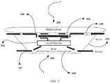
- FIG. 1 is a schematic structural diagram of a wireless charging device according to an embodiment of the present invention.
- the wireless charging device 100 includes a housing 101, an induction coil, a ferrite 102, a PCB 103, and a fan 104.
- the induction coil is attached to an upper surface of the ferrite 102, and the ferrite 102, the PCB 103, and the fan 104 are accommodated inside the housing 101.
- the housing 101 includes a first surface (an upper surface of the wireless charging device 100) and a second surface (a side surface of the wireless charging device 100), a protrusion 105 is disposed on the first surface, and the protrusion 105 is configured to: support a to-be-charged device (a mobile phone 200), and leave a gap between the to-be-charged device and the first surface when the to-be-charged device is installed on the wireless charging device.
- the ferrite 102 is disposed close to the first surface. At least one first air guiding opening 106 and at least one second air guiding opening 107 are disposed on the housing 101.
- the first air guiding opening 106, the fan 104, and the second air guiding opening 107 form an air duct that passes through the ferrite 102 and the PCB 103.
- the gap forms a part of the air duct, or the gap forms an auxiliary air duct of the air duct.
- the fan 104 is disposed between the ferrite 102 and the PCB 103.
- the first air guiding opening 106 is disposed on the first surface.
- the second air guiding opening 107 is disposed on the second surface. A first part of the gap, the first air guiding opening, the fan, and the second air guiding opening form the air duct.
- a second part of the gap forms the auxiliary air duct of the air duct.
- the fan is built in the wireless charging device, and the air duct is designed by using an internal structure, so that an airflow can pass through the to-be-charged device side and a device that generates heat and that is inside the charging device.
- the entire to-be-charged device is in a forced convection heat transfer scenario, so that a local hot-spot temperature of a rear cover of the to-be-charged device during wireless charging is reduced. Therefore, thermal performance of the entire device is balanced, a heat dissipation capability of the to-be-charged device is greatly improved, current-limiting charging time is delayed, and a wireless charging speed is improved.
- the first air guiding opening 106 is an air inlet
- the second air guiding opening 107 is an air outlet.
- the wireless charging device may use a forward heat dissipation mode, namely, a suction mode, or may use a reverse heat dissipation mode, namely, a blowing mode. Implementations are flexible and diverse.
- a suction effect of disposing the hole on the groove to serve as the first air guiding opening may be better when the foregoing suction mode is used.
- the groove is an annular groove.
- a hole is disposed in a position that is on a side surface of the annular groove and that is close to the ferrite, to form the first air guiding opening.
- the hole is disposed in the position that is on the side surface of the annular groove and that is close to the ferrite, to form the first air guiding opening, so that a wind direction of the air guiding opening can be close to a source of heat inside the wireless charging device, and in addition, a waterproof function can be implemented.
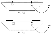
- FIG. 2(a) is a possible schematic structural diagram of the waterproof labyrinth.
- the hole for example, a hole 201 is disposed in the position that is on the side surface of the annular groove and that is close to the ferrite, to form the first air guiding opening.
- FIG. 2(b) is another possible schematic structural diagram of the waterproof labyrinth.
- a hole for example, a hole 202 is disposed in a position that is on a side surface of the annular groove and that is far away from the ferrite, to form the first air guiding opening.
- annular dust filter may be disposed above the annular groove.
- FIG. 3 is a top view of the wireless charging device according to this embodiment of the present invention. A possible structure of the annular dust filter may be learned from the top view.
- the annular dust filter 301 is dense holes in a ring shape on a front facet of the wireless charging device for air entering.
- the first air guiding opening 106 and the second air guiding opening 107 are disposed in flexible and diverse forms.
- a circle of openings may be disposed on the side surface of the annular groove to serve as the first air guiding opening 106, or only make openings in one or more places on the side surface of the annular groove to serve as the first air guiding opening 106.
- a circle of openings may be disposed in a lower position on the side surface of the wireless charging device to serve as the second air guiding opening 107, or only make openings in one or more places in a lower position on the side surface of the wireless charging device to serve as the second air guiding opening 107.
- a quantity of first air guiding openings 106 and a quantity of second air guiding openings 107 are not limited.
- the quantity of the first air guiding openings 106 is 4, and the quantity of the second air guiding openings 107 is 4; or the quantity of the first air guiding openings 106 is 4, and the quantity of the second air guiding openings 107 is 2; or the quantity of the first air guiding openings 106 is 1, and the quantity of the second air guiding openings 107 is 2; or the quantity of the first air guiding openings 106 is 1, and the quantity of the second air guiding openings 107 is 1.
- the fan is an axial flow fan or a centrifugal fan.
- FIG. 1 shows only a case in which the fan is the axial flow fan.
- the centrifugal fan may be selected.
- a type of the fan may be flexibly selected according to a structure of the air duct and the internal structure of the wireless charging device.
- a characteristic of the axial flow fan is a large air volume
- a characteristic of the centrifugal fan is a relatively small size and a high wind pressure.
- the protrusion 105 includes a plurality of spaced-apart slip-proof silicone convex hulls. According to this implementation, stability of placing the to-be-charged device can be ensured, and in addition, the gap between the to-be-charged device and the wireless charging device can be left.
- a height of the slip-proof silicone convex hull is 0.2 mm to 1 mm. According to this implementation, a charging effect can be considered while a good heat dissipation effect is ensured.
- the second air guiding opening 107 is disposed at a bottom of the side surface, to be far away from an area of a human hand, so that user experience is good.
- an inner ring on the front facet of the wireless charging device is sunk, the annular dust filter is disposed, the hole is disposed on the side surface of the sinking inner ring, air is extracted from an upper part of the axial flow fan, and air is exhausted from a lower part of the axial flow fan. Because the fan extracts the air, an external airflow enters through the hole of the side surface of the sinking inner ring, and passes through the rear cover of the mobile phone, the induction coil, the ferrite, and the PCB that generate heat. In this way, convection heat transfer between air and the devices that generate heat is enhanced, and finally, heated air is exhausted from the bottom of the side surface of the charging device, and is away from the area of the human hand. There is the gap between the mobile phone and the wireless charging device, and the gap is maintained by using a circle of spaced-apart slip-proof silicone convex hulls that are on the surface of the housing of the wireless charging device.
- the mobile phone When the mobile phone is wirelessly charged, the mobile phone is placed on the wireless charging device, and is supported by the slip-proof silicone convex hulls to keep the specific gap between the mobile phone and the wireless charging device.
- the hole is disposed on the side surface of the sinking inner ring on the front facet of the wireless charging device, and the waterproof labyrinth is disposed to implement a waterproof function.
- the entire charging device is in the suction mode, and the built-in axial flow fan extracts the air from the top and exhausts the air from the bottom. In this way, the airflow is extracted from outside, and is exhausted from the bottom of the side surface of the charging device after flowing through and cooling the rear cover of the mobile phone, and the ferrite and the coil that generate heat inside the charging device.
- a waterproof air duct architecture of the wireless charging device in the suction mode can reduce a temperature of the rear cover of the mobile phone to a largest extent while cooling the charging device, that is, simultaneously cools two sides, so that the local hot-spot temperature of the rear cover of the mobile phone is reduced. Therefore, usage experience of a user is ensured, and a charging speed is improved.
- FIG. 4 is a schematic structural diagram of another wireless charging device according to an embodiment of the present invention.
- the wireless charging device 400 includes a housing 401, an induction coil, a ferrite 402, a PCB 403, and a fan 404.
- the induction coil is attached to an upper surface of the ferrite 402, and the ferrite 402, the PCB 403, and the fan 404 are accommodated inside the housing 401.
- the housing 401 includes a first surface (an upper surface of the wireless charging device 400) and a second surface (a side surface of the wireless charging device 400), a protrusion 405 is disposed on the first surface, and the protrusion 405 is configured to: support a to-be-charged device (a mobile phone 410), and leave a gap between the to-be-charged device and the first surface when the to-be-charged device is installed on the wireless charging device.
- the ferrite 402 is disposed close to the first surface. At least one first air guiding opening 406 and at least one second air guiding opening 407 are disposed on the housing 401.
- the first air guiding opening 406, the fan 404, and the second air guiding opening 407 form an air duct that passes through the ferrite 402 and the PCB 403.
- the gap forms a part of the air duct, or the gap forms an auxiliary air duct of the air duct.
- the fan 404 is disposed between the ferrite 402 and the PCB 403.
- the wireless charging device 400 further includes a guide plate 408, and the guide plate 408 is disposed between the first air guiding opening 406 and the fan 404.
- the first air guiding opening 406, the fan 404, the second air guiding opening 407, and space surrounded by the guide plate 408 form the air duct.
- the gap forms the auxiliary air duct of the air duct.
- the air duct is established by using the guide plate, to lead an airflow to the to-be-charged device, so that forced convection heat transfer is directly performed on a part that is of the to-be-charged device and that generates heat heavily; in addition, the guide plate generates a jet effect, so that the to-be-charged device is cooled by air exhausted by the fan, and is further affected by a diversion disturbance formed due to a jet differential pressure.
- convection heat transfer of another part of the to-be-charged device is enhanced, so that the entire to-be-charged device is in a forced convection heat transfer scenario, and a local hot-spot temperature of the to-be-charged device during wireless charging is reduced. Therefore, thermal performance of the entire device is balanced, a heat dissipation capability of the to-be-charged device is greatly improved, current-limiting charging time is delayed, and a wireless charging speed is improved.
- the second air guiding opening is an air inlet
- the first air guiding opening is an air outlet.
- the guide plate generates the jet effect by using the first air guiding opening, so that the to-be-charged device is cooled by the air exhausted by the fan, and is further affected by the diversion disturbance formed due to the jet differential pressure. In this way, the convection heat transfer of the another part of the to-be-charged device is enhanced, so that the entire to-be-charged device is in the forced convection heat transfer scenario.
- the first air guiding opening 406 and the second air guiding opening 407 are disposed in flexible and diverse forms.
- a large opening may be disposed on an edge of the first surface to serve as the first air guiding opening 406, and the large opening further includes a plurality of small openings; or only make openings in one or more places on the first surface to serve as the first air guiding opening 406.
- a circle of openings may be disposed in a lower position on the side surface of the wireless charging device to serve as the second air guiding opening 407, or only make openings in one or more places in a lower position on the side surface of the wireless charging device to serve as the second air guiding opening 407.
- a quantity of first air guiding openings 406 and a quantity of second air guiding openings 407 are not limited.
- the quantity of the first air guiding openings 406 is 2, and the quantity of the second air guiding openings 407 is 4; or the quantity of the first air guiding openings 406 is 4, and the quantity of the second air guiding openings 407 is 4; or the quantity of the first air guiding openings 406 is 1, and the quantity of the second air guiding openings 407 is 4; or the quantity of the first air guiding openings 406 is 1, and the quantity of the second air guiding openings 407 is 1.
- a diameter of the guide plate gradually decreases in a direction from the fan to the first air guiding opening. According to this implementation, by using the gradually narrowed guide plate, an air speed can increase, so that the jet effect is more obvious, and a heat dissipation effect is better.
- an inclination angle between the guide plate and the first surface is 20° to 40°. According to this implementation, it can be met that air exhausted through the guide plate from the first air guiding opening is directed to the to-be-charged device, and in addition, the jet effect can be more obvious, and the heat dissipation effect can be better.
- the inclination angle between the guide plate and the first surface is related to a position of the first air guiding opening.
- the first air guiding opening may be disposed at an intersection of the first surface and the second surface, or on the edge of the first surface, or on an edge of the second surface.
- the position of the first air guiding opening may be slightly adjusted by a person skilled in the art according to an actual requirement, and is not limited to a position shown in FIG. 4 .
- the fan is a centrifugal fan.
- a wind pressure generated by the centrifugal fan is large, so that the jet effect can be more obvious, and the heat dissipation effect can be better.
- the protrusion 405 includes a plurality of spaced-apart slip-proof silicone convex hulls. According to this implementation, stability of placing the to-be-charged device can be ensured, and in addition, the gap between the to-be-charged device and the wireless charging device can be left.
- a height of the slip-proof silicone convex hull is 0.2 mm to 1 mm. According to this implementation, a charging effect can be considered while a good heat dissipation effect is ensured.
- the gap between the mobile phone and the wireless charging device is maintained by using a circle of spaced-apart slip-proof silicone convex hulls that are on the surface of the housing of the wireless charging device.
- the mobile phone When the mobile phone is wirelessly charged, the mobile phone is placed on the wireless charging device, and is supported by the slip-proof silicone convex hulls to keep a specific gap between the mobile phone and the wireless charging device.
- the air enters from a bottom of the wireless charging device and passes through the induction coil and the ferrite. Then, the air is extracted from the lower part of the centrifugal fan and is exhausted from a side of the centrifugal fan, and then, after being speed up by using the guide plate that is gradually narrowed in the upward slope direction, the air jets out from an upper edge of the wireless charging device to an upper part of a rear cover of the mobile phone (in other words, a position near the local hot spot during charging).
- diversion is formed due to an air differential pressure, and an airflow disturbance is formed at the middle and lower part of the mobile phone based on the diversion, so that convection heat transfer is enhanced.
- the air-cooled wireless charging device the temperature of the rear cover of the mobile phone is reduced to a largest extent while the temperature of the wireless charging device is reduced, so that the local hot-spot temperature of the rear cover is reduced. Therefore, user experience is ensured, and the charging speed is improved.
- the air may be extracted from both an upper part and the lower part of the centrifugal fan.
- a manner of extracting the air by the fan may be as follows: The lower part is blocked, and the air is extracted from only the upper part, so that the air duct that passes through the induction coil and the ferrite is formed to cool the induction coil and the ferrite that generate heat, and therefore, a temperature of the surface of the wireless charging device is reduced.
- FIG. 5 is a schematic structural diagram of still another wireless charging device according to an embodiment of the present invention.
- the wireless charging device 500 includes a housing 501, an induction coil, a ferrite 502, a PCB 503, and a fan 504.
- the induction coil is attached to an upper surface of the ferrite 502, and the ferrite 502, the PCB 503, and the fan 504 are accommodated inside the housing 501.
- the housing 501 includes a first surface (an upper surface of the wireless charging device 500) and a second surface (a side surface of the wireless charging device 500), a protrusion 505 is disposed on the first surface, and the protrusion 505 is configured to: support a to-be-charged device (a mobile phone 510), and leave a gap between the to-be-charged device and the first surface when the to-be-charged device is installed on the wireless charging device.
- the ferrite 502 is disposed close to the first surface. At least one first air guiding opening 506 and at least one second air guiding opening 507 are disposed on the housing 501.
- the first air guiding opening 506, the fan 504, and the second air guiding opening 507 form an air duct that passes through the ferrite 502 and the PCB 503.
- the gap forms a part of the air duct, or the gap forms an auxiliary air duct of the air duct.
- the fan 504 is disposed on a side that is of the PCB 503 and that is far away from the ferrite.
- the wireless charging device 500 further includes a guide plate 508, and the guide plate 508 is disposed between the first air guiding opening 506 and the PCB 503.
- the first air guiding opening 506, the fan 504, the second air guiding opening 507, and space surrounded by the guide plate 508 form the air duct.
- a third air guiding opening 509 is disposed on the first surface, and the third air guiding opening 509 leads to the space surrounded by the guide plate 508.
- the third air guiding opening 509 and the gap form a part of the air duct.
- the third air guiding opening 509 and the gap form an auxiliary air duct of the air duct.
- the air duct is established by using the guide plate, so that air passes through the PCB to dissipate heat of the PCB.
- the guide plate because the third air guiding opening is disposed on the first surface, and the third air guiding opening leads to the space surrounded by the guide plate, the guide plate generates a jet effect, and because of a diversion disturbance formed due to a jet differential pressure, an airflow passes through the gap between the to-be-charged device and the first surface to enter, through the third air guiding opening, the space surrounded by the guide plate. Therefore, convection heat transfer of the to-be-charged device is enhanced, so that the entire to-be-charged device is in a forced convection heat transfer scenario.
- the second air guiding opening and the third air guiding opening are air inlets, and the first air guiding opening is an air outlet.
- the airflow can pass through the to-be-charged device and a device that generates heat and that is inside the wireless charging device.
- the first air guiding opening 506, the second air guiding opening 507, and the third air guiding opening 509 are disposed in flexible and diverse forms.
- a circle of openings may be disposed on a side surface of an annular groove to serve as the third air guiding opening 509, or only make openings in one or more places on a side surface of an annular groove to serve as the third air guiding opening 509.
- a circle of openings may be disposed on the side surface of the wireless charging device to serve as the first air guiding opening 506, or only make openings in one or more places on the side surface of the wireless charging device to serve as the first air guiding opening 506.
- a circle of openings may be disposed on the side surface of the wireless charging device to serve as the second air guiding opening 507, or only make openings in one or more places on the side surface of the wireless charging device to serve as the second air guiding opening 507.
- a quantity of first air guiding openings 506, a quantity of second air guiding openings 507, and a quantity of third air guiding openings 509 are not limited.
- the quantity of the first air guiding openings 506 is 1, the quantity of the second air guiding openings 507 is 1, and the quantity of the third air guiding openings 509 is 1; or the quantity of the first air guiding openings 506 is 2, the quantity of the second air guiding openings 507 is 2, and the quantity of the third air guiding opening 509 is 4; or the quantity of the first air guiding openings 506 is 1, the quantity of the second air guiding openings 507 is 2, and the quantity of the third air guiding opening 509 is 4; or the quantity of the first air guiding openings 506 is 4, the quantity of the second air guiding openings 507 is 4, and the quantity of the third air guiding opening 509 is 4.
- a diameter of the guide plate gradually decreases in a direction from the PCB to the first air guiding opening. According to this implementation, by using the gradually narrowed guide plate, an air speed can increase, so that the jet effect is more obvious, and a heat dissipation effect is better.
- a groove on the first surface there is a groove on the first surface, and a hole is disposed on the groove to serve as the third air guiding opening.
- the hole is disposed on the groove to serve as the third air guiding opening, so that a diversion effect may be better.
- the groove is an annular groove.
- a hole is disposed in a position that is on a side surface of the annular groove and that is close to the ferrite, to form the third air guiding opening.
- the hole is disposed in the position that is on the side surface of the annular groove and that is close to the ferrite, to form the third air guiding opening, so that a wind direction of the air guiding opening can be close to a source of heat inside the wireless charging device, and in addition, a waterproof function may be implemented.
- a structure of the third air guiding opening refer to FIG. 2 and FIG. 3 . Details are not described herein again.
- the fan is an axial flow fan.
- the axial flow fan is used, so that an air volume is large, and heat dissipation is enhanced.
- the protrusion 505 includes a plurality of spaced-apart slip-proof silicone convex hulls. According to this implementation, stability of placing the to-be-charged device can be ensured, and in addition, the gap between the to-be-charged device and the wireless charging device can be left.
- a height of the slip-proof silicone convex hull is 0.2 mm to 1 mm. According to this implementation, a charging effect can be considered while a good heat dissipation effect is ensured.
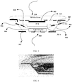
- FIG. 6 is a three-dimensional cross-sectional diagram of a wireless charging device according to an embodiment of the present invention.
- the wireless charging device and the wireless charging device shown in FIG. 5 may be a same wireless charging device.
- a guide plate is in positions numbered by 1 and 3
- a third air guiding opening is in a position numbered by 2.
- An airflow passes out from space between the guide plates 1 and 3. According to a jet principle, the airflow enters through the third air guiding opening 2, and the airflow passes through a gap between a mobile phone and the wireless charging device, so that a bidirectional heat dissipation effect of the mobile phone and the wireless charging device is achieved.
- a material selected for a housing of the wireless charging device may be acrylonitrile butadiene styrene (Acrylonitrile Butadiene Styrene, ABS) plastic, glass, and the like, and an appearance may be in a shape such as a cuboid, a cylinder, or a frustum of a cone.
- ABS acrylonitrile butadiene styrene
Landscapes
- Engineering & Computer Science (AREA)
- Microelectronics & Electronic Packaging (AREA)
- Power Engineering (AREA)
- Physics & Mathematics (AREA)
- Thermal Sciences (AREA)
- Computer Networks & Wireless Communication (AREA)
- Cooling Or The Like Of Electrical Apparatus (AREA)
- Charge And Discharge Circuits For Batteries Or The Like (AREA)
Abstract
Description
- The present invention relates to the charging field, and in particular, to a wireless charging device.
- With development of a charging technology of a mobile phone, wireless charging is becoming a more convenient charging trend. In a wireless charging technology, an induction coil is used to charge. Disadvantages of this charging manner are that electrical energy utilization is low and high heat is generated, resulting in a higher temperature of a housing of a mobile phone during charging. Consequently, usage experience of a user is seriously affected, and in addition, a wireless charging speed is slow.
- Generally, during wireless charging, the mobile phone is placed above a wireless charging device, and is closely placed on the wireless charging device, or there is only a small gap. By using the wireless charging device, an area of natural convection heat transfer between the mobile phone and air is reduced, and heat generated by the wireless charging device is transferred to the mobile phone, causing a worse heat dissipation environment of the mobile phone. If heat dissipation is not properly processed, a temperature of the mobile phone is excessively high, and consequently, consumer experience is greatly compromised. In addition, when the mobile phone is charged, current-limiting temperature control is usually set. When the housing reaches a specific temperature, a charging power is limited to reduce the temperature of the mobile phone. During charging, when the temperature of the mobile phone rises to a current-limiting temperature very fast, the charging power is greatly limited, and consequently, a charging speed is slowed down and a charging time is prolonged. This is inconsistent with a requirement of a consumer when a requirement for fast charging is increasingly strong, and the wireless charging is easily to be useless. During the wireless charging, it needs to be considered how to prolong current-limiting time of the charging, and even charge at rated power without current limiting, so as to improve the wireless charging speed. Heat has become one of the biggest bottlenecks that restrict the wireless charging speed. Therefore, it is especially important to reduce the temperature on the mobile phone side.
- For a heat dissipation design of an existing wireless charging device, there are three manners. A first manner is a pure natural heat dissipation manner, and in this manner, heat of a printed circuit board (Printed Circuit Board, PCB) and an induction coil is dissipated through natural convection with an external environment by using a heat dissipation hole on a side of the wireless charging device. In a second manner, a fan is built in the wireless charging device to perform heat dissipation on a ferrite and the induction coil, so that a temperature of a surface of the charging device is reduced, and user experience is improved. In a third manner, a hole is disposed on a front facet of the wireless charging device, and a built-in fan blows to a mobile phone side to reduce a temperature of the mobile phone.
- For the foregoing first natural heat dissipation manner, a heat dissipation capability is poor, and consequently the heat of the induction coil and the ferrite inside the wireless charging device is not effectively dissipated. In this case, the heat accumulates locally. As a result, the surface of the wireless charging device is hot, and heat dissipation of a rear cover of the mobile phone is deteriorated. The foregoing second manner in which the heat is dissipated by using the fan slightly improves on a basis of the first manner. To be specific, the temperature of the surface of the wireless charging device is reduced, however, there is a limitation that only a temperature of the wireless charging device is reduced, but the temperature of the mobile phone cannot be reduced. Current limiting of charging the mobile phone is mainly controlled based on a temperature of a housing of the mobile phone. If the temperature of the mobile phone cannot be reduced, charging power cannot be improved, and current-limiting time cannot be delayed, and therefore, charging time cannot be shortened. For the foregoing third manner, although the mobile phone can be cooled, heat of the wireless charging device cannot be effectively dissipated because the hole is disposed on the front facet of the wireless charging device. Because the wireless charging device is relatively close to the mobile phone, a heat dissipation effect on the mobile phone side is affected. In conclusion, in the prior art, there is no wireless charging device that can properly perform heat dissipation on a mobile phone.
- Embodiments of the present invention provide a wireless charging device, so that heat dissipation effect of a to-be-charged device such as a mobile phone is good.
- According to a first aspect, an embodiment of the present invention provides a wireless charging device. The wireless charging device includes a housing, an induction coil, a ferrite, a PCB, and a fan. The induction coil is attached to the ferrite, and the ferrite, the PCB, and the fan are accommodated inside the housing. The housing includes a first surface and a second surface, a protrusion is disposed on the first surface, and the protrusion is configured to: support a to-be-charged device, and leave a gap between the to-be-charged device and the first surface when the to-be-charged device is installed on the wireless charging device. The ferrite is disposed close to the first surface. At least one first air guiding opening and at least one second air guiding opening are disposed on the housing. When the fan runs, the first air guiding opening, the fan, and the second air guiding opening form an air duct that passes through the ferrite and the PCB. The gap forms a part of the air duct, or the gap forms an auxiliary air duct of the air duct.
- In this embodiment of the present invention, the fan is disposed inside the housing of the wireless charging device, so that the fan may drive air to flow to generate wind. The protrusion is disposed on the first surface of the wireless charging device, and the protrusion is configured to: support the to-be-charged device, and leave the gap between the to-be-charged device and the first surface when the to-be-charged device is installed on the wireless charging device, so that a channel is provided for the wind to flow through the to-be-charged device and the first surface. The ferrite is disposed close to the first surface, so that heat of the ferrite is dissipated when the wind flows through the first surface. The at least one first air guiding opening and the at least one second air guiding opening are disposed on the housing. When the fan runs, the first air guiding opening, the fan, and the second air guiding opening form the air duct that passes through the ferrite and the PCB, so that a source of heat inside the wireless charging device can be dissipated. The gap forms the part of the air duct, or the gap forms the auxiliary air duct of the air duct, so that heat of the to-be-charged device can also be dissipated.
- In a possible implementation, the fan is disposed between the ferrite and the PCB; the first air guiding opening is disposed on the first surface, and the second air guiding opening is disposed on the second surface; and a first part of the gap, the first air guiding opening, the fan, and the second air guiding opening form the air duct, and a second part of the gap forms the auxiliary air duct of the air duct. According to this implementation, the fan is built in the wireless charging device, and the air duct is designed by using an internal structure, so that an airflow can pass through the to-be-charged device side and a device that generates heat and that is inside the charging device. In this way, not only the charging device is cooled, but also the entire to-be-charged device is in a forced convection heat transfer scenario, so that a local hot-spot temperature of a rear cover of the to-be-charged device during wireless charging is reduced. Therefore, thermal performance of the entire device is balanced, a heat dissipation capability of the to-be-charged device is greatly improved, current-limiting charging time is delayed, and a wireless charging speed is improved.
- In a possible implementation, the first air guiding opening is an air inlet, and the second air guiding opening is an air outlet; or the second air guiding opening is an air inlet, and the first air guiding opening is an air outlet. According to this implementation, for the to-be-charged device, the wireless charging device may use a forward heat dissipation mode, namely, a suction mode, or may use a reverse heat dissipation mode, namely, a blowing mode. Implementations are flexible and diverse.
- In a possible implementation, there is a groove on the first surface, and a hole is disposed on the groove to serve as the first air guiding opening. According to this implementation, the hole is disposed on the groove to serve as the first air guiding opening, so that the suction mode is recommended.
- In a possible implementation, the groove is an annular groove, and a hole is disposed on a side surface of the annular groove to form the first air guiding opening. According to this implementation, the hole is disposed on the side surface of the annular groove, so that a waterproof function may be implemented.
- In a possible implementation, the fan is an axial flow fan or a centrifugal fan. According to this implementation, a type of the fan may be flexibly selected according to a structure of the air duct and an internal structure of the wireless charging device. For an axial flow fan and a centrifugal fan of a same size, a characteristic of the axial flow fan is a large air volume and a low wind pressure, a characteristic of the centrifugal fan is a small air volume and a high wind pressure, and the centrifugal fan may be made relatively small in thickness.
- In a possible implementation, the fan is disposed between the ferrite and the PCB; the wireless charging device further includes a guide plate, and the guide plate is disposed between the first air guiding opening and the fan; the first air guiding opening, the fan, the second air guiding opening, and space surrounded by the guide plate form the air duct; and the gap forms the auxiliary air duct of the air duct. According to this implementation, the air duct is established by using the guide plate, to lead an airflow to the to-be-charged device, so that forced convection heat transfer is directly performed on a part that is of the to-be-charged device and that generates heat heavily; in addition, the guide plate generates a jet effect, so that the to-be-charged device is cooled by air exhausted by the fan, and is affected by a diversion disturbance formed due to a jet differential pressure. In this way, convection heat transfer of another part of the to-be-charged device is enhanced, so that the entire to-be-charged device is in a forced convection heat transfer scenario, and a local hot-spot temperature of the to-be-charged device during wireless charging is reduced. Therefore, the thermal performance of the entire device is balanced, the heat dissipation capability of the to-be-charged device is greatly improved, the current-limiting charging time is delayed, and the wireless charging speed is improved.
- In a possible implementation, the second air guiding opening is an air inlet, and the first air guiding opening is an air outlet. According to this implementation, the guide plate generates the jet effect by using the first air guiding opening, so that the to-be-charged device is cooled by the air exhausted by the fan, and is further affected by the diversion disturbance formed due to the jet differential pressure. In this way, the convection heat transfer of the another part of the to-be-charged device is enhanced, so that the entire to-be-charged device is in the forced convection heat transfer scenario.
- In a possible implementation, a diameter of the guide plate gradually decreases in a direction from the fan to the first air guiding opening. According to this implementation, by using the gradually narrowed guide plate, an air speed can increase, so that the jet effect is more obvious, and a heat dissipation effect is better.
- In a possible implementation, an inclination angle between the guide plate and the first surface is 20° to 40°. According to this implementation, it can be met that air exhausted through the guide plate from the first air guiding opening is directed to the to-be-charged device, and in addition, the jet effect can be more obvious, and the heat dissipation effect can be better.
- In a possible implementation, the fan is a centrifugal fan. According to this implementation, a wind pressure generated by the centrifugal fan is large, so that the jet effect can be more obvious, and the heat dissipation effect can be better.
- In a possible implementation, the fan is disposed on a side that is of the PCB and that is far away from the ferrite; the wireless charging device further includes a guide plate, and the guide plate is disposed between the first air guiding opening and the PCB; the first air guiding opening, the fan, the second air guiding opening, and space surrounded by the guide plate form the air duct; a third air guiding opening is disposed on the first surface, and the third air guiding opening leads to the space surrounded by the guide plate; and the third air guiding opening and the gap form a part of the air duct; or the third air guiding opening and the gap form the auxiliary air duct of the air duct. According to this implementation, the air duct is established by using the guide plate, so that air passes through the PCB to dissipate heat of the PCB; and in addition, because the third air guiding opening is disposed on the first surface, and the third air guiding opening leads to the space surrounded by the guide plate, the guide plate generates a jet effect, and because of a diversion disturbance formed due to a jet differential pressure, an airflow passes through the gap between the to-be-charged device and the first surface to enter the space surrounded by the guide plate through the third air guiding opening. Therefore, convection heat transfer of the to-be-charged device is enhanced, so that the entire to-be-charged device is in a forced convection heat transfer scenario.
- In a possible implementation, the second air guiding opening and the third air guiding opening are air inlets, and the first air guiding opening is an air outlet. According to this implementation, the airflow can pass through the to-be-charged device and a device that generates heat and that is inside the wireless charging device.
- In a possible implementation, a diameter of the guide plate gradually decreases in a direction from the PCB to the first air guiding opening. According to this implementation, by using the gradually narrowed guide plate, an air speed can increase, so that the jet effect is more obvious, and a heat dissipation effect is better.
- In a possible implementation, there is a groove on the first surface, and a hole is disposed on the groove to serve as the third air guiding opening. According to this implementation, the hole is disposed on the groove to serve as the third air guiding opening, so that a diversion effect may be better.
- In a possible implementation, the groove is an annular groove. A hole is disposed in a position that is on a side surface of the annular groove and that is close to the ferrite, to form the third air guiding opening. According to this implementation, the hole is disposed in the position that is on the side surface of the annular groove and that is close to the ferrite, to form the third air guiding opening, so that a wind direction of the air guiding opening can be close to a source of heat inside the wireless charging device, and in addition, a waterproof function can be implemented.
- In a possible implementation, the fan is an axial flow fan. According to this implementation, the axial flow fan is used, so that an air volume is large, and heat dissipation is enhanced.
- In a possible implementation, the protrusion includes a plurality of spaced-apart slip-proof silicone convex hulls. According to this implementation, stability of placing the to-be-charged device can be ensured, and in addition, the gap between the to-be-charged device and the wireless charging device can be left.
- In a possible implementation, a height of the spaced-apart slip-proof silicone convex hull is 0.2 mm to 1 mm. According to this implementation, a charging effect can be considered while a good heat dissipation effect is ensured.
-
-
FIG. 1 is a schematic structural diagram of a wireless charging device according to an embodiment of the present invention; -
FIG. 2(a) is a possible schematic structural diagram of a waterproof labyrinth, andFIG. 2(b) is another possible structural diagram of the waterproof labyrinth; -
FIG. 3 is a top view of a wireless charging device according to an embodiment of the present invention; -
FIG. 4 is a schematic structural diagram of another wireless charging device according to an embodiment of the present invention; -
FIG. 5 is a schematic structural diagram of still another wireless charging device according to an embodiment of the present invention; and -
FIG. 6 is a three-dimensional cross-sectional diagram of a wireless charging device according to an embodiment of the present invention. - The embodiments of the present invention provide a wireless charging device. The wireless charging device includes a housing, an induction coil, a ferrite, a PCB, and a fan. The induction coil is attached to the ferrite, and the ferrite, the PCB, and the fan are accommodated inside the housing. The housing includes a first surface and a second surface, a protrusion is disposed on the first surface, and the protrusion is configured to: support a to-be-charged device, and leave a gap between the to-be-charged device and the first surface when the to-be-charged device is installed on the wireless charging device. The ferrite is disposed close to the first surface. At least one first air guiding opening and at least one second air guiding opening are disposed on the housing. When the fan runs, the first air guiding opening, the fan, and the second air guiding opening form an air duct that passes through the ferrite and the PCB. The gap forms a part of the air duct, or the gap forms an auxiliary air duct of the air duct.
- In the embodiments of the present invention, the fan is disposed inside the housing of the wireless charging device, so that the fan can drive air to flow to generate wind. The protrusion is disposed on the first surface of the wireless charging device, and the protrusion is configured to: support the to-be-charged device, and leave the gap between the to-be-charged device and the first surface when the to-be-charged device is installed on the wireless charging device, so that a channel is provided for the wind to flow through the to-be-charged device and the first surface. The ferrite is disposed close to the first surface, so that heat of the ferrite is dissipated when the wind flows through the first surface. The at least one first air guiding opening and the at least one second air guiding opening are disposed on the housing. When the fan runs, the first air guiding opening, the fan, and the second air guiding opening form the air duct that passes through the ferrite and the PCB, so that a source of heat inside the wireless charging device can be dissipated. The gap forms the part of the air duct, or the gap forms the auxiliary air duct of the air duct, so that heat of the to-be-charged device can also be dissipated.
- In the embodiments of the present invention, the air duct is designed inside the wireless charging device, so that a cooling airflow passes through a device (for example, the induction coil, the ferrite, and the PCB) that generates heat and that is inside the wireless charging device, and simultaneously passes through the to-be-charged device. Based on this inventive concept, a plurality of possible implementations may be used. The foregoing to-be-charged device may be a mobile phone, a PAD, a watch, a band, or the like. In the following embodiments of the present invention, the mobile phone is generally used as an example for description.
-
FIG. 1 is a schematic structural diagram of a wireless charging device according to an embodiment of the present invention. Thewireless charging device 100 includes ahousing 101, an induction coil, aferrite 102, aPCB 103, and afan 104. The induction coil is attached to an upper surface of theferrite 102, and theferrite 102, thePCB 103, and thefan 104 are accommodated inside thehousing 101. Thehousing 101 includes a first surface (an upper surface of the wireless charging device 100) and a second surface (a side surface of the wireless charging device 100), aprotrusion 105 is disposed on the first surface, and theprotrusion 105 is configured to: support a to-be-charged device (a mobile phone 200), and leave a gap between the to-be-charged device and the first surface when the to-be-charged device is installed on the wireless charging device. Theferrite 102 is disposed close to the first surface. At least one firstair guiding opening 106 and at least one secondair guiding opening 107 are disposed on thehousing 101. When thefan 104 runs, the firstair guiding opening 106, thefan 104, and the secondair guiding opening 107 form an air duct that passes through theferrite 102 and thePCB 103. The gap forms a part of the air duct, or the gap forms an auxiliary air duct of the air duct. Thefan 104 is disposed between theferrite 102 and thePCB 103. The firstair guiding opening 106 is disposed on the first surface. The secondair guiding opening 107 is disposed on the second surface. A first part of the gap, the first air guiding opening, the fan, and the second air guiding opening form the air duct. A second part of the gap forms the auxiliary air duct of the air duct. - In this embodiment of the present invention, the fan is built in the wireless charging device, and the air duct is designed by using an internal structure, so that an airflow can pass through the to-be-charged device side and a device that generates heat and that is inside the charging device. In this way, not only the charging device is cooled, but also the entire to-be-charged device is in a forced convection heat transfer scenario, so that a local hot-spot temperature of a rear cover of the to-be-charged device during wireless charging is reduced. Therefore, thermal performance of the entire device is balanced, a heat dissipation capability of the to-be-charged device is greatly improved, current-limiting charging time is delayed, and a wireless charging speed is improved.
- Referring to
FIG. 1 , the firstair guiding opening 106 is an air inlet, and the secondair guiding opening 107 is an air outlet. It may be understood that the same is applied to a contrary case, to be specific, the secondair guiding opening 107 is an air inlet, and the firstair guiding opening 106 is an air outlet. According to this implementation, for the to-be-charged device, the wireless charging device may use a forward heat dissipation mode, namely, a suction mode, or may use a reverse heat dissipation mode, namely, a blowing mode. Implementations are flexible and diverse. - In an example, there is a groove on the first surface, and a hole is disposed on the groove to serve as the first air guiding opening. According to this implementation, a suction effect of disposing the hole on the groove to serve as the first air guiding opening may be better when the foregoing suction mode is used.
- In an example, the groove is an annular groove. A hole is disposed in a position that is on a side surface of the annular groove and that is close to the ferrite, to form the first air guiding opening. According to this implementation, the hole is disposed in the position that is on the side surface of the annular groove and that is close to the ferrite, to form the first air guiding opening, so that a wind direction of the air guiding opening can be close to a source of heat inside the wireless charging device, and in addition, a waterproof function can be implemented.
- A waterproof structure of the first air guiding opening may be referred to as a waterproof labyrinth.
FIG. 2(a) is a possible schematic structural diagram of the waterproof labyrinth. To be specific, the hole (for example, a hole 201) is disposed in the position that is on the side surface of the annular groove and that is close to the ferrite, to form the first air guiding opening.FIG. 2(b) is another possible schematic structural diagram of the waterproof labyrinth. To be specific, a hole (for example, a hole 202) is disposed in a position that is on a side surface of the annular groove and that is far away from the ferrite, to form the first air guiding opening. - In an example, an annular dust filter may be disposed above the annular groove.
FIG. 3 is a top view of the wireless charging device according to this embodiment of the present invention. A possible structure of the annular dust filter may be learned from the top view. InFIG. 3 , theannular dust filter 301 is dense holes in a ring shape on a front facet of the wireless charging device for air entering. - In this embodiment of the present invention, the first
air guiding opening 106 and the secondair guiding opening 107 are disposed in flexible and diverse forms. For example, a circle of openings may be disposed on the side surface of the annular groove to serve as the firstair guiding opening 106, or only make openings in one or more places on the side surface of the annular groove to serve as the firstair guiding opening 106. A circle of openings may be disposed in a lower position on the side surface of the wireless charging device to serve as the secondair guiding opening 107, or only make openings in one or more places in a lower position on the side surface of the wireless charging device to serve as the secondair guiding opening 107. - In this embodiment of the present invention, a quantity of first
air guiding openings 106 and a quantity of secondair guiding openings 107 are not limited. For example, the quantity of the firstair guiding openings 106 is 4, and the quantity of the secondair guiding openings 107 is 4; or the quantity of the firstair guiding openings 106 is 4, and the quantity of the secondair guiding openings 107 is 2; or the quantity of the firstair guiding openings 106 is 1, and the quantity of the secondair guiding openings 107 is 2; or the quantity of the firstair guiding openings 106 is 1, and the quantity of the secondair guiding openings 107 is 1. - In an example, the fan is an axial flow fan or a centrifugal fan.
FIG. 1 shows only a case in which the fan is the axial flow fan. In practice, the centrifugal fan may be selected. According to this implementation, a type of the fan may be flexibly selected according to a structure of the air duct and the internal structure of the wireless charging device. A characteristic of the axial flow fan is a large air volume, and a characteristic of the centrifugal fan is a relatively small size and a high wind pressure. - In an example, the
protrusion 105 includes a plurality of spaced-apart slip-proof silicone convex hulls. According to this implementation, stability of placing the to-be-charged device can be ensured, and in addition, the gap between the to-be-charged device and the wireless charging device can be left. - In an example, a height of the slip-proof silicone convex hull is 0.2 mm to 1 mm. According to this implementation, a charging effect can be considered while a good heat dissipation effect is ensured.
- In addition, in
FIG. 1 , the secondair guiding opening 107 is disposed at a bottom of the side surface, to be far away from an area of a human hand, so that user experience is good. - As shown in
FIG. 1 , an inner ring on the front facet of the wireless charging device is sunk, the annular dust filter is disposed, the hole is disposed on the side surface of the sinking inner ring, air is extracted from an upper part of the axial flow fan, and air is exhausted from a lower part of the axial flow fan. Because the fan extracts the air, an external airflow enters through the hole of the side surface of the sinking inner ring, and passes through the rear cover of the mobile phone, the induction coil, the ferrite, and the PCB that generate heat. In this way, convection heat transfer between air and the devices that generate heat is enhanced, and finally, heated air is exhausted from the bottom of the side surface of the charging device, and is away from the area of the human hand. There is the gap between the mobile phone and the wireless charging device, and the gap is maintained by using a circle of spaced-apart slip-proof silicone convex hulls that are on the surface of the housing of the wireless charging device. - When the mobile phone is wirelessly charged, the mobile phone is placed on the wireless charging device, and is supported by the slip-proof silicone convex hulls to keep the specific gap between the mobile phone and the wireless charging device. The hole is disposed on the side surface of the sinking inner ring on the front facet of the wireless charging device, and the waterproof labyrinth is disposed to implement a waterproof function. The entire charging device is in the suction mode, and the built-in axial flow fan extracts the air from the top and exhausts the air from the bottom. In this way, the airflow is extracted from outside, and is exhausted from the bottom of the side surface of the charging device after flowing through and cooling the rear cover of the mobile phone, and the ferrite and the coil that generate heat inside the charging device. A waterproof air duct architecture of the wireless charging device in the suction mode can reduce a temperature of the rear cover of the mobile phone to a largest extent while cooling the charging device, that is, simultaneously cools two sides, so that the local hot-spot temperature of the rear cover of the mobile phone is reduced. Therefore, usage experience of a user is ensured, and a charging speed is improved.
- It may be understood that, to ensure the good heat dissipation effect, smooth of the entire air duct needs to be ensured, so as to reduce air resistance as much as possible.
-
FIG. 4 is a schematic structural diagram of another wireless charging device according to an embodiment of the present invention. Thewireless charging device 400 includes ahousing 401, an induction coil, aferrite 402, aPCB 403, and afan 404. The induction coil is attached to an upper surface of theferrite 402, and theferrite 402, thePCB 403, and thefan 404 are accommodated inside thehousing 401. Thehousing 401 includes a first surface (an upper surface of the wireless charging device 400) and a second surface (a side surface of the wireless charging device 400), aprotrusion 405 is disposed on the first surface, and theprotrusion 405 is configured to: support a to-be-charged device (a mobile phone 410), and leave a gap between the to-be-charged device and the first surface when the to-be-charged device is installed on the wireless charging device. Theferrite 402 is disposed close to the first surface. At least one firstair guiding opening 406 and at least one secondair guiding opening 407 are disposed on thehousing 401. When thefan 404 runs, the firstair guiding opening 406, thefan 404, and the secondair guiding opening 407 form an air duct that passes through theferrite 402 and thePCB 403. The gap forms a part of the air duct, or the gap forms an auxiliary air duct of the air duct. Thefan 404 is disposed between theferrite 402 and thePCB 403. Thewireless charging device 400 further includes aguide plate 408, and theguide plate 408 is disposed between the firstair guiding opening 406 and thefan 404. The firstair guiding opening 406, thefan 404, the secondair guiding opening 407, and space surrounded by theguide plate 408 form the air duct. The gap forms the auxiliary air duct of the air duct. - In this embodiment of the present invention, the air duct is established by using the guide plate, to lead an airflow to the to-be-charged device, so that forced convection heat transfer is directly performed on a part that is of the to-be-charged device and that generates heat heavily; in addition, the guide plate generates a jet effect, so that the to-be-charged device is cooled by air exhausted by the fan, and is further affected by a diversion disturbance formed due to a jet differential pressure. In this way, convection heat transfer of another part of the to-be-charged device is enhanced, so that the entire to-be-charged device is in a forced convection heat transfer scenario, and a local hot-spot temperature of the to-be-charged device during wireless charging is reduced. Therefore, thermal performance of the entire device is balanced, a heat dissipation capability of the to-be-charged device is greatly improved, current-limiting charging time is delayed, and a wireless charging speed is improved.
- In an example, the second air guiding opening is an air inlet, and the first air guiding opening is an air outlet. According to this implementation, the guide plate generates the jet effect by using the first air guiding opening, so that the to-be-charged device is cooled by the air exhausted by the fan, and is further affected by the diversion disturbance formed due to the jet differential pressure. In this way, the convection heat transfer of the another part of the to-be-charged device is enhanced, so that the entire to-be-charged device is in the forced convection heat transfer scenario.
- In this embodiment of the present invention, the first
air guiding opening 406 and the secondair guiding opening 407 are disposed in flexible and diverse forms. For example, a large opening may be disposed on an edge of the first surface to serve as the firstair guiding opening 406, and the large opening further includes a plurality of small openings; or only make openings in one or more places on the first surface to serve as the firstair guiding opening 406. A circle of openings may be disposed in a lower position on the side surface of the wireless charging device to serve as the secondair guiding opening 407, or only make openings in one or more places in a lower position on the side surface of the wireless charging device to serve as the secondair guiding opening 407. - In this embodiment of the present invention, a quantity of first
air guiding openings 406 and a quantity of secondair guiding openings 407 are not limited. For example, the quantity of the firstair guiding openings 406 is 2, and the quantity of the secondair guiding openings 407 is 4; or the quantity of the firstair guiding openings 406 is 4, and the quantity of the secondair guiding openings 407 is 4; or the quantity of the firstair guiding openings 406 is 1, and the quantity of the secondair guiding openings 407 is 4; or the quantity of the firstair guiding openings 406 is 1, and the quantity of the secondair guiding openings 407 is 1. - In an example, a diameter of the guide plate gradually decreases in a direction from the fan to the first air guiding opening. According to this implementation, by using the gradually narrowed guide plate, an air speed can increase, so that the jet effect is more obvious, and a heat dissipation effect is better.
- In an example, an inclination angle between the guide plate and the first surface is 20° to 40°. According to this implementation, it can be met that air exhausted through the guide plate from the first air guiding opening is directed to the to-be-charged device, and in addition, the jet effect can be more obvious, and the heat dissipation effect can be better.
- It may be understood that the inclination angle between the guide plate and the first surface is related to a position of the first air guiding opening. The first air guiding opening may be disposed at an intersection of the first surface and the second surface, or on the edge of the first surface, or on an edge of the second surface. The position of the first air guiding opening may be slightly adjusted by a person skilled in the art according to an actual requirement, and is not limited to a position shown in
FIG. 4 . - In an example, the fan is a centrifugal fan. According to this implementation, a wind pressure generated by the centrifugal fan is large, so that the jet effect can be more obvious, and the heat dissipation effect can be better.
- In an example, the
protrusion 405 includes a plurality of spaced-apart slip-proof silicone convex hulls. According to this implementation, stability of placing the to-be-charged device can be ensured, and in addition, the gap between the to-be-charged device and the wireless charging device can be left. - In an example, a height of the slip-proof silicone convex hull is 0.2 mm to 1 mm. According to this implementation, a charging effect can be considered while a good heat dissipation effect is ensured.
- As shown in
FIG. 4 , air enters through a hole disposed on a bottom of the side surface of the wireless charging device, and then, the air is extracted from only a lower part of the centrifugal fan, to passes through the induction coil and the ferrite that generate heat, so that air disturbance is enhanced, and convection heat transfer between the air and the devices that generate heat is enhanced; and the air exhausted by the fan is guided by the guide plate that is gradually narrowed in an upward slope direction, and a higher degree of narrowing the guide plate indicates a higher speed of exhausting the air and a better diversion effect of a lower and medium part of the mobile phone. There is the gap between the mobile phone and the wireless charging device, and the gap is maintained by using a circle of spaced-apart slip-proof silicone convex hulls that are on the surface of the housing of the wireless charging device. - When the mobile phone is wirelessly charged, the mobile phone is placed on the wireless charging device, and is supported by the slip-proof silicone convex hulls to keep a specific gap between the mobile phone and the wireless charging device. The air enters from a bottom of the wireless charging device and passes through the induction coil and the ferrite. Then, the air is extracted from the lower part of the centrifugal fan and is exhausted from a side of the centrifugal fan, and then, after being speed up by using the guide plate that is gradually narrowed in the upward slope direction, the air jets out from an upper edge of the wireless charging device to an upper part of a rear cover of the mobile phone (in other words, a position near the local hot spot during charging). According to a jet principle, diversion is formed due to an air differential pressure, and an airflow disturbance is formed at the middle and lower part of the mobile phone based on the diversion, so that convection heat transfer is enhanced. By using the air-cooled wireless charging device, the temperature of the rear cover of the mobile phone is reduced to a largest extent while the temperature of the wireless charging device is reduced, so that the local hot-spot temperature of the rear cover is reduced. Therefore, user experience is ensured, and the charging speed is improved.
- It may be understood that the air may be extracted from both an upper part and the lower part of the centrifugal fan. In an example, a manner of extracting the air by the fan may be as follows: The lower part is blocked, and the air is extracted from only the upper part, so that the air duct that passes through the induction coil and the ferrite is formed to cool the induction coil and the ferrite that generate heat, and therefore, a temperature of the surface of the wireless charging device is reduced.
-
FIG. 5 is a schematic structural diagram of still another wireless charging device according to an embodiment of the present invention. Thewireless charging device 500 includes ahousing 501, an induction coil, aferrite 502, aPCB 503, and afan 504. The induction coil is attached to an upper surface of theferrite 502, and theferrite 502, thePCB 503, and thefan 504 are accommodated inside thehousing 501. Thehousing 501 includes a first surface (an upper surface of the wireless charging device 500) and a second surface (a side surface of the wireless charging device 500), aprotrusion 505 is disposed on the first surface, and theprotrusion 505 is configured to: support a to-be-charged device (a mobile phone 510), and leave a gap between the to-be-charged device and the first surface when the to-be-charged device is installed on the wireless charging device. Theferrite 502 is disposed close to the first surface. At least one firstair guiding opening 506 and at least one secondair guiding opening 507 are disposed on thehousing 501. When thefan 504 runs, the firstair guiding opening 506, thefan 504, and the secondair guiding opening 507 form an air duct that passes through theferrite 502 and thePCB 503. The gap forms a part of the air duct, or the gap forms an auxiliary air duct of the air duct. Thefan 504 is disposed on a side that is of thePCB 503 and that is far away from the ferrite. Thewireless charging device 500 further includes aguide plate 508, and theguide plate 508 is disposed between the firstair guiding opening 506 and thePCB 503. The firstair guiding opening 506, thefan 504, the secondair guiding opening 507, and space surrounded by theguide plate 508 form the air duct. A thirdair guiding opening 509 is disposed on the first surface, and the thirdair guiding opening 509 leads to the space surrounded by theguide plate 508. The thirdair guiding opening 509 and the gap form a part of the air duct. Alternatively, the thirdair guiding opening 509 and the gap form an auxiliary air duct of the air duct. - In this embodiment of the present invention, the air duct is established by using the guide plate, so that air passes through the PCB to dissipate heat of the PCB. In addition, because the third air guiding opening is disposed on the first surface, and the third air guiding opening leads to the space surrounded by the guide plate, the guide plate generates a jet effect, and because of a diversion disturbance formed due to a jet differential pressure, an airflow passes through the gap between the to-be-charged device and the first surface to enter, through the third air guiding opening, the space surrounded by the guide plate. Therefore, convection heat transfer of the to-be-charged device is enhanced, so that the entire to-be-charged device is in a forced convection heat transfer scenario.
- In an example, the second air guiding opening and the third air guiding opening are air inlets, and the first air guiding opening is an air outlet. According to this implementation, the airflow can pass through the to-be-charged device and a device that generates heat and that is inside the wireless charging device.
- In this embodiment of the present invention, the first
air guiding opening 506, the secondair guiding opening 507, and the thirdair guiding opening 509 are disposed in flexible and diverse forms. For example, a circle of openings may be disposed on a side surface of an annular groove to serve as the thirdair guiding opening 509, or only make openings in one or more places on a side surface of an annular groove to serve as the thirdair guiding opening 509. A circle of openings may be disposed on the side surface of the wireless charging device to serve as the firstair guiding opening 506, or only make openings in one or more places on the side surface of the wireless charging device to serve as the firstair guiding opening 506. A circle of openings may be disposed on the side surface of the wireless charging device to serve as the secondair guiding opening 507, or only make openings in one or more places on the side surface of the wireless charging device to serve as the secondair guiding opening 507. - In this embodiment of the present invention, a quantity of first
air guiding openings 506, a quantity of secondair guiding openings 507, and a quantity of thirdair guiding openings 509 are not limited. For example, the quantity of the firstair guiding openings 506 is 1, the quantity of the secondair guiding openings 507 is 1, and the quantity of the thirdair guiding openings 509 is 1; or the quantity of the firstair guiding openings 506 is 2, the quantity of the secondair guiding openings 507 is 2, and the quantity of the thirdair guiding opening 509 is 4; or the quantity of the firstair guiding openings 506 is 1, the quantity of the secondair guiding openings 507 is 2, and the quantity of the thirdair guiding opening 509 is 4; or the quantity of the firstair guiding openings 506 is 4, the quantity of the secondair guiding openings 507 is 4, and the quantity of the thirdair guiding opening 509 is 4. - In an example, a diameter of the guide plate gradually decreases in a direction from the PCB to the first air guiding opening. According to this implementation, by using the gradually narrowed guide plate, an air speed can increase, so that the jet effect is more obvious, and a heat dissipation effect is better.
- In an example, there is a groove on the first surface, and a hole is disposed on the groove to serve as the third air guiding opening. According to this implementation, the hole is disposed on the groove to serve as the third air guiding opening, so that a diversion effect may be better.
- In an example, the groove is an annular groove. A hole is disposed in a position that is on a side surface of the annular groove and that is close to the ferrite, to form the third air guiding opening. According to this implementation, the hole is disposed in the position that is on the side surface of the annular groove and that is close to the ferrite, to form the third air guiding opening, so that a wind direction of the air guiding opening can be close to a source of heat inside the wireless charging device, and in addition, a waterproof function may be implemented. For a structure of the third air guiding opening, refer to
FIG. 2 andFIG. 3 . Details are not described herein again. - In an example, the fan is an axial flow fan. According to this implementation, the axial flow fan is used, so that an air volume is large, and heat dissipation is enhanced.
- In an example, the
protrusion 505 includes a plurality of spaced-apart slip-proof silicone convex hulls. According to this implementation, stability of placing the to-be-charged device can be ensured, and in addition, the gap between the to-be-charged device and the wireless charging device can be left. - In an example, a height of the slip-proof silicone convex hull is 0.2 mm to 1 mm. According to this implementation, a charging effect can be considered while a good heat dissipation effect is ensured.
-
FIG. 6 is a three-dimensional cross-sectional diagram of a wireless charging device according to an embodiment of the present invention. The wireless charging device and the wireless charging device shown inFIG. 5 may be a same wireless charging device. As shown inFIG. 6 , a guide plate is in positions numbered by ① and ③, and a third air guiding opening is in a position numbered by ②. An airflow passes out from space between the guide plates ① and ③. According to a jet principle, the airflow enters through the third air guiding opening ②, and the airflow passes through a gap between a mobile phone and the wireless charging device, so that a bidirectional heat dissipation effect of the mobile phone and the wireless charging device is achieved. - In this embodiment of the present invention, a material selected for a housing of the wireless charging device may be acrylonitrile butadiene styrene (Acrylonitrile Butadiene Styrene, ABS) plastic, glass, and the like, and an appearance may be in a shape such as a cuboid, a cylinder, or a frustum of a cone.
- The foregoing descriptions are merely example implementations of the present invention, but are not intended to limit the protection scope of the present invention. Any variation or replacement readily figured out by a person skilled in the art within the technical scope disclosed in the present invention shall fall within the protection scope of the present invention. Therefore, the protection scope of the present invention shall be subject to the protection scope of the claims.
Claims (19)
- A wireless charging device, wherein the wireless charging device comprises a housing, an induction coil, a ferrite, a printed circuit board (PCB), and a fan;
the induction coil is attached to the ferrite, and the ferrite, the PCB, and the fan are accommodated inside the housing; the housing comprises a first surface and a second surface, a protrusion is disposed on the first surface, and the protrusion is configured to: support a to-be-charged device, and leave a gap between the to-be-charged device and the first surface when the to-be-charged device is installed on the wireless charging device; the ferrite is disposed close to the first surface;
at least one first air guiding opening and at least one second air guiding opening are disposed on the housing;
when the fan runs, the first air guiding opening, the fan, and the second air guiding opening form an air duct that passes through the ferrite and the PCB; and
the gap forms a part of the air duct, or the gap forms an auxiliary air duct of the air duct. - The wireless charging device according to claim 1, wherein the fan is disposed between the ferrite and the PCB; the first air guiding opening is disposed on the first surface, and the second air guiding opening is disposed on the second surface; and a first part of the gap, the first air guiding opening, the fan, and the second air guiding opening form the air duct, and a second part of the gap forms the auxiliary air duct of the air duct.
- The wireless charging device according to claim 2, wherein the first air guiding opening is an air inlet, and the second air guiding opening is an air outlet; or the second air guiding opening is an air inlet, and the first air guiding opening is an air outlet.
- The wireless charging device according to claim 2 or 3, wherein there is a groove on the first surface, and a hole is disposed on the groove to serve as the first air guiding opening.
- The wireless charging device according to claim 4, wherein the groove is an annular groove; and a hole is disposed on a side surface of the annular groove to form the first air guiding opening.
- The wireless charging device according to any one of claims 2 to 5, wherein the fan is an axial flow fan or a centrifugal fan.
- The wireless charging device according to claim 1, wherein the fan is disposed between the ferrite and the PCB; the wireless charging device further comprises a guide plate, and the guide plate is disposed between the first air guiding opening and the fan; the first air guiding opening, the fan, the second air guiding opening, and space surrounded by the guide plate form the air duct; and the gap forms the auxiliary air duct of the air duct.
- The wireless charging device according to claim 7, wherein the second air guiding opening is an air inlet, and the first air guiding opening is an air outlet.
- The wireless charging device according to claim 7 or 8, wherein a diameter of the guide plate gradually decreases in a direction from the fan to the first air guiding opening.
- The wireless charging device according to any one of claims 7 to 9, wherein an inclination angle between the guide plate and the first surface is 20° to 40°.
- The wireless charging device according to any one of claims 7 to 10, wherein the fan is a centrifugal fan.
- The wireless charging device according to claim 1, wherein the fan is disposed on a side that is of the PCB and that is far away from the ferrite; the wireless charging device further comprises a guide plate, and the guide plate is disposed between the first air guiding opening and the PCB; the first air guiding opening, the fan, the second air guiding opening, and space surrounded by the guide plate form the air duct; a third air guiding opening is disposed on the first surface, and the third air guiding opening leads to the space surrounded by the guide plate; and the third air guiding opening and the gap form a part of the air duct; or the third air guiding opening and the gap form the auxiliary air duct of the air duct.
- The wireless charging device according to claim 12, wherein the second air guiding opening and the third air guiding opening are air inlets, and the first air guiding opening is an air outlet.
- The wireless charging device according to claim 12 or 13, wherein a diameter of the guide plate gradually decreases in a direction from the PCB to the first air guiding opening.
- The wireless charging device according to any one of claims 12 to 14, wherein there is a groove on the first surface, and a hole is disposed on the groove to serve as the third air guiding opening.
- The wireless charging device according to claim 15, wherein the groove is an annular groove; and a hole is disposed in a position that is on a side surface of the annular groove and that is close to the ferrite, to form the third air guiding opening.
- The wireless charging device according to any one of claims 12 to 16, wherein the fan is an axial flow fan.
- The wireless charging device according to any one of claims 1 to 17, wherein the protrusion comprises a plurality of spaced-apart slip-proof silicone convex hulls.
- The wireless charging device according to claim 18, wherein a height of the slip-proof silicone convex hull is 0.2 mm to 1 mm.
Priority Applications (1)
| Application Number | Priority Date | Filing Date | Title |
|---|---|---|---|
| EP22206095.6A EP4195895B1 (en) | 2017-10-30 | 2018-10-27 | Wireless charging device |
Applications Claiming Priority (2)
| Application Number | Priority Date | Filing Date | Title |
|---|---|---|---|
| CN201711035158.2A CN109729689B (en) | 2017-10-30 | 2017-10-30 | Wireless charging equipment |
| PCT/CN2018/112256 WO2019085839A1 (en) | 2017-10-30 | 2018-10-27 | Wireless charging device |
Related Child Applications (2)
| Application Number | Title | Priority Date | Filing Date |
|---|---|---|---|
| EP22206095.6A Division EP4195895B1 (en) | 2017-10-30 | 2018-10-27 | Wireless charging device |
| EP22206095.6A Division-Into EP4195895B1 (en) | 2017-10-30 | 2018-10-27 | Wireless charging device |
Publications (3)
| Publication Number | Publication Date |
|---|---|
| EP3694301A1 true EP3694301A1 (en) | 2020-08-12 |
| EP3694301A4 EP3694301A4 (en) | 2020-12-16 |
| EP3694301B1 EP3694301B1 (en) | 2023-01-11 |
Family
ID=66292305
Family Applications (2)
| Application Number | Title | Priority Date | Filing Date |
|---|---|---|---|
| EP22206095.6A Active EP4195895B1 (en) | 2017-10-30 | 2018-10-27 | Wireless charging device |
| EP18873394.3A Active EP3694301B1 (en) | 2017-10-30 | 2018-10-27 | Wireless charging device |
Family Applications Before (1)
| Application Number | Title | Priority Date | Filing Date |
|---|---|---|---|
| EP22206095.6A Active EP4195895B1 (en) | 2017-10-30 | 2018-10-27 | Wireless charging device |
Country Status (4)
| Country | Link |
|---|---|
| US (2) | US11419238B2 (en) |
| EP (2) | EP4195895B1 (en) |
| CN (2) | CN112054570B (en) |
| WO (1) | WO2019085839A1 (en) |
Cited By (1)
| Publication number | Priority date | Publication date | Assignee | Title |
|---|---|---|---|---|
| EP3852224A1 (en) * | 2020-01-14 | 2021-07-21 | Guangdong Oppo Mobile Telecommunications Corp., Ltd. | Wireless charger |
Families Citing this family (30)
| Publication number | Priority date | Publication date | Assignee | Title |
|---|---|---|---|---|
| KR101891600B1 (en) * | 2017-02-03 | 2018-08-24 | 엘지전자 주식회사 | Wireless charger for mobile terminal in vehicle and vehicle |
| CN112054570B (en) | 2017-10-30 | 2022-05-31 | 华为终端有限公司 | Wireless charging equipment |
| DE202017107183U1 (en) * | 2017-11-27 | 2017-12-07 | Elektrosil Systeme Der Elektronik Gmbh | Charger for wireless charging of a mobile terminal |
| US11476706B2 (en) * | 2019-08-16 | 2022-10-18 | Aptiv Technologies Limited | Wireless device charger with cooling device |
| EP4029104B1 (en) * | 2019-09-10 | 2025-06-25 | Valeo Interior Controls (Shenzhen) Co., Ltd. | Wireless charging transmitter and wireless charging system |
| EP3798745B1 (en) * | 2019-09-30 | 2022-07-13 | ETA SA Manufacture Horlogère Suisse | Watch case back with electronic device for wireless charging of a power source |
| US12046938B2 (en) * | 2019-10-23 | 2024-07-23 | Amphenol Tecvox, LLC | Vehicle battery charging apparatus |
| CN211480950U (en) * | 2019-12-02 | 2020-09-11 | Oppo广东移动通信有限公司 | wireless charging device |
| CN110880803B (en) | 2019-12-17 | 2022-02-15 | 台达电子企业管理(上海)有限公司 | wireless charging device |
| CN113036829B (en) | 2019-12-25 | 2024-12-27 | Oppo广东移动通信有限公司 | Wireless charging equipment |
| US11262819B2 (en) * | 2020-01-09 | 2022-03-01 | Htc Corporation | Electronic device |
| CN113193608B (en) * | 2020-01-14 | 2025-02-25 | Oppo广东移动通信有限公司 | Wireless charging equipment |
| WO2021143467A1 (en) * | 2020-01-14 | 2021-07-22 | Oppo广东移动通信有限公司 | Wireless charging device |
| CN113555914A (en) * | 2020-04-24 | 2021-10-26 | 北京小米移动软件有限公司 | Wireless charger |
| US11601015B2 (en) * | 2021-01-28 | 2023-03-07 | Cyntec Co., Ltd. | Wireless charger |
| CN113036853B (en) * | 2021-03-12 | 2022-08-16 | 合肥有感科技有限责任公司 | Wireless quick charging device, circuit structure thereof and charging and heat dissipation method |
| EP4075458A1 (en) * | 2021-04-16 | 2022-10-19 | Aptiv Technologies Limited | Air-cooled wireless power transmission system |
| US20220377947A1 (en) * | 2021-05-16 | 2022-11-24 | Aira, Inc. | Active cooling in a multi-device wireless charger |
| US20220399763A1 (en) * | 2021-06-10 | 2022-12-15 | Cyntec Co., Ltd. | Wireless Charger |
| CN115693822A (en) * | 2021-07-30 | 2023-02-03 | 北京小米移动软件有限公司 | Electronic equipment, electronic equipment control method and device |
| US12556035B2 (en) * | 2021-09-02 | 2026-02-17 | Molex, Llc | Wireless charger with venting system |
| CN113726027B (en) | 2021-09-03 | 2025-02-14 | 台达电子企业管理(上海)有限公司 | Wireless charging device |
| CN118842142A (en) * | 2021-09-13 | 2024-10-25 | Oppo广东移动通信有限公司 | Wireless charging seat and heat dissipation seat thereof and method for charging by using wireless charging seat |
| US11758686B1 (en) * | 2022-04-25 | 2023-09-12 | Dell Products L.P. | Induction heater-integrated air mover |
| CN114784987A (en) * | 2022-05-31 | 2022-07-22 | 重庆长安汽车股份有限公司 | Wireless heat abstractor and vehicle that charges |
| TWI826064B (en) * | 2022-08-01 | 2023-12-11 | 英業達股份有限公司 | Wireless charging device |
| TWI830370B (en) * | 2022-09-12 | 2024-01-21 | 致伸科技股份有限公司 | Wireless charging device |
| CN117955192A (en) * | 2022-10-31 | 2024-04-30 | 荣耀终端有限公司 | Wireless charging stand and wireless charging system |
| CN115622206B (en) * | 2022-12-19 | 2023-03-10 | 龙旗电子(惠州)有限公司 | On-vehicle wireless charger with dustproof function |
| CN119093609A (en) * | 2023-06-06 | 2024-12-06 | 英业达科技有限公司 | Wireless charging device |
Family Cites Families (37)
| Publication number | Priority date | Publication date | Assignee | Title |
|---|---|---|---|---|
| JPH11238638A (en) * | 1998-02-23 | 1999-08-31 | Toyota Autom Loom Works Ltd | Non-contact type charging device |
| US7868585B2 (en) * | 2006-10-03 | 2011-01-11 | Visteon Global Technologies, Inc. | Wireless charging device |
| WO2010026805A1 (en) * | 2008-09-03 | 2010-03-11 | 株式会社村田製作所 | Wireless power transmission device |
| CN202424237U (en) * | 2011-12-30 | 2012-09-05 | 深圳市沈氏彤创航天模型有限公司 | Internal heat radiation structure of charger |
| US9451723B2 (en) * | 2012-07-06 | 2016-09-20 | Gentherm Incorporated | System and method for thermoelectrically cooling inductive charging assemblies |
| KR101919162B1 (en) | 2012-11-21 | 2018-11-15 | 엘지전자 주식회사 | Apparatus and method for wireless charging mobile terminal |
| CN203434660U (en) * | 2013-07-24 | 2014-02-12 | 上海锐灵电子科技有限公司 | Wireless charging device of portable device |
| CN203574404U (en) | 2013-10-24 | 2014-04-30 | 杨庆春 | Wireless charging transmitter |
| CN103997083A (en) | 2014-05-06 | 2014-08-20 | 昆山佑翔电子科技有限公司 | Wireless charger with great heat dissipation effect |
| CN204012835U (en) * | 2014-07-23 | 2014-12-10 | 东莞市奇立电源有限公司 | A kind of electric car charger of wind trunk heat radiation |
| CN204144989U (en) * | 2014-08-26 | 2015-02-04 | 和硕联合科技股份有限公司 | Wireless charging heat sink |
| US20160181849A1 (en) * | 2014-12-22 | 2016-06-23 | Qualcomm Incorporated | System and method for thermal management in wireless charging devices |
| US9793743B2 (en) * | 2015-07-14 | 2017-10-17 | Tdk Taiwan Corporation | Wireless charging device for charging a plurality of wireless power receiving apparatus and charging method thereof |
| KR20170019604A (en) * | 2015-08-12 | 2017-02-22 | 삼성전자주식회사 | Accessory device for wireless charging and electronic device having the same |
| KR102241991B1 (en) * | 2015-08-13 | 2021-04-19 | 삼성전자주식회사 | Wireless charging method and apparatus thereof |
| US9887555B2 (en) * | 2015-09-01 | 2018-02-06 | Dell Products, Lp | Articulating receiver for wireless power delivery system |
| US9973027B2 (en) * | 2015-09-01 | 2018-05-15 | Dell Products, Lp | Wireless power charging device with rear side magneto isolation marking |
| WO2017091201A1 (en) * | 2015-11-24 | 2017-06-01 | Intel Corporation | Docking station |
| CN205265745U (en) * | 2015-11-25 | 2016-05-25 | 杜绍龙 | Heat dissipation cell -phone shell |
| CN205385351U (en) * | 2016-01-27 | 2016-07-13 | 苏阳 | Wireless charger of heat dissipation type |
| US9969282B2 (en) * | 2016-03-25 | 2018-05-15 | Qualcomm Incorporated | Systems and methods for thermal management in wireless power transfer |
| CN205724951U (en) * | 2016-03-28 | 2016-11-23 | 施京京 | A kind of wireless charging base with radiator structure |
| CN105846496A (en) | 2016-04-26 | 2016-08-10 | 努比亚技术有限公司 | Wireless charging device and method |
| CN105827020A (en) * | 2016-05-04 | 2016-08-03 | 邢益涛 | Wireless charging output device |
| CN205670722U (en) * | 2016-05-04 | 2016-11-02 | 邢益涛 | A kind of wireless charging output device |
| KR101727465B1 (en) * | 2016-07-18 | 2017-04-17 | 주식회사 서연전자 | Battery charge device for vehicles |
| CN205829315U (en) | 2016-07-28 | 2016-12-21 | 中惠创智无线供电技术有限公司 | Wireless charging emitter |
| CN206148983U (en) * | 2016-10-20 | 2017-05-03 | 深圳沃鹏无线科技有限公司 | Wireless charger of heat dissipation type |
| CN106655342A (en) * | 2016-11-17 | 2017-05-10 | 天津利顺利科技发展有限公司 | A kind of preparation method of mobile phone charger with automatic heat dissipation |
| KR101891600B1 (en) * | 2017-02-03 | 2018-08-24 | 엘지전자 주식회사 | Wireless charger for mobile terminal in vehicle and vehicle |
| CN107093919B (en) * | 2017-06-26 | 2023-07-14 | 广东小天才科技有限公司 | A watch with a wireless charging device |
| CN112054570B (en) | 2017-10-30 | 2022-05-31 | 华为终端有限公司 | Wireless charging equipment |
| US20190215984A1 (en) * | 2018-01-09 | 2019-07-11 | Aptiv Technologies Limited | Wireless device charger with cooling device |
| US11476706B2 (en) * | 2019-08-16 | 2022-10-18 | Aptiv Technologies Limited | Wireless device charger with cooling device |
| US20220377947A1 (en) * | 2021-05-16 | 2022-11-24 | Aira, Inc. | Active cooling in a multi-device wireless charger |
| US20220006322A1 (en) * | 2021-08-25 | 2022-01-06 | Shenzhen Sea Star Sounds Co.,Ltd | Wireless charger with cooling function |
| CN113726027B (en) * | 2021-09-03 | 2025-02-14 | 台达电子企业管理(上海)有限公司 | Wireless charging device |
-
2017
- 2017-10-30 CN CN202010787297.6A patent/CN112054570B/en active Active
- 2017-10-30 CN CN201711035158.2A patent/CN109729689B/en active Active
-
2018
- 2018-10-27 US US16/759,890 patent/US11419238B2/en active Active
- 2018-10-27 EP EP22206095.6A patent/EP4195895B1/en active Active
- 2018-10-27 WO PCT/CN2018/112256 patent/WO2019085839A1/en not_active Ceased
- 2018-10-27 EP EP18873394.3A patent/EP3694301B1/en active Active
-
2022
- 2022-07-07 US US17/859,259 patent/US11778772B2/en active Active
Cited By (2)
| Publication number | Priority date | Publication date | Assignee | Title |
|---|---|---|---|---|
| EP3852224A1 (en) * | 2020-01-14 | 2021-07-21 | Guangdong Oppo Mobile Telecommunications Corp., Ltd. | Wireless charger |
| US11689035B2 (en) | 2020-01-14 | 2023-06-27 | Guangdong Oppo Mobile Telecommunications Corp., Ltd. | Wireless charger with fan |
Also Published As
| Publication number | Publication date |
|---|---|
| EP4195895A1 (en) | 2023-06-14 |
| EP4195895B1 (en) | 2025-04-02 |
| EP3694301B1 (en) | 2023-01-11 |
| EP3694301A4 (en) | 2020-12-16 |
| US11778772B2 (en) | 2023-10-03 |
| WO2019085839A1 (en) | 2019-05-09 |
| US11419238B2 (en) | 2022-08-16 |
| CN112054570B (en) | 2022-05-31 |
| CN109729689B (en) | 2020-09-08 |
| CN109729689A (en) | 2019-05-07 |
| US20210185854A1 (en) | 2021-06-17 |
| US20220338372A1 (en) | 2022-10-20 |
| CN112054570A (en) | 2020-12-08 |
Similar Documents
| Publication | Publication Date | Title |
|---|---|---|
| EP3694301B1 (en) | Wireless charging device | |
| KR102624305B1 (en) | Wireless charger | |
| TW201434381A (en) | Hand-held electronic device | |
| US9436239B1 (en) | Cooling device for electronic device | |
| CN208806644U (en) | Air-cooled wireless charger | |
| WO2019136691A1 (en) | Wireless charger with built-in heat dissipation function | |
| TWI409028B (en) | Fan adjustment device and electronic apparatus having same | |
| CN108990364B (en) | Electronic device | |
| CN203633035U (en) | Heat dissipation structure and electronic device | |
| CN203399463U (en) | A terminal shell and terminal | |
| CN217658350U (en) | Safe intelligent engineering helmet and multifunctional assembly | |
| CN206302446U (en) | A kind of mobile phone with cooling function | |
| CN211656179U (en) | Projection mobile phone and projection device | |
| US7559297B2 (en) | Portable Engine | |
| CN223912761U (en) | A high-efficiency heat dissipation portable power bank | |
| CA2248518A1 (en) | Enclosure for equipment which requires cooling | |
| CN221728745U (en) | Portable electronic equipment accessory | |
| CN121770194A (en) | Wireless magnetic charging device and control method | |
| CN223436921U (en) | Mobile power supply | |
| CN223681398U (en) | A heat dissipation device and a wireless charging device | |
| CN217356979U (en) | Cooking utensil drain pan and cooking utensil | |
| KR20110089397A (en) | External battery unit | |
| CN218385393U (en) | A spark-proof shell for BMS system | |
| CN210444722U (en) | Frequency converter cooling fin | |
| CN215771710U (en) | A mobile phone leather case with a dust plug |
Legal Events
| Date | Code | Title | Description |
|---|---|---|---|
| STAA | Information on the status of an ep patent application or granted ep patent |
Free format text: STATUS: THE INTERNATIONAL PUBLICATION HAS BEEN MADE |
|
| PUAI | Public reference made under article 153(3) epc to a published international application that has entered the european phase |
Free format text: ORIGINAL CODE: 0009012 |
|
| STAA | Information on the status of an ep patent application or granted ep patent |
Free format text: STATUS: REQUEST FOR EXAMINATION WAS MADE |
|
| 17P | Request for examination filed |
Effective date: 20200508 |
|
| AK | Designated contracting states |
Kind code of ref document: A1 Designated state(s): AL AT BE BG CH CY CZ DE DK EE ES FI FR GB GR HR HU IE IS IT LI LT LU LV MC MK MT NL NO PL PT RO RS SE SI SK SM TR |
|
| AX | Request for extension of the european patent |
Extension state: BA ME |
|
| A4 | Supplementary search report drawn up and despatched |
Effective date: 20201112 |
|
| RIC1 | Information provided on ipc code assigned before grant |
Ipc: H05K 7/20 20060101AFI20201106BHEP Ipc: H02J 7/00 20060101ALI20201106BHEP |
|
| DAV | Request for validation of the european patent (deleted) | ||
| DAX | Request for extension of the european patent (deleted) | ||
| GRAP | Despatch of communication of intention to grant a patent |
Free format text: ORIGINAL CODE: EPIDOSNIGR1 |
|
| STAA | Information on the status of an ep patent application or granted ep patent |
Free format text: STATUS: GRANT OF PATENT IS INTENDED |
|
| INTG | Intention to grant announced |
Effective date: 20220725 |
|
| GRAS | Grant fee paid |
Free format text: ORIGINAL CODE: EPIDOSNIGR3 |
|
| GRAA | (expected) grant |
Free format text: ORIGINAL CODE: 0009210 |
|
| STAA | Information on the status of an ep patent application or granted ep patent |
Free format text: STATUS: THE PATENT HAS BEEN GRANTED |
|
| AK | Designated contracting states |
Kind code of ref document: B1 Designated state(s): AL AT BE BG CH CY CZ DE DK EE ES FI FR GB GR HR HU IE IS IT LI LT LU LV MC MK MT NL NO PL PT RO RS SE SI SK SM TR |
|
| REG | Reference to a national code |
Ref country code: GB Ref legal event code: FG4D |
|
| REG | Reference to a national code |
Ref country code: CH Ref legal event code: EP |
|
| REG | Reference to a national code |
Ref country code: DE Ref legal event code: R096 Ref document number: 602018045404 Country of ref document: DE |
|
| REG | Reference to a national code |
Ref country code: IE Ref legal event code: FG4D |
|
| REG | Reference to a national code |
Ref country code: AT Ref legal event code: REF Ref document number: 1544182 Country of ref document: AT Kind code of ref document: T Effective date: 20230215 |
|
| REG | Reference to a national code |
Ref country code: LT Ref legal event code: MG9D |
|
| REG | Reference to a national code |
Ref country code: NL Ref legal event code: MP Effective date: 20230111 |
|
| P01 | Opt-out of the competence of the unified patent court (upc) registered |
Effective date: 20230511 |
|
| REG | Reference to a national code |
Ref country code: AT Ref legal event code: MK05 Ref document number: 1544182 Country of ref document: AT Kind code of ref document: T Effective date: 20230111 |
|
| PG25 | Lapsed in a contracting state [announced via postgrant information from national office to epo] |
Ref country code: NL Free format text: LAPSE BECAUSE OF FAILURE TO SUBMIT A TRANSLATION OF THE DESCRIPTION OR TO PAY THE FEE WITHIN THE PRESCRIBED TIME-LIMIT Effective date: 20230111 |
|
| PG25 | Lapsed in a contracting state [announced via postgrant information from national office to epo] |
Ref country code: RS Free format text: LAPSE BECAUSE OF FAILURE TO SUBMIT A TRANSLATION OF THE DESCRIPTION OR TO PAY THE FEE WITHIN THE PRESCRIBED TIME-LIMIT Effective date: 20230111 Ref country code: PT Free format text: LAPSE BECAUSE OF FAILURE TO SUBMIT A TRANSLATION OF THE DESCRIPTION OR TO PAY THE FEE WITHIN THE PRESCRIBED TIME-LIMIT Effective date: 20230511 Ref country code: NO Free format text: LAPSE BECAUSE OF FAILURE TO SUBMIT A TRANSLATION OF THE DESCRIPTION OR TO PAY THE FEE WITHIN THE PRESCRIBED TIME-LIMIT Effective date: 20230411 Ref country code: LV Free format text: LAPSE BECAUSE OF FAILURE TO SUBMIT A TRANSLATION OF THE DESCRIPTION OR TO PAY THE FEE WITHIN THE PRESCRIBED TIME-LIMIT Effective date: 20230111 Ref country code: LT Free format text: LAPSE BECAUSE OF FAILURE TO SUBMIT A TRANSLATION OF THE DESCRIPTION OR TO PAY THE FEE WITHIN THE PRESCRIBED TIME-LIMIT Effective date: 20230111 Ref country code: HR Free format text: LAPSE BECAUSE OF FAILURE TO SUBMIT A TRANSLATION OF THE DESCRIPTION OR TO PAY THE FEE WITHIN THE PRESCRIBED TIME-LIMIT Effective date: 20230111 Ref country code: ES Free format text: LAPSE BECAUSE OF FAILURE TO SUBMIT A TRANSLATION OF THE DESCRIPTION OR TO PAY THE FEE WITHIN THE PRESCRIBED TIME-LIMIT Effective date: 20230111 Ref country code: AT Free format text: LAPSE BECAUSE OF FAILURE TO SUBMIT A TRANSLATION OF THE DESCRIPTION OR TO PAY THE FEE WITHIN THE PRESCRIBED TIME-LIMIT Effective date: 20230111 |
|
| PG25 | Lapsed in a contracting state [announced via postgrant information from national office to epo] |
Ref country code: SE Free format text: LAPSE BECAUSE OF FAILURE TO SUBMIT A TRANSLATION OF THE DESCRIPTION OR TO PAY THE FEE WITHIN THE PRESCRIBED TIME-LIMIT Effective date: 20230111 Ref country code: PL Free format text: LAPSE BECAUSE OF FAILURE TO SUBMIT A TRANSLATION OF THE DESCRIPTION OR TO PAY THE FEE WITHIN THE PRESCRIBED TIME-LIMIT Effective date: 20230111 Ref country code: IS Free format text: LAPSE BECAUSE OF FAILURE TO SUBMIT A TRANSLATION OF THE DESCRIPTION OR TO PAY THE FEE WITHIN THE PRESCRIBED TIME-LIMIT Effective date: 20230511 Ref country code: GR Free format text: LAPSE BECAUSE OF FAILURE TO SUBMIT A TRANSLATION OF THE DESCRIPTION OR TO PAY THE FEE WITHIN THE PRESCRIBED TIME-LIMIT Effective date: 20230412 Ref country code: FI Free format text: LAPSE BECAUSE OF FAILURE TO SUBMIT A TRANSLATION OF THE DESCRIPTION OR TO PAY THE FEE WITHIN THE PRESCRIBED TIME-LIMIT Effective date: 20230111 |
|
| REG | Reference to a national code |
Ref country code: DE Ref legal event code: R097 Ref document number: 602018045404 Country of ref document: DE |
|
| PG25 | Lapsed in a contracting state [announced via postgrant information from national office to epo] |
Ref country code: SM Free format text: LAPSE BECAUSE OF FAILURE TO SUBMIT A TRANSLATION OF THE DESCRIPTION OR TO PAY THE FEE WITHIN THE PRESCRIBED TIME-LIMIT Effective date: 20230111 Ref country code: RO Free format text: LAPSE BECAUSE OF FAILURE TO SUBMIT A TRANSLATION OF THE DESCRIPTION OR TO PAY THE FEE WITHIN THE PRESCRIBED TIME-LIMIT Effective date: 20230111 Ref country code: EE Free format text: LAPSE BECAUSE OF FAILURE TO SUBMIT A TRANSLATION OF THE DESCRIPTION OR TO PAY THE FEE WITHIN THE PRESCRIBED TIME-LIMIT Effective date: 20230111 Ref country code: DK Free format text: LAPSE BECAUSE OF FAILURE TO SUBMIT A TRANSLATION OF THE DESCRIPTION OR TO PAY THE FEE WITHIN THE PRESCRIBED TIME-LIMIT Effective date: 20230111 Ref country code: CZ Free format text: LAPSE BECAUSE OF FAILURE TO SUBMIT A TRANSLATION OF THE DESCRIPTION OR TO PAY THE FEE WITHIN THE PRESCRIBED TIME-LIMIT Effective date: 20230111 |
|
| PLBE | No opposition filed within time limit |
Free format text: ORIGINAL CODE: 0009261 |
|
| STAA | Information on the status of an ep patent application or granted ep patent |
Free format text: STATUS: NO OPPOSITION FILED WITHIN TIME LIMIT |
|
| PG25 | Lapsed in a contracting state [announced via postgrant information from national office to epo] |
Ref country code: SK Free format text: LAPSE BECAUSE OF FAILURE TO SUBMIT A TRANSLATION OF THE DESCRIPTION OR TO PAY THE FEE WITHIN THE PRESCRIBED TIME-LIMIT Effective date: 20230111 |
|
| 26N | No opposition filed |
Effective date: 20231012 |
|
| PG25 | Lapsed in a contracting state [announced via postgrant information from national office to epo] |
Ref country code: SI Free format text: LAPSE BECAUSE OF FAILURE TO SUBMIT A TRANSLATION OF THE DESCRIPTION OR TO PAY THE FEE WITHIN THE PRESCRIBED TIME-LIMIT Effective date: 20230111 |
|
| PG25 | Lapsed in a contracting state [announced via postgrant information from national office to epo] |
Ref country code: IT Free format text: LAPSE BECAUSE OF FAILURE TO SUBMIT A TRANSLATION OF THE DESCRIPTION OR TO PAY THE FEE WITHIN THE PRESCRIBED TIME-LIMIT Effective date: 20230111 Ref country code: MC Free format text: LAPSE BECAUSE OF FAILURE TO SUBMIT A TRANSLATION OF THE DESCRIPTION OR TO PAY THE FEE WITHIN THE PRESCRIBED TIME-LIMIT Effective date: 20230111 |
|
| REG | Reference to a national code |
Ref country code: CH Ref legal event code: PL |
|
| REG | Reference to a national code |
Ref country code: BE Ref legal event code: MM Effective date: 20231031 |
|
| PG25 | Lapsed in a contracting state [announced via postgrant information from national office to epo] |
Ref country code: LU Free format text: LAPSE BECAUSE OF NON-PAYMENT OF DUE FEES Effective date: 20231027 |
|
| PG25 | Lapsed in a contracting state [announced via postgrant information from national office to epo] |
Ref country code: LU Free format text: LAPSE BECAUSE OF NON-PAYMENT OF DUE FEES Effective date: 20231027 |
|
| PG25 | Lapsed in a contracting state [announced via postgrant information from national office to epo] |
Ref country code: CH Free format text: LAPSE BECAUSE OF NON-PAYMENT OF DUE FEES Effective date: 20231031 |
|
| PG25 | Lapsed in a contracting state [announced via postgrant information from national office to epo] |
Ref country code: FR Free format text: LAPSE BECAUSE OF NON-PAYMENT OF DUE FEES Effective date: 20231031 Ref country code: CH Free format text: LAPSE BECAUSE OF NON-PAYMENT OF DUE FEES Effective date: 20231031 |
|
| PG25 | Lapsed in a contracting state [announced via postgrant information from national office to epo] |
Ref country code: BE Free format text: LAPSE BECAUSE OF NON-PAYMENT OF DUE FEES Effective date: 20231031 |
|
| PG25 | Lapsed in a contracting state [announced via postgrant information from national office to epo] |
Ref country code: IE Free format text: LAPSE BECAUSE OF NON-PAYMENT OF DUE FEES Effective date: 20231027 |
|
| PG25 | Lapsed in a contracting state [announced via postgrant information from national office to epo] |
Ref country code: IE Free format text: LAPSE BECAUSE OF NON-PAYMENT OF DUE FEES Effective date: 20231027 |
|
| PG25 | Lapsed in a contracting state [announced via postgrant information from national office to epo] |
Ref country code: BG Free format text: LAPSE BECAUSE OF FAILURE TO SUBMIT A TRANSLATION OF THE DESCRIPTION OR TO PAY THE FEE WITHIN THE PRESCRIBED TIME-LIMIT Effective date: 20230111 |
|
| PG25 | Lapsed in a contracting state [announced via postgrant information from national office to epo] |
Ref country code: BG Free format text: LAPSE BECAUSE OF FAILURE TO SUBMIT A TRANSLATION OF THE DESCRIPTION OR TO PAY THE FEE WITHIN THE PRESCRIBED TIME-LIMIT Effective date: 20230111 |
|
| PG25 | Lapsed in a contracting state [announced via postgrant information from national office to epo] |
Ref country code: CY Free format text: LAPSE BECAUSE OF FAILURE TO SUBMIT A TRANSLATION OF THE DESCRIPTION OR TO PAY THE FEE WITHIN THE PRESCRIBED TIME-LIMIT; INVALID AB INITIO Effective date: 20181027 |
|
| PG25 | Lapsed in a contracting state [announced via postgrant information from national office to epo] |
Ref country code: HU Free format text: LAPSE BECAUSE OF FAILURE TO SUBMIT A TRANSLATION OF THE DESCRIPTION OR TO PAY THE FEE WITHIN THE PRESCRIBED TIME-LIMIT; INVALID AB INITIO Effective date: 20181027 |
|
| PGFP | Annual fee paid to national office [announced via postgrant information from national office to epo] |
Ref country code: GB Payment date: 20250904 Year of fee payment: 8 |
|
| PG25 | Lapsed in a contracting state [announced via postgrant information from national office to epo] |
Ref country code: TR Free format text: LAPSE BECAUSE OF FAILURE TO SUBMIT A TRANSLATION OF THE DESCRIPTION OR TO PAY THE FEE WITHIN THE PRESCRIBED TIME-LIMIT Effective date: 20230111 |
|
| PGFP | Annual fee paid to national office [announced via postgrant information from national office to epo] |
Ref country code: DE Payment date: 20250902 Year of fee payment: 8 |