EP3694207B1 - 3d multiaperture imaging devices, multiaperture imaging device, method of providing an output signal of a 3d multiaperture imaging device and method of detecting total face field - Google Patents
3d multiaperture imaging devices, multiaperture imaging device, method of providing an output signal of a 3d multiaperture imaging device and method of detecting total face field Download PDFInfo
- Publication number
- EP3694207B1 EP3694207B1 EP20167218.5A EP20167218A EP3694207B1 EP 3694207 B1 EP3694207 B1 EP 3694207B1 EP 20167218 A EP20167218 A EP 20167218A EP 3694207 B1 EP3694207 B1 EP 3694207B1
- Authority
- EP
- European Patent Office
- Prior art keywords
- image sensor
- view
- aperture imaging
- imaging device
- image
- Prior art date
- Legal status (The legal status is an assumption and is not a legal conclusion. Google has not performed a legal analysis and makes no representation as to the accuracy of the status listed.)
- Active
Links
- 238000003384 imaging method Methods 0.000 title claims description 319
- 238000000034 method Methods 0.000 title claims description 44
- 230000003287 optical effect Effects 0.000 claims description 363
- 238000012545 processing Methods 0.000 claims description 14
- 230000011218 segmentation Effects 0.000 claims description 14
- 238000012937 correction Methods 0.000 claims description 8
- 230000002950 deficient Effects 0.000 claims description 4
- 230000007613 environmental effect Effects 0.000 claims description 3
- 230000000007 visual effect Effects 0.000 description 86
- 239000000758 substrate Substances 0.000 description 61
- 230000006641 stabilisation Effects 0.000 description 26
- 238000011105 stabilization Methods 0.000 description 26
- 230000008859 change Effects 0.000 description 25
- 238000013461 design Methods 0.000 description 17
- 239000000463 material Substances 0.000 description 14
- 230000000694 effects Effects 0.000 description 12
- 238000004519 manufacturing process Methods 0.000 description 12
- 230000008901 benefit Effects 0.000 description 10
- 238000004590 computer program Methods 0.000 description 9
- 238000005286 illumination Methods 0.000 description 8
- 238000009434 installation Methods 0.000 description 8
- 238000001514 detection method Methods 0.000 description 7
- 230000007246 mechanism Effects 0.000 description 7
- 230000008569 process Effects 0.000 description 7
- 238000000465 moulding Methods 0.000 description 6
- 229920000642 polymer Polymers 0.000 description 6
- 238000003860 storage Methods 0.000 description 6
- 238000003491 array Methods 0.000 description 5
- 230000006870 function Effects 0.000 description 5
- 239000011521 glass Substances 0.000 description 5
- 230000005855 radiation Effects 0.000 description 5
- 238000004422 calculation algorithm Methods 0.000 description 4
- 230000001419 dependent effect Effects 0.000 description 4
- 238000009826 distribution Methods 0.000 description 4
- 230000004927 fusion Effects 0.000 description 4
- 238000013507 mapping Methods 0.000 description 4
- 239000007787 solid Substances 0.000 description 4
- 230000005540 biological transmission Effects 0.000 description 3
- 239000006059 cover glass Substances 0.000 description 3
- 238000011156 evaluation Methods 0.000 description 3
- 239000000725 suspension Substances 0.000 description 3
- 238000010521 absorption reaction Methods 0.000 description 2
- 238000004364 calculation method Methods 0.000 description 2
- 239000000969 carrier Substances 0.000 description 2
- 238000011109 contamination Methods 0.000 description 2
- 238000010586 diagram Methods 0.000 description 2
- 238000001746 injection moulding Methods 0.000 description 2
- 238000005304 joining Methods 0.000 description 2
- 239000000203 mixture Substances 0.000 description 2
- 239000002245 particle Substances 0.000 description 2
- 238000001454 recorded image Methods 0.000 description 2
- 230000009467 reduction Effects 0.000 description 2
- 230000004044 response Effects 0.000 description 2
- 238000013519 translation Methods 0.000 description 2
- 239000012780 transparent material Substances 0.000 description 2
- 241001136792 Alle Species 0.000 description 1
- 229910000831 Steel Inorganic materials 0.000 description 1
- 230000001133 acceleration Effects 0.000 description 1
- 238000004026 adhesive bonding Methods 0.000 description 1
- 238000004458 analytical method Methods 0.000 description 1
- 238000013459 approach Methods 0.000 description 1
- 238000006243 chemical reaction Methods 0.000 description 1
- 238000005352 clarification Methods 0.000 description 1
- 230000001427 coherent effect Effects 0.000 description 1
- 238000004891 communication Methods 0.000 description 1
- 230000000295 complement effect Effects 0.000 description 1
- 230000006835 compression Effects 0.000 description 1
- 238000007906 compression Methods 0.000 description 1
- 238000010276 construction Methods 0.000 description 1
- 239000006185 dispersion Substances 0.000 description 1
- 230000005520 electrodynamics Effects 0.000 description 1
- 230000002349 favourable effect Effects 0.000 description 1
- 239000004973 liquid crystal related substance Substances 0.000 description 1
- 239000011159 matrix material Substances 0.000 description 1
- 238000005259 measurement Methods 0.000 description 1
- 239000007769 metal material Substances 0.000 description 1
- 229910044991 metal oxide Inorganic materials 0.000 description 1
- 150000004706 metal oxides Chemical class 0.000 description 1
- 238000012986 modification Methods 0.000 description 1
- 230000004048 modification Effects 0.000 description 1
- 238000012634 optical imaging Methods 0.000 description 1
- 230000003014 reinforcing effect Effects 0.000 description 1
- 239000004065 semiconductor Substances 0.000 description 1
- 238000000926 separation method Methods 0.000 description 1
- 239000000243 solution Substances 0.000 description 1
- 230000003595 spectral effect Effects 0.000 description 1
- 238000001228 spectrum Methods 0.000 description 1
- 239000003381 stabilizer Substances 0.000 description 1
- 239000010959 steel Substances 0.000 description 1
- 230000007704 transition Effects 0.000 description 1
Images


Classifications
-
- H—ELECTRICITY
- H04—ELECTRIC COMMUNICATION TECHNIQUE
- H04N—PICTORIAL COMMUNICATION, e.g. TELEVISION
- H04N13/00—Stereoscopic video systems; Multi-view video systems; Details thereof
- H04N13/20—Image signal generators
- H04N13/204—Image signal generators using stereoscopic image cameras
- H04N13/239—Image signal generators using stereoscopic image cameras using two 2D image sensors having a relative position equal to or related to the interocular distance
-
- H—ELECTRICITY
- H04—ELECTRIC COMMUNICATION TECHNIQUE
- H04N—PICTORIAL COMMUNICATION, e.g. TELEVISION
- H04N13/00—Stereoscopic video systems; Multi-view video systems; Details thereof
- H04N13/10—Processing, recording or transmission of stereoscopic or multi-view image signals
- H04N13/106—Processing image signals
- H04N13/172—Processing image signals image signals comprising non-image signal components, e.g. headers or format information
- H04N13/178—Metadata, e.g. disparity information
-
- H—ELECTRICITY
- H04—ELECTRIC COMMUNICATION TECHNIQUE
- H04N—PICTORIAL COMMUNICATION, e.g. TELEVISION
- H04N23/00—Cameras or camera modules comprising electronic image sensors; Control thereof
- H04N23/45—Cameras or camera modules comprising electronic image sensors; Control thereof for generating image signals from two or more image sensors being of different type or operating in different modes, e.g. with a CMOS sensor for moving images in combination with a charge-coupled device [CCD] for still images
Definitions
- the present invention relates to 3D multi-aperture imaging devices and thus to multi-aperture imaging devices that are designed to capture an entire field of view at least stereoscopically, to a method for providing an output signal of a 3D multi-aperture imaging device and to a method for capturing an entire field of view.
- each channel is assigned a contiguous partial field of view, which is transformed into a contiguous partial image area.
- WO 2011/063347 A2 discloses a 3D multi-aperture imaging device.
- WO 2015/037211 A1 discloses a multi-aperture imaging device that outputs metadata about the structure of the multi-aperture imaging device.
- a concept that enables image processing of image data captured with 3D multi-aperture imaging devices and multi-aperture imaging devices would also be desirable.
- An object of the present invention is therefore to provide a 3D multi-aperture imaging device and a method for providing an output signal to a 3D multi-aperture imaging device that enable processing of the captured images with a high functional bandwidth.
- Another object of the present invention is to provide a miniaturized 3D multi-aperture imaging device and a method for acquiring an entire field of view that enable miniaturization of the multi-aperture imaging device.
- a first aspect of the present invention is based on the knowledge that the generation of an output signal of a 3D multi-aperture imaging device takes place in such a way that image information from pixels of the 3D multi-aperture imaging device is suitably combined with meta information to form an output signal, so that subsequent processing of the image information and / or a change thereof is made possible independently of the 3D multi-aperture imaging device, whereby essential information about the structure of the 3D multi-aperture imaging device can be taken into account and/or used at the same time.
- the concept of the output signal can be applied to various types of 3D multi-aperture imaging devices even if the 3D multi-aperture imaging devices differ in their structure.
- a second aspect of the present invention is based on the knowledge that an orientation or position of mutually adjacent partial visual fields of an overall visual field can be varied or transformed compared to an orientation or arrangement of mutually adjacent optical channels of a multi-aperture imaging device in order to adapt the structure of a single-row array of optical channels to a device or to a system in which the multi-aperture imaging device is installed, without having to accept a restriction with regard to the field of view to be captured.
- a 3D multi-aperture imaging device includes an image sensor having a plurality of image sensor areas, each image sensor area comprising a plurality of pixels.
- the 3D multi-aperture imaging device comprises a first plurality of optical channels for imaging overlapping first partial visual fields of an overall visual field onto first image sensor regions of the image sensor.
- the 3D multi-aperture imaging device includes a second plurality of optical channels for imaging second visual fields of the overall visual field that overlap with one another and with the first partial fields of view onto two image sensor regions of the image sensor.
- the first and second pluralities of optical channels are arranged laterally offset from one another by a basic distance.
- the 3D multi-aperture imaging device includes a processor formed is to receive image sensor data from the image sensor that includes information about the first and second partial fields of view imaged on the first and second plurality of image sensor areas, and is configured to provide an output signal that includes a data header and payload data.
- the data header includes information regarding the structure of the 3D multi-aperture imaging device.
- the useful data includes image information obtained from the pixels of the first image sensor area and the second image sensor area.
- the advantage of this exemplary embodiment is that the user data can be subsequently processed by taking into account the information contained in the data header regarding the structure of the 3D multi-aperture imaging device.
- the structure of the 3D multi-aperture imaging device does not have to be completely known, since corresponding information can be obtained from the output signal.
- images from different 3D multi-aperture imaging devices can be processed and the differences can be taken from the output signal itself.
- an image signal according to claim 13 comprises a data header which has information regarding a structure of a 3D multi-aperture imaging device, and payload data which has image information obtained from pixels of first image sensor areas and second image sensor areas of the 3D multi-aperture imaging device, the image information of the first and second image sensor areas each relate to a plurality of partial visual fields of an overall visual field.
- the advantage of this is that the structure and/or processability of the user data can be represented by the data header, so that the image data can be different, i.e. H. 3D multi-aperture imaging devices that have a different structure can be described using output signals that have the same structure, which enables consistently high-quality processing of the user data.
- a device for processing an input signal having the characteristics of the previously described output signal or image signal, an input interface for receiving the input signal and a processor for processing the payload data in consideration the information regarding the structure of the 3D multi-aperture imaging device for at least first image sensor information of a first partial field of view and a second partial field of view.
- the advantage of this exemplary embodiment is that the device can receive and process input signals from 3D multi-aperture imaging devices, each with a different structure.
- a method according to claim 14 for providing an output signal of a 3D multi-aperture imaging device comprises the following steps: providing an image sensor with a plurality of image sensor areas, each image sensor area comprising a plurality of pixels; Providing a plurality of optical channels for imaging overlapping first partial fields of view of an overall field of view onto first image sensor regions of the image sensor; Providing a second plurality of optical channels for imaging second partial visual fields of the overall field of view overlapping one another and with the first partial field of view onto second image sensor regions of the image sensor, wherein the first and second plurality of optical channels are arranged so that they are laterally offset from one another by a base distance ; receiving image sensor data from the image sensor, the image sensor data comprising the information about the first and second partial fields of view imaged on the first and second plurality of image sensor areas; and generating the output signal, so that the output signal has a data header and payload data, so that the data header has information regarding the structure of the 3D multi-aperture imaging device
- a multi-aperture imaging device includes an image sensor having a plurality of image sensor areas, each image sensor area including a plurality of pixels.
- the multi-aperture imaging device includes a plurality of optical channels for imaging overlapping partial visual fields of an overall visual field onto image sensor areas of the image sensor.
- the plurality of optical channels form a one-dimensional array arranged along a first direction, while the partial fields of view of the (total) field of view form a one-dimensional array arranged along a second direction perpendicular to the first direction.
- extension directions of the optical channels and the partial object areas or partial fields of view in the overall field of view can be arranged tilted or rotated relative to one another, so that, for example, the multi-aperture imaging device can be arranged vertically in a device or a system, such as a vehicle, while the field of view extends horizontally.
- a method for detecting an overall field of view comprises the steps of: arranging an image sensor having a plurality of image sensor areas, each image sensor area comprising a plurality of pixels; Arranging a plurality of optical channels for imaging overlapping partial visual fields of the overall visual field onto image sensor areas of the image sensor.
- the arrangement of the plurality of optical channels occurs such that the plurality of optical channels form a one-dimensional array that is arranged along a first direction, while the partial areas of the field of view form a one-dimensional array that is arranged along a second direction perpendicular to the first direction is.
- the elements marked with a reference numeral marked with an index 1 in the first position from the left subsequently belong to the first component 1 for the right channels, module 11a, of the device 1000 and the elements marked with a reference numeral are provided, which is provided with an index 2 at the first position from the left, thus belong to the second component 2 or a second module 11b for the left channels, module 2, of the device 1000.
- the number of modules in Fig. 1b is two, the device could also have more, which are arranged at a respective base distance from one another.
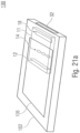
- Fig. 1a shows a schematic perspective view of a 3D multi-aperture imaging device 1000.
- the 3D multi-aperture imaging device 1000 includes an image sensor 12.
- the image sensor 12 includes a plurality of image sensor areas 58 11 - 58 24 .
- Each of the image sensor areas 58 11 - 58 24 includes a plurality of pixels, so that each of the image sensor areas 58 11 - 58 24 is designed to capture a partial image of an overall image.
- the overall image can be understood as an image of an overall visual field 72.
- the 3D multi-aperture imaging device 1000 may include two or more modules 11 or multi-aperture imaging devices 11.
- Each of the multi-aperture imaging devices 11a and 11b can be designed to at least almost completely or completely image the entire field of view and to form a channel of an at least stereoscopic detection system.
- a first channel can be, for example, a "right” channel, while a second channel can be a "left” channel.
- left/right is not intended to have a restrictive effect in this context, but can also be referred to with any other terms, such as top, bottom, middle, front, back or the like.
- the 3D multi-aperture imaging device 1000 includes, for example, a first module 11a with a first plurality of optical channels 16 11 - 16 14 , which are arranged to form an array 14 1 . Furthermore, the 3D multi-aperture imaging device 1000 includes a second module 11b with a second plurality of optical channels 16 21 - 16 24 arranged into a second array 14 2 . Modules 11a and 11b come with a Base distance BA is arranged offset from one another, so that at least stereoscopic information can be derived based on the resulting disparity.
- Each of the optical channels 16 11 - 16 24 is designed to capture a partial field of view 74a - 74d or partial field of view 74a - 74d of an overall field of view 72.
- At least adjacent partial visual fields can overlap with one another, for example the partial visual fields 74a and 74b or the partial visual fields 74b and 74c, but also diagonally adjacent partial visual fields, such as the partial visual fields 74a and 74c or 74b and 74d.
- the overlap can enable a simple calculation of the overall image from partial images in that the overlapping image areas provide information about how the partial images should be put together, for example as part of a stitching process.
- all partial areas 74a - 74d can also overlap with one another.
- the optical channel 16 11 is designed, for example, to image the partial field of view 74a or 74 11 onto the image sensor area 58 11 .
- the optical channel 16 21 is designed, for example, to image the partial field of view 74a or 74 21 onto the image sensor area 58 21 .
- each partial area 74a - 74d is imaged onto two image sensor areas by two optical channels.
- the partial area 74a is shown in such a way that it is imaged completely by the module 11a as a partial field of view 74 11 and completely by the module 11b as a partial field of view 74 21 , it is understood that the partial fields of view 74 11 and 74 21 are not completely identical are, for example based on manufacturing tolerances. However, such effects can be compensated for by calibration or the like and will be ignored below.
- the image sensor areas 58 11 - 58 14 and the optical channels 16 11 - 16 14 can be components of the first imaging module 11a, while the image sensor areas 58 21 - 58 24 and the optical channels 16 21 - 16 24 can be components of the second imaging module 11b.
- Each of the imaging modules 11a and 11b is designed, for example, to capture the overall field of view 72, which means that the 3D multi-aperture imaging device can capture the overall field of view 72 stereoscopically using the modules 11a and 11b.
- the partial visual fields 74 21 - 74 24 detected by the optical channels 16 21 - 16 24 can essentially correspond to the visual fields 74 11 - 74 14 , so that they also correspond to each other overlapping partial visual fields 74 21 - 74 24 essentially or completely overlap with the first partial visual fields 74 11 - 74 14 , which is represented by the designation 74a - 74d.
- the 3D multi-aperture imaging device includes a processor 1002 configured to receive image sensor data 1004 11 - 1004 14 from the first module 11a and image sensor data 1004 21 - 1004 24 from the second module 11b.
- the image sensor data 1004 11 - 1004 24 can, for example, include the signal or sample values of the image sensor areas 58 11 - 58 24 or can also include values derived therefrom, such as a pixel value or a color value.
- the image sensor can be designed as a charge-coupled device (CCD), as a complementary metal oxide semiconductor (CMOS) or as a differently formed image sensor.
- CMOS complementary metal oxide semiconductor
- the image sensor data 1004 11 - 1004 24 can each be the output values of the respective sensor or sub-sensor.
- the image sensor data 1004 11 - 1004 24 have information about the partial fields of view 74 11 - 74 14 and 74 21 - 74 24 mapped to the image sensor areas 58 11 - 58 14 and 58 21 - 58 24 .
- the processor 1002 is designed to provide an output signal 1006 that has a data header 1008 and payload data 1012.
- the data header 1008 includes information regarding the structure of the 3D multi-aperture imaging device 1000.
- the payload data 1012 has image information obtained from the pixels of the image sensor areas 58 11 - 58 14 and 58 21 - 58 24 . This is processed information, which will be explained in detail later.
- the output signal 1006 can therefore be an image signal. Alternatively, it can also be a video signal if several images of the entire field of view are recorded as a video.
- the 3D multi-aperture imaging device 1000 may optionally have an output interface 1014 through which the output signal 1004 can be output.
- the output interface 1014 may be a wireless or wired interface.
- the output interface 1014 may be permanently or temporarily connected to a memory, such as a hard drive or an external storage medium such as a Universal Serial Bus (USB) memory module or a memory card.
- the output interface 1014 may be designed to be wired or wireless Connect to another device, such as a computer or laptop.
- a memory module can also be arranged.
- modules 11a and 11b are shown such that the optical channels 16 11 and 16 21 the partial field of view 74a, the optical channels 16 12 and 16 22 the partial field of view 74b, the optical channels 16 13 and 16 23 the partial field of view 74c and the optical channels 16 14 and 16 24 capture the partial field of view 74d and are arranged in the modules 11a and 11b in the same order along a line extension direction 146 of the arrays 14 1 and 14 2 , the modules 11a and 11b can also be arranged in a different order and / or one have different numbers from each other.
- the optical channel 16 21 can detect a partial field of view 74a - 74d that is different from the optical channel 16 11
- the optical channel 16 22 can detect a partial field of view 74a - 74d that is different from the optical channel 16 12
- the optical channel 16 23 can capture a partial field of view that is different from the optical channel 16 13
- the optical channel 16 24 can capture a partial field of view 74a - 74d that is different from the optical channel 16 14 .
- the partial fields of view 74a - 74d can be imaged such that there is an equal, constant disparity between optical channels directed at the same partial field of view 74a - 74d, as shown in FIG Fig. 1a is described, or that, alternatively, different disparities may be present for different partial visual fields 74a - 74d.
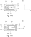
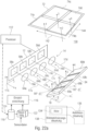
- Fig. 1b shows the 3D multi-aperture imaging device 1000 as it can be used according to exemplary embodiments described here.
- the image sensor 12 can be divided into two components 12 1 and 12 2 , one component 12 1 for the "right" optical channels 16 1 and the other component 12 2 for the "left" channels 16 2 .
- the right and left optical channels 16 1 and 16 2 are in the example of Fig. 1b constructed identically, but arranged laterally offset from one another by the base distance BA in order to obtain as much depth information as possible regarding the scene located in the field of view of the device 1000.
- Each plurality 16 1 and 16 2 of optical channels comprises four optical channels arranged next to one another.
- the individual “right” channels are distinguished by the second subscript.
- the channels are indexed from right to left. That is, the optical channel 16 11 , which is in Fig. 1b is not shown because of a partial removal chosen for the purpose of clarity, is arranged, for example, along the base distance direction 108, along which the left and right channels are arranged offset from one another at the base distance BA, at the extreme right edge, ie furthest away from the majority 16 2 left channels, with the other right channels 16 12 - 16 14 following along the base distance direction 108.
- the channels 16 11 - 16 14 therefore form a single-line array of optical channels, the line extension direction of which corresponds to the base distance direction 108.
- the left channels 16 2 are constructed in the same way. They are also distinguished from each other by the second subscript.
- the left channels 16 21 - 16 24 are arranged next to each other and in the same direction as the right channels 16 11 - 16 14 , namely so that the channel 16 21 is closest to the right channels and the channel 16 24 is furthest away latter.
- Each of the right channels 16 11 - 16 14 includes a corresponding optic, which, as shown in Fig. 1b is indicated, can consist of a lens system. Alternatively, each channel could have a lens.
- Each optical channel 16 11 - 16 14 receives one of overlapping partial fields of view 74a-d or 74 11-14 of the overall field of view 72, which overlap one another, as is the case in connection with Fig. 1a is described.
- the optical channel 16 12 images the partial field of view 74 12 onto an image sensor area 58 12
- the optical channel 16 13 an assigned partial field of view 74 13 onto a corresponding one Fig. 1b non-visible image sensor area 58 13 of the image sensor 12
- the optical channel 16 14 an assigned partial field of view 74 14 on a corresponding image sensor area 58 14 , which is also in Fig. 1b not shown due to obscurity.
- the image sensor areas 58 11 - 58 14 of the image sensor 12 or the component 12 1 of the image sensor 12 are arranged in a plane parallel to the base distance direction BA or parallel to the line extension direction 108, and lens planes of the optics of the optical channels 16 11 - 16 14 parallel.
- the image sensor areas 58 11 - 58 14 are arranged among one another with a lateral inter-channel distance 110, with which the optics of the optical channels 16 11 - 16 14 are also arranged among one another in this direction, so that the optical axes and beam paths of the optical channels 16 11 - 16 14 between the image sensor areas 58 11 - 58 14 and the optics 16 11 - 16 14 run parallel to each other.
- centers of the image sensor areas 58 11 - 58 14 and optical centers of the optics of the optical channels 16 11 - 16 14 are arranged on the respective optical axis, which run perpendicular to the aforementioned common plane of the image sensor areas 58 11 - 58 14 .
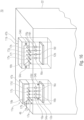
- the optical axes or beam paths of the optical channels 16 11 - 16 14 are deflected by a beam deflection device 18 1 and are thus provided with a divergence, which leads to the partial fields of view 74 11 - 74 14 of the optical channels 16 11 - 16 14 mutually facing each other only partially overlap, such as B. so that in pairs the partial visual fields 74 11 - 74 14 overlap at most 50% in the solid angle.
- the beam deflection device 18 1 can, as in Fig. 1b is indicated, for example for each optical channel 16 11 - 16 14 have a reflective facet, which is tilted differently relative to one another under the channels 16 11 - 16 14 .
- a mean inclination of the reflective facets relative to the image sensor plane deflects the overall field of view of the right channels 16 11 - 16 14 in a direction that is, for example, perpendicular to the plane in which the optical axes of the optics of the optical channels 16 11 - 16 14 are in front of or .
- the beam deflection device 18 1 could also use prisms for refractive beam deflection of the individual optical axes or beam paths of the optical channels 16 11 - 16 14 .
- the beam deflection device 18 1 provides the beam paths of the optical channels 16 11 - 16 14 with a divergence such that the channels 16 11 - 16 14 , which are actually arranged next to one another linearly in the direction 108, cover the overall field of view 72 two-dimensionally or in a second direction perpendicular to the line extension direction 108 .
- the beam paths or optical axes could also deviate from the parallelism described, but that the parallelism of the beam paths of the optical channels could still be so pronounced that the partial fields of view that pass through the individual channels 16 11 - 16 14 are covered or imaged onto the respective image sensor areas 58 11 - 58 14 , without further measures, such as beam deflection, would largely overlap, so that in order to cover a larger overall field of view through the multi-aperture imaging device 1000, the beam deflection device 18 also includes the beam paths An additional divergence ensures that the partial visual fields of the channels 16 11 - 16 14 overlap each other less.
- the beam deflection device 18 ensures that the overall field of view is averaged over all azimuthal angles or over all transversal directions Has an opening angle that is greater than 1.5 times the corresponding average opening angle of the partial fields of view of the optical channels 16 11 - 16 14 .
- the left channels 16 21 - 16 24 are now also constructed and positioned relative to the respective assigned image sensor areas 58 21 - 58 24 , which are in the same plane as the optical axes of the channels 16 11 - 16 14 parallel optical axes of the optical channels 16 21 - 16 24 are deflected by a corresponding beam deflection device 18 2 , so that the optical channels 16 21 - 16 24 record the same overall field of view 72 in an almost congruent manner, namely in partial fields of view 74 21 - 74 24 , into which the overall field of view 72 is divided two-dimensionally, which overlap each other, and each of which almost completely overlaps with the corresponding partial field of view 74 11 - 74 14 of a corresponding channel of the right channels 16 11 - 16 14 .
- the image sensor areas 58 11 - 58 24 can, for example, each be formed from an image sensor chip, as is described for the image sensor 12 in FIG. 1a , consist of a few image sensor chips, two or just one common image sensor chip.
- the 3D multi-aperture imaging device includes a processor 1002, which takes over the task of, for example, the images captured during an acquisition by the 3D multi-aperture imaging device 1000 through the right optical channels 16 11 - 16 14 to a first to merge the overall picture.
- the problem that has to be overcome is the following: Due to the inter-channel distances 110 between adjacent channels of the right channels 16 11 - 16 14 , the images that are recorded through the channels 16 11 - 16 14 in the image areas 58 11 - 58 14 are recorded, not simply or translationally moved and placed on top of each other. In other words, they cannot be easily put together.
- Disparity is called the lateral offset along the direction BA, 108 or 110 in the images of the image sensor areas 58 11 - 58 14 when recording the same scene, which correspond to one another but are in different images.
- the disparity of mutually corresponding image content depends in turn on the distance of this image content in the scene, ie the distance of the corresponding object from the device 1000.
- the processor 1002 could now try to evaluate disparities among the images of the image sensor areas 58 11 - 58 14 itself, around these pictures with each other to merge into a first overall picture, namely a “right overall picture”.
- the disadvantage is that the inter-channel distance 110 is present, and thus creates the problem that the inter-channel distance 110 is, on the other hand, also relatively small, so that the depth resolution or estimation is only inaccurate.
- the processor of Fig. 1b therefore uses in the overlap area 114 between the partial fields of view 74 11 and 74 12 to merge disparities in a pair of images, one of which is recorded through one of the left channels 16 21 or 16 22 , the imaged second partial field of view, namely 74 21 or 74 22 , overlapped with the overlap area 114.
- the process 1002 for merging the images of the image sensor areas 58 11 and 58 12 evaluates disparities in images, one of which is captured by one of the image sensor areas 58 21 or 58 22 and another by one of the channels involved in the overlap area 114, ie a Image captured by one of the image sensor areas 58 11 or 58 12 .
- Such a pair then has a base spacing corresponding to the base base spacing BA plus/minus one or none of a channel base spacing 110.
- the latter base spacing is significantly larger than a single channel base spacing 110, which is why the disparities in the overlap area 86 are easier for the processor 1002 to determine.
- the processor 1002 therefore evaluates disparities that arise with an image of the left channels, preferably, but not exclusively, between images from one of the right channels and one of the left channels.
- the processor 1002 takes that part of the partial field of view 74 11 that does not overlap with one of the other partial fields of view of the right channels more or less directly from the image 58 11 and does the same for the non-overlapping areas the partial visual fields 74 12 , 74 13 and 74 14 based on the images of the image sensor areas 58 12 - 58 14 , the images of the image sensor areas 58 11 - 58 14 being recorded simultaneously, for example. Only in the overlap areas of adjacent partial visual fields, such as. B.
- the processor then draws 1002 disparities from image pairs whose overlap in the overall field of view 72 overlaps in the overlap area, but of which in the majority but not exclusively one is recorded through one of the right channels and the other through one of the left channels, such as B. again at the same time.
- the processor 1002 could warp all images of the right channel according to an evaluation of disparities between pairs of images, one of which was acquired through the right channels and the other through the left channels .
- the overall image that is calculated by the processor 1002 for the images of the right channels could be virtually at one point of view not only in the overlapping area of the partial fields of view 74 11 - 74 14 of the right channels, but also in the non-overlapping area.
- warped which lies, for example, laterally in the middle between the right channels 16 11 - 16 14 , in that disparities from image pairs are also evaluated by the processor 1002 for those areas of the partial visual fields 74 11 - 74 14 that do not overlap each other where one image was captured through one of the right channels and another image was captured through one of the left channels.
- the 3D multi-aperture imaging device 1000 from Fig. 1b is not only capable of generating an overall image from the images of the right channels, but the 3D multi-aperture imaging device 140 of Fig. 1b is also able, at least in one operating mode, to generate an overall image of the images of the left channels and/or a depth map in addition to the overall image of the right channels from a recording in addition to the overall image of the first channels.
- the processor 1002 is designed, for example, to merge images that are recorded through the left optical channels 16 21 - 16 24 or the image sensor areas 58 21 - 58 24 into a second overall image, namely an overall image of the left channel, and to use disparities in a pair of images in an overlap area of laterally adjacent partial visual fields 74 21 - 74 24 of the left optical channels, the majority of which but not exclusively one of which is recorded through a right optical channel 16 11 - 16 14 and overlaps with the corresponding overlap area of the pair of partial visual fields 74 21 - 74 24 , and the other is preferably recorded through one of the left optical channels, the partial field of view of which overlaps with the respective overlap area.
- the processor 1002 outputs two overall images for one recording, namely one for the right optical channels and the other for the left optical channels. These two overall images could, for example, be fed separately to a user of the user's two eyes and thus lead to a three-dimensional impression of the recorded scene.
- the processor 1002 generates a depth map in addition to the overall image for the right channels using disparities in pairs of images that have at least one pair for each of the right channels 16 11 - 16 14 that have a Has an image that is recorded through the respective right channel, and another image that is recorded through one of the left channels.
- the depth map is generated by the processor 1002
- the two alternatives can also both be processed by the processor 1002: It could first generate the two overall images, namely one for the right optical channels and the other for the left optical channels, as described above, by merging the images of the right channels in the overlap areas between the images of the right channels, disparities from pairs of images are also used, one of which belongs to the images of the left channels, and when merging the images of the left channels, disparities are also used in the overlap areas between the images of the left channels Pairs of images are used, one of which belongs to the images of the right channels, in order to then generate an overall image with an associated depth map from the overall images obtained in this way, which represent the scene in the overall field of view from different perspectives, such as. B.
- the processor used 1002 then the right and left overall image, as it were as an interim result from the previous fusion of the left and right individual images.
- the processor here evaluated disparities in the two intermediate result overall images in order to obtain the depth map and carry out the warping or warping/merging of it.
- processor 1002 can perform the evaluation of disparities in a pair of images, for example, by cross-correlating image regions.
- the overall visual field 72 is covered differently by the partial visual fields of the left channels on the one hand and by the partial visual fields of the right channels on the other hand, there may also be more or fewer than four channels (regardless of whether they belong to the left or right channels).
- overlap as e.g. B. was also the case with the mutual overlap between the overlap areas of partial visual fields adjacent in the row direction or column direction in the previous examples, where the partial visual fields of the right channels and the partial visual fields of the left channels were each arranged in columns and rows.
- the number of sources of disparity in general is that: N 2 , where N denotes the number of channels with overlapping partial visual fields.
- the processor 1002 optionally carries out, among other things, a channel-by-channel correction of perspective imaging distortions of the respective channel and/or an adjustment of the image brightness both in each channel and between the channels.
- Fig. 1b was in many ways merely exemplary.
- the number of optical channels is not four, but is somehow greater than or equal to 2 or lies between 2 and 10, both inclusive, and the overlap area of the partial visual fields of the right optical channels can, as far as for each partial visual field or each channel, be the pair the largest overlap to the respective partial field of view is considered, in terms of area for all these pairs lie between 1/2 and 1/1000 of an average image size of the images recorded by the image areas 58 11 - 58 14 , measured for example in the image plane, ie the plane of the image sensor areas.
- the number of left optical channels, N L , and right optical channels, NR does not necessarily have to be the same and a division of the total field of view 72 into the partial fields of view of the left channels and the partial fields of view of the right channels is not approximately the same has to be like this Fig. 1b was the case.
- the partial visual fields and their overlap it can be the case, for example, that the partial visual fields extend into one another by at least 20, 100, 500 or 1000 pixels, as long as an image distance or object distance of 10 m is considered, at least for all pairs with the largest overlap, This can apply to the right channels as well as the left channels.
- the left optical channels or the right optical channels could also form a two-dimensional array of optical channels.
- the single-row arrays could have a collinear row extension direction.
- the arrangement of Fig. 1b is, however, advantageous because it results in a minimum overall height perpendicular to the plane in which the optical axes of the optical channels, ie both the right and the left channels, lead before or without beam deflection.
- the image sensor 12 it was already mentioned that it can be formed from one, two or more chips.
- one chip could be provided per image sensor area 58 11 - 58 14 and 58 21 - 58 24 , whereby in the case of several chips, the same can be attached to one or more circuit boards, such as. B. a board for the left channels or the image sensors of the left channels and a board for the image sensors of the right channels.
- Fig. 1b It is therefore possible to place adjacent channels within the channels of the right or left channels as close as possible, with the channel spacing 110 corresponding approximately to the lens diameter in the optimal case. This results in a small channel spacing and therefore a low disparity.
- the right channels on the one hand and the left channels on the other hand can be arranged at any distance BA from one another, so that large disparities can be achieved. Overall, there is the possibility of artifact-reduced or even -free image fusion and the creation of depth maps with a passive optical imaging system.
- Fig. 2 additionally shows that the processor 1002 serves as a basis for merging images that have been captured by a pair of image sensors onto which a pair of optics of the left channels images a pair of immediately adjacent partial visual fields, as is exemplary for the partial visual fields 74 11 and 74 12 is the case, beyond this pair of images there are disparities in one or more of the total 4 2 , ie "two out of four", can use disparity sources, ie pairs of images from image sensor areas that relate to disparities to scene objects in the overlap area between this pair of immediately adjacent partial fields of view.
- disparity sources ie pairs of images from image sensor areas that relate to disparities to scene objects in the overlap area between this pair of immediately adjacent partial fields of view.
- the processor may use one or more of additional sources 2 to 5 for fusion support.
- the processor 1002 also calculates a depth map according to the alternative mentioned above
- the processor can determine the depth map at each point of the field of view 72 from evaluating the disparities of more than one pair of images, one through a right channel and one through a left channel is imaged onto a respective image sensor area and recorded by the latter, namely at points at which another pair overlaps each other beyond the partial field of view of a right channel and the partial field of view of a left channel.
- Fig. 2 This is only the case in the overlap areas of partial visual fields of right channels, which are identical to the overlap areas of partial visual fields of left channels due to the congruence with the partial visual fields of left channels, but in other exemplary embodiments the congruence may not be present.
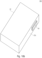
- the 3D multi-aperture imaging device of Fig. 1a and 1b can, for example, be installed in a flat housing of a mobile device, such as a B. a mobile phone, be installed.
- the plane of the image sensor areas 12 11 - 12 14 and 12 21 - 12 24 as well as any lens plane of the optics of the left and right channels can run parallel to a thickness direction of the flat housing. Due to the beam deflection by the beam deflection device 18 1 or 18 2 , the overall field of view of the 3D multi-aperture imaging device would lie, for example, in front of a front, in which, for example, a screen of the mobile device is positioned, or in front of a back of the mobile device.
- the output signal 1006 has two components, namely the data header 1008 and the payload data 1012, the data header 1008 and the payload data 1012 can also be arranged interleaved with one another or in any order, as long as there is an assignment of the respective ones Content about the data header 1008 or the payload data 1012 is possible. Furthermore, the output signal 1006 can also have other components, such as sequential numbers or checksums.
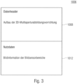
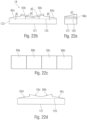
- Fig. 3 shows a schematic view of a structure of the output signal 1006, which has the data header or header 1008 and the payload 1012.
- the data header 1008 includes information regarding the structure of the 3D multi-aperture imaging device.
- the information regarding the structure of the 3D multi-aperture imaging device can take into account a number of structural data, including a number of imaging modules, an assignment of the optical channels to the partial visual fields, a size and / or arrangement of the partial visual fields in the overall visual field or the like.
- the payload data 1012 includes image information of the image sensor areas. These can be, for example, processed or unprocessed image sensor values.
- the image information can, for example, be available continuously for individual pixels or already sorted with respect to the overall image.
- Fig. 4 shows a schematic view of a structure of the output signal 1006, in which the data header 1008 has the description of the 3D multi-aperture imaging device and information regarding a segmentation of the overall field of view.
- the information from the segmentation of the overall field of view can relate to the first or second partial fields of view of the first or second or a further module of the 3D multi-aperture imaging device.
- the information can, for example, include information about the number of partial visual fields in which the overall visual field is segmented, for example based on which number of optical channels is arranged in the respective imaging module.
- the segmentation can be the same for at least two or all mapping modules, but can also differ from one another for at least two or all mapping modules.
- the at least two imaging modules of the 3D multi-aperture imaging device are constructed the same.
- a single statement regarding the segmentation of the field of view in the data header 1008 may be sufficient, since this information can be transferred to all imaging modules.
- at least a first imaging module is designed differently from a further imaging module, which means that the number and/or arrangement of the partial visual fields in the overall visual field differs.
- the data header 1008 can contain the information regarding the segmentation of the field of view for two, several or even all of the imaging modules of the 3D multi-aperture imaging device.
- the information regarding the segmentation of the overall visual field can therefore relate to a position and/or orientation of a partial visual field in the overall visual field and/or relate to which image sensor area the partial visual field is imaged on.
- the information regarding the structure of the 3D multi-aperture imaging device can relate to the number, the design, the orientation of the Imaging modules in space or distances between the imaging modules in the 3D multi-aperture imaging device, ie, the base distance BA.
- the description of the 3D multi-aperture imaging device may refer to the structure of the 3D multi-aperture imaging device.
- the data header 1008 may contain information about what base spacing the imaging modules have, what number of optical channels are arranged in the array 14 1 and/or 14 2 or what order or orientation they have in space or in the imaging modules. Alternatively or additionally, a position of the imaging modules and/or an orientation of them in space can also be specified. With a comparable design of the imaging modules, a single piece of information regarding this design may be sufficient to describe all imaging modules of the 3D multi-aperture imaging device.
- the processor can be designed to form the output signal such that the data header 1008 has information regarding the base distance BA.
- the payload data includes pixel-by-pixel image information of the individual optical channels of the 3D multi-aperture imaging device.
- the information of the pixels of the image sensor areas of the image sensor can be arranged sequentially one after the other in the payload data 1012 according to a predefined order.
- additional and/or alternative information can be arranged.
- the image information ie the pixel values
- an image format such as JPEG, Blender, IGES or the like, with and without compression can be implemented as the processed form.
- Information relating to a three-dimensional image can be part of the user data 1012, but also a plurality of two-dimensional images from which three-dimensional effects or information can then be derived.
- the processor 1002 is designed according to an exemplary embodiment to form the output signal such that the payload data includes information regarding the compressed image data.
- the processor 1002 may be designed to, for example, sequentially evaluate each image sensor area and thus each partial field of view sequentially and to process the image information obtained from the pixels of the image sensor areas.
- the pixel-by-pixel image information of the useful data 1012 can have a structure in which each partial field of view is described one after the other in a mosaic-like manner.
- a mosaic-like shape can be obtained, for example, by interleaving the partial visual fields 74a-d in the overlap areas 114.
- the processor 1002 is designed to preprocess the image information of the image sensor areas, for example in order to obtain a demosaiced overall image.
- the processor 1002 is designed to form the output signal 1006 so that the payload data 1012 contains information relating to the overall image. For example, each column or each line of the overall image can be reproduced sequentially as pixel-by-pixel image information. In contrast, with the mosaic-like display, each partial image can be displayed in columns or rows.
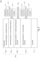
- the Fig. 5a and 5b 10 show a schematic view of a structure of the output signal 1006, which is formed by the processor 1002 by taking into account a variety of information sources. They are there Fig. 5a and 5b to be understood as a figure, that means that the in Fig. 5b shown section of the data header 1008 part of the in Fig. 5a data header shown is 1008 and that the in Fig. 5b
- the useful data 1012 shown are also part of the output signal 1006, like those in the Fig. 5a shown parts of the data header 1008.
- components 1008a, 1008b, 1008c and 1008d are shown as separate blocks of information, information contained in the data header 1008 can have any structure with one another.
- the segmentation shown is for illustrative purposes only and is not intended to have a restrictive effect.
- the processor 1002 may be configured to form the output signal 1006 such that the data header includes information regarding the number of imaging modules 11.
- the imaging modules can be designed to completely capture the entire field of vision, which means that the information regarding the number of imaging modules can be equated to a number of total images of the entire field of vision.
- the data header has information about which Number of optical channels per imaging module 11 is arranged.
- the data header 1008 may have information about which number of pixels are arranged along a first and/or second image axis for example, can be described as horizontal and vertical.
- the information can relate to the number of pixels recorded per partial image, i.e. image sensor area, and/or the overall image or pixels arranged in the overall image.
- the processor can be designed to form the output signal 1006 such that the payload data contains information regarding the image sensor areas 58, for example regarding a number of pixels along a row and/or column or a geometric extent of the image sensor areas 58.
- the respective information can be identical for all imaging modules 11 and/or for the optical channels, i.e. the partial images, so that the presence of the information regarding all imaging modules and/or partial images leads to a sufficient description.
- individual information can also be arranged individually for each imaging module or partial image in the data header 1008.
- This foregoing description of the A) number of modules, B) number of channels per module, and C) number of pixels along the image axes and/or the base spacing may be arranged as a meta-description regarding the structure of the 3D multi-aperture imaging device 1000 and is as element 1008a of the Data header 1008 marked.
- the information can be inserted individually and in any combination with one another by the processor, for example a specification of a model number or the like of an imaging module or 3D multi-apeture imaging device can provide similar information if the implementation of the module or device is thereby encoded.
- the processor 1002 is designed to add information to the output signal 1006 about which optical channel looks into which section of the overall field of view and/or what distance the optical channels are from one another. This can be particularly advantageous for the individual partial images in the output signal 1006.
- a geometry description that can be inserted by the processor 1002 into the data header 1008 of the output signal 1006 is identified as element 1008b of the data header 1008.
- the geometry description can relate to D) a pixel size of the pixels of the image sensor areas 58 of the image sensor 12.
- the pixels have identical or comparable sizes.
- the pixel size can therefore be specified globally for all pixels.
- the total number of pixels of the image sensor areas 58 have different sizes from one another.
- the pixel size can be changed for each different version of the Pixels and for assigning the size to the respective pixels can be arranged in the element 1008b.
- the processor 1002 can be designed to form the output signal 1006 such that the data header 1008 has information regarding a number of pixels for a first image extension direction and a number of pixels for a second image extension direction at least for one of the image sensor areas 58 can.
- This can, for example, be the extension directions along which the partial visual fields extend in space.
- the first and second directions may be perpendicular to each other and correspond to a number of rows or columns.
- the processor 1002 can be designed to E) insert two-dimensional (X/Y) or three-dimensional (X/Y/Z) coordinates for one, several or each optical channel of each module 11 or at least insert a relative positioning to one another.
- the coordinates can therefore be local coordinates of an arrangement of the optical channels 16 with respect to other optical channels and/or global coordinates, i.e. H. an arrangement of the optical channels within the 3D multi-aperture imaging device. In both cases, an arrangement of the optical channels 16 in the module 11 and/or in the 3D multi-aperture imaging device 1000 can be described.
- the processor 1002 can be designed to form the output signal 1006 such that the data header 1008 for at least one of the optical channels 16 has information regarding a spatial coordinate of the at least one optical channel 16 in the 3D multi-aperture imaging device 1000.
- the output signal 1006 can be formed in such a way that it contains information about a geometric arrangement of the optical channels.
- the element 1008b of the data header 1008 can further be formed by the processor 1002 in such a way that it includes information F) regarding a field angle range of at least one optical channel or also the imaging module.
- the field angle range can be specified as an interval along one, preferably along two image directions. This can also be referred to as "ranging from ising to ..""or viewing direction ⁇ xy".
- the field angle range can be specified by a central direction of the module 11 or the optical channel 16 and can be supplemented by an extension of the field angle range along at least one, preferably two, image axes.
- the data header 1008 may additionally include an optional element 1008c that includes information G) about environmental conditions of the 3D multi-aperture imaging device 1000.
- an optional element 1008c that includes information G) about environmental conditions of the 3D multi-aperture imaging device 1000.
- a pressure of an atmosphere or environment surrounding the 3D multi-aperture imaging device, an ambient temperature of the 3D multi-aperture imaging device, an operating temperature of the 3D multi-aperture imaging device, a time of image capture or generation of the output signal 1006 and / or a position of the 3D multi-aperture imaging device in the Data header 1008 must be inserted.
- the location can be determined, for example, using a positioning system such as GPS, Galileo or Glonass or provided by an external data source such as a sensor.
- the processor may be designed to form the data header 1008 such that it includes information about an orientation or viewing direction of the at least one optical channel, a module and/or the 3D multiperture imaging device.
- the processor can be designed to form the data header 1008 such that the element 1008c has camera-specific information regarding at least one autofocus drive.
- the at least one autofocus drive can, for example, have been used to focus the captured image.
- the camera-specific information can include information about focusing of the image information or user data. This can be a focusing system used jointly for all modules, ie an autofocus drive, for module-specific focusing, ie at least two autofocus drives, or channel-specific focusing, ie having a large number of autofocus drives.
- the information can be the indication of a global or relative position of an element of the autofocus drive and/or a controlled variable, such as a current variable or a voltage variable for controlling the autofocus drive. The global or relative position can be reconstructed from the controlled variable so that conclusions can be drawn about the focusing.
- the data header 1008 of the output signal 1006 may also be as described in FIG Fig. 5b is shown, an optional element 1008d having information regarding possible corrections.
- the element 1008d and thus the data header 1008 can contain information regarding an H) indication of at least one optical channel of the 3D multi-aperture imaging device, regarding an I) vignetting, i.e. H. a shading of the overall image or partial image towards the edge of the image, and / or information about J) defective pixels on the image sensor or the image sensor areas 58.
- H indication of at least one optical channel of the 3D multi-aperture imaging device
- I) vignetting i.e. H. a shading of the overall image or partial image towards the edge of the image
- J defective pixels on the image sensor or the image sensor areas 58.
- Each of the information H), I) and J) can also be used later to correct the image .
- the payload 1012 can, as is the case in connection with the Fig. 4 is described by K), include pixel-by-pixel image data.
- identifying information relating to the pixels can be continuously specified, for example, according to option a), color information.
- color information Based on an image sensor used, for example an assignment of four color values per pixel according to a red-green-green-blue scheme, for example according to a Bayer filter or according to a red-green-blue-white arrangement or the like.
- the respective color information and/or brightness information can be arranged continuously for continuous pixels in the payload data 1012.
- the color information can also be arranged by the processor 1002 following another, reconstructable scheme.
- the image data can also have pixel-by-pixel depth data, have information about a segmentation of pixels into pixel clusters and/or have information about depth information and/or distance information regarding pixel clusters.
- the image data in the payload data can be arranged in a cluster-wise manner and the depth data or the cluster information can be arranged accordingly in the data header.
- the pixel values can optionally be arranged continuously without separating information, wrapping information or intermediate information, for example if the size of each image can be derived from the header data, for example by information C).
- a start/stop character string can be arranged between the pixel values or between some pixel values.
- the start/stop string may include at least one bit and indicate that a new portion of the image begins, such as a new field, a new column of images, or a new line of images. This means that the payload contains information regarding a line break or a column break of the captured image. This can be advantageous if the aforementioned information C) is absent in the header data.
- information can be inserted in the header data for each group of pixels, which enables an identification of the imaging module 11 and the optical channel 16, that is to say an assignment of the pixels to the module 11 and the optical channel 16, as it is is indicated by option L)c).
- the image data is arranged as M)a) raw data (RAW) and/or as M)b) compressed image data and/or as M)c) demosaiced image data in the payload data 1012.
- the image data can have pixel-by-pixel depth data, have information about a segmentation of pixels into pixel clusters and/or have information about depth information and/or distance information regarding pixel clusters.
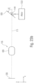
- Fig. 6 shows a schematic overview of the output signal 1006, which may have the elements 1008a - 1008d of the data header 1008.
- design data 1015 of the 3D multi-aperture imaging device (3D-MAAV) can be taken into account by the processor 1002. This can include, for example, the pixel size D).
- calibration data 1016 can also be used by the processor 1002, for example by the processor 1002 reading it from a data memory.
- the calibration data for example the field angle range F) can be the same across a series of multi-aperture imaging devices of the same or identical design.
- individual calibration data 1018 from the processor 1002 may also be used, such as calibration data that is unique to the 3D multi-aperture imaging device, such as the actual coordinates E) of the optical channels in the 3D multi-aperture imaging device. For example, manufacturing tolerances can be compensated for.
- design data 1015' can be utilized by the processor 1002 in such a way that the distortion H) of the optical channels and/or the vignetting I) are taken into account.
- this data or information H) and/or I) can also be used as calibration data 1016', which is identical for the series of 3D multi-aperture imaging devices.
- calibration data 1018' can be used by the processor 1002 are, for example, by measuring the pixels in order to detect the defective pixels J) and to take this into account in the useful data and/or in the correction data 1008d.
- the output signal 1006 can, for example, be stored as a file or data block in a memory or transmitted as a signal.
- a number of optical channels per image, a number of modules and/or a number of horizontal and vertical pixels per partial image can be specified globally for all modules 11 in the data header 1008.
- the number of modules can be a number of quasi-redundant images, which represents a multiplicity of views.
- a stereo recording can be obtained with a number of two modules, a triplet recording with a number of modules and a Quattro recording with a number of four modules.
- several, i.e. H. more than four imaging modules or multi-aperture imaging devices can be arranged.
- the 3D multi-aperture imaging device has three multi-aperture imaging devices, i.e. H. Modules, it comprises, for example, a third plurality of optical channels for imaging mutually overlapping third partial visual fields of the overall visual field with the first partial visual fields onto third image sensor areas of the image sensor, the first and second plurality of optical channels being laterally separated from one another by a basic distance are arranged offset.
- the processor is designed to receive image sensor data from the image sensor, which has information about the third partial fields of view imaged on the third plurality of image sensor areas, and is designed to provide the output signal such that the useful data from the pixels of the first image sensor areas, the second Image sensor areas and the third image sensor areas have image information obtained.
- the information in the data header can relate to a structure or arrangement of the three modules. Alternatively, as already described, a larger number of modules is possible.
- a number of modules for at least two modules 11 or for each module 11 a number of optical channels per image and/or a number of pixels horizontally and vertically per partial image can also be specified, for example if the modules are different from one another.
- Individual and global information regarding the modules can also be arranged together in the output signal 1006, which can lead to redundant information reproduction.
- the geometry data 1008b of the channel arrangement can refer to a number and/or designation of the module, to a number and/or designation of the optical channel in the respective module 11, to a two-dimensional or three-dimensional coordinate of the channel or module and/or to an angular orientation at least of an optical channel in the 3D multi-aperture imaging device.
- the geometry data may be derived and/or provided based on knowledge of the design data, such as in a memory. Alternatively, the geometry data can also be determined by a measurement, which can lead to at least partial compensation of manufacturing tolerances.
- the geometry data can also be dependent on external influencing variables such as temperature and pressure. Knowledge of these sizes during further image processing or image reconstruction enables a correspondingly adapted correction to be carried out.
- camera information such as a manufacturer, a model, an aperture number, an exposure time, an ISO value, a light value, a focal length, flash usage and/or flash strength
- the camera information can contain information about position data or information about a controlled variable (control current, control voltage) of the autofocus drives.
- the geometry data 1008b can further specify a field angle range and/or a central field or viewing direction as well as an extent (horizontal/vertical) of the field angle along the image axes on a channel-by-channel basis, i.e. for each optical channel.
- the field angle data can be design data.
- the field angle data can also be measured in the course of a calibration, whereby the calibration can be determined on the specific structure or can correspond to typical values that are determined on a representative specimen.
- additional parameters such as pressure and temperature can be included to select or calculate the data set, whereby the data sets can be obtained from design data or from calibration, whereby the calibration can be determined on the specific structure and corresponds to typical values that can be obtained on a representative specimen were determined.
- the geometry data 1008b can alternatively or additionally have a number of rows and/or columns per optical channel, also globally or individually per channel. Alternatively or additionally, information regarding the pixel size may be inserted by the processor 1002.
- Element 1008d may include additional environmental conditions such as pressure, temperature, time, or location. Such information can be obtained by connecting the processor 1002 to external sensors in the Fig. 6 Sensor data 1022 shown are received from the processor 1002.
- the optional element 1008d may contain correction data for the optics.
- design data relating to the optical and/or perspective (Keystone) distortion can be accessed by the processor 1002 and processed by the processor 1002.
- measured data from a calibration can be processed, whereby the calibration can be determined on the specific structure or can correspond to typical values that were determined on a representative example of a 3D multi-aperture imaging device.
- vignetting I it can be global or channel-specific design data or calibration data, as explained above.
- information J) regarding defective pixels can be arranged on the image sensor 12.
- the payload 12 i.e. the payload
- the image data can be arranged as RAW, as compressed or packed image data, such as JPEG or the like, and/or as a demosaiced image in the payload data 1012.
- Different files containing geometry data, correction data and payload can also be generated by the processor 1002, that is, the output signal 1006 can be generated in a disjointed manner.
- the output signal 1006 can also be generated so that a separate payload file is output by the processor 1002 for each optical channel.
- the channel-wise or cluster-wise depth information can also be inserted into the data header 1008 by the processor 1002 in the form of geometry data.
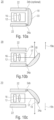
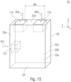
- Fig. 7 shows a schematic view of a multi-aperture imaging device 2000 according to a second aspect of the exemplary embodiments described herein, which can be arranged, for example, as an imaging module 11 in the 3D multi-aperture imaging device 1000.
- the multi-aperture imaging device 2000 is designed to image the partial fields of view 74a - 74d onto the image sensor 12 by means of the optical channels 16a - 16d, each of which has at least one optic or lens 64a - 64d.
- the array 14 is arranged, for example, along the line extension direction 146.
- the optical channels 16a - 16d are thus arranged in a one-dimensional array 14, which means that the optical channels 16a - 16d are arranged in a single row, for example.
- the overall field of view 72 can extend in space along a first image direction 142 and along a second image direction 144, whereby the directions 142 and 144 can be perpendicular to one another.
- the partial fields of view 74a - 74d can be arranged next to one another and overlapping one another along the direction 142, so that an extension of the image along the direction 144 is determined by the number of pixels and / or by the field angle of the optical channels 16a - 16d along the direction 144 and the Expansion of the image along the direction 142 is influenced or determined by the number of pixels and the field angle of the optical channels 16a - 16a along the direction 142 and additionally by the number of partial fields of view 74a - 74d and by the overlap factors.
- the plurality of optical channels 16a - 16d form the one-dimensional array 14, which is arranged in space along the direction 144 and 146, while the partial fields of view 74a - 74d of the overall field of view also form a one-dimensional array, which is vertical along the direction 142 to the direction 144 is arranged.
- the multi-aperture imaging device 2000 can thus have the feature that a conversion takes place between an arrangement direction of the array 14 and an arrangement of the corresponding partial visual fields 74a - 74d in space. This can be done, for example, by a respective viewing direction of the optical channels 16a - 16d.
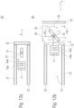
- the multi-aperture imaging device 2000 can have a beam deflection device, not shown, which carries out such a deflection.
- the multi-aperture imaging device 2000 can advantageously be arranged in systems in which images are essentially captured that have a significantly greater extent along a first image direction 142 compared to a second image direction 144.
- This can apply, for example, to camera systems in vehicles that track the vehicle's route along a horizontal direction capture.
- the direction 142 can be a horizontal direction, for example.
- the optical channels 16a-16d may be arranged along a vertical direction in the vehicle. It is understood that the directions 142 and 146 are interchangeable, which means that the horizontal and vertical information should not have a restrictive effect.
- the multi-aperture imaging device 2000 can be arranged in at least two versions as modules 11a and 11b in the 3D multi-aperture imaging device 1000. Deviating from the illustration, the 3D multi-aperture device may have fewer or more than 4 channels, but at least two.
- Fig. 8 shows a schematic block diagram of a device 3000 for processing the output signal 1006.
- the device 3000 may have a wireless or wired interface 1023 for receiving the output signal 1006.
- the signal 1006 is therefore referred to as the input signal for the device 3000.
- the device 3000 includes a processor 1024 for processing the payload data 1012 of the input signal 1006, taking into account the information regarding the structure of the 3D multi-aperture imaging device 1000 for at least first image sensor information of a partial field of view 74 11 - 74 24 of the first module 11a and a partial field of view 74 21 - 74 24 the second module 11b. Additionally, processor 1024 may be configured to process other or additional information from data header 1008.
- a function that can be implemented by the processor 1024 is, for example, a subsequent change in focus of varying areas in the image data that are contained in the payload data 1012 of the input signal 1006.
- the device 3000 can be designed to output an image signal 1026 that enables the post-processed image data to be displayed.
- the signal 1026 can be displayed on an optional monitor 1028 or display 1028.
- the signal 1026 can also be transmitted wired or wirelessly, for example to another device.
- the other device may be another processing device or a storage element.
- the device 3000 may be configured to process the output signal even if it indicates that a number of modules greater than two were used to capture the entire field of view.
- the recorded image data of the 3D multi-aperture imaging device 1000 can thus be stored in a format that enables the calculation of three-dimensional object data and the subsequent, i.e. after the actual image recording, object distance-dependent definition of the areas to be focused.
- the data format can consist of or at least have a header and a payload area. Descriptive data of the image-capturing multi-aperture imaging system and possibly additional sensor data can be listed in the header area, whereas essentially the pixel-by-pixel image data can be listed in the payload area.
- Multi-aperture imaging systems obtained in this way can have a linear channel arrangement, i.e. H. have optical channels arranged in a single row and have a small or even minimal size.
- the aspects described above enable customizable three-dimensional image capture and display.
- the depth of field range can be determined subsequently.
- multi-aperture imaging devices and 3D multi-aperture imaging devices each of which can be combined as additional features with the features of the 3D multi-aperture imaging device 1000.
- Fig. 9a shows a schematic side sectional view of a device 10 according to an exemplary embodiment in a first operating state.
- the device 10 may be a mobile or immobile device, such as a cell phone, a smartphone, a mobile computer such as a tablet computer, and/or a mobile music player.
- the device 10 comprises a multi-aperture imaging device 11, which has an image sensor 12, an array 14 of optical channels 16 arranged next to one another and a beam deflection device 18.
- the beam deflecting device 18 is designed to deflect a beam path 17 of the optical channels 16 and will be described in detail later.
- the device 10 comprises a housing 22 which has outer surfaces 23 which enclose a housing volume 24.
- This means that the housing volume 24 can include an internal volume of the housing 22 and the volume of the housing 22.
- the housing volume also includes a volume that is claimed by the housing walls and is thus enclosed by the outer surfaces 23 of the housing.
- the housing 22 can be transparent or opaque and can include, for example, plastic materials and/or metal materials.
- the beam deflection device 18 has a first position within the housing volume 24.
- the housing 22 and/or components arranged in the housing 22 can block the beam path 17 of the optical channels 16 after deflection by the beam deflection device 18, so that a field of view 26 arranged outside the housing 22 should not be captured or only to a limited extent with the multi-aperture imaging device 11 is detectable.
- the components can be, for example, a battery, circuit boards, non-transparent areas of the housing 22 or the like. In other words, another, possibly non-optical component can be arranged on a housing instead of a previous camera lens.
- the housing 22 may have an opening 28 through which the housing volume 24 is connected to an outer volume 25 of the housing 22.
- the opening 28 can temporarily be completely or partially closed by a cover 32.
- the first operating state of the device 10 can be an inactive operating state of the multi-aperture imaging device 11, in which the optical channels 16 are, for example, directed to the inside of the housing 22 or are not deflected.
- the overall height of the structure of the multi-aperture imaging device is at least partially determined by the diameter of optics of the optical channels 16 (lenses).
- the extent of the mirrors (beam deflecting device) in this thickness direction is equal to the extent of the lenses in this direction.
- the beam path of the optical channel 16 passes through the mirror 18 circumcised. This leads to a reduction in image brightness, although this reduction depends on the field angle.
- the present exemplary embodiments solve this problem by moving parts or the entire multi-channel camera structure, so that in the operating state of the camera, parts of the structure can be moved over the housing, for example.
- a smartphone stands out compared to the state of not using the camera. The movement of the parts, such as B.
- the beam deflection device can be rotary (folding out or unfolding), translational (extending) or a mixed form.
- the additional movements of parts or the entire system enable, similar to well-known zoom lenses on compact cameras, a minimal design when the cameras are not in use mode and a larger design that is optimized for the implementation of the technical function when the camera is in use mode.
- Fig. 9b shows a schematic side sectional view of the device 10 in a second operating state.
- the beam deflection device 18 has a second position outside the housing volume 24. This allows the beam deflection device 18 to deflect the beam paths 17 of the optical channels 16 outside the housing volume 24 and the field of view 26 outside the housing 22 to be detectable by the multi-aperture imaging device 11.
- the cover 32 can be made from the in Figure 1a shown position, so that the beam deflection device 18 can be moved out of the housing volume 24 through the opening 28 of the housing 22.
- the beam deflection device 18 can be moved translationally and/or rotationally between the first position and the second position. It is advantageous that the components within the housing 22 and/or the housing 22 do not block the deflected beam path 17 of the optical channels 16.
- the multi-aperture imaging device 11 may be arranged in a camera housing, which in turn is at least partially arranged in the housing 22.
- the camera housing can, for example, be at least partially supported by a traversing carriage, as in connection with Fig. 13 is described, be formed. This differs from a concept in which a single-channel camera is oriented in different directions using a folding mechanism, in that in this case rotation or tilting of an image sensor and/or the imaging optics can be avoided.
- An overall field of view can be detected by means of the device 10 in such a way that the beam deflecting device is moved from the first position to the second position, in which the beam deflecting device is at least partially outside a housing volume is placed. If the beam deflecting device has the second position, the entire field of view can be captured with the array of optical channels of the multi-aperture imaging device arranged next to one another, the beam paths of which are deflected by the beam deflecting device.
- Fig. 10a shows a schematic side sectional view of a device 20 according to a further exemplary embodiment in a first operating state.
- the device 20 has the cover 23, which is rotatably mounted on the housing 22, for example via a connecting element 34a and/or via an optional connecting element 34b.
- the connecting element 34a and/or 34b can be designed to enable tilting and therefore a rotational movement between the cover 23 of the beam deflection device 18 relative to the housing 22 and, for example, be formed as a hinge or roller bearing.
- the beam deflecting device 18 can form a cover of the housing or be a part thereof. One of the beam-deflecting surfaces of the beam deflecting device 18 may be an outer edge of the housing.
- the beam deflection device 18 has a first position and partially or completely closes the housing 22.
- the beam deflection device 18 can have a reflective area for deflecting the beam path 17 and have contact areas that are designed to form mechanical contact with the housing 22 in the first position. To put it simply, the camera may not be visible or barely visible when not in use.
- Fig. 10b shows a schematic side sectional view of the device 20 in a second operating state.
- the beam deflection device 18 can be moved in rotation relative to the housing 22, ie, folded out, so that the housing volume 24 is opened.
- the rotational tilting enables an inclined or tilted orientation of the beam deflection device 18 relative to a course of the beam path 17 of the optical channels 16 between the image sensor 12 and the beam deflection device 18, so that the beam path 17 is deflected in a first direction 19a at the beam deflection device 18.
- Fig. 10c shows a schematic side sectional view of the device 20 in a third position.
- the device 20 can have the second operating state.
- the beam deflection device 18 can deflect the beam path 17 of the optical channels 16 in a different direction 19b, so that a different field of vision or a field of vision positioned at a different location can be detected.
- it can be a first side and an opposite side, such as front and back, left and right or top and bottom of the device 20 and/or a user, into which the beam path 17 is deflected.
- the connecting elements 34a and 34b can, for example, be connected to a frame structure and the beam deflection device 18, so that the beam deflection device 18 can alternately have the second or third position. Due to a switchable viewing direction of the multi-aperture imaging device, previous solutions, particularly in smartphones, can be replaced by one structure using two cameras with a forward and rear viewing direction.
- Fig. 11a shows a schematic side sectional view of a device 30 according to a further exemplary embodiment in the first operating state.
- the device 30 has an at least partially transparent cover 36, which is arranged between an outer edge 23 of the housing 22 and the multi-aperture imaging device 11.
- the at least partially transparent cover is connected to the beam deflector 18 and is designed to move based on a movement of the beam deflector 18.
- the at least partially transparent cover 36 can have, for example, polymer and/or glass materials.
- Devices may be provided which enable the optics to be encapsulated to protect against contamination with the possibility of changing the encapsulated volume (movable cover glasses).
- Fig. 11b shows a schematic side sectional view of the device 30 in the second operating state.
- the at least partially transparent cover is at least partially moved out of the housing volume 24. This can be done by rotating the beam deflecting device around the connecting element 34.
- the beam deflection device 18 is designed to deflect the beam path 17 of the optical channels 16 so that the optical channels run through the at least partially transparent cover.
- the cover 36 is designed to reduce or prevent entry of particles, dirt and/or moisture into the housing volume 24.
- the cover 36 can be designed to be transparent to the beam paths 17 and/or partially opaque.
- the cover 36 can be electromagnetic for certain wavelength ranges Radiation be opaque.
- the advantage of the cover 36 is that due to the reduced amount of particles, dirt and/or moisture, a long operating time of the device and/or a permanently high image quality can be obtained, since contamination of the optics of the optical channels is low.
- Fig. 11c shows a schematic side sectional view of the device 30, in which the beam deflection device 18 with an optional actuator 38 translates along a direction y perpendicular to a direction x of the beam path 17 between the image sensor 12 and the optical channels 16 and perpendicular to a direction z perpendicular to a line extension direction the array of optical channels 16 is movable.
- the beam deflecting device 18 can also be moved translationally based on the rotational movement around the connecting element 34, for example via a guide, a lever or the like.
- the unfolding (rotational movement) can be done manually or using an actuator.
- the optional actuator 38 can be arranged on the beam deflection device 18. Alternatively, the actuator 38 can be arranged between the housing 22 and the beam deflecting device 18.
- the actuator 38 can be arranged, for example, between the housing 22 and the connecting element 34a and/or between the connecting element 34a and the beam deflecting device 18.
- the advantage of this is that the translational movement of the beam deflection device along the x-direction of the housing means that shading of the field of view to be captured by the housing 22 can be reduced.
- Fig. 12a shows a schematic side sectional view of a device 40 according to an exemplary embodiment in the first operating state.
- the beam deflector 18 is arranged in the first position within the housing volume of the housing 22 and is designed to be moved from the first position to the second position based on a translational movement 42, which is shown schematically in Fig. 12b is shown.
- the housing can have the cover 32, which closes the housing 22 or an opening therein in the first operating state.
- the beam deflecting device 18 In the first operating state, the beam deflecting device 18 can be oriented such that it has a minimum extension perpendicular to a direction x, which is defined by the optical beam path within the housing 22.
- Fig. 12b shows a schematic side sectional view of the device 40 in the second operating state.
- the beam deflection device is moved out of the housing volume 24 based on the translational movement 42, for example along the x-direction.
- the beam deflection device 18 can be moved through the opening 28.
- the beam deflection device 18 can be rotatably movable about a rotation axis 44.
- the beam deflection device 18 can carry out a rotational movement about the rotation axis 44.
- An angular orientation of the beam deflection unit can be compared to the first operating state Fig. 12a be changed so that the area of the beam deflection device used by the beam path of the multi-aperture imaging device increases compared to the first operating state.
- a rotational movement 46 about the axis of rotation 44 enables a variable inclination of the beam deflection device 18 relative to the beam path 17 between the optical channels 16 and the beam deflection device 18 and thus a variable direction in which the beam path 17 of the optical channels 16 is deflected.
- the optical channels 16 can have optics 64a-b.
- optics 64a-b of the optical channels 16 and/or the image sensor 12 can be arranged outside the housing volume 24 in the second operating state.
- the optics 64a-b of the optical channels 16 and/or the image sensor 12 can be moved along with the beam deflection device 18.
- multi-aperture cameras with a linear channel arrangement include several optical channels that are arranged next to one another and each transmit parts of the overall field of view.
- a mirror is advantageously attached in front of the imaging lenses, which can be used to deflect the beam and contributes to reducing the overall height.
- a mirror adapted to each channel such as a facet mirror, where the facets are flat or arbitrarily curved or provided with a free-form surface, it is advantageously possible for the imaging optics of the optical channels to be constructed essentially identically, whereas the viewing direction of the channels is determined by the individual facets of the mirror array are specified.
- a surface of the beam deflection device is mirrored at least on the reflective facets assigned to the optical channels.
- the imaging optics of the channels are designed differently, so that different viewing directions result from the angle of the mirror facet and the design of the respective optical channel. It is also possible for several channels to use the same area of the beam deflection device and therefore the number of facets is smaller than that of the channels.
- the deflection mirror can be rotatably mounted, with the axis of rotation running, for example, parallel to the direction of extension of the channels.
- the deflection mirror can be reflective on both sides, whereby metallic or dielectric layers (sequences) can be used.
- the rotation of the mirror can be analog or bistable or multi-stable.
- the beam deflection device can be movable between at least a first position and a second position, with the beam paths being deflected in directions different from one another in each position. Similar to the positions of the beam deflection device 18 in the Fig. 10a-c As described, the beam deflection device can also be moved about an axis of rotation. In addition to the translational movement of the housing cover 32 and the beam deflection device 18, parts or all additional components of the multi-aperture imaging device can be moved translationally in the same direction, with the same or different adjustment paths being possible.
- Fig. 13a shows a schematic side sectional view of a device 50 in which the cover 32 is arranged to be rotatably movable via a movement element 34 on a housing side 22b of the housing 22.
- the beam deflection device 18 can be mechanically connected to a travel carriage 47.
- the travel carriage 47 can be understood as a mechanical transport device for moving at least the beam deflection device 18.
- the device 50 can include an actuator 33, which is designed to move the carriage 47 translationally.
- the actuator can include any drive, such as a stepper motor, a piezoelectric drive or a moving coil drive.
- the device 50 may include an actuator 33′ that is designed to release a mechanical lock 35 that locks the cover 32 and the housing on at least one housing side 22a.
- the beam deflection device or the travel carriage 47 can be moved out of the housing by means of a spring force when the lock 33 'is released.
- the lock 35 can be designed to hold the beam deflecting device 18 in the first position.
- the carriage 47 can also be arranged in the device 40. This means that the travel carriage 47 can also be used when the cover 32 moves in a translational manner.
- Fig. 13b shows a schematic side sectional view of the device 50 in which the traversing carriage 47 is moved along the translational direction of movement 42, so that the beam deflection device 18 is moved out of the housing volume 24.
- the image sensor 12 and/or optics of the optical channels 16 can also be mechanically connected to the travel carriage 47 and can be moved along with the beam deflection device 18 to the same extent.
- the image sensor 12 and/or the optics of the optical channels 16 can be moved to a smaller extent than the beam deflection device 18, so that a distance between the image sensor 12, the optics and / or beam deflection device 18 is increased during an extension.
- the image sensor 12 and/or the optics of the optical channels can be arranged stationary with respect to the housing, so that only the beam deflection device 18 is moved by means of the travel carriage 47.
- An increasing distance between the image sensor 12, the optics and/or beam deflection device 18 during extension enables a small distance between the components in the first operating state, so that the multi-aperture imaging device can be accommodated in the housing 22 with a small space requirement.
- Fig. 13c shows a schematic side sectional view of the device 50 in the second operating state.
- the beam deflection device can be rotatably mounted in order to carry out the rotational movement 46, as is described, for example, for the device 40. How it relates to Fig. 12b is described, the angular orientation of the beam deflection device 18 can be compared to the first operating state Fig. 13a or the state in Fig. 13b be changed so that the area of the beam deflection unit used by the beam path of the multi-aperture imaging device increases compared to the first operating state.
- a side of the beam deflection device 18 facing the optical channels 16 or the image sensor 12 can have a dimension B perpendicular to the translational direction of movement 42, for example along the y-direction, which is larger than a dimension A of the image sensor 12 or the optical Channels 16 along this direction.
- the dimension B is, for example, perpendicular to a line extension direction of the array and parallel to a surface of an image sensor on which the optical channels impinge. This can result in a high level of light being deflectable by the steel deflection device 18 and a brightness of an image to be captured being high.
- the extent or dimension B is smaller than in the position shown in Fig. 13c position shown or a position in which the beam deflection device 18 directs the beam path in a different viewing direction.
- Fig. 14a shows a schematic side sectional view of a device 60 according to an exemplary embodiment in the first operating state.
- the beam deflection device 18 has the first position.
- the device 50 has at least partially transparent covers 36a and 36b, which are connected to the cover 32 and can be moved with it along the translational direction of movement 42 .
- the at least partially transparent covers 36a and 36b can each be arranged on different sides of the beam deflection device 18 between the same and the housing 22.
- the covers 36a and 36b In the first operating state, the covers 36a and 36b can be arranged partially or completely within the housing volume 24.
- the covers 36a and 36b can, for example, be attached to the one in the Fig. 13a-c shown traversing carriage 47 arranged or transparent areas of the traversing carriage 47.
- Fig. 14b shows a schematic side sectional view of the device 60, in which the beam deflection device 18 has an intermediate position between the first position and the second position.
- the intermediate position of the beam deflection device can be maintained during a retraction or extension of the beam deflection device 18 into the housing volume 24 or out of the housing volume 24.
- the beam deflection device 18 is partially moved out of the housing volume 24.
- Fig. 14c shows a schematic side sectional view of the device 60, in which the beam deflection device 18 has the second position, that is, the beam deflection device 18 is, for example, completely moved out of the housing volume 24.
- the at least partially transparent covers 36a and 36b have a distance 48 from one another that is smaller than a comparable distance between side surfaces of the housing 22a and 22b.
- Fig. 14d shows a schematic side sectional view of the device 60, in which a distance between the at least partially transparent covers 36a and 36b compared to the Fig. 14a-c is enlarged.
- the at least partially transparent covers 36a and/or 36b can be movable along a translational movement direction 52a or 52b facing away from the other at least partially transparent cover 36a or 36b, for example along a positive or negative y-direction.
- the illustrated state of the at least partially transparent covers 36a and 36b can be understood as a retracted or folded state.
- the state shown can be understood as an extended or unfolded state, in which a distance 48 'between the at least partially transparent covers 36a and 36b is changed, for example increased, compared to the distance 48.
- the distance 48 'can for example, be greater than or equal to the distance between the comparable sides of the housing 22.
- the beam deflecting device 18 is designed to deflect the beam paths of the optical channels so that they pass through the at least partially transparent covers 36a and / or 36b run. Like it in connection with Fig. 12b , Fig. 13a and Fig. 13b is described, the angular orientation of the beam deflection device 18 can be compared to the first operating state Fig. 14a or the state in Fig.
- the increased distance 48' can alternatively or additionally enable an increased extent of the rotational movement 46.
- the beam deflection device 18 can be switched between at least a first and a further position, each position being able to be assigned to a viewing direction of the multi-aperture imaging device.
- the rotation of the mirror can be analog or bistable or multi-stable.
- the rotational movement 46 for changing a viewing direction of the multi-aperture imaging device can be combined with a rotational movement of the beam deflecting device 18 for optical image stabilization, which is in connection with Fig. 9 is described.
- the covers 36a and/or 36b may encapsulate the other components of the multi-aperture imaging device.
- the oppositely arranged covers 36a and/or 36b or transparent areas thereof can have a switchable aperture, so that the switchable aperture is introduced, for example, above and/or below or along any other direction of the beam deflection device.
- the aperture can be switched depending on the operating status and viewing direction of the camera. For example, an unused viewing direction of the multi-aperture imaging device can be at least partially closed by the aperture in order to reduce the entry of false light.
- the panels can e.g. B. be moved mechanically or electrochromic.
- the areas influenced by the aperture can also be equipped with a switchable aperture that covers the optical structure when not in use.
- the aperture can be electrically controllable and comprise an electrochromic layer (sequence).
- the aperture can comprise a mechanically moving part.
- the movement can occur using pneumatic, hydraulic, piezoelectric actuators, DC motors, stepper motors, thermal actuators, electrostatic actuators, electrostrictive and/or magnetostrictive actuators or drives.
- the diaphragm can be switched to allow the beam paths of the optical channels to pass through.
- the multi-aperture imaging device can have a first operating state and a second operating state.
- the beam deflecting device can deflect the beam path of the optical channels in the first operating state so that it passes through a first transparent area the cover 36a runs.
- the beam path of the optical channels can be redirected so that it runs through a second transparent area of the cover 36b.
- a first aperture 53a can be designed to optically at least partially close the first transparent area in the second operating state.
- a second aperture 53b can be designed to temporarily at least partially optically close the second transparent area in the first operating state. In this way, entry of false light from a direction that is not the current viewing direction of the multi-aperture imaging device can be reduced, which has an advantageous effect on the image quality.
- the first and/or second aperture 53a-b can be effective for at least one, for at least two or for all of the optical channels.
- At least one, at least two or all optical channels of the multi-aperture imaging device can run through the first aperture when the beam path of the optical channels is directed through the first transparent region and run through the second aperture when the beam path of the optical channels through the second transparent Area is controlled.
- the housing can be opened and/or the beam deflecting device can be extended in such a way that, if necessary, the imaging module, ie the optical channels, optics thereof and/or the image sensor are moved out of the housing volume.
- a change in the angle of the beam deflecting device can enable an expansion of the multi-aperture imaging device in the thickness direction to be large and/or that the beam deflecting device can deflect the beam path "forward" and "back” without hindrance.
- Cover glasses such as the covers 36, can also be fixed with respect to the unfolded or extended elements.
- the cover glasses can have any flat or non-flat surfaces.
- Fig. 15 shows a schematic perspective view of a device 70 according to an exemplary embodiment, which has three multi-aperture imaging devices 11a-c.
- the device 70 may include the processor 1002 as described for the multi-aperture imaging device 1000.
- the multi-aperture imaging devices 11a-c can be translationally movable along a respective translational movement direction 42a-c.
- the multi-aperture imaging devices 11a-c can be arranged in secondary sides 22c-f of the housing 22.
- the housing can be formed flat, which means a first extension of the housing 22 along a first housing direction, for example an x-direction, and a second extension of the housing 22 along a second housing direction, for example a z-direction, can be at least three times the dimension, at least five times the dimension, or at least seven times the dimension Dimension compared to a third extent of the housing 22 along a third housing direction, approximately the y-direction.
- a main side 22a and/or 22b of the housing 22 may have the first and second dimensions and, for example, be arranged parallel to an x/z plane in space.
- the secondary pages 22c-f can connect the main pages 22a and 22b or be arranged between them.
- the multi-aperture imaging devices 11a and 11b may be arranged in or on the same side 22d in the housing 22 and, for example, have a basic distance BA from one another, such as for the purpose of stereoscopy. More than two modules would also be conceivable.
- the overall field of view can be captured stereoscopically or higher by using the multi-aperture imaging device 11c and at least one further multi-aperture imaging device 11a and/or 11b.
- the multi-aperture imaging devices 11a, 11b and/or 11c can be individually movable. Alternatively, two or more modules can also be moved together as an overall system.
- the device 70 can be designed to capture an entire field of view at least stereoscopically.
- the overall field of view is arranged, for example, on one of the main sides 22a or 22b, but can also be arranged on a secondary side 22c-f.
- the multi-aperture imaging devices 11a-c can each record the entire field of view.
- the multi-aperture imaging devices 11a-c are shown arranged spatially spaced apart from one another, the multi-aperture imaging devices 11a, 11b and/or 11c can also be arranged spatially adjacent or combined.
- the arrays of the imaging devices 11a and 11b which may be formed in one row, can be arranged next to one another or parallel to one another, as is the case, for example, in connection with Fig. 21b is to describe.
- the arrays may form rows of each other, with each multi-aperture imaging device 11a and 11b having a single-row array.
- the imaging devices 11a and 11b can have a common beam deflection device and/or a common carrier of optics for the optical channels and/or a common image sensor.
- Fig. 16 shows an enlarged perspective view of a section of the device 70 and the multi-aperture imaging devices 11a and 11b.
- the device 70 has the second operating state.
- the multi-aperture imaging device 11a and/or 11b protrudes beyond the original housing side.
- the beam deflection devices 18a and 18b are at least partially moved outside the housing volume based on the translational movement directions 42a and 42b.
- only part of the beam deflection devices of the multi-aperture imaging devices 11a-c can be moved out of the housing volume of the housing 22.
- the multi-aperture imaging devices 11a-b each have, for example, four optical channels 16a-d and 16e-h.
- the beam deflection devices 18a and 18b are each designed to deflect the beam paths 17a-d and 17e-h of the optical channels 16a-d and 17e-h, respectively.
- other multi-aperture imaging devices may have different numbers of optical channels.
- the multi-aperture imaging devices 11a-b may have the same or a different number of optical channels.
- the multi-aperture imaging devices 11a and 11b each have illuminators 54a and 54b and 54c and 54d, respectively.
- the lighting devices 54a-d are designed to at least partially illuminate the overall visual field to be captured and can, for example, each be designed to illuminate a center of the overall visual field to be captured (object area).
- at least one of the lighting devices 54a or 54b or 54c or 54d can be arranged so that it illuminates the entire field of view along a central viewing direction of the optical channels 16a-d or 16e-h.
- the overall field of view can have different partial fields of view, each of which is captured by at least one optical channel 16a-d or 16e-h.
- a mean viewing direction of optical channels 16a-d or 16e-h can be, for example, a geometric mean of the viewing directions or a median value of the viewing directions.
- the lighting devices 54a-b and 54c-d can be operated as flash lights of the respective multi-aperture imaging device 11a or 11b and can include any light source.
- the light source can advantageously be designed, for example, as a light-emitting diode (LED), since these have a small installation space requirement and a low energy requirement.
- a multi-aperture imaging device include none, one or more than two illumination devices 54a-d, wherein the number of illumination devices 54a-d of a multi-aperture imaging device can be different or the same as other multi-aperture imaging devices of a device. At least one of the lighting devices 54a-d can be designed to illuminate multiple fields of view.
- light can be emitted by the lighting device in one or more directions.
- the lighting device can emit light along at least two viewing directions of the multi-aperture imaging device.
- the lighting device can comprise at least two light sources.
- the light sources can emit light in opposite sides of the device.
- a light source can be attached to a top and a bottom, a front and a back and / or a left and right side of the carriage 47, whereby only the light source (s) on the side that is to be recorded are used Field of view corresponding to the selected orientation and thus the operating state of the beam deflection device 18 is opposite and emits light in its direction.
- light sources 54i can be arranged on the front and back of the travel carriage 47b and, depending on the position of the beam deflection device 18b, corresponding light sources can be used.
- the other light sources opposite can remain unused.
- the illumination devices 54a and 54b are arranged between the beam deflection device 18a and the image sensor 12a of the multi-aperture imaging device 11a.
- the beam deflecting device 18 can be designed to deflect illumination radiation, such as a flash, emitted by the illumination device 54a and/or 54b.
- the lighting devices 54a-b can be arranged within the housing volume in the first operating state and in the second operating state of the device 70.
- the illumination radiation can be at least partially part of the beam paths 17a-d.
- an illumination device 54c and/or 54d can be arranged laterally next to the beam deflection device on the travel carriage 47b.
- the lighting devices 54c and 54d can be moved into or out of the housing 22 with the translational movement 42b.
- the lighting device is described in connection with the device 70, can also other devices or multi-aperture imaging devices described herein include an illumination device.
- the lighting devices 54c and 54d can be mechanically connected to the travel carriage 47a and thus arranged within the volume 24 in the first operating state and therefore not visible to a user.
- the lighting devices 54a and 54b can alternatively and/or additionally be arranged stationary in the housing 22. A movement of the travel carriage 47b can cause a movement of the lighting devices 54c and 54d.
- optics 16a-d or 16e-f and possibly the image sensor 12a or 12b can also be moved out of the housing volume by the movement of the travel carriage 47a or 47b.
- LEDs can be attached to the moving parts to provide additional lighting (flashlight).
- the LEDs can be attached in such a way that they radiate in the central direction of the channels or the beam deflection devices can provide additional areas that are used to deflect the radiation.
- Fig. 17 shows a schematic perspective view of a device 90 according to an exemplary embodiment, which has the second operating state.
- the beam deflector 18 may be connected to the multi-aperture imaging device by means of fasteners 56a and 56b.
- the fastening elements 56a and 56b can be part of a traversing carriage.
- Fig. 18a shows a schematic perspective view of a device 100 according to an exemplary embodiment in the first operating state.
- the cover 32 can form a plane with a main housing side and/or a housing side, for example the housing side 22c.
- No gap or only a small gap such as less than or equal to 1 mm, less than or equal to 0.5 mm or less than or equal to 0.1 mm, can be arranged between the cover 32 and the housing side 22c, so that a transition between the cover 32 and the housing side 22c is not or barely noticeable. To put it simply, the cover 32 may not be visible.
- Fig. 18b shows a schematic view of the device 100 in the second operating state.
- the beam deflection device 18 has the second position outside the housing volume. Viewed from the outside, the extended multi-aperture imaging device can be enclosed on all sides by the stationary housing frame and/or have the appearance of a button.
- the device 100 can be designed to act according to mechanical pressure on the cover 32 Fig. 18a to release a mechanical lock so that the beam deflection device can be moved out of the housing 22, for example based on a spring force.
- the mechanical pressure can be generated, for example, by an actuator and/or by a user, for example by finger pressure.
- the beam deflection device can be moved back into the first position by means of the actuator or by means of mechanical pressure and can actuate a lock there.
- the actuator can be, for example, the actuator 33 or 33 '.
- the movement can also be done manually, so that the user moves the parts or the entire system in or out or folds them in or out using their own power.
- the movement can in particular be a combination of manual operation and the effect of spring force.
- the user manually folds or pushes parts or the entire system into the housing of the device to switch off the camera, such as: B. a smartphone, tensions a spring and a locking mechanism maintains this position.
- the switchable locking mechanism is released by a suitable controllable mechanism, such as an electrical relay, and the spring force of the spring causes the parts of the camera or the entire system to be extended or unfolded.
- a suitable controllable mechanism such as an electrical relay
- the cover which forms part of the housing, the extendable and/or tiltable part and/or a further mechanism attached thereto can be shaped in such a way that a (finger) pressure on this cover releases the lock, the parts or even extend or fold the entire system and, if necessary, start the image capture software on the device.
- Fig. 18c shows a schematic representation of an alternative to Fig. 18a , in which the cover 32 is formed in such a way that a continuous gap is formed between the main sides of the housing 22 in the secondary side 22c. This allows only two instead of four in Fig. 18a columns shown in the housing 22 are noticeable.
- the extendable or fold-out cover 32 and/or other covers can be formed as part(s) of the housing 22 on one or more edge sides of the flat housing.
- Fig. 19a-c show a multi-aperture imaging device 11 according to an exemplary embodiment of the present application.
- the multi-aperture imaging device 11 of Fig. 19a-c comprises a single-row array 14 of optical channels 16a-d arranged next to one another.
- Each optical channel 16a-d includes optics 64a-d for imaging a respective partial field of view 74a-d of an overall field of view 72 of the device 11 onto a respectively assigned image sensor area 58a-d of an image sensor 12.
- the image sensor areas 58a-d can each be formed from a chip, for example be, which includes a corresponding pixel array, with the chips as in the Fig. 19a-c indicated, can be mounted on a common substrate or a common circuit board 62.
- the image sensor areas 58a-d may be formed from a part of a common pixel array that extends continuously over the image sensor areas 58a-d, with the common pixel array being formed, for example, on a single chip. For example, only the pixel values of the common pixel array in the image sensor areas 58a-d are then read out.
- Various mixtures of these alternatives are of course also possible, such as: B. the presence of a chip for two or more channels and another chip for other channels or the like. In the case of several chips of the image sensor 12, these can be mounted, for example, on one or more circuit boards, such as. B. all together or in groups or the like.
- Fig. 19a-c Four optical channels 16a-d are arranged in a single line next to each other in the line extension direction of the array 14, but the number four is only exemplary and could also take any other number greater than one.
- the array 14 can also have further lines that extend along the line extension direction.
- Optical axes or the beam paths 17a-d of the optical channels 16a-d run parallel to one another between the image sensor areas 58a-d and the optics 64a-d.
- the image sensor areas 58a-d are arranged, for example, in a common plane, as are the optical centers of the optics 64a-d. Both levels are parallel to each other, ie parallel to the common plane of the image sensor areas 58a-d.
- optical centers of the optics 64a-d coincide with centers of the image sensor areas 58a-d.
- the optics 64a-d on the one hand and the image sensor areas 58a-d are arranged in these parallel planes with the same repetition distance in the line extension direction.
- An image-side distance between image sensor areas 58a-d and the associated optics 64a-d is set so that the images on the image sensor areas 58a-d are set to a desired object distance.
- the distance is, for example, in a range equal to or greater than the focal length of the optics 64a-d or, for example, in a range between one and two times the focal length of the optics 64a-d, both inclusive.
- the image-side distance along the optical axis 17a-d between the image sensor area 58a-d and the optics 64a-d can also be adjustable, such as. B. manually by a user or automatically via an autofocus control.
- the beam deflection device 18 deflects the beam paths 17a-d or optical axes with a channel-specific deviation into an overall field of view direction 76.
- the overall field of view direction 76 runs, for example, parallel to a plane that is perpendicular to the line extension direction of the array 14 and parallel to the course of the optical axes 17a-d before or without beam deflection.
- the overall field of view direction 76 emerges from the optical axes 17a-d by rotation about the line extension direction by an angle that is >0° and ⁇ 180° and is, for example, between 80 and 100° and can be, for example, 90°.
- the overall field of view of the device 11, which corresponds to the overall coverage of the partial fields of view 74a-d, is therefore not in the direction of an extension of the series connection of the image sensor 12 and the array 14 in the direction of the optical axes 17a-d, but rather the overall field of view is located laterally due to the beam deflection to image sensor 12 and array 14 in a direction in which the overall height of device 11 is measured, ie the lateral direction perpendicular to the line extension direction.
- the beam deflection device 18 directs each beam path or the beam path of each optical channel 16a-d with a channel-specific Deviation from the deflection just mentioned leading to direction 76.
- the beam deflection device 18 includes a reflecting facet 68a-d for each channel 16a-d. These are slightly inclined towards each other. The mutual tilting of the facets 68a-d is selected such that when the beam is deflected by the beam deflection device 18, the partial fields of view 74a-d are provided with a slight divergence, such that the partial fields of view 74a-d only partially overlap.
- the individual deflection can also be designed in such a way that the partial visual fields 74a-d cover the overall visual field 72 two-dimensionally, ie are arranged in a two-dimensional distribution in the overall visual field 72.
- the beam deflection device 18 can also be designed differently than what has been described so far.
- the beam deflection device 18 does not necessarily have a reflective effect. It can also be designed differently than in the form of a facet mirror, such as. B. in the form of transparent prism wedges.
- the average beam deflection could be 0°, i.e. H.
- the direction 76 could, for example, be parallel to the beam paths 17a-d before or without beam deflection or, in other words, the device 11 could continue to "look straight ahead" despite the beam deflection device 18.
- the channel-specific deflections by the beam deflection device 18 would again lead to the partial fields of view 74a-d only slightly overlapping each other, such as. B. in pairs with an overlap ⁇ 10% based on the solid angle areas of the partial fields of view 74a-d.
- the beam paths or optical axes could also deviate from the described parallelism and yet the parallelism of the beam paths of the optical channels could still be so pronounced that the partial fields of view that are covered by the individual channels 16a-N or on the respective image sensor areas 58a-d would largely overlap without further measures, such as beam deflection, so that in order to cover a larger overall field of view by the multi-aperture imaging device 11, the beam deflection device 18 provides the beam paths with an additional divergence in such a way that the partial fields of view of N optical channels 16a-N overlap less with each other.
- the beam deflection device 18 ensures, for example, that the overall field of view has an opening angle that is greater than 1.5 times the opening angle of the individual partial fields of view the optical channels 16a-N.
- the beam paths 17a-d With a kind of advance divergence of the beam paths 17a-d, it would also be possible that, for example, not all facet inclinations differ, but that some groups of channels, for example, have facets with the same inclination. The latter can then be formed in one piece or continuously merging into one another, so to speak as a facet that is assigned to this group of channels adjacent in the direction of the line extension.
- the divergence of the optical axes of these channels could then come from the divergence of these optical axes, as achieved by lateral offset between optical centers of the optics and image sensor areas of the channels or prism structures or decentered lens cutouts.
- the preliminary divergence could, for example, be limited to one level.
- the optical axes could, for example, run in a common plane before or without beam deflection, but divergent in this, and the facets only cause an additional divergence in the other transverse plane, that is, they are all parallel to the line extension direction and only different from one another than the one mentioned above common plane of the optical axes inclined, whereby here again several facets can have the same inclination or could be assigned to a group of channels, the optical axes of which, for example, already differ in the aforementioned common plane of the optical axes in pairs before or without beam deflection.
- the entire divergence could also be achieved by the lateral offset between the optical centers of the optics on the one hand and centers of the image sensor areas on the other hand, or by prism structures or decentered lens cutouts.
- the aforementioned possible preliminary divergence can be achieved, for example, by the optical centers of the optics lying on a straight line along the line extension direction, while the centers of the image sensor areas depend on the projection of the optical centers along the normal of the plane of the image sensor areas onto points on a straight line are arranged differently in the image sensor plane, such as. B. at points that deviate from the points on the aforementioned straight line in the image sensor plane on a channel-specific basis along the line extension direction and/or along the direction perpendicular to both the line extension direction and the image sensor normal.
- advance divergence can be achieved by having the centers of the image sensors lie on a straight line along the line extension direction, while the centers of the Optics are arranged differently from the projection of the optical centers of the image sensors along the normal of the plane of the optical centers of the optics to points on a straight line in the optical center plane, such as. B. at points that deviate from the points on the aforementioned straight line in the optical center plane on a channel-specific basis along the line extension direction and/or along the direction perpendicular to both the line extension direction and the normal of the optical center plane. It is preferred if the aforementioned channel-specific deviation from the respective projection only runs in the line extension direction, i.e.
- optical axes are only in a common plane and are provided with a preliminary divergence. Both optical centers and image sensor area centers then lie on a straight line parallel to the line extension direction, but with different spacings.
- a purely in-plane offset in the line extension direction does not change the overall height, but this may result in fewer facets and/or the facets only have a tilt in an angular orientation, which simplifies the structure.
- Fig. 19d and 19e exemplary for the case of optics held on a common carrier, in which the adjacent channels 16a and 16b on the one hand and the adjacent channels 16c and 16d on the other hand run in the common plane, each squinting towards one another, i.e. provided with a pre-divergence 17a and 17b or 17c and 17d.
- the facets 68a and 68b may be formed by one facet and the facets 68c and 68d may be formed by another facet, as shown by dashed lines between the respective pairs of facets, and the only two facets are inclined in one direction only and both parallel to the line extension direction. It is also possible that individual facets only have a tilt in one spatial direction.
- optical channels are assigned to the same partial field of view, such as. B. for the purpose of superresolution or to increase the resolution with which the corresponding partial field of view is scanned through these channels.
- the optical channels within such a group would then run parallel, for example, before the beam was deflected and would be redirected to a partial field of view by a facet.
- pixel images from the image sensor would be one Channel of a group in intermediate positions between images of the pixels of the image sensor of another channel of this group.
- the multi-aperture imaging device can have a first plurality of optical channels which are designed to capture an entire field of view, possibly completely.
- a second plurality of optical channels of the multi-aperture imaging device can be designed to also and, if necessary, completely capture the entire field of view.
- the overall field of view can thus be recorded at least stereoscopically through the first plurality of optical channels and through the second plurality of optical channels.
- the first plurality of optical channels and the second plurality of optical channels can impinge on a common image sensor, use a common array (array optics) and/or be deflected by a common beam deflection device.
- a coherent array camera is formed, which can be controlled together as a device, for example with regard to focus and/or image stabilization, which is advantageous because all channels are influenced simultaneously and using the same actuators become.
- the monolithic structure results in advantages with regard to the mechanical stability of the overall arrangement, particularly in the event of temperature changes. This is advantageous for composing the overall image from the partial images of the individual channels as well as for obtaining three-dimensional object data when used in stereo, triple, quattro, etc. systems with multiple scanning of the entire field of view through different numbers of channels 16.
- the following discussion deals with the optics 64a-d, whose lens planes are also parallel to the common plane of the image sensor areas 58a-d.
- lenses of the optics 64a-d of the optical channels 16a-d are attached to a main side 66a of the substrate 66 via one or more lens holders and are mechanically connected to one another via the substrate 66.
- the beam paths 17a-d of the plurality of optical channels 16a-d run through the substrate 66.
- the substrate 66 is therefore formed at least in regions from transparent material and is plate-shaped or, for example, has the shape of a parallelepiped or other convex body with a planar main side 66a and an opposite, also planar main side 66b.
- the main sides are preferably positioned perpendicular to the beam paths 17a-d. As described below, according to exemplary embodiments, there may be deviations from the pure parallelepiped shape, which can be attributed to the lenses of the optics being formed in one piece with the substrate.
- the flat carrier substrate 66 is, for example, a substrate made of glass or polymer.
- the carrier substrate 66 may comprise a glass plate.
- the material of the substrate 66 can be selected according to the aspects of high optical transparency and low temperature coefficient or other mechanical properties such as hardness, elastic or torsional modulus.
- the substrate 66 can be designed as a simple flat part of the beam path without any additional lenses being accommodated directly on it.
- apertures such as: B. aperture or false light diaphragms, and/or filter layers, such as. B. IR block filters can be attached to the substrate surfaces or consist of several layers of different substrates, on the surfaces of which apertures and filter layers can be attached, which in turn can be arranged channel by channel, for. B. can differ in their spectral absorption.
- the substrate 66 can consist of material that has different properties, in particular non-constant absorption, in different regions of the electromagnetic spectrum that can be detected by the image sensor.
- Each optics 64a-d includes three lenses. However, the number of lenses can be freely selected. The number could be 1, 2 or any other number.
- the lenses can be convex, only an optically imaging functional surface such as. B. have a spherical, an aspherical, a free-form surface, or two, such as. B. two opposite each other, for example to give a convex or a concave lens shape.
- Several optically effective lens surfaces are also possible, such as: B. by building a lens from several materials.
- a first lens 78a-d of each optical channel 16a-d or optics is in the embodiment of Fig. 19a-c formed on the main page 66a.
- the lenses 78a-d have been produced, for example, by molding on the main side 66a of the substrate 66 and consist, for example, of polymer, such as. B. made of UV-curable polymer.
- the molding takes place, for example, using a molding tool and the hardening can take place, for example, via temperature and/or UV radiation.
- Each optics 64a-d has a further second and third lens 82a-d and 84a-d, respectively.
- These lenses are, for example, mutually fixed in the interior of the respective lens holder via axially extending tubular lens holders 86a-d and fixed via the latter on the main side 66b, such as. B. using gluing or another joining technique.
- Openings 88a-d of the lens holders 86a-d are provided, for example, with a circular cross section, in the cylindrical inside of which the lenses 82a-d and 84a-d are fastened.
- the lenses lie coaxially on the respective optical axis of the beam paths 17a-d.
- the lens holders 86a-d can also have a cross section that changes over their length or along the respective optical axes.
- the cross section can have an increasingly rectangular or square character as the distance to the image sensor 12 becomes smaller.
- the external shape of the lens holders can therefore also differ from the shape of the openings.
- the material of the lens holders can be light-absorbing. According to the squinting optics previously described in connection with FIGS. 11d and 11e, the lens holders can also not be rotationally symmetrical and/or not coaxial.
- the attachment via the aforementioned lens holders occurs, for example, in such a way that lens vertices of the lenses held by them are spaced from the substrate 66.
- the substrate 66 is planar on both sides and therefore has no refractive power effect.
- the substrate 66 it would also be possible for the substrate 66 to have mechanical structures, such as. B. depressions or projections that enable easy, positive and / or non-positive alignment of subsequent components, such as. B. connecting individual lenses or housing parts.
- the substrate 66 on the main side 66b could have structures that facilitate attachment or alignment at the positions at which the respective end of the tube of the Lens holder 86a-d of the respective optics 64a-d is attached.
- These structures can be, for example, a circular recess or a recess with a different shape that corresponds to the shape of a side of the respective lens holder facing the substrate, into which the side of the respective lens holder 84a-d can engage. It should be emphasized once again that other opening cross sections and, correspondingly, possibly other lens apertures than circular ones are also possible.
- Fig. 19a-c So it breaks away from a classic structure of camera modules that have individual lenses and have a non-transparent housing carrier that completely encloses them to hold the individual lenses. Rather, the above exemplary embodiment uses a transparent body 66 as a substrate carrier. This extends over several adjacent optical channels 16a-d in order to be penetrated by their imaging beam path. It doesn't disrupt the image, but it doesn't increase the height either.
- the substrate 66 does not necessarily extend over all channels 16a-d of the multi-aperture imaging device 11.
- each optics 64a-d it would be possible for each optics 64a-d to have lenses on both sides 66a and 66b held via lens carriers, as shown in FIG Fig. 19f is shown.
- the number of lenses in a lens carrier 86a-h can also be freely selected. Only one lens or more than two could be present in such a carrier 86a-h. As in Fig. 19f shown, it could be that on both sides 66a and 66b lenses are mounted via respective lens carriers 86a-d and 86e-h on the respective side 66a and 66b.
- Fig. 20 shows by way of example that the multi-aperture imaging device 11 of Fig. 19a-c could be supplemented by one or more of the additional facilities described below.
- a device 92 could be present to rotate the beam deflecting device 18 about the axis of rotation 44, which is parallel to the line extension direction of the array 14.
- the axis of rotation 44 lies, for example, in the plane of the beam paths 17a-d or is less than a quarter of a diameter away from the optics 64a-d. Alternatively, it would of course also be possible for the axis of rotation to be further away, such as. B. less than one optic diameter or less than four optic diameters.
- the device 92 can be provided, for example, to the beam deflection device 18 with a short response time in only a small angular range, such as. B.
- the device 92 would be controlled, for example, by an image stabilization control.
- the device 92 could be designed to use larger angle adjustments to adjust the overall field of view, which is determined by the overall coverage of the partial fields of view 74a-d ( Fig. 19a ) is defined to change in its direction. It would also be possible for deflections to be achieved by rotating the beam deflection device 18 in which the overall field of view is arranged in the opposite direction relative to the device 11, for example by the beam deflection device 18 being designed as a mirror array that is reflective on both sides.
- the device 11 can have a device 94 in order to move the optics 64a-d by means of the substrate 66 or the substrate 66 itself and thus the optics 64a-d translationally along the line extension direction.
- the device 94 could, for example, also be controlled by the aforementioned image stabilization control in order to achieve image stabilization transversely to the image stabilization achieved by the rotation of the mirror deflection device 18 by a movement 96 along the line extension direction.
- the device 11 can additionally or alternatively have a device 98 for changing the image-side distance between the image sensor 12 and the optics 64a-d or between the image sensor 12 and the carrier 66 in order to achieve a depth of field adjustment.
- the device 98 can be controlled by a manual user control or by an autofocus control or focusing device of the device 11.
- the device 94 therefore serves as a suspension of the substrate 66 and is preferably, as in Fig. 20 indicated laterally next to the substrate 66 along the line extension direction in order not to increase the overall height. It also applies to the devices 92 and 98 that they are preferably arranged in the plane of the optical beam paths in order not to increase the overall height.
- the device 98 can also be connected to the beam deflection device 18 and move it simultaneously or almost simultaneously, so that when the image-side distance between the image sensor 12 and the optics 64a-d changes, a distance between the optics 64a-d and that of the beam deflection device 18 essentially remains constant or constant.
- the devices 92, 94 and/or 98 can be implemented based on pneumatic, hydraulic, piezoelectric actuators, DC motors, stepper motors, thermal actuators, electrostatic actuators, electrostrictive and/or magnetostrictive actuators or drives.
- the optics 64a-d are not only connected to each other, such as. B. via the already mentioned transparent substrate, but also relative to the beam deflection device can be held in a constant relative position, such as. B. via a suitable frame, which preferably does not increase the overall height and therefore preferably runs in the plane of the components 12, 14 and 18 or in the plane of the beam paths.
- the constancy of the relative position could be limited to the distance between the optics and the beam deflection device along the optical axes, so that the device 98, for example, moves the optics 64a-d together with the beam deflection device translationally along the optical axes.
- the optics-to-beam deflector distance could be set to a minimum distance so that the beam path of the channels is not laterally restricted by the segments of the beam deflector 18, which reduces the overall height, since otherwise the segments 68a-d with respect to the lateral extent for The largest distance between the optics and the beam deflection device would have to be dimensioned in order not to cut into the beam path.
- the constancy of the relative position of the aforementioned frames could hold the optics and the beam deflection device rigidly relative to one another along the x-axis, so that the device 94 would move the optics 64a-d together with the beam deflection device translationally along the line extension direction.
- the beam deflecting device 18 described above for deflecting the beam path of the optical channels, together with the actuator 92 for generating the rotational movement of the beam deflecting device 18, enables optical image stabilization control the multi-aperture imaging device 11 an image or overall field of view stabilization in two dimensions, namely through the translational movement of the substrate 66 an image stabilization along a first image axis, which runs essentially parallel to the line extension direction, and through the generation of the rotational movement of the beam deflection device 18 an image stabilization along a second Image axis that runs essentially parallel to the optical axes before or without beam deflection, or - looking at the deflected optical axes - perpendicular to the optical axes and the line extension direction.
- the arrangement described can cause a translational movement of the beam deflection device fixed in the frame in question and of the array 14 perpendicular to the line extension direction, such as. B. by the described actuator 98, which can be used to implement a focus adjustment and thus an autofocus function.
- a translational relative movement between the image sensor 12 and the array 14 can also be implemented. This relative movement can be provided, for example, by the device 94 and/or the device 98.
- the device when recording via the image sensor areas, the device records an image of a scene per channel, which has been imaged by the channels onto the image sensor areas, and that the device optionally has a processor can, which combines or merges the images into an overall image that corresponds to the scene in the overall field of view, and / or provides additional data, such as 3D image data and depth information of the object scene for the creation of depth maps and for software implementation such as.
- the latter tasks could also be carried out by that processor or externally.
- the processor could also represent a component external to the multi-aperture imaging device.
- Fig. 21a illustrates that devices 11 of the previously described alternatives can be installed, for example, in a flat housing of a portable device 130, such as a mobile phone, a smartphone or media player or the like, in which case, for example, the planes of the image sensor 12 or the image sensor areas and the lens planes the optics of the optical channels 16 perpendicular to the flat extension direction of the flat housing or parallel to the thickness direction.
- the beam deflecting device 18 would ensure that the overall field of view of the multi-aperture imaging device 11 lies in front of a front side 102 of the flat housing, which also has a screen, for example.
- a deflection would also be possible in such a way that the field of view is located in front of a rear side of the flat housing, which is opposite the front side 102.
- the housing 22 of the device 130 or the device itself can be flat, since the illustrated position of the device 11 in the housing allows the overall height of the device 11, which is parallel to the thickness of the housing, to be kept low.
- Switchability could also be provided by providing a window on the side opposite side 102 and, for example, moving the beam deflection device between two positions, for example by executing the latter as a front and back reflecting mirror and rotating it from one position to the other is, or as a facet mirror with one set of facets for one position and another set of facets for the other position, the facet sets lying next to each other in the line extension direction and switched between the positions by translational back and forth movement of the beam deflection device along the line extension direction becomes.
- Installation of the device 11 in another possibly non-portable device, such as. B. a car would of course also be possible.
- modules 11 whose partial fields of view of their channels cover the same field of view completely and optionally even in a congruent manner, can be with a basic distance BA (cf. Fig. 15 ) to each other along a line extension direction that is the same for both modules in the device 130, such as for the purpose of stereoscopy. More than two modules would also be conceivable.
- the row extension directions of the modules 11 could also not be collinear, but merely parallel to one another.
- a device 11 or a module could also be equipped with channels in such a way that they completely cover the same overall field of view in groups.
- the modules can be arranged in one/several row(s)/row(s) or at any location on the device.
- modules can be designed the same or different.
- a first module can be designed to carry out a stereoscopic detection of the entire field of view.
- a second module may be configured to perform simple detection, stereoscopic detection, or higher order detection.
- the beam deflection device could also be missing in alternative exemplary embodiments compared to the exemplary embodiments described above. If only a partial mutual overlap of the partial fields of view is desired, then this could be achieved, for example, via mutual lateral offsets between the center of the image sensor area and the optical center of the optics of the corresponding channel.
- the actuators according to _ Fig. 20 could of course still be used, with the actuator 94, for example, being able to replace the device 92 in addition to a translational movement of the optics or the carrier 66.
- the above exemplary embodiments show a multi-aperture imaging device with a single-line array of optical channels arranged next to one another, in which a substrate made of, for example, glass or polymer, extending over the channels, extends somewhere in the beam path of the multi-aperture imaging device to improve stability.
- the substrate can also contain lenses on the front and/or back.
- the lenses can consist of the material of the substrate (such as created by hot stamping) or can be molded onto it.
- There can be additional lenses in front of and behind the substrate that are not on substrates and are mounted individually.
- a substrate which can also be equipped with lenses according to the above examples, i.e., among other things, with lenses that are attached to the main sides 66a and / or 66b via lens holders, but is shown here as an example as being produced in one piece by, for example, injection molding or the like that lenses are formed on the two sides 66a and 66b, as of course molded lenses made of a material other than the material of the parallelepiped-shaped substrate 66 would also be possible, as well as lenses on only one of the sides 66a or 66b. Both substrates are transparent and are penetrated by the beam paths, namely through the main sides 66a and 66b.
- the above exemplary embodiments can therefore be implemented in the form of a multi-aperture imaging device, namely with a single-line channel arrangement, whereby each channel transmits a partial visual field of an overall visual field and the partial visual fields partially overlap.
- a setup with several of these multi-aperture imaging devices for stereo, trio, quattro, etc. setups for 3D image recording is possible.
- the majority of modules can be designed as a continuous line.
- the connected row could use identical actuators and a common beam deflecting element.
- One or more mechanically reinforcing substrates that may be present in the beam path can extend over the entire line, which can form a stereo, trio, quattro structure.
- Superresolution methods can be used, with several channels imaging the same partial image areas.
- the optical axes can also run divergently without a beam deflection device, so that fewer facets are required on the beam deflection unit.
- the facets then advantageously only have one angular component.
- the image sensor can be in one piece, have only one connected pixel matrix or several interrupted ones.
- the image sensor can be composed of many sub-sensors, e.g. B. are arranged next to each other on a circuit board.
- An autofocus drive and a focusing device can be designed so that the beam deflection element is moved synchronously with the optics or is stationary. In the absence of a preliminary divergence, exemplary embodiments provide that the beam paths between the image sensor 12 and the beam deflection device 18 run essentially or completely parallel.
- Fig. 21b shows a schematic structure comprising a first multi-aperture imaging device 11a and a second multi-aperture imaging device 11b, as can be arranged, for example, in the device 130.
- the two multi-aperture imaging devices 11a and 11b can form a common multi-aperture imaging device 11 and have a common image sensor 12 and/or a common array 14.
- the single-row arrays 14a or 14 1 and 14b or 14 2 form, for example, a common row in the common array 14.
- the image sensors 12a and 12b can form the common image sensor 12 and, for example, on a common substrate or on a common circuit carrier such as one be mounted on a common circuit board or a common flexboard.
- the image sensors 12a and 12b can also comprise substrates that are different from one another.
- Various mixtures of these alternatives are of course also possible, such as multi-aperture imaging devices comprising a common image sensor, a common array and/or a common beam deflector 18, as well as other multi-aperture imaging devices that have separate components.
- Advantageous of a common image sensor, a common one single-row array and/or a common beam deflection device is that movement of a respective component can be achieved with great precision by controlling a small number of actuators and synchronization between actuators can be reduced or avoided. Furthermore, high thermal stability can be obtained.
- further multi-aperture imaging devices can also have a common array, a common image sensor and/or a common beam deflection device.
- the structure of the multi-aperture imaging device 11 can, for example, be used for stereoscopic detection of a total or partial field of view if optical channels of different partial multi-aperture imaging devices 11a and 11b are directed to the same partial field of view.
- additional partial multi-aperture imaging devices can be integrated into the common multi-aperture imaging devices, enabling higher order detection compared to stereo.
- Fig. 22a shows an exemplary embodiment of a multi-aperture imaging device 150.
- the image sensor areas 58a-d are preferably arranged in a common plane, namely the image plane of the optical channels 16 or their optics.
- this plane is parallel to the plane that is spanned by a z and a y axis of a Cartesian coordinate system, which is in Fig. 22a to simplify the following description and provided with the reference number 115.
- the size of the multi-aperture imaging device 150 is larger along the line extension direction than the diameter of a lens.
- the minimum extent of the multi-aperture imaging device 150 as determined by the mutual arrangement of the image sensor 12 to the optics 64 along the z-axis, ie along the optical axes or beam paths of the optical channels 16a-d, is smaller than the minimum extent along the z-axis, but due to the design of the optical channels 16a-d as a single-line array, it is larger than the minimum extension of the multi-aperture imaging device in the lateral direction y perpendicular to the line extension direction z. The latter is due to the lateral extent of each individual optical channel 16a-d, such as. B. the extent of the optics 64a-d along the y-axis, possibly including the holder 66.
- the optical axes 17a-d before or without the deflection by the beam deflection device 18 or, for example, on the optics 64a-d, parallel to one another, as shown in Fig. 22a is shown, or they deviate only slightly from this.
- the corresponding centered positioning of optics 64a-d and the image sensor areas 58a-d is easy to produce and favorable in terms of minimizing the installation space.
- the parallelism of the beam paths of the optical channels also means that the partial fields of view that are covered by the individual channels 16a-d or imaged onto the respective image sensor areas 58a-d would almost completely overlap without further measures, such as beam deflection .
- a further function of the beam deflection device 18 is to provide the beam paths with a divergence in such a way that the partial fields of view of the channels 16a-d overlap each other less.
- the optical axes 17a-d of the beam paths of the optical channels 16a-d are parallel to one another before or without the beam deflection device 18 or are less than a tenth of a minimum opening angle compared to a parallel alignment along the alignment averaged over all channels Partial fields of view of the optical channels 16a-d differ. Without additional measures, the partial visual fields largely overlapped.
- each optical channel 16a-d it includes a reflective facet 68a-d that is uniquely assigned to this channel, which are each optically planar and inclined towards one another, namely in such a way that the partial fields of view of the optical channels overlap less in terms of solid angles and, for example, cover an overall field of view that has a Has opening angle which is, for example, greater than 1.5 times the opening angle of the individual partial fields of view of the optical channels 16a-d.
- a reflective facet 68a-d that is uniquely assigned to this channel, which are each optically planar and inclined towards one another, namely in such a way that the partial fields of view of the optical channels overlap less in terms of solid angles and, for example, cover an overall field of view that has a Has opening angle which is, for example, greater than 1.5 times the opening angle of the individual partial fields of view of the optical channels 16a-d.
- the mutual inclination of the reflecting facet 68a-d ensures that the optical channels 16a-d, which are actually arranged next to one another linearly along the z-axis, cover the overall field of view 72 according to a two-dimensional arrangement of the partial fields of view 74a-d.
- the optical axes of the optical channels are deflected by 90° in the yz plane around the z axis and on average the optical axes are not tilted out of the yz plane.
- ⁇ x 1 the angle of inclination of the facet 68a relative to the xz plane, measured in the xy plane, ie the tilting of the facet 68a about the z-axis relative to the xz plane in which the optical axes 17a-d run.
- the angle of attack can be greater than an angle of inclination of the inclination of the reflective facet assigned to this channel relative to the carrier substrate through which the optical channels run.
- the carrier substrate can be positioned parallel to a line extension direction of the array 14 and the angle of attack can lie in a plane perpendicular to the line extension direction.
- Figs. 22b-22e show side views of a beam deflection device according to an exemplary embodiment for four optical channels, which are arranged linearly or on one side.
- the beam deflection device 18 from Figs. 22b-22e could be used as a beam deflection device Fig. 19a can be used, but then the partial fields of view are not as in Fig. 19a shown in the clockwise direction 3, 4, 2, 1 would cover the entire field of view, but in the clockwise direction according to the range sequence 4, 2, 1, 3.
- the angles of inclination of the facets 68a-d are in Fig. 22b-e drawn. They are distinguished from each other by superscripts 1-4 or assigned to the respective channel.
- ⁇ x 1 is here as well ⁇ x 4 0°.
- the back of the carrier substrate ie the side opposite the surface provided with the facets 68a-d, is in Figs. 22b-22e displayed as 121.
- the material forming the parallelepiped-shaped portion of the carrier substrate 123 is located below the dashed line 125. It can be seen that the additional material added to this has little volume, so that molding is made easier.
- the carrier substrate 123 is at an angle of attack ⁇ x 0 placed inclined relative to the image sensor 12, namely around the axis around which the mean direction of the optical axes of the optical channels is deflected, ie the z-axis in Fig. 22a .
- This angle of attack ensures that the surface of the beam deflection device 18 facing the image sensor 12 already causes a “rough deflection” of the beam paths of the optical channels.
- the angle of attack applies to each channel ⁇ x 0 is greater than the slope, ie ⁇ x 0 > Max ⁇ x ⁇ e.g for all channels. It is even more preferred if said inequality is already for ⁇ x 0 / 2 or even for ⁇ x 0 / 3 is satisfied. In other words, it is preferred if the angle of attack is large compared to the angles of inclination of the facets 68a-d, so that the additional material is small compared to a purely parallelepiped shape of the beam deflection device 18.
- ⁇ x 0 For example, it can be between 30° and 60° inclusive.
- the production of the beam deflection device 18 from Figs. 22b-22e can be done, for example, by molding the additional material onto the carrier substrate 123 using a molding tool.
- the carrier substrate 123 could be glass, for example, while the additional material molded on it is polymer.
- Another possibility would be for the beam deflection device 18 to be from Figs. 22b-22e is formed in one piece by injection molding or the like. This results in the surface of the beam deflecting device facing the image sensor being mirrored at least on the reflective facets assigned to the optical channels.
- the carrier substrate can be rotatably mounted in a rotational manner, as is the case, for example, in connection with Fig. 12b is described.
- Reasons for non-compliance may include, for example, non-compliance with manufacturing variances, such as: B. Inaccuracies in the relative positions of the optics 64a-d to one another and relative to the image sensor 12. Manufacturing inaccuracies can also include an inaccuracy in the installation of the mirror deflection device 18 and possibly the relative positions of the facets 68a-d to one another if the beam deflection device has 18 facets 68a- d has. In addition or as an alternative to the manufacturing-related tolerance deviations, temperature fluctuations can ensure that one or more of the above assumptions do not apply or are not sufficiently adhered to.
- the algorithm executed by the processor 112 for combining or merging the images of the image sensor areas 58a-d into the overall image may possibly deviate from an optimal alignment and arrangement of the Balance components, such as: B. Deviations of the positions of the partial visual fields 74a-d within the overall visual field 72 from a target constellation of relative positions of the partial visual fields to one another.
- the processor 112 could, for example, compensate for such deviations to a certain extent. However, if certain deviation limits are exceeded (non-compliance with assumption 2), the processor 112, for example, would not be able to compensate for the deviations.
- the multi-aperture imaging device 150 includes Fig. 22a an adjusting device 116 for channel-specific changing of a relative position between the image sensor area 58i of a respective optical channel 16i, the optics 64i of the respective optical channel 16i and the beam deflection device 18 or the corresponding segment 68i of the same or for channel-specific changing of an optical property 16i or an optical property of the segment 68i of the beam deflection device 18 relating to the deflection of the beam path of the respective optical channel.
- the setting device 116 is controlled by default values or carries out the setting tasks according to the default values. These are provided by a memory 118 and/or a controller 122, which are explained below.
- the device 150 has, for example, a memory 118 with stored default values for channel-specific control of the setting device 116.
- the default values can be specified by the manufacturer and stored in the memory 118.
- the processor 112 may, for example, as described in Fig. 22a is indicated by a dashed line 124, via evaluations of recorded images of the image sensor areas 58a-d, such as. B. images that are to be combined by the processor 112 or merged into an overall image, will be able to improve or update the stored default values in the memory 118.
- the processor 112 records a scene by setting the multi-aperture imaging device 150 via the setting device 116 with current stored default values, as will be described in more detail below.
- the default values are read from the memory 118 and used by the setting device 116 for channel-specific setting.
- Processor 112 wins Analysis of the images recorded in this way of the image sensor areas 58a-d Information about how the stored default values in the memory 118 that were just used for recording should be modified in order to produce a more accurate one in the next recording using these improved or updated default values in the next recording or improved compliance with the above assumptions.
- the stored default values can have a complete set of setting values, i.e. H. a set of setting values to completely adjust the device 150. They are selected as described above and further explained below in order to reduce or eliminate certain channel-specific deviations in the optical properties of the channels from a target characteristic
- the default values contain several sets of setting values, such as: B. one per a sequence of consecutive temperature intervals, so that the set of setting values that is currently suitable for a current situation is always used for an image recording.
- the controller 122 can access or look up the table of assignments between default value sets and different predetermined situations in the memory 118.
- the controller 122 receives sensor data that reflects the current situation, such as: B. data regarding temperature, pressure, humidity, position of the device 150 in space and / or a current acceleration or current rotation rate of the device 150, and determines from this data one of the several default value sets in the memory 118, namely the one that is the predetermined one Situation is assigned that comes closest to the current situation, as described by the sensor data.
- Sensor data can also be obtained from the image sensor data of the image sensor areas themselves. For example, the controller 122 selects a set in whose associated temperature interval the current temperature falls. The default values of the selected set from the memory 118 used for a specific image capture by the setting device 116 can then be updated again when the optional feedback 124 is used.
- the stored default values can, for example, be designed in such a way that a measure of a dispersion of a distribution of one or more properties among the optical channels is reduced by controlling the adjustment device using the stored default values, namely a transversal deviation of the partial fields of view from a regular distribution of the partial fields of view, focal lengths of the optics, or depth of field distances of the optical channels.
- the default values could be determined in the controller 122 without a memory 118, namely by permanently integrating, for example, a mapping of the current sensor data to suitable default values into the controller 122.
- the mapping can be described by a functional connection between sensor data and default values.
- the functional connection could be adaptable through parameters.
- the parameters could be adapted via feedback 124.
- the memory 118 can be, for example, a non-volatile memory. It may be read-only memory, but rewritable memory is also possible.
- the controller 122 and the processor 112 may be implemented in software, hardware, or programmable hardware. They can be programs executed on a common microprocessor.
- the sensors for providing the sensor data for the controller 122 may belong to the device 150, such as. B. the image sensor areas, or external components, such as components of the device in which the device is installed, as will be explained with regard to the following figures.
- the setting device 116 from Fig. 22a can apply to one, several or all of the design variants described below. Special combinations are also discussed below.
- the setting device 116 comprises, for example, an actuator 126i for each channel 16i, which controls the optics 64i of the corresponding channel 16i in the axial direction along the optical axis 17i or along the beam path and/or transversally or transversely thereto along the z- Axis and/or the y-axis moves.
- the actuator 126i could, for example, also move the image sensor 12 or an individual image sensor area 58i.
- the actuator 126i could cause a relative movement of the image sensor area 58i, optics 64i and/or the corresponding segment 64i of the beam deflection device 18.
- the adjusting device 116 includes a phase-changing optical element or a phase-changing element 128i for each Channel 16i, which, as in Fig. 23a indicated, can be integrated into the respective optics 64ai (128i"), can be integrated into the segment 68i (128i""), positioned between the image sensor area 58i and the optics 64i (128i') or between the optics 64i and the beam deflection device segment 68i (128i'). can be, with combinations of the aforementioned possibilities also being possible.
- the phase-changing optical element 128i can, for example, bring about a location-dependent change in a refractive index, i.e.
- phase-changing optical element 128i causes a change in the shape of an optically active surface, such as by using piezos that mechanically act on flexible, solid, transparent materials and cause deformation or by using the electrowetting effect.
- the phase change element 128i "could, for example, the refractive index of the optics 64i change.
- the phase change element 128i could change a shape of an optical lens surface of the optics 64i and thereby change the effective refractive power of the optics 64i.
- phase change element 128i ⁇ could, for example, on an optically relevant surface of the segments 68i, such as on the reflective facet generate a sinusoidal phase grating to cause a virtual tilt of the corresponding surface.
- the phase change element 128i' or phase change element 128i" could redirect the optical axis.
- the phase change caused by the phase-changing optical element 128i can be largely rotationally symmetrical, such as. B. be rotationally symmetrical about the optical axis 17i, and thus in the case 128i", for example, bring about a change in the focal length of the optics 64i.
- the phase change caused by the element 128i can also be largely linear, such as. linearly along the z-axis or linearly along the y-axis to cause a change in the deflection angle or a deflection of the optical axis 17i in the corresponding direction.
- the rotationally symmetrical phase change can be used for focusing, and the linear phase change can be used to correct the position of the partial field of view of the corresponding optical channel 16i.
- the setting device 116 includes an actuator 132i for each channel 16i, which controls the segment 68i, such as. B. the reflective facet of the respective channel 16i, in its angular orientation with respect to the optical Axis 17i changes, ie the angle of attack ⁇ x i .
- the segment 68i is not limited to a reflective facet.
- Each segment 68i could also be designed as a prism that deflects the direction of the optical axis 17i in the yz plane while the prism is traversed by the beam path of the optical channel 16i.
- a pneumatic, hydraulic, piezoelectric, thermal, electrostatic or electrodynamic drive or a DC drive can be used. or stepper motor or again a moving coil drive can be used.
- the multi-aperture imaging device 150 can optionally comprise, in addition to the adjustment device 116, one or more actuators 134 for generating a channel-global, ie the same for all optical channels 16a-d, relative movement between image sensor 12, optical array 14 and beam deflection device 18.
- the one or more additional actuators 134 can do so, as described in Fig. 22a is indicated, be part of an optionally present autofocus control 136 (autofocus/focusing device) and/or an optionally present image stabilization control of the multi-aperture imaging device.
- FIG. 24 shows the multi-aperture imaging device 150 of Fig. 22a , wherein the optics 64a-d of the optical channels 16a-d are mechanically fixed to one another via the common carrier 66.
- this common holder it is now possible to subject the optics 64a-d to a global movement that is the same for all channels, such as. B. by a translational movement of the carrier 66 in the z-direction, ie along the line extension direction of the array 14.
- An actuator 134a is provided for this purpose.
- the actuator 134a therefore generates a translational movement of the optics 64a-d, which is the same for all optical channels 16a-d, in that the actuator 134a subjects the common carrier 66 to the translational movement along the x-axis.
- the type of actuator 134a reference is made to the examples referred to Fig. 23a and 23b was pointed out.
- the device 150 includes an actuator 134b for changing the image sensor 58i to optics 64i distance along the x-axis or along the optical axis 17i on a channel-global basis, ie for all optical channels 16a-d.
- the actuator 134b for changing the image sensor 58i to optics 64i distance along the x-axis or along the optical axis 17i on a channel-global basis, ie for all optical channels 16a-d.
- the actuator undergoes, for example 134b, the optics 64a-d undergo the translational movement along the z-axis to change the distance from the associated image sensor sections 58a-d not via the carrier 66, but also via the actuator 134a, which is thus also subjected to the translational movement along the x-axis and serves as a kind of suspension for the carrier 66.
- the device includes 150 of Fig 17 an actuator 134c for rotating the beam deflector 18 about an axis that runs parallel to the z-axis and lies in or not far from the plane in which the optical axes 17a-d extend.
- the actuators 134b and 134c reference is made to the list of examples with reference to possible implementation examples Fig. 23a and 23b was delivered in the foregoing.
- the rotational movement or rotational movement that is exerted on the beam deflection device 18 by the actuator 134c has the same effect on the segments 68a-d of the beam deflection device 18 for all channels 16a-d, ie it is channel-global.
- the autofocus control 136 is now able, for example, to control the focus of a recording by the device 150 by means of the channels 16a-d in a channel-global sense.
- the image stabilization control 138 is able to stabilize the overall field of view 72 against camera shake caused by a user, for example, by means of the actuator 134c in a first direction 142 and by means of the actuator 134a in a direction perpendicular thereto 144.
- the first direction 142 can be obtained by a rotational movement about the rotation axis 44.
- a translational movement of the beam deflection device 18 and/or the array 14 can alternatively or additionally be generated by the actuator 134.
- the directions 142, 142' and 144 can be parallel to the image axes, in a plane of the direction or correspond to them.
- Image stabilizers described herein can be designed to work together for two, a plurality or all beam paths of the optical channels. This means that there is no need for channel-specific image stabilization, which is an advantage.
- the device 150 of Fig. 22a for each channel 16a-d an actuator, for example an actuator 126i for each channel 16i, in order to subject the image sensor areas 58a-d to a translational movement along the z-axis and/or along the y-axis on a channel-specific basis, for example in order to avoid manufacturing inaccuracies or temperature-related ones To compensate for drifts in the partial visual fields within the overall visual field.
- the device 150 of Fig. 22a could alternatively or additionally have an actuator 128i" in order to compensate for differences in focal length of the optics 64a-d, which occurred in an undesirable manner due to manufacturing.
- the device 150 can be from Fig.
- the device 150 can then finally have actuators of the type 128i 'or 128i'.
- the device 150 can therefore have an actuator 134c, which is designed to rotate the beam deflection device 18 about an axis that is parallel to the line extension direction z of the array 14.
- the axis of rotation lies, for example, in the plane of the optical axes 17a-d or less than a quarter of a diameter of the optics 64a-d away from it.
- the axis of rotation can be further away, such as. B. less than one optic diameter or less than four optic diameters.
- the actuator 134c can be provided, for example, to control the beam deflection device 18 with a short response time in only a small angular range, such as. B.
- the actuator 134c would be controlled by the image stabilization control 138, for example.
- actuator 134c could be designed to use larger angle adjustments to adjust the overall field of view 72, which is determined by the overall coverage of the partial fields of view 74a-d ( Fig. 22a ) is defined to change in its direction. It would also be possible for deflections to be achieved by rotating the beam deflection device 18 in which the overall field of view is arranged in the opposite direction relative to the device 150, for example by the beam deflection device 18 being designed as a mirror array that is reflective on both sides.
- the device 150 can have an actuator 134a, which is designed to move the optics 64a-d by means of the substrate 66 or the substrate 66 itself and thus the optics 64a-d translationally along the line extension direction.
- the actuator 134a could, for example, also be controlled by the aforementioned image stabilization control in order to be controlled by the movement 96 to achieve image stabilization along the line extension direction transverse to the image stabilization that is realized by the rotation of the mirror deflection device 18.
- the device 150 can additionally or alternatively have an actuator 134b for changing the image-side distance between the image sensor 12 and the optics 64a-d or between the image sensor 12 and the body 66 in order to achieve a depth of field adjustment, cf. Fig. 20 .
- the device 98 can be controlled by manual user control or by autofocus control of the device 150.
- the actuator 134a therefore serves as a suspension of the substrate 66 and is preferably, as in Fig. 22a indicated laterally next to the substrate 66 along the line extension direction in order not to increase the overall height. It also applies to the actuators 134b and 134c that they are preferably arranged in the plane of the optical beam paths in order not to increase the overall height.
- the optics 64a-d are not only connected to each other, such as. B. via the already mentioned transparent substrate, but also relative to the beam deflection device can be held in a constant relative position, such as. B. via a suitable frame, which preferably does not increase the overall height and therefore preferably runs in the plane of the components 12, 14 and 66 or in the plane of the beam paths.
- the constancy of the relative position could be limited to the distance between the optics and the beam deflection device along the optical axes, so that the actuator 134b, for example, moves the optics 64a-d together with the beam deflection device 18 translationally along the optical axes.
- the optics-to-beam deflector distance could be set to a minimum distance so that the beam path of the channels is not laterally restricted by the segments of the beam deflector 18, which reduces the overall height, otherwise the segments 68i are the largest in terms of lateral extent
- the distance between the optics and the beam deflection device must be dimensioned so as not to cut into the beam path.
- the constancy of the relative position could mean that the aforementioned frame holds the optics and the beam deflection device rigidly relative to one another along the z-axis, so that the actuator 134a would move the optics 64a-d together with the beam deflection device translationally along the line extension direction.
- the beam deflecting device 18 described above for deflecting the beam path of the optical channels, together with the actuator 134c, enables the rotational movement to be generated the beam deflection device 18 and the actuator 134a of an optical image stabilization control of the multi-aperture imaging device 150 an image or overall image field stabilization in two dimensions, namely through the translational movement of the substrate 66 an image stabilization along a first image axis, which runs essentially parallel to the line extension direction, and through the generation the rotational movement of the beam deflection device 18 image stabilization along a second image axis, which runs essentially parallel to the optical axes before or without beam deflection, or - if one considers the deflected optical axes - perpendicular to the optical axes and the line extension direction.
- the arrangement described can cause a translational movement of the beam deflection device fixed in the frame in question and of the array 14 perpendicular to the line extension direction, such as. B. by the described actuator 54, which can be used to implement a focus adjustment and thus an autofocus function.
- Fig. 25 shows a schematic view of a multi-aperture imaging device 180 to illustrate an advantageous arrangement of actuators, for example for image stabilization and/or for adjusting a focus.
- the image sensor 12, the array 14 and the beam deflection device 18 can span a cuboid in space.
- the cuboid can also be understood as a virtual cuboid and can, for example, have a minimum volume and in particular a minimum vertical extent along a direction parallel to the y-direction or a thickness direction and include the image sensor 12, the single-row array 14 and the beam deflection device 18.
- the minimum volume can also be understood as describing a cuboid that is spanned by the arrangement and/or operational movement of the image sensor 12, the array 14 and/or the beam deflecting device 18.
- the array 14 can have a line extension direction 146, along which the optical channels 16a and 16b are arranged next to one another, possibly parallel to one another.
- the line extension direction 146 can be arranged stationary in space.
- the virtual cuboid can have two sides, which are aligned oppositely parallel to one another, parallel to the line extension direction 146 of the single-row array 14 and parallel to a part of the beam path 17a and / or 17b of the optical channels 16a and 16b between the image sensor 12 and the beam deflecting device 18 are. In simple terms, but without a restrictive effect, these can be, for example, a top and a bottom of the virtual cuboid.
- the two sides can span a first level 148a and a second level 148b. That is, the two sides of the cuboid can each be part of the level 148a or 148b.
- Further components of the multi-aperture imaging device can be arranged completely, but at least partially, within the area between the planes 148a and 148b, so that the installation space requirement of the multi-aperture imaging device 180 along a direction parallel to a surface normal of the planes 148a and/or 148b is low, which is advantageous.
- a volume of the multi-aperture imaging device may have a small or minimal installation space between the planes 148a and 148b.
- an installation space of the multi-aperture imaging device can be large or arbitrarily large.
- the volume of the virtual cuboid is influenced, for example, by an arrangement of the image sensor 12, the single-row array 14 and the beam deflection device 18, the arrangement of these components according to the exemplary embodiments described herein being such that the installation space of these components along the direction perpendicular to the Levels and therefore the distance between levels 148a and 148b from one another becomes small or minimal. Compared to other arrangements of the components, the volume and/or the distance of other sides of the virtual cuboid can be increased.
- the multi-aperture imaging device 180 includes an actuator device 152 for generating a relative movement between the image sensor 12, the single-row array 14 and the beam deflection device 18.
- the actuator device 152 is at least partially arranged between the planes 148a and 148b.
- the actuator device 152 can be designed to move at least one of the image sensor 12, the single-row array 14 or the beam deflection device 18 rotationally about at least one axis and/or translationally along one or more directions.
- the actuator device 152 can have at least one actuator, such as the actuator 128i, 132i and/or 134, for channel-specific changing of a relative position between the image sensor area 58i of a respective optical channel 16i, the optics 64i of the respective optical channel 16i and the beam deflecting device 18 or . of the corresponding segment 68i of the same or for channel-specific changing of an optical property 16i or an optical property of the segment 68i of the beam deflection device 18 relating to the deflection of the beam path of the respective optical channel.
- the actuator device can implement an autofocus and / or optical image stabilization, as described above.
- the actuator device 152 may have a dimension or extension 154 parallel to the thickness direction. A share of not more than 50%, not more than 30% or not more than 10% of the dimension 154 can extend beyond the level 148a and/or 148b or protrude from the area starting from an area between the levels 148a and 148b. This means that the actuator device 152 protrudes at most insignificantly beyond the plane 148a and/or 148b. According to exemplary embodiments, the actuator device 152 does not protrude beyond the levels 148a and 148b. The advantage of this is that an extent of the multi-aperture imaging device 180 along the thickness direction is not increased by the actuator device 152.
- the 3D multi-aperture imaging device 1000 is described as having a number of at least two multi-aperture imaging devices 11, which may be formed the same or different from each other.
- a 3D multi-aperture imaging device 1000 can also have more than two multi-aperture imaging devices, which can be formed the same or different from one another.
- the output signal can have a corresponding data header and/or corresponding payload information.
- embodiments of the invention may be implemented in hardware or in software.
- the implementation may be using a digital storage medium such as a floppy disk, a DVD, a Blu-ray Disc, a CD, a ROM, a PROM, an EPROM, an EEPROM or a FLASH memory, a hard drive or other magnetic or optical memory are carried out on which electronically readable control signals are stored, which can interact or interact with a programmable computer system in such a way that the respective method is carried out. Therefore, the digital storage medium can be computer readable.
- Some embodiments according to the invention thus include a data carrier that has electronically readable control signals that are capable of interacting with a programmable computer system such that one of the methods described herein is carried out.
- embodiments of the present invention may be implemented as a computer program product with a program code, the program code being effective to perform one of the methods when the computer program product runs on a computer.
- the program code can, for example, also be stored on a machine-readable medium.
- inventions include the computer program for performing one of the methods described herein, the computer program being stored on a machine-readable medium.
- an exemplary embodiment of the method according to the invention is therefore a computer program that has a program code for carrying out one of the methods described herein when the computer program runs on a computer.
- a further exemplary embodiment of the method according to the invention is therefore a data carrier (or a digital storage medium or a computer-readable medium) on which the computer program for carrying out one of the methods described herein is recorded.
- a further exemplary embodiment of the method according to the invention is therefore a data stream or a sequence of signals which represents the computer program for carrying out one of the methods described herein.
- the data stream or the sequence of signals can, for example, be configured to be transferred via a data communication connection, for example via the Internet.
- Another embodiment includes a processing device, such as a computer or a programmable logic device, configured or adapted to perform one of the methods described herein.
- a processing device such as a computer or a programmable logic device, configured or adapted to perform one of the methods described herein.
- Another embodiment includes a computer on which the computer program for performing one of the methods described herein is installed.
- a programmable logic device e.g., a field programmable gate array, an FPGA
- a field programmable gate array may cooperate with a microprocessor to perform any of the methods described herein.
- the methods are performed by any hardware device. This can be universally applicable hardware such as a computer processor (CPU) or hardware specific to the method, such as an ASIC.
- a signal encoded according to the invention may be stored on a digital storage medium or may be transmitted on a transmission medium such as a wireless transmission medium or a wired transmission medium, e.g. the Internet.
- aspects have been described in connection with a device, it is understood that these aspects also represent a description of the corresponding method, so that a block or a component of a device is also to be understood as a corresponding method step or as a feature of a method step. Analogously, aspects that have been described in connection with or as a method step also represent a description of a corresponding block or detail or feature of a corresponding device.
Description
Die vorliegende Erfindung bezieht sich auf 3D-Multiaperturabbildungsvorrichtungen und somit auf Multiaperturabbildungsvorrichtungen, die ausgebildet sind, um ein Gesamtgesichtsfeld zumindest stereoskop zu erfassen, auf ein Verfahren zum Bereitstellen eines Ausgangssignals einer 3D-Multiaperturabbildungsvorrichtung und auf ein Verfahren zum Erfassen eines Gesamtgesichtsfeldes.The present invention relates to 3D multi-aperture imaging devices and thus to multi-aperture imaging devices that are designed to capture an entire field of view at least stereoscopically, to a method for providing an output signal of a 3D multi-aperture imaging device and to a method for capturing an entire field of view.
Konventionelle Kameras übertragen in einem Kanal das gesamte Gesichtsfeld und sind in ihrer Miniaturisierung begrenzt. In mobilen Vorrichtungen, wie etwa Smartphones, werden zwei Kameras genutzt, die in und entgegen dem Richtungssinn der Flächennormalen des Displays orientiert sind. In manchen Multiaperturabbildungssystemen ist jedem Kanal ein zusammenhängendes Teilgesichtsfeld zugeordnet, das in einen zusammenhängenden Teilbildbereich transformiert wird.Conventional cameras transmit the entire field of view in one channel and are limited in their miniaturization. In mobile devices, such as smartphones, two cameras are used, which are oriented in and against the direction of the surface normal of the display. In some multi-aperture imaging systems, each channel is assigned a contiguous partial field of view, which is transformed into a contiguous partial image area.
Wünschenswert ein Konzept, das eine Bildbearbeitung von mit 3D-Multiaperturabbildungsvorrichtungen und Multiaperturabbildungsvorrichtungen erfassten Bilddaten ermöglicht. Wünschenswert wäre ebenfalls ein Konzept, das miniaturisierte Vorrichtungen zum Erfassen eines Gesamtgesichtsfeldes ermöglicht.Desirably, a concept that enables image processing of image data captured with 3D multi-aperture imaging devices and multi-aperture imaging devices. A concept that enables miniaturized devices to capture an entire field of view would also be desirable.
Eine Aufgabe der vorliegenden Erfindung besteht deshalb darin, eine 3D-Multiaperturabbildungsvorrichtung und ein Verfahren zum Bereitstellen eines Ausgangssignals einer 3D-Multiaperturabbildungsvorrichtung zu schaffen, die eine Verarbeitung der erfassten Bilder mit einer hohen funktionellen Bandbreite ermöglichen. Eine weitere Aufgabe der vorliegenden Erfindung besteht darin, eine miniaturisierte 3D-Multiaperturabbildungsvorrichtung und ein Verfahren zum Erfassen eines Gesamtgesichtsfeldes zu schaffen, die eine Miniaturisierung der Multiaperturabbildungsvorrichtung ermöglichen.An object of the present invention is therefore to provide a 3D multi-aperture imaging device and a method for providing an output signal to a 3D multi-aperture imaging device that enable processing of the captured images with a high functional bandwidth. Another object of the present invention is to provide a miniaturized 3D multi-aperture imaging device and a method for acquiring an entire field of view that enable miniaturization of the multi-aperture imaging device.
Diese Aufgaben werden durch den Gegenstand der unabhängigen Patentansprüche gelöst.These tasks are solved by the subject matter of the independent patent claims.
Einem ersten Aspekt der vorliegenden Erfindung liegt die Erkenntnis zugrunde, dass das Erzeugen eines Ausgangssignals einer 3D-Multiaperturabbildungsvorrichtung derart erfolgt, dass Bildinformationen von Pixeln der 3D-Multiaperturabbildungsvorrichtung in geeigneter Weise mit Metainformationen zu einem Ausgangssignal verbunden werden, so dass eine nachträgliche Bearbeitung der Bildinformationen und/oder eine Veränderung derselben unabhängig von der 3D-Multiaperturabbildungsvorrichtung ermöglicht wird, wobei gleichzeitig wesentliche Informationen des Aufbaus der 3D-Multiaperturabbildungsvorrichtung berücksichtigt und/oder genutzt werden können. So kann das Konzept des Ausgangssignals auf verschiedene Arten von 3D-Multiaperturabbildungsvorrichtungen angewendet werden, auch wenn sich die 3D-Multiaperturabbildungsvorrichtungen in ihrem Aufbau unterscheiden.A first aspect of the present invention is based on the knowledge that the generation of an output signal of a 3D multi-aperture imaging device takes place in such a way that image information from pixels of the 3D multi-aperture imaging device is suitably combined with meta information to form an output signal, so that subsequent processing of the image information and / or a change thereof is made possible independently of the 3D multi-aperture imaging device, whereby essential information about the structure of the 3D multi-aperture imaging device can be taken into account and/or used at the same time. Thus, the concept of the output signal can be applied to various types of 3D multi-aperture imaging devices even if the 3D multi-aperture imaging devices differ in their structure.
Einem zweiten Aspekt der vorliegenden Erfindung liegt die Erkenntnis zugrunde, dass eine Orientierung oder Position zueinander benachbarter Teilgesichtsfelder eines Gesamtgesichtsfeldes gegenüber einer Orientierung oder Anordnung zueinander benachbarter optischer Kanäle einer Multiaperturabbildungsvorrichtung variiert oder transformiert werden kann, um den Aufbau eines einzeiligen Arrays optischer Kanäle an eine Vorrichtung oder an ein System, in welcher bzw. welchem die Multiaperturabbildungsvorrichtung verbaut wird, anzupassen, ohne eine Einschränkung bezüglich des zu erfassenden Gesichtsfeldes hinnehmen zu müssen.A second aspect of the present invention is based on the knowledge that an orientation or position of mutually adjacent partial visual fields of an overall visual field can be varied or transformed compared to an orientation or arrangement of mutually adjacent optical channels of a multi-aperture imaging device in order to adapt the structure of a single-row array of optical channels to a device or to a system in which the multi-aperture imaging device is installed, without having to accept a restriction with regard to the field of view to be captured.
Gemäß einem Ausführungsbeispiel des ersten Aspekts umfasst eine 3D-Multiaperturabbildungsvorrichtung gemäß Anspruch 2 einen Bildsensor mit einer Vielzahl von Bildsensorbereichen, wobei jeder Bildsensorbereich eine Vielzahl von Pixeln umfasst. Die 3D-Multiaperturabbildungsvorrichtung umfasst eine erste Mehrzahl von optischen Kanälen zum Abbilden sich überlappender erster Teilgesichtsfelder eines Gesamtgesichtsfeldes auf erste Bildsensorbereiche des Bildsensors. Die 3D-Multiaperturabbildungsvorrichtung umfasst eine zweite Mehrzahl von optischen Kanälen zum Abbilden sich gegenseitig und mit den ersten Teilgesichtsfeldern überlappender zweiter Gesichtsfelder des Gesamtgesichtsfeldes auf zwei Bildsensorbereiche des Bildsensors. Die erste und die zweite Mehrzahl von optischen Kanälen sind um einen Basisabstand voneinander lateral versetzt angeordnet. Die 3D-Multiaperturabbildungsvorrichtung umfasst einen Prozessor, der ausgebildet ist, um Bildsensordaten von dem Bildsensor zu empfangen, die Informationen über die auf die erste und zweite Mehrzahl von Bildsensorbereichen abgebildeten ersten und zweiten Teilgesichtsfelder aufweisen, und der ausgebildet ist, um ein Ausgangssignal bereitzustellen, das einen Datenheader und Nutzdaten aufweist. Der Datenheader weist eine Information bezüglich des Aufbaus der 3D-Multiaperturabbildungsvorrichtung auf. Die Nutzdaten weisen aus den Pixeln des ersten Bildsensorbereiches und des zweiten Bildsensorbereiches gewonnene Bildinformationen auf.According to an embodiment of the first aspect, a 3D multi-aperture imaging device according to
Vorteilhaft an diesem Ausführungsbeispiel ist, dass die Nutzdaten nachträglich so verarbeitet werden können, indem die in dem Datenheader bezüglich des Aufbaus der 3D-Multiaperturabbildungsvorrichtung enthaltenen Informationen berücksichtigt werden. Zur Verarbeitung der Bilddaten muss somit der Aufbau der 3D-Multiaperturabbildungsvorrichtung nicht vollständig bekannt sein, da eine entsprechende Information aus dem Ausgangssignal erhalten werden kann. Somit können Bilder unterschiedlicher 3D-Multiaperturabbildungsvorrichtungen verarbeitet werden und die Unterschiede dem Ausgangssignal selbst entnommen werden.The advantage of this exemplary embodiment is that the user data can be subsequently processed by taking into account the information contained in the data header regarding the structure of the 3D multi-aperture imaging device. In order to process the image data, the structure of the 3D multi-aperture imaging device does not have to be completely known, since corresponding information can be obtained from the output signal. Thus, images from different 3D multi-aperture imaging devices can be processed and the differences can be taken from the output signal itself.
Gemäß einem weiteren Ausführungsbeispiel umfasst ein Bildsignal gemäß Anspruch 13 einen Datenheader, der eine Information bezüglich eines Aufbaus einer 3D-Multiaperturabbildungsvorrichtung aufweist, und Nutzdaten, die aus Pixeln erster Bildsensorbereiche und zweiter Bildsensorbereiche der 3D-Multiaperturabbildungsvorrichtung gewonnene Bildinformationen aufweisen, wobei sich die Bildinformationen der ersten und zweiten Bildsensorbereiche jeweils auf eine Mehrzahl von Teilgesichtsfeldern eines Gesamtgesichtsfeldes beziehen.According to a further exemplary embodiment, an image signal according to claim 13 comprises a data header which has information regarding a structure of a 3D multi-aperture imaging device, and payload data which has image information obtained from pixels of first image sensor areas and second image sensor areas of the 3D multi-aperture imaging device, the image information of the first and second image sensor areas each relate to a plurality of partial visual fields of an overall visual field.
Vorteilhaft daran ist, dass sich ein Aufbau und/oder eine Verarbeitbarkeit der Nutzdaten durch den Datenheader darstellen lässt, so dass sich die Bilddaten unterschiedlicher, d. h. einen voneinander verschiedenen Aufbau aufweisenden 3D-Multiaperturabbildungsvorrichtungen mithilfe von Ausgangssignalen beschrieben werden können, die den gleichen Aufbau aufweisen, was eine gleichbleibend hochwertige Verarbeitbarkeit der Nutzdaten ermöglicht.The advantage of this is that the structure and/or processability of the user data can be represented by the data header, so that the image data can be different, i.e. H. 3D multi-aperture imaging devices that have a different structure can be described using output signals that have the same structure, which enables consistently high-quality processing of the user data.
Gemäß einem weiteren Ausführungsbeispiel umfasst eine Vorrichtung gemäß Anspruch 1 zum Bearbeiten eines Eingangssignals, das die Merkmale des vorangegangen beschriebenen Ausgangssignals oder Bildsignals aufweist, eine Eingangsschnittstelle zum Empfangen des Eingangssignals und einen Prozessor zum Bearbeiten der Nutzdaten unter Berücksichtigung der Information bezüglich des Aufbaus der 3D-Multiaperturabbildungsvorrichtung für zumindest erste Bildsensorinformationen eines ersten Teilgesichtsfeldes und eines zweiten Teilgesichtsfeldes. Vorteilhaft an diesem Ausführungsbeispiel ist, dass die Vorrichtung Eingangssignale von 3D-Multiaperturabbildungsvorrichtungen mit jeweils unterschiedlichem Aufbau empfangen und verarbeiten kann.According to a further embodiment, a device according to
Gemäß einem weiteren Ausführungsbeispiel umfasst ein Verfahren gemäß Anspruch 14 zum Bereitstellen eines Ausgangssignals einer 3D-Multiaperturabbildungsvorrichtung folgende Schritte: Bereitstellen eines Bildsensors mit einer Vielzahl von Bildsensorbereichen, wobei jeder Bildsensorbereich eine Vielzahl von Pixeln umfasst; Bereitstellen einer Mehrzahl von optischen Kanälen zum Abbilden sich überlappender erster Teilgesichtsfelder eines Gesamtgesichtsfeldes auf erste Bildsensorbereiche des Bildsensors; Bereitstellen einer zweiten Mehrzahl von optischen Kanälen zum Abbilden sich gegenseitig und mit dem ersten Teilgesichtsfeldern überlappender zweiter Teilgesichtsfelder des Gesamtgesichtsfeldes auf zweite Bildsensorbereiche des Bildsensors, wobei die erste und die zweite Mehrzahl von optischen Kanälen so angeordnet werden, dass sie um einen Basisabstand voneinander lateral versetzt sind; Empfangen von Bildsensordaten von dem Bildsensor, wobei die Bildsensordaten die Informationen über die auf die erste und zweite Mehrzahl von Bildsensorbereichen abgebildeten ersten und zweiten Teilgesichtsfelder aufweisen; und Erzeugen des Ausgangssignals, so dass das Ausgangssignal einen Datenheader und Nutzdaten aufweist, so dass der Datenheader eine Information bezüglich des Aufbaus der 3D-Multiaperturabbildungsvorrichtung aufweist und so dass die Nutzdaten aus den Pixeln des ersten Bildsensorbereiches und des zweiten Bildsensorbereiches gewonnene Bildinformationen aufweisen.According to a further embodiment, a method according to claim 14 for providing an output signal of a 3D multi-aperture imaging device comprises the following steps: providing an image sensor with a plurality of image sensor areas, each image sensor area comprising a plurality of pixels; Providing a plurality of optical channels for imaging overlapping first partial fields of view of an overall field of view onto first image sensor regions of the image sensor; Providing a second plurality of optical channels for imaging second partial visual fields of the overall field of view overlapping one another and with the first partial field of view onto second image sensor regions of the image sensor, wherein the first and second plurality of optical channels are arranged so that they are laterally offset from one another by a base distance ; receiving image sensor data from the image sensor, the image sensor data comprising the information about the first and second partial fields of view imaged on the first and second plurality of image sensor areas; and generating the output signal, so that the output signal has a data header and payload data, so that the data header has information regarding the structure of the 3D multi-aperture imaging device, and so that the payload data includes image information obtained from the pixels of the first image sensor area and the second image sensor area.
Gemäß einem weiteren Ausführungsbeispiel, das nicht unter den Schutzumfang der Ansprüche fällt, umfasst eine Multiaperturabbildungsvorrichtung einen Bildsensor mit einer Vielzahl von Bildsensorbereichen, wobei jeder Bildsensorbereich eine Vielzahl von Pixeln umfasst. Die Multiaperturabbildungsvorrichtung umfasst eine Mehrzahl von optischen Kanälen zum Abbilden sich überlappender Teilgesichtsfelder eines Gesamtgesichtsfeldes auf Bildsensorbereiche des Bildsensors. Die Mehrzahl von optischen Kanälen bildet ein eindimensionales Array, das entlang einer ersten Richtung angeordnet ist, während die Teilgesichtsfelder des (Gesamt-)Gesichtsfeldes ein eindimensionales Array bilden, das entlang einer zweiten Richtung senkrecht zu der ersten Richtung angeordnet ist.According to a further embodiment not falling within the scope of the claims, a multi-aperture imaging device includes an image sensor having a plurality of image sensor areas, each image sensor area including a plurality of pixels. The multi-aperture imaging device includes a plurality of optical channels for imaging overlapping partial visual fields of an overall visual field onto image sensor areas of the image sensor. The plurality of optical channels form a one-dimensional array arranged along a first direction, while the partial fields of view of the (total) field of view form a one-dimensional array arranged along a second direction perpendicular to the first direction.
Vorteilhaft daran ist, dass Erstreckungsrichtungen der optischen Kanäle und der Teilobjektbereiche bzw. Teilgesichtsfelder in dem Gesamtgesichtsfeld zueinander verkippt oder verdreht angeordnet sein können, so dass beispielsweise die Multiaperturabbildungsvorrichtung vertikal in einer Vorrichtung oder einem System, etwa einem Fahrzeug, angeordnet sein kann, während das Gesichtsfeld sich horizontal erstreckt.The advantage of this is that extension directions of the optical channels and the partial object areas or partial fields of view in the overall field of view can be arranged tilted or rotated relative to one another, so that, for example, the multi-aperture imaging device can be arranged vertically in a device or a system, such as a vehicle, while the field of view extends horizontally.
Gemäß einem weiteren Ausführungsbeispiel, das nicht unter den Schutzumfang der Ansprüche fällt, umfasst ein Verfahren zum Erfassen eines Gesamtgesichtsfeldes folgende Schritte: Anordnen eines Bildsensors mit einer Vielzahl von Bildsensorbereichen, wobei jeder Bildsensorbereich eine Vielzahl von Pixeln umfasst; Anordnen einer Mehrzahl von optischen Kanälen zum Abbilden sich überlappender Teilgesichtsfelder des Gesamtgesichtsfeldes auf Bildsensorbereiche des Bildsensors. Das Anordnen der Mehrzahl von optischen Kanälen erfolgt so, dass die Mehrzahl von optischen Kanälen ein eindimensionales Array bildet, das entlang einer ersten Richtung angeordnet ist, während die Teilbereiche des Gesichtsfeldes ein eindimensionales Array bilden, das entlang einer zweiten Richtung senkrecht zu der ersten Richtung angeordnet ist.According to a further embodiment not falling within the scope of the claims, a method for detecting an overall field of view comprises the steps of: arranging an image sensor having a plurality of image sensor areas, each image sensor area comprising a plurality of pixels; Arranging a plurality of optical channels for imaging overlapping partial visual fields of the overall visual field onto image sensor areas of the image sensor. The arrangement of the plurality of optical channels occurs such that the plurality of optical channels form a one-dimensional array that is arranged along a first direction, while the partial areas of the field of view form a one-dimensional array that is arranged along a second direction perpendicular to the first direction is.
Bevorzugte Ausführungsbeispiele der vorliegenden Erfindung werden nachfolgend Bezug nehmend auf die beiliegenden Zeichnungen erläutert. Es zeigen:
- Fig. 1a
- eine schematische perspektivische Ansicht einer 3D-Multiaperturabbildungsvorrichtung gemäß einem Ausführungsbeispiel;
- Fig. 1b
- die 3D-Multiaperturabbildungsvorrichtung aus
Fig. 1a , wie sie gemäß hier beschriebenen Ausführungsbeispielen einsetzbar ist; - Fig. 2
- eine schematische Illustration eines Konzepts als Basis zur Verschmelzung von Bildern gemäß hierin beschriebener Ausführungsbeispiele;
- Fig. 3
- eine schematische Ansicht eines Aufbaus eines Ausgangssignals gemäß hierin beschriebener Ausführungsbeispiele, das den Datenheader und Nutzdaten aufweist, gemäß einem Ausführungsbeispiel;
- Fig. 4
- eine schematische Ansicht eines Aufbaus des Ausgangssignals, bei dem der Datenheader die Beschreibung einer 3D-Multiaperturabbildungsvorrichtung und eine Information bezüglich einer Segmentierung des Gesamtgesichtsfeldes aufweist, gemäß einem Ausführungsbeispiel;
- Fig. 5a-b
- eine schematische Ansicht einer Struktur des Ausgangssignals, welches durch den Prozessor durch Berücksichtigung einer Vielzahl von Informationsquellen gebildet wird, gemäß einem Ausführungsbeispiel;
- Fig. 6
- eine schematische Übersicht über Elemente des Ausgangssignals gemäß einem Ausführungsbeispiel;
- Fig. 7
- eine schematische Ansicht einer weiteren Multiaperturabbildungsvorrichtung gemäß einem zweiten Aspekt hierin beschriebener Ausführungsbeispiele;
- Fig. 8
- ein schematisches Blockschaltbild einer Vorrichtung zum Bearbeiten des Ausgangssignals gemäß einem Ausführungsbeispiel;
- Fig. 9a
- eine schematische Seitenschnittansicht einer Vorrichtung gemäß einem Ausführungsbeispiel in einem ersten Betriebszustand;
- Fig. 9b
- eine schematische Seitenschnittansicht der Vorrichtung aus
Fig. 9a in einem zweiten Betriebszustand; - Fig. 10a
- eine schematische Seitenschnittansicht einer Vorrichtung gemäß einem weiteren Ausführungsbeispiel, die eine Abdeckung aufweist;
- Fig. 10b
- eine schematische Seitenschnittansicht der Vorrichtung aus
Fig. 10a in einem zweiten Betriebszustand; - Fig. 10c
- eine schematische Seitenschnittansicht der Vorrichtung aus
Fig. 10a in einer dritten Position; - Fig. 11a
- eine schematische Seitenschnittansicht einer Vorrichtung gemäß einem weiteren Ausführungsbeispiel in dem ersten Betriebszustand, die eine zumindest teilweise transparente Abdeckung aufweist;
- Fig. 11b
- eine schematische Seitenschnittansicht der Vorrichtung aus
Fig. 11a in dem zweiten Betriebszustand; - Fig. 11c
- eine schematische Seitenschnittansicht der Vorrichtung aus
Fig. 11a , bei der eine Strahlumlenkeinrichtung zusätzlich translatorisch bewegbar ist; - Fig. 12a
- eine schematische Seitenschnittansicht einer Vorrichtung gemäß einem Ausführungsbeispiel in dem ersten Betriebszustand mit einer translatorischen verschiebbaren Abdeckung;
- Fig. 12b
- eine schematische Seitenschnittansicht der Vorrichtung aus
Fig. 12a in dem zweiten Betriebszustand; - Fig. 13a
- eine schematische Seitenschnittansicht einer Vorrichtung gemäß einem Ausführungsbeispiel, bei der die Abdeckung rotatorisch bewegbar angeordnet ist;
- Fig. 13b
- eine schematische Seitenschnittansicht der Vorrichtung aus
Fig. 13a bei der ein Verfahrschlitten translatorisch bewegbar ist; - Fig. 13c
- eine schematische Seitenschnittansicht der Vorrichtung aus
Fig. 13a in dem zweiten Betriebszustand; - Fig. 14a
- eine schematische Seitenschnittansicht einer Vorrichtung gemäß einem Ausführungsbeispiel in dem ersten Betriebszustand, die gegenüber der Vorrichtung aus
Fig. 13 zumindest teilweise transparente Abdeckungen aufweist; - Fig. 14b
- eine schematische Seitenschnittansicht der Vorrichtung aus
Fig. 14a , bei der die Strahlumlenkeinrichtung eine Zwischenposition zwischen einer ersten Position und einer zweiten Position aufweist; - Fig. 14c
- eine schematische Seitenschnittansicht der Vorrichtung aus
Fig. 14a , bei der die Strahlumlenkeinrichtung vollständig aus einem Gehäusevolumen herausgefahren ist; - Fig. 14d
- eine schematische Seitenschnittansicht der Vorrichtung aus
Fig. 14a , bei der ein Abstand zwischen den zumindest teilweise transparenten Abdeckungen verglichen mit denFig. 14a-c vergrößert ist; - Fig. 15
- eine schematische perspektivische Ansicht einer Vorrichtung gemäß einem Ausführungsbeispiel, die drei Multiaperturabbildungsvorrichtungen aufweist;
- Fig. 16
- eine vergrößerte perspektivische Ansicht eines Ausschnitts der Vorrichtung aus
Fig. 15 ; - Fig. 17
- eine schematische perspektivische Ansicht einer Vorrichtung gemäß einem Ausführungsbeispiel bei der die Strahlumlenkeinrichtung mittels Befestigungselementen mit der Multiaperturabbildungsvorrichtung verbunden ist;
- Fig. 18a
- eine schematische perspektivische Ansicht einer Vorrichtung gemäß einem Ausführungsbeispiel in dem ersten Betriebszustand mit einer exemplarischen Form einer Abdeckung;
- Fig. 18b
- eine schematische Ansicht der Vorrichtung aus
Fig. 18a in dem zweiten Betriebszustand gemäß einem Ausführungsbeispiel; - Fig. 18c
- eine schematische Darstellung einer Alternative zu
Fig. 18a gemäß einem Ausführungsbeispiel; - Fig. 19a-c
- detaillierte Darstellungen einer Multiaperturabbildungsvorrichtung gemäß einem Ausführungsbeispiel;
- Fig. 19d-f
- Ausgestaltungsformen der Multiaperturabbildungsvorrichtung gemäß
Fig. 19a-c für den Fall von einem gemeinsamen Träger gehalterten Optiken von optischen Kanälen gemäß einem Ausführungsbeispiel; - Fig. 20
- die Multiaperturabbildungsvorrichtung gemäß
Fig. 19 Fig. 19a-c , die gemäß einem Ausführungsbeispiel um zusätzliche Einrichtungen zur für Realisierung von Relativbewegungen für eine optische Bildstabilisierung und zur Anpassung der Fokussierung ergänzt wird; - Fig. 21a
- eine schematische Ansicht einer in einem flachen Gehäuse angeordnete Multiaperturabbildungsvorrichtung gemäß einem Ausführungsbeispiel;
- Fig. 21b
- einen schematischen Aufbau einer Multiaperturabbildungsvorrichtung zum stereoskopischen Erfassen eines Gesamtgesichtsfeldes;
- Fig. 22a
- eine schematische Ansicht einer weiteren Multiaperturabbildungsvorrichtung gemäß einem Ausführungsbeispiel, die gemäß einem Ausführungsbeispiel um zusätzliche Einrichtungen zur für Realisierung von Relativbewegungen für eine Fokussteuerung und zur optischen Bildstabilisierung ergänzt wird;
- Fig. 22b-22e
- schematische Seitenansichten einer Strahlumlenkvorrichtung gemäß einem Ausführungsbeispiel;
- Fig. 23a
- eine schematische Ansicht einer Multiaperturabbildungsvorrichtung mit einer Einstelleinrichtung zum kanalindividuellen Einstellen optischer Eigenschaften, gemäße einem Ausführungsbeispiel;
- Fig. 23b
- eine Variante einer Multiaperturabbildungsvorrichtung mit der Einstelleinrichtung gemäß einem Ausführungsbeispiel;
- Fig. 24
- eine schematische Ansicht der um zusätzliche Aktoren ergänzten Vorrichtung aus
Fig. 22a gemäß einem Ausführungsbeispiel; und - Fig. 25
- eine schematische Ansicht einer Anordnung von Aktoren in einer Multiaperturabbildungsvorrichtung gemäß einem Ausführungsbeispiel.
- Fig. 1a
- a schematic perspective view of a 3D multi-aperture imaging device according to an embodiment;
- Fig. 1b
- the 3D multi-aperture imaging device
Fig. 1a as can be used according to the exemplary embodiments described here; - Fig. 2
- a schematic illustration of a concept as a basis for merging images according to embodiments described herein;
- Fig. 3
- a schematic view of a structure of an output signal according to embodiments described herein, which has the data header and payload data, according to one embodiment;
- Fig. 4
- a schematic view of a structure of the output signal, in which the data header contains the description of a 3D multi-aperture imaging device and information regarding one Segmentation of the overall field of view, according to one embodiment;
- Fig. 5a-b
- a schematic view of a structure of the output signal formed by the processor by taking into account a plurality of information sources, according to an embodiment;
- Fig. 6
- a schematic overview of elements of the output signal according to an exemplary embodiment;
- Fig. 7
- is a schematic view of another multi-aperture imaging device according to a second aspect of embodiments described herein;
- Fig. 8
- a schematic block diagram of a device for processing the output signal according to an exemplary embodiment;
- Fig. 9a
- a schematic side sectional view of a device according to an exemplary embodiment in a first operating state;
- Fig. 9b
- a schematic side sectional view of the device
Fig. 9a in a second operating state; - Fig. 10a
- a schematic side sectional view of a device according to a further exemplary embodiment, which has a cover;
- Fig. 10b
- a schematic side sectional view of the device
Fig. 10a in a second operating state; - Fig. 10c
- a schematic side sectional view of the device
Fig. 10a in a third position; - Fig. 11a
- a schematic side sectional view of a device according to a further exemplary embodiment in the first operating state, which has an at least partially transparent cover;
- Fig. 11b
- a schematic side sectional view of the device
Fig. 11a in the second operating state; - Fig. 11c
- a schematic side sectional view of the device
Fig. 11a , in which a beam deflection device can also be moved in translation; - Fig. 12a
- a schematic side sectional view of a device according to an exemplary embodiment in the first operating state with a translationally displaceable cover;
- Fig. 12b
- a schematic side sectional view of the device
Fig. 12a in the second operating state; - Fig. 13a
- a schematic side sectional view of a device according to an exemplary embodiment, in which the cover is arranged to be rotatably movable;
- Fig. 13b
- a schematic side sectional view of the device
Fig. 13a in which a traversing carriage can be moved in translation; - Fig. 13c
- a schematic side sectional view of the device
Fig. 13a in the second operating state; - Fig. 14a
- a schematic side sectional view of a device according to an exemplary embodiment in the first operating state, opposite the device
Fig. 13 has at least partially transparent covers; - Fig. 14b
- a schematic side sectional view of the device
Fig. 14a , in which the beam deflecting device has an intermediate position between a first position and a second position; - Fig. 14c
- a schematic side sectional view of the device
Fig. 14a , in which the beam deflection device is completely moved out of a housing volume; - Fig. 14d
- a schematic side sectional view of the device
Fig. 14a , in which a distance between the at least partially transparent covers compared with theFig. 14a-c is enlarged; - Fig. 15
- a schematic perspective view of a device according to an embodiment having three multi-aperture imaging devices;
- Fig. 16
- an enlarged perspective view of a section of the device
Fig. 15 ; - Fig. 17
- a schematic perspective view of a device according to an exemplary embodiment in which the beam deflecting device is connected to the multi-aperture imaging device by means of fastening elements;
- Fig. 18a
- a schematic perspective view of a device according to an exemplary embodiment in the first operating state with an exemplary shape of a cover;
- Fig. 18b
- a schematic view of the device
Fig. 18a in the second operating state according to an exemplary embodiment; - Fig. 18c
- a schematic representation of an alternative to
Fig. 18a according to one embodiment; - Fig. 19a-c
- detailed illustrations of a multi-aperture imaging device according to an exemplary embodiment;
- Fig. 19d-f
- Embodiments of the multi-aperture imaging device according to
Fig. 19a-c in the case of optics of optical channels held by a common carrier according to an exemplary embodiment; - Fig. 20
- the multi-aperture imaging device according to
Fig. 19 Fig. 19a-c , which according to one embodiment includes additional facilities for implementation is supplemented by relative movements for optical image stabilization and to adjust the focusing; - Fig. 21a
- a schematic view of a multi-aperture imaging device arranged in a flat housing according to an embodiment;
- Fig. 21b
- a schematic structure of a multi-aperture imaging device for stereoscopically capturing an entire field of view;
- Fig. 22a
- a schematic view of a further multi-aperture imaging device according to an exemplary embodiment, which according to an exemplary embodiment is supplemented by additional devices for realizing relative movements for focus control and for optical image stabilization;
- Figs. 22b-22e
- schematic side views of a beam deflection device according to an exemplary embodiment;
- Fig. 23a
- a schematic view of a multi-aperture imaging device with an adjustment device for channel-specific adjustment of optical properties, according to an exemplary embodiment;
- Fig. 23b
- a variant of a multi-aperture imaging device with the adjustment device according to an exemplary embodiment;
- Fig. 24
- a schematic view of the device supplemented by additional actuators
Fig. 22a according to one embodiment; and - Fig. 25
- a schematic view of an arrangement of actuators in a multi-aperture imaging device according to an exemplary embodiment.
Bevor nachfolgend Ausführungsbeispiele der vorliegenden Erfindung im Detail anhand der Zeichnungen näher erläutert werden, wird darauf hingewiesen, dass identische, funktionsgleiche oder gleichwirkende Elemente, Objekte und/oder Strukturen in den unterschiedlichen Figuren mit den gleichen Bezugszeichen versehen sind, so dass die in unterschiedlichen Ausführungsbeispielen dargestellte Beschreibung dieser Elemente untereinander austauschbar ist bzw. aufeinander angewendet werden kann.Before exemplary embodiments of the present invention are explained in more detail below with reference to the drawings, it should be noted that identical, functionally identical or equivalent elements, objects and/or structures are provided with the same reference numerals in the different figures, so that in different ones Description of these elements shown in the exemplary embodiments is interchangeable or can be applied to one another.
Die Elemente, die mit einem Bezugszeichen versehen sind, das mit einem Index 1 an der ersten Position von links versehen ist, gehören nachfolgend zu der ersten Komponente 1 für die rechten Kanäle, Modul 11a, der Vorrichtung 1000 und die Elemente, die mit einem Bezugszeichen versehen sind, das mit einem Index 2 an der ersten Position von links versehen ist, gehören somit zu der zweiten Komponente 2 oder einem zweiten Modul 11b für die linken Kanäle, Modul 2, der Vorrichtung 1000. Obwohl die Anzahl der Module in
Beispielsweise kann die 3D-Multiaperturabbildungsvorrichtung 1000 zwei oder mehr Module 11 oder Multiaperturabbildungsvorrichtungen 11 aufweisen. Jede der Multiaperturabbildungsvorrichtungen 11a und 11b kann ausgebildet sein, um das Gesamtgesichtsfeld zumindest nahezu vollständig oder vollständig abzubilden, und um einen Kanal eines zumindest stereoskopen Erfassungssystems zu bilden. Ein erster Kanal kann in Anlehnung an eine stereoskope Nomenklatur bspw. ein "rechter" Kanal sein, während ein zweiter Kanal ein "linker" Kanal sein kann. Die Bezeichnung links/rechts soll allerdings in diesem Zusammenhang keine einschränkende Wirkung entfalten, sondern kann auch mit beliebigen anderen Begriffen bezeichnet werden, etwa oben, unten, mittig, vorne, hinten oder dergleichen.For example, the 3D
Für die Erfassung umfasst die 3D-Multiaperturabbildungsvorrichtung 1000 bspw. ein erstes Modul 11a mit einer ersten Mehrzahl von optischen Kanälen 1611 - 1614, die zu einem Array 141 angeordnet sind. Ferner umfasst die 3D-Multiaperturabbildungsvorrichtung 1000 ein zweites Modul 11b mit einer zweiten Mehrzahl von optischen Kanälen 1621 - 1624, die zu einem zweiten Array 142 angeordnet sind. Die Module 11a und 11b sind mit einem Basisabstand BA zueinander versetzt angeordnet, so dass sich basierend auf einer dadurch erhaltenen Disparität zumindest stereoskope Informationen ableiten lassen.For the acquisition, the 3D
Jeder der optischen Kanäle 1611 - 1624 ist ausgebildet, um ein Teilgesichtsfeld 74a - 74d bzw. Teilgesichtsfeld 74a - 74d eines Gesamtgesichtsfeldes 72 zu erfassen. Zumindest benachbarte Teilgesichtsfelder können miteinander überlappen, beispielsweise die Teilgesichtsfelder 74a und 74b oder die Teilgesichtsfelder 74b und 74c, aber auch diagonal benachbarte Teilgesichtsfelder, wie die Teilgesichtsfelder 74a und 74c oder 74b und 74d. Die Überlappung kann eine einfache Berechnung des Gesamtbildes aus Teilbildern ermöglichen, indem die überlappenden Bildbereiche einen Aufschluss darauf liefern, wie die Teilbilder zusammengesetzt werden sollen, etwa im Rahmen eines Stitching-Verfahrens. Bei der dargestellten Anordnung von vier Teilbereichen 74a - 74d, die in zwei Zeilen und zwei Spalten zueinander angeordnet sind, können sich auch alle Teilbereiche 74a - 74d miteinander überlappen.Each of the optical channels 16 11 - 16 24 is designed to capture a partial field of
Wie es durch die Indizierung 11 - 14 und 21 - 24 dargestellt ist, ist der optische Kanal 1611 beispielsweise ausgebildet, um das Teilgesichtsfeld 74a bzw. 7411 auf den Bildsensorbereich 5811 abzubilden. In vergleichbarer Weise ist der optische Kanal 1621 beispielsweise ausgebildet, um das Teilgesichtsfeld 74a bzw. 7421 auf den Bildsensorbereich 5821 abzubilden. Somit wird jeder Teilbereich 74a - 74d durch zwei optische Kanäle auf zwei Bildsensorbereiche abgebildet. Obwohl bspw. der Teilbereich 74a so dargestellt ist, dass er jeweils vollständig durch das Modul 11a als Teilgesichtsfeld 7411 und vollständig durch das Modul 11b als Teilgesichtsfeld 7421 abgebildet wird, versteht es sich, dass die Teilgesichtsfelder 7411 und 7421 nicht vollständig identisch sind, etwa basierend auf Fertigungstoleranzen. Derartige Effekte können jedoch durch Kalibrierung oder dergleichen kompensiert werden und werden nachfolgend vernachlässigt.As shown by the indexing 11 - 14 and 21 - 24, the
Die Bildsensorbereiche 5811 - 5814 und die optischen Kanäle 1611 - 1614 können Bestandteile des ersten Abbildungsmoduls 11a sein, während die Bildsensorbereiche 5821 - 5824 und die optischen Kanäle 1621 - 1624 Bestandteile des zweiten Abbildungsmoduls 11b sein können. Jedes der Abbildungsmodule 11a und 11b ist beispielsweise ausgebildet, um das Gesamtgesichtsfeld 72 zu erfassen, das bedeutet, dass die 3D-Multiaperturabbildungsvorrichtung mittels der Module 11a und 11b das Gesamtgesichtsfeld 72 stereoskop erfassen kann. Das bedeutet, dass beispielsweise die von den optischen Kanälen 1621 - 1624 erfassten Teilgesichtsfelder 7421 - 7424 im Wesentlichen den Gesichtsfeldern 7411 - 7414 entsprechend können, so dass die sich ebenfalls gegenseitig überlappenden Teilgesichtsfelder 7421 - 7424 mit den ersten Teilgesichtsfeldern 7411 - 7414 im Wesentlichen bzw. vollständig überlappen, was durch die Bezeichnung 74a - 74d dargestellt ist.The image sensor areas 58 11 - 58 14 and the optical channels 16 11 - 16 14 can be components of the
Die 3D-Multiaperturabbildungsvorrichtung umfasst einen Prozessor 1002, der ausgebildet ist, um Bildsensordaten 100411 - 100414 von dem ersten Modul 11a und Bildsensordaten 100421 - 100424 von dem zweiten Modul 11b zu empfangen. Die Bildsensordaten 100411 - 100424 können beispielsweise die Signal- oder Abtastwerte der Bildsensorbereiche 5811 - 5824 umfassen oder auch hiervon abgeleitete Werte, wie etwa einen Pixelwert oder einen Farbwert umfassen. Beispielsweise kann der Bildsensor als ladungsgekoppelte Vorrichtung (engl.: Charge-Coupled Device - CCD), als komplementärer Metalloxidhalbleiter (engl.: Complementary Metal Oxide Semiconductor - CMOS) oder als anders gebildeter Bildsensor ausgebildet sein. Die Bildsensordaten 100411 - 100424 können jeweils die Ausgabewerte des jeweiligen Sensors oder Teilsensors sein. Unabhängig von der konkreten Implementierung weisen die Bildsensordaten 100411 - 100424 Informationen über die auf die Bildsensorbereiche 5811 - 5814 und 5821 - 5824 abgebildeten Teilgesichtsfelder 7411 - 7414 bzw. 7421 - 7424 auf.The 3D multi-aperture imaging device includes a
Der Prozessor 1002 ist ausgebildet, um ein Ausgangssignal 1006 bereitzustellen, das einen Datenheader 1008 und Nutzdaten 1012 aufweist. Der Datenheader 1008 weist eine Information bezüglich des Aufbaus der 3D-Multiaperturabbildungsvorrichtung 1000 auf. Die Nutzdaten 1012 weisen aus den Pixeln der Bildsensorbereiche 5811 - 5814 und 5821 - 5824 gewonnene Bildinformationen auf. Hierbei handelt es sich um verarbeitete Informationen, was später noch detailliert erläutert wird. Das Ausgangssignal 1006 kann somit ein Bildsignal sein. Alternativ kann es sich auch um ein Videosignal handeln, wenn mehrere Bilder des Gesamtgesichtsfeldes als Video aufgezeichnet werden.The
Die 3D-Multiaperturabbildungsvorrichtung 1000 kann optional eine Ausgabeschnittstelle 1014 aufweisen, über die das Ausgangssignal 1004 ausgegeben werden kann. Bei der Ausgabeschnittstelle 1014 kann es sich um eine drahtlose oder drahtgebundene Schnittstelle handeln. Beispielsweise kann die Ausgabeschnittstelle 1014 permanent oder vorübergehend mit einem Speicher verbunden sein, etwa einer Festplatte oder einem externen Speichermedium wie etwa einem USB-Speichermodul (USB = Universal Serial Bus; universeller serieller Bus) oder einer Speicherkarte. Alternativ oder zusätzlich kann die Ausgabeschnittstelle 1014 ausgelegt sein kann, um eine drahtgebundene oder drahtlose Verbindung mit einer anderen Vorrichtung, wie etwa einem Computer oder einem Laptop herzustellen. Alternativ zu der Speicherschnittstelle 1014 kann auch ein Speichermodul angeordnet sein.The 3D
Obwohl die Module 11a und 11b so dargestellt sind, dass die optischen Kanäle 1611 und 1621 das Teilgesichtsfeld 74a, die optischen Kanäle 1612 und 1622 das Teilgesichtsfeld 74b, die optischen Kanäle 1613 und 1623 das Teilgesichtsfeld 74c und die optischen Kanäle 1614 und 1624 das Teilgesichtsfeld 74d erfassen und in den Modulen 11a und 11b in gleicher Reihenfolge entlang einer Zeilenerstreckungsrichtung 146 der Arrays 141 und 142 angeordnet sind, können die Module 11a und 11b auch in voneinander abweichender Reihenfolge angeordnet sein und/oder eine von einander verschiedene Anzahl aufweisen. Das bedeutet, dass der optische Kanal 1621 ein von dem optischen Kanal 1611 verschiedenes Teilgesichtsfeld 74a - 74d erfassen kann, dass der optische Kanal 1622 ein von dem optischen Kanal 1612 verschiedenes Teilgesichtsfeld 74a - 74d erfassen kann, dass der optische Kanal 1623 ein von dem optischen Kanal 1613 verschiedenes Teilgesichtsfeld erfassen kann und/oder dass der optische Kanal 1624 ein von dem optischen Kanal 1614 verschiedenes Teilgesichtsfeld 74a - 74d erfassen kann. Das bedeutet auch, dass die Teilgesichtsfelder 74a - 74d so abgebildet werden können, dass eine gleiche, konstante Disparität zwischen optischen Kanälen, die auf dasselbe Teilgesichtsfeld 74a - 74d gerichtet sind, vorliegt, wie es in
Die rechten und die linken optischen Kanäle 161 und 162 sind bei dem Beispiel von
In dem exemplarischen Fall von
Jeder der rechten Kanäle 1611 - 1614 umfasst eine entsprechende Optik, die, wie es in
in
Die optischen Achsen bzw. Strahlengänge der optischen Kanäle 1611 - 1614 werden durch eine Strahlumlenkeinrichtung 181 umgelenkt und damit mit einer Divergenz versehen, die dazu führt, dass sich die Teilgesichtsfelder 7411 - 7414 der optischen Kanäle 1611 - 1614 gegenseitig nur teilweise überlappen, wie z. B. so, dass sich paarweise die Teilgesichtsfelder 7411 - 7414 höchstens zu 50 % im Raumwinkel überlappen. Die Strahlumlenkeinrichtung 181 kann, wie es in
Die Strahlumlenkeinrichtung 181 versieht die Strahlengänge der optischen Kanäle 1611 - 1614 mit einer Divergenz derart, dass die eigentlich linear in der Richtung 108 nebeneinander angeordneten Kanäle 1611 - 1614 das Gesamtgesichtsfeld 72 zweidimensional oder in einer zweiten Richtung senkrecht zur Zeilenerstreckungsrichtung 108 abdecken.The
Es sei darauf hingewiesen, dass die Strahlengänge bzw. optischen Achsen auch von der beschrieben Parallelität abweichen könnte, dass dennoch die Parallelität der Strahlengänge der optischen Kanäle aber immer noch so ausgeprägt sein könnte, dass sich die Teilgesichtsfelder, die durch die einzelnen Kanäle 1611 - 1614 abgedeckt bzw. auf die jeweiligen Bildsensorbereiche 5811 - 5814 abgebildet werden, ohne weitere Maßnahmen, wie nämlich die Strahlumlenkung, größtenteils überlappen würden, so dass, um ein größeres Gesamtgesichtsfeld durch die Multiaperturabbildungsvorrichtung 1000 abzudecken, die Strahlumlenkeinrichtung 18 die Strahlengänge so mit einer zusätzlichen Divergenz versieht, dass sich die Teilgesichtsfelder der Kanäle 1611 - 1614 weniger gegenseitig überlappen. Die Strahlumlenkeinrichtung 18, sorgt beispielsweise dafür, dass das Gesamtgesichtsfeld einen über alle azimutalen Winkel bzw. über alle Transversalrichtungen gemittelten Öffnungswinkel aufweist, der größer ist als 1,5-mal dem entsprechenden mittleren Öffnungswinkel der Teilgesichtsfelder der optischen Kanäle 1611 - 1614.It should be noted that the beam paths or optical axes could also deviate from the parallelism described, but that the parallelism of the beam paths of the optical channels could still be so pronounced that the partial fields of view that pass through the individual channels 16 11 - 16 14 are covered or imaged onto the respective image sensor areas 58 11 - 58 14 , without further measures, such as beam deflection, would largely overlap, so that in order to cover a larger overall field of view through the
Ebenso wie die rechten Kanäle 1611 - 1614 sind nun auch die linken Kanäle 1621 - 1624 aufgebaut und relativ zu jeweiligen zugeordneten Bildsensorbereichen 5821 - 5824 positioniert, wobei die in der gleichen Ebene wie die optischen Achsen der Kanäle 1611 - 1614 parallel zueinander verlaufenden optischen Achsen der optischen Kanäle 1621 - 1624 durch eine korrespondierende Strahlumlenkeinrichtung 182 umgelenkt werden, so dass die optischen Kanäle 1621 - 1624 das gleiche Gesamtgesichtsfeld 72 in nahezu kongruenter Art und Weise aufnehmen, nämlich in Teilgesichtsfeldern 7421 - 7424, in die das Gesamtgesichtsfeld 72 zweidimensional aufgeteilt ist, die sich gegenseitig überlappen, und von denen jedes nahezu vollständig mit dem entsprechenden Teilgesichtsfeld 7411 - 7414 eines entsprechenden Kanals der rechten Kanäle 1611 - 1614 überlappt. Beispielsweise überlappen die Teilgesichtsfelder 7411 und das Teilgesichtsfeld 7421 nahezu vollständig miteinander, die Teilgesichtsfelder 7412 und 7422 usw. Die Bildsensorbereiche 5811 - 5824 können beispielsweise jeweils aus einem Bildsensorchip gebildet sein, wie es für den Bildsensor 12 in 1a beschrieben ist, aus einigen wenigen Bildsensorchips, aus zweien oder nur aus einem gemeinsamen Bildsensorchip bestehen.Just like the right channels 16 11 - 16 14, the left channels 16 21 - 16 24 are now also constructed and positioned relative to the respective assigned image sensor areas 58 21 - 58 24 , which are in the same plane as the optical axes of the channels 16 11 - 16 14 parallel optical axes of the optical channels 16 21 - 16 24 are deflected by a corresponding
Zusätzlich zu den vorerwähnten Komponenten umfasst die 3D-Multiaperturabbildungsvorrichtung einen Prozessor 1002, der die Aufgabe übernimmt, beispielsweise die Bilder, die bei einer Aufnahme durch die 3D-Multiaperturabbildungsvorrichtung 1000 durch die rechten optischen Kanäle 1611 - 1614 aufgenommen worden sind, zu einem ersten Gesamtbild zu verschmelzen. Das Problem, das dabei zu bewältigen ist, ist das Folgende: Aufgrund der Interkanalabstände 110 zwischen benachbarten Kanälen der rechten Kanäle 1611 - 1614 können die Bilder, die bei einer Aufnahme durch die Kanäle 1611 - 1614 in den Bildbereichen 5811 - 5814 aufgenommen werden, nicht einfach bzw. translatorisch gegenseitig verschoben und aufeinander gelegt werden. In anderen Worten ausgedrückt, lassen sie sich nicht ohne weiteres aneinanderfügen. Disparität nennt man den lateralen Versatz entlang der Richtung BA, 108 bzw. 110 in den Bildern der Bildsensorbereiche 5811 - 5814 bei Aufnahme einer gleichen Szene, die einander korrespondieren sich aber in unterschiedlichen Bildern befinden. Die Disparität einander korrespondierender Bildinhalte hängt aber wiederum von der Entfernung dieses Bildinhalts in der Szene ab, d. h. der Entfernung des entsprechenden Objekts von der Vorrichtung 1000. Der Prozessor 1002 könnte nun versuchen, Disparitäten unter den Bildern der Bildsensorbereiche 5811 - 5814 selbst auszuwerten, um diese Bilder miteinander zu einem ersten Gesamtbild, nämlich zu einem "rechten Gesamtbild" zu verschmelzen. Nachteilig ist allerdings, dass die Interkanalabstand 110 zwar vorhanden ist, und damit eben erst das Problem hervorruft, dass der Interkanalabstand 110 aber andererseits auch relativ gering ist, so dass die Tiefenauflösung bzw. -abschätzung lediglich ungenau ist. Der Versuch, einander korrespondierende Bildinhalte in einem Überlappbereich zwischen zwei Bildern, wie z. B. in dem Überlappbereich 114 zwischen den Bildern der Bildsensorbereiche 5811 und 5812 beispielsweise mittels Korrelation zu ermitteln, ist deshalb schwierig.In addition to the above-mentioned components, the 3D multi-aperture imaging device includes a
Der Prozessor von
Spezifischer ausgedrückt, ist es möglich, dass der Prozessor 1002 denjenigen Teil des Teilgesichtsfeldes 7411, der nicht mit einem der anderen Teilgesichtsfelder der rechten Kanäle überlappt, mehr oder weniger direkt aus dem Bild 5811 übernimmt und das Gleiche unternimmt für die nicht-überlappenden Bereiche der Teilgesichtsfelder 7412, 7413 und 7414 auf Basis der Bilder der Bildsensorbereiche 5812 - 5814, wobei die Bilder der Bildsensorbereiche 5811 - 5814 beispielsweise gleichzeitig aufgenommen wurden. Lediglich in den Überlappbereichen benachbarter Teilgesichtsfelder, wie z. B. der Teilgesichtsfelder 7411 und 7412, zieht dann der Prozessor 1002 Disparitäten aus Bildpaaren heran, deren Überlapp im Gesamtgesichtsfeld 72 im Überlappbereich überlappt, aber von denen in der Mehrzahl aber nicht ausschließlich eines durch einen der rechten Kanäle aufgenommen wurde und das andere durch einen der linken Kanäle, wie z. B. wiederum zur gleichen Zeit.More specifically, it is possible that the
Gemäß einer alternativen Vorgehensweise wäre es allerdings ebenfalls möglich, dass der Prozessor 1002 alle Bilder des rechten Kanals warpt, und zwar gemäß einer Auswertung von Disparitäten zwischen Paaren von Bildern, von denen jeweils eines durch die rechten Kanäle und das andere durch die linken Kanäle aufgenommen wurde. So könnte beispielsweise das Gesamtbild, das durch den Prozessor 1002 für die Bilder der rechten Kanäle berechnet wird, virtuell nicht nur im Überlappbereich der Teilgesichtsfelder 7411 - 7414 der rechten Kanäle, sondern auch in dem Nicht-Überlappbereich virtuell auf einen Blick-Punkt "gewarpt" werden, der beispielsweise lateral in der Mitte zwischen den rechten Kanälen 1611 - 1614 liegt, und zwar indem auch für diejenigen Bereiche der Teilgesichtsfelder 7411 - 7414, die sich nicht gegenseitig überlappen, Disparitäten aus Bildpaaren durch den Prozessor 1002 ausgewertet werden, bei denen ein Bild durch einen der rechten Kanäle und ein anderes Bild durch einen der linken Kanäle aufgenommen wurde.However, according to an alternative approach, it would also be possible for the
Die 3D-Multiaperturabbildungsvorrichtung 1000 von
Gemäß der ersten Alternative ist der Prozessor 1002 beispielsweise ausgebildet, um Bilder, die durch die linken optischen Kanäle 1621 - 1624 bzw. die Bildsensorbereiche 5821 - 5824 aufgenommen sind, zu einem zweiten Gesamtbild zu verschmelzen, nämlich einem Gesamtbild linken Kanals, und dabei in einem Überlappbereich von lateral benachbarten der Teilgesichtsfelder 7421 - 7424 der linken optischen Kanäle Disparitäten in einem Paar von Bildern zu verwenden, von denen in der Mehrzahl aber nicht ausschließlich eines durch einen rechten optischen Kanal 1611 - 1614 aufgenommen ist und mit dem entsprechenden Überlappbereich des Paars von Teilgesichtsfeldern 7421 - 7424 überlappt, und das andere vorzugsweise durch einen der linken optischen Kanäle aufgenommen ist, dessen Teilgesichtsfeld mit dem jeweiligen Überlappbereich überlappt.According to the first alternative, the
Gemäß der ersten Alternative gibt also für eine Aufnahme der Prozessor 1002 zwei Gesamtbilder aus, nämlich eines für die rechten optischen Kanäle und das andere für die linken optischen Kanäle. Diese beiden Gesamtbilder könnten beispielsweise einem Benutzer der beiden Augen des Benutzers getrennt zugeführt werden und somit zu einem dreidimensionalen Eindruck der aufgenommenen Szene führen.According to the first alternative, the
Gemäß der anderen vorerwähnten Alternative erzeugt der Prozessor 1002 zusätzlich zu dem Gesamtbild zu den rechten Kanälen eine Tiefenkarte, und zwar unter Verwendung von Disparitäten in Paaren von Bildern, die zumindest für jedes der rechten Kanäle 1611 - 1614 zumindest ein Paar aufweisen, das ein Bild aufweist, das durch den jeweiligen rechten Kanal aufgenommen ist, und ein weiteres Bild, das durch eines der linken Kanäle aufgenommen ist.According to the other alternative mentioned above, the
Bei dem Ausführungsbeispiel, bei dem die Tiefenkarte durch den Prozessor 1002 erzeugt wird, ist es auch möglich, dass vorerwähnte Warpen für die gesamten Bilder, die durch die rechten Kanäle aufgenommen sind, auf Basis der Tiefenkarte vorzunehmen. Da die Tiefenkarte über das Gesamtgesichtsfeld 72 hinweg Tiefeninformationen aufweist, ist es möglich, die gesamten Bilder, die durch die rechten Kanäle aufgenommen sind, d. h. nicht nur in den Überlappbereichen derselben, sondern auch in den Nicht-Überlapp-bereichen, auf einen virtuellen gemeinsamen Aperturpunkt bzw. ein virtuelles optisches Zentrum zu warpen.In the embodiment in which the depth map is generated by the
Die beiden Alternativen können auch beide durch den Prozessor 1002 abgearbeitet werden: Er könnte zunächst die beiden Gesamtbilder, nämlich eines für die rechten optischen Kanäle und das andere für die linken optischen Kanäle, wie oben beschrieben erzeugen, indem bei der Verschmelzung der Bilder der rechten Kanäle in den Überlappbereichen zwischen den Bildern der rechten Kanäle auch Disparitäten aus Paaren von Bildern verwendet werden, von denen eines zu den Bildern der linken Kanäle gehört, und bei der Verschmelzung der Bilder der linken Kanäle in den Überlappbereichen zwischen den Bildern der linken Kanäle auch Disparitäten aus Paaren von Bildern verwendet werden, von denen eines zu den Bildern der rechten Kanäle gehört, um dann aus den so gewonnen Gesamtbildern, die die Szene in dem Gesamtgesichtsfeld aus unterschiedlichen Perspektiven darstellen, ein Gesamtbild mit zugehöriger Tiefenkarte zu erzeugen, wie z. B. ein Gesamtbild, das zu einer virtuellen Ansicht bzw. bzw. zu einem virtuellen optischen Zentrum zwischen den optischen Zentren der Optiken der rechten und linken optischen Kanäle liegt, möglicher Weise aber nicht ausschließlich mittig dazwischen. Zur Berechnung der Tiefenkarte und zum Warpen eines der beiden Gesamtbilder oder Warpen und Verschmelzen beider Gesamtbilder in die virtuelle Ansicht verwendete der Prozessor 1002 dann das rechte und linke Gesamtbild, quasi als Zwischenergebnis aus der vorangegangenen Verschmelzung der linken bzw. rechten Einzelbilder. Der Prozessor wertete hier also Disparitäten in den beiden Zwischenergebnisgesamtbildern aus, um die Tiefenkarte zu erhalten und das Warpen oder Warpen/Verschmelzen derselben durchzuführen.The two alternatives can also both be processed by the processor 1002: It could first generate the two overall images, namely one for the right optical channels and the other for the left optical channels, as described above, by merging the images of the right channels in the overlap areas between the images of the right channels, disparities from pairs of images are also used, one of which belongs to the images of the left channels, and when merging the images of the left channels, disparities are also used in the overlap areas between the images of the left channels Pairs of images are used, one of which belongs to the images of the right channels, in order to then generate an overall image with an associated depth map from the overall images obtained in this way, which represent the scene in the overall field of view from different perspectives, such as. B. an overall image that forms a virtual view or a virtual optical center between the optical centers of the optics of the right and left optical channels, but possibly not exclusively in the middle between them. To calculate the depth map and warp one of the two overall images or warp and merge both overall images into the virtual view, the processor used 1002 then the right and left overall image, as it were as an interim result from the previous fusion of the left and right individual images. The processor here evaluated disparities in the two intermediate result overall images in order to obtain the depth map and carry out the warping or warping/merging of it.
Es sei erwähnt, dass der Prozessor 1002 die Auswertung von Disparitäten in einem Paar von Bildern beispielsweise vermittels Kreuzkorrelation von Bildbereichen durchführen kann.It should be noted that the
Es sei erwähnt, dass bei einer anderen Abdeckung des Gesamtgesichtsfeldes 72 durch die Teilgesichtsfelder der linken Kanäle einerseits und durch die Teilgesichtsfelder der rechten Kanäle andererseits sich ggf. auch mehr oder weniger als vier Kanäle (unbeachtlich ihrer Zugehörigkeit zu den linken oder rechten Kanälen) einander gegenseitig überlappen, wie es z. B. ja auch an dem gegenseitigen Überlapp zwischen den Überlappbereichen von in Zeilenrichtung oder Spaltenrichtung benachbarten Teilgesichtsfeldern der bisherigen Beispiele der Fall war, wo die Teilgesichtsfelder der rechten Kanäle sowie die Teilgesichtsfelder der linken Kanäle jeweils für sich in Spalten und Zeilen angeordnet waren. Dann gilt für die Anzahl an Disparitätsquellen ganz allgemein, dass sie ![]()
![]()
Zusätzlich zur vorhergehenden Beschreibung sei noch erwähnt, dass der Prozessor 1002 optional u.a. noch eine kanalweise Korrektur perspektivischer Abbildungsstörungen des jeweiligen Kanals und/oder einen Angleich der Bildhelligkeiten sowohl in jedem Kanal als auch zwischen den Kanälen untereinander vornimmt.In addition to the previous description, it should also be mentioned that the
Es sei darauf hingewiesen, dass das Ausführungsbeispiel von
Das heißt, dass die Anzahl der linken optischen Kanäle, NL, und rechten optischen Kanäle, NR, nicht unbedingt gleich sein muss und eine Aufteilung des Gesamtgesichtsfeldes 72 in die Teilgesichtsfelder der linken Kanäle und die Teilgesichtsfelder der rechten Kanäle nicht in etwa gleich zu sein hat, wie dies bei
Anders als im Vorhergehenden erörtert, ist es zudem nicht notwendig, dass die linken optischen Kanäle bzw. die rechten optischen Kanäle einzeilig gebildet sind. Die linken und/oder die rechten Kanäle könnten auch ein zweidimensionales Array von optischen Kanälen bilden. Zudem ist es nicht notwendig, dass die einzeiligen Arrays eine kollineare Zeilenerstreckungsrichtung aufweisen. Die Anordnung von
Bei dem Ausführungsbeispiel von
Gegenüber obigen Beispielen wäre es möglich, mehr als nur zwei Gruppen von Kanälen 161 und 162 zu verwenden, etwa durch eine Anzahl von Multiaperturabbildungsvorrichtungen, die größer ist als zwei. Die Gruppenanzahl könnte mit N bezeichnet werden. Wären dann auch in diesem Fall die Anzahl von Kanälen pro Gruppe gleich sowie die Gesamtgesichtsfeldaufteilung in Teilgesichtsfelder für alle Gruppen gleich, dann ergäbe sich pro Überlappbereich von Teilgesichtsfeldern der Gruppe 161 beispielsweise eine Anzahl von Disparitätsquellen von ![]()
![]()
Schließlich wird darauf hingewiesen, dass bei der vorhergehenden Beschreibung lediglich der exemplarische Fall aufgegriffen wurde, dass der Prozessor 1002 die Bilder der rechten Kanäle verschmilzt. Selbiges Vorgehen könnte von dem Prozessor 1002 wie im Vorhergehenden erwähnt für beide bzw. alle Kanalgruppen durchgeführt werden, oder auch für die linke oder dergleichen.Finally, it should be noted that the previous description only took up the exemplary case in which the
![]()
![]()
Die 3D-Multiaperturabbildungsvorrichtung von
Anhand nachfolgender
Beispielsweise sind die zumindest zwei Abbildungsmodule der 3D-Multiaperturabbildungsvorrichtung gleich aufgebaut. Insofern kann eine einzelne Angabe bezüglich der Segmentierung des Gesichtsfeldes in dem Datenheader 1008 ausreichend sein, da diese Information auf alle Abbildungsmodule übertragbar ist. Gemäß einem weiteren Ausführungsbeispiel ist zumindest ein erstes Abbildungsmodul von einem weiteren Abbildungsmodul verschieden ausgebildet, das bedeutet, die Anzahl und/oder Anordnung der Teilgesichtsfelder in dem Gesamtgesichtsfeld unterscheidet sich. Insofern kann der Datenheader 1008 die Information bezüglich der Segmentierung des Gesichtsfeldes für zwei, mehrere oder auch alle der Abbildungsmodule der 3D-Multiaperturabbildungsvorrichtung aufweisen. Die Information bezüglich der Segmentierung des Gesamtgesichtsfeldes kann sich somit auf eine Position und/oder Orientierung eines Teilgesichtsfeldes im Gesamtgesichtsfeld beziehen und/oder sich darauf beziehen, auf welchen Bildsensorbereich das Teilgesichtsfeld abgebildet wird.For example, the at least two imaging modules of the 3D multi-aperture imaging device are constructed the same. In this respect, a single statement regarding the segmentation of the field of view in the
Zusätzlich kann sich die Information bezüglich des Aufbaus der 3D-Multiaperturabbildungsvorrichtung auf die Anzahl, die Ausbildung, die Orientierung der Abbildungsmodule im Raum oder auch Abstände zwischen den Abbildungsmodulen in der 3D-Multiaperturabbildungsvorrichtung, d. h., den Basisabstand BA beziehen.In addition, the information regarding the structure of the 3D multi-aperture imaging device can relate to the number, the design, the orientation of the Imaging modules in space or distances between the imaging modules in the 3D multi-aperture imaging device, ie, the base distance BA.
Die Beschreibung der 3D-Multiaperturabbildungsvorrichtung kann sich auf den Aufbau der 3D-Multiaperturabbildungsvorrichtung beziehen. Beispielsweise kann der Datenheader 1008 Informationen darüber aufweisen, welchen Basisabstand die Abbildungsmodule aufweisen, welche Anzahl von optischen Kanälen in dem Array 141 und/oder 142 angeordnet ist oder welche Reihenfolge oder Orientierung dieselben im Raum oder in den Abbildungsmodulen aufweisen. Alternativ oder zusätzlich kann auch eine Position der Abbildungsmodule und/oder eine Orientierung derselben im Raum angegeben werden. Bei einer vergleichbaren Ausbildung der Abbildungsmodule kann eine einzelne Information bezüglich dieser Ausgestaltung ausreichend sein, um alle Abbildungsmodule der 3D-Multiaperturabbildungsvorrichtung zu beschrieben. Das bedeutet, dass der Prozessor ausgebildet sein kann, um das Ausgangssignal so zu bilden, dass der Datenheader 1008 eine Information bezüglich des Basisabstandes BA aufweist.The description of the 3D multi-aperture imaging device may refer to the structure of the 3D multi-aperture imaging device. For example, the
Gemäß dem in
Gemäß einem Ausführungsbeispiel, das nicht unter den Schutzumfang der angefügten Ansprüche fällt, kann der Prozessor 1002 ausgebildet sein, um beispielsweise sequenziell nacheinander jedem Bildsensorbereich und somit jedes Teilgesichtsfeld sequenziell nacheinander auszuwerten und die erhaltenen Bildinformationen aus den Pixeln der Bildsensorbereiche zu verarbeiten. Das bedeutet, dass die pixelweise Bildinformation der Nutzdaten 1012 eine Struktur aufweisen kann, in der mosaikartig jedes Teilgesichtsfeld nacheinander beschrieben ist. Eine mosaikartige Form kann bspw. über eine Verschränkung der Teilgesichtsfelder 74a-d in den Überlappbereichen 114 erhalten werden. Der Prozessor 1002 ist gemäß einem Ausführungsbeispiel ausgebildet, um die Bildinformationen der Bildsensorbereiche vorzuverarbeiten, etwa um ein De-mosaiktes Gesamtbild zu erhalten. Der Prozessor 1002 ist ausgebildet, um das Ausgangssignal 1006 so zu bilden, dass die Nutzdaten 1012 eine Information bezüglich des Gesamtbildes aufweisen. Beispielsweise kann sequenziell nacheinander jede Spalte oder jede Zeile des Gesamtbildes als pixelweise Bildinformation wiedergegeben werden. Demgegenüber kann bei der mosaikartigen Darstellung eine spaltenweise oder zeilenweise Darstellung jedes Teilbildes erfolgen.According to an embodiment that does not fall within the scope of the appended claims, the
Die
Der Prozessor 1002 kann ausgebildet sein, um das Ausgangssignal 1006 so zu bilden, dass der Datenheader eine Information bezüglich der Anzahl der Abbildungsmodule 11 aufweist. Die Abbildungsmodule können ausgebildet sein, um jeweils das Gesamtgesichtsfeld komplett zu erfassen, das bedeutet, die Information bezüglich der Anzahl der Abbildungsmodule kann gleichgesetzt werden mit einer Anzahl von Gesamtbildern des Gesamtgesichtsfeldes.The
Gemäß einem Ausführungsbeispiel weist der Datenheader eine Information darüber auf, welche Anzahl von optischen Kanälen pro Abbildungsmodul 11 angeordnet ist. Zusätzlich kann der Datenheader 1008 eine Information darüber aufweisen, welche Anzahl von Pixel entlang einer ersten und/oder zweiten Bildachse angeordnet sind, die beispielsweise als horizontal und vertikal bezeichnet werden kann. Die Information kann sich auf die Anzahl der Pixel pro Teilbild, das heißt Bildsensorbereich, und/oder Gesamtbild aufgenommener oder in dem Gesamtbild angeordneter Pixel beziehen. Das bedeutet, dass der Prozessor ausgebildet sein kann, um das Ausgangssignal 1006 so zu bilden, dass die Nutzdaten eine Information bezüglich der Bildsensorbereiche 58 aufweisen, etwa bezüglich einer Anzahl von Pixeln entlang einer Zeile und/oder Spalte oder einer geometrischen Ausdehnung der Bildsensorbereiche 58.According to one embodiment, the data header has information about which Number of optical channels per
Die jeweiligen Informationen können identisch für alle Abbildungsmodule 11 und/oder für die optischen Kanäle, das heißt die Teilbilder sein, so dass eine Anwesenheit der Information bezüglich aller Abbildungsmodule und/oder Teilbilder zu einer ausreichenden Beschreibung führt. Alternativ kann für zumindest jede abweichende Ausführung aber auch individuell für jedes Abbildungsmodul oder Teilbild eine individuelle Information in dem Datenheader 1008 angeordnet sein. Diese vorangehende Beschreibung der A) Anzahl der Module, B) Anzahl der Kanäle pro Modul und C) Anzahl der Pixel entlang der Bildachsen und/oder des Basisabstands kann als Metabeschreibung bezüglich des Aufbaus der 3D-Multiaperturabbildungsvorrichtung 1000 angeordnet sein und ist als Element 1008a des Datenheaders 1008 gekennzeichnet. Die Informationen können individuell und in beliebiger Kombination zueinander von dem Prozessor eingefügt werden, wobei bspw. eine Angabe einer Modellnummer oder dergleichen eines Abbildungsmoduls oder 3D-Multiapeturabbildungsvorrichtung eine ebensolche Information liefern kann, wenn die Implementierung des Moduls oder der Vorrichtung hierdurch codiert ist. Vereinfacht ausgedrückt ist der Prozessor 1002 ausgebildet, um dem Ausgangssignal 1006 Informationen darüber hinzuzufügen, welcher optische Kanal in welchen Abschnitt des Gesamtgesichtsfeldes blickt und/oder welchen Abstand die optischen Kanäle zueinander haben. Dies kann insbesondere für die einzelnen Teilbilder in dem Ausgangssignal 1006 vorteilhaft sein.The respective information can be identical for all
Als Element 1008b des Datenheaders 1008 ist eine Geometriebeschreibung gekennzeichnet, die von dem Prozessor 1002 in den Datenheader 1008 des Ausgangssignals 1006 eingefügt werden kann. Die Geometriebeschreibung kann sich auf D) eine Pixelgrö-βe der Pixel der Bildsensorbereiche 58 des Bildsensors 12 beziehen. Gemäß einem Ausführungsbeispiel weisen die Pixel identische oder vergleichbare Größen auf. Die Angabe der Pixelgröße kann somit global für alle Pixel erfolgen. Gemäß einem weiteren Ausführungsbeispiel weist die Gesamtzahl von Pixeln der Bildsensorbereiche 58 voneinander verschiedene Größen auf. Die Pixelgröße kann für jede unterschiedliche Ausführung der Pixel sowie für eine Zuordnung der Größe zu den jeweiligen Pixeln in dem Element 1008b angeordnet sein. Das bedeutet, dass der Prozessor 1002 ausgebildet sein kann, um das Ausgangssignal 1006 so zu bilden, dass der Datenheader 1008 zumindest für einen der Bildsensorbereiche 58 eine Information bezüglich einer Anzahl von Pixeln bezüglich einer ersten Bilderstreckungsrichtung und einer Anzahl von Pixeln für eine zweite Bilderstreckungsrichtung aufweisen kann. Hierbei kann es sich bspw. um die Erstreckungsrichtungen handeln entlang derer sich die Teilgesichtsfelder im Raum erstrecken. Die erste und zweite Richtung können senkrecht zueinander angeordnet sein und einer Anzahl von Zeilen oder Spalten entsprechen.A geometry description that can be inserted by the
Ferner kann der Prozessor 1002 ausgebildet sein, um E) für einen, mehrere oder jeden optischen Kanal eines jeden Moduls 11 zweidimensionale (X/Y) oder dreidimensionale (X/Y/Z) Koordinaten einzufügen oder zumindest eine relative Positionierung zueinander einzufügen. Bei den Koordinaten kann es sich somit um lokale Koordinaten einer Anordnung der optischen Kanäle 16 bezüglich anderer optischer Kanäle und/oder globaler Koordinaten, d. h. einer Anordnung der optischen Kanäle innerhalb der 3D-Multiaperturabbildungsvorrichtung, handeln. In beiden Fällen kann eine Anordnung der optischen Kanäle 16 in dem Modul 11 und/oder in der 3D-Multiaperturabbildungsvorrichtung 1000 beschrieben werden. Das bedeutet, dass der Prozessor 1002 ausgebildet sein kann, um das Ausgangssignal 1006 so zu bilden, dass der Datenheader 1008 für zumindest einen der optischen Kanäle 16 eine Information bezüglich einer Raumkoordinate des zumindest einen optischen Kanals 16 in der 3D-Multiaperturabbildungsvorrichtung 1000 aufweist. Vereinfacht kann das Ausgangssignal 1006 so gebildet sein, dass es eine Information über eine geometrische Anordnung der optischen Kanäle aufweist.Furthermore, the
Das Element 1008b des Datenheaders 1008 kann ferner so von dem Prozessor 1002 gebildet werden, dass es eine Information F) bezüglich eines Feldwinkelbereiches zumindest eines optischen Kanals oder auch des Abbildungsmoduls umfasst. Der Feldwinkelbereich kann entlang einer, vorzugsweise entlang zweier Bildrichtungen als Intervall angegeben werden. Dies kann auch als "reichend von ...... bis ....." "oder Blickrichtung ±xy" bezeichnet werden. Alternativ oder zusätzlich kann der Feldwinkelbereich durch eine zentrale Richtung des Moduls 11 oder des optischen Kanals 16 angegeben werden und durch eine Ausdehnung des Feldwinkelbereiches entlang der zumindest einer, vorzugsweise zweier Bildachsen ergänzt werden.The
Der Datenheader 1008 kann zusätztich ein optionales Element 1008c umfassen, das Informationen G) über Umgebungsbedingungen der 3D-Multiaperturabbildungsvorrichtung 1000 aufweist. Hierzu können beispielsweise ein Druck einer die 3D-Multiaperturabbildungsvorrichtung umgebenden Atmosphäre oder Umgebung, eine Umgebungstemperatur der 3D-Multiaperturabbildungsvorrichtung, eine Betriebstemperatur der 3D-Multiaperturabbildungsvorrichtung, eine Zeit der Bilderfassung oder der Generierung des Ausgangssignals 1006 und/oder eine Position der 3D-Multiaperturabbildungsvorrichtung in den Datenheader 1008 eingefügt werden. Der Ort kann beispielsweise mittels eines Positionsbestimmungssystems wie etwa GPS, Galileo oder Glonass bestimmt oder von einer externen Datenquelle wie einem Sensor bereitgestellt werden. Die Angabe der Temperatur, bei der die Bilderfassung erfolgte, kann Vorteile bieten, wenn Bilddaten später korrigiert werden. So kann die Temperatur einen Einfluss auf eine plastische Verformung einer Abbildungsoptik und/oder auf Gehäuseteile der 3D-Multiaperturabbildungsvorrichtung haben, die zu einer Veränderung der Abbildung des Gesamtgesichtsfeldes auf die Bildsensorbereiche 58 führen. Bei Kenntnis der temperaturabhängigen Veränderung der Verformung kann diese Temperaturabhängigkeit korrigiert werden. Alternativ oder zusätzlich kann der Prozessor ausgebildet sein, um den Datenheader 1008 so zu bilden, dass er eine Information über eine Orientierung oder Blickrichtung der zumindest eines optischen Kanals, eines Moduls und/oder der 3D-Multaiperturabbildungsvorrichtung aufweist. Alternativ oder zusätzlich kann der Prozessor ausgebildet sein, um den Datenheader 1008 so zu bilden, dass das Element 1008c eine kameraspezifische Information bezüglich zumindest eines Autofukusantriebs aufweist. Der zumindest eine Autofokusantrieb, kann bspw. zur Fokussierung des erfassten Bildes genutzt worden sein. Die kameraspezifische Information kann dabei eine Angabe über eine Fokussierung der Bildinformationen oder Nutzdaten umfassen. Hierbei kann es sich um eine für alle Module gemeinsam verwendete Fokussierung, d. h. ein Autofokusantrieb, für eine modulindividuelle Fokussierung, d. h. zumindest zwei Autofokusantriebe, oder eine kanalindividuelle Fokussierung, d. h. eine Vielzahl von Autofokusantrieben aufweisen. Bei der Information kann es sich um die Angabe einer globalen oder relativen Position eines Elements des Autofokusantriebs und/oder um eine Regelgröße, etwa eine Stromgröße oder eine Spannungsgröße zum Ansteuern des Autofokusantriebs handeln. Aus der Regelgröße kann die globale oder relative Position rekonstruierbar sein, so dass auf die Fokussierung rückgeschlossen werden kann.The
Der Datenheader 1008 des Ausgangssignals 1006 kann ferner, wie es in der
Unabhängig von anderen Informationen kann das Element 1008d und somit der Datenheader 1008 eine Information bezüglich einer H) Angabe zumindest eines optischen Kanals der 3D-Multiaperturabbildungsvorrichtung, bezüglich einer I) Vignettierung, d. h. einer Abschattung des Gesamtbildes oder Teilbildes zum Bildrand hin, und/oder eine Information über J) defekte Pixel auf dem Bildsensor bzw. den Bildsensorbereichen 58. Jede der Informationen H), I) und J) kann später ebenfalls für eine Korrektur des Bildes verwendet werden.Independently of other information, the
Die Nutzdaten 1012 können, wie es im Zusammenhang mit der
Wie es durch die Option L)a) angedeutet ist, können die Pixelwerte ggf. ohne Trenninformation, Umbruchsinformation oder Zwischeninformation fortlaufend angeordnet sein, etwa wenn die Größe jedes Bildes aus den Header-Daten ableitbar ist, etwa durch die Information C). Alternativ oder zusätzlich kann zwischen den Pixelwerten oder zwischen einigen Pixelwerten eine Start/Stopp-Zeichenfolge angeordnet sein. Die Start/Stopp-Zeichenfolge kann zumindest ein Bit umfassen und angeben, dass ein neuer Abschnitt des Bildes beginnt, etwa ein neues Teilbild, eine neue Bildspalte oder eine neue Bildzeile. Das bedeutet, dass die Nutzdaten eine Information bezüglich eines Zeilenumbruchs oder eines Spaltenumbruchs des erfassten Bildes aufweisen können. Dies kann vorteilhaft sein, wenn die zuvor genannte Information C) in den Header-Daten abwesend ist. Alternativ oder zusätzlich kann für jede Gruppe von Pixeln eine Information in den Header-Daten eingefügt sein, die eine Kennzeichnung des Abbildungsmoduls 11 und des optischen Kanals 16, das heißt eine Zuordnung der Pixel zu dem Modul 11 und dem optischen Kanal 16 ermöglicht, wie es durch die Option L)c) angedeutet ist.As indicated by option L)a), the pixel values can optionally be arranged continuously without separating information, wrapping information or intermediate information, for example if the size of each image can be derived from the header data, for example by information C). Alternatively or additionally, a start/stop character string can be arranged between the pixel values or between some pixel values. The start/stop string may include at least one bit and indicate that a new portion of the image begins, such as a new field, a new column of images, or a new line of images. This means that the payload contains information regarding a line break or a column break of the captured image. This can be advantageous if the aforementioned information C) is absent in the header data. Alternatively or additionally, information can be inserted in the header data for each group of pixels, which enables an identification of the
Die Bilddaten sind im Rahmen der Ausführungsbeispiele als M)a) Rohdaten (RAW) und/oder als M)b) komprimierte Bilddaten und/oder als M)c) De-mosaikte Bilddaten in den Nutzdaten 1012 angeordnet. Alternativ oder zusätzlich zu K) können die Bilddaten pixelweise Tiefendaten aufweisen, eine Angabe über eine Segmentierung von Pixeln hin zu Pixelcluster aufweisen und/oder eine Angabe von Tiefeninformationen und/oder Abstandsinformationen bezüglich Pixelclustern aufweisen.Within the scope of the exemplary embodiments, the image data is arranged as M)a) raw data (RAW) and/or as M)b) compressed image data and/or as M)c) demosaiced image data in the
Alternativ können auch individuelle Kalibrierdaten 1018 von dem Prozessor 1002 verwendet werden, etwa solche Kalibrierdaten, die individuell für die 3D-Multiaperturabbildungsvorrichtung sind, wie etwa die tatsächlichen Koordinaten E) der optischen Kanäle in der 3D-Multiaperturabbildungsvorrichtung. So können beispielsweise Fertigungstoleranzen ausgeglichen werden.Alternatively, individual calibration data 1018 from the
Dahingegen kann bei dem Element 1008d eine Verwertung von Designdaten 1015' durch den Prozessor 1002 dahin gehend erfolgen, dass die Verzeichnung H) der optischen Kanäle und/oder die Vignettierung I) berücksichtigt werden. Alternativ oder zusätzlich können diese Daten oder Informationen H) und/oder I) auch als Kalibrierdaten 1016', die identisch für die Serie von 3D-Multiaperturabbildungsvorrichtungen sind, genutzt werden. Alternativ oder zusätzlich können Kalibrierdaten 1018' von dem Prozessor 1002 genutzt werden, beispielsweise durch Vermessung der Pixel, um die defekten Pixel J) zu erkennen und um dies in den Nutzdaten und/oder in den Korrekturdaten 1008d zu berücksichtigen.In contrast, in the
Das Ausgangssignal 1006 kann beispielsweise als Datei oder Datenblock in einem Speicher gespeichert oder als Signal übertragen werden.The
In anderen Worten können bei einer gleichen Ausbildung aller Abbildungsmodule 11 in dem Datenheader 1008 global für alle Module 11 eine Anzahl von optischen Kanälen pro Bild, eine Anzahl von Modulen und/oder eine Anzahl von horizontalen und vertikalen Pixeln pro Teilbild angegeben sein. Die Anzahl der Module kann dabei eine Anzahl von quasi-redundanten Bildern sein, die eine Multiplizität der Ansichten darstellt. So kann beispielsweise bei einer Anzahl von zwei Modulen eine Stereoaufnahme, bei einer Anzahl von drei Modulen eine Triplet-Aufnahme und bei einer Anzahl von vier Modulen eine Quattro-Aufnahme erhalten werden. Alternativ können auch mehrere, d. h. mehr als vier Abbildungsmodule oder Multiaperturabbildungsvorrichtungen angeordnet sein.In other words, if all
Weist die 3D-Multiaperturabbildungsvorrichtung bspw. drei Multiaperturabbildungsvorrichtungen, d. h. Module, auf, so umfasst sie bspw. eine dritte Mehrzahl von optischen Kanälen zum Abbilden sich gegenseitig und mit den ersten Teilgesichtsfeldern überlappender dritter Teilgesichtsfelder des Gesamtgesichtsfeldes auf dritte Bildsensorbereiche des Bildsensors, wobei die erste und die zweite Mehrzahl von optischen Kanälen um einen Basisabstand voneinander lateral versetzt angeordnet sind. Der Prozessor ist ausgebildet, um Bildsensordaten von dem Bildsensor zu empfangen, die Informationen über die auf die dritte Mehrzahl von Bildsensorbereichen abgebildeten dritten Teilgesichtsfelder aufweisen, und ausgebildet ist, um das Ausgangssignal so bereitzustellen, dass die Nutzdaten aus den Pixeln der ersten Bildsensorbereiche, der zweiten Bildsensorbereiche und der dritten Bildsensorbereiche gewonnene Bildinformationen aufweisen. Die Informationen des Datenheaders können sich auf einen Aufbau oder eine Anordnung der drei Module beziehen. Alternativ sind, wie bereits beschreiben auch eine höhere Anzahl von Modulen möglich.For example, the 3D multi-aperture imaging device has three multi-aperture imaging devices, i.e. H. Modules, it comprises, for example, a third plurality of optical channels for imaging mutually overlapping third partial visual fields of the overall visual field with the first partial visual fields onto third image sensor areas of the image sensor, the first and second plurality of optical channels being laterally separated from one another by a basic distance are arranged offset. The processor is designed to receive image sensor data from the image sensor, which has information about the third partial fields of view imaged on the third plurality of image sensor areas, and is designed to provide the output signal such that the useful data from the pixels of the first image sensor areas, the second Image sensor areas and the third image sensor areas have image information obtained. The information in the data header can relate to a structure or arrangement of the three modules. Alternatively, as already described, a larger number of modules is possible.
Alternativ kann auch eine Anzahl von Modulen, für zumindest zwei Module 11 oder für jedes Modul 11 eine Anzahl optischer Kanäle pro Bild und/oder eine Anzahl von Pixel horizontal und vertikal pro Teilbild angegeben werden, etwa wenn die Module voneinander verschieden sind. Individuelle und globale Informationen bezüglich der Module können auch gemeinsam in dem Ausgangssignal 1006 angeordnet sein, wobei dies zu einer redundanten Informationswiedergabe führen kann.Alternatively, a number of modules, for at least two
Die Geometriedaten 1008b der Kanalanordnung können sich auf eine Anzahl und/oder Bezeichnung des Moduls, auf eine Anzahl und/oder Bezeichnung des optischen Kanals in dem jeweiligen Modul 11, auf eine zweidimensionale oder dreidimensionale Koordinate des Kanals oder Moduls und/oder auf eine Winkelorientierung zumindest eines optischen Kanals in der 3D-Multiaperturabbildungsvorrichtung beziehen. Die Geometriedaten können basierend auf einer Kenntnis der Konstruktionsdaten abgeleitet und/oder bereitgestellt werden, etwa in einem Speicher. Alternativ können die Geometriedaten auch durch eine Messung bestimmt werden, was zu einer zumindest teilweisen Kompensation von Fertigungstoleranzen führen kann. Die Geometriedaten können dabei zusätzlich eine Abhängigkeit von äußeren Einflussgrößen wie Temperatur und Druck aufweisen. Eine Kenntnis dieser Größen bei einer weiteren Bildbearbeitung oder Bildrekonstruktion ermöglicht eine Durchführung einer entsprechend angepassten Korrektur. Alternativ oder zusätzlich können Kamerainformationen, etwa bezüglich einem Hersteller, einem Modell, einer Blendenzahl, einer Belichtungszeit, einem ISO-Wert, einem Lichtwert, einer Brennweite, einer Blitznutzung und/oder einer Blitzstärke, ähnlich wie bei DSLR-Kameras in die Geometriedaten 1008b eingefügt werden. Alternativ oder zusätzlich können die Kamerainformationen Informationen zu Positionsdaten bzw. Angabe einer Regelgröße (Steuerstrom, Steuerspannung) der Autofokusantriebe aufweisen.The
Die Geometriedaten 1008b können ferner kanalweise, das heißt für jeden optischen Kanal, einen Feldwinkelbereich und/oder ein zentrales Feld oder Blickrichtung sowie eine Ausdehnung (horizontal/vertikal) des Feldwinkels entlang der Bildachsen angeben. Die Feldwinkeldaten können Designdaten sein. Alternativ oder zusätzlich können die Feldwinkeldaten auch im Zuge einer Kalibrierung gemessen werden, wobei die Kalibrierung am konkreten Aufbau bestimmt sein kann oder typischen Werten entsprechen kann, die an einem repräsentativen Exemplar bestimmt werden. Alternativ oder zusätzlich kann eine Einbeziehung zusätzlicher Parameter wie Druck und Temperatur zur Auswahl bzw. Berechnung des Datensatzes erfolgen, wobei die Datensätze aus Designdaten oder aus Kalibrierung gewonnen sein können, wobei die Kalibrierung am konkreten Aufbau bestimmt sein kann und typischen Werten entspricht, die an einem repräsentativen Exemplar bestimmt wurden.The
Die Geometriedaten 1008b können alternativ oder zusätzlich eine Anzahl von Zeilen und/oder Spalten pro optischem Kanal, ebenfalls global oder individuell pro Kanal, aufweisen. Alternativ oder zusätzlich kann eine Angabe bezüglich der Pixelgröße von dem Prozessor 1002 eingefügt werden.The
Das Element 1008d kann zusätzliche Umgebungsbedingungen, wie etwa Druck, Temperatur, Zeit oder Ort aufweisen. Derartige Informationen können durch eine Verbindung des Prozessors 1002 mit externen Sensoren durch die in der
Das optionale Element 1008d kann Korrekturdaten für die Optik enthalten. Bezüglich der Verzeichnung H) können von dem Prozessor 1002 Designdaten bezüglich der optischen und/oder perspektivischen (Keystone'schen) Verzeichnung für den Prozessor 1002 zugänglich und von diesem verarbeitet werden. Alternativ oder zusätzlich können gemessene Daten aus einer Kalibrierung verarbeitet werden, wobei die Kalibrierung am konkreten Aufbau bestimmt sein oder typischen Werten entsprechen kann, die an einem repräsentativen Exemplar einer 3D-Multiaperturabbildungsvorrichtung bestimmt wurden.The
Bezüglich der Vignettierung I) kann es sich um globale oder kanalindividuelle Designdaten oder Kalibrierdaten handeln, wie vorangehend erläutert. Alternativ oder zusätzlich können Informationen J) bezüglich defekter Pixel auf dem Bildsensor 12 angeordnet sein.Regarding the vignetting I), it can be global or channel-specific design data or calibration data, as explained above. Alternatively or additionally, information J) regarding defective pixels can be arranged on the
Die Nutzdaten 12, das heißt der Payload kann Bilddaten jedes Bildes aufweisen. Hierbei können fest vorgegebene Anzahlen von Zeilen und/oder Spalten berücksichtigt werden. Alternativ können beispielsweise Start/Stopp-Bits angeordnet sein. Alternativ oder zusätzlich kann eine Kennzeichnung des Moduls und/oder des Kanals erfolgen. Die Bilddaten können im Rahmen der Ausführungbeispiele als RAW, als komprimierte oder gepackte Bilddaten, wie etwa JPEG oder dergleichen und/oder als De-mosaiktes Bild in den Nutzdaten 1012 angeordnet sein. Es können auch verschiedene Dateien mit Geometriedaten, Korrekturdaten und Payload von dem Prozessor 1002 erzeugt werden, das bedeutet, das Ausgangssignal 1006 kann in unzusammenhängender Weise erzeugt werden. Das Ausgangssignal 1006 kann auch so erzeugt werden, dass für jeden optischen Kanal eine eigene Payload-Datei von dem Prozessor 1002 ausgegeben wird. Es sei hierbei erwähnt, dass die kanalweisen oder clusterweisen Tiefeninformationen auch in Form von Geometriedaten von dem Prozessor 1002 in den Datenheader 1008 eingefügt werden können.The
Das Gesamtgesichtsfeld 72 kann sich entlang einer ersten Bildrichtung 142 und entlang einer zweiten Bildrichtung 144 im Raum erstrecken, wobei die Richtungen 142 und 144 senkrecht zueinander stehen können. Die Teilgesichtsfelder 74a - 74d können entlang der Richtung 142 nebeneinander und einander überlappend angeordnet sein, so dass eine Ausdehnung des Bildes entlang der Richtung 144 durch die Anzahl der Pixel und/oder durch den Feldwinkel der optischen Kanäle 16a - 16d entlang der Richtung 144 und die Ausdehnung des Bildes entlang der Richtung 142 durch die Anzahl der Pixel und den Feldwinkel der optischen Kanäle 16a - 16a entlang der Richtung 142 sowie zusätzlich durch die Anzahl der Teilgesichtsfelder 74a - 74d sowie durch die Überlappungsfaktoren beeinflusst oder bestimmt ist. Das bedeutet, dass die Mehrzahl von optischen Kanälen 16a - 16d das eindimensionale Array 14 bildet, das entlang der Richtung 144 und 146 im Raum angeordnet ist, während die Teilgesichtsfelder 74a - 74d des Gesamtgesichtsfeldes ebenfalls ein eindimensionales Array bilden, das entlang der Richtung 142 senkrecht zu der Richtung 144 angeordnet ist. Die Multiaperturabbildungsvorrichtung 2000 kann somit das Merkmal aufweisen, dass eine Umsetzung zwischen einer Anordnungsrichtung des Arrays 14 und einer Anordnung der korrespondierenden Teilgesichtsfelder 74a - 74d im Raum erfolgt. Dies kann beispielsweise durch eine jeweilige Blickrichtung der optischen Kanäle 16a - 16d erfolgen. Alternativ oder zusätzlich kann die Multiaperturabbildungsvorrichtung 2000 eine nicht dargestellte Strahlumlenkeinrichtung aufweisen, die eine derartige Umlenkung vornimmt.The overall field of
Beispielsweise kann die Multiaperturabbildungsvorrichtung 2000 in vorteilhafterweise in Systemen angeordnet werden, in denen im Wesentlichen Bilder erfasst werden, die eine wesentlich größere Ausdehnung entlang einer ersten Bildrichtung 142 verglichen mit einer zweiten Bildrichtung 144 aufweisen. Dies kann beispielsweise auf Kamerasysteme in Fahrzeugen zutreffen, die entlang einer horizontalen Richtung einen Fahrtweg des Fahrzeugs erfassen. Das bedeutet, die Richtung 142 kann beispielsweise eine horizontale Richtung sein. In einem derartigen Beispiel können die optischen Kanäle 16a - 16d entlang einer vertikalen Richtung in dem Fahrzeug angeordnet sein. Es versteht sich, dass die Richtungen 142 und 146 wechselseitig vertauschbar sind, das bedeutet, die Angaben horizontal und vertikal sollen keine einschränkende Wirkung entfalten.For example, the
Die Multiaperturabbildungsvorrichtung 2000 kann in zumindest zweifacher Ausführung als Modul 11a und 11b in der 3D-Multiaperturabbildungsvorrichtung 1000 angeordnet sein. Die 3D-Multiaperturvorrichtung kann abweichend von der Darstellung weniger oder mehr als 4 Kanäle aufweisen, jedoch mindestens zwei.The
Die Vorrichtung 3000 kann ausgebildet sein, um ein Bildsignal 1026 auszugeben, das eine Darstellung der nachbearbeiteten Bilddaten ermöglicht. So kann das Signal 1026 beispielsweise auf einem optionalen Monitor 1028 oder Display 1028 dargestellt werden. Alternativ oder zusätzlich kann das Signal 1026 auch drahtgebunden oder drahtlos übertragen werden, etwa zu einer anderen Vorrichtung. Bei der anderen Vorrichtung kann es sich um eine weitere Verarbeitungsvorrichtung oder um ein Speicherelement handeln.The
Die Vorrichtung 3000 kann ausgebildet sein, um das Ausgangssignal auch dann zu verarbeiten, wenn es angibt, dass eine Anzahl von mehr als zwei Modulen zum Erfassen des Gesamtgesichtsfeldes genutzt wurde.The
Die aufgenommenen Bilddaten der 3D-Multiaperturabbildungsvorrichtung 1000 können somit in einem Format gespeichert werden, dass die Berechnung dreidimensionaler Objektdaten und die nachträgliche, also nach der eigentlichen Bildaufnahme, objektabstandsabhängige Festlegung der scharfzustellenden Bereiche ermöglicht.The recorded image data of the 3D
Das Datenformat kann aus einem Header- und einem Payload-Bereich bestehen oder diese zumindest aufweisen. Im Header-Bereich können beschreibende Daten des bildaufnehmenden Multiaperturabbildungssystems und ggf. zusätzliche Sensordaten aufgeführt sein, wohingegen im Payload-Bereich im Wesentlichen die pixelweisen Bilddaten aufgeführt sein können.The data format can consist of or at least have a header and a payload area. Descriptive data of the image-capturing multi-aperture imaging system and possibly additional sensor data can be listed in the header area, whereas essentially the pixel-by-pixel image data can be listed in the payload area.
So erhaltene Multiaperturabbildungssysteme können eine lineare Kanalanordnung, d. h. einzeilig angeordnete optische Kanäle, aufweisen und eine geringe oder gar minimale Baugröße aufweisen. Die vorangehend beschriebenen Aspekte ermöglichen eine anpassbare dreidimensionale Bildaufnahme und -darstellung. Darüber hinaus kann eine nachträgliche Festlegung des Schärfetiefenbereichs erfolgen.Multi-aperture imaging systems obtained in this way can have a linear channel arrangement, i.e. H. have optical channels arranged in a single row and have a small or even minimal size. The aspects described above enable customizable three-dimensional image capture and display. In addition, the depth of field range can be determined subsequently.
Nachfolgend wird Bezug genommen auf weitere vorteilhafte Ausgestaltungsformen von Multiaperturabbildungsvorrichtungen und 3D-Multiaperturabbildungsvorrichtungen, die jeweils als zusätzliche Merkmale mit den Merkmalen der 3D-Multiaperturabbildungsvorrichtung 1000 kombiniert werden können. Das bedeutet, dass die nachfolgend beschriebenen Multiaperturabbildungsvorrichtungen in der 3D-Multiaperturabbildungsvorrichtung 1000 als ein Abbildungsmodul angeordnet sein können.Reference will be made below to further advantageous embodiments of multi-aperture imaging devices and 3D multi-aperture imaging devices, each of which can be combined as additional features with the features of the 3D
Die Vorrichtung 10 umfasst eine Multiaperturabbildungsvorrichtung 11, die einen Bildsensor 12, ein Array 14 von nebeneinander angeordneten optischen Kanälen 16 und eine Strahlumlenkeinrichtung 18 aufweist. Die Strahlumlenkeinrichtung 18 ist ausgebildet, um einen Strahlengang 17 der optischen Kanäle 16 umzulenken und wird später ausführlich beschrieben. Die Vorrichtung 10 umfasst ein Gehäuse 22, das Außenflächen 23 aufweist, die ein Gehäusevolumen 24 umschließen. Das bedeutet, das Gehäusevolumen 24 kann ein Innenvolumen des Gehäuses 22 und das Volumen des Gehäuses 22 umfassen. Das Gehäusevolumen beinhaltet dabei auch ein Volumen, dass durch die Gehäusewände beansprucht wird und wird somit von den Außenflächen 23 des Gehäuses umschlossen. Das Gehäuse 22 kann transparent oder opak gebildet sein und bspw. Kunststoffmaterialien und/oder Metallmaterialien umfassen. Die Strahlumlenkeinrichtung 18 weist eine erste Position innerhalb des Gehäusevolumens 24 auf. Löcher oder Durchbrüche in den Gehäuseseiten, etwa für akustische Kanäle von Mikrophonen oder für elektrische Kontakte der Vorrichtung 10 können für die Bestimmung des Gehäusevolumens 24 vernachlässigt werden. Das Gehäuse 22 und/oder in dem Gehäuse 22 angeordnete Bauteile können den Strahlengang 17 der optischen Kanäle 16 nach einer Umlenkung durch die Strahlumlenkeinrichtung 18 blockieren, so dass ein außerhalb des Gehäuses 22 angeordnetes Gesichtsfeld 26 mit der Multiaperturabbildungsvorrichtung 11 erfasst werden soll nicht oder nur eingeschränkt erfassbar ist. Bei den Bauteilen kann es sich etwa um einen Akku, Platinen, nicht transparente Bereiche des Gehäuses 22 oder dergleichen handeln. Anders ausgedrückt kann an einem Gehäuse anstelle eines bisherigen Kameraobjektivs ein anderes, ggf. nicht-optisches Bauelement angeordnet werden.The
Das Gehäuse 22 kann eine Öffnung 28 aufweisen, durch die das Gehäusevolumen 24 mit einem Außenvolumen 25 des Gehäuses 22 verbunden ist. Die Öffnung 28 kann zeitweise von einer Abdeckung 32 ganz oder teilweise verschlossen sein. Der erste Betriebszustand der Vorrichtung 10 kann ein inaktiver Betriebszustand der Multiaperturabbildungsvorrichtung 11 sein, bei dem die optischen Kanäle 16 bspw. auf die Innenseite des Gehäuses 22 gelenkt werden oder nicht umgelenkt werden.The
In anderen Worten wird die Bauhöhe des Aufbaus der Multiaperturabbildungsvorrichtung zumindest teilweise vom Durchmesser von Optiken der optischen Kanäle 16 (Linsen) bestimmt. In einem (ggf. optimalen) Fall ist die Ausdehnung der Spiegel (Strahlumlenkeinrichtung) in dieser Dickenrichtung gleich groß der Ausdehnung der Linsen in dieser Richtung. Dabei wird jedoch der Strahlengang des optischen Kanals 16 durch den Spiegel 18 beschnitten. Dies führt zu einer Reduzierung der Bildhelligkeit, wobei diese Reduzierung abhängig vom Feldwinkel ist. Die vorliegenden Ausführungsbeispiele lösen dies Problem, indem Teile oder aber der gesamte Multikanalkameraaufbau bewegt wird, so dass im Betriebszustand der Kamera Teile des Aufbaus über das Gehäuse z. B. eines Smartphones herausragen verglichen mit dem Zustand der Nichtnutzung der Kamera. Die Bewegung der Teile, wie z. B. die Strahlumlenkeinrichtung, kann rotativ (Ausklappen oder Aufklappen), translativ (Ausfahren) oder aus einer Mischform bestehen. Die zusätzlichen Bewegungen von Teilen bzw. des Gesamtsystems ermöglichen, ähnlich bekannter Zoom-Objektive an Kompaktkameras, eine minimale Bauform im Nichtnutzungsmodus der Kameras und eine für die Realisierung der technischen Funktion optimierte, größere Bauform im Nutzungsmodus der Kamera.In other words, the overall height of the structure of the multi-aperture imaging device is at least partially determined by the diameter of optics of the optical channels 16 (lenses). In a (possibly optimal) case, the extent of the mirrors (beam deflecting device) in this thickness direction is equal to the extent of the lenses in this direction. However, the beam path of the
Die Multiaperturabbildungsvorrichtung 11 kann in einem Kameragehäuse angeordnet sein, das wiederum zumindest teilweise in dem Gehäuse 22 angeordnet ist. Das Kameragehäuse kann bspw. zumindest teilweise von einem Verfahrschlitten, wie er im Zusammenhang mit
Ein Gesamtgesichtsfeld kann mittels der Vorrichtung 10 so erfasst werden, dass die Strahlumlenkeinrichtung ausgehend von der ersten Position in die zweite Position bewegt wird, in der die Strahlumlenkeinrichtung zumindest teilweise außerhalb eines Gehäusevolumens platziert wird. Weist die Strahlumlenkeinrichtung die zweite Position auf, kann das Gesamtgesichtsfeld und mit dem Array von nebeneinander angeordneten optischen Kanälen der Multiaperturabbildungsvorrichtung, deren Strahlengänge von der Strahlumlenkeinrichtung umgelenkt werden, erfasst werden.An overall field of view can be detected by means of the
Die Strahlumlenkeinrichtung 18 kann eine Abdeckung des Gehäuses bilden oder ein Teil hiervon sein. Eine der strahlumlenkenden Oberflächen der Strahlumlenkeinrichtung 18 kann eine Außenkannte des Gehäuses sein. Die Strahlumlenkeinrichtung 18 weist eine erste Position auf und verschließt das Gehäuse 22 teilweise oder vollständig. Bspw. kann die Strahlumlenkeinrichtung 18 einen reflektiven Bereich zum Umlenken des Strahlengang 17 aufweisen und Kontaktbereiche aufweisen, die ausgebildet sind, um mit dem Gehäuse 22 in er ersten Position einen mechanischen Kontakt zu bilden. Vereinfacht ausgedrückt, kann die Kamera nicht oder kaum sichtbar sein, wenn sie nicht benutzt wird.The
in anderen Worten können u. a. Vorrichtungen vorgesehen sein, die eine Kapselung der Optik zum Schutz vor Verschmutzung unter Möglichkeit der Änderung des gekapselten Volumens ermöglichen (bewegliche Deckgläser).in other words, among other things, Devices may be provided which enable the optics to be encapsulated to protect against contamination with the possibility of changing the encapsulated volume (movable cover glasses).
Hierfür kann die Strahlumlenkeinrichtung 18 durch die Öffnung 28 bewegt werden. Die Strahlumlenkeinrichtung 18 kann um eine Rotationsachse 44 rotatorisch bewegbar sein. Während der translatorischen Bewegung zwischen dem ersten Betriebszustand und dem zweiten Betriebszustand kann die Strahlumlenkeinrichtung 18 eine rotatorische Bewegung um die Rotationsachse 44 ausführen. Eine Winkelorientierung der Strahlumlenkeinheit kann verglichen mit dem ersten Betriebszustand aus
Zusätzlich zur Strahlumlenkeinrichtung 18 können in dem zweiten Betriebszustand Optiken 64a-b der optischen Kanäle 16 und/oder der Bildsensor 12 außerhalb des Gehäusevolumens 24 angeordnet sein. Bspw. können die Optiken 64a-b der optischen Kanäle 16 und/oder der Bildsensor 12 mit der Strahlumlenkeinrichtung 18 mitbewegt werden.In addition to the
In anderen Worten umfassen Multiaperturkameras mit linearer Kanalanordnung mehrere optische Kanäle, die nebeneinander angeordnet sind, und jeweils Teile des Gesamtgesichtsfeldes übertragen. Vorteilhafterweise ist ein Spiegel vor den Abbildungslinsen angebracht, der zur Strahlumlenkung genutzt werden kann und zur Reduzierung der Bauhöhe beiträgt. In Kombination mit einem kanalweise angepassten Spiegel, etwa ein Facettenspiegel, wobei die Facetten plan oder beliebig gekrümmt oder mit einer Freiformfläche versehen sind, ist es vorteilhafterweise möglich, dass die Abbildungsoptiken der optischen Kanäle im Wesentlichen identisch aufgebaut sind, wohingegen die Blickrichtung der Kanäle durch die einzelnen Facetten des Spiegel-Arrays vorgegeben sind. Eine Oberfläche der Strahlumlenkeinrichtung ist zumindest an den optischen Kanälen zugeordneten reflektierenden Facetten verspiegelt. Es ist auch möglich, dass die Abbildungsoptiken der Kanäle unterschiedlich ausgeprägt sind, so dass sich unterschiedliche Blickrichtungen durch den Winkel der Spiegelfacette und der Gestaltung des jeweiligen optischen Kanals ergeben. Es ist weiterhin möglich, dass mehrere Kanäle denselben Bereich der Strahlumlenkeinrichtung nutzen und damit die Anzahl von Facetten kleiner als die der Kanäle ist. Der Ablenkspiegel kann dabei drehbar gelagert sein, wobei die Drehachse bspw. parallel zur Erstreckungsrichtung der Kanäle verläuft. Der Ablenkspiegel kann beidseitig reflektiv sein, wobei metallische oder dielektrische Schichten(folgen) genutzt werden können. Die Drehung des Spiegels kann analog oder bistabil oder mehrfach stabil erfolgen. Basierend auf der Dreh- oder Rotationsbewegung kann die Strahlumlenkeinrichtung zwischen zumindest einer ersten Stellung und einer zweiten Stellung bewegbar sein, wobei die Strahlengänge in jeder Stellung in voneinander verschiedene Richtungen umgelenkt werden. Ähnlich, wie es für die Stellungen der Strahlumlenkeinrichtung 18 in den
Die gegenüberliegend angeordneten Abdeckungen 36a und/oder 36b bzw. transparente Bereiche hiervon können eine schaltbare Blende aufweisen, so dass die schaltbare Blende bspw. ober- und/oder unterhalb oder entlang einer beliebigen anderen Richtung der Strahlumlenkeinrichtung eingebracht ist. Die Blende kann nach Betriebszustand und Blickrichtung der Kamera geschaltet werden. Bspw. kann jeweils eine nicht genutzt Blickrichtung der Multiaperturabbildungsvorrichtung von der Blende zumindest teilweise verschlossen werden, um einen Eintritt von Falschlicht zu reduzieren. Die Blenden können z. B. mechanisch bewegt oder elektrochrom sein. Die von der Blende beeinflussten Bereiche können zusätzlich mit einer schaltbaren Blende ausgestattet sein, die den optischen Aufbau für den Fall der Nichtbenutzung abdeckt. Die Blende kann elektrisch steuerbar sein und eine elektro-chrome Schicht(folge) umfassen. Die Blende kann ein mechanisch bewegtes Teil umfassen. Die Bewegung kann unter Nutzung pneumatischer, hydraulischer, piezoelektrischer Aktoren, DC-Motoren, Schrittmotoren, thermischer Aktoren, elektrostatischer Aktoren, elektrostriktiver und/oder magnetostriktiver Aktoren oder Antriebe erfolgen. In einem Zustand der Multiaperturabbildungsvorrichtung, bei der die Blickrichtung eine Blende durchdringt kann die Blende so geschaltet werden, um die Strahlengänge der optischen Kanäle durchzulassen. Das bedeutet, dass die Multiaperturabbildungsvorrichtung einen ersten Betriebszustand und einen zweiten Betriebszustand aufweisen kann. Die Strahlumlenkeinrichtung kann den Strahlengang der optischen Kanäle in dem ersten Betriebszustand so umlenken, dass dieser durch einen ersten transparenten Bereich der Abdeckung 36a verläuft. In dem zweiten Betriebszustand kann der Strahlengang der optischen Kanäle so umgelenkt werden, dass dieser durch einen zweiten transparenten Bereich der Abdeckung 36b verläuft. Eine erste Blende 53a kann ausgebildet sein, um den ersten transparenten Bereich in dem zweiten Betriebszustand optisch zumindest teilweise zu verschließen. Eine zweite Blende 53b kann ausgebildet sein, um den zweiten transparenten Bereich in dem ersten Betriebszustand optisch zeitweise zumindest teilweise zu verschließen. So kann ein Eintritt von Falschlicht aus einer Richtung, die nicht die aktuelle Blickrichtung der Multiaperturabbildungsvorrichtung ist, reduziert werden, was sich vorteilhaft auf die Bildqualität auswirkt. Die erste und/oder zweite Blende 53a-b kann für zumindest einen, für zumindest zwei oder für alle der optischen Kanäle wirksam sein. Bspw. können zumindest einer, zumindest zwei oder alle optischen Kanäle der Multiaperturabbildungsvorrichtung durch die erste Blende verlaufen, wenn der Strahlengang der optischen Kanäle durch den ersten transparenten Bereich gelenkt wird und durch die zweite Blende verlaufen, wenn der Strahlengang der optischen Kanäle durch den zweiten transparenten Bereich gelenkt wird.The oppositely arranged
Es wird darauf hingewiesen, dass es möglich ist, einen Mechanismus zum Ausklappen der Strahlumlenkeinrichtung gemäß den
Die Multiaperturabbildungsvorrichtungen 11a und 11b können in oder an derselben Seite 22d in dem Gehäuse 22 angeordnet sein und bspw. einen Basisabstand BA zueinander aufweisen, wie zum Beispiel zum Zweck der Stereoskopie. Mehr als zwei Module wären ebenfalls denkbar. So kann das Gesamtgesichtsfeld bspw. stereoskopisch oder höher durch eine Verwendung der Multiaperturabbildungsvorrichtung 11c und zumindest einer weiteren Multiaperturabbildungsvorrichtung 11 a und/oder 11b erfasst werden. Die Multiaperturabbildungsvorrichtungen 11 a, 11b und/oder 11c können einzeln bewegbar sein. Alternativ können zwei oder mehrere die Module auch gemeinsam als Gesamtsystem bewegbar sein.The
Wie es nachfolgend ausführlich beschrieben ist, kann die Vorrichtung 70 ausgebildet sein, um ein Gesamtgesichtsfeld zumindest stereoskopisch zu erfassen. Das Gesamtgesichtsfeld ist bspw. an einer der Hauptseite 22a oder 22b angeordnet, kann jedoch auch an einer Nebenseite 22c-f angeordnet sein. Beispielsweise können die Multiaperturabbildungsvorrichtungen 11a-c jeweils das Gesamtgesichtsfeld aufnehmen. Obwohl die Multiaperturabbildungsvorrichtungen 11a-c räumlich voneinander beabstandet angeordnet dargestellt sind, können die Multiaperturabbildungsvorrichtungen 11a, 11b und/oder 11c auch räumlich benachbart oder kombiniert angeordnet sein. Bspw. können die ggf. einzeilig gebildeten Arrays der Abbildungsvorrichtungen 11a und 11b nebeneinander oder parallel zu einander angeordnet sein, wie es bspw. im Zusammenhang mit
Die Multiaperturabbildungsvorrichtungen 11a-b weisen bspw. jeweils vier optische Kanäle 16a-d und 16e-h auf. Die Strahlumlenkeinrichtungen 18a und 18b sind jeweils ausgebildet, um die Strahlengänge 17a-d bzw. 17e-h der optischen Kanäle 16a-d bzw. 17e-h umzulenken. Wie später ausführlich beschrieben ist, können andere Multiaperturabbildungsvorrichtungen eine voneinander verschiedene Anzahl von optischen Kanälen aufweisen. Die Multiaperturabbildungsvorrichtungen 11a-b können eine gleiche oder eine voneinander verschiedene Anzahl optischer Kanäle aufweisen.The
Die Multiaperturabbildungsvorrichtungen 11a und 11b weisen jeweils Beleuchtungseinrichtungen 54a und 54b bzw. 54c und 54d auf. Die Beleuchtungseinrichtungen 54a-d sind ausgebildet, um das zu erfassende Gesamtgesichtsfeld zumindest teilweise zu beleuchten und können bspw. jeweils ausgebildet sein, um ein Zentrum des zu erfassenden Gesamtgesichtsfeldes (Objektbereich) zu beleuchten. Gemäß einem Ausführungsbeispiel kann zumindest eine der Beleuchtungseinrichtungen 54a oder 54b bzw. 54c oder 54d so angeordnet sein, dass sie entlang einer mittleren Blickrichtung der optischen Kanäle 16a-d bzw. 16e-h das Gesamtgesichtsfeld beleuchtet. Das Gesamtgesichtsfeld kann voneinander verschiedene Teilgesichtsfelder aufweisen, die jeweils von zumindest einem optischen Kanal 16a-d bzw. 16e-h erfasst werden. Eine mittlere Blickrichtung von optischen Kanälen 16a-d oder 16e-h kann bspw. ein geometrisches Mittel der Blickrichtungen oder ein Medianwert der Blickrichtungen sein.The
Die Beleuchtungseinrichtungen 54a-b und 54c-d können als Blitzlicht der jeweiligen Multiaperturabbildungsvorrichtung 11a oder 11b betrieben werden und eine beliebige Lichtquelle umfassen. Vorteilhaft kann die Lichtquelle bspw. als lichtemittierende Diode (LED) ausgeführt sein, da diese einen geringen Bauraumbedarf und einen geringen Energiebedarf aufweisen. Gemäß weiteren Ausführungsbeispielen kann eine Multiaperturabbildungsvorrichtung keine, eine oder mehr als zwei Beleuchtungseinrichtungen 54a-d umfassen, wobei die Anzahl von Beleuchtungseinrichtungen 54a-d einer Multiaperturabbildungsvorrichtung von anderen Multiaperturabbildungsvorrichtungen einer Vorrichtung verschieden oder gleich sein kann. Zumindest eine der Beleuchtungseinrichtungen 54a-d kann ausgebildet ist, um mehrere Gesichtsfelder auszuleuchten. So kann bspw. Licht wahlweise in eine oder in mehrere Richtungen von der Beleuchtungseinrichtung ausgesendet werden. Die Beleuchtungseinrichtung kann entlang zumindest zweier Blickrichtungen der Multiaperturabbildungsvorrichtung Licht aussenden. Hierfür kann die Beleuchtungseinrichtung zumindest zwei Lichtquellen umfassen. Die Lichtquellen können Licht in gegenüberliegenden Seiten der Vorrichtung aussenden. Bspw. kann jeweils eine Lichtquelle auf einer Ober- und einer Unterseite, einer Vorder- und einer Rückseite und/oder einer linken und rechten Seite des Verfahrschlittens 47 angebracht sein, wobei jeweils nur die Lichtquelle(n) der Seite genutzt werden, die dem aufzunehmenden Gesichtsfeld entsprechend der gewählten Orientierung und damit des Betriebszustands der Strahlumlenkeinrichtung 18 gegenüberliegt und in dessen Richtung Licht aussendet. Die oben erwähnten Vorder-, Rück-, Ober- und Unterseite sowie die Bezeichnungen links oder rechts sollen lediglich der Verdeutlichung dienen und nicht einschränkend verstanden werden, da sie mit jeder Orientierung im Raum wechselseitig vertauschbar sind. Das bedeutet bspw., dass Lichtquellen 54i auf Vorder- und Rückseite des Verfahrschlittens 47b angeordnet sein können und je nach Stellung der Strahlumlenkeinrichtung 18b entsprechende Lichtquellen genutzt werden können. Die anderen, gegenüberliegenden Lichtquellen können ungenutzt bleiben.The
Beispielsweise sind die Beleuchtungseinrichtungen 54a und 54b zwischen der Strahlumlenkeinrichtung 18a und dem Bildsensor 12a der Multiaperturabbildungsvorrichtung 11a angeordnet. Die Strahlumlenkeinrichtung 18 kann ausgebildet sein, um eine von der Beleuchtungseinrichtung 54a und/oder 54b ausgesendete Beleuchtungsstrahlung, etwa ein Blitzlicht, umzulenken. Die Beleuchtungseinrichtungen 54a-b können in dem ersten Betriebszustand und in dem zweiten Betriebszustand der Vorrichtung 70 innerhalb des Gehäusevolumens angeordnet sein. Die Beleuchtungsstrahlung kann zumindest teilweise Teil der Strahlengänge 17a-d sein. Wie es bspw. für die Multiaperturabbildungsvorrichtung 11b dargestellt ist, kann eine Beleuchtungseinrichtung 54c und/oder 54d lateral neben der Strahlumlenkeinrichtung an dem Verfahrschlitten 47b angeordnet sein. Die Beleuchtungseinrichtungen 54c und 54d können mit der translatorischen Bewegung 42b in das Gehäuse 22 oder aus dem Gehäuse 22 bewegt werden. Obwohl die Beleuchtungseinrichtung im Zusammenhang mit der Vorrichtung 70 beschrieben sind, können auch andere hierin beschriebene Vorrichtungen oder Multiaperturabbildungsvorrichtungen eine Beleuchtungseinrichtung aufweisen.For example, the
Die Beleuchtungseinrichtungen 54c und 54d können mit dem Verfahrschlitten 47a mechanisch verbunden sein und damit im ersten Betriebszustand innerhalb des Volumens 24 angeordnet und mithin für einen Nutzer nicht sichtbar angeordnet sein. Die Beleuchtungseinrichtungen 54a und 54b können alternativ und/oder zusätzlich stationär in dem Gehäuse 22 angeordnet sein. Eine Bewegung des Verfahrschlittens 47b kann eine Bewegung der Beleuchtungseinrichtungen 54c und 54d bewirken.The
Zusammen mit der Strahlumlenkeinrichtung 18a bzw. 18b können auch Optiken 16a-d oder 16e-f und ggf. der Bildsensor 12a bzw. 12b durch die Bewegung des Verfahrschlittens 47a bzw. 47b aus dem Gehäusevolumen bewegt werden.Together with the
In anderen Worten können auf den bewegten Teilen LEDs für die Realisierung einer zusätzlichen Beleuchtung (Blitzlicht) angebracht sein. Die LEDs können dabei so angebracht sein, dass sie in die mittlere Richtung der Kanäle strahlen bzw. können die Strahlumlenkeinrichtungen weitere Bereiche vorhalten, die zur Umlenkung der Strahlung genutzt wird.In other words, LEDs can be attached to the moving parts to provide additional lighting (flashlight). The LEDs can be attached in such a way that they radiate in the central direction of the channels or the beam deflection devices can provide additional areas that are used to deflect the radiation.
Nachfolgend wird Bezug genommen auf einige mögliche Ausführungsformen der Multiaperturabbildungsvorrichtung, wie sie gemäß Ausführungsbeispielen einsetzbar ist.Reference is made below to some possible embodiments of the multi-aperture imaging device, as can be used according to exemplary embodiments.
Bei dem Ausführungsbeispiel von
Optische Achsen bzw. die Strahlengänge 17a-d der optischen Kanäle 16a-d verlaufen zwischen den Bildsensorbereichen 58a-d und den Optiken 64a-d parallel zueinander. Dazu sind die Bildsensorbereiche 58a-d beispielsweise in einer gemeinsamen Ebene angeordnet und ebenso die optischen Zentren der Optiken 64a-d. Beide Ebenen sind parallel zueinander, d. h. parallel zu der gemeinsamen Ebene der Bildsensorbereiche 58a-d. Zudem fallen bei einer Projektion senkrecht auf die Ebene der Bildsensorbereiche 58a-d optische Zentren der Optiken 64a-d mit Zentren der Bildsensorbereiche 58a-d zusammen. In anderen Worten ausgedrückt sind in diesen parallelen Ebenen die Optiken 64a-d einerseits und die Bildsensorbereiche 58a-d mit gleichem Wiederholabstand in Zeilenerstreckungsrichtung angeordnet.Optical axes or the
Ein bildseitiger Abstand zwischen Bildsensorbereichen 58a-d und den zugehörigen Optiken 64a-d ist so eingestellt, dass die Abbildungen auf die Bildsensorbereiche 58a-d auf einen gewünschten Objektabstand eingestellt sind. Der Abstand liegt beispielsweise in einem Bereich gleich oder größer der Brennweite der Optiken 64a-d oder zum Beispiel in einem Bereich zwischen einem Einfachen und einem Zweifachen der Brennweite der Optiken 64a-d, beides inklusive. Der bildseitige Abstand entlang der optischen Achse 17a-d zwischen Bildsensorbereich 58a-d und Optik 64a-d kann auch einstellbar sein, wie z. B. manuell durch einen Benutzer oder automatisch über eine Autofokussteuerung.An image-side distance between
Ohne zusätzliche Maßnahmen überlappten sich die Teilgesichtsfelder 74a-d der optischen Kanäle 16a-d im Wesentlichen vollständig aufgrund der Parallelität der Strahlengänge bzw. optischen Achsen 17a-d. Zur Abdeckung eines größeren Gesamtgesichtsfeldes 72 und damit sich die Teilgesichtsfelder 74a-d lediglich räumlich teilweise überlappen, ist die Strahlumlenkeinrichtung 18 vorgesehen. Die Strahlumlenkeinrichtung 18 lenkt die Strahlengänge 17a-d bzw. optischen Achsen mit einer kanalindividuellen Abweichung in eine Gesamtgesichtsfeldrichtung 76 um. Die Gesamtgesichtsfeldrichtung 76 verläuft beispielsweise parallel zu einer Ebene, die senkrecht zur Zeilenerstreckungsrichtung des Arrays 14 und parallel zu dem Verlauf der optischen Achsen 17a-d vor bzw. ohne Strahlumlenkung ist. Beispielsweise geht die Gesamtgesichtsfeldrichtung 76 aus den optischen Achsen 17a-d durch Drehung um die Zeilenerstreckungsrichtung um einen Winkel hervor, der > 0° und < 180° ist und beispielsweise zwischen 80 und 100° liegt und beispielsweise 90° betragen kann. Das Gesamtgesichtsfeld der Vorrichtung 11, das der Gesamtabdeckung der Teilgesichtsfelder 74a-d entspricht, liegt also nicht in Richtung einer Verlängerung der Hintereinanderschaltung des Bildsensors 12 und des Arrays 14 in Richtung der optischen Achsen 17a-d, sondern durch die Strahlumlenkung befindet sich das Gesamtgesichtsfeld seitlich zu Bildsensor 12 und Array 14 in einer Richtung, in der die Bauhöhe der Vorrichtung 11 gemessen wird, d. h. die laterale Richtung senkrecht zur Zeilenerstreckungsrichtung. Zusätzlich aber lenkt die Strahlumlenkeinrichtung 18 jeden Strahlengang bzw. den Strahlengang jedes optischen Kanals 16a-d mit einer kanalindividuellen Abweichung von der soeben erwähnten zu der Richtung 76 führenden Umlenkung ab. Dazu umfasst die Strahlumlenkeinrichtung 18 für jeden Kanal 16a-d eine reflektierende Facette 68a-d. Diese sind gegenseitig leicht geneigt. Die gegenseitige Verkippung der Facetten 68a-d ist derart gewählt, dass bei Strahlumlenkung durch die Strahlumlenkeinrichtung 18 die Teilgesichtsfelder 74a-d mit einer leichten Divergenz versehen werden, derart, dass sich die Teilgesichtsfelder 74a-d lediglich teilweise überlappen. Dabei kann, wie es exemplarisch in
Es sei darauf hingewiesen, dass viele der bisher beschriebenen Details zur Vorrichtung 11 lediglich exemplarisch gewählt wurden. Das betraf beispielsweise schon die zuvor erwähnte Anzahl von optischen Kanälen. Die Strahlumlenkeinrichtung 18 kann ebenfalls anders gebildet sein als dies bisher beschrieben wurde. Beispielsweise wirkt die Strahlumlenkeinrichtung 18 nicht notwendigerweise reflektiv. Sie kann also auch anders ausgeführt sein als in Form eines Facettenspiegels, wie z. B. in Form transparenter Prismenkeile. In diesem Fall könnte beispielsweise die mittlere Strahlumlenkung 0° betragen, d. h. die Richtung 76 könnte beispielsweise parallel zu den Strahlengängen 17a-d noch vor oder ohne Strahlumlenkung sein bzw. in anderen Worten ausgedrückt könnte die Vorrichtung 11 trotzt Strahlumlenkeinrichtung 18 weiterhin "geradeaus schauen". Die kanalindividuellen Umlenken durch die Strahlumlenkeinrichtung 18 würden wieder dazu führen, dass sich die Teilgesichtsfelder 74a-d lediglich geringfügig gegenseitig überlappen, wie z. B. paarweise mit einem Überlapp < 10 % bezogen auf die Raumwinkelbereiche der Teilgesichtsfelder 74a-d.It should be noted that many of the details of the
Auch könnten die Strahlengänge bzw. optischen Achsen von der beschrieben Parallelität abweichen und dennoch könnte die Parallelität der Strahlengänge der optischen Kanäle aber immer noch so ausgeprägt sein, dass sich die Teilgesichtsfelder, die durch die einzelnen Kanäle 16a-N abgedeckt bzw. auf die jeweiligen Bildsensorbereiche 58a-d abgebildet werden, ohne weitere Maßnahmen, wie nämlich die Strahlumlenkung, größtenteils überlappen würden, so dass, um ein größeres Gesamtgesichtsfeld durch die Multiaperturabbildungsvorrichtung 11 abzudecken, die Strahlumlenkeinrichtung 18 die Strahlengänge so mit einer zusätzlichen Divergenz versieht, dass sich die Teilgesichtsfelder von N optischen Kanälen 16a-N weniger gegenseitig überlappen. Die Strahlumlenkeinrichtung 18 sorgt beispielsweise dafür, dass das Gesamtgesichtsfeld einen Öffnungswinkel aufweist, der größer ist als 1,5-mal dem Öffnungswinkel der einzelnen Teilgesichtsfelder der optischen Kanäle 16a-N. Mit einer Art Vorab-Divergenz der Strahlengänge 17a-d wäre es auch möglich, dass sich beispielsweise nicht alle Facettenneigungen unterscheiden, sondern dass manche Gruppen von Kanälen beispielsweise die Facetten mit gleicher Neigung besitzen. Letztere können dann einstückig bzw. kontinuierlich ineinander übergehend gebildet werden, quasi als eine Facette, die dieser Gruppe von in Zeilenerstreckungsrichtung benachbarten Kanälen zugeordnet ist. Die Divergenz der optischen Achsen dieser Kanäle könnte dann von der Divergenz dieser optischen Achsen stammen, wie sie durch lateralen Versatz zwischen optischen Zentren der Optiken und Bildsensorbereichen der Kanäle oder Prismenstrukturen oder dezentrierten Linsenausschnitten erzielt wird. Die Vorab-Divergenz könnte sich beispielsweise auf eine Ebene beschränken. Die optischen Achsen könnten beispielsweise vor bzw. ohne Strahlumlenkung in einer gemeinsamen Ebene verlaufen, aber in dieser divergent, und die Facetten bewirken lediglich nur noch eine zusätzliche Divergenz in der anderen Transversalebene, d. h. sie sind alle parallel zur Zeilenerstreckungsrichtung und gegeneinander nur noch unterschiedlich zur vorerwähnten gemeinsamen Ebene der optischen Achsen geneigt, wobei hier wiederum mehrere Facetten gleichen Neigung besitzen können bzw. einer Gruppe von Kanälen gemeinsam zugeordnet sein könnten, deren optischen Achsen sich beispielsweise bereits in der vorerwähnten gemeinsamen Ebene der optischen Achsen paarweise vor bzw. ohne Strahlumlenkung unterscheiden.The beam paths or optical axes could also deviate from the described parallelism and yet the parallelism of the beam paths of the optical channels could still be so pronounced that the partial fields of view that are covered by the
Unter Weglassung der Strahlumlenkeinrichtung oder Ausbildung der Strahlumlenkeinrichtung als planer Spiegel oder dergleichen könnte auch die gesamte Divergenz durch den lateralen Versatz zwischen optischen Zentren der Optiken einerseits und Zentren der Bildsensorbereiche andererseits oder durch Prismenstrukturen oder dezentrierte Linsenausschnitte bewerkstelligt werden.If the beam deflection device is omitted or the beam deflection device is designed as a flat mirror or the like, the entire divergence could also be achieved by the lateral offset between the optical centers of the optics on the one hand and centers of the image sensor areas on the other hand, or by prism structures or decentered lens cutouts.
Die erwähnte möglicher Weise vorliegende Vorab-Divergenz kann beispielsweise erzielt werden, indem die optischen Zentren der Optiken auf einer Geraden entlang der Zeilenerstreckungsrichtung liegen, während die Zentren der Bildsensorbereiche von der Projektion der optischen Zentren entlang der Normalen der Ebene der Bildsensorbereiche auf Punkte auf einer Geraden in der Bildsensorebene abweichend angeordnet sind, wie z. B. an Punkten, die von den Punkten auf vorerwähnter Gerade in der Bildsensorebene kanalindividuell entlang der Zeilenerstreckungsrichtung und/oder entlang der Richtung senkrecht zur sowohl der Zeilenerstreckungsrichtung als auch der Bildsensornormalen abweichen. Alternativ kann Vorab-Divergenz erzielt werden, indem die Zentren der Bildsensoren auf einer Geraden entlang der Zeilenerstreckungsrichtung liegen, während die Zentren der Optiken von der Projektion der optischen Zentren der Bildsensoren entlang der Normalen der Ebene der optischen Zentren der Optiken auf Punkte auf einer Geraden in der Optikzentrenebene abweichend angeordnet sind, wie z. B. an Punkten, die von den Punkten auf vorerwähnter Gerade in der Optikzentrenebene kanalindividuell entlang der Zeilenerstreckungsrichtung und/oder entlang der Richtung senkrecht zur sowohl der Zeilenerstreckungsrichtung als auch der Normalen der Optikzentrenebene abweichen. Es wird bevorzugt, wenn vorerwähnte kanalindividuelle Abweichung von der jeweiligen Projektion lediglich in Zeilenerstreckungsrichtung verläuft, also die optischen Achsen sich lediglich in einer gemeinsamen Ebene befinden mit einer Vorabdivergenz versehen werden. Sowohl optische Zentren als auch Bildsensorbereichszentren liegen dann jeweils auf einer Geraden parallel zur Zeilenerstreckungsrichtung, aber mit unterschiedlichen Zwischenabständen. Ein lateraler Versatz zwischen Linsen und Bildsensoren in senkrechter lateraler Richtung zur Zeilenerstreckungsrichtung führte demgegenüber zu einer Vergrößerung der Bauhöhe. Ein rein In-Ebene-Versatz in Zeilenerstreckungsrichtung ändert die Bauhöhe nicht, aber es resultieren ggf. weniger Facetten und/oder die Facetten weisen nur eine Kippung in einer Winkelorientierung auf, was den Aufbau vereinfacht.The aforementioned possible preliminary divergence can be achieved, for example, by the optical centers of the optics lying on a straight line along the line extension direction, while the centers of the image sensor areas depend on the projection of the optical centers along the normal of the plane of the image sensor areas onto points on a straight line are arranged differently in the image sensor plane, such as. B. at points that deviate from the points on the aforementioned straight line in the image sensor plane on a channel-specific basis along the line extension direction and/or along the direction perpendicular to both the line extension direction and the image sensor normal. Alternatively, advance divergence can be achieved by having the centers of the image sensors lie on a straight line along the line extension direction, while the centers of the Optics are arranged differently from the projection of the optical centers of the image sensors along the normal of the plane of the optical centers of the optics to points on a straight line in the optical center plane, such as. B. at points that deviate from the points on the aforementioned straight line in the optical center plane on a channel-specific basis along the line extension direction and/or along the direction perpendicular to both the line extension direction and the normal of the optical center plane. It is preferred if the aforementioned channel-specific deviation from the respective projection only runs in the line extension direction, i.e. the optical axes are only in a common plane and are provided with a preliminary divergence. Both optical centers and image sensor area centers then lie on a straight line parallel to the line extension direction, but with different spacings. In contrast, a lateral offset between lenses and image sensors in a perpendicular lateral direction to the line extension direction led to an increase in the overall height. A purely in-plane offset in the line extension direction does not change the overall height, but this may result in fewer facets and/or the facets only have a tilt in an angular orientation, which simplifies the structure.
Das ist in
Ferner könnte es vorgesehen sein, dass manche optische Kanäle dem gleichen Teilgesichtsfeld zugeordnet sind, wie z. B. zum Zwecke der Superresolution bzw. zur Erhöhung der Auflösung, mit welcher das entsprechende Teilgesichtsfeld durch diese Kanäle abgetastet wird. Die optischen Kanäle innerhalb einer solchen Gruppe verliefen dann beispielsweise vor Strahlumlenkung parallel und würden durch eine Facette auf ein Teilgesichtsfeld umgelenkt werden. Vorteilhafterweise lägen Pixelbilder des Bildsensors eines Kanals einer Gruppe in Zwischenpositionen zwischen Bildern der Pixel des Bildsensors eines anderen Kanals dieser Gruppe.Furthermore, it could be provided that some optical channels are assigned to the same partial field of view, such as. B. for the purpose of superresolution or to increase the resolution with which the corresponding partial field of view is scanned through these channels. The optical channels within such a group would then run parallel, for example, before the beam was deflected and would be redirected to a partial field of view by a facet. Advantageously, pixel images from the image sensor would be one Channel of a group in intermediate positions between images of the pixels of the image sensor of another channel of this group.
Denkbar wäre beispielsweise auch ohne Superresolutionszwecken, sondern lediglich zu Stereoskopiezwecken eine Ausführung, bei denen eine Gruppe von unmittelbar benachbarten Kanälen in Zeilenerstreckungsrichtung mit ihren Teilgesichtsfeldern das Gesamtgesichtsfeld vollständig abdecken, und dass eine weitere Gruppe einander unmittelbar benachbarter Kanäle das Gesamtgesichtsfeld ihrerseits vollständig abdecken, und die Strahlengänge beider Kanalgruppen das Substrat bzw. einen Träger 66 durchlaufen. Das bedeutet, dass die Multiaperturabbildungsvorrichtung eine erste Vielzahl von optischen Kanälen aufweisen kann, die ausgebildet sind, um ein Gesamtgesichtsfeld, ggf. komplett, zu erfassen. Eine zweite Vielzahl von optischen Kanälen der Multiaperturabbildungsvorrichtung kann ausgebildet sein, um das Gesamtgesichtsfeld ebenfalls und ggf. komplett zu erfassen. Das Gesamtgesichtsfeld kann so zumindest stereoskopisch durch die erste Vielzahl von optischen Kanälen und durch die zweite Vielzahl von optischen Kanälen erfasst werden. Die erste Vielzahl von optischen Kanälen und die zweite Vielzahl von optischen Kanälen können auf einen gemeinsamen Bildsensor treffen, ein gemeinsames Array (Arrayoptik) nutzen und/oder von einer gemeinsamen Strahlumlenkeinrichtung umgelenkt werden. Im Gegensatz zu einem Array aus Einzelkameras wird eine zusammenhängende Array-Kamera gebildet, die gemeinsam als eine Vorrichtung steuerbar ist, bspw. in Bezug auf einen Fokus und/oder eine Bildstabilisierung, was vorteilhaft ist, da alle Kanäle gleichzeitig und unter Nutzung derselben Aktoren beeinflusst werden. Zusätzlich ergeben sich aus dem monolithischen Aufbau Vorteile hinsichtlich der mechanischen Stabilität der Gesamtanordnung insbesondere bei Temperaturänderungen. Dies ist vorteilhaft für Zusammensetzung des Gesamtbildes aus den Teilbilder der einzelnen Kanäle sowie bei der Gewinnung dreidimensionaler Objektdaten bei Nutzung in Stereo-, Tripple-, Quattro- usw. Systemen bei mehrfacher Abtastung des Gesamtgesichtsfeldes durch unterschiedliche Vielzahlen von Kanälen 16.It would also be conceivable, for example, without superresolution purposes, but only for stereoscopy purposes, an embodiment in which a group of immediately adjacent channels in the line extension direction completely cover the entire field of view with their partial fields of view, and that a further group of immediately adjacent channels in turn completely cover the entire field of view, and the beam paths Both channel groups pass through the substrate or a
Die nachfolgende Erörterung beschäftigt sich mit den Optiken 64a-d, deren Linsenebenen ebenfalls parallel zu der gemeinsamen Ebene der Bildsensorbereiche 58a-d liegt. Wie es nachfolgend beschrieben wird, sind Linsen der Optiken 64a-d der optischen Kanäle 16a-d an einer Hauptseite 66a des Substrats 66 über einen oder mehrere Linsenhalter befestigt und über das Substrat 66 mechanisch miteinander verbunden. Insbesondere verlaufen die Strahlengänge 17a-d der Mehrzahl von optischen Kanälen 16a-d durch das Substrat 66. Das Substrat 66 ist also zumindest bereichsweise aus transparentem Material gebildet und ist plattenförmig oder besitzt beispielsweise die Form eines Parallelepipeds oder eines anderen konvexen Körpers mit einer planaren Hauptseite 66a und einer gegenüberliegenden, dazu ebenfalls planaren Hauptseite 66b. Die Hauptseiten sind vorzugsweise senkrecht zu den Strahlengängen 17a-d positioniert. Wie nachfolgend beschrieben, kann es gemäß Ausführungsbeispielen Abweichungen von der reinen Parallelepipedform geben, die auf eine mit dem Substrat einstückige Ausformung von Linsen der Optiken zurückzuführen sind.The following discussion deals with the
Bei dem Ausführungsbeispiel der
Das Substrat 66 kann als einfaches planes Teil des Strahlenganges ausgebildet sein, ohne dass irgendwelche zusätzlichen Linsen direkt hierauf untergebracht sind. Zusätzlich können Blenden, wie z. B. Apertur- oder Falschlichtblenden, oder/und Filterschichten, wie z. B. IR-Blockfilter auf den Substratoberflächen angebracht sein oder aus mehreren Lagen verschiedener Substrate bestehen, auf deren Oberflächen Blenden und Filterschichten angebracht sein können, die sich wiederum kanalweise z. B. in ihrem spektralen Absorption unterscheiden können.The
Das Substrat 66 kann aus Material bestehen, dass in unterschiedlichen Bereichen des elektromagnetischen Spektrums, welches vom Bildsensor detektiert werden kann, unterschiedliche Eigenschaften aufweist, insbesondere eine nicht-konstante Absorption.The
Bei dem Ausführungsbeispiel von
Eine erste Linse 78a-d jedes optischen Kanals 16a-d oder Optik ist bei dem Ausführungsbeispiel von
Bei dem Ausführungsbeispiel von
Die Befestigung über die vorerwähnten Linsenhalter geschieht beispielsweise so, dass Linsenscheitel der durch dieselben gehalterten Linsen von dem Substrat 66 beabstandet sind.The attachment via the aforementioned lens holders occurs, for example, in such a way that lens vertices of the lenses held by them are spaced from the
Wie es im Vorhergehenden bereits erwähnt wurde, ist es möglich, dass das Substrat 66 beidseitig planar ist und mithin keine Brechkraftwirkung aufweist. Allerdings wäre es auch möglich, dass das Substrat 66 mechanische Strukturen aufweist, wie z. B. Vertiefungen oder Vorsprünge, die eine leichte, form- und/oder kraftschlüssige Ausrichtung anschließender Bauteile ermöglichen, wie z. B. das Anschließen von Einzellinsen oder Gehäuseteilen. Bei dem Ausführungsbeispiel von
Das Ausführungsbeispiel von
Es wird allerdings auf verschiedene Möglichkeiten hingewiesen, wie das Ausführungsbeispiel von
Auch die Existenz lediglich der Linsen 82e-h auf der Hauptseite 66a, d. h. ohne die Linsen 82a-d und/oder 84a-d auf der anderen Seite 66b, wäre denkbar, ebenso wie das Vorsehen der Linsen 82a-d und/oder 84a-d auf der anderen Seite 66a, d. h. der dem Bildsensor 12 abgewandten Seite des Substrats 66 und nicht der davon zugewandten Seite, d. h. 66a. Ebenso ist die Anzahl an Linsen in einem Linsenträger 86a-h frei wählbar. So könnte auch lediglich eine Linse oder es könnten mehr als zwei in einem solchen Träger 86a-h vorhanden sein. Wie in
Beispielsweise zeigt
Alternativ oder zusätzlich könnte die Einrichtung 92 ausgebildet sein, um mit größeren Winkelverstellungen das Gesamtgesichtsfeld, das durch die Gesamtabdeckung der Teilgesichtsfelder 74a-d (
Wiederum alternativ oder zusätzlich kann die Vorrichtung 11 eine Einrichtung 94 aufweisen, um die Optiken 64a-d vermittels des Substrats 66 bzw. das Substrat 66 selbst und damit die Optiken 64a-d translatorisch entlang der Zeilenerstreckungsrichtung zu bewegen. Die Einrichtung 94 könnte beispielsweise ebenfalls durch die vorerwähnte Bildstabilisierungssteuerung angesteuert werden, um durch eine Bewegung 96 entlang der Zeilenerstreckungsrichtung eine Bildstabilisierung quer zu der Bildstabilisierung zu erzielen, die durch die Rotation der Spiegelumlenkvorrichtung 18 verwirklicht wird.Alternatively or additionally, the
Weiterhin kann zusätzlich oder alternativ die Vorrichtung 11 eine Einrichtung 98 zum Verändern des bildseitigen Abstands zwischen Bildsensor 12 und Optiken 64a-d bzw. zwischen Bildsensor 12 und dem Träger 66 aufweisen, um eine Schärfentiefeneinstellung zu erzielen. Die Einrichtung 98 kann durch eine manuelle Benutzersteuerung oder durch eine Autofokussteuerung bzw. Fokussiereinrichtung der Vorrichtung 11 gesteuert werden.Furthermore, the
Die Einrichtung 94 dient also als Aufhängung des Substrats 66 und ist vorzugsweise, wie in
Es sei darauf hingewiesen, dass die Optiken 64a-d nicht nur untereinander, wie z. B. über das schon erwähnte transparente Substrat, sondern auch relativ zu der Strahlumlenkeinrichtung in konstanter relativer Lage gehaltert sein können, wie z. B. über einen geeigneten Rahmen, der vorzugsweise die Bauhöhe nicht vergrößert und deshalb vorzugsweise in der Ebene der Komponenten 12, 14 und 18 bzw. in der Ebene der Strahlengänge verläuft. Die Konstanz der relativen Lage könnte sich auf den Abstand zwischen Optiken und Strahlumlenkeinrichtung entlang der optischen Achsen beschränken, so dass die Einrichtung 98 beispielsweise die Optiken 64a-d zusammen mit der Strahlumlenkeinrichtung translatorisch entlang der optischen Achsen bewegt. Der Optiken-zu-Strahlumlenkeinrichtung-Abstand könnte auf einen minimalen Abstand eingestellt werden, so dass der Strahlengang der Kanäle nicht durch die Segmente der Strahlumlenkeinrichtung 18 lateral eingeschränkt wird, was die Bauhöhe verringert, da andernfalls die Segmente 68a-d hinsichtlich der lateralen Ausdehnung für den größten Optiken-zu-Strahlumlenkeinrichtung-Abstand dimensioniert sein müssten, um den Strahlengang nicht einzuschneiden. Zusätzlich könnte die Konstanz der relativen Lage vorerwähnter Rahmen die Optiken und die Strahlumlenkeinrichtung entlang der x-Achse starr zueinander haltern, sodass die Einrichtung 94 die Optiken 64a-d zusammen mit der Strahlumlenkeinrichtung translatorisch entlang der Zeilenerstreckungsrichtung bewegen würde.It should be noted that the
Die oben beschriebene Strahlumlenkeinrichtung 18 zum Umlenken des Strahlengangs der optischen Kanäle ermöglicht zusammen mit dem Aktor 92 zur Erzeugung der Rotationsbewegung der Strahlumlenkeinrichtung 18 einer optischen Bildstabilisierungssteuerung der Multiaperturabbildungsvorrichtung 11 eine Bild- bzw. Gesamtblickfeldstabilisierung in zwei Dimensionen, nämlich durch die translatorische Bewegung des Substrats 66 eine Bildstabilisierung entlang einer ersten Bildachse, die im Wesentlichen parallel zur Zeilenerstreckungsrichtung verläuft, und durch die Erzeugung der Rotationsbewegung der Strahlumlenkeinrichtung 18 eine Bildstabilisierung entlang einer zweiten Bildachse, die im Wesentlichen parallel zu den optischen Achsen vor bzw. ohne Strahlumlenkung verläuft, oder - betrachtet man die umgelenkten optischen Achsen - senkrecht zu den optischen Achsen und der Zeilenerstreckungsrichtung. Zusätzlich kann die beschriebene Anordnung eine translatorische Bewegung der im angesprochenen Rahmen fixierten Strahlumlenkeinrichtung und des Arrays 14 senkrecht zur Zeilenerstreckungsrichtung bewirken, wie z. B. durch den beschriebenen Aktor 98, die für die Realisierung einer Fokuseinstellung und damit einer Autofokusfunktion genutzt werden kann.The
Alternativ oder zusätzlich zu der Rotationsbewegung zum Erhalten einer Bildstabilisierung entlang der zweiten Bildachse auch eine translatorische Relativbewegung zwischen dem Bildsensor 12 und dem Array 14 implementierbar ist. Diese Relativbewegung kann bspw. von der Einrichtung 94 und/oder der Einrichtung 98 bereitgestellt werden.Alternatively or in addition to the rotational movement to obtain image stabilization along the second image axis, a translational relative movement between the
Es sei zu den obigen Ausführungen der Vollständigkeit halber noch darauf hingewiesen, dass die Vorrichtung bei einer Aufnahme über die Bildsensorbereiche ein Bild einer Szene pro Kanal aufnimmt, die durch die Kanäle auf die Bildsensorbereiche abgebildet worden sind, und dass die Vorrichtung optional über einen Prozessor verfügen kann, der die Bilder zu einem Gesamtbild zusammenfügt oder verschmelzt, das der Szene in dem Gesamtgesichtsfeld entspricht, und/oder zusätzliche Daten bereitstellt, wie zum Beispiel 3D-Bilddaten und Tiefeninformationen der Objektszene zur Erstellung von Tiefenkarten und zur softwaretechnischen Realisierung wie z. B. von Refocusing (Festlegung der Bildschärfebereiche nach der eigentlichen Aufnahme), All-in-Focus-Bildern, Virtual Green Screen (Trennung von Vorder- und Hintergrund) u.a.. Letztere Aufgaben könnten ebenfalls von jenem Prozessor erledigt werden oder extern. Der Prozessor könnte allerdings auch eine zu der Multiaperturabbildungsvorrichtung externe Komponente darstellen.For the sake of completeness, it should be noted in addition to the above statements that when recording via the image sensor areas, the device records an image of a scene per channel, which has been imaged by the channels onto the image sensor areas, and that the device optionally has a processor can, which combines or merges the images into an overall image that corresponds to the scene in the overall field of view, and / or provides additional data, such as 3D image data and depth information of the object scene for the creation of depth maps and for software implementation such as. B. refocusing (determining the image sharpness areas after the actual recording), all-in-focus images, virtual green screen (separation of foreground and background), etc. The latter tasks could also be carried out by that processor or externally. However, the processor could also represent a component external to the multi-aperture imaging device.
Mehrere Module 11, deren Teilgesichtsfelder ihrer Kanäle das gleiche Gesichtsfeld vollständig und optional sogar in kongruenter Weise abdecken, können mit einem Basisabstand BA (vgl.
Es sei noch erwähnt, das die Strahlumlenkeinrichtung bei alternativen Ausführungsbeispielen verglichen zu den oben beschrieben Ausführungsbespielen auch fehlen könnte. Wenn eine lediglich teilweise gegenseitige Überlappung der Teilgesichtsfelder gewünscht ist, dann könnte dies zum Beispiel über gegenseitige laterale Versätze zwischen dem Zentrum des Bildsensorbereiches und des optischen Zentrums der Optik des entsprechenden Kanals erzielt werden. Die Aktoren gemäß _
Noch einmal in anderen Worten ausgeführt zeigen obige Ausführungsbeispiele also eine Multiaperturabbildungsvorrichtung mit einzeiligem Array von nebeneinander angeordneten optischen Kanälen, bei der sich irgendwo im Strahlengang der Multiaperturabbildungsvorrichtung ein sich über die Kanäle erstreckendes Substrat aus beispielsweise Glas oder Polymer zur Verbesserung der Stabilität erstreckt. Das Substrat kann zusätzlich bereits auf Vorder- und/oder Rückseite Linsen beinhalten. Die Linsen können aus dem Material des Substrats bestehen (wie z. B. durch Heizprägen entstanden) oder darauf abgeformt sein. Vor und hinter dem Substrat können sich weitere Linsen befinden, die sich nicht auf Substraten befinden und einzeln montiert werden. Es können mehrere Substrate in einem Aufbau, sowohl entlang als auch senkrecht zur Zeilenerstreckungsrichtung vorhanden sein. Es wäre es dabei auch möglich, mehrere Substrate mit Linsen entlang der Strahlengänge hintereinanderzuschalten, d. h. sie anderweitig hintereinander in einer vorbestimmten Lagebeziehung zueinander zu halten, wie z. B. über einen Rahmen, ohne dass ein Aneinanderfügen notwendig wäre. Auf diese Weise stünden für das Vorsehen bzw. Befestigen von Linsen zweimal so viele Hauptseiten zur Verfügung, wie Trägersubstrate verwendet werden, etwa ein Substrat 66, das gemäß obiger Beispiele mit Linsen bestückt sein kann, hier exemplarisch gemäß
Bei einem linearen Array von optischen Kanälen ist die Größenausdehnung der Multiaperturabbildungsvorrichtung 150, wie sie durch den Bildsensor 12 und die Optiken 64 nach unten hin beschränkt wird, entlang der Zeilenerstreckungsrichtung größer als der Durchmesser eine Linse. Die minimale Ausdehnung der Multiaperturabbildungsvorrichtung 150, wie sie durch die gegenseitige Anordnung von Bildsensor 12 zu Optiken 64 entlang der z-Achse, d. h. entlang der optischen Achsen bzw. Strahlengänge der optischen Kanäle 16a-d, bestimmt wird, ist zwar kleiner als die minimale Ausdehnung entlang der z-Achse, sie ist aber aufgrund der Ausgestaltung der optischen Kanäle 16a-d als einzeiliges Array größer als die Minimalausdehnung der Multiaperturabbildungsvorrichtung in der zu der Zeilenerstreckungsrichtung z senkrechten lateralen Richtung y. Letztere ist durch die laterale Ausdehnung jedes einzelnen optischen Kanals 16a-d, wie z. B. die Ausdehnung der Optiken 64a-d entlang der y-Achse, eventuell inklusive der Halterung 66, gegeben.For a linear array of optical channels, the size of the
Wie es im Vorhergehenden beschrieben wurde, sind bei dem Ausführungsbeispiel von
Beispielsweise sei angenommen, dass die optischen Achsen 17a-d der Strahlengänge der optischen Kanäle 16a-d vor bzw. ohne die Strahlumlenkeinrichtung 18 parallel zueinander sind oder gegenüber einer parallelen Ausrichtung entlang der über alle Kanäle gemittelten Ausrichtung um weniger als ein Zehntel eines minimalen Öffnungswinkels der Teilgesichtsfelder der optischen Kanäle 16a-d abweichen. Ohne zusätzliche Maßnahmen überlappten dann die Teilgesichtsfelder größtenteils. Die Strahlumlenkeinrichtung 18 von
Betrachtet man bei dem Ausführungsbeispiel von
Es bezeichnet beispielsweise ![]()
![]()
![]()
![]()
![]()
![]()
![]()
![]()
![]()
![]()
![]()
![]()
![]()
![]()
![]()
![]()
![]()
![]()
![]()
![]()
Das Trägersubstrat 123 wird mit einem Anstellwinkel ![]()
![]()
Das bedeutet für die Umlenkwinkel des Umlenkens des Strahlengangs jedes optischen Kanals durch die Strahlumlenkvorrichtung 18, dass dieselben jeweils auf dem Anstellwinkel ![]()
![]()
![]()
![]()
![]()
![]()
![]()
![]()
![]()
![]()
![]()
![]()
Die Herstellung der Strahlumlenkvorrichtung 18 von
Manche Aspekte des bisher beschriebenen Aufbaus von Multiaperturabbildungsvorrichtungen betraf quasi eine Wunsch- oder Momentaneinstellung vor bzw. zum Zeitpunkt der Aufnahme eines Gesamtbildes beispielsweise. Die Multiaperturabbildungsvorrichtung 150 von
- 1) Die Optik-zu-Bildsensorbereich-Abstände entlang der x-Achse sind für alle optischen Kanäle 16a-d gleich;
- 2) Die relative
Lage der Teilgesichtsfelder 74a-d und insbesondere der Überlapp zwischen denselben entspricht einer vorbestimmten Vorgabe oder weicht von letzterer um weniger als eine vorbestimmte Maximalabweichung ab.
- 1) The optics-to-image sensor area distances along the x-axis are the same for all
optical channels 16a-d; - 2) The relative position of the partial
visual fields 74a-d and in particular the overlap between them corresponds to a predetermined specification or deviates from the latter by less than a predetermined maximum deviation.
Aus unterschiedlichen Gründen kann es nun aber sein, dass eine oder mehrere der soeben genannten Annahmen nicht eingehalten werden oder nicht ausreichend eingehalten werden. Gründe für das Nicht-Einhalten können beispielsweise in der Nicht-Einhaltung von Herstellungsvarianzen bestehen, wie z. B. Ungenauigkeiten der relativen Lagen der Optiken 64a-d zueinander und relativ zu dem Bildsensor 12. Herstellungsungenauigkeiten können auch eine Ungenauigkeit des Einbaus der Spiegelumlenkvorrichtung 18 und ggf. der relativen Lagen der Facetten 68a-d zueinander umfassen, wenn die Strahlumlenkeinrichtung 18 Facetten 68a-d aufweist. Zusätzlich oder alternativ zu den herstellungsbedingten Toleranzabweichungen können Temperaturschwankungen dafür sorgen, dass eine oder mehrere der oben genannten Annahmen nicht zutreffen oder nicht ausreichend eingehalten wird.However, for various reasons, it may be that one or more of the assumptions just mentioned are not met or are not met sufficiently. Reasons for non-compliance may include, for example, non-compliance with manufacturing variances, such as: B. Inaccuracies in the relative positions of the
Bis zu einem gewissen Maße kann der durch den Prozessor 112 ausgeführte Algorithmus zur Zusammenfügung bzw. Verschmelzung der Bilder der Bildsensorbereiche 58a-d zu dem Gesamtbild ggf. Abweichungen von einer optimalen Ausrichtung und Anordnung der Komponenten ausgleichen, wie z. B. Abweichungen der Positionen der Teilgesichtsfelder 74a-d innerhalb des Gesamtgesichtsfeldes 72 von einer Sollkonstellation relativer Lagen der Teilgesichtsfelder zueinander. Beim Zusammenfügen bzw. Verschmelzen der Bilder könnte der Prozessor 112 beispielsweise in einem gewissen Maße solche Abweichungen ausgleichen. Bei Überschreitung gewisser Abweichungsgrenzen jedoch (Nicht-Einhaltung der Annahme 2) würde beispielsweise der Prozessor 112 nicht in der Lage sein, die Abweichungen auszugleichen.To a certain extent, the algorithm executed by the
Eine Herstellung der Multiaperturabbildungsvorrichtung 150 so, dass die soeben erwähnten Annahmen stets eingehalten werden, wie z. B. über einen gewissen Temperaturbereich hinweg, tendiert aber dazu, Herstellungskosten der Multiaperturabbildungsvorrichtung 150 zu erhöhen. Um dies zu vermeiden, umfasst die Multiaperturabbildungsvorrichtung 150 von
Die Vorrichtung 150 besitzt beispielsweise einen Speicher 118 mit eingespeicherten Vorgabewerten zur kanalindividuellen Ansteuerung der Einstelleinrichtung 116. Die Vorgabewerte können herstellerseitig vorgegeben und in den Speicher 118 eingespeichert sein. Zusätzlich kann der Prozessor 112 beispielsweise, wie es in
Die eingespeicherten Vorgabewerte können einen vollständigen Satz von Einstellwerten aufweisen, d. h. eine Satz von Einstellwerten, um die Vorrichtung 150 komplett einzustellen. Sie sind wie oben beschrieben und unten weiter ausgeführt ausgewählt, um bestimmte kanalindividuelle Abweichungen der optischen Eigenschaften der Kanäle von einer Sollcharakteristik zu verringern oder zu beseitigenThe stored default values can have a complete set of setting values, i.e. H. a set of setting values to completely adjust the
Es kann sein, dass die Vorgabewerte mehrere Sätze von Einstellwerten, wie z. B. einen pro einer Folge von aneinander anschließenden Temperaturintervallen, aufweisen, so dass für eine Bildaufnahme stets der Satz von Einstellwerten verwendet wird, der für eine aktuelle Situation gerade geeignet ist. Dazu kann beispielsweise die Steuerung 122 einen Zugriff bzw. einen Nachschlag in die Tabelle von Zuordnungen zwischen Vorgabewertsätzen und unterschiedenen vorbestimmten Situationen in dem Speicher 118 ausführen. Die Steuerung 122 erhält für diesen Zugriff Sensordaten, die die aktuelle Situation widerspiegeln, wie z. B. Daten betreffend Temperatur, Druck, Feuchte, Lage der Vorrichtung 150 im Raum und/oder eine momentane Beschleunigung oder momentane Drehrate der Vorrichtung 150, und bestimmt aus diesen Daten einen aus den mehreren Vorgabewertsätzen in dem Speicher 118, nämlich denjenigen, der der vorbestimmten Situation zugeordnet ist, die der aktuellen Situation, wie sie durch die Sensordaten beschrieben wird, am nächsten kommt. Sensordaten können auch aus den Bildsensordaten der Bildsensorbereiche selbst gewonnen sein. Beispielsweise wird durch die Steuerung 122 ein Satz ausgewählt, in dessen zugehöriges Temperaturintervall die aktuelle Temperatur fällt. Die für eine bestimmte Bildaufnahme durch die Einstelleinrichtung 116 verwendeten Vorgabewerte des ausgewählten Satzes aus dem Speicher 118 können dann wieder aktualisiert werden, wenn die optionale Rückkopplung 124 verwendet wird.It may be that the default values contain several sets of setting values, such as: B. one per a sequence of consecutive temperature intervals, so that the set of setting values that is currently suitable for a current situation is always used for an image recording. For this purpose, for example, the
Die eingespeicherten Vorgabenwerte können zum Beispiel derart ausgebildet sein, dass ein Maß für eine Dispersion einer Verteilung eines oder mehrerer Eigenschaften unter den optischen Kanäle durch die Ansteuerung der Einstellvorrichtung mittels der eingespeicherten Vorgabenwerte reduziert wird, nämlich eine transversale Abweichung der Teilgesichtsfelder von einer regelmäßigen Verteilung der Teilgesichtsfelder, Brennweiten der Optiken, oder Schärfentiefentfernungen der optischen Kanäle.The stored default values can, for example, be designed in such a way that a measure of a dispersion of a distribution of one or more properties among the optical channels is reduced by controlling the adjustment device using the stored default values, namely a transversal deviation of the partial fields of view from a regular distribution of the partial fields of view, focal lengths of the optics, or depth of field distances of the optical channels.
Alternativ könnten die Vorgabewerte in der Steuerung 122 ohne einen Speicher 118 ermittelt werden, nämlich indem beispielsweise in der Steuerung 122 eine Abbildung von den aktuellen Sensordaten auf geeignete Vorgabewerte fest integriert ist. Die Abbildung kann durch einen funktionellen Zusammenhang zwischen Sensordaten und Vorgabewerten beschrieben sein. Der funktionelle Zusammenhang könnte durch Parameter adaptierbar sein. Die Parameter könnten über die Rückkopplung 124 adaptiert werden.Alternatively, the default values could be determined in the
Der Speicher 118 kann beispielsweise ein nichtflüchtiger Speicher sein. Möglicherweise handelt es sich um einen Nurlesespeicher, aber ein wiederbeschreibbarer Speicher ist ebenfalls möglich. Die Steuerung 122 und der Prozessor 112 können in Software, Hardware oder in programmierbarer Hardware implementiert sein. Es kann sich um auf einem gemeinsamen Mikroprozessor ausgeführte Programme handeln. Die Sensoren zur Lieferung der Sensordaten für die Steuerung 122 können zur Vorrichtung 150 gehören, wie z. B. die Bildsensorbereiche, oder aber externe Komponenten sein, wie Komponenten des Geräts, in das die Vorrichtung eingebaut ist, wie es bezüglich nachfolgender Figuren noch erläutert wird.The
Nachfolgend werden nun mögliche Ausgestaltungen für die Einstelleinrichtung 116 beschrieben. Die Einstelleinrichtung 116 von
In der gezeigten Variante umfasst die Einstelleinrichtung 116 beispielsweise einen Aktor 126i für jeden Kanal 16i, der die Optik 64i des entsprechenden Kanals 16i in axialer Richtung entlang der optischen Achse 17i bzw. längs des Strahlengangs und/oder transversal bzw. quer dazu entlang der z-Achse und/oder der y-Achse bewegt. Alternativ könnte der Aktor 126i beispielsweise auch den Bildsensor 12 oder einen einzelnen Bildsensorbereich 58i bewegen. Ganz allgemein könnte der Aktor 126i eine relative Bewegung von Bildsensorbereich 58i, Optik 64i und/oder dem entsprechenden Segment 64i der Strahlumlenkeinrichtung 18 bewirken.In the variant shown, the
Gemäß einer Variante, auf die sich
In anderen Worten ausgedrückt, kann die Phasenänderung, die durch das phasenändernde optische Element 128i bewirkt wird, weitgehend rotationssymmetrisch, wie z. B. rotationssymmetrisch um die optische Achse 17i sein, und somit in dem Fall 128i" beispielsweise eine Änderung der Brennweite der Optik 64i bewirken. Die Phasenänderung, die durch das Element 128i bewirkt wird, kann allerdings auch weitgehend linear sein, wie z. B. linear entlang der z-Achse oder linear entlang der y-Achse, um eine Änderung des Ablenkwinkels bzw. eine Ablenkung der optischen Achse 17i in der entsprechenden Richtung zu bewirken.In other words, the phase change caused by the phase-changing
Die rotationssymmetrische Phasenänderung kann zur Fokussierung verwendet werden, und die lineare Phasenänderung zur Lagekorrektur des Teilgesichtsfeldes des entsprechenden optischen Kanals 16i.The rotationally symmetrical phase change can be used for focusing, and the linear phase change can be used to correct the position of the partial field of view of the corresponding
Gemäß einer weiteren Variante, die in ![]()
![]()
Zur Realisierung der relativen Bewegungen durch die Aktoren 126i bzw. 132i, d. h. zur Erzeugung der Bewegung der Optik 68i, die beispielsweise translatorisch ausgeführt sein kann, sowie zum Verkippen des Segments 68i durch den Aktor 132i und die z-Achse, kann beispielsweise ein pneumatischer, hydraulischer, piezoelektrischer, thermischer, elektrostatischer oder elektrodynamischer Antrieb oder ein DC- oder Schrittmotor oder wiederum ein Tauchspulenantrieb verwendet werden.To realize the relative movements by the
Zurückkehrend zur
Ein konkreter Fall ist in
Zusätzlich umfasst die Vorrichtung 150 von
Über den Aktor 134b ist nun die Autofokussteuerung 136 beispielsweise in der Lage, den Fokus einer Aufnahme durch die Vorrichtung 150 vermittels der Kanäle 16a-d im kanalglobalen Sinne zu steuern. Die Bildstabilisierungssteuerung 138 ist in der Lage, das Gesamtgesichtsfeld 72 vermittels des Aktors 134c in einer ersten Richtung 142 und vermittels des Aktors 134a in einer dazu senkrechten Richtung 144 vor Verwacklungen durch einen Benutzer beispielsweise zu stabilisieren. Die erste Richtung 142 kann durch eine Rotationsbewegung um die Rotationsachse 44 erhalten werden. Wie es durch die erste Richtung 142' angedeutet ist, kann alternativ oder zusätzlich auch eine translatorische Bewegung der Strahlumlenkeinrichtung 18 und/oder des Arrays 14 von dem Aktor 134 erzeugt werden. Die Richtungen 142, 142' und 144 können dabei parallel zu den Bildachsen sein, in einer Ebene der Richtung oder diesen entsprechen. Hierin beschriebene Bildstabilisatoren können ausgebildet sein, um für zwei, eine Vielzahl oder alle Strahlengänge der optischen Kanäle gemeinsam zu wirken. Das bedeutet, auf eine kanalindividuelle Bildstabilisierung kann verzichtet werden, was vorteilhaft ist.Via the
Beispielsweise weist dazu die Vorrichtung 150 von
Noch einmal zusammenfassend kann die Vorrichtung 150 also einen Aktor 134c aufweisen, der ausgebildet ist, um die Strahlumlenkeinrichtung 18 um eine Achse zu drehen, die parallel zu der Zeilenerstreckungsrichtung z des Arrays 14 ist. Die Drehachse liegt beispielsweise in der Ebene der optischen Achsen 17a-d oder davon weniger als ein Viertel eines Durchmessers der Optiken 64a-d entfernt. Alternativ wäre es natürlich auch möglich, dass die Drehachse weiter entfernt liegt, wie z. B. weniger als ein Optikdurchmesser oder weniger als vier Optikdurchmesser. Der Aktor 134c kann beispielsweise vorgesehen sein, um die Strahlumlenkeinrichtung 18 mit kurzer Ansprechzeit in einem lediglich kleinen Winkelbereich, wie z. B. innerhalb einer Spanne von weniger als 5° oder weniger als 10° zu drehen, um Verwacklungen der Multiaperturabbildungsvorrichtung 150 durch beispielsweise einen Benutzer während einer Aufnahme auszugleichen. Der Aktor 134c würde in diesem Fall beispielsweise von der Bildstabilisierungssteuerung 138 angesteuert werden.To summarize once again, the
Alternativ oder zusätzlich könnte Aktor 134c ausgebildet sein, um mit größeren Winkelverstellungen das Gesamtgesichtsfeld 72, das durch die Gesamtabdeckung der Teilgesichtsfelder 74a-d (
Wiederum alternativ oder zusätzlich kann die Vorrichtung 150 einen Aktor 134a aufweisen, der ausgebildet ist, um die Optiken 64a-d vermittels des Substrats 66 bzw. das Substrat 66 selbst und damit die Optiken 64a-d translatorisch entlang der Zeilenerstreckungsrichtung zu bewegen. Der Aktor 134a könnte beispielsweise ebenfalls durch die vorerwähnte Bildstabilisierungssteuerung angesteuert werden, um durch die Bewegung 96 entlang der Zeilenerstreckungsrichtung eine Bildstabilisierung quer zu der Bildstabilisierung zu erzielen, die durch die Rotation der Spiegelumlenkvorrichtung 18 verwirklicht wird.Alternatively or additionally, the
Weiterhin kann zusätzlich oder alternativ die Vorrichtung 150 einen Aktor 134b zum Verändern des bildseitigen Abstands zwischen Bildsensor 12 und Optiken 64a-d bzw. zwischen Bildsensor 12 und Körper 66 aufweisen, um eine Schärfentiefeneinstellung zu erzielen, vgl.
Der Aktor 134a dient also als Aufhängung des Substrats 66 und ist vorzugsweise, wie in
Es sei darauf hingewiesen, dass die Optiken 64a-d nicht nur untereinander, wie z. B. über das schon erwähnte transparente Substrat, sondern auch relativ zu der Strahlumlenkeinrichtung in konstanter relativer Lage gehaltert sein können, wie z. B. über einen geeigneten Rahmen, der vorzugsweise die Bauhöhe nicht vergrößert und deshalb vorzugsweise in der Ebene der Komponenten 12, 14 und 66 bzw. in der Ebene der Strahlengänge verläuft. Die Konstanz der relativen Lage könnte sich auf den Abstand zwischen Optiken und Strahlumlenkeinrichtung entlang der optischen Achsen beschränken, so dass der Aktor 134b beispielsweise die Optiken 64a-d zusammen mit der Strahlumlenkeinrichtung 18 translatorisch entlang der optischen Achsen bewegt. Der Optiken-zu-Strahlumlenkeinrichtung-Abstand könnte auf einen minimalen Abstand eingestellt sein, so dass der Strahlengang der Kanäle nicht durch die Segmente der Strahlumlenkeinrichtung 18 lateral eingeschränkt wird, was die Bauhöhe verringert, da andernfalls die Segmente 68i hinsichtlich der lateralen Ausdehnung für den größten Optiken-zu-Strahlumlenkeinrichtung-Abstand dimensioniert sein müssten, um den Strahlengang nicht einzuschneiden. Zusätzlich könnte die Konstanz der relativen Lage bedeuten, dass vorerwähnter Rahmen die Optiken und die Strahlumlenkeinrichtung entlang der z-Achse starr zueinander haltert, sodass der Aktor 134a die Optiken 64a-d zusammen mit der Strahlumlenkeinrichtung translatorisch entlang der Zeilenerstreckungsrichtung bewegen würde.It should be noted that the
Die oben beschriebene Strahlumlenkeinrichtung 18 zum Umlenken des Strahlengangs der optischen Kanäle ermöglicht zusammen mit dem Aktor 134c zur Erzeugung der Rotationsbewegung der Strahlumlenkeinrichtung 18 und dem Aktor 134a einer optischen Bildstabilisierungssteuerung der Multiaperturabbildungsvorrichtung 150 eine Bild- bzw. Gesamtbildfeldstabilisierung in zwei Dimensionen, nämlich durch die translatorische Bewegung des Substrats 66 eine Bildstabilisierung entlang einer ersten Bildachse, die im Wesentlichen parallel zur Zeilenerstreckungsrichtung verläuft, und durch die Erzeugung der Rotationsbewegung der Strahlumlenkeinrichtung 18 eine Bildstabilisierung entlang einer zweiten Bildachse, die im Wesentlichen parallel zu den optischen Achsen vor bzw. ohne Strahlumlenkung verläuft, oder - betrachtet man die umgelenkten optischen Achsen - senkrecht zu den optischen Achsen und der Zeilenerstreckungsrichtung. Zusätzlich kann die beschriebene Anordnung eine translatorische Bewegung der im angesprochenen Rahmen fixierten Strahlumlenkeinrichtung und des Arrays 14 senkrecht zur Zeilenerstreckungsrichtung bewirken, wie z. B. durch den beschriebenen Aktor 54, die für die Realisierung einer Fokuseinstellung und damit einer Autofokusfunktion genutzt werden kann.The
Der virtuelle Quader kann zwei Seiten aufweisen, die gegenüberliegend parallel zueinander, parallel zu der Zeilenerstreckungsrichtung 146 des einzeiligen Arrays 14 sowie parallel zu einem Teil des Strahlengangs 17a und/oder 17b der optischen Kanäle 16a bzw. 16b zwischen dem Bildsensor 12 und der Strahlumlenkeinrichtung 18 ausgerichtet sind. Vereinfacht, jedoch ohne einschränkende Wirkung, können dies beispielsweise eine Oberseite und eine Unterseite des virtuellen Quaders sein. Die zwei Seiten können eine erste Ebene 148a und eine zweite Ebene 148b aufspannen. D. h., die beiden Seiten des Quaders können jeweils Teil der Ebene 148a bzw. 148b sein. Weitere Komponenten der Multiaperturabbildungsvorrichtung können vollständig, zumindest aber teilweise innerhalb des Bereiches zwischen den Ebenen 148a und 148b angeordnet sein, so dass ein Bauraumbedarf der Multiaperturabbildungsvorrichtung 180 entlang einer Richtung parallel zu einer Oberflächennormalen der Ebenen 148a und/oder 148b gering ist, was vorteilhaft ist. Ein Volumen der Multiaperturabbildungsvorrichtung kann einen geringen oder minimalen Bauraum zwischen den Ebenen 148a und 148b aufweisen. Entlang der lateralen Seiten oder Erstreckungsrichtungen der Ebenen 148a und/oder 148b kann ein Bauraum der Multiaperturabbildungsvorrichtung groß oder beliebig groß sein. Das Volumen des virtuellen Quaders ist bspw. von einer Anordnung des Bildsensors 12, des einzeiligen Arrays 14 und der Strahlumlenkeinrichtung 18 beeinflusst, wobei die Anordnung dieser Komponenten gemäß der hierin beschriebenen Ausführungsbeispiele so erfolgen kann, dass der Bauraum dieser Komponenten entlang der Richtung senkrecht zu den Ebenen und mithin der Abstand der Ebenen 148a und 148b zueinander gering oder minimal wird. Gegenüber anderen Anordnungen der Komponenten kann das Volumen und/oder der Abstand anderer Seiten des virtuellen Quaders vergrößert sein.The virtual cuboid can have two sides, which are aligned oppositely parallel to one another, parallel to the
Die Multiaperturabbildungsvorrichtung 180 umfasst eine Aktoreinrichtung 152 zum Erzeugen einer Relativbewegung zwischen dem Bildsensor 12, dem einzeiligen Array 14 und der Strahlumlenkeinrichtung 18. Die Aktoreinrichtung 152 ist zumindest teilweise zwischen den Ebenen 148a und 148b angeordnet. Die Aktoreinrichtung 152 kann ausgebildet sein, um zumindest eines aus dem Bildsensor 12, dem einzeiligen Array 14 oder der Strahlumlenkeinrichtung 18 rotatorisch um zumindest eine Achse und/oder translatorisch entlang einer oder mehrerer Richtungen oder zu bewegen. Hierfür kann die Aktoreinrichtung 152 zumindest einen Aktor aufweisen, etwa den Aktor 128i, 132i und/oder 134, zum kanalindividuellen Ändern einer relativen Lage zwischen dem Bildsensorbereich 58i eines jeweiligen optischen Kanals 16i, der Optik 64i des jeweiligen optischen Kanals 16i und der Strahlumlenkeinrichtung 18 bzw. des entsprechenden Segments 68i derselben oder zum kanalindividuellen Ändern einer optischen Eigenschaft 16i oder einer optischen Eigenschaft des die Umlenkung des Strahlengangs des jeweiligen optischen Kanals betreffenden Segments 68i der Strahlumlenkeinrichtung 18. Alternativ oder zusätzlich kann die Aktoreinrichtung einen Autofokus und/oder eine optische Bildstabilisierung implementieren, wie es vorangehend beschrieben ist.The
Die Aktoreinrichtung 152 kann eine Abmessung oder Ausdehnung 154 parallel zu der Dickenrichtung aufweisen. Ein Anteil von höchstens 50 %, höchstens 30 % oder höchstens 10 % der Abmessung 154 kann ausgehend von einem Bereich zwischen den Ebenen 148a und 148b über die Ebene 148a und/oder 148b hinausragen oder aus dem Bereich herausragen. Das bedeutet, dass die Aktoreinrichtung 152 höchstens unwesentlich über die Ebene 148a und/oder 148b hinausragt. Gemäß Ausführungsbeispielen ragt die Aktoreinrichtung 152 nicht über die Ebenen 148a und 148b hinaus. Vorteilhaft daran ist, dass eine Ausdehnung der Multiaperturabbildungsvorrichtung 180 entlang der Dickenrichtung durch die Aktoreinrichtung 152 nicht vergrößert wird.The
Obwohl die 3D-Multiaperturabbildungsvorrichtung 1000 so beschrieben ist, dass sie eine Anzahl von zumindest zwei Multiaperturabbildungsvorrichtungen 11 aufweist, die gleich oder von einander verschieden gebildet sein können.Although the 3D
Alternativ oder zusätzlich kann eine 3D-Multiaperturabbildungsvorrichtung 1000 auch mehr als zwei Multiaperturabbildungsvorrichtungen aufweisen, die gleich oder von einander verschieden gebildet sein können. Das Ausgangssignal kann einen entsprechenden Datenheader und/oder entsprechende Nutzinformationen aufweisen.Alternatively or additionally, a 3D
Je nach bestimmten Implementierungsanforderungen können Ausführungsbeispiele der Erfindung in Hardware oder in Software implementiert sein. Die Implementierung kann unter Verwendung eines digitalen Speichermediums, beispielsweise einer Floppy-Disk, einer DVD, einer Blu-ray Disc, einer CD, eines ROM, eines PROM, eines EPROM, eines EEPROM oder eines FLASH-Speichers, einer Festplatte oder eines anderen magnetischen oder optischen Speichers durchgeführt werden, auf dem elektronisch lesbare Steuersignale gespeichert sind, die mit einem programmierbaren Computersystem derart zusammenwirken können oder zusammenwirken, dass das jeweilige Verfahren durchgeführt wird. Deshalb kann das digitale Speichermedium computerlesbar sein. Manche Ausführungsbeispiele gemäß der Erfindung umfassen also einen Datenträger, der elektronisch lesbare Steuersignale aufweist, die in der Lage sind, mit einem programmierbaren Computersystem derart zusammenzuwirken, dass eines der hierin beschriebenen Verfahren durchgeführt wird.Depending on particular implementation requirements, embodiments of the invention may be implemented in hardware or in software. The implementation may be using a digital storage medium such as a floppy disk, a DVD, a Blu-ray Disc, a CD, a ROM, a PROM, an EPROM, an EEPROM or a FLASH memory, a hard drive or other magnetic or optical memory are carried out on which electronically readable control signals are stored, which can interact or interact with a programmable computer system in such a way that the respective method is carried out. Therefore, the digital storage medium can be computer readable. Some embodiments according to the invention thus include a data carrier that has electronically readable control signals that are capable of interacting with a programmable computer system such that one of the methods described herein is carried out.
Allgemein können Ausführungsbeispiele der vorliegenden Erfindung als Computerprogrammprodukt mit einem Programmcode implementiert sein, wobei der Programmcode dahin gehend wirksam ist, eines der Verfahren durchzuführen, wenn das Computerprogrammprodukt auf einem Computer abläuft. Der Programmcode kann beispielsweise auch auf einem maschinenlesbaren Träger gespeichert sein.In general, embodiments of the present invention may be implemented as a computer program product with a program code, the program code being effective to perform one of the methods when the computer program product runs on a computer. The program code can, for example, also be stored on a machine-readable medium.
Andere Ausführungsbeispiele umfassen das Computerprogramm zum Durchführen eines der hierin beschriebenen Verfahren, wobei das Computerprogramm auf einem maschinenlesbaren Träger gespeichert ist.Other embodiments include the computer program for performing one of the methods described herein, the computer program being stored on a machine-readable medium.
Mit anderen Worten ist ein Ausführungsbeispiel des erfindungsgemäßen Verfahrens somit ein Computerprogramm, das einen Programmcode zum Durchführen eines der hierin beschriebenen Verfahren aufweist, wenn das Computerprogramm auf einem Computer abläuft. Ein weiteres Ausführungsbeispiel der erfindungsgemäßen Verfahren ist somit ein Datenträger (oder ein digitales Speichermedium oder ein computerlesbares Medium), auf dem das Computerprogramm zum Durchführen eines der hierin beschriebenen Verfahren aufgezeichnet ist.In other words, an exemplary embodiment of the method according to the invention is therefore a computer program that has a program code for carrying out one of the methods described herein when the computer program runs on a computer. A further exemplary embodiment of the method according to the invention is therefore a data carrier (or a digital storage medium or a computer-readable medium) on which the computer program for carrying out one of the methods described herein is recorded.
Ein weiteres Ausführungsbeispiel des erfindungsgemäßen Verfahrens ist somit ein Datenstrom oder eine Sequenz von Signalen, der bzw. die das Computerprogramm zum Durchführen eines der hierin beschriebenen Verfahren darstellt bzw. darstellen. Der Datenstrom oder die Sequenz von Signalen kann bzw. können beispielsweise dahin gehend konfiguriert sein, über eine Datenkommunikationsverbindung, beispielsweise über das Internet, transferiert zu werden.A further exemplary embodiment of the method according to the invention is therefore a data stream or a sequence of signals which represents the computer program for carrying out one of the methods described herein. The data stream or the sequence of signals can, for example, be configured to be transferred via a data communication connection, for example via the Internet.
Ein weiteres Ausführungsbeispiel umfasst eine Verarbeitungseinrichtung, beispielsweise einen Computer oder ein programmierbares Logikbauelement, die dahin gehend konfiguriert oder angepasst ist, eines der hierin beschriebenen Verfahren durchzuführen.Another embodiment includes a processing device, such as a computer or a programmable logic device, configured or adapted to perform one of the methods described herein.
Ein weiteres Ausführungsbeispiel umfasst einen Computer, auf dem das Computerprogramm zum Durchführen eines der hierin beschriebenen Verfahren installiert ist.Another embodiment includes a computer on which the computer program for performing one of the methods described herein is installed.
Bei manchen Ausführungsbeispielen kann ein programmierbares Logikbauelement (beispielsweise ein feldprogrammierbares Gatterarray, ein FPGA) dazu verwendet werden, manche oder alle Funktionalitäten der hierin beschriebenen Verfahren durchzuführen. Bei manchen Ausführungsbeispielen kann ein feldprogrammierbares Gatterarray mit einem Mikroprozessor zusammenwirken, um eines der hierin beschriebenen Verfahren durchzuführen. Allgemein werden die Verfahren bei einigen Ausführungsbeispielen seitens einer beliebigen Hardwarevorrichtung durchgeführt. Diese kann eine universell einsetzbare Hardware wie ein Computerprozessor (CPU) sein oder für das Verfahren spezifische Hardware, wie beispielsweise ein ASIC.In some embodiments, a programmable logic device (e.g., a field programmable gate array, an FPGA) may be used to perform some or all of the functionality of the methods described herein. In some embodiments, a field programmable gate array may cooperate with a microprocessor to perform any of the methods described herein. Generally, in some embodiments, the methods are performed by any hardware device. This can be universally applicable hardware such as a computer processor (CPU) or hardware specific to the method, such as an ASIC.
Ein erfindungsgemäß codiertes Signal, wie beispielsweise ein Bild- oder Videosignal, kann auf einem digitalen Speichermedium gespeichert sein oder kann auf einem Übertragungsmedium wie beispielsweise einem drahtlosen Übertragungsmedium oder einem verdrahteten Übertragungsmedium, z.B. dem Internet, übertragen werden.A signal encoded according to the invention, such as an image or video signal, may be stored on a digital storage medium or may be transmitted on a transmission medium such as a wireless transmission medium or a wired transmission medium, e.g. the Internet.
Obwohl manche Aspekte im Zusammenhang mit einer Vorrichtung beschrieben wurden, versteht es sich, dass diese Aspekte auch eine Beschreibung des entsprechenden Verfahrens darstellen, sodass ein Block oder ein Bauelement einer Vorrichtung auch als ein entsprechender Verfahrensschritt oder als ein Merkmal eines Verfahrensschrittes zu verstehen ist. Analog dazu stellen Aspekte, die im Zusammenhang mit einem oder als ein Verfahrensschritt beschrieben wurden, auch eine Beschreibung eines entsprechenden Blocks oder Details oder Merkmals einer entsprechenden Vorrichtung dar.Although some aspects have been described in connection with a device, it is understood that these aspects also represent a description of the corresponding method, so that a block or a component of a device is also to be understood as a corresponding method step or as a feature of a method step. Analogously, aspects that have been described in connection with or as a method step also represent a description of a corresponding block or detail or feature of a corresponding device.
Die oben beschriebenen Ausführungsbeispiele stellen lediglich eine Veranschaulichung der Prinzipien der vorliegenden Erfindung dar. Es versteht sich, dass Modifikationen und Variationen der hierin beschriebenen Anordnungen und Einzelheiten anderen Fachleuten einleuchten werden. Deshalb ist beabsichtigt, dass die Erfindung lediglich durch den Schutzumfang der nachstehenden Patentansprüche und nicht durch die spezifischen Einzelheiten, die anhand der Beschreibung und der Erläuterung der Ausführungsbeispiele hierin präsentiert wurden, beschränkt sei.The embodiments described above are merely illustrative of the principles of the present invention. It will be understood that modifications and variations of the arrangements and details described herein will occur to others skilled in the art. Therefore, it is intended that the invention be limited only by the scope of the following claims and not by the specific details presented from the description and explanation of the exemplary embodiments herein.
Claims (14)
- A device (3000) for processing an input signal (1006) comprising a data header (1008) and payload data, wherein the data header (1008) comprises information regarding a structure of a 3D multi-aperture imaging device (70; 1000), the data header (1008) comprises information regarding a number of a first plurality of optical channels (141) of a first module of the 3D multi-aperture imaging device or a second plurality of optical channels (142) of a second module of the 3D multi-aperture imaging device, and wherein the payload data comprise image information acquired from pixels of first image sensor areas (5811, 5812, 5813, 5814) and second image sensor areas (5821, 5822, 5823, 5824), wherein the image information of the first and second image sensor areas each relate to a plurality of partial fields of view (7411, 7412, 7413, 7414, 7421, 7422, 7423, 7424) of a total field of view (72);wherein the data header (1008), in the information regarding the structure, comprises information regarding a segmentation of the total field of view (72) into first partial fields of view (7411, 7412, 7413, 7414) of the first module or second partial fields of view (7421, 7422, 7423, 7424) of the second module and an association of optical channels to the partial fields of view;wherein the payload data comprise information regarding a total image calculated from assembling partial images of partial fields of view by a stitching method; the device comprising:an input interface (1023) for receiving the input signal (1006); anda processor (1002) for processing the payload data by considering the information regarding the structure of the 3D multi-aperture imaging device (70; 1000) for at least first image sensor information of a first partial field of view of the plurality of partial fields of view (7411, 7412, 7413, 7414, 7421, 7422, 7423, 7424) of the first module and a second partial field of view of the plurality of partial fields of view (7411. 7412, 7413, 7414, 7421, 7422, 7423, 7424) of the second module; and for performing a correction adapted to the structure of the 3D multi-aperture imaging device.
- A 3D multi-aperture imaging device (70; 1000) comprising:an image sensor (12) with a plurality of image sensor areas (5811, 5812, 5813, 5814, 5821, 5822, 5823, 5824), wherein each image sensor area (58) includes a plurality of pixels;a first plurality (141) of optical channels (1611, 1612, 1613, 1614) of a first module of the 3D multi-aperture imaging device for projecting overlapping first partial fields of view (7411, 7412, 7413, 7414) of a total field of view (72) on first image sensor areas (5811, 5812, 5813, 5814) of the image sensor (12);a second plurality (142) of optical channels (1621, 1622, 1623, 1624) of a second module of the 3D multi-aperture imaging device for projecting second partial fields of view (7421, 7422, 7423, 7424) of the total field of view (72) overlapping each other and the first partial fields of view on second image sensor areas (5821, 5822, 5823, 5824) of the image sensor, wherein the first and second plurality of optical channels are arranged laterally offset from one another by a base distance (BA);a processor (1002) configured to receive image sensor data (100411, 100412, 100413, 100414, 100421, 100422, 100423, 100424) from the image sensor (12) comprising information on the first and second partial fields of view (7411, 7412, 7413, 7414, 7421, 7422, 7423, 7424) projected on the first and second plurality of image sensor areas (5811, 5812, 5813, 5814, 5821, 5822, 5823, 5824), and configured to provide an output signal (1006) for a device according to claim 1, comprising a data header (1008) and payload data (1012), wherein the data header (1008) comprises information regarding the structure of the 3D multi-aperture imaging device (70; 1000), and wherein the payload data (1012) comprise image information acquired from the pixels of the first image sensor areas and the second image sensor areas and information regarding a total image calculated from assembling partial images of partial fields of view by a stitching method;wherein the processor (1002) is configured to form the output signal (1006) such that the data header (1008) comprises information regarding a number of the first plurality or a second plurality of optical channels (141, 142);wherein the processor (1002) is configured to form the output signal (1006) such that the data header (1008), in the information regarding the structure, comprises information regarding a segmentation of the total field of view (72) into the first or second partial fields of view (7411, 7412, 7413, 7414, 7421, 7422, 7423, 7424) and an association of optical channels to the partial fields of view.
- The 3D multi-aperture imaging device according to claim 2, wherein the processor (1002) is configured to form the output signal (1006) such that the data header (1008) comprises, at least for a first image sensor area (58), information regarding a number of pixels concerning a first image extension direction (142) and a number of pixels for a second image extension direction (144).
- The 3D multi-aperture imaging device according to one of claims 2 or 3, wherein the processor (1002) is configured to form the output signal (1006) such that the data header (1008) comprises, for at least one of the optical channels (16), information regarding a spatial coordinate of the at least one optical channel (16) in the 3D multi-aperture imaging device.
- The 3D multi-aperture imaging device according to one claims 2 to 4, wherein the processor (1002) is configured to form the output signal (1006) such that the data header (1008) comprises information regarding a pixel size of at least one of the pixels of one of the first or second image sensor areas (5811, 5812, 5813, 5814, 5821, 5822, 5823, 5824).
- The 3D multi-aperture imaging device according to one of claims 2 to 5, wherein the processor (1002) is configured to form the output signal (1006) such that the data header (1008) comprises information regarding a pressure of an atmosphere surrounding the 3D multi-aperture imaging optics, an environmental temperature of the 3D multi-aperture imaging optics and/or an operating temperature of the 3D multi-aperture imaging optics.
- The 3D multi-aperture imaging device according to one of claims 2 to 6, wherein the processor (1002) is configured to form the output signal (1006) such that the data header (1008) comprises information regarding a distortion of at least one optical channel of the 3D multi-aperture imaging device.
- The 3D multi-aperture imaging device according to one of preceding claims 2 to 7, wherein the processor (1002) is configured to form the output signal (1006) such that the data header (1008) comprises information regarding vignetting of at least one optical channel of the 3D multi-aperture imaging device.
- The 3D multi-aperture imaging device according to one of claims 2 to 8, wherein the processor (1002) is configured to form the output signal (1006) such that the data header (1008) comprises information regarding a defective pixel of the image sensor (12).
- The 3D multi-aperture imaging device according to one of claims 2 to 9, wherein the processor (1002) is configured to form the output signal (1006) such that the payload data comprise information regarding a line break or a column break of the captured image.
- The 3D multi-aperture imaging device according to one claims 2 to 10, wherein the first plurality (141) of optical channels is arranged in a first single-line array (14i), and wherein the second plurality of optical channels is arranged in a second single-line array (142).
- The 3D multi-aperture imaging device according to one of claims 2 to 11, further including a third plurality of optical channels for projecting third partial fields of view of the total field of view (72) overlapping each other and the first partial fields of view on third image sensor areas of the image sensor, wherein the first and the second plurality of optical channels are arranged laterally offset from one another by a base distance (BA);
wherein the processor (1002) is configured to receive image sensor data from the image sensor (12) which comprise information on the third partial fields of view projected on the third plurality of image sensor areas, and is configured to provide the output signal (1006) such that the payload data (1012) comprise image information acquired from the pixels of the first image sensor areas, the second image sensor areas and the third image sensor areas. - A signal (1006) comprising:a data header (1008) comprising information regarding a structure of a 3D multi-aperture imaging device, wherein the data header (1008) comprises information regarding a number of the first plurality of optical channels (141) of a first module of the 3D multi-aperture imaging device or a second plurality of optical channels (142) of a second module; andwherein the data header (1008), in the information regarding the structure, comprises information regarding a segmentation of the total field of view (72) into first partial fields of view (7411, 7412, 7413, 7414) of the first module or second partial fields of view (7421, 7422, 7423, 7424) of the second module and an association of optical channels to the partial fields of view; the signal comprising:
payload data (1012) comprising image information (100411, 100412, 100413, 100414, 100421, 100422, 100423, 100424) acquired from pixels of first image sensor areas (5811, 5812, 5813, 5814) and second image sensor areas (5821, 5822, 5823, 5824) of the 3D multi-aperture imaging device and information regarding a total image calculated from assembling partial images of partial fields of view by a stitching method, wherein the image information of the first and second image sensor areas each relate to a plurality of partial fields of view (7411, 7412, 7413, 7414, 7421, 7422, 7423, 7424) of a total field of view (72). - A method for providing an output signal (1006) of a 3D multi-aperture imaging device (70; 1000), comprising:providing an image sensor (12) with a plurality of image sensor areas (5811, 5812, 5813, 5814, 5821, 5822, 5823, 5824), wherein each image sensor area comprises a plurality of pixels;providing a first plurality (141) of optical channels (1611, 1612, 1613, 1614) for projecting overlapping first partial fields of view (7411, 7412, 7413, 7414) of a total field of view (72) on first image sensor areas (5811, 5812, 5813, 5814) of the image sensor;providing a second plurality (142) of optical channels (1621, 1622, 1623, 1624) for projecting second partial fields of view (7421, 7422, 7423, 7424) of the total field of view (72) overlapping each other and the first partial fields of view (7411, 7412, 7413, 7414) on second image sensor areas (5821, 5822, 5823, 5824) of the image sensor (12), wherein the first and the second plurality of optical channels (141, 142) are arranged such that the same are laterally offset from one another by a base distance (BA);receiving image sensor data (100411, 100412, 100413, 100414, 100421, 100422, 100423, 100424) from the image sensor (12) which comprise information on the first and second partial fields of view (7411, 7412, 7413, 7414, 7421, 7422, 7423, 7424) projected on the first and second plurality of image sensor areas; andgenerating the output signal (1006) for the device according to claim 1 such that the output signal comprises a data header (1008) and payload data, such that the data header (1008) comprises information regarding the structure of the 3D multi-aperture imaging device and such that the payload data comprise image information acquired from the pixels of the first image sensor area and the second image sensor area, an information regarding a total image calculated from assembling partial images of partial fields of view by a stitching method;so that the data header (1008) comprises information regarding a number of the first plurality of optical channels (141) of a first module of the 3D multi-aperture imaging device or a second plurality of optical channels (142) of a second module;so that the data header (1008), in the information regarding the structure, comprises information regarding a segmentation of the total field of view (72) into first partial fields of view (7411, 7412, 7413, 7414) of the first module or second partial fields of view (7421, 7422, 7423, 7424) of the second module and an association of optical channels to the partial fields of view.
Applications Claiming Priority (3)
| Application Number | Priority Date | Filing Date | Title |
|---|---|---|---|
| DE102016208210.8A DE102016208210A1 (en) | 2016-05-12 | 2016-05-12 | 3D MULTI-PAPER PICTURE DEVICES, MULTI-PAPER IMAGING DEVICE, METHOD FOR PROVIDING AN OUTPUT SIGNAL OF A 3D MULTI-PAPER IMAGING DEVICE AND METHOD FOR DETECTING A TOTAL FACE |
| PCT/EP2017/061028 WO2017194524A1 (en) | 2016-05-12 | 2017-05-09 | 3d multi-aperture imaging devices, multi-aperture imaging device, method for providing an output signal of a 3d multi-aperture imaging device, and method for detecting a total field of view |
| EP17726551.9A EP3456041B1 (en) | 2016-05-12 | 2017-05-09 | 3d multi-aperture imaging devices, multi-aperture imaging device, method for providing an output signal of a 3d multi-aperture imaging device, and method for detecting a total field of view |
Related Parent Applications (1)
| Application Number | Title | Priority Date | Filing Date |
|---|---|---|---|
| EP17726551.9A Division EP3456041B1 (en) | 2016-05-12 | 2017-05-09 | 3d multi-aperture imaging devices, multi-aperture imaging device, method for providing an output signal of a 3d multi-aperture imaging device, and method for detecting a total field of view |
Publications (2)
| Publication Number | Publication Date |
|---|---|
| EP3694207A1 EP3694207A1 (en) | 2020-08-12 |
| EP3694207B1 true EP3694207B1 (en) | 2024-03-20 |
Family
ID=58800778
Family Applications (2)
| Application Number | Title | Priority Date | Filing Date |
|---|---|---|---|
| EP20167218.5A Active EP3694207B1 (en) | 2016-05-12 | 2017-05-09 | 3d multiaperture imaging devices, multiaperture imaging device, method of providing an output signal of a 3d multiaperture imaging device and method of detecting total face field |
| EP17726551.9A Active EP3456041B1 (en) | 2016-05-12 | 2017-05-09 | 3d multi-aperture imaging devices, multi-aperture imaging device, method for providing an output signal of a 3d multi-aperture imaging device, and method for detecting a total field of view |
Family Applications After (1)
| Application Number | Title | Priority Date | Filing Date |
|---|---|---|---|
| EP17726551.9A Active EP3456041B1 (en) | 2016-05-12 | 2017-05-09 | 3d multi-aperture imaging devices, multi-aperture imaging device, method for providing an output signal of a 3d multi-aperture imaging device, and method for detecting a total field of view |
Country Status (9)
| Country | Link |
|---|---|
| US (1) | US10708570B2 (en) |
| EP (2) | EP3694207B1 (en) |
| JP (1) | JP6864411B2 (en) |
| KR (1) | KR102211291B1 (en) |
| CN (1) | CN109479126B (en) |
| DE (1) | DE102016208210A1 (en) |
| ES (1) | ES2808940T3 (en) |
| TW (1) | TWI665469B (en) |
| WO (1) | WO2017194524A1 (en) |
Families Citing this family (14)
| Publication number | Priority date | Publication date | Assignee | Title |
|---|---|---|---|---|
| DE102017204035B3 (en) | 2017-03-10 | 2018-09-13 | Fraunhofer-Gesellschaft zur Förderung der angewandten Forschung e.V. | A multi-aperture imaging apparatus, imaging system, and method of providing a multi-aperture imaging apparatus |
| DE102017206429A1 (en) | 2017-04-13 | 2018-10-18 | Fraunhofer-Gesellschaft zur Förderung der angewandten Forschung e.V. | A multi-aperture imaging apparatus, imaging system, and method of providing a multi-aperture imaging apparatus |
| DE102017206442B4 (en) | 2017-04-13 | 2021-01-28 | Fraunhofer-Gesellschaft zur Förderung der angewandten Forschung e.V. | Device for imaging partial fields of view, multi-aperture imaging device and method for providing the same |
| DE102017208709B3 (en) | 2017-05-23 | 2018-10-25 | Fraunhofer-Gesellschaft zur Förderung der angewandten Forschung e.V. | A multi-aperture imaging apparatus and method for providing a multi-aperture imaging apparatus |
| DE102017211586A1 (en) | 2017-07-06 | 2019-01-10 | Fraunhofer-Gesellschaft zur Förderung der angewandten Forschung e.V. | MULTI-PAPER IMAGING DEVICE WITH LOW FALSE SENSITIVITY, PICTURE SYSTEM AND METHOD FOR PROVIDING A MULTI-PAPER IMAGING DEVICE |
| DE102017216172A1 (en) | 2017-09-13 | 2019-03-14 | Fraunhofer-Gesellschaft zur Förderung der angewandten Forschung e.V. | MULTI-PAPER IMAGING DEVICE WITH LOW HEIGHT AND SWITCHING VISIBILITY, PICTURE SYSTEM AND PROCESS FOR PROVIDING A MULTI-PAPER IMAGING DEVICE |
| KR102018984B1 (en) * | 2018-05-15 | 2019-09-05 | 재단법인 다차원 스마트 아이티 융합시스템 연구단 | Camera system for increasing baseline |
| US10581611B1 (en) | 2018-10-02 | 2020-03-03 | Capital One Services, Llc | Systems and methods for cryptographic authentication of contactless cards |
| DE102018222830A1 (en) | 2018-12-10 | 2020-06-10 | Fraunhofer-Gesellschaft zur Förderung der angewandten Forschung e.V. | MULTI-CHANNEL IMAGING DEVICE AND DEVICE WITH A MULTI-APERTURE IMAGING DEVICE |
| DE102018222865A1 (en) * | 2018-12-21 | 2020-06-25 | Fraunhofer-Gesellschaft zur Förderung der angewandten Forschung e.V. | Device with a multi-aperture imaging device for generating a depth map |
| DE102018222861A1 (en) | 2018-12-21 | 2020-06-25 | Fraunhofer-Gesellschaft zur Förderung der angewandten Forschung e.V. | Device with a multi-aperture imaging device for accumulating image information |
| JP7399989B2 (en) * | 2019-06-06 | 2023-12-18 | フラウンホーファー-ゲゼルシャフト・ツール・フェルデルング・デル・アンゲヴァンテン・フォルシュング・アインゲトラーゲネル・フェライン | Devices with multi-channel imaging devices and multi-aperture imaging devices |
| CN112217574B (en) * | 2020-10-09 | 2022-02-11 | 西安石油大学 | Method for calculating aperture average function of optical receiver with arbitrary complex shape and implementation device |
| DE102021202719A1 (en) | 2021-03-19 | 2022-09-22 | Fraunhofer-Gesellschaft zur Förderung der angewandten Forschung eingetragener Verein | CAMERA SYSTEM FOR CREATING A GAPLESS OPTICAL IMAGE |
Family Cites Families (19)
| Publication number | Priority date | Publication date | Assignee | Title |
|---|---|---|---|---|
| JP2003143460A (en) * | 2001-08-24 | 2003-05-16 | Fuji Photo Film Co Ltd | Digital camera |
| EP1635138A4 (en) * | 2003-05-29 | 2011-05-04 | Olympus Corp | Stereo optical module and stereo camera |
| US20100265385A1 (en) * | 2009-04-18 | 2010-10-21 | Knight Timothy J | Light Field Camera Image, File and Configuration Data, and Methods of Using, Storing and Communicating Same |
| KR101506217B1 (en) | 2008-01-31 | 2015-03-26 | 삼성전자주식회사 | Method and appratus for generating stereoscopic image data stream for temporally partial three dimensional data, and method and apparatus for displaying temporally partial three dimensional data of stereoscopic image |
| US8824833B2 (en) | 2008-02-01 | 2014-09-02 | Omnivision Technologies, Inc. | Image data fusion systems and methods |
| CN101482693A (en) * | 2008-12-01 | 2009-07-15 | 深圳市掌网立体时代视讯技术有限公司 | Single-sensor paralleling type stereoscopic picture shooting method and device |
| EP2502115A4 (en) * | 2009-11-20 | 2013-11-06 | Pelican Imaging Corp | Capturing and processing of images using monolithic camera array with heterogeneous imagers |
| US20110242355A1 (en) * | 2010-04-05 | 2011-10-06 | Qualcomm Incorporated | Combining data from multiple image sensors |
| SG186210A1 (en) | 2010-06-14 | 2013-01-30 | Heptagon Micro Optics Pte Ltd | Camera, and method of manufacturing a plurality of cameras |
| DE102010031535A1 (en) * | 2010-07-19 | 2012-01-19 | Fraunhofer-Gesellschaft zur Förderung der angewandten Forschung e.V. | An image pickup device and method for picking up an image |
| EP2434751A3 (en) * | 2010-09-28 | 2014-06-18 | Nokia Corporation | Method and apparatus for determining roles for media generation and compilation |
| TWI575494B (en) * | 2011-08-19 | 2017-03-21 | 半導體能源研究所股份有限公司 | Method for driving semiconductor device |
| JP5978610B2 (en) | 2011-12-09 | 2016-08-24 | ソニー株式会社 | Information processing apparatus, information processing method, and program |
| CN103188424B (en) * | 2011-12-27 | 2018-10-09 | 财富文化产业集团(深圳)有限公司 | 3D imaging modules and 3D imaging methods |
| KR102111181B1 (en) * | 2012-08-21 | 2020-05-15 | 포토내이션 리미티드 | Systems and methods for parallax detection and correction in images captured using array cameras |
| US9398264B2 (en) | 2012-10-19 | 2016-07-19 | Qualcomm Incorporated | Multi-camera system using folded optics |
| JP6476658B2 (en) | 2013-09-11 | 2019-03-06 | ソニー株式会社 | Image processing apparatus and method |
| DE102014212104A1 (en) * | 2014-06-24 | 2015-12-24 | Fraunhofer-Gesellschaft zur Förderung der angewandten Forschung e.V. | DEVICE AND METHOD FOR THE RELATIVE POSITIONING OF A MULTI-PAPER UROPTIK WITH SEVERAL OPTICAL CHANNELS RELATIVE TO AN IMAGE SENSOR |
| DE102014213371B3 (en) | 2014-07-09 | 2015-08-06 | Fraunhofer-Gesellschaft zur Förderung der angewandten Forschung e.V. | DEVICE AND METHOD FOR DETECTING AN OBJECT AREA |
-
2016
- 2016-05-12 DE DE102016208210.8A patent/DE102016208210A1/en active Pending
-
2017
- 2017-05-09 WO PCT/EP2017/061028 patent/WO2017194524A1/en active Search and Examination
- 2017-05-09 EP EP20167218.5A patent/EP3694207B1/en active Active
- 2017-05-09 JP JP2018559720A patent/JP6864411B2/en active Active
- 2017-05-09 EP EP17726551.9A patent/EP3456041B1/en active Active
- 2017-05-09 KR KR1020187035937A patent/KR102211291B1/en active IP Right Grant
- 2017-05-09 CN CN201780043827.2A patent/CN109479126B/en active Active
- 2017-05-09 ES ES17726551T patent/ES2808940T3/en active Active
- 2017-05-11 TW TW106115625A patent/TWI665469B/en active
-
2018
- 2018-10-31 US US16/176,248 patent/US10708570B2/en active Active
Also Published As
| Publication number | Publication date |
|---|---|
| TWI665469B (en) | 2019-07-11 |
| EP3456041B1 (en) | 2020-04-29 |
| WO2017194524A1 (en) | 2017-11-16 |
| KR102211291B1 (en) | 2021-02-02 |
| EP3456041A1 (en) | 2019-03-20 |
| TW201802541A (en) | 2018-01-16 |
| US20190068950A1 (en) | 2019-02-28 |
| CN109479126B (en) | 2021-05-04 |
| KR20190007021A (en) | 2019-01-21 |
| JP2019522913A (en) | 2019-08-15 |
| DE102016208210A1 (en) | 2017-11-16 |
| US10708570B2 (en) | 2020-07-07 |
| EP3694207A1 (en) | 2020-08-12 |
| JP6864411B2 (en) | 2021-04-28 |
| ES2808940T3 (en) | 2021-03-02 |
| CN109479126A (en) | 2019-03-15 |
Similar Documents
| Publication | Publication Date | Title |
|---|---|---|
| EP3694207B1 (en) | 3d multiaperture imaging devices, multiaperture imaging device, method of providing an output signal of a 3d multiaperture imaging device and method of detecting total face field | |
| EP3366032B1 (en) | Device comprising a multi-aperture imaging device, method for producing same, and method for detecting a total field of vision | |
| EP3403392B1 (en) | Multi aperture camera and method for driving the same | |
| EP3371650B1 (en) | Multi-aperture imaging apparatus, imaging system and method for detecting an object region | |
| EP3403393B1 (en) | Multi-aperture imaging devices, method for producing same, and imaging system | |
| EP3338131B1 (en) | Multi-aperture imaging device having channel-specific adjustability | |
| EP3338129B1 (en) | Multi-aperture imaging device with optical substrate | |
| DE102015215836B4 (en) | Multiaperture imaging device with a reflective facet beam deflection device | |
| EP3860108B1 (en) | Multi-aperture imaging device, imaging system and method for providing a multi-aperture imaging device | |
| DE102017204035B3 (en) | A multi-aperture imaging apparatus, imaging system, and method of providing a multi-aperture imaging apparatus | |
| EP3610637A1 (en) | Device for representing partial fields of view, multi-aperture representation device and method for providing the same | |
| DE102015017384B4 (en) | Device with a multi-aperture imaging device, method for providing the same and method for acquiring an entire field of view | |
| DE102017012197A1 (en) | A multi-aperture imaging apparatus, imaging system, and method of providing a multi-aperture imaging apparatus |
Legal Events
| Date | Code | Title | Description |
|---|---|---|---|
| PUAI | Public reference made under article 153(3) epc to a published international application that has entered the european phase |
Free format text: ORIGINAL CODE: 0009012 |
|
| STAA | Information on the status of an ep patent application or granted ep patent |
Free format text: STATUS: THE APPLICATION HAS BEEN PUBLISHED |
|
| AC | Divisional application: reference to earlier application |
Ref document number: 3456041 Country of ref document: EP Kind code of ref document: P |
|
| AK | Designated contracting states |
Kind code of ref document: A1 Designated state(s): AL AT BE BG CH CY CZ DE DK EE ES FI FR GB GR HR HU IE IS IT LI LT LU LV MC MK MT NL NO PL PT RO RS SE SI SK SM TR |
|
| STAA | Information on the status of an ep patent application or granted ep patent |
Free format text: STATUS: REQUEST FOR EXAMINATION WAS MADE |
|
| 17P | Request for examination filed |
Effective date: 20210205 |
|
| RBV | Designated contracting states (corrected) |
Designated state(s): AL AT BE BG CH CY CZ DE DK EE ES FI FR GB GR HR HU IE IS IT LI LT LU LV MC MK MT NL NO PL PT RO RS SE SI SK SM TR |
|
| STAA | Information on the status of an ep patent application or granted ep patent |
Free format text: STATUS: EXAMINATION IS IN PROGRESS |
|
| 17Q | First examination report despatched |
Effective date: 20211213 |
|
| RAP3 | Party data changed (applicant data changed or rights of an application transferred) |
Owner name: FRAUNHOFER-GESELLSCHAFT ZUR FOERDERUNG DER ANGEWANDTEN FORSCHUNG E.V. |
|
| GRAP | Despatch of communication of intention to grant a patent |
Free format text: ORIGINAL CODE: EPIDOSNIGR1 |
|
| STAA | Information on the status of an ep patent application or granted ep patent |
Free format text: STATUS: GRANT OF PATENT IS INTENDED |
|
| RIC1 | Information provided on ipc code assigned before grant |
Ipc: H04N 23/45 20230101ALI20230619BHEP Ipc: H04N 13/178 20180101ALI20230619BHEP Ipc: H04N 13/239 20180101AFI20230619BHEP |
|
| INTG | Intention to grant announced |
Effective date: 20230714 |
|
| GRAJ | Information related to disapproval of communication of intention to grant by the applicant or resumption of examination proceedings by the epo deleted |
Free format text: ORIGINAL CODE: EPIDOSDIGR1 |
|
| STAA | Information on the status of an ep patent application or granted ep patent |
Free format text: STATUS: EXAMINATION IS IN PROGRESS |
|
| INTC | Intention to grant announced (deleted) | ||
| GRAP | Despatch of communication of intention to grant a patent |
Free format text: ORIGINAL CODE: EPIDOSNIGR1 |
|
| STAA | Information on the status of an ep patent application or granted ep patent |
Free format text: STATUS: GRANT OF PATENT IS INTENDED |
|
| INTG | Intention to grant announced |
Effective date: 20231005 |
|
| GRAS | Grant fee paid |
Free format text: ORIGINAL CODE: EPIDOSNIGR3 |
|
| GRAA | (expected) grant |
Free format text: ORIGINAL CODE: 0009210 |
|
| STAA | Information on the status of an ep patent application or granted ep patent |
Free format text: STATUS: THE PATENT HAS BEEN GRANTED |
|
| AC | Divisional application: reference to earlier application |
Ref document number: 3456041 Country of ref document: EP Kind code of ref document: P |
|
| AK | Designated contracting states |
Kind code of ref document: B1 Designated state(s): AL AT BE BG CH CY CZ DE DK EE ES FI FR GB GR HR HU IE IS IT LI LT LU LV MC MK MT NL NO PL PT RO RS SE SI SK SM TR |
|
| REG | Reference to a national code |
Ref country code: GB Ref legal event code: FG4D Free format text: NOT ENGLISH |
|
| REG | Reference to a national code |
Ref country code: CH Ref legal event code: EP |
|
| REG | Reference to a national code |
Ref country code: DE Ref legal event code: R096 Ref document number: 502017015956 Country of ref document: DE |