EP3694060B1 - Rotary connector device and method for assembling rotary connector device - Google Patents
Rotary connector device and method for assembling rotary connector device Download PDFInfo
- Publication number
- EP3694060B1 EP3694060B1 EP18864864.6A EP18864864A EP3694060B1 EP 3694060 B1 EP3694060 B1 EP 3694060B1 EP 18864864 A EP18864864 A EP 18864864A EP 3694060 B1 EP3694060 B1 EP 3694060B1
- Authority
- EP
- European Patent Office
- Prior art keywords
- cover member
- arc
- regulating portion
- viewing window
- rotary connector
- Prior art date
- Legal status (The legal status is an assumption and is not a legal conclusion. Google has not performed a legal analysis and makes no representation as to the accuracy of the status listed.)
- Active
Links
Images






Classifications
-
- B—PERFORMING OPERATIONS; TRANSPORTING
- B62—LAND VEHICLES FOR TRAVELLING OTHERWISE THAN ON RAILS
- B62D—MOTOR VEHICLES; TRAILERS
- B62D15/00—Steering not otherwise provided for
- B62D15/02—Steering position indicators ; Steering position determination; Steering aids
- B62D15/021—Determination of steering angle
- B62D15/0215—Determination of steering angle by measuring on the steering column
- B62D15/022—Determination of steering angle by measuring on the steering column on or near the connection between the steering wheel and steering column
-
- H—ELECTRICITY
- H02—GENERATION; CONVERSION OR DISTRIBUTION OF ELECTRIC POWER
- H02K—DYNAMO-ELECTRIC MACHINES
- H02K5/00—Casings; Enclosures; Supports
- H02K5/04—Casings or enclosures characterised by the shape, form or construction thereof
- H02K5/22—Auxiliary parts of casings not covered by groups H02K5/06-H02K5/20, e.g. shaped to form connection boxes or terminal boxes
- H02K5/225—Terminal boxes or connection arrangements
-
- B—PERFORMING OPERATIONS; TRANSPORTING
- B60—VEHICLES IN GENERAL
- B60R—VEHICLES, VEHICLE FITTINGS, OR VEHICLE PARTS, NOT OTHERWISE PROVIDED FOR
- B60R16/00—Electric or fluid circuits specially adapted for vehicles and not otherwise provided for; Arrangement of elements of electric or fluid circuits specially adapted for vehicles and not otherwise provided for
- B60R16/02—Electric or fluid circuits specially adapted for vehicles and not otherwise provided for; Arrangement of elements of electric or fluid circuits specially adapted for vehicles and not otherwise provided for electric constitutive elements
- B60R16/023—Electric or fluid circuits specially adapted for vehicles and not otherwise provided for; Arrangement of elements of electric or fluid circuits specially adapted for vehicles and not otherwise provided for electric constitutive elements for transmission of signals between vehicle parts or subsystems
- B60R16/027—Electric or fluid circuits specially adapted for vehicles and not otherwise provided for; Arrangement of elements of electric or fluid circuits specially adapted for vehicles and not otherwise provided for electric constitutive elements for transmission of signals between vehicle parts or subsystems between relatively movable parts of the vehicle, e.g. between steering wheel and column
-
- B—PERFORMING OPERATIONS; TRANSPORTING
- B62—LAND VEHICLES FOR TRAVELLING OTHERWISE THAN ON RAILS
- B62D—MOTOR VEHICLES; TRAILERS
- B62D1/00—Steering controls, i.e. means for initiating a change of direction of the vehicle
- B62D1/02—Steering controls, i.e. means for initiating a change of direction of the vehicle vehicle-mounted
- B62D1/04—Hand wheels
-
- H—ELECTRICITY
- H01—ELECTRIC ELEMENTS
- H01R—ELECTRICALLY-CONDUCTIVE CONNECTIONS; STRUCTURAL ASSOCIATIONS OF A PLURALITY OF MUTUALLY-INSULATED ELECTRICAL CONNECTING ELEMENTS; COUPLING DEVICES; CURRENT COLLECTORS
- H01R35/00—Flexible or turnable line connectors, i.e. the rotation angle being limited
- H01R35/04—Turnable line connectors with limited rotation angle with frictional contact members
-
- B—PERFORMING OPERATIONS; TRANSPORTING
- B62—LAND VEHICLES FOR TRAVELLING OTHERWISE THAN ON RAILS
- B62D—MOTOR VEHICLES; TRAILERS
- B62D15/00—Steering not otherwise provided for
- B62D15/02—Steering position indicators ; Steering position determination; Steering aids
Definitions
- the present invention relates to a rotary connector device mounted on a vehicle body such as an automobile, and a method of assembling the rotary connector device.
- a rotary connector device mounted on a vehicle such as an automobile is mainly configured such that a fixed body fixed to a vehicle body and a rotating body to which a steering wheel is mounted are coaxially assembled so as to be relatively rotatable.
- a flexible flat cable hereinafter referred to as FFC
- FFC flexible flat cable
- this rotary connector device when the rotary connector device is assembled to a vehicle body or a steering wheel is assembled, the rotating body relatively rotates with respect to the fixed body, and the rotary connector device may come off from a neutral position. In this case, the FFC is wound in an unbalanced manner. In a case where the rotary connector device and the steering wheel are assembled while the neutral position of the rotary connector device and a neutral position in a rotational direction of the steering wheel are deviated as described above, the FFC is not sufficiently long for the steering wheel to be rotated by a desired number of rotations when the steering wheel is steered in a predetermined rotational direction.
- JP 2010-146943 A discloses a rotary connector device in which a viewing window through which a housing space is visually confirmed from outside of the device is provided on a rotating side ring plate that is a top plate of the rotary connector device, and a transparent cover member is affixed so as to cover the viewing window.
- the transparent cover member provided with an adhesive layer is affixed so as to cover the viewing window provided on the rotating side ring plate.
- the FFC wound around the housing space can be therefore viewed through the viewing window from outside of the device. Therefore, a marker indicating the neutral position attached to the FFC can be visually confirmed from outside of the device, and it can be confirmed that the rotating body is at the neutral position.
- the transparent cover member is provided with the adhesive layer, foreign matter and dust may adhere to the adhesive layer before attaching the cover member to the viewing window, and visibility of the viewing window may be reduced.
- JP 2006-217730 A discloses a rotation connector integrated in a steering device of a motor vehicle.
- the rotation connector comprises a rotor having an inner-cylinder part and a top-plate part, and a stator having an outer-cylinder part and a base-plate part.
- a flat cable connecting the rotor and the stator is arranged in an annular space between the rotor and the stator.
- the top-plate part of the rotor comprises a window part formed by a hole in the top-plate part and a transparent member positioned in the hole. An inversion part of the flat cable can be visually observed from the exterior through the window part.
- JP S61-164079 U discloses an arrangement for attaching a flexible cover plate to a remote control signal receiving part of an electronic device.
- one end of the cover plate is placed between two elements at one side of a holding arrangement.
- the other end is then pressed down to bend the cover plate, and the end is placed between two further elements at the other side of the holding arrangement.
- the cover plate straightens into a flat configuration which extends between the two sides of the holding arrangement.
- JP 2007-136017 A discloses multiple examples of a display device of an apparatus in which a liquid crystal display is protected by a transparent window.
- the transparent window is arranged to be curved away from the liquid crystal display.
- ribs of an outer frame press against engaging parts of the transparent window to prevent the transparent window from returning to a flat shape.
- An object of the present invention is to provide a rotary connector device and a method of assembling the rotary connector device that can prevent a reduction in visibility of a viewing window in view of the above-described problem.
- the present invention is a rotary connector device according to claim 1, the rotary connector device comprising a rotating body and a fixed body assembled so as to be relatively rotatable, the rotating body having a rotating side ring plate in an annular shape and an inner peripheral cylinder portion in a cylindrical shape that is formed at an inner peripheral edge of the rotating side ring plate, the fixed body having a fixed side ring plate in an annular shape and an outer peripheral cylinder portion in a cylindrical shape that is formed at an outer peripheral edge of the fixed side ring plate, and having a housing space inside, the rotary connector device including a viewing window that is a through hole through which the housing space is viewable from outside of the rotary connector device, a cover member disposed at the viewing window so as to cover the viewing window and being transparent and flexible, an arc-shaped outer regulating portion facing toward outside of the rotary connector device and disposed so as to contact an outer surface of the cover member, and an arc-shaped inner regulating portion facing the housing space and disposed so as to be able to contact an inner surface
- the present invention is a method of assembling a rotary connector device according to claim 10, the method including the steps of assembling a rotating body and a fixed body to be relatively rotatable so as to have a housing space inside, providing a viewing window that is a through hole through which the housing space is viewable from outside of the rotary connector device, providing an arc-shaped outer regulating portion and an arc-shaped inner regulating portion on a periphery of the viewing window, and passing a cover member that is transparent and flexible through an arc-shaped insertion hole while being deflected to arrange the cover member in a holding space between the arc-shaped outer regulating portion and the arc-shaped inner regulating portion so as to cover the viewing window, wherein arc-shaped the insertion hole is formed on both ends in a first direction of each of the arc-shaped outer regulating portion and the arc-shaped inner regulating portion, wherein the first direction is one of a transverse direction, a longitudinal direction, or a direction intersecting with the longitudinal direction, and wherein
- An arrangement position of the viewing window is not limited as long as the housing space can be visually confirmed from outside of the device.
- the viewing window may be disposed, for example, on the rotating side ring plate, the fixed side ring plate, the inner peripheral cylinder portion, the outer peripheral cylinder portion, or at a corner formed by the rotating side ring plate and the inner peripheral cylinder portion.
- a shape of the viewing window is not particularly limited, but includes various shapes such as a rectangle, a polygon, a circle, and an ellipse.
- the cover member only needs to have a configuration in which the neutral position of the FFC can be confirmed from the viewing window, including a configuration that covers the viewing window, and a configuration that is fitted into and closes the viewing window.
- the outer regulating portion and the inner regulating portion may include a configuration to regulate a movement of the cover member by contacting the outer regulating portion and the inner regulating portion, a configuration to regulate the movement of the cover member by interposing the cover member between the outer regulating portion and the inner regulating portion, and a configuration to regulate the movement of the cover member by arranging the outer regulating portion and the inner regulating portion apart from the cover member and interfering with the cover member moved by, for example, vibration or the like.
- the above description that at least one of the outer regulating portion or the inner regulating portion is disposed to face each other means, for example, that two independent outer regulating portions or two independent inner regulating portions face each other, or that one outer regulating portion or one inner regulating portion is provided along a circumferential direction of the viewing window and parts of the outer regulating portion or the inner regulating portion are disposed to face each other. That is, the number of the outer regulating portion or the inner regulating portion is not necessarily limited to plural.
- the present invention can prevent a reduction in visibility of the viewing window.
- the cover member is inserted into the holding space while being deflected, and the cover member can be therefore disposed at a predetermined position with respect to the viewing window. Then, the cover member comes into contact with the outer regulating portion or the like forming the holding space by a restoring force of the cover member generated by releasing an external force applied to the cover member, and thus the cover member can be held in the holding space.
- the cover member includes the outer regulating portion and the inner regulating portion, and a corresponding dimension of the cover member may be configured to be longer than a distance between at least one of the outer regulating portion or the inner regulating portion disposed to face each other.
- a corresponding dimension of the cover member may be configured to be longer than a distance between at least one of the outer regulating portion or the inner regulating portion disposed to face each other.
- the cover member can be disposed at the viewing window and securely held at the viewing window only by inserting the deflected cover member into the holding space.
- This can prevent a reduction in the visibility of the viewing window due to foreign matter and dust adhering to the adhesive layer.
- the cover member can be disposed at the viewing window only by deflecting the cover member and inserting the deflected cover member into the holding space, this operation can be performed reliably and quickly.
- both the outer regulating portion and the inner regulating portion may be configured as a pair disposed to face each other with respect to the viewing window.
- the holding space is formed as a pair at positions disposed to face each other with respect to the viewing window.
- both end sides of the cover member can be inserted into the holding space.
- the outer regulating portion or the inner regulating portion disposed to face each other can regulate the movement of the cover member toward outside of the device and toward the housing space.
- the cover member can be therefore stably held in the holding space.
- the outer regulating portion may be configured to hold the cover member in an arc shape protruding in a communication direction of the viewing window.
- protruding in a communication direction of the viewing window includes a case where a projection is convex toward outside of the device and a case where a projection is concave.
- the outer regulating portion and the inner regulating portion have a continuous or discontinuous arc shape, or a configuration in which the outer regulating portion and the inner regulating portion are formed in an arc shape such that the holding space formed between the outer regulating portion and the inner regulating portion is an arc shape.
- the flexible cover member can be formed in an arc shape
- the restoring force is generated on the cover member toward a radial outer side of the arc shape.
- the arc-shaped outer regulating portion is configured to hold the shape of the cover member in an arc shape, a part of the cover member spreading toward the radial outer side due to the restoring force interferes with the arc-shaped outer regulating portion. As a result, a frictional force is generated between the cover member and the arc-shaped outer regulating portion. The cover member is thus held by the arc-shaped outer regulating portion.
- the flat plate-shaped cover member is formed in an arc shape. As a result, the restoring force toward outside of the device is generated at the cover member.
- the cover member since the arc-shaped outer regulating portion holds the cover member in an arc shape, the cover member is pressed against the arc-shaped outer regulating portion by the restoring force. Thus, the frictional force is generated between the cover member and the arc-shaped outer regulating portion. Thus, the cover member is fixed to the viewing window while being held by the arc-shaped outer regulating portion. This can prevent the cover member from coming off from the viewing window even when an external force due to, for example, vibration is applied to the cover member, and can prevent foreign matter from entering the housing space.
- the cover member in the holding space, may be formed in an arc shape protruding toward outside of the device.
- the cover member even when an external force is applied to the cover member, the cover member can be prevented from entering the housing space.
- the cover member which is formed in a convex shape toward outside of the device, has the restoring force toward outside of the device. This can prevent the cover member from entering the housing space side even when an external force is applied to the cover member from outside of the device.
- the movement of the cover member toward outside of the device is regulated by the outer regulating portion, thereby preventing the cover member from easily coming off. Further, even when the cover member comes off, the cover member comes off toward outside of the device, and thus the cover member can be prevented from entering the housing space.
- the cover member when the viewing window is provided on the rotating side ring plate, the cover member, which is formed in an upward convex shape, hardly retains foreign matter such as dust. This can prevent a reduction in the visibility of the visual window.
- a guide portion that guides the cover member to the holding space may be formed by the outer regulating portion and the inner regulating portion.
- the cover member which is guided to the holding space, can be more easily disposed at the viewing window.
- a locking portion that locks the cover member may be provided.
- the cover member can be locked to the viewing window.
- the locking portion includes, for example, a configuration using the restoring force of the cover member, and a configuration in which the cover member is provided with the locking portion separately.
- the locking portion may be provided in a direction in which the restoring force is applied at a position of the cover member to be locked.
- the cover member can be locked by utilizing the restoring force of the flexible cover member.
- the cover member can be locked with a simple configuration.
- the viewing window may be provided on the rotating side ring plate.
- the FFC housed in the housing space can be confirmed even when the rotary connector device is assembled to a combination switch or the like. That is, the neutral position of the rotating body in an assembled state can be confirmed.
- a rotary connector device and a method of assembling the rotary connector device capable of preventing a reduction in visibility of a viewing window can be provided.
- a rotary connector device body 2 and an assembling method of assembling a cover member 50 to a viewing window 40 provided in the rotary connector device body 2 according to a first example of the present invention will be described with reference to FIGS. 1 to 5(c) .
- FIG. 1 is a schematic perspective view of the rotary connector device 1
- FIG. 2 is a schematic exploded perspective view of the rotary connector device 1.
- a direction of a rotator 10 with respect to a stator 20 is upward
- a direction of a sleeve 30 with respect to the stator 20 is downward.
- FIG. 3 is an enlarged schematic perspective view of a portion ⁇ in FIG. 2 .
- FIG. 4 is an explanatory diagram of a cover member holding portion 60 that holds the cover member 50 against the viewing window 40.
- FIG. 5 is an explanatory diagram of the assembling method of assembling the cover member 50 to the viewing window 40.
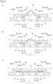
- FIG. 4(a) is a plan view of the viewing window 40 to which the cover member 50 is assembled
- FIG. 4(b) is a cross-sectional view taken along the line A-A in FIG. 4(a) .
- the rotary connector device 1 is configured by assembling a flexible flat cable 100 (hereinafter, referred to as FFC 100) to the rotary connector device body 2.
- FFC 100 flexible flat cable 100
- the rotary connector device body 2 is configured by the rotator 10, the sleeve 30 located below the rotator 10 and assembled with the rotator 10, and the stator 20 assembled by interposing between the rotator 10 and the sleeve 30 so as to relatively rotate.
- the FFC 100 can be accommodated in a housing space S formed inside the rotary connector device body 2 by the rotator 10 and the stator 20.
- the rotator 10 configuring the rotary connector device body 2 is integrally configured by a substantially annular rotating side ring plate 11 having a substantially circular through hole in a central portion in plan view, and an inner peripheral cylinder portion 12 formed downward from an inner peripheral edge of the rotating side ring plate 11.
- the viewing window 40 communicating from outside of the rotary connector device body 2 to the housing space S is provided on a top surface of the rotating side ring plate 11.
- the transparent and flexible cover member 50 is assembled to the viewing window 40 (see FIG. 3 ).
- two rotator-side connectors 13 that rotate integrally with a rotation of the rotator 10 are provided on the top surface of the rotating side ring plate 11.
- the rotator-side connectors 13 are housing portions that house a connection connector attached to one end of the FFC 100 housed in the housing space S.
- a connector of a cable (not shown) connected to an electric circuit of an external device such as a horn switch and an airbag unit disposed on a steering wheel is externally connected to the rotator-side connectors 13.
- the sleeve 30 assembled with the rotator 10 configured as described above is a substantially cylindrical body having a through hole vertically penetrating at a central portion in plan view.
- the sleeve 30 is assembled by vertically interposing a stator 20 to be described later with the rotator 10 and thus allows the rotator 10 and the stator 20 to relatively rotate clockwise and counterclockwise around a central axis of the rotating side ring plate 11 in plan view as a rotation axis.
- the stator 20 rotatable relative to the rotator 10 is a bottomed substantially cylindrical body having an open top surface, and is configured by a fixed side ring plate 21 configuring a bottom surface, and a substantially cylindrical outer peripheral cylinder portion 22 configuring an outer peripheral surface, and two stator-side connector housing portions 23 protruding outward from the stator 20.
- the number of the rotator-side connectors 13 and the number of the stator-side connector housing portions 23 are two. However, the numbers are not limited thereto and can be adjusted as appropriate.
- the fixed side ring plate 21 is an annular plate-like body having an outer diameter slightly larger than an outer diameter of the rotating side ring plate 11 and having a substantially circular through hole in a central portion in plan view.
- the outer peripheral cylinder portion 22 is a cylindrical outer peripheral wall extending upward from an outer peripheral edge of the fixed side ring plate 21.
- Each of the stator-side connector housing portions 23 is a housing portion that houses a connection connector attached to the other end of the FFC 100 housed in the housing space S, and is formed so as to be connectable to an external connector of the combination switch side or an instrument panel side.
- the rotator 10 and the stator 20 configured as described above form the housing space S that houses the FFC 100 by the rotating side ring plate 11 and the inner peripheral cylinder portion 12 and by the fixed side ring plate 21 and the outer peripheral cylinder portion 22.
- the viewing window 40 provided on the top surface of the rotating side ring plate 11, the cover member 50 assembled to the viewing window 40, and the cover member holding portion 60 that holds the cover member 50 against the viewing window 40 will be described on the basis of FIGS. 3 and 4 .
- the viewing window 40 is a rectangular window that vertically penetrates the rotating side ring plate 11.
- the viewing window 40 is formed by longitudinal window frames 41 extending along a longitudinal direction X of the viewing window 40 and transverse window frames 42 extending along a transverse direction Y
- the longitudinal direction of the viewing window 40 is referred to as the longitudinal direction X
- the transverse direction of the viewing window 40 is referred to as the transverse direction Y
- the longitudinal direction X is a tangential direction to a radial direction of the rotating side ring plate 11 at a center of the viewing window 40 in the longitudinal direction X
- the transverse direction Y refers to a direction orthogonal to the longitudinal direction X in plan view.
- an inner side in the longitudinal direction X refers to a direction toward the viewing window 40 along the longitudinal direction X
- an outer side in the longitudinal direction X refers to a direction away from the viewing window 40 along the longitudinal direction X.
- the inner side in the transverse direction Y refers to a radial direction inner side of the rotating side ring plate 11 in the transverse direction Y
- an outer side in the transverse direction Y refers to a radial direction outer side of the rotating side ring plate 11 in the transverse direction Y
- the cover member 50 is a transparent and flexible resin plate-like body, and is configured to have a thickness that is substantially the same as a height between bottom surfaces of outer regulating portions 623 to be described later and the top surface of the rotating side ring plate 11.
- a length of the cover member 50 in the transverse direction Y is configured to be longer than a corresponding length of the viewing window 40, and a length in the longitudinal direction X is sufficiently longer than a distance between connecting portions 611 to be described later.
- the cover member holding portion 60 is configured by inner regulating portions 61 provided in the inner side of the viewing window 40 and an outer holding portion 62 provided in the outer side of the viewing window 40 in the longitudinal direction X.
- the inner regulating portions 61 have a first inner regulating portion 61x and a second inner regulating portion 61y disposed to face each other with respect to the viewing window 40.
- a second shortest distance L2 between the first inner regulating portion 61x and the second inner regulating portion 61y is configured to be shorter than a length L3 of the cover member 50 that faces the second shortest distance L2 when the cover member 50 is disposed at the viewing window 40.
- the inner regulating portions 61 are configured by the connecting portions 611 connecting the longitudinal window frames 41 along the transverse direction Y in the inner side of the viewing window 40, and two inner protrusions 612 protruding from the connecting portions 611 toward the outer side in the longitudinal direction X.
- An inner guide 613 configured by a tapered surface that tapers toward the outer side in the longitudinal direction X is provided on the outer side in the longitudinal direction X of the top surface of the inner protrusions 612.
- the connecting portions 611 are configured to have the same thickness as a thickness of the rotating side ring plate 11. Although the connecting portions 611 have the same thickness as the thickness of the rotating side ring plate 11 in this example, the thickness is not limited thereto but can be changed as appropriate.
- the inner protrusions 612 are convex bodies protruding from the connecting portions 611 toward the outer side in the longitudinal direction X by the same length as a plate width of the connecting portions 611 in plan view.
- the two inner protrusions 612 protrude from the connecting portions 611, and are disposed at positions spaced apart by a predetermined distance from the longitudinal window frames 41 formed on the inner side in transverse direction Y and the outer side in the transverse direction Y, respectively. That is, the two inner protrusions 612 protrude at equal intervals toward the outer side in the longitudinal direction X so as to be line-symmetric with respect to a center line in the longitudinal X of the connecting portions 611 in plan view.
- the outer holding portion 62 is configured by a longitudinal frame 621 formed along the longitudinal direction X at both ends of the viewing window 40 in the transverse direction Y, a transverse frame 622 formed along the transverse direction Y at both ends of the viewing window 40 in the longitudinal direction X, outer regulating portions 623 protruding from a center of the transverse frame 622 toward the inner side in the longitudinal direction X, and three regulating protrusions 624 arranged at equal intervals from an inner end of the outer regulating portions 623 in the longitudinal direction X.
- the outer regulating portions 623 have a first outer regulating portion 623x and a second outer regulating portion 623y that are disposed to face each other with respect to the viewing window 40.
- the first shortest distance L1 between the first outer regulating portion 623x and the second outer regulating portion 623y is configured to be shorter than a length L3 of the cover member 50 that faces the first shortest distance L1 when the cover member 50 is disposed at the viewing window 40.
- the longitudinal frame 621 and the transverse frame 622 are frame bodies erected upward from the top surface of the rotating side ring plate 11 so as to have the same height as the thickness of the rotating side ring plate 11, and are provided so as to surround the viewing window 40 in plan view.
- the longitudinal frame 621 is disposed at both ends in the transverse direction Y with respect to the longitudinal window frames 41 (see FIG. 4(a) ), and the transverse frame 622 is disposed at a position such that an end on the longitudinal direction X is flush with the transverse window frames 42 (see FIG. 4(b) ).
- the rotating side ring plate 11 can be seen on the inner side in the transverse direction Y of the longitudinal frame 621 in plan view.
- the height of the longitudinal frame 621 and the transverse frame 622 is the same as the thickness of the rotating side ring plate 11, but is not limited thereto, and can be adjusted as appropriate.
- each outer regulating portion 623 is a plate-like body protruding from the central portion of the transverse frame 622 toward the inner side in the longitudinal direction X such that top surfaces of the outer regulating portions 623 is flush with the transverse frame 622.
- the thickness of the outer regulating portions 623 is configured to be a length determined by subtracting the thickness of the cover member 50 from the height of the transverse frame 622.
- the length of the outer regulating portions 623 along the transverse direction Y is configured to be substantially the same as the corresponding length of the viewing window 40.
- the thickness and the length in the transverse direction of the outer regulating portions 623 are not limited to the above-described thickness and can be adjusted as appropriate.
- the regulating protrusions 624 are convex portions protruding toward the inner side in the longitudinal direction X from three places of both ends of the outer regulating portions 623 in the transverse direction Y and a central portion in the transverse direction Y, and are disposed along the transverse direction Y at predetermined intervals. Further, an outer guide 625 configured by a tapered surface that tapers toward the outer side in the longitudinal direction X is provided on a bottom surface of each of the regulating protrusions 624 on the inner side in the longitudinal direction X.
- the three regulating protrusions 624 configured as described above are disposed to mesh with the two inner protrusions 612 protruding from the connecting portions 611 disposed to face the outer regulating portions 623 in plan view (see FIG. 4(a) ). Further, tips of the regulating protrusions 624 are disposed on the inner side in the longitudinal direction X with respect to tips of the inner protrusions 612.
- a holding space T that allows the cover member 50 to be inserted and held is formed between the inner regulating portions 61 and the outer regulating portions 623 configured as described above (see FIG. 4(b) ).
- the thickness of the cover member 50 is configured to be the same as a height difference between the bottom surfaces of the outer regulating portions 623 and the top surface of the rotating side ring plate 11.
- the thickness of the cover member 50 is not necessarily required to be this thickness.
- the thickness of the cover member 50 may be smaller than the difference in height between the bottom surfaces of the outer regulating portions 623 and the rotating side ring plate 11.
- the cover member 50 is deflected by applying an external force so as to be convex upward when viewed from the transverse direction Y
- the cover member 50 is disposed such that both ends of the cover member 50 in the longitudinal direction X can be inserted into the holding space T. Since the length of the cover member 50 in the longitudinal direction X is sufficiently longer than the distance between the connecting portions 611, both end sides in the longitudinal direction X of the cover member 50 can be disposed at the position of the holding space T while the cover member 50 is bent.
- the cover member 50 which is restored to a plate-like body by the restoring force F of the cover member 50, is thereby held in the holding space T formed by the inner regulating portions 61, the outer regulating portions 623, and the regulating protrusions 624 (see FIG. 5(c) ).
- the inner regulating portions 61 can regulate a downward movement of the cover member 50.
- the outer regulating portions 623 and the regulating protrusions 624 can regulate an upward movement of the cover member 50.
- both ends of the cover member 50 in the transverse direction Y are held by the rotating side ring plate 11, the cover member 50 can be held in the holding space T more reliably. This allows the cover member 50 to be reliably assembled to the viewing window 40.
- An end face of the cover member 50 on the outer side in the longitudinal direction X and the transverse window frames 42 are not in contact with each other. However, the end face may be in contact with transverse window frames 42 as long as both ends of the cover member 50 are disposed below the outer regulating portions 623 disposed opposite to each other.
- the ends of the cover member 50 deflected by applying an external force so as to be convex upward are disposed at a position where the cover member 50 can be inserted into the holding space T.
- the cover member 50 can be assembled to the viewing window 40 while being held by the cover member holding portion 60 only by releasing the applying external force.
- the rotator 10 the stator 20 are assembled so as to be relatively rotatable in both the clockwise direction and the counterclockwise direction, the rotator 10 being configured by the annular rotating side ring plate 11 and the cylindrical inner peripheral cylinder portion 12 formed on the inner peripheral edge of the rotating side ring plate 11, the stator 20 being configured by the annular fixed side ring plate 21 and the cylindrical outer peripheral cylinder portion 22 formed on the outer peripheral edge of the fixed side ring plate 21.
- the rotary connector device body 2 has the housing space S that can house the FFC 100 therein, and includes the viewing window 40 through which the housing space S can be viewed from outside of the device and that communicates between the housing space S and outside of the device, the transparent and flexible cover member 50 disposed so as to close the viewing window 40, the outer regulating portions 623 and the regulating protrusions 624 that regulate the movement of the cover member 50 toward outside of the device (upward), and the inner regulating portions 61 that regulate the movement of the cover member 50 toward the housing space S (downward).
- the outer regulating portions 623, the regulating protrusions 624, and the inner regulating portions 61 are disposed to face each other with respect to the viewing window 40, the cover member 50 is held in the holding space T formed between the outer regulating portions 623, the regulating protrusions 624, and the inner regulating portions 61, and the length of the cover member 50 in the longitudinal direction X is configured to be longer than the distance between the inner regulating portions 61 disposed to face each other, thereby preventing a reduction in the visibility of the viewing window 40.
- the end sides of the cover member 50 deflected by applying an external force so as to be convex upward are disposed at a position where the cover member 50 can be inserted into the holding space T.
- the cover member 50 is inserted into the holding space T by its own restoring force F, and slides between the inner regulating portions 61, the outer regulating portions 623, and the regulating protrusions 624. The cover member 50 is thereby held in the holding space T.
- the inner regulating portions 61, the outer regulating portions 623, and the regulating protrusions 624 are provided, and the length of the cover member 50 in the longitudinal direction X is configured to be longer than the distance between the inner regulating portions 61 disposed to face each other.
- the cover member 50 can be therefore inserted into the holding space T while being bent, and the inner regulating portions 61, the outer regulating portions 623, and the regulating protrusions 624 can regulate the upward and downward movement of the cover member 50 held in the holding space T while keeping its original plate-like body.
- the cover member 50 can be easily disposed at the viewing window 40 and reliably held against the viewing window 40 only by deflecting the cover member 50 and inserting the deflected cover member 50 into the holding space T.
- an adhesive layer or the like there is no need to use an adhesive layer or the like. Therefore, no foreign matter or dust adheres to an adhesive layer, and a decrease in the visibility of the viewing window 40 can be prevented.
- the cover member 50 can be held only by being inserted into the holding space T, for example, there is no need to apply an adhesive layer to the cover member 50. This can prevent an adhesive attached to the viewing window 40 from becoming cloudy due to deterioration over time and blocking the view.
- the cover member 50 is reliably held against the viewing window 40 as described above, the housing space S can be visually confirmed through the viewing window 40, and a state of the FFC 100 housed in the housing space S can be confirmed. That is, a mark provided on the FFC 100 can be visually recognized, and it can be confirmed whether the rotary connector device 1 housing the FFC 100 in the rotary connector device body 2 is fixed at a neutral position. Further, the cover member 50 is disposed so as to close the viewing window 40, and this can prevent foreign matter from entering the housing space S.
- the inner regulating portions 61, the outer regulating portions 623, and the regulating protrusions 624 are disposed to face each other with respect to the viewing window 40.
- both end sides of the cover member 50 can be inserted into the holding space T.
- the connecting portions 611, the outer regulating portions 623, and the regulating protrusions 624 disposed to face each other can regulate the upward and downward movement of the cover member 50 at both ends of the cover member 50 in the longitudinal direction X.
- the cover member 50 can be held in the holding space T more stably.
- the inner regulating portions 61, the outer regulating portions 623, and the regulating protrusions 624 include the inner guide 613 and the outer guide 625 that guide the cover member 50 to the holding space T.
- the cover member 50 can be guided in the holding space T, and disposed at the viewing window 40 more easily.
- the viewing window 40 is provided on the rotating side ring plate 11, the FFC100 housed in the housing space S can be confirmed even when the rotary connector device 1 in which the FFC 100 is assembled to the rotary connector device body 2 is assembled to a combination switch or the like. That is, it can be confirmed that the rotator 10 assembled to the combination switch or the like is at the neutral position with respect to the stator 20. Therefore, the steering wheel can be securely attached to the rotary connector device 1.
- the cover member 50 assembled to the viewing window 40 is pulled toward outside of the device by applying an external force to the cover member 50 and deflecting the cover member 50 upward.
- the end sides of the cover member 50 can be thus removed from between the inner regulating portions 61, the outer regulating portions 623, and the regulating protrusions 624.
- the cover member 50 can be removed from the viewing window 40.
- the cover member 50 can be easily exchanged by deflecting the cover member 50 to be convex upward and pulling the deflected cover member 50 toward outside of the device.
- the outer holding portion 62 does not need to be erected from the rotating side ring plate 11 toward outside of the device (upward), and the outer holding portion 62 may be erected from the rotating side ring plate 11 toward the housing space S.
- a rotary connector device 1b (rotary connector device body 2b) including a cover member holding portion 70 according to an embodiment of the cover member holding portion 60 will be described on the basis of FIGS. 6 to 10 .
- a configuration of the rotary connector device 1b (rotary connector device body 2b) to be described below that is similar to a configuration of the rotary connector device 1 or the rotary connector device body 2 described above is denoted by the same reference sign, and a description thereof is omitted.
- FIG. 6 is a schematic perspective view of the rotary connector device 1b.
- FIG. 7 is an enlarged view of the portion ⁇ of FIG. 6 in the rotary connector device body 2b.
- FIG. 8 is an explanatory diagram showing a configuration of the cover member holding portion 70.
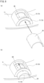
- FIG. 9 is an explanatory view of an assembling method of assembling the cover member 50 to the cover member holding portion 70.
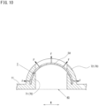
- FIG. 10 is a cross-sectional view taken along the line B-B in FIG. 8(a) .
- FIG. 8(a) is a plan view of the cover member holding portion 70 to which the cover member 50 is assembled.
- FIG. 8(b) is a side view of the cover member holding portion 70 as viewed from the transverse direction Y
- FIG. 8(c) is a cross-sectional view taken along the line C-C in FIG. 8(b) .
- FIG. 9(a) is a schematic perspective view showing a state before the cover member 50 is assembled to the cover member holding portion 70.
- FIG. 9(b) is a schematic perspective view showing the cover member 50 is being assembled to the cover member holding portion 70.
- the rotating side ring plate 11 of the rotary connector device body 2b is provided with the viewing window 40, and the cover member holding portion 70 that holds the cover member 50 against the viewing window 40.
- the cover member holding portion 70 is formed at a location corresponding to the viewing window 40, and is a substantially cylindrical body having a semicircular bottom surface provided with a through hole vertically penetrating at a location corresponding to the viewing window 40.
- the cover member holding portion 70 is configured by arc-shaped inner regulating portions 71 and an arc-shaped outer regulating portion 72 that is a cylindrical body covering the outer periphery of the arc-shaped inner regulating portions 71.
- each of the arc-shaped inner regulating portions 71 is a cylindrical body that has a semicircular bottom surface being convex upward and having a longer diameter than a length of the viewing window 40 in the longitudinal direction X and that has a height extending along the transverse direction Y
- Each of the arc-shaped inner regulating portions 71 is provided with a through hole vertically penetrating at a location corresponding to the viewing window 40.
- an inner arc guide 73 configured by a tapered surface tapering toward the viewing window 40 is provided on a top surface of each arc-shaped inner regulating portion 71 on both ends in the transverse direction Y
- the arc-shaped outer regulating portion 72 is a cylindrical body that has a semi-annular bottom surface whose inner periphery has a diameter larger by the thickness of the cover member 50 than the diameter of the arc-shaped inner regulating portions 71, and that has a height extending along the transverse direction Y
- the arc-shaped outer regulating portion 72 is provided with a through hole vertically penetrating in a portion corresponding to the viewing window 40 in plan view.
- an outer arc guide 74 configured by a tapered surface tapering toward the viewing window 40 is provided on a lower surface of the arc-shaped outer regulating portion 72 on both ends in the transverse direction Y.
- the length of the arc-shaped inner regulating portions 71 and the arc-shaped outer regulating portion 72 in the transverse direction Y is longer than the corresponding length of the viewing window 40 in the transverse direction Y
- a holding space T having the same distance as the plate thickness of the cover member 50 is formed between the arc-shaped outer regulating portion 72 and the arc-shaped inner regulating portions 71 in the transverse direction Y
- An arc-shaped insertion hole G through which the cover member 50 can be inserted is formed on both ends in the transverse direction Y of each arc-shaped inner regulating portion 71 and the arc-shaped outer regulating portion 72.
- the cover member 50 which is deflected upward by applying an external force to be in a semicircular tubular shape convex, is inserted through the insertion hole G from the outer side in the transverse direction Y to the inner side in the transverse direction Y (see FIG. 9(a) ).
- the cover member 50 can be held in the holding space T by being pushed in the transverse direction Y (see FIG.9 (b) ), and the cover member 50 can be assembled to the cover member holding portion 70.
- the cover member 50 incorporated in the cover member holding portion 70 as described above is released from the external force deflecting the cover member 50 into a tubular shape.
- the restoring force F to return the cover member 50 to the original plate-like body is applied to the cover member 50.
- the cover member 50 is pressed against an inner peripheral surface of the arc-shaped outer regulating portion 72 by the restoring force F.
- a frictional force is thus generated between the cover member 50 and the inner peripheral surface of the arc-shaped outer regulating portion 72.
- the cover member 50 is therefore fixed by the cover member holding portion 70 (see FIG. 10 ).
- the restoring force F applied to the cover member 50 locks the cover member 50 to the cover member holding portion 70.
- the cover member 50 thereby reliably closes the viewing window 40 and is held against the viewing window 40.
- the rotator 10 and the stator 20 are assembled so as to be relatively rotatable in both the clockwise direction and the counterclockwise direction, the rotator 10 being configured by the annular rotating side ring plate 11 and the cylindrical inner peripheral cylinder portion 12 formed on the inner peripheral edge of the rotating side ring plate 11, the stator 20 being configured by the annular fixed side ring plate 21 and the cylindrical outer peripheral cylinder portion 22 formed on the outer peripheral edge of the fixed side ring plate 21.
- the rotary connector device 1b has the housing space S that can house the FFC 100 therein, and includes the viewing window 40 through which the housing space S can be viewed from outside of the device and that communicates between the housing space S and outside of the device, the transparent and flexible cover member 50 disposed so as to close the viewing window 40, the arc-shaped outer regulating portion 72 that regulates the movement of the cover member 50 toward outside of the device, and the arc-shaped inner regulating portions 71 that regulate the movement of the cover member 50 toward the housing space S.
- the arc-shaped inner regulating portions 71 and the arc-shaped outer regulating portion 72 are disposed to face each other with respect to the viewing window 40, the cover member 50 is held in the holding space T formed between the arc-shaped inner regulating portions 71 and the arc-shaped outer regulating portion 72, and the length of the cover member 50 in the longitudinal direction X is configured to be longer than the distance between the arc-shaped inner regulating portions 71 disposed to face each other. Therefore, the rotary connector device 1b has a similar effect as the rotary connector device 1 according to the first example.
- the arc-shaped outer regulating portion 72 is configured to hold the cover member 50 in an arc shape protruding upward. This generates a restoring force F applied toward a radial outer side of the arc shape of the flexible cover member 50, that is, from a bottom surface toward a top surface of the cover member 50.
- the arc-shaped outer regulating portion 72 is configured to hold the shape of the cover member 50 in an arc shape, the external force that holds the arc shape is applied to the cover member 50 spreading upward due to the restoring force F in a direction opposite to a direction in which the restoring force F is applied. Therefore, the frictional force is generated between the cover member 50 and the arc-shaped outer regulating portion 72.
- the cover member 50 is fixed to the viewing window 40 while maintaining its shape by the arc-shaped outer regulating portion 72. This can prevent the cover member 50 from coming off from the viewing window 40 and prevent foreign matter from entering the inside of the housing space S even when an unexpected external force is applied to the cover member 50.
- the cover member 50 which is formed in a circular arc that is convex upward, has the restoring force F applied from the bottom surface toward the top surface of the cover member 50. Therefore, the cover member 50 can be suppressed from entering the housing space S side even when a downward external force is applied to the cover member 50.
- the arc-shaped outer regulating portion 72 regulates the movement of the cover member 50 toward outside of the device, and thus the cover member 50 can be prevented from easily coming off. Even if the cover member 50 comes off, the cover member 50 comes off upward. This can suppress the cover member 50 from entering the housing space S side.
- the inner arc guide 73 and the outer arc guide 74 are formed in the arc-shaped inner regulating portions 71 and the arc-shaped outer regulating portion 72, respectively.
- the cover member 50 can be easily guided to the insertion hole G, and the cover member 50 can be easily disposed at the viewing window 40.
- the arc-shaped outer regulating portion 72 which is locked by utilizing the restoring force F of the cover member 50, can reliably lock the cover member 50 to the cover member holding portion 70.
- the cover member 50 can be stably held against the viewing window 40 and fixed to the viewing window 40. This can prevent the cover member 50 from coming off.
- the arc-shaped outer regulating portion 72 is provided in the direction in which the restoring force F is applied at the position of the cover member 50 to be locked.
- the cover member 50 can be thus locked by utilizing the restoring force F of the flexible cover member 50. Therefore, the cover member 50 can be locked with a simple configuration.
- the present invention is not limited to only the configuration of the above embodiment but can obtain multiple embodiments.
- the viewing window 40 is provided on the rotating side ring plate 11, but the arrangement position of the viewing window 40 is not limited as long as the housing space S can be visually confirmed from outside of the device.
- the viewing window 40 may be disposed, for example, on the fixed side ring plate 21, the inner peripheral cylinder portion 12, the outer peripheral cylinder portion 22, or at a corner formed by the rotating side ring plate 11 and the inner peripheral cylinder portion 12.
- the shape of the viewing window 40 is not particularly limited, but may be varied as a rectangle, a polygon, a circle, an ellipse, a fan, or the like.
- the inner regulating portions 61 and the arc-shaped inner regulating portion 71 are provided along the transverse direction Y in the first example and the embodiment, but may be provided along the longitudinal direction X, and may be provided in a direction intersecting with the longitudinal direction X.
- a pair of inner regulating portions 61 and outer regulating portions 623, the arc-shaped inner regulating portion 71 and the arc-shaped outer regulating portion 72, and the like are disposed to face each other with respect to the viewing window 40.
- the number of the inner regulating portions 61 may be one, and the number of the outer regulating portions 623 may be one.
- the cover member 50 is formed in a flat plate shape and disposed with respect to the viewing window 40.
- the cover member 50 may be formed in an arc shape.
- FIGS. 11 and 12 illustrate a cover member holding portion 60c and a cover member holding portion 60d, respectively, according to examples other than the first example.
- FIG. 11(a) is a plan view of the viewing window 40 according to another example.
- FIG. 11(b) is a cross-sectional view taken along the line E-E in FIG. 11(a) before the cover member 50 is held in the holding space T.
- FIG. 11(c) is a cross-sectional view taken along the line E-E while the cover member 50 is held.
- FIG. 12(a) is a plan view of the viewing window 40 in an example different from FIG. 11 .
- FIG. 12(b) is a cross-sectional view taken along the line F-F in FIG. 12(a) while the cover member 50 is held.
- a top surface of an inner regulating portion 61c corresponding to the inner regulating portions 61 is formed in an arc shape having a predetermined curvature.
- a bottom surface of an outer regulating portion 623c corresponding to the outer regulating portions 623 is formed in an arc shape having a predetermined curvature.
- the outer regulating portion 623c and the inner regulating portion 61c are disposed in that order from the outer side in the longitudinal direction X to the inner side in the longitudinal direction X (see FIGS 11(a) and 11(b) ).
- each longitudinal window frame 41 a protrusion 67c protruding toward the inner side in the longitudinal direction X is provided on a lower end of each longitudinal window frame 41.
- the cover member holding portion 60c configured as described above can hold the cover member 50 in the holding space T by inserting, into the holding space T, the cover member 50 deflected by applying an external force to be convex upward and then releasing the external force.
- the top surface of the cover member 50 contacts the outer regulating portion 623c, and the bottom surface of the cover member 50 contacts the inner regulating portion 61c. Further, both end sides of the cover member 50 on the outer side in the longitudinal direction X are locked by transverse window frames 42c functioning as locking portions. The cover member 50 is therefore held in the holding space T while kept in an arc shape that is convex upward (see FIG. 10(c)).
- the curvatures of the inner regulating portion 61c and the outer regulating portion 623c may be the same curvature. However, when the curvature of the inner regulating portion 61c is larger than the curvature of the outer regulating portion 623c, the inner regulating portion 61c and the outer regulating portion 623c can grip the cover member 50 to reliably fix the cover member 50.
- a top surface of an inner regulating portion 61d corresponding to the inner regulating portions 61 is formed in an arc shape having a predetermined curvature.
- a bottom surface of an outer regulating portion 623d corresponding to the outer regulating portions 623 is formed in an arc shape having a predetermined curvature.
- the outer regulating portion 623d and the inner regulating portion 61d are disposed in that order from the outer side in the longitudinal direction Xto the inner side in the longitudinal direction X.
- the outer regulating portion 623d protrudes from the transverse window frames 42 toward the viewing window 40, but does not connect the transverse window frames 42 to each other (see FIG. 12(a) ).
- the cover member 50 disposed through the holding space T is formed in an arc shape protruding downward.
- the top surface of the cover member 50 contacts the outer regulating portion 623d and the bottom surface of the cover member 50 contacts the inner regulating portion 61d due to the restoring force of the cover member 50.
- both end sides of the cover member 50 on the outer side in the longitudinal direction X are locked by the transverse window frames 42 functioning as locking portions, and thus the cover member 50 is held in the holding space T.
- the curvatures of the inner regulating portion 61d and the outer regulating portion 623d may be the same curvature. However, when the curvature of the outer regulating portion 623d is larger than the curvature of the inner regulating portion 61d, the inner regulating portion 61d and the outer regulating portion 623c can grip the cover member 50 to reliably fix the cover member 50.
Landscapes
- Engineering & Computer Science (AREA)
- Mechanical Engineering (AREA)
- Chemical & Material Sciences (AREA)
- Combustion & Propulsion (AREA)
- Transportation (AREA)
- Power Engineering (AREA)
- Steering Controls (AREA)
- Details Of Connecting Devices For Male And Female Coupling (AREA)
- Connector Housings Or Holding Contact Members (AREA)
- Manufacturing Of Electrical Connectors (AREA)
Description
- The present invention relates to a rotary connector device mounted on a vehicle body such as an automobile, and a method of assembling the rotary connector device.
- A rotary connector device mounted on a vehicle such as an automobile is mainly configured such that a fixed body fixed to a vehicle body and a rotating body to which a steering wheel is mounted are coaxially assembled so as to be relatively rotatable. In a housing space formed by the fixed body and the rotating body, a flexible flat cable (hereinafter referred to as FFC) is housed so as to be able to be fastened and unwound following a rotation of the steering wheel.
- In this rotary connector device, when the rotary connector device is assembled to a vehicle body or a steering wheel is assembled, the rotating body relatively rotates with respect to the fixed body, and the rotary connector device may come off from a neutral position. In this case, the FFC is wound in an unbalanced manner. In a case where the rotary connector device and the steering wheel are assembled while the neutral position of the rotary connector device and a neutral position in a rotational direction of the steering wheel are deviated as described above, the FFC is not sufficiently long for the steering wheel to be rotated by a desired number of rotations when the steering wheel is steered in a predetermined rotational direction.
- In order to solve such a problem, various rotary connector devices that can confirm whether the rotary connector devices are at a neutral position have been proposed. For example,
JP 2010-146943 A - According to the rotary connector device disclosed in
JP 2010-146943 A - However, since the transparent cover member is provided with the adhesive layer, foreign matter and dust may adhere to the adhesive layer before attaching the cover member to the viewing window, and visibility of the viewing window may be reduced.
-
JP 2006-217730 A -
JP S61-164079 U -
JP 2007-136017 A - The present invention is defined by the independent claims. The dependent claims concern optional features of some embodiments of the invention. Due account shall be taken of any element which is equivalent to an element specified in the claims.
- An object of the present invention is to provide a rotary connector device and a method of assembling the rotary connector device that can prevent a reduction in visibility of a viewing window in view of the above-described problem.
- The present invention is a rotary connector device according to
claim 1, the rotary connector device comprising a rotating body and a fixed body assembled so as to be relatively rotatable, the rotating body having a rotating side ring plate in an annular shape and an inner peripheral cylinder portion in a cylindrical shape that is formed at an inner peripheral edge of the rotating side ring plate, the fixed body having a fixed side ring plate in an annular shape and an outer peripheral cylinder portion in a cylindrical shape that is formed at an outer peripheral edge of the fixed side ring plate, and having a housing space inside, the rotary connector device including a viewing window that is a through hole through which the housing space is viewable from outside of the rotary connector device, a cover member disposed at the viewing window so as to cover the viewing window and being transparent and flexible, an arc-shaped outer regulating portion facing toward outside of the rotary connector device and disposed so as to contact an outer surface of the cover member, and an arc-shaped inner regulating portion facing the housing space and disposed so as to be able to contact an inner surface of the cover member, in which the cover member is configured to be held in a holding space between the arc-shaped outer regulating portion and the arc-shaped inner regulating portion, wherein an arc-shaped insertion hole through which the cover member can be inserted is formed on both ends in a first direction of each of the arc-shaped outer regulating portion and the arc-shaped inner regulating portion, wherein the first direction is one of a transverse direction, a longitudinal direction, or a direction intersecting with the longitudinal direction, wherein the longitudinal direction is a longitudinal direction of the viewing window, and the transverse direction is a transverse direction of the viewing window, and wherein the arc-shaped insertion hole is configured so as to allow the cover member to be inserted into the holding space by inserting the cover member into the arc-shaped insertion hole and pushing the cover member in the first direction so that the cover member is configured to be fixed in the viewing window while maintaining its shape by the arc-shaped outer regulating portion. - Further, the present invention is a method of assembling a rotary connector device according to
claim 10, the method including the steps of assembling a rotating body and a fixed body to be relatively rotatable so as to have a housing space inside, providing a viewing window that is a through hole through which the housing space is viewable from outside of the rotary connector device, providing an arc-shaped outer regulating portion and an arc-shaped inner regulating portion on a periphery of the viewing window, and passing a cover member that is transparent and flexible through an arc-shaped insertion hole while being deflected to arrange the cover member in a holding space between the arc-shaped outer regulating portion and the arc-shaped inner regulating portion so as to cover the viewing window, wherein arc-shaped the insertion hole is formed on both ends in a first direction of each of the arc-shaped outer regulating portion and the arc-shaped inner regulating portion, wherein the first direction is one of a transverse direction, a longitudinal direction, or a direction intersecting with the longitudinal direction, and wherein passing the cover member through the arc-shaped insertion hole comprises inserting the cover member into the arc-shaped insertion hole and pushing the cover member in the first direction so that the cover member is fixed in the viewing window while maintaining its shape by the arc-shaped outer regulating portion. - An arrangement position of the viewing window is not limited as long as the housing space can be visually confirmed from outside of the device. The viewing window may be disposed, for example, on the rotating side ring plate, the fixed side ring plate, the inner peripheral cylinder portion, the outer peripheral cylinder portion, or at a corner formed by the rotating side ring plate and the inner peripheral cylinder portion.
- A shape of the viewing window is not particularly limited, but includes various shapes such as a rectangle, a polygon, a circle, and an ellipse.
- The cover member only needs to have a configuration in which the neutral position of the FFC can be confirmed from the viewing window, including a configuration that covers the viewing window, and a configuration that is fitted into and closes the viewing window.
- In some embodiments, the outer regulating portion and the inner regulating portion may include a configuration to regulate a movement of the cover member by contacting the outer regulating portion and the inner regulating portion, a configuration to regulate the movement of the cover member by interposing the cover member between the outer regulating portion and the inner regulating portion, and a configuration to regulate the movement of the cover member by arranging the outer regulating portion and the inner regulating portion apart from the cover member and interfering with the cover member moved by, for example, vibration or the like.
- Further, the above description that at least one of the outer regulating portion or the inner regulating portion is disposed to face each other means, for example, that two independent outer regulating portions or two independent inner regulating portions face each other, or that one outer regulating portion or one inner regulating portion is provided along a circumferential direction of the viewing window and parts of the outer regulating portion or the inner regulating portion are disposed to face each other. That is, the number of the outer regulating portion or the inner regulating portion is not necessarily limited to plural.
- The present invention can prevent a reduction in visibility of the viewing window.
- Specifically, according to the method of the present invention, the cover member is inserted into the holding space while being deflected, and the cover member can be therefore disposed at a predetermined position with respect to the viewing window. Then, the cover member comes into contact with the outer regulating portion or the like forming the holding space by a restoring force of the cover member generated by releasing an external force applied to the cover member, and thus the cover member can be held in the holding space.
- In addition, the cover member includes the outer regulating portion and the inner regulating portion, and a corresponding dimension of the cover member may be configured to be longer than a distance between at least one of the outer regulating portion or the inner regulating portion disposed to face each other. Thus, the movement of the cover member held in the holding space toward outside of the device and toward the housing space can be regulated. The cover member can be therefore reliably assembled to the viewing window.
- In this way, the cover member can be disposed at the viewing window and securely held at the viewing window only by inserting the deflected cover member into the holding space. Thus, there is no need to apply an adhesive layer to the cover member before attaching the cover member to the viewing window. This can prevent a reduction in the visibility of the viewing window due to foreign matter and dust adhering to the adhesive layer. Further, since the cover member can be disposed at the viewing window only by deflecting the cover member and inserting the deflected cover member into the holding space, this operation can be performed reliably and quickly.
- As an aspect of embodiments of the present invention, both the outer regulating portion and the inner regulating portion may be configured as a pair disposed to face each other with respect to the viewing window.
- As an aspect of embodiments of the present invention, the holding space is formed as a pair at positions disposed to face each other with respect to the viewing window. Thus, both end sides of the cover member can be inserted into the holding space. The outer regulating portion or the inner regulating portion disposed to face each other can regulate the movement of the cover member toward outside of the device and toward the housing space. The cover member can be therefore stably held in the holding space.
- Further, as an aspect of embodiments of the present invention, the outer regulating portion may be configured to hold the cover member in an arc shape protruding in a communication direction of the viewing window.
- The term "protruding in a communication direction of the viewing window" includes a case where a projection is convex toward outside of the device and a case where a projection is concave.
- In some embodiments, the outer regulating portion and the inner regulating portion have a continuous or discontinuous arc shape, or a configuration in which the outer regulating portion and the inner regulating portion are formed in an arc shape such that the holding space formed between the outer regulating portion and the inner regulating portion is an arc shape.
- According to embodiments of the present invention, since the flexible cover member can be formed in an arc shape, the restoring force is generated on the cover member toward a radial outer side of the arc shape. Meanwhile, since the arc-shaped outer regulating portion is configured to hold the shape of the cover member in an arc shape, a part of the cover member spreading toward the radial outer side due to the restoring force interferes with the arc-shaped outer regulating portion. As a result, a frictional force is generated between the cover member and the arc-shaped outer regulating portion. The cover member is thus held by the arc-shaped outer regulating portion.
- Specifically, in a case where an arc-shaped groove is formed protruding toward outside of the device by the outer regulating portion and the inner regulating portion, the flat plate-shaped cover member is formed in an arc shape. As a result, the restoring force toward outside of the device is generated at the cover member.
- On the other hand, since the arc-shaped outer regulating portion holds the cover member in an arc shape, the cover member is pressed against the arc-shaped outer regulating portion by the restoring force. Thus, the frictional force is generated between the cover member and the arc-shaped outer regulating portion. Thus, the cover member is fixed to the viewing window while being held by the arc-shaped outer regulating portion. This can prevent the cover member from coming off from the viewing window even when an external force due to, for example, vibration is applied to the cover member, and can prevent foreign matter from entering the housing space.
- Further, as an aspect of the present invention, in the holding space, the cover member may be formed in an arc shape protruding toward outside of the device.
- According to embodiments of this invention, even when an external force is applied to the cover member, the cover member can be prevented from entering the housing space.
- Specifically, the cover member, which is formed in a convex shape toward outside of the device, has the restoring force toward outside of the device. This can prevent the cover member from entering the housing space side even when an external force is applied to the cover member from outside of the device.
- Meanwhile, according to embodiments of the present invention, when an external force is applied to the cover member from the housing space side, the movement of the cover member toward outside of the device is regulated by the outer regulating portion, thereby preventing the cover member from easily coming off. Further, even when the cover member comes off, the cover member comes off toward outside of the device, and thus the cover member can be prevented from entering the housing space.
- Further, according to embodiments of the present invention, when the viewing window is provided on the rotating side ring plate, the cover member, which is formed in an upward convex shape, hardly retains foreign matter such as dust. This can prevent a reduction in the visibility of the visual window.
- Further, as an aspect of embodiments of the present invention, a guide portion that guides the cover member to the holding space may be formed by the outer regulating portion and the inner regulating portion.
- According to the present invention, the cover member, which is guided to the holding space, can be more easily disposed at the viewing window.
- Further, as an aspect of embodiments of the present invention, a locking portion that locks the cover member may be provided.
- According to embodiments of the present invention, the cover member can be locked to the viewing window. Thus, the cover member can be stably held and prevented from coming off. The locking portion includes, for example, a configuration using the restoring force of the cover member, and a configuration in which the cover member is provided with the locking portion separately.
- Further, as an aspect of embodiments of the present invention, the locking portion may be provided in a direction in which the restoring force is applied at a position of the cover member to be locked.
- According to embodiments of the present invention, the cover member can be locked by utilizing the restoring force of the flexible cover member. Thus, the cover member can be locked with a simple configuration.
- Further, as an aspect of embodiments of the present invention, the viewing window may be provided on the rotating side ring plate.
- According to embodiments of the present invention, the FFC housed in the housing space can be confirmed even when the rotary connector device is assembled to a combination switch or the like. That is, the neutral position of the rotating body in an assembled state can be confirmed.
- According to the present invention, a rotary connector device and a method of assembling the rotary connector device capable of preventing a reduction in visibility of a viewing window can be provided.
-
-
FIG. 1 is a schematic perspective view of a rotary connector device according to a first embodiment. -
FIG. 2 is a schematic exploded perspective view of the rotary connector device according to a non-claimed first example which is useful for understanding the present invention. -
FIG. 3 is an enlarged schematic perspective view of a portion α inFIG. 2 . -
FIG. 4 is an explanatory diagram of a cover member holding portion that holds a cover member against a viewing window in the first example. -
FIG.5 is an explanatory diagram of an assembling method of assembling the cover member to the viewing window in the first example. -
FIG. 6 is a schematic perspective view of a rotary connector device according to an embodiment. -
FIG. 7 is an enlarged schematic perspective view of a portion α in the embodiment. -
FIG. 8 is an explanatory diagram of a cover member holding portion in the embodiment. -
FIG. 9 is an explanatory diagram of an assembling method of assembling a cover member to a viewing window in the embodiment. -
FIG. 10 is an explanatory diagram of the cover member being assembled to the viewing window in the embodiment. -
FIG. 11 is an explanatory diagram of a cover member holding portion in a non-claimed second example which is useful for understanding the present invention. -
FIG. 12 is an explanatory diagram of a cover member holding portion in a non-claimed third example which is useful for understanding the present invention. - A rotary
connector device body 2 and an assembling method of assembling acover member 50 to aviewing window 40 provided in the rotaryconnector device body 2 according to a first example of the present invention will be described with reference toFIGS. 1 to 5(c) . -
FIG. 1 is a schematic perspective view of therotary connector device 1, andFIG. 2 is a schematic exploded perspective view of therotary connector device 1. Here, a direction of arotator 10 with respect to astator 20 is upward, and a direction of asleeve 30 with respect to thestator 20 is downward. -
FIG. 3 is an enlarged schematic perspective view of a portion α inFIG. 2 .FIG. 4 is an explanatory diagram of a covermember holding portion 60 that holds thecover member 50 against theviewing window 40.FIG. 5 is an explanatory diagram of the assembling method of assembling thecover member 50 to theviewing window 40. - Specifically,
FIG. 4(a) is a plan view of theviewing window 40 to which thecover member 50 is assembled, andFIG. 4(b) is a cross-sectional view taken along the line A-A inFIG. 4(a) . - The
rotary connector device 1 is configured by assembling a flexible flat cable 100 (hereinafter, referred to as FFC 100) to the rotaryconnector device body 2. - As shown in
FIGS. 1 and2 , the rotaryconnector device body 2 is configured by therotator 10, thesleeve 30 located below therotator 10 and assembled with therotator 10, and thestator 20 assembled by interposing between therotator 10 and thesleeve 30 so as to relatively rotate. TheFFC 100 can be accommodated in a housing space S formed inside the rotaryconnector device body 2 by therotator 10 and thestator 20. - As shown in
FIG. 2 , therotator 10 configuring the rotaryconnector device body 2 is integrally configured by a substantially annular rotatingside ring plate 11 having a substantially circular through hole in a central portion in plan view, and an innerperipheral cylinder portion 12 formed downward from an inner peripheral edge of the rotatingside ring plate 11. - The
viewing window 40 communicating from outside of the rotaryconnector device body 2 to the housing space S is provided on a top surface of the rotatingside ring plate 11. The transparent andflexible cover member 50 is assembled to the viewing window 40 (seeFIG. 3 ). - In addition, two rotator-
side connectors 13 that rotate integrally with a rotation of therotator 10 are provided on the top surface of the rotatingside ring plate 11. The rotator-side connectors 13 are housing portions that house a connection connector attached to one end of theFFC 100 housed in the housing space S. A connector of a cable (not shown) connected to an electric circuit of an external device such as a horn switch and an airbag unit disposed on a steering wheel is externally connected to the rotator-side connectors 13. - As shown in
FIG. 2 , thesleeve 30 assembled with therotator 10 configured as described above is a substantially cylindrical body having a through hole vertically penetrating at a central portion in plan view. Thesleeve 30 is assembled by vertically interposing astator 20 to be described later with therotator 10 and thus allows therotator 10 and thestator 20 to relatively rotate clockwise and counterclockwise around a central axis of the rotatingside ring plate 11 in plan view as a rotation axis. - The
stator 20 rotatable relative to therotator 10 is a bottomed substantially cylindrical body having an open top surface, and is configured by a fixedside ring plate 21 configuring a bottom surface, and a substantially cylindrical outerperipheral cylinder portion 22 configuring an outer peripheral surface, and two stator-sideconnector housing portions 23 protruding outward from thestator 20. - In this example, the number of the rotator-
side connectors 13 and the number of the stator-sideconnector housing portions 23 are two. However, the numbers are not limited thereto and can be adjusted as appropriate. - The fixed
side ring plate 21 is an annular plate-like body having an outer diameter slightly larger than an outer diameter of the rotatingside ring plate 11 and having a substantially circular through hole in a central portion in plan view. - The outer
peripheral cylinder portion 22 is a cylindrical outer peripheral wall extending upward from an outer peripheral edge of the fixedside ring plate 21. - Each of the stator-side
connector housing portions 23 is a housing portion that houses a connection connector attached to the other end of theFFC 100 housed in the housing space S, and is formed so as to be connectable to an external connector of the combination switch side or an instrument panel side. - The
rotator 10 and thestator 20 configured as described above form the housing space S that houses theFFC 100 by the rotatingside ring plate 11 and the innerperipheral cylinder portion 12 and by the fixedside ring plate 21 and the outerperipheral cylinder portion 22. - Next, the
viewing window 40 provided on the top surface of the rotatingside ring plate 11, thecover member 50 assembled to theviewing window 40, and the covermember holding portion 60 that holds thecover member 50 against theviewing window 40 will be described on the basis ofFIGS. 3 and4 . - As shown in
FIGS. 3 and4 , theviewing window 40 is a rectangular window that vertically penetrates the rotatingside ring plate 11. Theviewing window 40 is formed bylongitudinal window frames 41 extending along a longitudinal direction X of theviewing window 40 andtransverse window frames 42 extending along a transverse direction Y - Here, the longitudinal direction of the
viewing window 40 is referred to as the longitudinal direction X, and the transverse direction of theviewing window 40 is referred to as the transverse direction Y The longitudinal direction X is a tangential direction to a radial direction of the rotatingside ring plate 11 at a center of theviewing window 40 in the longitudinal direction X. The transverse direction Y refers to a direction orthogonal to the longitudinal direction X in plan view. - Further, an inner side in the longitudinal direction X refers to a direction toward the
viewing window 40 along the longitudinal direction X, and an outer side in the longitudinal direction X refers to a direction away from theviewing window 40 along the longitudinal direction X. The inner side in the transverse direction Y refers to a radial direction inner side of the rotatingside ring plate 11 in the transverse direction Y, and an outer side in the transverse direction Y refers to a radial direction outer side of the rotatingside ring plate 11 in the transverse direction Y - The
cover member 50 is a transparent and flexible resin plate-like body, and is configured to have a thickness that is substantially the same as a height between bottom surfaces of outer regulatingportions 623 to be described later and the top surface of the rotatingside ring plate 11. A length of thecover member 50 in the transverse direction Y is configured to be longer than a corresponding length of theviewing window 40, and a length in the longitudinal direction X is sufficiently longer than a distance between connectingportions 611 to be described later. - As shown in
FIGS. 3 and4 , the covermember holding portion 60 is configured byinner regulating portions 61 provided in the inner side of theviewing window 40 and an outer holdingportion 62 provided in the outer side of theviewing window 40 in the longitudinal direction X. - The
inner regulating portions 61 have a first inner regulatingportion 61x and a second inner regulatingportion 61y disposed to face each other with respect to theviewing window 40. A second shortest distance L2 between the first inner regulatingportion 61x and the second inner regulatingportion 61y is configured to be shorter than a length L3 of thecover member 50 that faces the second shortest distance L2 when thecover member 50 is disposed at theviewing window 40. - As shown in
FIG. 4 , theinner regulating portions 61 are configured by the connectingportions 611 connecting thelongitudinal window frames 41 along the transverse direction Y in the inner side of theviewing window 40, and twoinner protrusions 612 protruding from the connectingportions 611 toward the outer side in the longitudinal direction X. Aninner guide 613 configured by a tapered surface that tapers toward the outer side in the longitudinal direction X is provided on the outer side in the longitudinal direction X of the top surface of theinner protrusions 612. The connectingportions 611 are configured to have the same thickness as a thickness of the rotatingside ring plate 11. Although the connectingportions 611 have the same thickness as the thickness of the rotatingside ring plate 11 in this example, the thickness is not limited thereto but can be changed as appropriate. - The
inner protrusions 612 are convex bodies protruding from the connectingportions 611 toward the outer side in the longitudinal direction X by the same length as a plate width of the connectingportions 611 in plan view. The twoinner protrusions 612 protrude from the connectingportions 611, and are disposed at positions spaced apart by a predetermined distance from thelongitudinal window frames 41 formed on the inner side in transverse direction Y and the outer side in the transverse direction Y, respectively. That is, the twoinner protrusions 612 protrude at equal intervals toward the outer side in the longitudinal direction X so as to be line-symmetric with respect to a center line in the longitudinal X of the connectingportions 611 in plan view. - As shown in
FIGS. 3 and4 , the outer holdingportion 62 is configured by alongitudinal frame 621 formed along the longitudinal direction X at both ends of theviewing window 40 in the transverse direction Y, atransverse frame 622 formed along the transverse direction Y at both ends of theviewing window 40 in the longitudinal direction X, outer regulatingportions 623 protruding from a center of thetransverse frame 622 toward the inner side in the longitudinal direction X, and three regulatingprotrusions 624 arranged at equal intervals from an inner end of the outer regulatingportions 623 in the longitudinal direction X. - The
outer regulating portions 623 have a firstouter regulating portion 623x and a second outer regulatingportion 623y that are disposed to face each other with respect to theviewing window 40. The first shortest distance L1 between the firstouter regulating portion 623x and the second outer regulatingportion 623y is configured to be shorter than a length L3 of thecover member 50 that faces the first shortest distance L1 when thecover member 50 is disposed at theviewing window 40. - As shown in
FIG. 4 , thelongitudinal frame 621 and thetransverse frame 622 are frame bodies erected upward from the top surface of the rotatingside ring plate 11 so as to have the same height as the thickness of the rotatingside ring plate 11, and are provided so as to surround theviewing window 40 in plan view. - Specifically, the
longitudinal frame 621 is disposed at both ends in the transverse direction Y with respect to the longitudinal window frames 41 (seeFIG. 4(a) ), and thetransverse frame 622 is disposed at a position such that an end on the longitudinal direction X is flush with the transverse window frames 42 (seeFIG. 4(b) ). Thus, the rotatingside ring plate 11 can be seen on the inner side in the transverse direction Y of thelongitudinal frame 621 in plan view. - Note that the height of the
longitudinal frame 621 and thetransverse frame 622 is the same as the thickness of the rotatingside ring plate 11, but is not limited thereto, and can be adjusted as appropriate. - As shown in
FIG.4(b) , each outer regulatingportion 623 is a plate-like body protruding from the central portion of thetransverse frame 622 toward the inner side in the longitudinal direction X such that top surfaces of the outer regulatingportions 623 is flush with thetransverse frame 622. The thickness of the outer regulatingportions 623 is configured to be a length determined by subtracting the thickness of thecover member 50 from the height of thetransverse frame 622. - Further, the length of the outer regulating
portions 623 along the transverse direction Y is configured to be substantially the same as the corresponding length of theviewing window 40. - Note that the thickness and the length in the transverse direction of the outer regulating
portions 623 are not limited to the above-described thickness and can be adjusted as appropriate. - The regulating
protrusions 624 are convex portions protruding toward the inner side in the longitudinal direction X from three places of both ends of the outer regulatingportions 623 in the transverse direction Y and a central portion in the transverse direction Y, and are disposed along the transverse direction Y at predetermined intervals. Further, anouter guide 625 configured by a tapered surface that tapers toward the outer side in the longitudinal direction X is provided on a bottom surface of each of the regulatingprotrusions 624 on the inner side in the longitudinal direction X. - The three regulating
protrusions 624 configured as described above are disposed to mesh with the twoinner protrusions 612 protruding from the connectingportions 611 disposed to face the outer regulatingportions 623 in plan view (seeFIG. 4(a) ). Further, tips of the regulatingprotrusions 624 are disposed on the inner side in the longitudinal direction X with respect to tips of theinner protrusions 612. - A holding space T that allows the
cover member 50 to be inserted and held is formed between theinner regulating portions 61 and the outer regulatingportions 623 configured as described above (seeFIG. 4(b) ). - In this example, the thickness of the
cover member 50 is configured to be the same as a height difference between the bottom surfaces of the outer regulatingportions 623 and the top surface of the rotatingside ring plate 11. However, the thickness of thecover member 50 is not necessarily required to be this thickness. Alternatively, the thickness of thecover member 50 may be smaller than the difference in height between the bottom surfaces of the outer regulatingportions 623 and the rotatingside ring plate 11. - Next, the assembling method of assembling the
cover member 50 to theviewing window 40 while holding thecover member 50 against the covermember holding portion 60 configured as described above will be briefly described on the basis ofFIG. 5 . - First, as shown in
FIG.5 (a) , thecover member 50 is deflected by applying an external force so as to be convex upward when viewed from the transverse direction Y Thecover member 50 is disposed such that both ends of thecover member 50 in the longitudinal direction X can be inserted into the holding space T. Since the length of thecover member 50 in the longitudinal direction X is sufficiently longer than the distance between the connectingportions 611, both end sides in the longitudinal direction X of thecover member 50 can be disposed at the position of the holding space T while thecover member 50 is bent. - By releasing the external force applied to the
cover member 50 in this state, a restoring force F for thecover member 50 to return to the original plate-like body is applied, and consequently, thecover member 50 is inserted into the holding space T (seeFIG. 5(b) ). At this time, theinner guide 613 and theouter guide 625 guide the end sides of thecover member 50 into the holding space T. - Further, the
cover member 50, which is restored to a plate-like body by the restoring force F of thecover member 50, is thereby held in the holding space T formed by theinner regulating portions 61, the outer regulatingportions 623, and the regulating protrusions 624 (seeFIG. 5(c) ). In this state, theinner regulating portions 61 can regulate a downward movement of thecover member 50. Similarly, the outer regulatingportions 623 and the regulatingprotrusions 624 can regulate an upward movement of thecover member 50. - In addition, since both ends of the
cover member 50 in the transverse direction Y are held by the rotatingside ring plate 11, thecover member 50 can be held in the holding space T more reliably. This allows thecover member 50 to be reliably assembled to theviewing window 40. - An end face of the
cover member 50 on the outer side in the longitudinal direction X and thetransverse window frames 42 are not in contact with each other. However, the end face may be in contact withtransverse window frames 42 as long as both ends of thecover member 50 are disposed below the outer regulatingportions 623 disposed opposite to each other. - In this example, as described above, the ends of the
cover member 50 deflected by applying an external force so as to be convex upward are disposed at a position where thecover member 50 can be inserted into the holding space T. Thecover member 50 can be assembled to theviewing window 40 while being held by the covermember holding portion 60 only by releasing the applying external force. - In the rotary
connector device body 2 configured as described above, therotator 10 thestator 20 are assembled so as to be relatively rotatable in both the clockwise direction and the counterclockwise direction, therotator 10 being configured by the annular rotatingside ring plate 11 and the cylindrical innerperipheral cylinder portion 12 formed on the inner peripheral edge of the rotatingside ring plate 11, thestator 20 being configured by the annular fixedside ring plate 21 and the cylindrical outerperipheral cylinder portion 22 formed on the outer peripheral edge of the fixedside ring plate 21. The rotaryconnector device body 2 has the housing space S that can house theFFC 100 therein, and includes theviewing window 40 through which the housing space S can be viewed from outside of the device and that communicates between the housing space S and outside of the device, the transparent andflexible cover member 50 disposed so as to close theviewing window 40, the outer regulatingportions 623 and the regulatingprotrusions 624 that regulate the movement of thecover member 50 toward outside of the device (upward), and theinner regulating portions 61 that regulate the movement of thecover member 50 toward the housing space S (downward). In the rotaryconnector device body 2, the outer regulatingportions 623, the regulatingprotrusions 624, and theinner regulating portions 61 are disposed to face each other with respect to theviewing window 40, thecover member 50 is held in the holding space T formed between the outer regulatingportions 623, the regulatingprotrusions 624, and theinner regulating portions 61, and the length of thecover member 50 in the longitudinal direction X is configured to be longer than the distance between theinner regulating portions 61 disposed to face each other, thereby preventing a reduction in the visibility of theviewing window 40. - Specifically, as shown in
FIG. 5 , the end sides of thecover member 50 deflected by applying an external force so as to be convex upward are disposed at a position where thecover member 50 can be inserted into the holding space T. By releasing the applied external force, thecover member 50 is inserted into the holding space T by its own restoring force F, and slides between theinner regulating portions 61, the outer regulatingportions 623, and the regulatingprotrusions 624. Thecover member 50 is thereby held in the holding space T. - In addition, the
inner regulating portions 61, the outer regulatingportions 623, and the regulatingprotrusions 624 are provided, and the length of thecover member 50 in the longitudinal direction X is configured to be longer than the distance between theinner regulating portions 61 disposed to face each other. Thecover member 50 can be therefore inserted into the holding space T while being bent, and theinner regulating portions 61, the outer regulatingportions 623, and the regulatingprotrusions 624 can regulate the upward and downward movement of thecover member 50 held in the holding space T while keeping its original plate-like body. - As described above, in the rotary
connector device body 2, thecover member 50 can be easily disposed at theviewing window 40 and reliably held against theviewing window 40 only by deflecting thecover member 50 and inserting the deflectedcover member 50 into the holding space T. Thus, there is no need to use an adhesive layer or the like. Therefore, no foreign matter or dust adheres to an adhesive layer, and a decrease in the visibility of theviewing window 40 can be prevented. - Furthermore, since the
cover member 50 can be held only by being inserted into the holding space T, for example, there is no need to apply an adhesive layer to thecover member 50. This can prevent an adhesive attached to theviewing window 40 from becoming cloudy due to deterioration over time and blocking the view. - Further, since the
cover member 50 is reliably held against theviewing window 40 as described above, the housing space S can be visually confirmed through theviewing window 40, and a state of theFFC 100 housed in the housing space S can be confirmed. That is, a mark provided on theFFC 100 can be visually recognized, and it can be confirmed whether therotary connector device 1 housing theFFC 100 in the rotaryconnector device body 2 is fixed at a neutral position. Further, thecover member 50 is disposed so as to close theviewing window 40, and this can prevent foreign matter from entering the housing space S. - Further, the
inner regulating portions 61, the outer regulatingportions 623, and the regulatingprotrusions 624 are disposed to face each other with respect to theviewing window 40. Thus, both end sides of thecover member 50 can be inserted into the holding space T. The connectingportions 611, the outer regulatingportions 623, and the regulatingprotrusions 624 disposed to face each other can regulate the upward and downward movement of thecover member 50 at both ends of thecover member 50 in the longitudinal direction X. Thecover member 50 can be held in the holding space T more stably. - In addition, the
inner regulating portions 61, the outer regulatingportions 623, and the regulatingprotrusions 624 include theinner guide 613 and theouter guide 625 that guide thecover member 50 to the holding space T. Thus, thecover member 50 can be guided in the holding space T, and disposed at theviewing window 40 more easily. - Furthermore, the
viewing window 40 is provided on the rotatingside ring plate 11, the FFC100 housed in the housing space S can be confirmed even when therotary connector device 1 in which theFFC 100 is assembled to the rotaryconnector device body 2 is assembled to a combination switch or the like. That is, it can be confirmed that therotator 10 assembled to the combination switch or the like is at the neutral position with respect to thestator 20. Therefore, the steering wheel can be securely attached to therotary connector device 1. - Furthermore, the
cover member 50 assembled to theviewing window 40 is pulled toward outside of the device by applying an external force to thecover member 50 and deflecting thecover member 50 upward. The end sides of thecover member 50 can be thus removed from between theinner regulating portions 61, the outer regulatingportions 623, and the regulatingprotrusions 624. Thus, thecover member 50 can be removed from theviewing window 40. In this way, thecover member 50 can be easily exchanged by deflecting thecover member 50 to be convex upward and pulling the deflectedcover member 50 toward outside of the device. - Further, unlike the first example, the outer holding
portion 62 does not need to be erected from the rotatingside ring plate 11 toward outside of the device (upward), and the outer holdingportion 62 may be erected from the rotatingside ring plate 11 toward the housing space S. - Next, a
rotary connector device 1b (rotaryconnector device body 2b) including a covermember holding portion 70 according to an embodiment of the covermember holding portion 60 will be described on the basis ofFIGS. 6 to 10 . - A configuration of the
rotary connector device 1b (rotaryconnector device body 2b) to be described below that is similar to a configuration of therotary connector device 1 or the rotaryconnector device body 2 described above is denoted by the same reference sign, and a description thereof is omitted. -
FIG. 6 is a schematic perspective view of therotary connector device 1b.FIG. 7 is an enlarged view of the portion α ofFIG. 6 in the rotaryconnector device body 2b.FIG. 8 is an explanatory diagram showing a configuration of the covermember holding portion 70.FIG. 9 is an explanatory view of an assembling method of assembling thecover member 50 to the covermember holding portion 70.FIG. 10 is a cross-sectional view taken along the line B-B inFIG. 8(a) . - Specifically,
FIG. 8(a) is a plan view of the covermember holding portion 70 to which thecover member 50 is assembled.FIG. 8(b) is a side view of the covermember holding portion 70 as viewed from the transverse direction YFIG. 8(c) is a cross-sectional view taken along the line C-C inFIG. 8(b) .FIG. 9(a) is a schematic perspective view showing a state before thecover member 50 is assembled to the covermember holding portion 70.FIG. 9(b) is a schematic perspective view showing thecover member 50 is being assembled to the covermember holding portion 70. - In
FIG. 9 , configurations other than the rotatingside ring plate 11, theviewing window 40, thecover member 50, and the covermember holding portion 70 are omitted. - As shown in
FIGS. 7 and8(a) , the rotatingside ring plate 11 of the rotaryconnector device body 2b is provided with theviewing window 40, and the covermember holding portion 70 that holds thecover member 50 against theviewing window 40. - As shown in
FIGS. 7 and8(a) , the covermember holding portion 70 is formed at a location corresponding to theviewing window 40, and is a substantially cylindrical body having a semicircular bottom surface provided with a through hole vertically penetrating at a location corresponding to theviewing window 40. The covermember holding portion 70 is configured by arc-shapedinner regulating portions 71 and an arc-shaped outer regulatingportion 72 that is a cylindrical body covering the outer periphery of the arc-shapedinner regulating portions 71. - As shown in
FIG. 8 , each of the arc-shapedinner regulating portions 71 is a cylindrical body that has a semicircular bottom surface being convex upward and having a longer diameter than a length of theviewing window 40 in the longitudinal direction X and that has a height extending along the transverse direction Y Each of the arc-shapedinner regulating portions 71 is provided with a through hole vertically penetrating at a location corresponding to theviewing window 40. Further, aninner arc guide 73 configured by a tapered surface tapering toward theviewing window 40 is provided on a top surface of each arc-shapedinner regulating portion 71 on both ends in the transverse direction Y - The arc-shaped outer regulating
portion 72 is a cylindrical body that has a semi-annular bottom surface whose inner periphery has a diameter larger by the thickness of thecover member 50 than the diameter of the arc-shapedinner regulating portions 71, and that has a height extending along the transverse direction Y The arc-shaped outer regulatingportion 72 is provided with a through hole vertically penetrating in a portion corresponding to theviewing window 40 in plan view. Further, anouter arc guide 74 configured by a tapered surface tapering toward theviewing window 40 is provided on a lower surface of the arc-shaped outer regulatingportion 72 on both ends in the transverse direction Y. - Note that the length of the arc-shaped
inner regulating portions 71 and the arc-shaped outer regulatingportion 72 in the transverse direction Y is longer than the corresponding length of theviewing window 40 in the transverse direction Y - As shown in
FIG. 8 , in the covermember holding portion 70 formed as described above, a holding space T having the same distance as the plate thickness of thecover member 50 is formed between the arc-shaped outer regulatingportion 72 and the arc-shapedinner regulating portions 71 in the transverse direction Y An arc-shaped insertion hole G through which thecover member 50 can be inserted is formed on both ends in the transverse direction Y of each arc-shapedinner regulating portion 71 and the arc-shaped outer regulatingportion 72. Thus, thecover member 50 can be inserted into the arc-shaped insertion hole G and held by the covermember holding portion 70. - Specifically, the
cover member 50, which is deflected upward by applying an external force to be in a semicircular tubular shape convex, is inserted through the insertion hole G from the outer side in the transverse direction Y to the inner side in the transverse direction Y (seeFIG. 9(a) ). Thecover member 50 can be held in the holding space T by being pushed in the transverse direction Y (seeFIG.9 (b) ), and thecover member 50 can be assembled to the covermember holding portion 70. - The
cover member 50 incorporated in the covermember holding portion 70 as described above is released from the external force deflecting thecover member 50 into a tubular shape. Thus, the restoring force F to return thecover member 50 to the original plate-like body is applied to thecover member 50. However, thecover member 50 is pressed against an inner peripheral surface of the arc-shaped outer regulatingportion 72 by the restoring force F. A frictional force is thus generated between thecover member 50 and the inner peripheral surface of the arc-shaped outer regulatingportion 72. Thecover member 50 is therefore fixed by the cover member holding portion 70 (seeFIG. 10 ). - In other words, the restoring force F applied to the
cover member 50 locks thecover member 50 to the covermember holding portion 70. Thecover member 50 thereby reliably closes theviewing window 40 and is held against theviewing window 40. - In the
rotary connector device 1b configured as described above, therotator 10 and thestator 20 are assembled so as to be relatively rotatable in both the clockwise direction and the counterclockwise direction, therotator 10 being configured by the annular rotatingside ring plate 11 and the cylindrical innerperipheral cylinder portion 12 formed on the inner peripheral edge of the rotatingside ring plate 11, thestator 20 being configured by the annular fixedside ring plate 21 and the cylindrical outerperipheral cylinder portion 22 formed on the outer peripheral edge of the fixedside ring plate 21. Therotary connector device 1b has the housing space S that can house theFFC 100 therein, and includes theviewing window 40 through which the housing space S can be viewed from outside of the device and that communicates between the housing space S and outside of the device, the transparent andflexible cover member 50 disposed so as to close theviewing window 40, the arc-shaped outer regulatingportion 72 that regulates the movement of thecover member 50 toward outside of the device, and the arc-shapedinner regulating portions 71 that regulate the movement of thecover member 50 toward the housing space S. In therotary connector device 1b, the arc-shapedinner regulating portions 71 and the arc-shaped outer regulatingportion 72 are disposed to face each other with respect to theviewing window 40, thecover member 50 is held in the holding space T formed between the arc-shapedinner regulating portions 71 and the arc-shaped outer regulatingportion 72, and the length of thecover member 50 in the longitudinal direction X is configured to be longer than the distance between the arc-shapedinner regulating portions 71 disposed to face each other. Therefore, therotary connector device 1b has a similar effect as therotary connector device 1 according to the first example. - In addition, the arc-shaped outer regulating
portion 72 is configured to hold thecover member 50 in an arc shape protruding upward. This generates a restoring force F applied toward a radial outer side of the arc shape of theflexible cover member 50, that is, from a bottom surface toward a top surface of thecover member 50. On the other hand, since the arc-shaped outer regulatingportion 72 is configured to hold the shape of thecover member 50 in an arc shape, the external force that holds the arc shape is applied to thecover member 50 spreading upward due to the restoring force F in a direction opposite to a direction in which the restoring force F is applied. Therefore, the frictional force is generated between thecover member 50 and the arc-shaped outer regulatingportion 72. - Thus, the
cover member 50 is fixed to theviewing window 40 while maintaining its shape by the arc-shaped outer regulatingportion 72. This can prevent thecover member 50 from coming off from theviewing window 40 and prevent foreign matter from entering the inside of the housing space S even when an unexpected external force is applied to thecover member 50. - Further, the
cover member 50, which is formed in a circular arc that is convex upward, has the restoring force F applied from the bottom surface toward the top surface of thecover member 50. Therefore, thecover member 50 can be suppressed from entering the housing space S side even when a downward external force is applied to thecover member 50. - When an external force is applied to the
cover member 50 from the housing space S side, the arc-shaped outer regulatingportion 72 regulates the movement of thecover member 50 toward outside of the device, and thus thecover member 50 can be prevented from easily coming off. Even if thecover member 50 comes off, thecover member 50 comes off upward. This can suppress thecover member 50 from entering the housing space S side. - Further, the
inner arc guide 73 and theouter arc guide 74 are formed in the arc-shapedinner regulating portions 71 and the arc-shaped outer regulatingportion 72, respectively. Thus, thecover member 50 can be easily guided to the insertion hole G, and thecover member 50 can be easily disposed at theviewing window 40. - Furthermore, the arc-shaped outer regulating
portion 72, which is locked by utilizing the restoring force F of thecover member 50, can reliably lock thecover member 50 to the covermember holding portion 70. Thus, thecover member 50 can be stably held against theviewing window 40 and fixed to theviewing window 40. This can prevent thecover member 50 from coming off. - In addition, the arc-shaped outer regulating
portion 72 is provided in the direction in which the restoring force F is applied at the position of thecover member 50 to be locked. Thecover member 50 can be thus locked by utilizing the restoring force F of theflexible cover member 50. Therefore, thecover member 50 can be locked with a simple configuration. - In correspondence between the configuration of the present invention and the above examples and embodiments,
- the rotating body corresponds to the
rotator 10, - the fixed body corresponds to the
stator 20, - the rotary connector corresponds to the rotary
connector device bodies - the inner regulating portion corresponds to the
inner regulating portions 61 and the arc-shapedinner regulating portions 71, - the outer regulating portion corresponds to the outer regulating
portions 623, the regulatingprotrusions 624, and the arc-shaped outer regulatingportion 72, - the shape holding portion corresponds to the arc-shaped outer regulating
portion 72, - the guide corresponds to the
inner guide 613, theouter guide 625, theinner arc guide 73, and theouter arc guide 74. - However, the present invention is not limited to only the configuration of the above embodiment but can obtain multiple embodiments.
- For example, the
viewing window 40 is provided on the rotatingside ring plate 11, but the arrangement position of theviewing window 40 is not limited as long as the housing space S can be visually confirmed from outside of the device. Theviewing window 40 may be disposed, for example, on the fixedside ring plate 21, the innerperipheral cylinder portion 12, the outerperipheral cylinder portion 22, or at a corner formed by the rotatingside ring plate 11 and the innerperipheral cylinder portion 12. The shape of theviewing window 40 is not particularly limited, but may be varied as a rectangle, a polygon, a circle, an ellipse, a fan, or the like. - Furthermore, the
inner regulating portions 61 and the arc-shapedinner regulating portion 71 are provided along the transverse direction Y in the first example and the embodiment, but may be provided along the longitudinal direction X, and may be provided in a direction intersecting with the longitudinal direction X. - In the first example and the embodiment, a pair of
inner regulating portions 61 and outer regulatingportions 623, the arc-shapedinner regulating portion 71 and the arc-shaped outer regulatingportion 72, and the like are disposed to face each other with respect to theviewing window 40. However, for example, in the first example, as in the case of providing substantially U-shapedinner regulating portions 61 along the outer side in the longitudinal direction X and the inner side in the transverse direction Y of theviewing window 40, the number of theinner regulating portions 61 may be one, and the number of the outer regulatingportions 623 may be one. - Further, in the first example, the
cover member 50 is formed in a flat plate shape and disposed with respect to theviewing window 40. However, as shown inFIGS. 11 and12 , thecover member 50 may be formed in an arc shape. - Here,
FIGS. 11 and12 illustrate a cover member holding portion 60c and a cover member holding portion 60d, respectively, according to examples other than the first example.FIG. 11(a) is a plan view of theviewing window 40 according to another example.FIG. 11(b) is a cross-sectional view taken along the line E-E inFIG. 11(a) before thecover member 50 is held in the holding space T.FIG. 11(c) is a cross-sectional view taken along the line E-E while thecover member 50 is held.FIG. 12(a) is a plan view of theviewing window 40 in an example different fromFIG. 11 .FIG. 12(b) is a cross-sectional view taken along the line F-F inFIG. 12(a) while thecover member 50 is held. - For example, in the example shown in
FIG. 11 , a top surface of aninner regulating portion 61c corresponding to theinner regulating portions 61 is formed in an arc shape having a predetermined curvature. A bottom surface of an outer regulating portion 623c corresponding to the outer regulatingportions 623 is formed in an arc shape having a predetermined curvature. The outer regulating portion 623c and theinner regulating portion 61c are disposed in that order from the outer side in the longitudinal direction X to the inner side in the longitudinal direction X (seeFIGS 11(a) and 11(b) ). - Further, a protrusion 67c protruding toward the inner side in the longitudinal direction X is provided on a lower end of each
longitudinal window frame 41. - As shown in
FIG. 11(b) , the cover member holding portion 60c configured as described above can hold thecover member 50 in the holding space T by inserting, into the holding space T, thecover member 50 deflected by applying an external force to be convex upward and then releasing the external force. - At this time, the top surface of the
cover member 50 contacts the outer regulating portion 623c, and the bottom surface of thecover member 50 contacts theinner regulating portion 61c. Further, both end sides of thecover member 50 on the outer side in the longitudinal direction X are locked by transverse window frames 42c functioning as locking portions. Thecover member 50 is therefore held in the holding space T while kept in an arc shape that is convex upward (see FIG. 10(c)). - The curvatures of the
inner regulating portion 61c and the outer regulating portion 623c may be the same curvature. However, when the curvature of theinner regulating portion 61c is larger than the curvature of the outer regulating portion 623c, theinner regulating portion 61c and the outer regulating portion 623c can grip thecover member 50 to reliably fix thecover member 50. - As shown in
FIG. 12 , in the cover member holding portion 60d, a top surface of aninner regulating portion 61d corresponding to theinner regulating portions 61 is formed in an arc shape having a predetermined curvature. A bottom surface of anouter regulating portion 623d corresponding to the outer regulatingportions 623 is formed in an arc shape having a predetermined curvature. Theouter regulating portion 623d and theinner regulating portion 61d are disposed in that order from the outer side in the longitudinal direction Xto the inner side in the longitudinal direction X. - Note that the
outer regulating portion 623d protrudes from thetransverse window frames 42 toward theviewing window 40, but does not connect thetransverse window frames 42 to each other (seeFIG. 12(a) ). - As shown in
FIG. 12 (b) , in the cover member holding portion 60d configured as described above, thecover member 50 disposed through the holding space T is formed in an arc shape protruding downward. Thus, the top surface of thecover member 50 contacts theouter regulating portion 623d and the bottom surface of thecover member 50 contacts theinner regulating portion 61d due to the restoring force of thecover member 50. Further, both end sides of thecover member 50 on the outer side in the longitudinal direction X are locked by thetransverse window frames 42 functioning as locking portions, and thus thecover member 50 is held in the holding space T. - The curvatures of the
inner regulating portion 61d and theouter regulating portion 623d may be the same curvature. However, when the curvature of theouter regulating portion 623d is larger than the curvature of theinner regulating portion 61d, theinner regulating portion 61d and the outer regulating portion 623c can grip thecover member 50 to reliably fix thecover member 50. - Further, the configurations described above can be combined with each other as long as the effect of the present invention that the
cover member 50 can be easily assembled to theviewing window 40 can be obtained. -
- 2, 2b rotary connector device body
- 10 rotator
- 11 rotating side ring plate
- 12 inner peripheral cylinder portion
- 20 stator
- 21 fixed side ring plate
- 22 outer peripheral cylinder portion
- 40 viewing window
- 50 cover member
- 61, 61c, 61d inner regulating portion
- 61x, 61cx, 61dx first inner regulating portion
- 61y, 61cy, 61dy second inner regulating portion
- 613 inner guide
- 623, 623c, 623d outer regulating portion
- 623x, 623cx, 623d first outer regulating portion
- 623y, 623cy, 623dy second outer regulating portion
- 624 regulating protrusion
- 625 outer guide
- L1 first shortest distance
- L2 second shortest distance
- L3 length of cover member
- 71 arc-shaped inner regulating portion
- 72 arc-shaped outer regulating portion
- 73 inner arc guide
- 74 outer arc guide
- S housing space
- T holding space
Claims (11)
- A rotary connector device (1),comprising a rotating body (10) and a fixed body (20) assembled so as to be relatively rotatable, the rotating body (10) having a rotating side ring plate (11) in an annular shape and an inner peripheral cylinder portion (12) in a cylindrical shape that is formed at an inner peripheral edge of the rotating side ring plate (11), the fixed body (20) having a fixed side ring plate (21) in an annular shape and an outer peripheral cylinder portion (22) in a cylindrical shape that is formed at an outer peripheral edge of the fixed side ring plate (21), andhaving a housing space (S) inside,the rotary connector device (1) comprising:a viewing window (40) that is a through hole through which the housing space (S) is viewable from outside of the rotary connector device (1);a cover member (50) disposed at the viewing window (40) so as to cover the viewing window (40), the cover member (50) being transparent;characterized in thatthe cover member (50) is flexible;the rotary connector device (1) further comprises:an arc-shaped outer regulating portion (72) facing toward outside of the rotary connector device (1) and disposed so as to contact an outer surface of the cover member (50); andan arc-shaped inner regulating portion (71) facing the housing space (S) and disposed so as to be able to contact an inner surface of the cover member (50),wherein the cover member (50) is configured to be held in a holding space (T) between the arc-shaped outer regulating portion (72) and the arc-shaped inner regulating portion (71),wherein an arc-shaped insertion hole (G) through which the cover member (50) can be inserted is formed on both ends in a first direction of each of the arc-shaped outer regulating portion (72) and the arc-shaped inner regulating portion (71),wherein the first direction is one of a transverse direction (Y), a longitudinal direction (X), or a direction intersecting with the longitudinal direction (X),wherein the longitudinal direction (X) is a longitudinal direction of the viewing window (40), and the transverse direction (Y) is a transverse direction of the viewing window (40), andwherein the arc-shaped insertion hole (G) is configured so as to allow the cover member (50) to be inserted into the holding space (T) by inserting the cover member (50) into the arc-shaped insertion hole (G) and pushing the cover member (50) in the first direction so that the cover member (50) is configured to be fixed in the viewing window (40) while maintaining its shape by the arc-shaped outer regulating portion (72).
- The rotary connector device (1) according to claim 1, wherein the first direction is radial to the rotating side ring plate (11).
- The rotary connector device (1) according to claim 1, wherein the arc-shaped outer regulating portion (72) is configured to hold the cover member (50) so as to protrude in an arc shape in a penetrating direction in which the through hole penetrates.
- The rotary connector device (1) according to claim 3, wherein the arc-shaped outer regulating portion (72) is configured to hold the cover member (50) so as to protrude toward outside of the rotary connector device (1).
- The rotary connector device (1) according to claim 1, wherein the arc-shaped outer regulating portion (72) and the arc-shaped inner regulating portion (71) have a guide that arranges the cover member (50) at the viewing window (40).
- The rotary connector device (1) according to claim 1, wherein the viewing window (40) is provided on the rotating side ring plate (11).
- The rotary connector device (1) according to claim 1, wherein the arc-shaped outer regulating portion (72) is configured to contact the cover member (50) when the cover member (50) moves toward outside of the rotary connector device (1).
- The rotary connector device (1) according to claim 1, wherein the arc-shaped outer regulating portion (72) is configured such that an outer surface of the cover member (50) contacts the arc-shaped outer regulating portion (72) when the cover member (50) is disposed at the viewing window (40).
- The rotary connector device (1) according to claim 1, wherein a restoring force (F) presses the cover member (50) against an inner peripheral surface of the arc-shaped outer regulating portion (72) when the cover member (50) is disposed at the viewing window (40).
- A method of assembling a rotary connector device (1) according to claim 1, comprising the steps of:assembling the rotating body (10) and the fixed body (20) to be relatively rotatable so as to have the housing space (S) inside;providing the viewing window (40) that is a through hole through which the housing space (S) is viewable from outside of the rotary connector device (1);characterized in that the method further comprises the steps of:providing the arc-shaped outer regulating portion (72) and the arc-shaped inner regulating portion (71) on a periphery of the viewing window (40); andpassing the cover member (50) that is transparent and flexible through the arc-shaped insertion hole (G) while being deflected to arrange the cover member (50) in the holding space (T) between the arc-shaped outer regulating portion (72) and the arc-shaped inner regulating portion (71) so as to cover the viewing window (40),wherein the arc-shaped insertion hole (G) is formed on both ends in a first direction of each of the arc-shaped outer regulating portion (72) and the arc-shaped inner regulating portion (71),wherein the first direction is one of a transverse direction (Y), a longitudinal direction (X), or a direction intersecting with the longitudinal direction (X),wherein the longitudinal direction (X) is a longitudinal direction of the viewing window (40), and the transverse direction (Y) is a transverse direction of the viewing window (40), andwherein passing the cover member (50) through the arc-shaped insertion hole (G) comprises inserting the cover member (50) into the arc-shaped insertion hole (G) and pushing the cover member (50) in the first direction so that the cover member (50) is fixed in the viewing window (40) while maintaining its shape by the arc-shaped outer regulating portion (72).
- The method of claim 10, further comprising the step of:
fixing the cover member (50) by releasing the cover member (50) from an external force deflecting the cover member (50) into a tubular shape when the cover member (50) was passed through the arc-shaped insertion hole (G), so that a restoring force (F) presses the cover member (50) against an inner peripheral surface of the arc-shaped outer regulating portion (72).
Applications Claiming Priority (2)
| Application Number | Priority Date | Filing Date | Title |
|---|---|---|---|
| JP2017196221 | 2017-10-06 | ||
| PCT/JP2018/037136 WO2019070012A1 (en) | 2017-10-06 | 2018-10-04 | Rotary connector device and method for assembling rotary connector device |
Publications (3)
| Publication Number | Publication Date |
|---|---|
| EP3694060A1 EP3694060A1 (en) | 2020-08-12 |
| EP3694060A4 EP3694060A4 (en) | 2021-06-23 |
| EP3694060B1 true EP3694060B1 (en) | 2024-10-30 |
Family
ID=65994939
Family Applications (1)
| Application Number | Title | Priority Date | Filing Date |
|---|---|---|---|
| EP18864864.6A Active EP3694060B1 (en) | 2017-10-06 | 2018-10-04 | Rotary connector device and method for assembling rotary connector device |
Country Status (6)
| Country | Link |
|---|---|
| US (1) | US11539263B2 (en) |
| EP (1) | EP3694060B1 (en) |
| JP (1) | JP7118987B2 (en) |
| KR (1) | KR102592821B1 (en) |
| CN (1) | CN111201682B (en) |
| WO (1) | WO2019070012A1 (en) |
Families Citing this family (2)
| Publication number | Priority date | Publication date | Assignee | Title |
|---|---|---|---|---|
| CN215732537U (en) * | 2021-07-23 | 2022-02-01 | 东莞市承越电子科技有限公司 | One-way random pull data line |
| CN115833446A (en) * | 2022-12-21 | 2023-03-21 | 佳木斯电机股份有限公司 | Winding rotor observation window cover structure for hoisting |
Family Cites Families (9)
| Publication number | Priority date | Publication date | Assignee | Title |
|---|---|---|---|---|
| JPS60124078U (en) * | 1984-01-30 | 1985-08-21 | 株式会社東芝 | Mounting structure of protective plate in viewing window of electronic equipment |
| JPH0346548Y2 (en) * | 1985-02-27 | 1991-10-01 | ||
| JPH0711424Y2 (en) * | 1990-10-05 | 1995-03-15 | 古河電気工業株式会社 | Rotating connector |
| US6962497B2 (en) * | 2003-04-16 | 2005-11-08 | The Furukawa Electric Co., Ltd. | Rotary connector having an identifiable neutral position |
| JP2006217730A (en) * | 2005-02-03 | 2006-08-17 | Alps Electric Co Ltd | Rotating connector |
| JP2007136017A (en) * | 2005-11-22 | 2007-06-07 | Matsushita Electric Ind Co Ltd | Device display device |
| JP2010146943A (en) | 2008-12-22 | 2010-07-01 | Alps Electric Co Ltd | Rotating connector |
| JP6329845B2 (en) * | 2014-08-11 | 2018-05-23 | 古河電気工業株式会社 | Rotating connector device |
| JP7054646B2 (en) * | 2018-05-29 | 2022-04-14 | 株式会社東海理化電機製作所 | Rotating structure |
-
2018
- 2018-10-04 CN CN201880064582.6A patent/CN111201682B/en active Active
- 2018-10-04 JP JP2019547002A patent/JP7118987B2/en active Active
- 2018-10-04 KR KR1020207010171A patent/KR102592821B1/en active Active
- 2018-10-04 WO PCT/JP2018/037136 patent/WO2019070012A1/en not_active Ceased
- 2018-10-04 EP EP18864864.6A patent/EP3694060B1/en active Active
-
2020
- 2020-04-06 US US16/840,461 patent/US11539263B2/en active Active
Also Published As
| Publication number | Publication date |
|---|---|
| JP7118987B2 (en) | 2022-08-16 |
| US11539263B2 (en) | 2022-12-27 |
| KR20200057725A (en) | 2020-05-26 |
| JPWO2019070012A1 (en) | 2020-11-19 |
| KR102592821B1 (en) | 2023-10-23 |
| WO2019070012A1 (en) | 2019-04-11 |
| CN111201682B (en) | 2021-07-02 |
| EP3694060A1 (en) | 2020-08-12 |
| CN111201682A (en) | 2020-05-26 |
| EP3694060A4 (en) | 2021-06-23 |
| US20200235632A1 (en) | 2020-07-23 |
Similar Documents
| Publication | Publication Date | Title |
|---|---|---|
| JP4974195B2 (en) | Rotating connector device | |
| JP3403560B2 (en) | Cover fixing structure to end face of cylindrical body | |
| EP3694060B1 (en) | Rotary connector device and method for assembling rotary connector device | |
| KR20090004438A (en) | Clock spring sensor with locking clip and centering mechanism | |
| JP5041449B2 (en) | Rotating connector device | |
| EP2223827A2 (en) | Rotating connector attachment structure | |
| JP4004692B2 (en) | Rotating connector | |
| JP2016213093A (en) | Rotary connector | |
| JP2004222436A (en) | Turnable wiring apparatus and its attaching method | |
| JP7719116B2 (en) | Rotating Equipment | |
| JP6037850B2 (en) | Grommet | |
| JP2001057277A (en) | Rotating connector | |
| JP5871436B2 (en) | Rotating connector device | |
| JP5395687B2 (en) | Rotating connector | |
| JP6440518B2 (en) | Rotating fixture and rotating connector device | |
| JPH0438477Y2 (en) | ||
| JP5867835B2 (en) | Rotating connector | |
| JP3535654B2 (en) | Connector and its mounting structure | |
| JP6440478B2 (en) | Flat cable bending fixing structure and method, and rotary connector device | |
| JP4344310B2 (en) | Grommet | |
| JP4460429B2 (en) | Wire harness fixing structure | |
| JPH0418236Y2 (en) | ||
| EP1193157A2 (en) | Cable holding structure | |
| JP3906616B2 (en) | Rotating connector | |
| KR20230140895A (en) | Holder Coupling System of Steering Wheel |
Legal Events
| Date | Code | Title | Description |
|---|---|---|---|
| STAA | Information on the status of an ep patent application or granted ep patent |
Free format text: STATUS: THE INTERNATIONAL PUBLICATION HAS BEEN MADE |
|
| PUAI | Public reference made under article 153(3) epc to a published international application that has entered the european phase |
Free format text: ORIGINAL CODE: 0009012 |
|
| STAA | Information on the status of an ep patent application or granted ep patent |
Free format text: STATUS: REQUEST FOR EXAMINATION WAS MADE |
|
| 17P | Request for examination filed |
Effective date: 20200505 |
|
| AK | Designated contracting states |
Kind code of ref document: A1 Designated state(s): AL AT BE BG CH CY CZ DE DK EE ES FI FR GB GR HR HU IE IS IT LI LT LU LV MC MK MT NL NO PL PT RO RS SE SI SK SM TR |
|
| AX | Request for extension of the european patent |
Extension state: BA ME |
|
| DAV | Request for validation of the european patent (deleted) | ||
| DAX | Request for extension of the european patent (deleted) | ||
| A4 | Supplementary search report drawn up and despatched |
Effective date: 20210526 |
|
| RIC1 | Information provided on ipc code assigned before grant |
Ipc: B62D 1/04 20060101AFI20210519BHEP Ipc: B60R 16/027 20060101ALI20210519BHEP Ipc: H02K 5/22 20060101ALI20210519BHEP Ipc: H01R 35/04 20060101ALN20210519BHEP |
|
| STAA | Information on the status of an ep patent application or granted ep patent |
Free format text: STATUS: EXAMINATION IS IN PROGRESS |
|
| 17Q | First examination report despatched |
Effective date: 20221223 |
|
| REG | Reference to a national code |
Ref country code: DE Free format text: PREVIOUS MAIN CLASS: H01R0035040000 Ref country code: DE Ref legal event code: R079 Ref document number: 602018076096 Country of ref document: DE Free format text: PREVIOUS MAIN CLASS: H01R0035040000 Ipc: B62D0015020000 |
|
| GRAP | Despatch of communication of intention to grant a patent |
Free format text: ORIGINAL CODE: EPIDOSNIGR1 |
|
| STAA | Information on the status of an ep patent application or granted ep patent |
Free format text: STATUS: GRANT OF PATENT IS INTENDED |
|
| RIC1 | Information provided on ipc code assigned before grant |
Ipc: H01R 35/04 20060101ALN20240506BHEP Ipc: B60R 16/027 20060101ALI20240506BHEP Ipc: B62D 15/02 20060101AFI20240506BHEP |
|
| INTG | Intention to grant announced |
Effective date: 20240528 |
|
| GRAS | Grant fee paid |
Free format text: ORIGINAL CODE: EPIDOSNIGR3 |
|
| GRAA | (expected) grant |
Free format text: ORIGINAL CODE: 0009210 |
|
| STAA | Information on the status of an ep patent application or granted ep patent |
Free format text: STATUS: THE PATENT HAS BEEN GRANTED |
|
| AK | Designated contracting states |
Kind code of ref document: B1 Designated state(s): AL AT BE BG CH CY CZ DE DK EE ES FI FR GB GR HR HU IE IS IT LI LT LU LV MC MK MT NL NO PL PT RO RS SE SI SK SM TR |
|
| REG | Reference to a national code |
Ref country code: GB Ref legal event code: FG4D |
|
| REG | Reference to a national code |
Ref country code: CH Ref legal event code: EP |
|
| P01 | Opt-out of the competence of the unified patent court (upc) registered |
Free format text: CASE NUMBER: APP_53257/2024 Effective date: 20240925 |
|
| REG | Reference to a national code |
Ref country code: IE Ref legal event code: FG4D |
|
| REG | Reference to a national code |
Ref country code: DE Ref legal event code: R096 Ref document number: 602018076096 Country of ref document: DE |
|
| REG | Reference to a national code |
Ref country code: LT Ref legal event code: MG9D |
|
| REG | Reference to a national code |
Ref country code: NL Ref legal event code: MP Effective date: 20241030 |
|
| PG25 | Lapsed in a contracting state [announced via postgrant information from national office to epo] |
Ref country code: PT Free format text: LAPSE BECAUSE OF FAILURE TO SUBMIT A TRANSLATION OF THE DESCRIPTION OR TO PAY THE FEE WITHIN THE PRESCRIBED TIME-LIMIT Effective date: 20250228 Ref country code: HR Free format text: LAPSE BECAUSE OF FAILURE TO SUBMIT A TRANSLATION OF THE DESCRIPTION OR TO PAY THE FEE WITHIN THE PRESCRIBED TIME-LIMIT Effective date: 20241030 Ref country code: IS Free format text: LAPSE BECAUSE OF FAILURE TO SUBMIT A TRANSLATION OF THE DESCRIPTION OR TO PAY THE FEE WITHIN THE PRESCRIBED TIME-LIMIT Effective date: 20250228 |
|
| PG25 | Lapsed in a contracting state [announced via postgrant information from national office to epo] |
Ref country code: FI Free format text: LAPSE BECAUSE OF FAILURE TO SUBMIT A TRANSLATION OF THE DESCRIPTION OR TO PAY THE FEE WITHIN THE PRESCRIBED TIME-LIMIT Effective date: 20241030 Ref country code: NL Free format text: LAPSE BECAUSE OF FAILURE TO SUBMIT A TRANSLATION OF THE DESCRIPTION OR TO PAY THE FEE WITHIN THE PRESCRIBED TIME-LIMIT Effective date: 20241030 |
|
| REG | Reference to a national code |
Ref country code: AT Ref legal event code: MK05 Ref document number: 1736649 Country of ref document: AT Kind code of ref document: T Effective date: 20241030 |
|
| PG25 | Lapsed in a contracting state [announced via postgrant information from national office to epo] |
Ref country code: BG Free format text: LAPSE BECAUSE OF FAILURE TO SUBMIT A TRANSLATION OF THE DESCRIPTION OR TO PAY THE FEE WITHIN THE PRESCRIBED TIME-LIMIT Effective date: 20241030 |
|
| PG25 | Lapsed in a contracting state [announced via postgrant information from national office to epo] |
Ref country code: ES Free format text: LAPSE BECAUSE OF FAILURE TO SUBMIT A TRANSLATION OF THE DESCRIPTION OR TO PAY THE FEE WITHIN THE PRESCRIBED TIME-LIMIT Effective date: 20241030 |
|
| PG25 | Lapsed in a contracting state [announced via postgrant information from national office to epo] |
Ref country code: NO Free format text: LAPSE BECAUSE OF FAILURE TO SUBMIT A TRANSLATION OF THE DESCRIPTION OR TO PAY THE FEE WITHIN THE PRESCRIBED TIME-LIMIT Effective date: 20250130 |
|
| PG25 | Lapsed in a contracting state [announced via postgrant information from national office to epo] |
Ref country code: AT Free format text: LAPSE BECAUSE OF FAILURE TO SUBMIT A TRANSLATION OF THE DESCRIPTION OR TO PAY THE FEE WITHIN THE PRESCRIBED TIME-LIMIT Effective date: 20241030 Ref country code: LV Free format text: LAPSE BECAUSE OF FAILURE TO SUBMIT A TRANSLATION OF THE DESCRIPTION OR TO PAY THE FEE WITHIN THE PRESCRIBED TIME-LIMIT Effective date: 20241030 Ref country code: GR Free format text: LAPSE BECAUSE OF FAILURE TO SUBMIT A TRANSLATION OF THE DESCRIPTION OR TO PAY THE FEE WITHIN THE PRESCRIBED TIME-LIMIT Effective date: 20250131 |
|
| PG25 | Lapsed in a contracting state [announced via postgrant information from national office to epo] |
Ref country code: PL Free format text: LAPSE BECAUSE OF FAILURE TO SUBMIT A TRANSLATION OF THE DESCRIPTION OR TO PAY THE FEE WITHIN THE PRESCRIBED TIME-LIMIT Effective date: 20241030 |
|
| PG25 | Lapsed in a contracting state [announced via postgrant information from national office to epo] |
Ref country code: RS Free format text: LAPSE BECAUSE OF FAILURE TO SUBMIT A TRANSLATION OF THE DESCRIPTION OR TO PAY THE FEE WITHIN THE PRESCRIBED TIME-LIMIT Effective date: 20250130 |
|
| PG25 | Lapsed in a contracting state [announced via postgrant information from national office to epo] |
Ref country code: SM Free format text: LAPSE BECAUSE OF FAILURE TO SUBMIT A TRANSLATION OF THE DESCRIPTION OR TO PAY THE FEE WITHIN THE PRESCRIBED TIME-LIMIT Effective date: 20241030 |
|
| PG25 | Lapsed in a contracting state [announced via postgrant information from national office to epo] |
Ref country code: DK Free format text: LAPSE BECAUSE OF FAILURE TO SUBMIT A TRANSLATION OF THE DESCRIPTION OR TO PAY THE FEE WITHIN THE PRESCRIBED TIME-LIMIT Effective date: 20241030 |
|
| PG25 | Lapsed in a contracting state [announced via postgrant information from national office to epo] |
Ref country code: EE Free format text: LAPSE BECAUSE OF FAILURE TO SUBMIT A TRANSLATION OF THE DESCRIPTION OR TO PAY THE FEE WITHIN THE PRESCRIBED TIME-LIMIT Effective date: 20241030 |
|
| PG25 | Lapsed in a contracting state [announced via postgrant information from national office to epo] |
Ref country code: RO Free format text: LAPSE BECAUSE OF FAILURE TO SUBMIT A TRANSLATION OF THE DESCRIPTION OR TO PAY THE FEE WITHIN THE PRESCRIBED TIME-LIMIT Effective date: 20241030 |
|
| PG25 | Lapsed in a contracting state [announced via postgrant information from national office to epo] |
Ref country code: SK Free format text: LAPSE BECAUSE OF FAILURE TO SUBMIT A TRANSLATION OF THE DESCRIPTION OR TO PAY THE FEE WITHIN THE PRESCRIBED TIME-LIMIT Effective date: 20241030 |
|
| PG25 | Lapsed in a contracting state [announced via postgrant information from national office to epo] |
Ref country code: CZ Free format text: LAPSE BECAUSE OF FAILURE TO SUBMIT A TRANSLATION OF THE DESCRIPTION OR TO PAY THE FEE WITHIN THE PRESCRIBED TIME-LIMIT Effective date: 20241030 |
|
| PG25 | Lapsed in a contracting state [announced via postgrant information from national office to epo] |
Ref country code: IT Free format text: LAPSE BECAUSE OF FAILURE TO SUBMIT A TRANSLATION OF THE DESCRIPTION OR TO PAY THE FEE WITHIN THE PRESCRIBED TIME-LIMIT Effective date: 20241030 |
|
| REG | Reference to a national code |
Ref country code: DE Ref legal event code: R097 Ref document number: 602018076096 Country of ref document: DE |
|
| PLBE | No opposition filed within time limit |
Free format text: ORIGINAL CODE: 0009261 |
|
| STAA | Information on the status of an ep patent application or granted ep patent |
Free format text: STATUS: NO OPPOSITION FILED WITHIN TIME LIMIT |
|
| PG25 | Lapsed in a contracting state [announced via postgrant information from national office to epo] |
Ref country code: SE Free format text: LAPSE BECAUSE OF FAILURE TO SUBMIT A TRANSLATION OF THE DESCRIPTION OR TO PAY THE FEE WITHIN THE PRESCRIBED TIME-LIMIT Effective date: 20241030 |
|
| 26N | No opposition filed |
Effective date: 20250731 |
|
| PGFP | Annual fee paid to national office [announced via postgrant information from national office to epo] |
Ref country code: DE Payment date: 20250902 Year of fee payment: 8 |